Optical-fiber time-transfer & synchronization systems ...lea.hamradio.si/~s53mv/archive/p094.pdf ·...
20
Laboratorij za Sevanje in Optiko Fakulteta za Elektrotehniko Univerza v Ljubljani Matjaž Vidmar [email protected] http://www.s5tech.net/s53mv/ Optical-fiber time-transfer & synchronization systems: advantages, physical limitations and practical implementations
Transcript of Optical-fiber time-transfer & synchronization systems ...lea.hamradio.si/~s53mv/archive/p094.pdf ·...

Laboratorij za Sevanje in Optiko
Fakulteta za Elektrotehniko
Univerza v Ljubljani
Matjaž Vidmar
http://www.s5tech.net/s53mv/
Optical-fiber time-transfer &synchronization systems: advantages, physical limitations and practical
implementations

Optical-technology advantages and drawbacks
Optical-technology
DRAWBACKS:
fiber dispersion
fiber nonlinearities
microphonics andsensitivity to vibration
high fiber thermalcoefficient
difficult optical-signalprocessing/conversion
incompatibility withexsisting equipment
Optical-technology
ADVANTAGES:
very high frequency
very large bandwidth
very low loss
very high peak power
small size optical-fibercables
low cost optical-fiberhardware
electromagnetic immunity

Main types of optical fibers
125μm
n2
gradient-index glass fiber
multi-modestep-index plastic fiber
n1
n2
SiO2+GeO
2
9μm
NA=0.2
SiO2
SiO2+GeO
2
SiO2
1mm
NA=0.1
NA=0.5
125μm NA=0.1
single-mode glass fiber
n2
n1
n1(x)
50μm

Single-mode fiber attenuation & telecom windows
2dB/km
IRreso-nances
Rayleighscattering
impurities (OH-)
1dB/km
0.2dB/km
0.5dB/km
0.1dB/km
0.05dB/km
f [THz] 400 350 300 250 200 150
5dB/km
fiber attenuation
0.02dB/km
λ [μm] 0.8 1.0 1.2 1.4 1.6 2.0II.window 1300nm
III.window 1550nm
I.window 850nm
UVresonances

HEAT
transmitted light
UV
IR
HEAT
OH-
LIGHTHEAT
Rayleigh
LIGHTLIGHT
LIGHT
back-scatter
Single-mode fiber-attenuation side effects
FWD-scat

Multi-mode, chromatic and polarization-mode dispersion
n1
n2
polarization-mode dispersion
single-mode fiber
non-symmetry
n1
n2
multi-mode dispersion
multi-mode fiber
different paths
n1(λ)
n2(λ)
chromatic dispersion
v(HP) > v(VP)
n1(λ),n
2(λ),waveguide
single-mode fiber
v(λ1) > v(λ
2)

Nonlinearities: non-linear n, Brillouin & Raman
f
F(f)
Δf=11GHz
B=10MHz f
F(f)
Δf=13THz
B=30THz
(λ0=1.5μm) f
0=200THz
Ramanscattering
Brillouinscattering
non-linear refraction index:
SiO2:
(self) phase modulation:
P=100mW, S=1.43GW/m2
(λ0=1.5μm) f
0=200THz
signal P=100mWsignal P=1mW
l=50km, λ0=1.55μm
n0=1.46,
=n⋅2/0⋅l=9.3 rd
n2=3.2⋅10−20m2/Wn=n0n2⋅S
n=n2⋅S=4.58⋅10−11
=n⋅k 0⋅l

Comparison of limitations of optical fibers
step-index Δt = 500ns
gradient-index Δt = 5-50ns
G.652 @ λ=1.55μm Δt ≈ 170ps
G.652 @ λ=1.3μm Δt ≈ 20ps
G.652 new Δt ≈ 300fs
pulse broadening @ l = 10km
chromaticdispersion Δλ = 1nm
multi-modedispersion
G.652 old Δt ≈ 10psPMD
PMAX ≈ 100mW (Raman and/or non-linear n)
PMAX ≈ 1mW (Brillouin in narrowband systems)

Thermal and quantum noise as function of frequency
Noisetemperature log(T)
Frequencylog(f)
Thermal noise:
Quantum (shot) noise:
Pn=B⋅k b⋅T
Pn=B⋅h⋅ f
293K
h=6.626⋅10−34 Js
k b=1.38⋅10−23 J /K
T= h⋅ fk b
OPTICS
RADIO/MICROWAVES

Optical timing systems
P(t)
P(t)
P(t)
t
t
t
CW modulation system
Optical CW system
Pulsedsystem

All-optical(coherent) user
High-coherenceoptical clock (laser) f = 194THz
λ = 1.55μmT ≈ 5fs
Optical CW system
DRAWBACKS:
5fs timing ambiguity?
interferometric noise?
Brillouin scattering?
PMD effects?
user-equipment availability?
ADVANTAGES:
highest resolution
highest accuracy
single-mode fiber

Optical and/orelectrical user
Femtosecondpulsed laser
fcarrier
= 194THz
Tpulse
= 100fs-10ps
Pulsed system
DRAWBACKS:
fiber nonlinearity?
fiber chromatic dispersion?
fiber thermal compensation?
electrical SNR?
optical pulse processing?
ADVANTAGES:
high resolution
high accuracy
single-mode fiber
Electricalpulse source

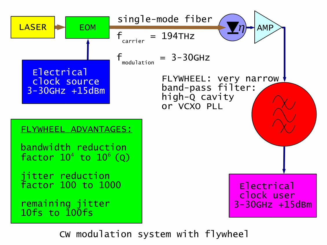
CW modulation system
LASER AMPsingle-mode fiber
fcarrier
= 194THz
fmodulation
= 3-30GHz
DRAWBACKS:
high photodetectorelectrical noise:jitter 1-10ps
low timingresolution?
ADVANTAGES:
simple temperaturecompensation
standard electricalinterfaces
standard hi-reltelecom components
Electrical clock source3-30GHz +15dBm
Electrical clock user3-30GHz +15dBm
EOM

@ C=1pF, T=300K
Pe≈30mW≈15dBm
C
U
electricaloutputG
electrical amplifier
R
Pn=B⋅k b⋅T B= 12⋅R⋅C
U neff= k b⋅T2⋅C=25.7V eff
U neff=Pn⋅R
photodiode
Photodiode electrical noise
Po≈1mW10mW
Pe≈1W≈−30dBm
LASER AMPsingle-mode fiber
fcarrier
= 194THz
fmodulation
= 3-30GHz
Electrical clock source3-30GHz +15dBm
Electrical clock user3-30GHz +15dBm
CW modulation system with flywheel
FLYWHEEL ADVANTAGES:
bandwidth reductionfactor 104 to 106 (Q)
jitter reduction factor 100 to 1000
remaining jitter10fs to 100fs
FLYWHEEL: very narrowband-pass filter:high-Q cavityor VCXO PLL
EOM

Delay-variation compensation techniques
LASER
AMP
compensationfiber
Electrical clock source3-30GHz +15dBm
Electrical clock user3-30GHz +15dBm
COMPENSATION TECHNIQUES:
DFB LASER electrictuning +/-0.5nm
DFB LASER temperature tuning +/-5nm
compensation fibertemperature tuning
FLYWHEEL
EOM
Peltier
transmissionfiber with
chromatic dispersionD ≈ 17ps/nm.km
λ tuning
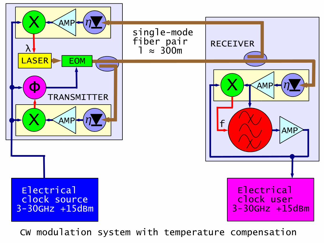
LASER
AMP
single-modefiber pair l ≈ 300m
EOM
fX
AMP X
Φ
Electrical clock source3-30GHz +15dBm
CW modulation system with temperature compensation
AMP X
Electrical clock user3-30GHz +15dBm
TRANSMITTER
RECEIVER
AMP
λ

LASER
AMP
single-mode fiber l ≈ 3km
EOM
fX
AMP X
Φ
Faradaymirror
CW modulation system with PMD compensation
AMP X
Electrical clock user3-30GHz +15dBm
TRANSMITTER
RECEIVER
AMP
λ
Electrical clock source3-30GHz +15dBm

uncorrectederror ±ΔΦTap RX
AMP
+
Electricalclock user #N3-30GHz +15dBm
AMP
Electrical clock source3-30GHz +15dBm
Multi-point chain clock distribution
Master TX
End-point RX
Electricalclock user #M3-30GHz +15dBm
distance#1 distance#2
+ΔΦ
+ΔΦ
-ΔΦ
-ΔΦ
Vector sum +ΔΦ
-ΔΦ=+ΔΦ-ΔΦ-ΔΦ
Tap
d#1 ≠ d#2

USER REQUIREMENTS:
optical input & output?
pulsed input & output?
integration with otherequipment?
diagnostics?
Future-developement action list
FLYWHEEL TECHNOLOGY:
ceramic materials fordielectric resonators
VCXO characterization
low-noise frequency multipliers anddividers
LASER TECHNOLOGY:
high-speed electronicwavelength tuning
low-coherence sources
direct laser modulation
safety & reliability
OPTICAL FIBER:
long-term, temperature& PMD characterization
connector performance
ferrite components:isolators, circulators& Faraday mirrors


![[XLS] · Web viewJARIT (1034) SAKATA (15) JAMBOREE FRX 926 STAR 7020 STAR 7022 STAR 7027 STAR 7053 NICKERS-ZWAAN (665) ZA 981918 ZA 20083836 ZA 981919 ZA 981920 ZA 20083819 ZA 20083820](https://static.fdocuments.in/doc/165x107/5b27899e7f8b9a0b498b7990/xls-web-viewjarit-1034-sakata-15-jamboree-frx-926-star-7020-star-7022.jpg)