Optical Aberrations Resident Lecture. The Perfect Image There is no such thing as a perfect image...
63
Optical Aberrations Resident Lecture
Transcript of Optical Aberrations Resident Lecture. The Perfect Image There is no such thing as a perfect image...

Optical Aberrations
Resident Lecture

The Perfect Image
There is no such thing as a perfect image
All light rays passing through optical systems are subject to distortions
Outline
Chromatic Aberration Spherical Aberration Oblique Astigmatism Coma Curvature of Field Distortion
Point Spread Function
Modulation Transfer Wavefront Analysis Custom Lasik and
Zernicke Polynomials

Chromatic Aberration
A lens will not focus different colors in exactly the same place.
the focal length depends on refraction and the index of refraction
Short wavelength has higher n and is refracted more than long wavelength
The amount of chromatic aberration depends on the dispersion of the glass.
Lens
Eye
http://micro.magnet.fsu.edu/primer/java/aberrations/spherical/index.html

Chromatic Aberration
Dispersive power (abbe value) is based on change in index for different wavelengths
If the index is the same for all wavelengths, there is NO DISPERSION
The n increases as wavelength decreases

Chromatic Aberration
Some patients can detect this Dispersion usually increases in high index May be noticeable with IOL’s

Chromatic AberrationDuochrome Test
Duochrome test helps you determine position of focal point with respect to the fovea
Useful to avoid overminusing pt.

Duochrome Test
Too much minus greenis clearer
Too much plus red is clearer

Chromatic Aberration-Duochrome Test
Red clarity= green claritythen image is positionedcorrectly.
534560564
Correction of Chromatic Aberration
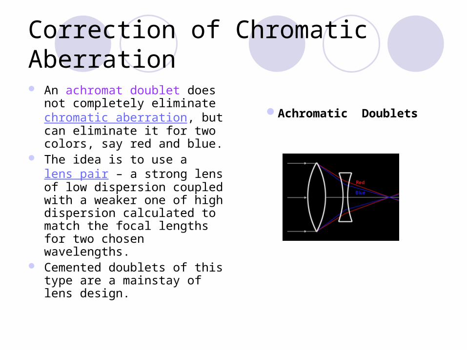
An achromat doublet does not completely eliminate chromatic aberration, but can eliminate it for two colors, say red and blue.
The idea is to use a lens pair – a strong lens of low dispersion coupled with a weaker one of high dispersion calculated to match the focal lengths for two chosen wavelengths.
Cemented doublets of this type are a mainstay of lens design.
Achromatic Doublets
Correction of Chromatic Aberration
APOCHROMATIC LENS The addition of a third lens corrects for three colors (red, blue and green), greatly reducing the fuzziness caused by the colors uncorrected in the achromatic doublet.

Correction of Chromatic Aberration
In the human eye, chromatic aberration is reduced by the lens, which changes index from the nucleus outward.

Spherical Aberration
For lenses made with spherical surfaces, rays which are parallel to the optic axis but at different distances from the optic axis fail to converge to the same point.
http://www.olympusmicro.com/primer/java/aberrations/spherical

Spherical Aberration- correction
Spherical aberration in the human eye is reduced by the aspheric shape of the lens and the cornea

Spherical Aberration- Correction
Meniscus LensesThe amount of spherical aberration in a lens made from spherical surfaces depends upon its shape. Best form, depends on base curve

Oblique Astigmatism
This aberration primarily influences the image quality of spherical lenses. When the wearer looks at an angle through the lens, there is a deviation which he perceives as blur. The higher the dioptric power of the lens, the more pronounced this error becomes.

Oblique Astigmatism
A dot is no longer imaged as a dot, but as two image lines.

Oblique astigmatism- correction
Mitigated by deviating from the spherical shape
Aspheric Surfaces to the Rescue
Coma
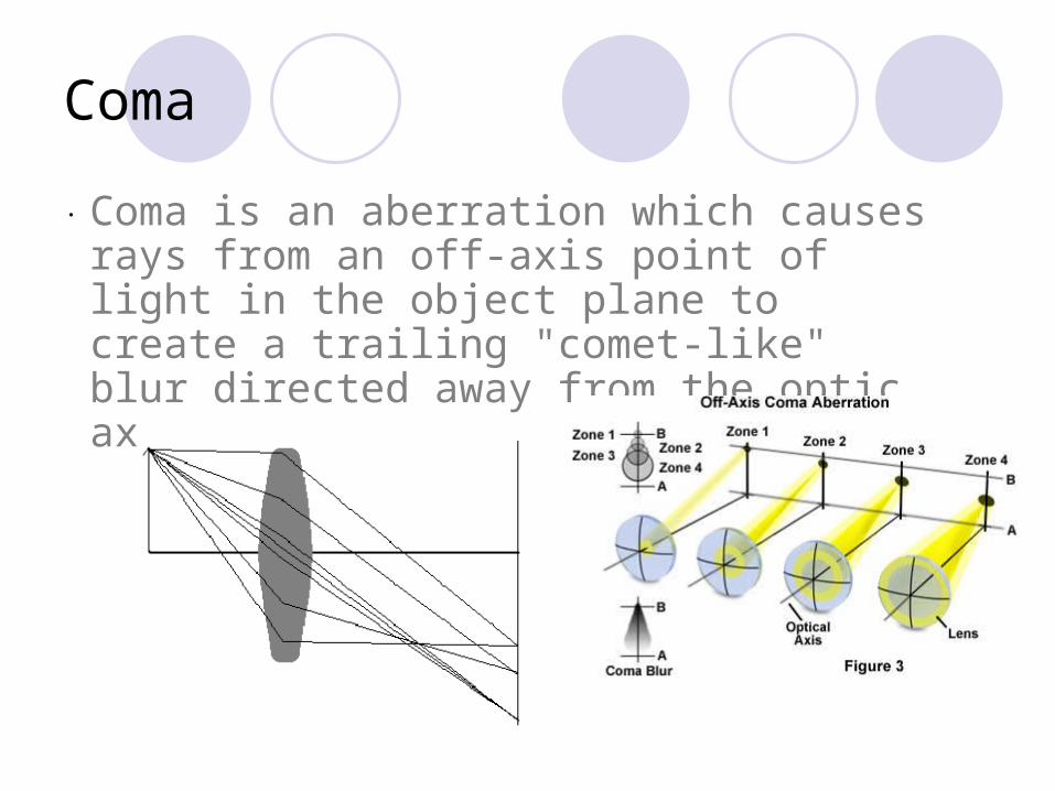
. Coma is an aberration which causes rays from an off-axis point of light in the object plane to create a trailing "comet-like" blur directed away from the optic axis.

Coma
A lens with
considerable coma may produce a sharp image in the center of the field, but become increasingly blurred toward the edges.

Coma
The resulting image is called a comatic circle. The coma flare, which owes its name to its cometlike tail, is often considered the worst of all aberrations, primarily because of its asymmetric configuration.

Coma- correction
For a single lens, coma can be partially corrected by bending the lens. More complete correction can be achieved by using a combination of lenses symmetric about a central stop.
Coma is not well compensated for in the human eye.

Curvature of Field
Causes an planar object to project a curved (nonplanar) image. It can be thought of as arising from a "power error" for rays at a large angle. Those rays treat the lens as having an effectively smaller diameter and an effectively higher power, forming the image of the off axis points closer to the lens.

Curvature of Field
A lens aberration that causes a flat object surface to be imaged onto a curved surface rather than a plane.
http://www.microscopyu.com/tutorials/java/aberrations/curvatureoffield/
=n*f2

Curvature of Field- Correction
The surface of the image formed by the eye is also curved, fortunately, the retina is also curved!
For lens systems, using best form lenses with non-spherical shapes can help.

Image Distortion
Not about sharpness, but faithful reproduction of the shape of the object.
It occurs when magnification varies with the distance of the object from the optic axis.
Problem only for high powers Tends to falsify the positions of objects and
cause vertical lines to wave Aphakes! Minimized by very steep back base curves

Image Distortion
Plus lens Minus lens

Outline
Chromatic Aberration Spherical Aberration Oblique Astigmatism Coma Curvature of Field Distortion
Point Spread Function
Modulation Transfer Wavefront Analysis Custom Lasik and
Zernicke Polynomials

Beyond sphere and cylinder…
Higher order aberrations have been traditionally ignored clinically
Now are routinely considered Post lasik increase in higher order aberrations Can be easily measured Wavefront guided correction available Patient expectations

History of wavefront sensing
DOD in the 1980’s to support “star wars” Measure the constantly fluctuating refractive power of the
atmosphere to improve accuracy of satellite photos and accuracy of weapons
Led to adaptive optics – real time measurements of refractions using “deformable mirrors” that rapidly
Astronomers were interested to improve telescope images
www.opt.pacificu.edu

Shack-Hartmann wavefront sensor
Hartmann first looked at this a century agoShack elaborated on this in the 1980’s
working for the air forceLiang was the first to use the wavefront
sensor to measure the human eye in 1994.
By the late 1990’s commercial development was occuring.

Airy Disc
When wave encounters and obstruction, the direction of the wave changes.
This is called DIFFRACTION
An Airy disc shows how a point image is degraded by aberration


Point Spread Function
Consider an object consisting of a perfect point. The image of this object will be at least one point wide. Normally it’s image will consist instead of a spot of several points, brightest in the centre and progressively darker away from the centre. This image function is the point-spread function.

Point Spread Function
used to assess the spatial resolution of an imaging system.
The PSF need not be symmetrical, so there may be different spatial resolutions in different directions.
Note that the PSF is, in most cases, a function with significant variation over the field of view.

Modulation Transfer Function
Used to assess the overall spatial resolution of an imaging system. It is formally defined as the magnitude of the Fourier transformed point spread function
The concept of the MTF is to portray how much of the contrast at a specific resolution is maintained by the imaging process.

Modulation Transfer Function
How can the degradation of an optical system be evaluated?
SQUARE WAVE
Max luminance
Min luminance
Modulation= Lmax-Lmin/Lmax+Lmin

Modulation Transfer Function
Square wave grating of specific frequency and contrast is passed through an optical system. The MODULATION can then be measured
MTF= Mi/Mo Luminance of stimulus
Luminance of image

Modulation Transfer Function
In the optimal case, the MTF value is 1 meaning that object and image contrast are identical.
MTF usually starts with a value 1 at 0 spatial frequency which represents a homogeneous background. It then drops in a system-specific manner down to zero. By using the MTF, two systems can readily be compared: At each spatial frequency (or 1/resolution) that system with the higher MTF maintains better contrast.

Wavefront analysis (wavescan)
Light is has both particle and wave characteristics
Wavefront analysis describes the wave behavior of light in the eye
Actual image displacement of the point source from foveola as it passes through the optical system of the eye compared to the ideal image.

Custom Lasik-Wavescan
Wavescan uses the principles of MTFCustom can correct for
Myopia or hyperopia Astigmatism Spherical Aberration Coma
Custom does not correct for Chromatic aberration Diffraction

Hartmann-Shack AberrommetryHow does it work….
Analyze light that emerges or is reflected from the retina and passes through the optical system of the eye.
Produces a “fingerprint” of the aberrations for an individual eye.

Measuring Aberrations
Emmetropia/ no aberrations
Myopia/distorted wavefront
Aberrometers measure the shape of the wavefront

Wavefront analysis
The distance between the wavefront surface and a reference plane
Wavefront exitingThe eye. Distance From the referencePlane is measured At many points.

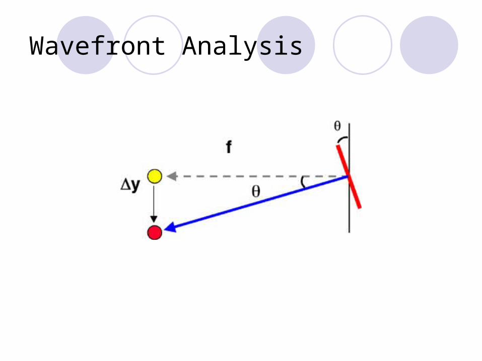
Hartmann Shack aberrometer
Each lenslet is a fraction of a mm. It divides the broad beam of lightInto many sub-beams for measurement. Each lenslet focuses onto the Video sensor. We analyze the position of each spot.

Wavefront Analysis
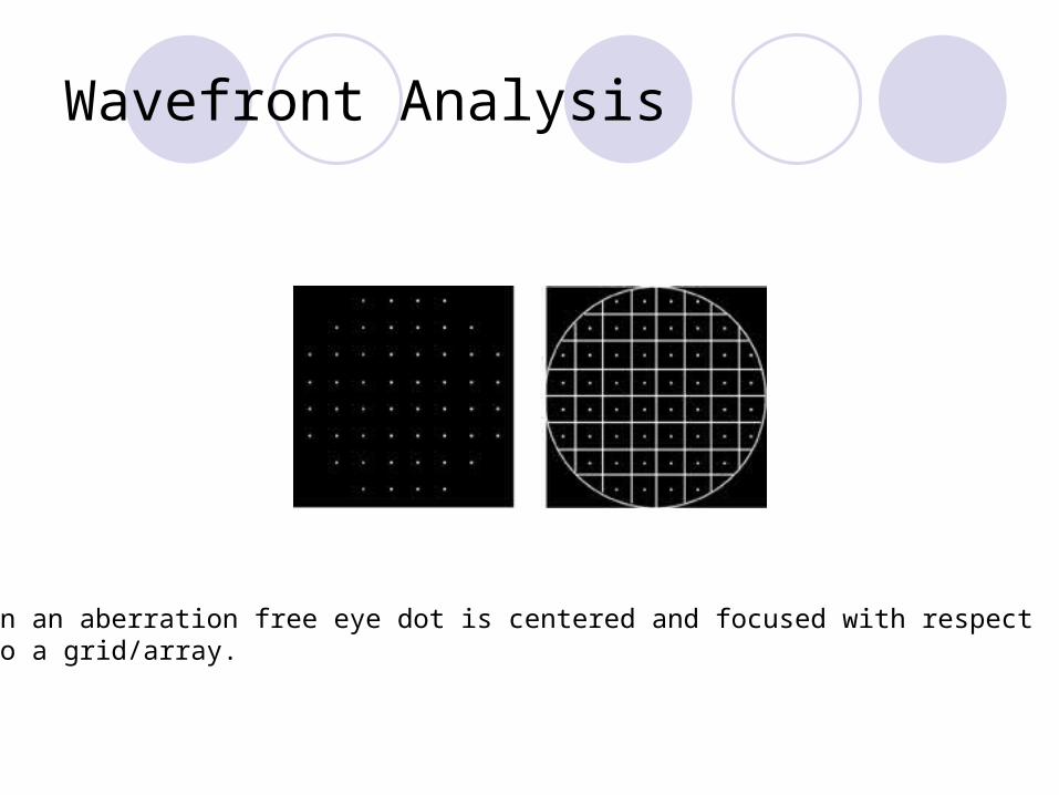
Wavefront Analysis
In an aberration free eye dot is centered and focused with respectTo a grid/array.
Wavefront Analysis

Wavefront Analysis
Sometimes it is easier to visualize the wavefront in a 3D surface plot
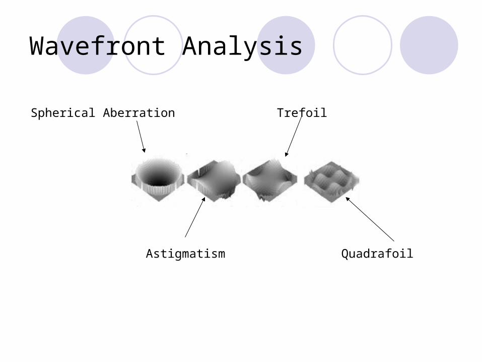
Wavefront Analysis
Spherical Aberration
Astigmatism
Trefoil
Quadrafoil

Wavefront Analysis – Root Mean Square
Measure of the deviation of an actual image from an ideal image of the source point object
RMS of ideal system is 0RMS of human eye increases from 0.1 to
0.25 at 60yo.Standard LASIK increases RMS especially
for large pupils.

What are Zernicke polynomials?
Monochromatic aberrations can be decomposed into Zernicke polynomials
Each ZP corresponds to a specific geometric pattern of aberration and are grouped into orders
These are mathematical expressions that describe how much of what type of geometric pattern is contributing to the total wavefront aberration.
Basically it is a system for categorizing higher order aberrations
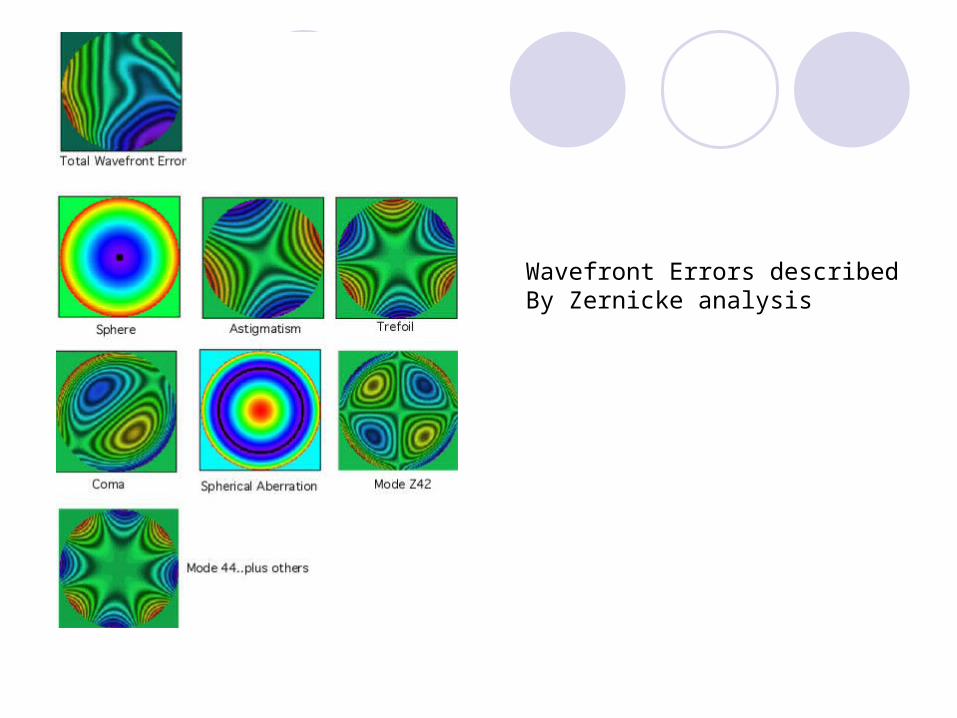
Wavefront Errors describedBy Zernicke analysis

Custom Lasik- Zernicke Polynomials
Each mode will have a number that is + or -. This coefficient tells you how much of that aberration is present
The units are not diopters, but microns Pupil size is included Will give you RMS Zernicke modes are grouped into orders
2nd order non wavefront 3rd order and above are “higher order”. They are labelled
using a double index scheme Znm, where n refers to the
order and m to the mode within the order. Some of the modes have names

Higher order aberrations and relative risk of symptoms after LASIK. Sharma M, Wachler BS, Chan CC.
RESULTS: Blurring of vision was the most common symptom (41.6%) followed by double image (19.4%), halo (16.7%), and
fluctuation in vision (13.9%) in symptomatic patients. A statistically significant difference was noted in UCVA (P
= .001), BSCVA (P = .001), contrast sensitivity (P < .001), and manifest cylinder (P = .001) in the two groups. The percentage difference between the symptomatic and control group mean root-mean-square (RMS) values ranged from 157% to 206% or 1.57 to 2.06 times greater. CONCLUSIONS: Patients with visual symptoms after LASIK have significantly lower visual acuity and contrast sensitivity and higher mean RMS values for higher order aberrations than patients without symptoms.
Root-mean-square values of greater than two times the normal after-LASIK J refractive surgery March 2007
Ocular higher-order aberrations and contrast sensitivity after conventional laser in situ keratomileusis Yamane N, Miyata K, Samejima T, IOVS 2004

Summary
Understand that ametropia is not the only thing that causes blurry vision
Understand that aberrations also plague lens systems in glasses, microscopes, etc.
Introduction to how refractive surgery (and IOL’s, spectacls and CLS) is attempting to compensate for aberrations inherent in the optics of the eye.

Presbyopic IOLs

Multifocal IOLs
http://www.eyeclinic.com.br/acrysoft/foto_04.jpg
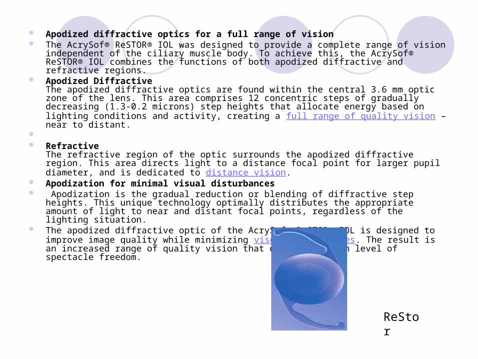
Apodized diffractive optics for a full range of vision The AcrySof® ReSTOR® IOL was designed to provide a complete range of vision independent of
the ciliary muscle body. To achieve this, the AcrySof® ReSTOR® IOL combines the functions of both apodized diffractive and refractive regions.
Apodized DiffractiveThe apodized diffractive optics are found within the central 3.6 mm optic zone of the lens. This area comprises 12 concentric steps of gradually decreasing (1.3-0.2 microns) step heights that allocate energy based on lighting conditions and activity, creating a full range of quality vision – near to distant.
Refractive
The refractive region of the optic surrounds the apodized diffractive region. This area directs light to a distance focal point for larger pupil diameter, and is dedicated to distance vision.
Apodization for minimal visual disturbances Apodization is the gradual reduction or blending of diffractive step heights. This unique
technology optimally distributes the appropriate amount of light to near and distant focal points, regardless of the lighting situation.
The apodized diffractive optic of the AcrySof® ReSTOR® IOL is designed to improve image quality while minimizing visual disturbances. The result is an increased range of quality vision that delivers a high level of spectacle freedom.
ReStor

ReZoom
Balanced View Optics™ Technology

ReZoom
Five focusing zones for a full range of vision The ReZoom™ Multifocal Lens has uniquely proportioned visual zones that provide it with its major advantage. Each ReZoom™ Multifocal Lens is divided into five different zones with each zone designed for different light and focal distances.

Distance centerNear adjacent Low light near and dist in the peripehryIntermediate one zone

Wavefront IOL
Tecnis IOL (AMO)Only wavefront-designed IOL with claims approved by the FDA for reduced spherical aberration, i
The Tecnis Z9001 IOL with a modified prolate anterior surface produces negative spherical aberration and consequently reduces the higher-order aberrations in pseudophakic eyes. This leads to enhanced contrast sensitivity and improved functional vision compared to conventional spherical IOLs.