OPM 3000 - Automation · PDF file2 OPM 3000 Opacity/Dust Density Monitor Emerson’s...
12
Product Data Sheet March 2016 OPM 3000 CMB-PDS-OPM-3000 OPM 3000 Opacity/Dust Density Monitor The OPM 3000 Opacity/Dust Density Monitor is a high-performance opacity monitoring system with double-pass transmissometer. Features Sensors Standard n USEPA ASTM D 6216 and 40 CFR 60 PS-1 grade optics n Alignment viewing port enables the operator to visually check system alignment at anytime during operation n Double pass measurement – Dual beam measurement assures high sensitivity, freedom from errors due to vibration or minor misalignment n Insensitive to ambient light –The solid-state light modulation system eliminates possible interference due to ambient light n Automatic lamp aging compensation – All measurements are made on a ratio basis and are independent of the absolute intensity of the light source Remote Control Unit n Three user selectable displays n Optional SD Card for program backup and changes n Communications via MODBUS RS485 or 4–20mA output n CE and (C)UL Listed n Password protected settings
Transcript of OPM 3000 - Automation · PDF file2 OPM 3000 Opacity/Dust Density Monitor Emerson’s...

Product Data SheetMarch 2016
OPM 3000 CMB-PDS-OPM-3000
OPM 3000Opacity/Dust Density Monitor
The OPM 3000 Opacity/Dust Density Monitor is a high-performance opacity monitoring system with double-pass transmissometer.
Features
Sensors Standard
n USEPA ASTM D 6216 and 40 CFR 60 PS-1 grade optics
n Alignment viewing port enables the operator to visually check system alignment at anytime during operation
n Double pass measurement – Dual beam measurement assures high sensitivity, freedom from errors due to vibration or minor misalignment
n Insensitive to ambient light –The solid-state light modulation system eliminates possible interference due to ambient light
n Automatic lamp aging compensation – All measurements are made on a ratio basis and are independent of the absolute intensity of the light source
Remote Control Unit
n Three user selectable displays
n Optional SD Card for program backup and changes
n Communications via MODBUS RS485 or 4–20mA output
n CE and (C)UL Listed
n Password protected settings
2
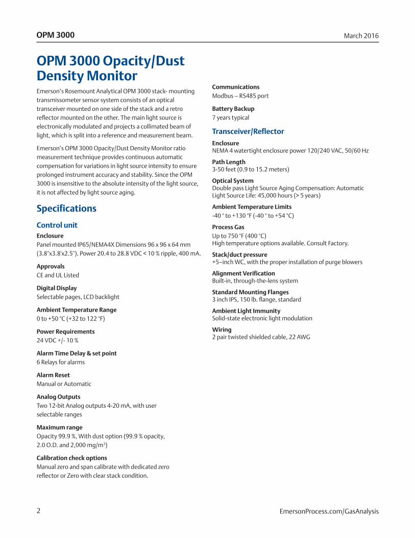
OPM 3000 Opacity/Dust Density MonitorEmerson’s Rosemount Analytical OPM 3000 stack- mounting transmissometer sensor system consists of an optical transceiver mounted on one side of the stack and a retro reflector mounted on the other. The main light source is electronically modulated and projects a collimated beam of light, which is split into a reference and measurement beam.
Emerson’s OPM 3000 Opacity/Dust Density Monitor ratio measurement technique provides continuous automatic compensation for variations in light source intensity to ensure prolonged instrument accuracy and stability. Since the OPM 3000 is insensitive to the absolute intensity of the light source, it is not affected by light source aging.
Specifications
Control unitEnclosure Panel mounted IP65/NEMA4X Dimensions 96 x 96 x 64 mm (3.8''x3.8'x2.5''). Power 20.4 to 28.8 VDC < 10 % ripple, 400 mA.
Approvals CE and UL Listed
Digital Display Selectable pages, LCD backlight
Ambient Temperature Range 0 to +50 °C (+32 to 122 °F)
Power Requirements 24 VDC +/- 10 %
Alarm Time Delay & set point 6 Relays for alarms
Alarm Reset Manual or Automatic
Analog Outputs Two 12-bit Analog outputs 4-20 mA, with user selectable ranges
Maximum range Opacity 99.9 %, With dust option (99.9 % opacity, 2.0 O.D. and 2,000 mg/m3)
Calibration check options Manual zero and span calibrate with dedicated zero reflector or Zero with clear stack condition.
Communications Modbus – RS485 port
Battery Backup 7 years typical
Transceiver/Reflector
Enclosure NEMA 4 watertight enclosure power 120/240 VAC, 50/60 Hz
Path Length 3-50 feet (0.9 to 15.2 meters)
Optical System Double pass Light Source Aging Compensation: Automatic Light Source Life: 45,000 hours (> 5 years)
Ambient Temperature Limits -40 ° to +130 °F (-40 ° to +54 °C)
Process Gas Up to 750 °F (400 °C) High temperature options available. Consult Factory.
Stack/duct pressure +5–inch WC, with the proper installation of purge blowers
Alignment Verification Built-in, through-the-lens system
Standard Mounting Flanges 3 inch IPS, 150 lb. flange, standard
Ambient Light Immunity Solid-state electronic light modulation
Wiring 2 pair twisted shielded cable, 22 AWG
OPM 3000 March 2016
EmersonProcess.com/GasAnalysis
3
Specifications (cont)Design and PerformancePeak and Mean Spectral Response Photopic; 515 to 585 nm, less than 10 % of peak response outside the desired 400 to 700 nm region
Angle of View < 4.0 ° from optical axis
Angle of Projection < 4.0 ° from optical axis
Calibration Error < +2 % of full scale
Response time < 10 second
Zero Drift < 1 % (24 hours)
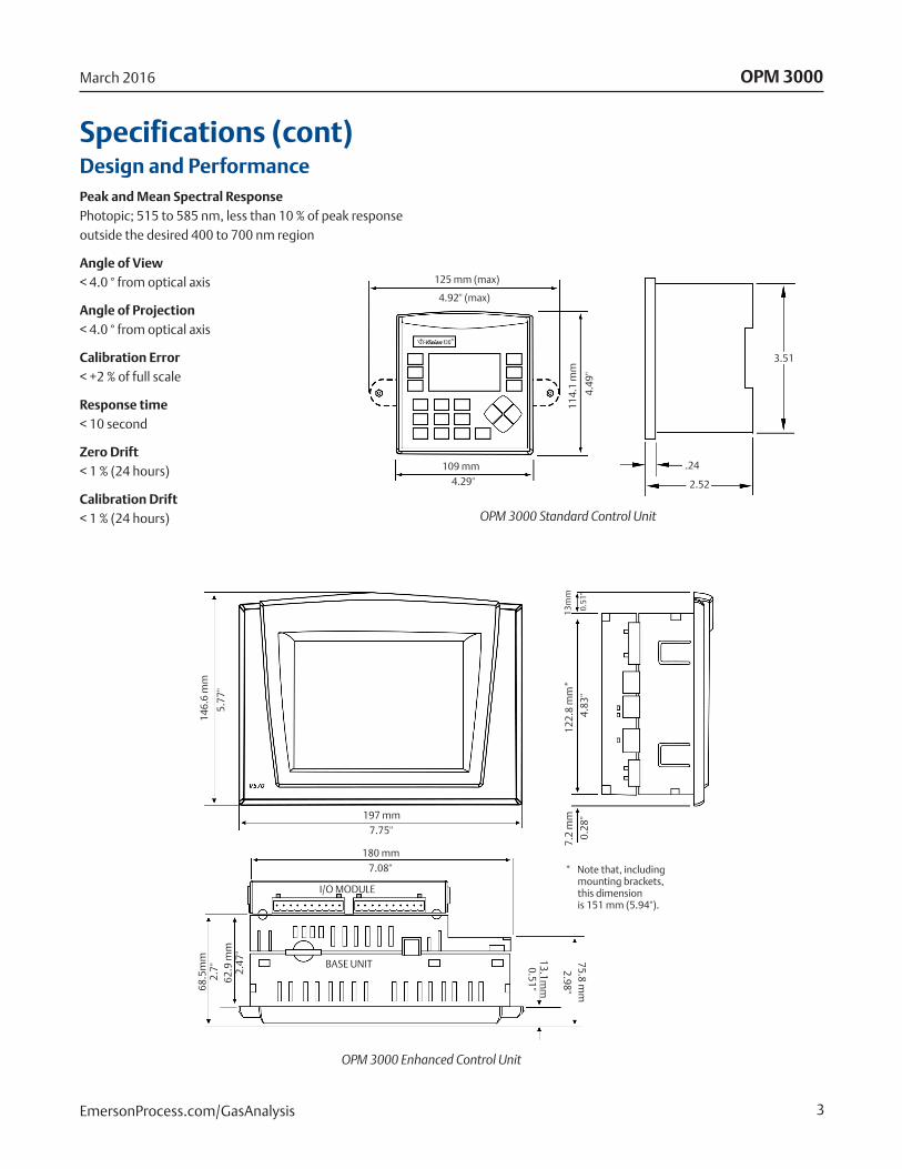
Calibration Drift < 1 % (24 hours) OPM 3000 Standard Control Unit
OPM 3000 Enhanced Control Unit
OPM 3000March 2016
EmersonProcess.com/GasAnalysis
125 mm (max)
4.92'' (max)
109 mm4.29''
114.
1 m
m
4.49
''
.24
2.52
3.51
197 mm7.75''
146.
6 m
m
5.77
''
7.2
mm
0.28
''
180 mm7.08''
122.
8 m
m*
4.83
''
13m
m
0.51
”
68.5
mm
2.7'
'62
.9 m
m2.
47''
75.8 mm
2.98''
13.1mm
0.51''
BASE UNIT
I/O MODULE
* Note that, including mounting brackets, this dimension is 151 mm (5.94'').

4
Electronic Display OptionsStandard Controller
n Dual beam measurement
n Clear Stack Zero
n User friendly microprocessor controller
n Easy to read numercial display
Additional features with Enhanced Touch screen
n Intuitively designed 5.7'' color touch screen user interface with expanded diagnostics
n 3 numerical and 2 trend display screens
n Optional SD card for program and data backup
n Color coded fault display/acknowledgement screen
Enhanced Touch Screen
OPM 3000
OPM 3000 March 2016
EmersonProcess.com/GasAnalysis

5
Electronic Display Comparsion Chart
w/Touch Screen Option
Standard OPM 3000
ASTM D 6216 and PS-1 compliant optics
Communications via 4-20 mA and RS MODBUS
Clear stack zero calibration
Microprocessor controller
3 numercial display screens
Intuitively designed icon driven navigation
Standard 3 analog outputs
Icon driven 5.7'' color touch screen user interface
Standard program includes % opacity, mg/m3 and O.D.
Optional 2GB SD card for program and data backup
Real-time diagnostics for testing outputs and relays
Two selectable trend screen displays
Easy to read color coded fault screen
User display customization available
OPM 3000March 2016
EmersonProcess.com/GasAnalysis

6
Dimensional DrawingsAir purge/Weather cover mechanical installation
*Note 1: The top view represents the transceiver and retro reflector assemblies with their swing clearances. Optional weather covers are not shown.
**Note 2: The side view represents the installation and swing clearance dimensions for the optional weather covers.
OPM 3000 March 2016
EmersonProcess.com/GasAnalysis
12.250 in.(311 mm)
R
Vertical Axis
6.125 in.(156 mm)
6 to 8 in.(152 to 203 mm) 6 to 8 in.
(152 to 203 mm)
6.125 (156 mm)
7.5 in.(191 mm)
R
Leave 3 in.(76 mm)
clearance fromflange face
for swinging
Top View *
Side View **
Cover in Upright Position
Stack or BreechingWall OD
Gas FlowMinimum Swing
Clearance34 in. (863.6 mm)
From Flange Center
Transceiver
Optional WeatherCover
60 in.(1524 mm)
Retro
30.5 (775 mm)(3) Covers
21.00 in. (533 mm)(2) Covers
Optional WeatherCover
Platform Platform

7
Flange to stack installation detail
OPM 3000March 2016
EmersonProcess.com/GasAnalysis
Field WeldPipe Flange to
Mounting Nipple
PipeFlange
VerticalAxis
7,5 in.(191 mm)
Dia.
6 in. (191 mm)Bolt Circle
StudAnchors
Outside WallSurface
Masonry StackWall Installation
Metal Wall Stackor Duct Installation
6 to 8 in.(152 - 203 mm)
Clearance
6 to 8 in.(152 - 203 mm)
Clearance
3 in. SCH 40Mounting Nipple
Field Weld MountingNipple to Pipe Flangeand Metal Stack/Duct Wall
Outside WallSurface

8
Model Product Description
OPM 3000 Opacity/Dust Density Monitor Non-compliant
Intelligent Electronics
01 Basic Unit – Digital Display, (2) 4–20 mA Outputs, (6) Alarm Relays, RS 232/485, Modbus
02 Enhanced Control Unit with 5.7'' LCD Color Touch Screen and SD Memory Storage
Transceiver and Path Length
11 3–15' Path Length
12 >15–21' Path Length
13 >21–40' Path Length
14 >40–50' Path Length
Weather Cover and Blower
00 None
01 Weather Covers
02 Weather Covers & Single Blower with Tee
03 Weather Covers & Dual Blowers
Zero Jig Type
00 None
01 Zero Jig, 75 % Neutral Density Filter and carrying case
Calculation
01 Opacity Calculation (%) for Standard Controller
02 Dust Density Calculation (mg/m3) for Standard Controller
03 Opacity and Dust Density Calculation (for Enhanced Controller Only)
Ordering InformationOPM 3000 Opacity/Dust Density Monitor - High performance opacity monitoring system with double-pass transmissometer.
OPM 3000 March 2016
EmersonProcess.com/GasAnalysis
9
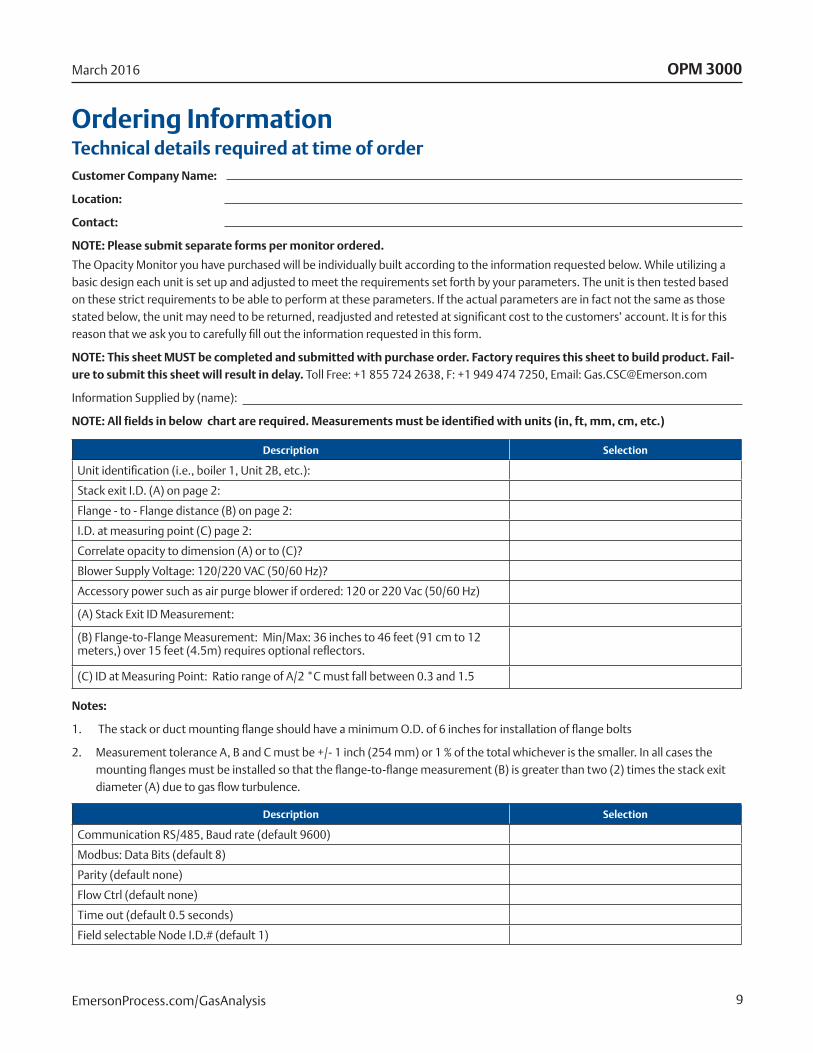
Ordering Information Technical details required at time of orderCustomer Company Name:
Location:
Contact:
NOTE: Please submit separate forms per monitor ordered.
The Opacity Monitor you have purchased will be individually built according to the information requested below. While utilizing a basic design each unit is set up and adjusted to meet the requirements set forth by your parameters. The unit is then tested based on these strict requirements to be able to perform at these parameters. If the actual parameters are in fact not the same as those stated below, the unit may need to be returned, readjusted and retested at significant cost to the customers’ account. It is for this reason that we ask you to carefully fill out the information requested in this form.
NOTE: This sheet MUST be completed and submitted with purchase order. Factory requires this sheet to build product. Fail-ure to submit this sheet will result in delay. Toll Free: +1 855 724 2638, F: +1 949 474 7250, Email: [email protected]
Information Supplied by (name):
NOTE: All fields in below chart are required. Measurements must be identified with units (in, ft, mm, cm, etc.)
OPM 3000March 2016
EmersonProcess.com/GasAnalysis
Description Selection
Unit identification (i.e., boiler 1, Unit 2B, etc.):
Stack exit I.D. (A) on page 2:
Flange - to - Flange distance (B) on page 2:
I.D. at measuring point (C) page 2:
Correlate opacity to dimension (A) or to (C)?
Blower Supply Voltage: 120/220 VAC (50/60 Hz)?
Accessory power such as air purge blower if ordered: 120 or 220 Vac (50/60 Hz)
(A) Stack Exit ID Measurement:
(B) Flange-to-Flange Measurement: Min/Max: 36 inches to 46 feet (91 cm to 12 meters,) over 15 feet (4.5m) requires optional reflectors.
(C) ID at Measuring Point: Ratio range of A/2 *C must fall between 0.3 and 1.5
Description Selection
Communication RS/485, Baud rate (default 9600)
Modbus: Data Bits (default 8)
Parity (default none)
Flow Ctrl (default none)
Time out (default 0.5 seconds)
Field selectable Node I.D.# (default 1)
Notes:
1. The stack or duct mounting flange should have a minimum O.D. of 6 inches for installation of flange bolts
2. Measurement tolerance A, B and C must be +/- 1 inch (254 mm) or 1 % of the total whichever is the smaller. In all cases the mounting flanges must be installed so that the flange-to-flange measurement (B) is greater than two (2) times the stack exit diameter (A) due to gas flow turbulence.
10
OPM 3000 March 2016
EmersonProcess.com/GasAnalysis
NOTE: If Modbus information is not filled in, our default values will be used. Only Modbus I.D. is field selectable. Other pa-rameters are fixed at time of final test according to the values given above or default. If changes to the communications are required after the system is shipped changes to the program must be made. All labor and shipping costs to make changes will be charged to the customer.

11
Ordering Information (con’t)Choose the drawing below that best fits the installation.
OPM 3000March 2016
EmersonProcess.com/GasAnalysis
A
Mounting Flange
B
C
A
B
C
Mounting Flange
Minimum of 2 stack diameters
OPM 3000CMB-PDS-OPM-3000
Product Data SheetMarch 2016
The Emerson logo is a trademark and service mark of Emerson Electric Co. Rosemount andthe Rosemount logotype are registered trademarks of Rosemount Inc. All other marks are theproperty of their respective owners.
©2016 Emerson Process Management. All rights reserved.
The contents of this publication are presented for information purposes only, and while effort has beenmade to ensure their accuracy, they are not to be construed as warranties or guarantees, express or implied, regarding the products or services described herein or their use or applicability. All sales are governed by our terms and conditions, which are available on request. We reserve the right to modify or improve the designs or specifications of our products at any time without notice.
EmersonProcess.com/GasAnalysis
Emerson Process Management2400 Barranca ParkwayIrvine, CA 92606USAToll Free +1 855 724 2638F +1 949 474 [email protected]
Analyticexpert.com
Twitter.com/Rosemount_News Facebook.com/Rosemount
YouTube.com/user/RosemountAnalytical