THE SIXTH SENSE DEVICE. WHAT IS THE SIXTH SENSE? WHAT IS THE SIXTH SENSE?
Third Edition
Sixth Printing
Part No. 43630
Operator’s Manualwith Maintenance Information

Genie Z-60/34 Part No. 43630
Operator's Manual Third Edition · Sixth Printing
Copyright © 1993 by Genie Industries
First Edition: First Printing, February, 1993
Second Edition: Third Printing, September 1996
Third Edition: Sixth Printing, November 2001
"Genie" and "Z" are registered trademarks ofGenie Industries in the U.S.A. and many othercountries.
These machines comply withANSI/SIA 92.5-1992.
Printed on recycled paper
Printed in U.S.A.
Important
Read, understand and obey these safety rules andoperating instructions before operating this machine.Only trained and authorized personnel shall bepermitted to operate this machine. This manual isconsidered a permanent part of your machine andshould remain with the machine at all times. If you haveany questions, call Genie Industries.
Contents
PageSafety Rules .............................................................. 1Controls ..................................................................... 7Pre-operation Inspection ........................................... 10Maintenance ............................................................. 12Function Tests .......................................................... 16Workplace Inspection ................................................ 23Operating Instructions ............................................... 24Decals ...................................................................... 28Transport Instructions ............................................... 30Specifications ........................................................... 31
Contact us:
Internet: http://www.genielift.comE-mail: [email protected]

Part No. 43630 Genie Z-60/34 1
Operator's ManualThird Edition · Sixth Printing
Safety Rules
Danger
Failure to obey the instructions andsafety rules in this manual willresult in death or serious injury.
Do Not Operate Unless:
You learn and practice the principles of safemachine operation contained in this operator'smanual.
1 Avoid hazardous situations.
Know and understand the safety rules beforegoing on to the next section.
2 Always perform a pre-operation inspection.
3 Always perform function tests prior to use.
4 Inspect the workplace.
5 Only use the machine as it was intended.
You read, understand and obey:
Manufacturer's instructions and safetyrules—safety and operator's manualsand machine decals
employer's safety rules and worksiteregulations
applicable governmental regulations
You are properly trained to safely operate themachine.
2 Genie Z-60/34 Part No. 43630
Operator's Manual Third Edition · Sixth Printing
SAFETY RULES
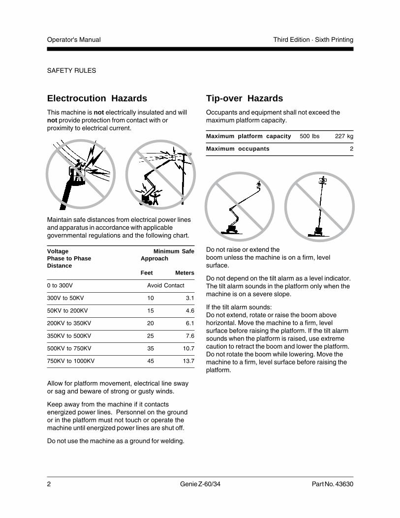
Electrocution HazardsThis machine is not electrically insulated and willnot provide protection from contact with orproximity to electrical current.
Maintain safe distances from electrical power linesand apparatus in accordance with applicablegovernmental regulations and the following chart.
Voltage Minimum SafePhase to Phase ApproachDistance
Feet Meters
0 to 300V Avoid Contact
300V to 50KV 10 3.1
50KV to 200KV 15 4.6
200KV to 350KV 20 6.1
350KV to 500KV 25 7.6
500KV to 750KV 35 10.7
750KV to 1000KV 45 13.7
Allow for platform movement, electrical line swayor sag and beware of strong or gusty winds.
Keep away from the machine if it contactsenergized power lines. Personnel on the groundor in the platform must not touch or operate themachine until energized power lines are shut off.
Do not use the machine as a ground for welding.
Tip-over HazardsOccupants and equipment shall not exceed themaximum platform capacity.
Maximum platform capacity 500 lbs 227 kg
Maximum occupants 2
Do not raise or extend theboom unless the machine is on a firm, levelsurface.
Do not depend on the tilt alarm as a level indicator.The tilt alarm sounds in the platform only when themachine is on a severe slope.
If the tilt alarm sounds:Do not extend, rotate or raise the boom abovehorizontal. Move the machine to a firm, levelsurface before raising the platform. If the tilt alarmsounds when the platform is raised, use extremecaution to retract the boom and lower the platform.Do not rotate the boom while lowering. Move themachine to a firm, level surface before raising theplatform.
Part No. 43630 Genie Z-60/34 3
Operator's ManualThird Edition · Sixth Printing
SAFETY RULES
Do not alter or disable machine components that inany way affect safety and stability.
Do not replace items critical to machine stabilitywith items of different weight or specification.
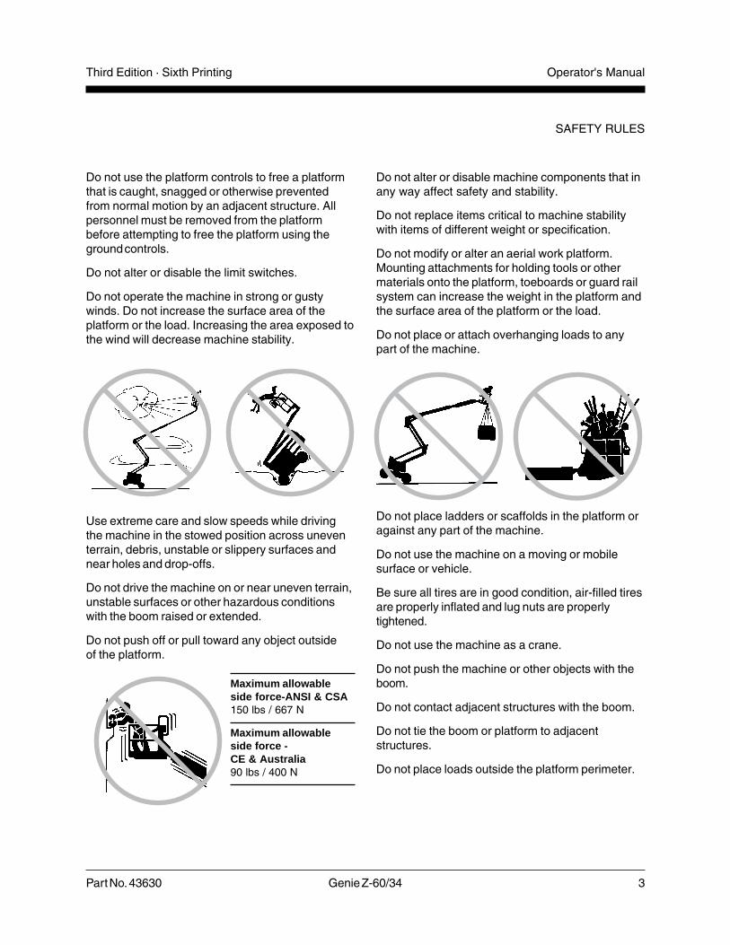
Do not modify or alter an aerial work platform.Mounting attachments for holding tools or othermaterials onto the platform, toeboards or guard railsystem can increase the weight in the platform andthe surface area of the platform or the load.
Do not place or attach overhanging loads to anypart of the machine.
Do not place ladders or scaffolds in the platform oragainst any part of the machine.
Do not use the machine on a moving or mobilesurface or vehicle.
Be sure all tires are in good condition, air-filled tiresare properly inflated and lug nuts are properlytightened.
Do not use the machine as a crane.
Do not push the machine or other objects with theboom.
Do not contact adjacent structures with the boom.
Do not tie the boom or platform to adjacentstructures.
Do not place loads outside the platform perimeter.
Do not use the platform controls to free a platformthat is caught, snagged or otherwise preventedfrom normal motion by an adjacent structure. Allpersonnel must be removed from the platformbefore attempting to free the platform using theground controls.
Do not alter or disable the limit switches.
Do not operate the machine in strong or gustywinds. Do not increase the surface area of theplatform or the load. Increasing the area exposed tothe wind will decrease machine stability.
Use extreme care and slow speeds while drivingthe machine in the stowed position across uneventerrain, debris, unstable or slippery surfaces andnear holes and drop-offs.
Do not drive the machine on or near uneven terrain,unstable surfaces or other hazardous conditionswith the boom raised or extended.
Do not push off or pull toward any object outsideof the platform.
Maximum allowableside force-ANSI & CSA150 lbs / 667 N
Maximum allowableside force -CE & Australia90 lbs / 400 N

4 Genie Z-60/34 Part No. 43630
Operator's Manual Third Edition · Sixth Printing
SAFETY RULES
Fall HazardsOccupants must wear asafety belt or harness inaccordance withgovernmental regulations.Attach the lanyard to theanchor provided in theplatform.
It is recommended that operators wear an approvedhard hat when operating the machine.
Do not sit, stand or climb on the platform guardrails. Maintain a firm footing on the platform floor atall times.
Do not climb down from the platform when raised.
Keep the platform floor clear of debris.
Lower the platform entry mid-rail or close the entrygate before operating.
Explosion and Fire HazardsDo not start the engine if you smell or detect liquidpetroleum gas (LPG), gasoline, diesel fuel or otherexplosive substances.
Do not refuel the machine with the engine running.
Refuel the machine and charge the battery only inan open, well-ventilated area away from sparks,flames and lighted tobacco.
Do not operate the machine in hazardous locationsor locations where potentially flammable orexplosive gases or particles may be present.
Collision HazardsBe aware of limited sightdistance and blind spotswhen driving or operating.
Be aware of the boom position when rotating theturntable.
Check work area for overhead obstructions or otherpossible hazards.
Be aware of crushing hazards when grasping theplatform guard rail.
Part No. 43630 Genie Z-60/34 5
Operator's ManualThird Edition · Sixth Printing
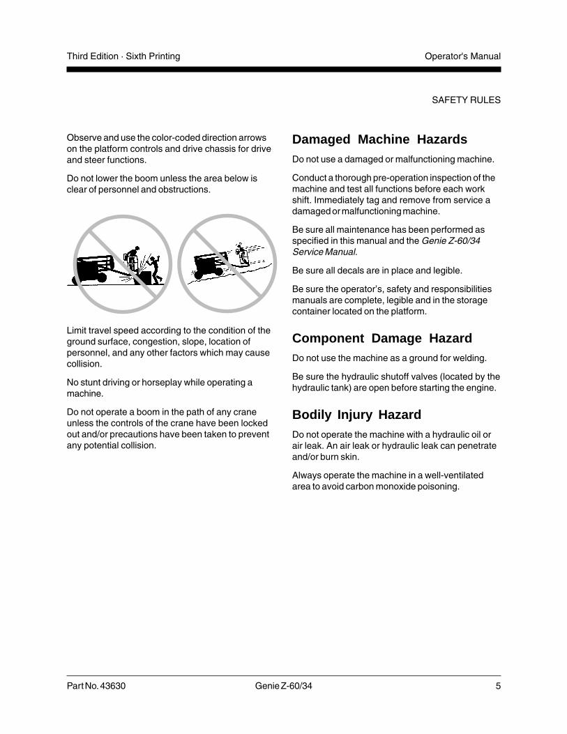
Observe and use the color-coded direction arrowson the platform controls and drive chassis for driveand steer functions.
Do not lower the boom unless the area below isclear of personnel and obstructions.
Limit travel speed according to the condition of theground surface, congestion, slope, location ofpersonnel, and any other factors which may causecollision.
No stunt driving or horseplay while operating amachine.
Do not operate a boom in the path of any craneunless the controls of the crane have been lockedout and/or precautions have been taken to preventany potential collision.
Damaged Machine HazardsDo not use a damaged or malfunctioning machine.
Conduct a thorough pre-operation inspection of themachine and test all functions before each workshift. Immediately tag and remove from service adamaged or malfunctioning machine.
Be sure all maintenance has been performed asspecified in this manual and the Genie Z-60/34Service Manual.
Be sure all decals are in place and legible.
Be sure the operator’s, safety and responsibilitiesmanuals are complete, legible and in the storagecontainer located on the platform.
Component Damage HazardDo not use the machine as a ground for welding.
Be sure the hydraulic shutoff valves (located by thehydraulic tank) are open before starting the engine.
Bodily Injury HazardDo not operate the machine with a hydraulic oil orair leak. An air leak or hydraulic leak can penetrateand/or burn skin.
Always operate the machine in a well-ventilatedarea to avoid carbon monoxide poisoning.
SAFETY RULES

6 Genie Z-60/34 Part No. 43630
Operator's Manual Third Edition · Sixth Printing
SAFETY RULES
Battery Safety
Burn HazardsBatteries contain acid. Always wear protectiveclothing and eyewear when working with batteries.
Avoid spilling or contacting battery acid. Neutralizebattery acid spills with baking soda and water.
Explosion HazardKeep sparks, flames and lighted tobacco awayfrom the battery. Batteries emit explosive gas.
Electrocution HazardAvoid contact with electrical terminals.
Component Damage HazardDo not use any battery or charger greater than 12Vto jump-start the engine or charge the battery.
Decal LegendGenie product decals use symbols, color codingand signal words to identify the following:
Safety alert symbol—used to alertpersonnel to potential personalinjury hazards. Obey all safetymessages that follow this symbolto avoid possible injury or death.
Red—used to indicate thepresence of an imminentlyhazardous situation which, if notavoided, will result in death orserious injury.
Orange—used to indicate thepresence of a potentiallyhazardous situation which, if notavoided, could result in death orserious injury.
Yellow with safety alert symbol—used to indicate the presence of apotentially hazardous situationwhich, if not avoided, may causeminor or moderate injury.
Yellow without safety alertsymbol—used to indicate thepresence of a potentiallyhazardous situation which, if notavoided, may result in propertydamage.
Green—used to indicate operationor maintenance information.

Part No. 43630 Genie Z-60/34 7
Operator's ManualThird Edition · Sixth Printing
Controls
Ground Control Panel
1 Platform rotate switch2 Turntable rotate switch3 Primary boom up/down switch4 Primary boom extend/retract switch5 Secondary boom up/down switch6 Key switch for platform/off/ground selection7 Auxiliary power switch8 Gasoline/LPG models: Water temperature
gaugeDeutz Diesel models: Oil temperature gauge
9 Oil pressure gauge10 Voltage gauge
11 Red Emergency Stop button12 Hour meter13 Gasoline/LPG models: Check engine light
Deutz Diesel models: Glow plug switch(option)
14 Function enable switch15 Engine start switch16 15A breaker for engine electrical circuits17 Gasoline/LPG select switch18 15A breaker for control electrical circuits19 Jib boom up/down switch20 Platform level switch
11
12
15171920 1618
7
6
8 9 10
1
2
3
5
4
14
13
8 Genie Z-60/34 Part No. 43630
Operator's Manual Third Edition · Sixth Printing
CONTROLS
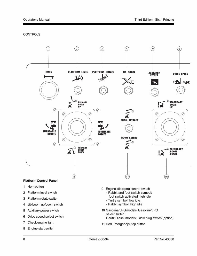
Platform Control Panel
1 Horn button
2 Platform level switch
3 Platform rotate switch
4 Jib boom up/down switch
5 Auxiliary power switch
6 Drive speed select switch
7 Check engine light
8 Engine start switch
9 Engine idle (rpm) control switch- Rabbit and foot switch symbol:
foot switch activated high idle- Turtle symbol: low idle- Rabbit symbol: high idle
10 Gasoline/LPG models: Gasoline/LPGselect switchDeutz Diesel models: Glow plug switch (option)
11 Red Emergency Stop button
1 2 3 4 5 6
161718

Part No. 43630 Genie Z-60/34 9
Operator's ManualThird Edition · Sixth Printing
CONTROLS
12 Proportional control handle for drive function andthumb rocker for steer function
13 Optional equipment
14 Drive enable indicator light
15 Drive enable switch
16 Proportional control handle for secondary boomup/down function
17 Primary boom extend/retract switch
18 Dual axis proportional control handle for primaryboom up/down and turntable rotate left/rightfunctions
8 9 10 11
1215 131314
7

10 Genie Z-60/34 Part No. 43630
Operator's Manual Third Edition · Sixth Printing
Pre-operation Inspection
Do Not Operate Unless:
You learn and practice the principles of safemachine operation contained in this operator'smanual.
1 Avoid hazardous situations.
2 Always perform a pre-operationinspection.
Know and understand the pre-operationinspection before going on to the nextsection.
3 Always perform function tests prior to use.
4 Inspect the workplace.
5 Only use the machine as it was intended.
FundamentalsIt is the responsibility of the operator to perform aPre-operation Inspection and routine maintenance.
The Pre-operation Inspection is a visual inspectionperformed by the operator prior to each work shift.The inspection is designed to discover if anythingis apparently wrong with a machine before theoperator performs the function tests.
The Pre-operation inspection also serves todetermine if routine maintenance procedures arerequired. Only routine maintenance items specifiedin this manual may be performed by the operator.
Refer to the list on the next page and check eachof the items and locations for modifications,damage or loose or missing parts.
A damaged or modified machine must never beused. If damage or any variation from factorydelivered condition is discovered, the machinemust be tagged and removed from service.
Repairs to the machine may only be made by aqualified service technician, according to themanufacturer's specifications. After repairs arecompleted, the operator must perform apre-operation inspection again before going on tothe function tests.
Scheduled maintenance inspections shall beperformed by qualified service technicians,according to the manufacturer's specifications andthe requirements listed in the responsibilitiesmanual.

Part No. 43630 Genie Z-60/34 11
Operator's ManualThird Edition · Sixth Printing
PRE-OPERATION INSPECTION
Pre-operation Inspection
� Be sure that the operator’s, safety andresponsibilities manuals are complete, legibleand in the storage container located in theplatform.
� Be sure that all decals are legible and in place.See Decals section.
� Check for engine oil leaks and proper oil level.Add oil if needed. See Maintenance section.
� Check for hydraulic oil leaks and proper oil level.Add oil if needed. See Maintenance section.
� Check for engine coolant leaks and proper levelof coolant. Add coolant if needed. SeeMaintenance section.
� Check for battery fluid leaks and proper fluidlevel. Add distilled water if needed. SeeMaintenance section.
� Check for proper tire pressure. Add air if needed.See Maintenance section.
Check the following components or areas fordamage, modifications and improperly installed ormissing parts:
� Electrical components, wiring andelectrical cables
� Hydraulic hoses, fittings, cylinders andmanifolds
� Fuel and hydraulic tanks
� Drive and turntable motors and drive hubs
� Boom wear pads
� Tires and wheels
� Engine and related components
� Limit switches and horn
� Alarms and beacons (if equipped)
� Nuts, bolts and other fasteners
� Platform entry mid-rail or gate
Check entire machine for:
� Crack in welds or structural components
� Dents or damage to machine
� Be sure that all structural and other criticalcomponents are present and all associatedfasteners and pins are in place and properlytightened.
� After you complete your inspection, be sure thatall compartment covers are in place andlatched.
12 Genie Z-60/34 Part No. 43630
Operator's Manual Third Edition · Sixth Printing
Maintenance
Observe and Obey:
Only routine maintenance items specified in thismanual shall be performed by the operator.
Scheduled maintenance inspections shall becompleted by qualified service technicians,according to the manufacturer's specificationsand the requirements specified in theresponsibilities manual.
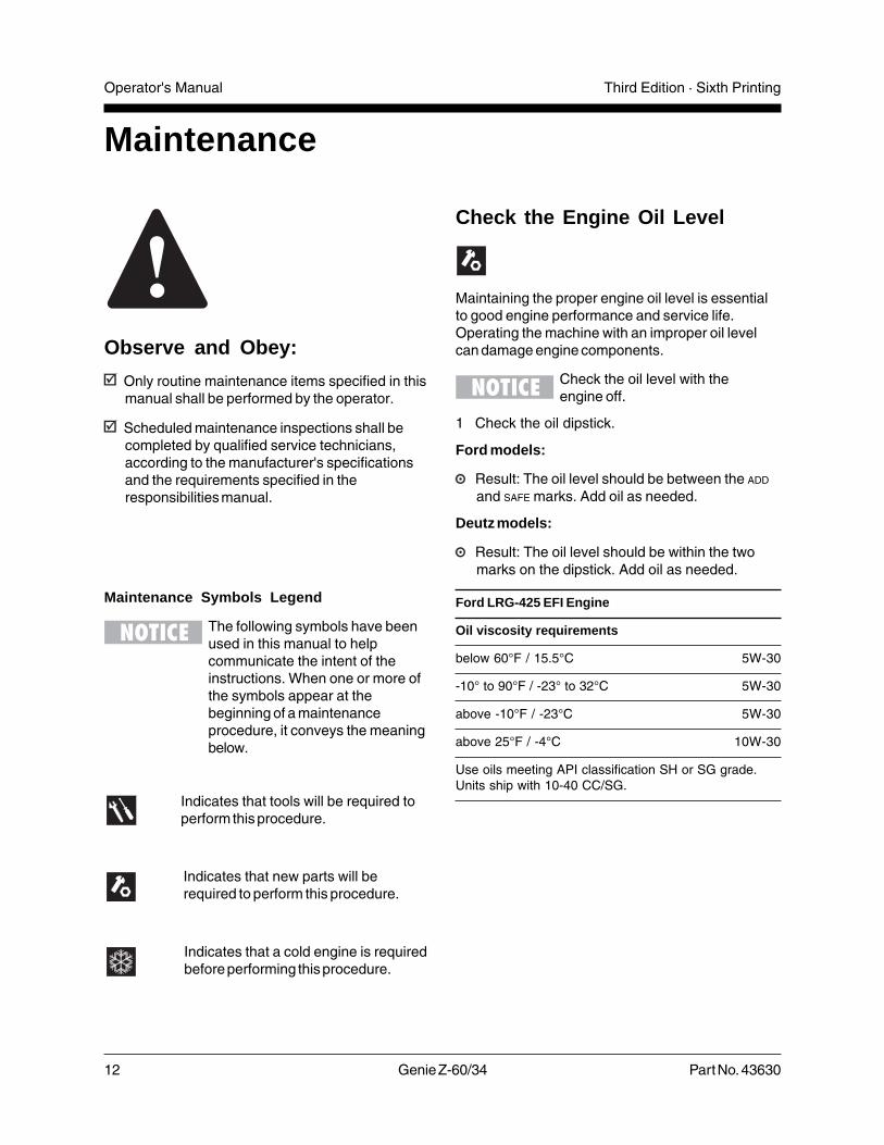
Maintenance Symbols Legend
The following symbols have beenused in this manual to helpcommunicate the intent of theinstructions. When one or more ofthe symbols appear at thebeginning of a maintenanceprocedure, it conveys the meaningbelow.
Indicates that tools will be required toperform this procedure.
Indicates that new parts will berequired to perform this procedure.
Indicates that a cold engine is requiredbefore performing this procedure.
Check the Engine Oil Level
Maintaining the proper engine oil level is essentialto good engine performance and service life.Operating the machine with an improper oil levelcan damage engine components.
Check the oil level with theengine off.
1 Check the oil dipstick.
Ford models:
Result: The oil level should be between the ADD
and SAFE marks. Add oil as needed.
Deutz models:
Result: The oil level should be within the twomarks on the dipstick. Add oil as needed.
Ford LRG-425 EFI Engine
Oil viscosity requirements
below 60°F / 15.5°C 5W-30
-10° to 90°F / -23° to 32°C 5W-30
above -10°F / -23°C 5W-30
above 25°F / -4°C 10W-30
Use oils meeting API classification SH or SG grade.Units ship with 10-40 CC/SG.

Part No. 43630 Genie Z-60/34 13
Operator's ManualThird Edition · Sixth Printing
MAINTENANCE
Check the Hydraulic Oil Level
Maintaining the hydraulic oil at the proper level isessential to machine operation. Improper hydraulicoil levels can damage hydraulic components. Dailychecks allow the inspector to identify changes in oillevel that might indicate the presence of hydraulicsystem problems.
1 Be sure that the boom is in the stowed position,then visually inspect the sight gauge located onthe side of the hydraulic oil tank. Add oil asneeded.
Result: The hydraulic oil level should be withinthe top 2 inches / 5 cm of the sight gauge.
Hydraulic oil specifications
Hydraulic oil type Dexron equivalent
Deutz F4L 1011F Engine
Oil viscosity requirements
below 60°F / 15.5°C (synthetic) 5W-30
-10°F to 90°F / -23°C to 32°C 10W-40
above -4°F / -34°C 15W-40
Engine oil should have properties of API classificationCC/SE or CC/SF grades.Units ship with 10-40 CC/SG.

14 Genie Z-60/34 Part No. 43630
Operator's Manual Third Edition · Sixth Printing
Check the Engine Coolant Level- Gasoline/LPG Models
Maintaining the engine coolant at the proper level isessential to engine service life. Improper coolantlevel will affect the engine's cooling capability anddamage engine components. Daily checks willallow the inspector to identify changes in coolantlevel that might indicate cooling system problems.
Burn hazard. Beware of hot engineparts and coolant. Contact with hotengine parts and/or coolant maycause severe burns.
1 Check the fluid level in the coolant recoverytank. Add fluid as needed.
Result: The fluid level should be at theFULL mark.
Bodily injury hazard. Fluids in theradiator are under pressure andextremely hot. Use caution whenremoving cap and adding fluids.
Check the Batteries
Proper battery condition is essential to good engineperformance and operational safety. Improper fluidlevels or damaged cables and connections canresult in engine component damage and hazardousconditions.
This procedure does not need tobe performed on machines withsealed or maintenance-freebatteries.
Electrocution hazard. Contact withhot or live circuits may result indeath or serious injury. Remove allrings, watches and other jewelry.
Bodily injury hazard. Batteriescontain acid. Avoid spilling orcontacting battery acid. Neutralizebattery acid spills with baking sodaand water.
1 Put on protective clothing and eye wear.
2 Be sure that the battery cable connections aretight and free of corrosion.
3 Be sure that the battery hold-down bar is inplace.
4 Remove the battery vent caps.
5 Check the battery acid level. If needed,replenish with distilled water to the bottom of thebattery fill tube. Do not overfill.
6 Install the vent caps.
Adding terminal protectors and acorrosion preventative sealant willhelp eliminate corrosion on thebattery terminals and cables.
MAINTENANCE

Part No. 43630 Genie Z-60/34 15
Operator's ManualThird Edition · Sixth Printing
Check the Tire Pressure
This procedure does not needto be performed on machinesequipped with the foam-filledtire option.
Bodily injury hazard. An over-inflated tire can explode and couldcause death or serious injury.
Tip-over hazard. Do not usetemporary flat tire repair products.
To safeguard maximum stability, achieveoptimum machine handling and minimize tirewear, it is essential to maintain proper pressurein all air-filled tires.
1 Check each tire with an air pressure gauge. Addair as needed.
Tire specifications Industrial RoughTerrain
Tire size 32 x 12-15 NHS 15-19.5 NHS300-15 NHS
Pressure 110 psi 60 psi7.6 bar 4.14 bar
MAINTENANCE
Scheduled MaintenanceMaintenance performed quarterly, annually andevery two years must be completed by a persontrained and qualified to perform maintenance on thismachine according to the procedures found in theservice manual for this machine.
Machines that have been out of service for morethan three months must receive the quarterlyinspection before they are put back into service.
16 Genie Z-60/34 Part No. 43630
Operator's Manual Third Edition · Sixth Printing
Function Tests
FundamentalsThe Function Tests are designed to discover anymalfunctions before the machine is put into service.The operator must follow the step-by-stepinstructions to test all machine functions.
A malfunctioning machine must never be used. Ifmalfunctions are discovered, the machine must betagged and removed from service. Repairs to themachine may only be made by a qualified servicetechnician, according to the manufacturer'sspecifications.
After repairs are completed, the operator mustperform a pre-operation inspection and functiontests again before putting the machine into service.
Symbol Legend
Indicates that a specific result is expected afterperforming a series of steps.
Do Not Operate Unless:
You learn and practice the principles of safemachine operation contained in this operator'smanual.
1 Avoid hazardous situations.
2 Always perform a pre-operationinspection.
3 Always perform function tests prior touse.
Know and understand the function testsbefore going on to the next section.
4 Inspect the workplace.
5 Only use the machine as it was intended.

Part No. 43630 Genie Z-60/34 17
Operator's ManualThird Edition · Sixth Printing
1 Select a test area that is firm, level and free ofobstruction.
At the Ground Controls2 Turn the key switch to ground control.
3 Pull out the red Emergency Stop button tothe ON position.
Result: The beacon (if equipped) should flash.
4 Start the engine. See Operating Instructionssection.
Test Emergency Stop
5 Push in the red Emergency Stop button to theOFF position.
Result: The engine should turn off and allfunctions should not operate.Deutz Diesel models: The engine will shut offafter 2 to 3 seconds.
6 Pull out the red Emergency Stop button tothe ON position and restart the engine.
Test the Machine Functions
7 Do not hold the function enable switch to eitherside. Attempt to activate each boom andplatform function toggle switch.
Result: All boom and platform functions shouldnot operate.
8 Hold the function enable switch to either sideand activate each boom and platform functiontoggle switch.
Result: All boom and platform functions shouldoperate through a full cycle. The descent alarm(if equipped) should sound while the boom islowering.
Machines equipped with Platform Level ControlDisable Function: The platform level toggle switchwill not operate when the primary boom is raisedor extended or the secondary boom is raised pastthe drive speed limit switches.
Test the Tilt Sensor
9 Pull out the platform red Emergency Stop buttonto the ON position.
10 Turn the key switch to platformcontrol.
11 Open the control panel sideturntable cover and locate the tiltsensor next to the control box.
12 Press down one side of the tiltsensor.Result: The alarm, located in theplatform, should sound.
Test Auxiliary Controls
13 Turn the key switch to ground control and shutthe engine off.
14 Pull out the red Emergency Stop button to theON position.
15 Simultaneously hold the auxiliary power switchon and activate each boom function toggleswitch.
Note: To conserve battery power, test eachfunction through a partial cycle.
Result: All boom functions should operate.
Machines equipped with oscillating axles: From thestowed position, auxiliary power can not raise theprimary boom above the drive limit switch. Auxiliarypower can raise the primary boom if it is alreadyraised above the drive limit switch.
FUNCTION TESTS

18 Genie Z-60/34 Part No. 43630
Operator's Manual Third Edition · Sixth Printing
FUNCTION TESTS
Test Oscillate Lock-out (if equipped)
16 Start the engine and raise the primary boomapproximately 2 feet / 61 cm.
Result: The oscillationlock-out wedges shouldfully extend.
17 Lower the primary boomto the stowed position.
Result: The oscillationlock-out wedges shouldfully retract.
18 Extend the primary boom approximately2 ft / 61 cm.
Result: The oscillation lock-out wedges shouldfully extend.
19 Fully retract the primary boom.
Result: The oscillation lock-out wedges shouldfully retract.
20 Raise the secondary boom approximately2 feet / 61 cm.
Result: The oscillation lock-out wedges shouldfully extend.
21 Lower the secondary boom to the stowedposition.
Result: The oscillation lock-out wedges shouldfully retract.
22 Rotate the turntable so that the primary boommoves to one side of the drive chassis.
Result: The oscillationlock-out wedgesshould fully extendwhen the primaryboom moves pasteither of the non-steerwheels.
23 Rotate the turntableback to the stowedposition with theprimary boom betweenthe non-steer wheels.
Result: The oscillationlock-out wedgesshould fully retractwhen the primaryboom is between thenon-steer wheels.

Part No. 43630 Genie Z-60/34 19
Operator's ManualThird Edition · Sixth Printing
FUNCTION TESTS
At the Platform ControlsTest Emergency Stop
24 Turn the key switch to platform control andrestart the engine.
25 Push in the platform red Emergency Stop buttonto the OFF position.
Result: The engine should turn off and allfunctions should not operate.Deutz Diesel models: The engine will shut offafter 2 or 3 seconds.
26 Pull out the red Emergency Stop button andrestart the engine.
Test the Hydraulic Oil Return Filter
27 Move the engine idle select switch to high idle(rabbit symbol).
28 Locate and check thehydraulic filter conditionindicator.
Result: The filter shouldbe operating with theplunger in the greenarea.
29 Move the engine idle select switch to foot switchactivated high idle (rabbit and foot switchsymbol).
Test the Horn
30 Push the horn button.
Result: The horn should sound.
Test the Foot Switch
31 Push in the platform red Emergency Stop buttonto the OFF position.
32 Pull out the red Emergency Stop button tothe ON position but do not start the engine.
33 Press down the foot switch and attempt to startthe engine by moving the start toggle switch toeither side.
Result: The engine should not start.
34 Do not press down the foot switch and restartthe engine.
Result: The engine should start.
35 Move the lift/drive select switch to the liftposition.
36 Do not press down the foot switch. Test eachmachine function.
Result: The machine functions should notoperate.
Filter condition indicator
20 Genie Z-60/34 Part No. 43630
Operator's Manual Third Edition · Sixth Printing
Test Drive and Braking
44 Move the lift/drive select switch (if equipped) tothe drive position.
45 Press down the foot switch.
46 Slowly move the drive control handle in thedirection indicated by the blue arrow on thecontrol panel until the machine begins to move,then return the handle to the center position.
Result: The machine should move in thedirection that the blue arrow points on the drivechassis, then come to an abrupt stop.
47 Slowly move the drive control handle in thedirection indicated by the yellow arrow on thecontrol panel until the machine begins to move,then return the handle to the center position.
Result: The machine should move in thedirection that the yellow arrow points on thedrive chassis, then come to an abrupt stop.
Note: The brakes must be able to hold the machineon any slope it is able to climb.
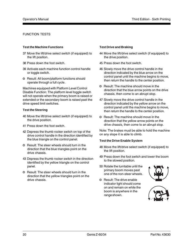
Test the Drive Enable System
48 Move the lift/drive select switch (if equipped) tothe lift position.
49 Press down the foot switch and lower the boomto the stowed position.
50 Rotate the turntable until theprimary boom moves pastone of the non-steer wheels.
Result: The drive enableindicator light should comeon and remain on while theboom is anywhere in therange shown.
FUNCTION TESTS
Test the Machine Functions
37 Move the lift/drive select switch (if equipped) tothe lift position.
38 Press down the foot switch.
39 Activate each machine function control handleor toggle switch.
Result: All boom/platform functions shouldoperate through a full cycle.
Machines equipped with Platform Level ControlDisable Function: The platform level toggle switchwill not operate when the primary boom is raised orextended or the secondary boom is raised past thedrive speed limit switches.
Test the Steering
40 Move the lift/drive select switch (if equipped) tothe drive position.
41 Press down the foot switch.
42 Depress the thumb rocker switch on top of thedrive control handle in the direction identified bythe blue triangle on the control panel.
Result: The steer wheels should turn in thedirection that the blue triangles point on thedrive chassis.
43 Depress the thumb rocker switch in the directionidentified by the yellow triangle on the controlpanel.
Result: The steer wheels should turn in thedirection that the yellow triangles point on thedrive chassis.

Part No. 43630 Genie Z-60/34 21
Operator's ManualThird Edition · Sixth Printing
51 Move the lift/drive select switch (if equipped) tothe drive position.
52 Move the drive control handle off center.
Result: The drive function should not operate.
53 Move and hold the drive enable toggle switch toeither side and slowly move the drive controlhandle off center.
Result: The drive function should operate.
Note: When the drive enable system is in use, themachine may drive in the opposite direction that thedrive and steer control handle is moved.
Use the color-coded directionarrows on the platform controlsand the drive chassis toidentify the direction of travel.
Test Limited Drive Speed
54 Move the lift/drive select switch (if equipped) tothe lift position.
55 Press down the foot switch.
56 Raise the primary boom approximately2 feet / 61 cm.
57 Move the lift/drive select switch (if equipped) tothe drive position.
58 Slowly move the drive control handle to the fulldrive position.
Result: The maximum achievable drive speedwith the primary boom raised should not exceed1 foot / 30 cm per second.
59 Move the lift/drive select switch (if equipped) tothe lift position.
60 Lower the primary boom to the stowed position.
61 Extend the primary boom approximately2 ft / 61 cm.
62 Move the lift/drive select switch (if equipped) tothe drive position.
63 Slowly move the drive control handle to the fulldrive position.
Result: The maximum achievable drive speedwith the primary boom extended should notexceed 1 foot / 30 cm per second.
FUNCTION TESTS
Blue
Yellow
22 Genie Z-60/34 Part No. 43630
Operator's Manual Third Edition · Sixth Printing
64 Move the lift/drive select switch (if equipped) tothe lift position.
65 Retract the primary boom to the stowed position.
66 Raise the secondary boom approximately2 feet / 61 cm.
67 Move the lift/drive select switch (if equipped) tothe drive position.
68 Slowly move the drive control handle to the fulldrive position.
Result: The maximum achievable drive speedwith the secondary boom raised should notexceed 1 foot / 30 cm per second.
69 Move the lift/drive select switch (if equipped) tothe lift position.
70 Lower the secondary boom to the stowedposition.
Note: If the drive speed with the primary boomraised or extended or the secondary boom raisedexceeds 1 foot / 30 cm per second, immediatelytag and remove the machine from service.
FUNCTION TESTS
Test Auxiliary Controls
71 Shut the engine off.
72 Pull out the red Emergency Stop button tothe ON position.
73 Move the lift/drive select switch (if equipped) tothe lift position.
74 Press down the foot switch.
75 Simultaneously hold the auxiliary power switchon and activate each function control handle ortoggle switch.
Note: To conserve battery power, test eachfunction through a partial cycle.
Result: All boom and steer functions shouldoperate. Drive functions should not operate withauxiliary power.
Test the Lift/Drive Select Switch(if equipped)
76 Move the lift/drive select switch (if equipped) tothe lift position.
77 Press down the foot switch.
78 Move the drive control handle off center.
Result: The drive function should not operate.
79 Activate each boom function toggle switch.
Result: All boom functions should operate.
80 Move the lift/drive select switch (if equipped) tothe drive position.
81 Press down the foot switch.
82 Activate each boom function toggle switch.
Result: The boom functions should not operate.
83 Move the drive control handle off center.
Result: The drive function should operate.
84 Repair any malfunctions before operating themachine.
Part No. 43630 Genie Z-60/34 23
Operator's ManualThird Edition · Sixth Printing
Workplace Inspection
Workplace InspectionBe aware of and avoid the following hazardoussituations:
· drop-offs or holes
· bumps, floor obstructions or debris
· overhead obstructions and high voltageconductors
· hazardous locations
· inadequate surface support to withstand all loadforces imposed by the machine
· wind and weather conditions
· the presence of unauthorized personnel
· other possible unsafe conditions
Do Not Operate Unless:
You learn and practice the principles of safemachine operation contained in this operator'smanual.
1 Avoid hazardous situations.
2 Always perform a pre-operationinspection.
3 Always perform function tests prior to use.
4 Inspect the workplace.
Know and understand the workplaceinspection before going on to the nextsection.
5 Only use the machine as it was intended.
FundamentalsThe Workplace Inspection helps the operatordetermine if the workplace is suitable for safemachine operation. It should be performed by theoperator prior to moving the machine to theworkplace.
It is the operator's responsibility to read andremember the workplace hazards, then watch forand avoid them while moving, setting up andoperating the machine.
24 Genie Z-60/34 Part No. 43630
Operator's Manual Third Edition · Sixth Printing
Operating Instructions
Do Not Operate Unless:
You learn and practice the principles of safemachine operation contained in this operator'smanual.
1 Avoid hazardous situations.
2 Always perform a pre-operationinspection.
3 Always perform function tests prior touse.
4 Inspect the workplace.
5 Only use the machine as it was intended.
FundamentalsThe Operating Instructions section providesinstructions for each aspect of machine operation.It is the operator's responsibility to follow all thesafety rules and instructions in the operator's,safety and responsibilities manuals.
Using the machine for anything other than liftingpersonnel and tools to an aerial work site is unsafeand dangerous.
Only trained and authorized personnel should bepermitted to operate a machine. If more than oneoperator is expected to use a machine at differenttimes in the same work shift, they must all bequalified operators and are all expected to follow allsafety rules and instructions in the operator's,safety and responsibilities manuals. That meansevery new operator should perform a pre-operationinspection, function tests, and a workplaceinspection before using the machine.
Part No. 43630 Genie Z-60/34 25
Operator's ManualThird Edition · Sixth Printing
Starting the Engine1 At the ground controls, turn the key switch to
the desired position.
2 Be sure both the ground and platform controlred Emergency Stop buttons are pulled out tothe ON position.
3 Gasoline/LPG models: Choose fuel by movingthe fuel select switch to the desired position.
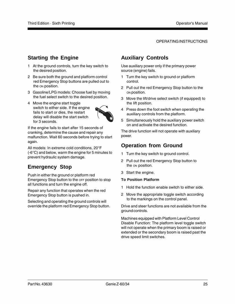
4 Move the engine start toggleswitch to either side. If the enginefails to start or dies, the restartdelay will disable the start switchfor 3 seconds.
If the engine fails to start after 15 seconds ofcranking, determine the cause and repair anymalfunction. Wait 60 seconds before trying to startagain.
All models: In extreme cold conditions, 20°F(-6°C) and below, warm the engine for 5 minutes toprevent hydraulic system damage.
Emergency StopPush in either the ground or platform redEmergency Stop button to the OFF position to stopall functions and turn the engine off.
Repair any function that operates when the redEmergency Stop button is pushed in.
Selecting and operating the ground controls willoverride the platform red Emergency Stop button.
Auxiliary ControlsUse auxiliary power only if the primary powersource (engine) fails.
1 Turn the key switch to ground or platformcontrol.
2 Pull out the red Emergency Stop button to theON position.
3 Move the lift/drive select switch (if equipped) tothe lift position.
4 Press down the foot switch when operating theauxiliary controls from the platform.
5 Simultaneously hold the auxiliary power switchon and activate the desired function.
The drive function will not operate with auxiliarypower.
Operation from Ground1 Turn the key switch to ground control.
2 Pull out the red Emergency Stop button tothe ON position.
3 Start the engine.
To Position Platform
1 Hold the function enable switch to either side.
2 Move the appropriate toggle switch accordingto the markings on the control panel.
Drive and steer functions are not available from theground controls.
Machines equipped with Platform Level ControlDisable Function: The platform level toggle switchwill not operate when the primary boom is raised orextended or the secondary boom is raised past thedrive speed limit switches.
OPERATING INSTRUCTIONS

26 Genie Z-60/34 Part No. 43630
Operator's Manual Third Edition · Sixth Printing
To Drive
1 Move the lift/drive select switch (if equipped) tothe drive position.
2 Press down the foot switch.
3 Increase speed: Slowly move the drive controlhandle off center.
Decrease speed: Slowly move the drive controlhandle toward the center.
Stop: Return the drive control handle to thecenter or release the foot switch.
Use the color-coded direction arrows on theplatform controls and the drive chassis to identifythe direction the machine will travel.
Machine travel speed is restricted when the boomsare raised or extended or the turntable is rotated.
Drive Enable
Light ON indicates that the primary boom has movedjust past either non-steer wheel and the drivefunction has been interrupted.
To drive, hold the drive enable switch to either sideand slowly move the drive control handle off center.
Be aware that the machine may move in theopposite direction that the drive and steer controlsare moved.
Always use the color-codeddirection arrows on theplatform controls and drivechassis to identify thedirection the machine willtravel.
OPERATING INSTRUCTIONS
Operation from Platform1 Turn the key switch to platform control.
2 Pull out both the ground and platform redEmergency Stop buttons to the ON position.
3 Start the engine. Do not press down the footswitch when starting the engine.
To Position Platform
1 Move the lift/drive select switch (if equipped) tothe lift position.
2 Press down the foot switch.
3 Slowly move the appropriate function controlhandle or toggle switch according to themarkings on the control panel.
Machines equipped with Platform Level ControlDisable Function: The platform level toggle switchwill not operate when the primary boom is raised orextended or the secondary boom is raised past thedrive speed limit switches.
To Steer
1 Move the lift/drive select switch (if equipped) tothe drive position.
2 Press down the foot switch.
3 Turn the steer wheels with the thumb rockerswitch located on top of the drive controlhandle.
Use the color-coded direction arrows on theplatform controls and the drive chassis to identifythe direction the wheels will turn.
Blue
Yellow

Part No. 43630 Genie Z-60/34 27
Operator's ManualThird Edition · Sixth Printing
OPERATING INSTRUCTIONS
Drive Speed Select
· Machine on incline symbol: Low range operationfor inclines
· Machine on level surface symbol: High rangeoperation for maximum drive speed
Engine Idle Select (rpm)Select engine idle (rpm) using the symbols on thecontrol panel.
· Rabbit and foot switch symbol:foot switch activated high idle
· Turtle symbol: low idle
· Rabbit symbol: high idle
Generator
To operate the generator, move the generatortoggle switch to the generator position. The enginewill continue to run but no drive or platformfunctions will operate.
Plug a power tool into the power to platform GFCIoutlet.
To resume machine functions, move the generatortoggle switch to the machine functions position. Allfunctions will operate.
Oscillating Axles (if equipped)Oscillating axles will lock out automatically whenthe boom is raised or extended, or the turntable isrotated.
Check Engine Light(if equipped)Light on and engine stopped: Tag the machine andremove from service.
Light on and engine still running: Contact servicepersonnel within 24 hours.
Stopping the EnginePush in the red Emergency Stop button and turnthe key switch to the OFF position.
After Each Use1 Select a safe parking location—firm level
surface, clear of obstruction and traffic.
2 Retract and lower the boom to the stowedposition.
3 Rotate the turntable so that the boom is betweenthe non-steer wheels.
4 Turn the key switch to the OFF position andremove the key to secure from unauthorizeduse.
5 Chock the wheels.

28 Genie Z-60/34 Part No. 43630
Operator's Manual Third Edition · Sixth Printing
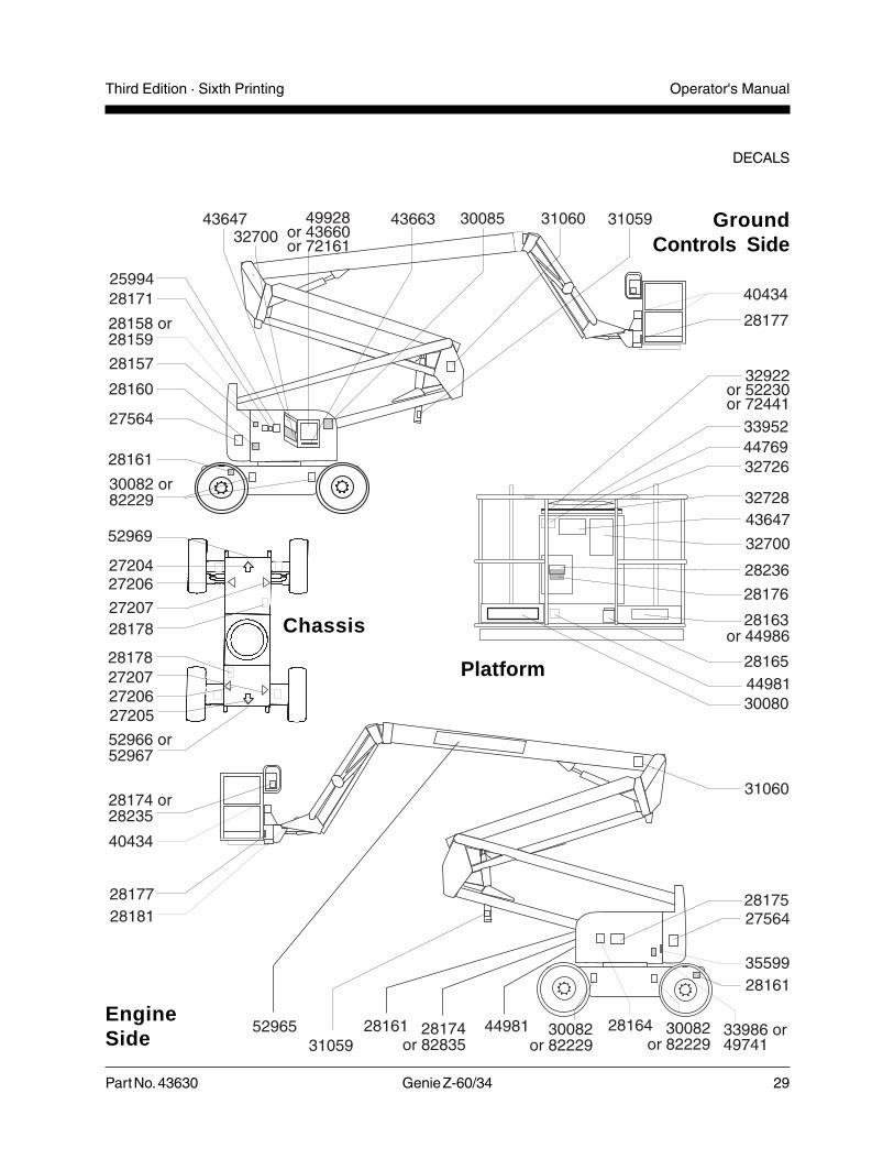
Decals
Part No. Decal Description Quantity
25994 Caution - Component Damage Hazard 1
27204 Arrow - Blue 1
27205 Arrow - Yellow 1
27206 Triangle- Blue 2
27207 Triangle - Yellow 2
27564 Danger - Electrocution Hazard 2
28157 Label - Dexron 1
28158 Label - Unleaded 1
28159 Label - Diesel 1
28160 Label - Liquid Petroleum Gas 2
28161 Danger - Crushing Hazard 3
28163 Notice - Maximum Side Force150 lbs / 667 N, ANSI & CSA 1
28164 Notice - Hazardous Materials 1
28165 Notice - Foot Switch 1
28171 Label - No Smoking 1
28174 Label - Power to Platform, 230V 2
28175 Caution - Compartment Access 1
28176 Notice - Missing Manuals 1
28177 Warning - Platform Rotate 2
28178 Warning - Shear Point 2
28181 Warning - No Step or Ride 1
28235 Label - Power to Platform, 115V 2
28236 Warning - Failure To Read . . . 1
30080 Notice - Maximum Load 500 lbs / 227 kg 1
30082 Notice - Tire Specifications 4
31059 Warning - Collision 2
31060 Danger - Tip-over Hazard, Interlock 2
Part No. Decal Description Quantity
32700 Danger - General Safety Rules 2
32726 Label - Glow Plug (option) 1
32728 Label - Generator (option) 1
32922 Platform Control Panel 1
33952 Danger - Tilt-Alarm 1
33986 Notice - Deutz Diesel Engine Specs 1
35599 Notice - Align Air Hoses 1
40434 Label - Lanyard Anchorage 3
43647 Notice - Operating Instructions 2
43660 Ground Control Panel 1
43663 Notice - Function Enable 1
49741 Notice - Ford Engine Specs-LRG-425 EFI 1
44769 Label - Lift/Drive Select (option) 1
44981 Label - Air Line to Platform 2
44986 Notice - Maximum Manual Force90 lbs / 400 N, CE 1
49928 Ground Control Panel 1
52230 Platform Control Panel 1
52966 Cosmetic - 4 x 2 1
52967 Cosmetic - 4 x 4 1
52965 Cosmetic - Genie Z-60/34 1
52969 Cosmetic - Genie Boom 1
72161 Ground Control Panel 1
72441 Platform Control Panel 1
82229 Notice, Tire Specifications 4
Decal InspectionUse the pictures on the next page to verifythat all decals are legible and in place.
Below is a numerical list with quantities anddescriptions.
Part No. 43630 Genie Z-60/34 29
Operator's ManualThird Edition · Sixth Printing
DECALS
EngineSide
GroundControls Side
Chassis
Platform

30 Genie Z-60/34 Part No. 43630
Operator's Manual Third Edition · Sixth Printing
BrakeDisengage
BrakeEngage
1
Securing to Truck or Trailer forTransitAlways use the turntable rotation lock each timethe machine is transported.
Always chock the machine wheels in preparationfor transport.
Use the tie points on the drive chassis foranchoring down to the transport surface.
Use chains or straps of ample load capacity.
2
Observe and Obey:
The transport vehicle must be parked on a levelsurface.
The transport vehicle must be secured toprevent rolling while the machine is beingloaded.
Be sure the vehicle capacity and loadingsurfaces are sufficient to support the machineweight. See Specifications section.
Use the lower platform mount between the boomend and the platform to secure the boom from side-to-side movement. Do not use excessivedownward force when securing the boom section.
Turn the key switch to the OFF position and removethe key before transporting.
Inspect the entire machine for loose or unsecureditems.
Free-wheel Configuration forWinchingChock the wheels to prevent the machine fromrolling.
Release the non-steer wheel brakes by turning overthe torque hub disconnect caps (detail 1).
4WD models: Open the pump free-wheel valveby turning counterclockwise two turns (detail 2).
Be sure the winch line is properly secured to thedrive chassis tie points and the path is clear of allobstruction.
Reverse the procedures described for details 1 and2 to re-engage the brakes.
2WD models: The pump free-wheel valve shouldalways remain closed.
Note: Towing the Genie Z-60/34 is notrecommended. If the machine must be towed, donot exceed 2 mph / 3.2km/h.
Transport Instructions

Part No. 43630 Genie Z-60/34 31
Operator's ManualThird Edition · Sixth Printing
Specifications
Model 2WD 2WD/4WDIndustrial Rough Terrain
Height, working maximum 66 ft 66 ft20.1m 20.1m
Height, platform maximum 60 ft 60 ft18.3 m 18.3 m
Height, stowed maximum 8 ft 1 in 8 ft 4 in2.4 m 2.5 m
Horizontal reach maximum 34 ft 34 ft10.4 m 10.4 m
Width 7 ft 7 ft 6 in2.1 m 2.3 m
Length, stowed 26 ft 26 ft7.9 m 7.9 m
Maximum load capacity 500 lbs 500 lbs6 foot platform 227 kg 227 kg
Maximum load capacity 500 lbs 500 lbs8 foot platform 227 kg 227 kg
Wheelbase 7 ft 11 in 7 ft 9 in2.41 m 2.36 m
Turning radius (outside) 13.5 ft 19.5 ft4.1 m 5.9 m
Turning radius (inside) 4 ft 11 ft1.2 m 3.4 m
Turntable rotation (degrees) continuous
Turntable tailswing 0 0
Power source Ford 63 Hp Gasoline/LPG LRG-423(choice) or LRG-425 EFI
Deutz 56 Hp Diesel F4L 1011
Drive speed, stowed 0 to 3.5 mph 0 to 4.5 mphgasoline/LPG models 0 to 5.6 km/h 0 to 7.2 km/h
Drive speed, stowed 0 to 3.0 mph 0 to 3.9 mphDeutz Diesel models 0 to 4.8 km/h 0 to 6.3 km/h
Drive speed, 0 to 0.6 mph 0 to 0.6 mphbooms raised or 0 to 1.0 km/h 0 to 1.0 km/hextended - all models
Airborne noise emissions 80 dBMaximum sound level at normal operating workstations(A-weighted)
Model 2WD 2WD/4WDIndustrial Rough Terrain
Controls 12V DC proportional
Platform dimensions, 6 foot 30 x 72 in 30 x 72 in(width x length) 76 cm x 1.8 m 76 cm x 1.8 m
Platform dimensions, 8 foot 36 x 96 in 36 x 96 in(width x length) 91cm x 2.4 m 91cm x 2.4 m
Platform leveling self-leveling self-leveling
Platform rotation 180° 180°
AC outlet in platform standard standard
Hydraulic pressure, maximum 2500 psi 2500 psi(boom functions) 172 bar 172 bar
Tires 32 x 12-15 15 x 19.520-ply 12-ply
300-15
Gradeability, stowed 30% 20% / 35%
Ground clearance 9 in 12 in23 cm 30 cm
Fuel tank capacity 20 gallons 20 gallons76 liters 76 liters
Weight See Serial Plate(Machine weights vary with option configurations)
0 ft 10 ft 20 ft 30 ft 40 ft
70 ft21.4m
60 ft18.3m
50 ft15.3m
40 ft12.2m
30 ft9.2m
20 ft6.1m
10 ft3.1m
0 ft0m
Continuous improvement of our products is a Geniepolicy. Product specifications are subject to changewithout notice or obligation.

Genie North America
Genie Australia Pty Ltd.
Genie China
Genie Malaysia
Genie Japan
Genie Korea
Genie Africa
Genie Latin America
Phone
Toll Free
Fax
Phone +
Fax +
Phone +
Fax +
Phone +
Fax +
Phone +
Fax +
Phone +
Fax +
Phone +
Fax +
Phone +
Fax +
425.881.1800
USA and Canada
800.536.1800
425.883.3475
61 7 3375 1660
61 7 3375 1002
86 21 53852570
86 21 53852569
60 4 228 1235
60 4 226 6872
81 3 3453 6082
81 3 3453 6083
82 2 558 7267
82 2 558 3910
27 11 455 0373
27 11 455 0355
55 11 4055 2499
55 11 4043 1661 Dis
trib
ute
dB
y:
California Proposition 65
WARNINGThe exhaust from this product contains chemicals
known to the State of California to cause cancer,
birth defects or other reproductive harm.
Genie Holland
Genie Scandinavia
Genie France
Genie Iberica
Genie Germany
Genie U.K.
Genie Mexico City
Phone +
Fax +
Phone +
Fax +
Phone +
Fax +
Phone +
Fax +
Phone +
Fax +
Phone +
Fax +
Phone +
Fax +
31 70 51 78836
31 70 51 13993
46 31 3409612
33 (0)2 37 26 09 99
33 (0)2 37 26 09 98
34 93 579 5042
34 93 579 5059
49 (0)4202 88520
49 (0)4202 8852-20
44 (0)1476 584333
44 (0)1476 584334
52 55 5666 5242
52 55 5666 3241
46 31 3409613