Operator's Manual Sixth Edition • First...
43
-
Upload
truongliem -
Category
Documents
-
view
225 -
download
1
Transcript of Operator's Manual Sixth Edition • First...


Operator's Manual Sixth Edition • First Printing
Z-34/22 • Z-34/22N Part No. 1258814
Copyright © 1996 by Genie Industries
Sixth Edition: First Printing, July 2014
"Genie" and "Z" are registered trademarks ofGenie Industries in the U.S.A. and many othercountries.
These machines comply withANSI A92.5CSA B354.4
Complies with EC Directive 2006/42/EC See EC Declaration of Conformity
Printed on recycled paper
Printed in U.S.A.
Important
Read, understand and obey these safety rules andoperating instructions before operating this machine.Only trained and authorized personnel shall bepermitted to operate this machine. This manual shouldbe considered a permanent part of your machine andshould remain with the machine at all times. If youhave any questions, call Genie.
Contents
PageSafety Rules .............................................................. 1Controls .................................................................... 10Legend ...................................................................... 12Pre-operation Inspection ........................................... 13Maintenance ............................................................. 15Function Tests .......................................................... 18Workplace Inspection ................................................ 23Operating Instructions ............................................... 24Transport and Lifting Instructions .............................. 31Decals ...................................................................... 34Specifications ........................................................... 38
Contact us:
Internet: http://www.genielift.come-mail: [email protected]

Operator's ManualSixth Edition • First Printing
Part No. 1258814 Z-34/22 • Z-34/22N 1
Safety Rules
Danger
Failure to obey the instructions andsafety rules in this manual will resultin death or serious injury.
Do Not Operate Unless:
You learn and practice the principles of safemachine operation contained in this operator'smanual.
1 Avoid hazardous situations.
Know and understand the safety rulesbefore going on to the next section.
2 Always perform a pre-operation inspection.
3 Always perform function tests prior to use.
4 Inspect the workplace.
5 Only use the machine as it was intended.
You read, understand and obey themanufacturer's instructions and safety rules—safety and operator's manuals and machinedecals.
You read, understand and obey employer'ssafety rules and worksite regulations.
You read, understand and obey all applicablegovernmental regulations.
You are properly trained to safely operate themachine.

Operator's Manual Sixth Edition • First Printing
2 Z-34/22 • Z-34/22N Part No. 1258814
SAFETY RULES
Electrocution Hazards
This machine is not electrically insulated and willnot provide protection from contact with orproximity to electrical current.
Maintain safe distances from electrical power linesand apparatus in accordance with applicablegovernmental regulations and the following chart.
Voltage Minimum SafePhase to Phase Approach Distance
Feet Meters
0 to 300V Avoid Contact
300V to 50KV 10 3.05
50KV to 200KV 15 4.60
200KV to 350KV 20 6.10
350KV to 500KV 25 7.62
500KV to 750KV 35 10.67
750KV to 1000KV 45 13.72
Allow for platform movement, electrical line sway orsag and beware of strong or gusty winds.
Keep away from the machine if it contactsenergized power lines. Personnel on the ground orin the platform must not touch or operate themachine until energized power lines are shut off.
Do not operate the machine during lightning orstorms.
Do not use the machine as a ground for welding.
Tip-over Hazards
Occupants, equipment and materials shall notexceed the maximum platform capacity.
Maximum platform capacity 500 lbs 227 kg
Maximum platform capacity
Machine equipped withAircraft Protection Package 440 lbs 200 kg
Maximum occupants 2
The weight of options and accessories, such aspipe cradles, panel cradles and welders, will reducethe rated platform capacity and must be factoredinto the total platform load. See the decals on theoptions.

Operator's ManualSixth Edition • First Printing
Part No. 1258814 Z-34/22 • Z-34/22N 3
CE and Australia Markets: Do not use air-filledtires. These machines are equipped withfoam-filled tires. Wheel weight and propercounterweight configuration are critical to stability.
Do not raise or extend the boom unless themachine is on a firm, level surface.
Do not depend on the tilt alarm as a level indicator.The tilt alarm sounds in the platform only when themachine is on a severe slope.
If the tilt alarm sounds while the boom is lowered:Do not extend, rotate or raise the boom abovehorizontal. Move the machine to a firm, levelsurface before raising the platform.
3
3
ANSI, CSA and AUS models: If the tilt alarmsounds when the platform is raised: Use extremecaution. Identify the condition of the boom on theslope as shown below. Follow the steps to lowerthe boom before moving to a firm, level surface. Donot rotate the boom while lowering.
CE models: If the tilt alarm sounds when theplatform is raised, use extreme caution. TheMachine Not Level indicator light will come on andthe drive function in one or both directions will notoperate. Identify the condition of the boom on theslope as shown below. Follow the steps to lowerthe boom before moving to a firm, level surface. Donot rotate the boom while lowering.
All models: If the tilt alarmsounds with the platform uphill:
1 Lower the primary boom.
2 Lower the secondary boom.
3 Retract the primary boom.
If the tilt alarm sounds with theplatform downhill:
1 Retract the primaryboom.
2 Lower the secondaryboom.
3 Lower the primaryboom.
SAFETY RULES

Operator's Manual Sixth Edition • First Printing
4 Z-34/22 • Z-34/22N Part No. 1258814
SAFETY RULES
Do not drive the machine on or near uneven terrain,unstable surfaces or other hazardous conditionswith the boom raised or extended.
Do not drive the machine on a slope that exceedsthe maximum uphill, downhill or side slope rating ofthe machine. Slope rating applies only to machinesin the stowed position.
Z-34/22N, Maximum slope rating, stowed position
Counterweight uphill 35% 19°
Counterweight downhill 20% 11°
Side slope 25% 14°
Z-34/22 DC, Maximum slope rating, stowed position
Counterweight uphill 30% 17°
Counterweight downhill 20% 11°
Side slope 25% 14°
Note: Slope rating is subject to ground conditionsand adequate traction.
Do not push off or pull toward any object outsideof the platform.
Maximum allowableside force - ANSI &CSA150 lbs / 667 N
Maximum allowablemanual force - CE90 lbs / 400 N
Do not alter or disable the limit switches.
Do not drive over 0.7 mph / 1 km/h with the primaryboom raised or extended or the secondary boomraised.
Do not use the platform controls to free a platformthat is caught, snagged or otherwise preventedfrom normal motion by an adjacent structure. Allpersonnel must be removed from the platformbefore attempting to free the platform using theground controls.
Do not raise the boom when wind speeds mayexceed 28 mph / 12.5 m/s. If wind speeds exceed28 mph / 12.5 m/s when the boom is raised, lowerthe boom and do not continue to operate themachine.
Do not operate the machine in strong or gustywinds. Do not increase the surface area of theplatform or the load. Increasing the area exposed tothe wind will decrease machine stability.
Use extreme care and slow speeds while drivingthe machine in the stowed position across uneventerrain, debris, unstable or slippery surfaces andnear holes and drop-offs.

Operator's ManualSixth Edition • First Printing
Part No. 1258814 Z-34/22 • Z-34/22N 5
Do not use batteries that weigh less than theoriginal equipment. Batteries are used ascounterweight and are critical to machine stability.Each battery must weigh a minimum of88 lbs / 40 kg. Each battery box including batteriesmust weigh a minimum of 452 lbs / 205 kg..
Do not use the machine as a crane.
Do not push the machine or other objects with theboom.
Do not contact adjacent structures with the boom.
Do not tie the boom or platform to adjacentstructures.
Do not place loads outside the platform perimeter.
Do not alter or disable machine components that inany way affect safety and stability.
Do not replace items critical to machine stabilitywith items of different weight or specification.
Do not modify or alter an aerial work platformwithout prior written permission from themanufacturer. Mounting attachments for holdingtools or other materials onto the platform, toeboardsor guard rail system can increase the weight in theplatform and the surface area of the platform or theload.
Do not place or attach overhanging loads to anypart of this machine.
Do not place ladders or scaffolds in the platform oragainst any part of this machine.
Do not transport tools and materials unless they areevenly distributed and can be safely handled byperson(s) in the platform.
Do not use the machine on a moving or mobilesurface or vehicle.
Be sure all tires are in good condition and lug nutsare properly tightened.
SAFETY RULES

Operator's Manual Sixth Edition • First Printing
6 Z-34/22 • Z-34/22N Part No. 1258814
Fall Hazards
Occupants must wear asafety belt or harness andcomply with applicablegovernmental regulations.Attach lanyard to the anchorprovided in the platform.
Do not sit, stand or climb on the platform guardrails. Maintain a firm footing on the platform floor atall times.
Do not climb down from the platform when raised.
Keep the platform floor clear of debris.
Lower the platform entry mid-rail or close the entrygate before operating.
Do not enter or exit the platform unless themachine is in the stowed position and the platformis at ground level.
Collision Hazards
Be aware of limited sightdistance and blind spotswhen driving or operating.
Be aware of the boom position when rotating theturntable.
Check the work area for overhead obstructions orother possible hazards.
Be aware of crushing hazards when grasping theplatform guard rail.
Operators must comply with employer, job site andgovernmental rules regarding the use of personalprotective equipment.
Observe and use the color-coded direction arrowson the platform controls and drive chassis for driveand steer functions.
SAFETY RULES
Operator's ManualSixth Edition • First Printing
Part No. 1258814 Z-34/22 • Z-34/22N 7
SAFETY RULES
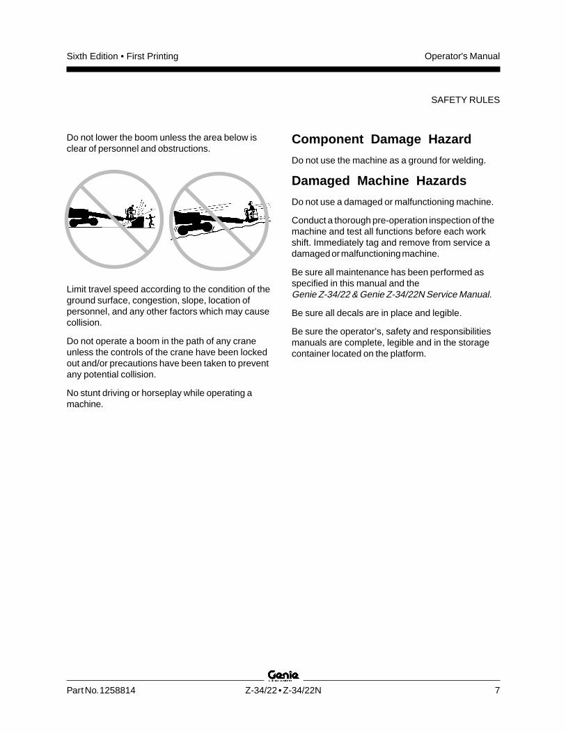
Do not lower the boom unless the area below isclear of personnel and obstructions.
Limit travel speed according to the condition of theground surface, congestion, slope, location ofpersonnel, and any other factors which may causecollision.
Do not operate a boom in the path of any craneunless the controls of the crane have been lockedout and/or precautions have been taken to preventany potential collision.
No stunt driving or horseplay while operating amachine.
Component Damage Hazard
Do not use the machine as a ground for welding.
Damaged Machine Hazards
Do not use a damaged or malfunctioning machine.
Conduct a thorough pre-operation inspection of themachine and test all functions before each workshift. Immediately tag and remove from service adamaged or malfunctioning machine.
Be sure all maintenance has been performed asspecified in this manual and theGenie Z-34/22 & Genie Z-34/22N Service Manual.
Be sure all decals are in place and legible.
Be sure the operator’s, safety and responsibilitiesmanuals are complete, legible and in the storagecontainer located on the platform.
Operator's Manual Sixth Edition • First Printing
8 Z-34/22 • Z-34/22N Part No. 1258814
Bodily Injury Hazard
Do not operate the machine with a hydraulic oil orair leak. An air leak or hydraulic leak can penetrateand/or burn skin.
Improper contact with components under anycover will cause serious injury. Only trainedmaintenance personnel should accesscompartments. Access by the operator is onlyadvised when performing a pre-operationinspection. All compartments must remain closedand secured during operation.
SAFETY RULES
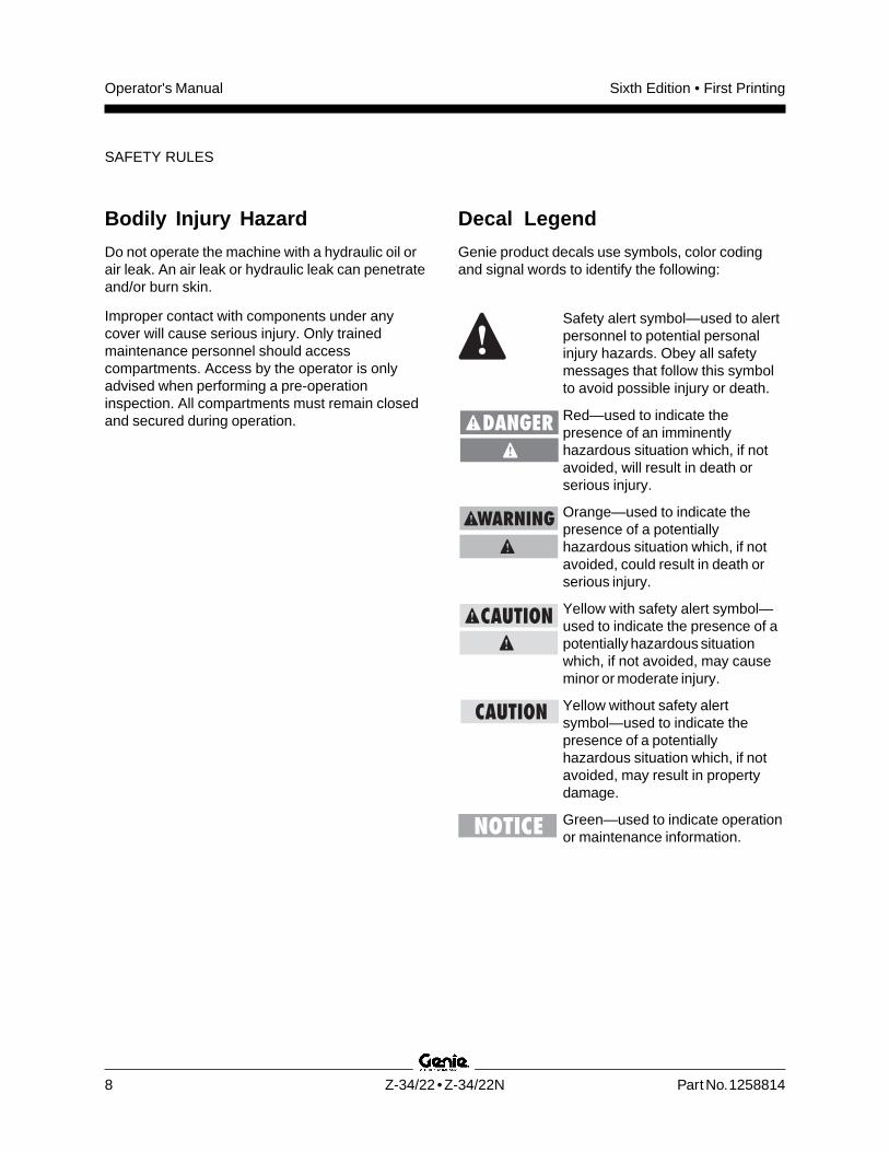
Decal Legend
Genie product decals use symbols, color codingand signal words to identify the following:
Safety alert symbol—used to alertpersonnel to potential personalinjury hazards. Obey all safetymessages that follow this symbolto avoid possible injury or death.
Red—used to indicate thepresence of an imminentlyhazardous situation which, if notavoided, will result in death orserious injury.
Orange—used to indicate thepresence of a potentiallyhazardous situation which, if notavoided, could result in death orserious injury.
Yellow with safety alert symbol—used to indicate the presence of apotentially hazardous situationwhich, if not avoided, may causeminor or moderate injury.
Yellow without safety alertsymbol—used to indicate thepresence of a potentiallyhazardous situation which, if notavoided, may result in propertydamage.
Green—used to indicate operationor maintenance information.

Operator's ManualSixth Edition • First Printing
Part No. 1258814 Z-34/22 • Z-34/22N 9
SAFETY RULES
Battery Safety
Burn Hazards
Batteries contain acid. Always wear protectiveclothing and eye wear when working with batteries.
Avoid spilling or contacting battery acid. Neutralizebattery acid spills with baking soda and water.
The battery pack must remain in upright position.
Do not expose the batteries or the charger to wateror rain.
Explosion Hazards
Keep sparks, flames andlighted tobacco away frombatteries. Batteries emit anexplosive gas.
The battery pack covermust remain off during theentire charging cycle.
Do not contact the battery terminals or the cableclamps with tools that may cause sparks.
Component Damage Hazards
Do not use any battery charger greater than 48V tocharge the batteries.
Both battery packs must be charged together.
Disconnect the battery pack plug before removingthe battery pack.
Electrocution Hazards
Connect the battery charger toa grounded, AC 3-wireelectrical outlet only.
Inspect daily for damaged cord,cables and wires. Replacedamaged items beforeoperating.
Avoid electrical shock from contact with batteryterminals. Remove all rings, watches and otherjewelry.
Tip-over Hazard
Do not use batteries that weigh less than theoriginal equipment. Batteries are used ascounterweight and are critical to machine stability.Each battery must weigh a minimum of88 lbs / 40 kg. Each battery box including batteriesmust weigh a minimum of 452 lbs / 205 kg.
Lifting Hazard
Use a forklift to remove or install the battery packs.

Operator's Manual Sixth Edition • First Printing
10 Z-34/22 • Z-34/22N Part No. 1258814
Controls
Platform Control Panel
1 Drive enable switch
2 Drive enable indicator light
3 ANSI/CSA models:Auxiliary power switchCE models:Auxiliary power switch with cover
4 Platform level switch
5 Horn button
6 Primary boom extend/retract switch
7 Red Emergency Stop button
8 Function override - Aircraft protection package(if equipped)
9 Battery charge indicator and/or low voltageinterrupt (option)
10 Machine not level indicator light (if equipped)
11 Proportional control handle for drive function andthumb rocker for steer function
12 Platform overload indicator light (if equipped)
13 Boom function speed controller
14 Jib boom up/down switch
15 Secondary boom up/down switch
16 Primary boom up/down switch
17 Turntable rotate switch
18 Platform rotate switch
19 Not used
To drive, hold drive enable
switch up or down and
slowly move drive control
handle. Machine may drive
in opposite direction that
the drive and steer controls
are moved.
Use color-coded direction
arrows on this panel and
drive chassis to identify the
direction machine will travel.
Light on indicates that boom
has moved past a non-steer
tire and drive function is
turned off.
DRIVE
ENABLE
OPERATION
STOP
F
E
12
CREEP
19 18 17 16 13 15 14 20 20
20
20
20
12
11
10987654
3
2
1

Operator's ManualSixth Edition • First Printing
Part No. 1258814 Z-34/22 • Z-34/22N 11
CONTROLS
Ground Control Panel
1 Secondary boom up/down switch
2 Turntable rotate switch
3 Platform rotate switch
4 Platform level switch
5 Primary boom extend/retract switch
6 ANSI/CSA models:Auxiliary power switchCE models:Auxiliary power switch with cover
7 Key switch for platform/off/ground selection
8 Hour meter
9 Red Emergency Stop button
10 10A breaker for electrical circuits
11 Platform overload indicator light (if equipped)
12 Not used
13 Jib boom up/down switch
14 Primary boom up/down switch
15 Function enable switch
4
3
6
7
8
10
12
14
1
15
13
11
9
5
2
00009.9
STOP

Operator's Manual Sixth Edition • First Printing
12 Z-34/22 • Z-34/22N Part No. 1258814
1 Non-steer tire
2 Battery box
3 Steer tire
4 Power to charger (between steer tires)
5 Ground controls
6 Secondary boom
7 Primary boom
8 Jib boom
9 Platform controls
10 Platform
11 Lanyard anchorage point
12 Sliding mid-rail
13 Manual storage container
14 Foot switch
Legend

Operator's ManualSixth Edition • First Printing
Part No. 1258814 Z-34/22 • Z-34/22N 13
Pre-operation Inspection
Do Not Operate Unless:
You learn and practice the principles of safemachine operation contained in this operator'smanual.
1 Avoid hazardous situations.
2 Always perform a pre-operationinspection.
Know and understand the pre-operationinspection before going on to the nextsection.
3 Always perform function tests prior to use.
4 Inspect the workplace.
5 Only use the machine as it was intended.
Fundamentals
It is the responsibility of the operator to perform apre-operation inspection and routine maintenance.
The pre-operation inspection is a visual inspectionperformed by the operator prior to each work shift.The inspection is designed to discover if anythingis apparently wrong with a machine before theoperator performs the function tests.
The pre-operation inspection also serves todetermine if routine maintenance procedures arerequired. Only routine maintenance items specifiedin this manual may be performed by the operator.
Refer to the list on the next page and check eachof the items.
If damage or any unauthorized variation fromfactory delivered condition is discovered, themachine must be tagged and removed fromservice.
Repairs to the machine may only be made by aqualified service technician, according to themanufacturer's specifications. After repairs arecompleted, the operator must perform apre-operation inspection again before going on tothe function tests.
Scheduled maintenance inspections shall beperformed by qualified service technicians,according to the manufacturer's specifications andthe requirements listed in the responsibilitiesmanual.

Operator's Manual Sixth Edition • First Printing
14 Z-34/22 • Z-34/22N Part No. 1258814
Pre-operation Inspection
Be sure that the operator's, safety andresponsibilities manuals are complete, legibleand in the storage container located on theplatform.
Be sure that all decals are legible and in place.See Decals section.
Check for hydraulic oil leaks and proper oillevel. Add oil if needed. See Maintenancesection.
Check for battery fluid leaks and proper fluidlevel. Add distilled water if needed. SeeMaintenance section.
Z-34/22: Check for proper tire pressure. Add airif needed. See Maintenance section.
Check the following components or areas fordamage, improperly installed or missing parts andunauthorized modifications:
Electrical components, wiring and electricalcables
Hydraulic power unit, tank, hoses,fittings, cylinders and manifolds
Drive and turntable motors and drive hubs
Boom wear pads
Tires and wheels
Limit switches, alarms and horn
Nuts, bolts and other fasteners
Platform entry mid-rail bar or gate
Beacon and alarms (if equipped)
Lanyard anchorage points
PRE-OPERATION INSPECTION
Check entire machine for:
Cracks in welds or structural components
Dents or damage to machine
Be sure that all structural and other criticalcomponents are present and all associatedfasteners and pins are in place and properlytightened.
Be sure that both battery packs are in place,latched and properly connected.
After you complete your inspection, be sure thatall compartment covers are in place andlatched.

Operator's ManualSixth Edition • First Printing
Part No. 1258814 Z-34/22 • Z-34/22N 15
Maintenance
Observe and Obey:Only routine maintenance items specified in thismanual shall be performed by the operator.
Scheduled maintenance inspections shall becompleted by qualified service technicians,according to the manufacturer's specificationsand the requirements specified in theresponsibilities manual.
Dispose of material in accordance withgovernmental regulations.
Maintenance Symbols Legend
The following symbols have beenused in this manual to helpcommunicate the intent of theinstructions. When one or more ofthe symbols appear at thebeginning of a maintenanceprocedure, it conveys the meaningbelow.
Indicates that tools will be required toperform this procedure.
Indicates that new parts will berequired to perform this procedure.
Check the Hydraulic Oil Level
Maintaining the hydraulic oil at the proper level isessential to machine operation. Improper hydraulicoil levels can damage hydraulic components. Dailychecks allow the inspector to identify changes in oillevel that might indicate the presence of hydraulicsystem problems.
1 Be sure that the boom is in the stowed position.
2 Check the hydraulic oil level.
Result: The hydraulic oil level should be,between the FULL and ADD marks on thehydraulic tank.
3 Add hydraulic oil if necessary.
Hydraulic Oil Specifications
Hydraulic oil type Chevron Rando HDPremium MV equivalent

Operator's Manual Sixth Edition • First Printing
16 Z-34/22 • Z-34/22N Part No. 1258814
Check the Batteries
Proper battery condition is essential to goodmachine performance and operational safety.Improper fluid levels or damaged cables andconnections can result in component damage andhazardous conditions.
Electrocution/burn hazard. Contactwith hot or live circuits could resultin death or serious injury. Removeall rings, watches and otherjewelry.
Bodily injury hazard. Batteriescontain acid. Avoid spilling orcontacting battery acid. Neutralizebattery acid spills with baking sodaand water.
Perform this test after fullycharging the batteries.
1 Put on protective clothing and eye wear.
2 Be sure that the battery cable connections aretight and free of corrosion.
Standard Batteries
3 Remove the battery vent caps.
4 Check the battery acid level. If necessary,replenish with distilled water to the bottom ofthe battery fill tube. Do not overfill.
5 Install the vent caps.
MAINTENANCE
Check the Tire Pressure
This procedure does not needto be performed on machinesequipped with the foam-filled orsolid tires.
Bodily injury hazard. An over-inflated tire can explode and maycause death or serious injury.
Tip-over hazard. Do not usetemporary flat tire repair products.
To safeguard maximum stability, achieveoptimum machine handling and minimize tirewear, it is essential to maintain proper pressurein all air-filled tires.
1 Check each tire with an air pressure gauge andadd air as needed.
Tire pressure
Industrial tire 100 psi 6.89 bar

Operator's ManualSixth Edition • First Printing
Part No. 1258814 Z-34/22 • Z-34/22N 17
Scheduled Maintenance
Maintenance performed quarterly, annually andevery two years must be completed by a persontrained and qualified to perform maintenance onthis machine according to the procedures found inthe service manual for this machine.
Machines that have been out of service for morethan three months must receive the quarterlyinspection before they are put back into service.
MAINTENANCE

Operator's Manual Sixth Edition • First Printing
18 Z-34/22 • Z-34/22N Part No. 1258814
Function Tests
Do Not Operate Unless:
You learn and practice the principles of safemachine operation contained in this operator'smanual.
1 Avoid hazardous situations.
2 Always perform a pre-operationinspection.
3 Always perform function tests prior touse.
Know and understand the function testsbefore going on to the next section.
4 Inspect the workplace.
5 Only use the machine as it was intended.1 Select a test area that is firm, level and free of
obstruction.
At the Ground Controls
2 Turn the key switch to ground control.
3 Pull out the red Emergency Stop button tothe on position.
Result: The beacon (if equipped) should flash.
Test Emergency Stop
4 Push in the red Emergency Stop button to theoff position.
Result: All ground and platform control functionsshould not operate.
5 Pull out the red Emergency Stop button tothe on position.
Fundamentals
The function tests are designed to discover anymalfunctions before the machine is put intoservice. The operator must follow the step-by-stepinstructions to test all machine functions.
A malfunctioning machine must never be used. Ifmalfunctions are discovered, the machine must betagged and removed from service. Repairs to themachine may only be made by a qualified servicetechnician, according to the manufacturer’sspecifications.
After repairs are completed, the operator mustpreform a pre-operation inspection and functiontests again before putting the machine into service.

Operator's ManualSixth Edition • First Printing
Part No. 1258814 Z-34/22 • Z-34/22N 19
FUNCTION TESTS
At the Platform Controls
11 Turn the key switch to platform control.
12 Pull out the red Emergency Stop button tothe on position.
Result: The beacon (if equipped) should flash.
Test Emergency Stop
13 Push in the platform red Emergency Stop buttonto the off position.
Result: All platform control functions should notoperate.
Test the Boom Functions
6 Do not hold the function enableswitch to either side. Attempt toactivate each boom and platformfunction toggle switch.
Result: All boom and platform functions shouldnot operate.
7 Hold the function enable switch to either sideand activate each boom and platform functiontoggle switch.
Result: All boom and platform functions shouldoperate through a full cycle. The descent alarm(if equipped) should sound while the boom islowering.
Test the Tilt Sensor
8 Pull out the platform red Emergency Stopbutton to the on position. Turn the key switch toplatform control.
9 Open the ground control side turntable coverand locate the tilt sensor next to the functionmanifold.
10 Press down one side of the tiltsensor.
Result: The alarm, located in theplatform, should sound.

Operator's Manual Sixth Edition • First Printing
20 Z-34/22 • Z-34/22N Part No. 1258814
FUNCTION TESTS
Test the Horn
14 Pull out the red Emergency Stop button to theon position.
15 Push the horn button.
Result: The horn should sound.
Test the Foot Switch
16 Do not press down the foot switch. Activateeach machine function.
Result: The machine functions should notoperate.
Test Machine Functions
17 Press down the foot switch.
18 Activate each machine function toggle switch.
Result: All boom and platform functions shouldoperate through a full cycle.
Note: Control the speed of boom functions byadjusting the boom function speed controller. Driveand steer functions are not affected by the boomfunction speed controller.
Test the Steering
19 Press down the foot switch.
20 Depress the thumb rocker switch on top of thedrive control handle in the direction identified bythe blue triangle on the control panel.
Result: The steer wheels should turn in thedirection that the blue triangles point on thedrive chassis.
21 Depress the thumb rocker switch in the directionidentified by the yellow triangle on the controlpanel.
Result: The steer wheels should turn in thedirection that the yellow triangles point on thedrive chassis.

Operator's ManualSixth Edition • First Printing
Part No. 1258814 Z-34/22 • Z-34/22N 21
Test Drive and Braking
22 Press down the foot switch.
23 Slowly move the drive control handle in thedirection indicated by the blue arrow on thecontrol panel until the machine begins to move,then return the handle to the center position.
Result: The travel alarm should sound. Themachine should move in the direction that theblue arrow points on the drive chassis, thencome to an abrupt stop.
24 Slowly move the drive control handle in thedirection indicated by the yellow arrow on thecontrol panel until the machine begins to move,then return the handle to the center position.
Result: The travel alarm should sound. Themachine should move in the direction that theyellow arrow points on the drive chassis, thencome to an abrupt stop.
Note: The brakes must be able to hold the machineon any slope it is able to climb.
Test Limited Drive Speed
25 Press down the foot switch.
26 Raise the primary boom 1 foot / 30 cm.
27 Slowly move the drive control handle to the fulldrive position.
Result: The maximum achievable drive speedwith the primary boom raised should not exceed1 foot / 30 cm per second.
28 Lower the boom to the stowed position.
29 Raise the secondary boom 1 foot / 30 cm.
30 Slowly move the drive control handle to the fulldrive position.
Result: The maximum achievable drive speedwith the secondary boom raised should notexceed 1 foot / 30 cm per second.
31 Lower the boom to the stowed position.
32 Extend the primary boom 1 foot / 30 cm.
33 Slowly move the drive control handle to the fulldrive position.
Result: The maximum achievable drive speedwith the primary boom extended should notexceed 1 foot / 30 cm per second.
If the drive speed with the primary boom raised orextended or the secondary boom raised exceeds1 foot / 30 cm per second, immediately tag andremove the machine from service.
FUNCTION TESTS

Operator's Manual Sixth Edition • First Printing
22 Z-34/22 • Z-34/22N Part No. 1258814
FUNCTION TESTS
Test the Drive Enable System
34 Press down the foot switch and retract theprimary boom to the stowed position.
35 Rotate the turntable until the boom moves pastone of the non-steer wheels.
Result: The drive enableindicator light should come onand remain on while theboom is anywhere in therange shown.
36 Move the drive control handle off center.
Result: The drive function should not operate.
37 Hold the drive enable toggle switch up or downand slowly move the drive control handle offcenter.
Result: The drive function should operate.
Note: When the drive enable system is in use, themachine may drive in the opposite direction that thedrive and steer control handle is moved.
Use the color-coded directionarrows on the platform controlsand the drive chassis toidentify the direction of travel.
Test the Lift/Drive Select Function(if equipped)
38 Press down the foot switch.
39 Move the drive control handle off center andactivate a boom function toggle switch.
Result: No boom functions should operate. Themachine will move in the direction indicated onthe control panel.
Blue
Yellow
Operator's ManualSixth Edition • First Printing
Part No. 1258814 Z-34/22 • Z-34/22N 23
Workplace Inspection
Workplace Inspection
Be aware of and avoid the following hazardoussituations:
· drop-offs or holes
· bumps, floor obstructions or debris
· sloped surfaces
· unstable or slippery surfaces
· overhead obstructions and high voltageconductors
· hazardous locations
· inadequate surface support to withstand all loadforces imposed by the machine
· wind and weather conditions
· the presence of unauthorized personnel
· other possible unsafe conditions
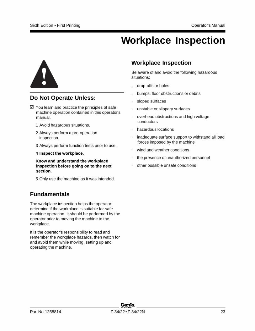
Do Not Operate Unless:
You learn and practice the principles of safemachine operation contained in this operator'smanual.
1 Avoid hazardous situations.
2 Always perform a pre-operationinspection.
3 Always perform function tests prior to use.
4 Inspect the workplace.
Know and understand the workplaceinspection before going on to the nextsection.
5 Only use the machine as it was intended.
Fundamentals
The workplace inspection helps the operatordetermine if the workplace is suitable for safemachine operation. It should be performed by theoperator prior to moving the machine to theworkplace.
It is the operator's responsibility to read andremember the workplace hazards, then watch forand avoid them while moving, setting up andoperating the machine.
Operator's Manual Sixth Edition • First Printing
24 Z-34/22 • Z-34/22N Part No. 1258814
Operating Instructions
Do Not Operate Unless:
You learn and practice the principles of safemachine operation contained in this operator'smanual.
1 Avoid hazardous situations.
2 Always perform a pre-operationinspection.
3 Always perform function tests prior to use.
4 Inspect the workplace.
5 Only use the machine as it was intended.
Fundamentals
The Operating Instructions section providesinstructions for each aspect of machine operation.It is the operator's responsibility to follow all thesafety rules and instructions in the operator's,safety and responsibilities manuals.
Using the machine for anything other than liftingpersonnel, along with their tools and materials, toan aerial work site is unsafe and dangerous.
Only trained and authorized personnel should bepermitted to operate a machine. If more than oneoperator is expected to use a machine at differenttimes in the same work shift, they must all bequalified operators and are all expected to follow allsafety rules and instructions in the operator's,safety and responsibilities manuals. That meansevery new operator should perform a pre-operationinspection, function tests, and a workplaceinspection before using the machine.

Operator's ManualSixth Edition • First Printing
Part No. 1258814 Z-34/22 • Z-34/22N 25
OPERATING INSTRUCTIONS
Emergency Stop
Push in the red Emergency Stop button to the offposition at the ground or platform controls to stopall machine functions.
Repair any function that operates when the redEmergency Stop button is pushed in.
Selecting and operating the ground controls willoverride the platform Red Emergency Stop button.
Auxiliary Controls
Use auxiliary power if the primary power sourcefails.
1 Be sure that both battery packs are connectedbefore operating the machine.
2 Turn the key switch to ground or platformcontrol.
3 Pull out the red Emergency Stop button to theon position.
4 Press down the foot switch when operating theauxiliary controls from the platform.
5 CE models: Break the security tie and lift thecover.
Note: If the security tie is broken or missing,consult the appropriate Genie service manual.
6 Simultaneously hold the auxiliarypower switch on and activate thedesired function.
The boom, steer and drive functions will operatewith auxiliary power.
Operation from Ground
1 Be sure both battery packs are connectedbefore operating the machine.
2 Turn the key switch to ground control.
3 Pull out the red Emergency Stop button tothe on position.
To Position Platform
1 Hold the function enable switch toeither side.
2 Move the appropriate toggle switch according tothe markings on the control panel.
Drive and steer functions are not available from theground controls.
Operation from Platform
1 Be sure that both battery packs are connectedbefore operating the machine.
2 Turn the key switch to platform control.
3 Pull out both ground and platform redEmergency Stop buttons to the on position.
To Position Platform
1 Set the boom function speed controller to thedesired speed.
Note: Drive and steer functions are not affected bythe boom function speed controller.
2 Press down the foot switch.
3 Move the appropriate toggle switch according tothe markings on the control panel.

Operator's Manual Sixth Edition • First Printing
26 Z-34/22 • Z-34/22N Part No. 1258814
To Steer
1 Press down the foot switch.
2 Turn the steer wheels with the thumb rockerswitch located on top of the drive controlhandle.
Use the color-coded direction triangles on theplatform controls and the drive chassis to identifythe direction the wheels will turn.
To Drive
1 Press down the foot switch.
2 Increase speed: Slowly move the drive controlhandle off center.
Decrease speed: Slowly move the drive controlhandle toward center.
Stop: Return the drive control handle to centeror release the foot switch.
Use the color-coded direction arrows on theplatform controls and the drive chassis to identifythe direction the machine will travel.
Machine travel speed is restricted when thebooms are raised or extended.
Battery condition will affect machine performance.
Driving on a slope
Determine the uphill, downhill and side slope ratingsfor the machine and determine the slope grade.
Maximum slope rating,counterweight uphill (gradeability):Z-34/22N: 35% (19°)Z-34/22 DC: 30% (17°)
Maximum slope rating, counterweightdownhill: 20% (11°)
Maximum side slope rating: 25% (14°)
Note: Slope rating is subject to ground conditionsand adequate traction. The term gradeability appliesto the counterweight uphill configuration only.
Be sure the boom is below horizontal and theplatform is between the non-steer wheels.
OPERATING INSTRUCTIONS
Operator's ManualSixth Edition • First Printing
Part No. 1258814 Z-34/22 • Z-34/22N 27
To determine the slope grade:
Measure the slope with a digital inclinometer ORuse the following procedure.
You will need:
carpenter’s level
straight piece of wood, at least 3 feet / 1 m long
tape measure
Lay the piece of wood on the slope.
At the downhill end, lay the level on the top edge ofthe piece of wood and lift the end until the piece ofwood is level.
While holding the piece of wood level, measure thedistance from the bottom of the piece of wood tothe ground.
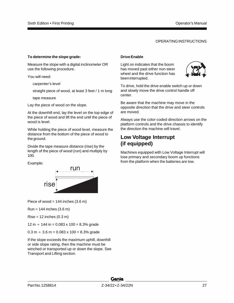
Divide the tape measure distance (rise) by thelength of the piece of wood (run) and multiply by100.
Example:
Piece of wood = 144 inches (3.6 m)
Run = 144 inches (3.6 m)
Rise = 12 inches (0.3 m)
12 in 144 in = 0.083 x 100 = 8.3% grade
0.3 m 3.6 m = 0.083 x 100 = 8.3% grade
If the slope exceeds the maximum uphill, downhillor side slope rating, then the machine must bewinched or transported up or down the slope. SeeTransport and Lifting section.
Drive Enable
Light on indicates that the boomhas moved past either non-steerwheel and the drive function hasbeen interrupted.
To drive, hold the drive enable switch up or downand slowly move the drive control handle offcenter.
Be aware that the machine may move in theopposite direction that the drive and steer controlsare moved.
Always use the color-coded direction arrows on theplatform controls and the drive chassis to identifythe direction the machine will travel.
Low Voltage Interrupt(if equipped)
Machines equipped with Low Voltage Interrupt willlose primary and secondary boom up functionsfrom the platform when the batteries are low.
OPERATING INSTRUCTIONS
Operator's Manual Sixth Edition • First Printing
28 Z-34/22 • Z-34/22N Part No. 1258814
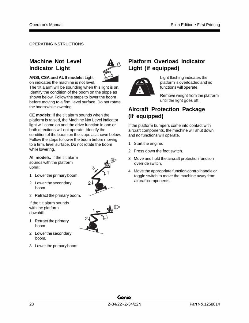
Machine Not LevelIndicator Light
ANSI, CSA and AUS models: Lighton indicates the machine is not level.The tilt alarm will be sounding when this light is on.Identify the condition of the boom on the slope asshown below. Follow the steps to lower the boombefore moving to a firm, level surface. Do not rotatethe boom while lowering.
CE models: If the tilt alarm sounds when theplatform is raised, the Machine Not Level indicatorlight will come on and the drive function in one orboth directions will not operate. Identify thecondition of the boom on the slope as shown below.Follow the steps to lower the boom before movingto a firm, level surface. Do not rotate the boomwhile lowering.
All models: If the tilt alarmsounds with the platformuphill:
1 Lower the primary boom.
2 Lower the secondaryboom.
3 Retract the primary boom.
If the tilt alarm soundswith the platformdownhill:
1 Retract the primaryboom.
2 Lower the secondaryboom.
3 Lower the primary boom.
OPERATING INSTRUCTIONS
Platform Overload IndicatorLight (if equipped)
Light flashing indicates theplatform is overloaded and nofunctions will operate.
Remove weight from the platformuntil the light goes off.
Aircraft Protection Package(If equipped)
If the platform bumpers come into contact withaircraft components, the machine will shut downand no functions will operate.
1 Start the engine.
2 Press down the foot switch.
3 Move and hold the aircraft protection functionoverride switch.
4 Move the appropriate function control handle ortoggle switch to move the machine away fromaircraft components.
3
3
Operator's ManualSixth Edition • First Printing
Part No. 1258814 Z-34/22 • Z-34/22N 29
Fall Protection
Personal fall protection equipment (PFPE) isrequired when operating this machine.
All PFPE must comply with applicablegovernmental regulations, and must be inspectedand used in accordance with the PFPEmanufacturer’s instructions.
After Each Use
1 Select a safe parking location—firm levelsurface, clear of obstruction and traffic.
2 Lower the boom to the stowed position.
3 Rotate the turntable so that the boom is betweenthe non-steer wheels.
4 Turn the key switch to the off position andremove the key to secure from unauthorizeduse.
5 Charge the batteries.
OPERATING INSTRUCTIONS
Operator's Manual Sixth Edition • First Printing
30 Z-34/22 • Z-34/22N Part No. 1258814
OPERATING INSTRUCTIONS
Battery and Charger Instructions
Observe and Obey:
Do not use external charger or booster batteries.
Charge the batteries in a well-ventilated area.
Use proper AC input voltage for charging asindicated on the charger.
Use only Genie authorized batteries andcharger.
To Charge the Batteries
1 Be sure the batteries are connected beforecharging the batteries.
2 Open the battery compartment. Thecompartment should remain open for the entirecharging cycle.
Maintenance-free batteries
1 Connect the battery charger to a grounded ACcircuit.
2 The charger will indicate when the battery is fullycharged.
Standard Batteries
1 Remove the battery vent caps and check thebattery acid level. If necessary, add onlyenough distilled water to cover the plates. Donot overfill prior to the charge cycle.
2 Replace the battery vent caps.
3 Connect the battery charger to a grounded ACcircuit.
4 The charger will indicate when the battery is fullycharged.
5 Check the battery acid level when the chargingcycle is complete. Replenish with distilled waterto the bottom of the fill tube. Do not overfill.
Dry Battery Filling and ChargingInstructions
1 Remove the battery vent caps and permanentlyremove the plastic seal from the battery ventopenings.
2 Fill each cell with battery acid (electrolyte) untilthe level is sufficient to cover the plates.
Do not fill to maximum level until the battery chargecycle is complete. Overfilling can cause the batteryacid to overflow during charging. Neutralize batteryacid spills with baking soda and water.
3 Install the battery vent caps.
4 Charge the battery.
5 Check the battery acid level when the chargingcycle is complete. Replenish with distilled waterto the bottom of the fill tube. Do not overfill.
Operator's ManualSixth Edition • First Printing
Part No. 1258814 Z-34/22 • Z-34/22N 31
Transport and Lifting Instructions
Observe and Obey:The transport vehicle must be parked on a levelsurface.
The transport vehicle must be secured toprevent rolling while the machine is beingloaded.
Be sure the vehicle capacity, loading surfacesand chains or straps are sufficient to withstandthe machine weight. See the serial plate for themachine weight.
The machine must be on a level surface orsecured before releasing the brakes.
Do not drive the machine on a slope thatexceeds the slope or side slope rating. SeeDriving on a Slope in the Operating Instructionssection.
If the slope of the transport vehicle bed exceedsthe uphill or downhill maximum slope rating, themachine must be loaded and unloaded using awinch as described.
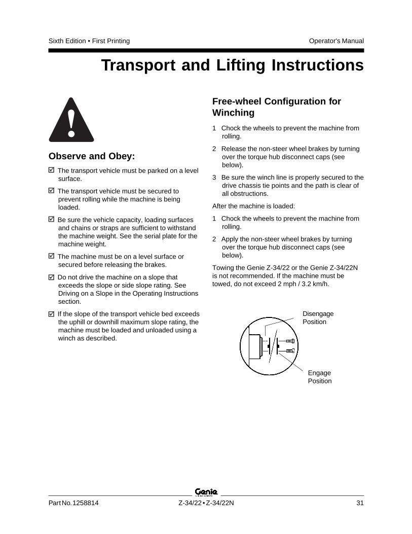
Free-wheel Configuration forWinching
1 Chock the wheels to prevent the machine fromrolling.
2 Release the non-steer wheel brakes by turningover the torque hub disconnect caps (seebelow).
3 Be sure the winch line is properly secured to thedrive chassis tie points and the path is clear ofall obstructions.
After the machine is loaded:
1 Chock the wheels to prevent the machine fromrolling.
2 Apply the non-steer wheel brakes by turningover the torque hub disconnect caps (seebelow).
Towing the Genie Z-34/22 or the Genie Z-34/22Nis not recommended. If the machine must betowed, do not exceed 2 mph / 3.2 km/h.
DisengagePosition
EngagePosition

Operator's Manual Sixth Edition • First Printing
32 Z-34/22 • Z-34/22N Part No. 1258814
Securing to Truck or Trailer forTransit
Always chock the machine wheels in preparationfor transport.
Turn the key switch to the off position and removethe key before transporting.
Inspect the entire machine for loose or unsecureditems.
Securing the Chassis
Use the tie points on the drive chassis foranchoring down to the transport surface.
Use chains or straps of ample load capacity.
Use a minimum of 4 chains.
Adjust the rigging to prevent damage to the chains.
Securing the Platform
Make sure the jib and platform are in the stowedposition.
Place a block under the edge of the platformbeneath the platform entry.
Secure the platform with a nylon strap placed overthe platform mount near the platform rotator (seebelow). Do not use excessive downward forcewhen securing the boom section.
TRANSPORT AND LIFTING INSTRUCTIONS

Operator's ManualSixth Edition • First Printing
Part No. 1258814 Z-34/22 • Z-34/22N 33
Observe and Obey:Only qualified riggers should rig and lift themachine.
Be sure the crane capacity, loading surfacesand straps or lines are sufficient to withstandthe machine weight. See the serial plate for themachine weight.
Lifting Instructions
Fully lower and retract the boom. Fully lower thejib. Remove all loose items on the machine.
Determine the center of gravity of your machineusing the table and the picture on this page.
Attach the rigging only to the designated liftingpoints on the machine. There are four lifting pointson the chassis.
Adjust the rigging to prevent damage to themachine and to keep the machine level.
Model Z-34/22 Z-34/22N
X Axis 30.7 in 34 in74.6 cm 86.3 cm
Y Axis 38.8 in 32 in98.6 cm 81.2 cm
TRANSPORT AND LIFTING INSTRUCTIONS

Operator's Manual Sixth Edition • First Printing
34 Z-34/22 • Z-34/22N Part No. 1258814
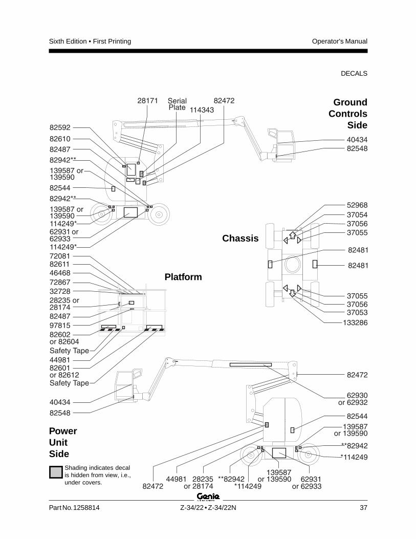
Decals
Part No. Decal Description Quantity
27564 Danger - Electrocution Hazard 2
28161 Warning - Crushing Hazard 3
28164 Notice - Hazardous Materials 1
28165 Notice - Foot Switch 1
28171 Label - No Smoking 1
28174 Label - Power to Platform, 230V 2
28175 Caution - Compartment Access 1
28176 Notice - Missing Manuals 1
28177 Warning - Platform Rotate 2
28181 Warning - No Step or Ride 1
28235 Label - Power to Platform, 115V 2
28236 Warning - Failure To Read . . . 1
28372 Caution - Component Damage 2
31060 Danger - Tip-over Hazard, Interlock 4
31508 Notice - Power to Charger 1
31784** Notice - Tire Specifications, Z-34/22 DC 4
31785 Notice - Battery Charger Instructions 2
31788 Danger - Battery/Charger Safety 2
32728 Label - Inverter Option Patch 1
35542 Notice - Tire Specifications, Z-34/22N 4
37052 Notice - Maximum Load, 500 lbs / 227 kg 1
37053 Arrow - Blue 1
37054 Arrow - Yellow 1
37055 Triangle - Blue 2
37056 Triangle - Yellow 2
40299 Notice - Battery Connection Diagram 2
40300 Danger - Tip-over, Batteries 2
40434 Label - Lanyard Anchorage 2
Part No. Decal Description Quantity
43595* Danger - Tip-over Hazard, Tires(Z-34/22 DC only) 4
44248 Label - Maximum Capacity, 440 lbs(Aircraft Protection Package) 1
44980 Label - Power to Charger, EE 1
44981 Label - Air Line to Platform 2
44986 Notice - Max Manual Force, 90 lbs / 400 N 1
46468 Label - Function Override(Aircraft Protection Package) 1
52947 Notice - Operating Instructions, Ground 1
52968 Cosmetic - Genie Boom 1
62930 Cosmetic - Genie Z-34/22 1
62931 Cosmetic - Genie Z-34/22 DC Power 2
62932 Cosmetic - Genie Z-34/22N 1
62933 Cosmetic - Genie Z-34/22N 2
65171 Label - Circuit Breaker & Status Light 1
65301* Notice - Tire Specifications, Z-34/22 DC 4
72081 Platform Control Panel 1
72833 Label - Open 2
72867 Label - Work Lights Option Patch 1
72999 Label - Environ MV46 1
82161 Label - UCON Hydrolube, HP-5046 1
82366 Label - Chevron Rando 1
82592 Ground Control Panel 1
97890 Danger - Safety Rules 2
97893 Notice - Max Side Force, 150 lbs / 667 N 1
114397 Danger - Tilt-Alarm 1
133286 Label - Power to Charger, Universal 1
139587 Label - Wheel Load, Z-34/22 DC 4
139590 Label - Wheel Load, Z-34/22N 4
1000043 Notice - Operating Instructions, Platform 1
Inspection for Decals with WordsDetermine whether the decals on your machinehave words or symbols. Use the appropriateinspection to verify that all decals are legible and inplace.
* Australia market only** ANSI market only

Operator's ManualSixth Edition • First Printing
Part No. 1258814 Z-34/22 • Z-34/22N 35
2816144981
97890
28372
43595*
72833
31060
65171
40299
4029931785
3178531508
40300
40300
31788
31788
3106028164
28171
52947
SerialPlate82592
28181
28177
37053
37054
52968
37056
3705528175
37055
37056
31060
28177
97890
40434
40434
114397
72081
1000043
2823628176
28165
27564
28161
82366or 82161or 72999
31060
44981
44980or 133286
62930or 62932
28235or 28174
35542or**31784or*65301
62931or 62933 28372
97893 or44986
28235 or28174
28161
139587 or139590
27564
35542 or31784**or65301*
*43595
35542or**31784or*65301
139587or 139590
*43595
32728
72867
35542 or31784**or65301*
139587 or139590
43595*72833
62931 or62933
37052or 44248
46468
GroundControls
Side
PowerUnitSide
Shading indicates decalis hidden from view, i.e.,under covers.
Platform
Chassis
DECALS

Operator's Manual Sixth Edition • First Printing
36 Z-34/22 • Z-34/22N Part No. 1258814
DECALS
Inspection for Decals withSymbolsDetermine whether the decals on your machinehave words or symbols. Use the appropriateinspection to verify that all decals are legible and inplace.
Part No. Decal Description Quantity
28171 Label - No Smoking 1
28174 Label - Power to Platform, 230V 2
28235 Label - Power to Platform, 115V 2
32728 Label - Inverter Option Patch 1
37053 Arrow - Blue 1
37054 Arrow - Yellow 1
37055 Triangle - Blue 2
37056 Triangle - Yellow 2
40434 Label - Lanyard Anchorage 2
44981 Label - Air Line to Platform 2
46468 Label - Function Override(Aircraft Protection Package) 1
52968 Cosmetic - Genie Boom 1
62930 Cosmetic - Genie Z-34/22 1
62931 Cosmetic - Genie Z-34/22 DC Power 2
62932 Cosmetic - Genie Z-34/22N 1
62933 Cosmetic - Genie Z-34/22N 2
72081 Platform Control Panel 1
72867 Label - Work Lights Option Patch 1
82472 Warning - Crushing Hazard 3
Part No. Decal Description Quantity
82481 Danger - Battery Safety 2
82487 Label - Operating Instructions 2
82544 Danger - Electrocution Hazard 2
82548 Warning - Platform Rotate 2
82592 Ground Control Panel 1
82601 Danger - Maximum Capacity, 227 kg 1
82602 Danger - Maximum Side Force, 667 N 1
82604 Danger - Maximum Manual Force, 400 N 1
82610 Label - Circuit Breaker & Status Light 1
82611 Label - Drive Enable Patch 1
82612 Label - Maximum Capacity, 200 kg(Aircraft Protection Package) 1
82942** Label - Tire Pressure, (Z-34/22 DC only) 4
97815 Label - Lower Mid-rail 1
114249* Danger - Tip-over Hazard, Tires(Z-34/22 DC only) 4
114343 Label - Emergency Lowering 1
133286 Label - Power to Charger 1
139587 Label - Wheel Load, Z-34/22 DC 4
139590 Label - Wheel Load, Z-34/22N 4
* CE market only** ANSI market only
Operator's ManualSixth Edition • First Printing
Part No. 1258814 Z-34/22 • Z-34/22N 37
62931 or62933
82610
82481
82481
82487
SerialPlate
82592
82548
37053
37054
52968
37056
37055
37055
37056
8254840434
40434
72081
82487
97815
82544
82472
8247244981
44981
133286
62930or 62932
28235or 28174
62931or 62933
139587or 139590
139587or 139590
82602or 82604
28235 or28174
82472
82544
82611
*114249**82942
**82942
*114249
28171
114343
82942**
139587 or139590
114249*
139587 or139590
82942**
114249*
72867
32728
Safety Tape
Safety Tape
46468
82601or 82612
GroundControls
Side
PowerUnitSide
Shading indicates decalis hidden from view, i.e.,under covers.
Platform
Chassis
DECALS

Operator's Manual Sixth Edition • First Printing
38 Z-34/22 • Z-34/22N Part No. 1258814
Specifications
Z-34/22N
Height, working maximum 40 ft 6 in 12.5 m
Height, platform maximum 34 ft 6 in 10.5 m
Height, stowed maximum 6 ft 7 in 2 m
Horizontal reach maximum 22 ft 3 in 6.8 m
Width 4 ft 10 in 1.5 m
Length, stowed 18 ft 9 in 5.7 m
Maximum load capacity 500 lbs 227 kg
Maximum wind speed 28 mph 12.5 m/s
Wheelbase 6 ft 2 in 1.9 m
Turning radius (outside) 13 ft 5 in 4.1 m
Turning radius (inside) 7 ft 2.1 m
Ground clearance 5 in 12.7 cm
Turntable rotation (degrees) 355°
Turntable tailswing 0
Power source 8 Group 902, J305,6V 315AH Batteries
Drive speeds, maximum
Boom stowed 4.0 mph 6.4 km/h40 ft/6.8 sec12.2 m/6.8 sec
Boom 0.6 mph 1.0 km/hraised or extended 40 ft/40 sec 12.2 m/40 sec
Controls 24V DC proportional
Platform dimensions, 56 in x 30 in(length x width) 1.42 m x 76 cm
Platform leveling self-leveling
Platform rotation 160°
AC outlet in platform standard
Hydraulic pressure, maximum 2800 psi(boom functions) 193 bar
System voltage 48V
Tires size, solid rubber 22 x 7 x 173/4 in
Total vibration value to which the hand/arm system issujected does not exceed 2.5 m/s2
Highest root mean square value of weightedacceleration to which the whole body is subjected doesnot exceed 0.5 m/s2
Weight See Serial Plate(Machine weights vary with option configurations)
Maximum slope rating, stowed position
Counterweight uphill 35% 19°
Counterweight downhill 20% 11°
Side slope 25% 14°
Note: Slope rating is subject to ground conditions andadequate traction.
Airborne noise emissions
Sound pressure level at ground workstation < 70 dBA
Sound pressure level at platform workstation < 70 dBA
Floor Loading Information
Tire load, maximum 6450 lbs 2926 kg
Tire contact pressure (per tire) 103 psi 7.24 kg/cm2
710 kPa
Occupied floor pressure 308 psf 14.75 kPa1504 kg/m2
Note: Floor loading information is approximate anddoes not incorporate different option configurations. Itshould be used only with adequate safety factors.
Continuous improvement of our products is aGenie policy. Product specifications are subjectto change without notice or obligation.

Operator's ManualSixth Edition • First Printing
Part No. 1258814 Z-34/22 • Z-34/22N 39
Z-34/22
Height, working maximum 40 ft 6 in 12.5 m
Height, platform maximum 34 ft 6 in 10.5 m
Height, stowed maximum 6 ft 7 in 2 m
Horizontal reach maximum 22 ft 3 in 6.8 m
Width 5 ft 8 in 1.7 m
Length, stowed 18 ft 6 in 5.6 m
Maximum load capacity 500 lb 227 kg
Maximum wind speed 28 mph 12.5 m/s
Wheelbase 6 ft 2 in 1.9 m
Turning radius (outside) 13 ft 1 in 4 m
Turning radius (inside) 5 ft 9 in 1.8 m
Ground clearance 6 in 15 cm
Turntable rotation (degrees) 355°
Turntable tailswing 0
Power source 8 Group 902, J305,6V 315AH Batteries
Drive speeds, maximum
Boom stowed, 4 mph 6.4 km/h40 ft/6.8 sec12.2 m/6.8 sec
Booms 0.6 mph 1.0 km/hraised or extended 40 ft/40 sec 12.2 m/40 sec
Controls 24V DC proportional
Platform dimensions, 56 in x 30 in(length x width) 1.42 m x 76 cm
Platform leveling self-leveling
Platform rotation 160°
AC outlet in platform standard
Hydraulic pressure, maximum 2800 psi(boom functions) 193 bar
System voltage 48V
Tires size, ANSI Size 9-14.5 LT
Tire size, CE and AustraliaFoam filled only 9-14.5
Total vibration value to which the hand/arm system issujected does not exceed 2.5 m/s2
Highest root mean square value of weightedacceleration to which the whole body is subjected doesnot exceed 0.5 m/s2
Weight See Serial Plate(Machine weights vary with option configurations)
Maximum slope rating, stowed position
Counterweight uphill 30% 17°
Counterweight downhill 20% 11°
Side slope 25% 14°
Note: Slope rating is subject to ground conditions andadequate traction.
Airborne noise emissions
Sound pressure level at ground workstation < 70 dBA
Sound pressure level at platform workstation < 70 dBA
Floor Loading Information
Tire load, maximum 5850 lbs 2654 kg
Tire contact pressure (per tire) 100 psi 7.03 kg/cm2
689 kPa
Occupied floor pressure 239 psf 11.44 kPa1167 kg/m2
Note: Floor loading information is approximate anddoes not incorporate different option configurations. Itshould be used only with adequate safety factors.
Continuous improvement of our products is aGenie policy. Product specifications are subjectto change without notice or obligation.
SPECIFICATIONS

Operator's Manual Sixth Edition • First Printing
40 Z-34/22 • Z-34/22N Part No. 1258814
SPECIFICATIONS
Range of Motion
0 ft0 m
0 ft0 m
5 ft1.5 m
5 ft1.52 m
15 ft4.6 m
15 ft4.6 m
20 ft6.1 m
25 ft7.6 m
20 ft6.1 m
25 ft7.6 m
30 ft9.1 m
35 ft10.6 m
10 ft3 m
10 ft3 m
-72°
+75°-72°
+75°