OPERATOR‘S MANUAL The intelligent universal … · clino_e.doc Page 5 of 24 Pages 1 GENERAL 1.1...
24
WYLER AG Im Hölderli CH-8405 WINTERTHUR Switzerland Tel. 0041 (0) 52 233 66 66 Fax. 0041 (0) 52 233 20 53 Homepage: http://www.wylerag.com E-Mail: [email protected] OPERATOR‘S MANUAL The intelligent universal inclinometer
Transcript of OPERATOR‘S MANUAL The intelligent universal … · clino_e.doc Page 5 of 24 Pages 1 GENERAL 1.1...

WYLER AGIm HölderliCH-8405 WINTERTHURSwitzerland
Tel. 0041 (0) 52 233 66 66Fax. 0041 (0) 52 233 20 53
Homepage: http://www.wylerag.comE-Mail: [email protected]
OPERATOR‘S MANUAL
The intelligent universal inclinometer
clino_e.doc Page 2 of 24 Pages
Content
1 GENERAL 5 1.1 INTRODUCTION 5 1.2 DESCRIPTION 5 1.3 OPERATING INSTRUCTIONS
2 OPERATING ELEMENTS 6 2.1 GENERAL INFORMATION 6 2.2 FUNCTIONS IN DETAIL 7 2.3 BATTERY TEST / CHANGE OF BATTERY 8 2.4 FUNCTION CHECK 8 2.5 SET ABSOLUTE ZERO 8 2.6 CHANGE UNITS OF MEASUREMENT 9 2.7 CHANGE RELATIVE BASE / SAVE SET-UP 10 2.8 HOLD - FUNCTION 11 2.9 PRINT - FUNCTION. 11 2.10 CANCEL 11 2.11 RESET 12 2.12 DATA TRANSMISSION
3. APPLICATIONS 12 3.1. ABSOLUTE MEASUREMENT 12 3.2. RELATIVE MEASUREMENT 12 3.3 MEASUREMENT OF WIDE ANGLES
3.4. SWITCHING OFF
13
4. TECHNICAL SPECIFICATIONS 14 4.1 GENERAL 14 4.2 SPECIFICATIONS FOR PORT CONNECTION
14
5. INFRARED-ZAPPER / INFRARED RECEIVER 17 5.1 OPERATION 17 5.2 "TEACH-IN" OF THE IR-ZAPPER
17
6. SERVICE 18 6.1 CALIBRATION 18 6.2 ACCESSORIES / SPARE PARTS
19
7. STORAGE / CARE AND HANDLING OF THE BATTERIES
19
APPENDIX A Connecting wiring diagrams 19
APPENDIX B Attaching Clinotronic PLUS 22
APPENDIX C CLINOMASTER for the calibration of the CLINOTRONIC 22
APPENDIX D Repair of Measuring Instruments 23
APPENDIX E ERROR MESSAGES 23
Modifications:
Date Modified by Description of modifications 21.9.2006 HEH ClinotronicCLINOTRONIC PLUS new edition 27.6.2007 HEH Various modifications 24.7.2007 HEH/BRP New with USB connection and Infrared Zapper
21.11.2012 MG New error messages 26.4.2016 MG New unit %
clino_e.doc Page 3 of 24 Pages
INDEX Key word
A Chapter Page
Absolute measurement 3.1 12 Accessories / Spare parts 6.2 19 Applications 3 12 Automatic shut off deactivating 2.2 7
B 2.3 8 Battery 4.1 14 Battery / Care and handling of the batteries 7.2 19 Battery indication 2.2 8 Battery indicator 2.1 6 Battery life 4.1 14 Battery test / Change of Battery 2.3 8
C 6.2 19 Cable 2.5m with remote button 6.2 19 Calibration 4.1 14 Calibration 6.1 18 Calibration with master Appendix C 22 Cancel 2.10 11 CE conformity 4.1 14 Certificate Appendix C 22 Change relative base / save set-up 2.7 10 Change units of measurement 2.6 9 CLINOMASTER for the calibration of the CLINOTRONIC Appendix C 23 Connecting a remote button to the Clinotronic PLUS using the RS485 interface Appendix A 20 Connecting the Clinotronic PLUS to a computer with a RS232 interface using the RS485 interface of the instrument
Appendix A 21
Connecting the Clinotronic PLUS to a computer with a RS232 interface using the RS485 interface of the instrument / also a remote button installed
Appendix A 21
Connecting the Clinotronic PLUS to a computer with a RS422 interface using the RS485 interface of the instrument
Appendix A 21
Connecting the Clinotronic PLUS to a computer with a RS485 interface using the RS485 interface of the instrument
Appendix A 20
Connecting the Clinotronic PLUS to a computer with a RS485 interface using the RS485 interface of the instrument / also a remote button installed
Appendix A 20
Connection mode 4.2.3 15 Connection mode, polling, data exchange 4.2.3 15
D Data frame structure 4.2.3 16 Data transfer 4.2.1 14 Data Transmission 2.12 12 Description 1.2 5 Direction of the indicated inclination 2.2 7
E ENTER/HOLD key 2.1 6 ENTER/HOLD key 2.2 7 Express Repair Service, ERS Appendix D 23
F Function check 2.4 8 Functions in detail 2.2 7
G General 1 5 General information 2.1 6 General specifications 4.1 14
H HOLD - Function 2.8 11
I Important modifications compared with the previous model 1.1 5 Indication of inclination 2.1 6

clino_e.doc Page 4 of 24 Pages
Indication of inclination in selected units 2.1 6 Infrared-Zapper 5 17 Interface connector to PC (RS232) 6.2 19 Interface socket RS485 2.1 6 Interface socket RS485 2.2 8 Introduction 1.1 5
K KEY ECHO Visual indication "a key is depressed" 2.1 6
L Limits of error 4.1 14
M Magnets and threads 6.2 19 Magnets and threads Appendix B 22 Measurement of wide angles 3.3 13 Measuring bases 6.2 19 Measuring units 2.2 7 Measuring units 2.6 10
O ON/MODE key 2.1 6 ON/MODE key 2.2 7 Operating elements 2 6 Operating instructions 1.3 5
P Print - Function. 2.9 11
R Relative measurement 3.2 12 Repair of Measuring Instruments Appendix D 23 Reset 2.11 12 Resolution 4.1 14
S SELECT/PRINT key 2.1 6 SELECT/PRINT key 2.2 7 Selection pointer for operation modes 2.2 7 Service 6 18 Set absolute zero 2.5 8 Settle time 4.1 14 Shut off the instrument 3.4 13 Special cases of display units 2.6 9 Specifications for port connection 4.2 14 Storage 7 19
T TEACH-IN" of the IR-Zapper 5.2 17 Technical specifications 4 14 Temperature coefficient 4.1 14 Temperature range 4.1 14 Threads and magnetic inserts 6.2 19
W Weight 4.1 14

clino_e.doc Page 5 of 24 Pages
1 GENERAL 1.1 INTRODUCTION The electronic inclinometer Clinotronic PLUS is with regard to the appearance as well as to the functions quite similar to the predecessor CLINO 45. The internal technology was however completely redesigned and updated to the latest possible technology. Important modifications
More rugged and from the measurement's point of view more stable housing, 100 x 75 x 30 mm New sensor type New software for angular computing Standard batteries, no loss of calibration data when changing batteries. True RS485 – Interface / connections to various WYLER instruments as well as to a PC Initialisation of measurement with Infrared Zapper State of the art microelectronics incorporated. Faster sampling leads to more rapid display reply
Additional features, as up until now:
Possible range of measurement: ±10 / 30 / 45 / 60 Grad. Display of the measured values in all commonly used units. Simple selections by using the instruments
keys. Setting a relative base length and display of the values to this base. Automatic zero setting by using the respective keys. Absolute and relative measurements simple to set by using the keys. Calibration of the unit is easily possible using the built-in software (see Appendix C, Clinomaster). Inclination measurement in any quadrant is possible using one of the four precisely machined surfaces,
which form the square frame of the instrument. 1.2 DESCRIPTION The Clinotronic PLUS follows a new concept from base up and is an electronic inclinometer with unsurpassed versatility. Contained in the rugged and compact housing are: The precision inclination sensor, the custom developed microprocessor, the large LCD display unit, the operating elements and the interface socket. The Clinotronic PLUS provides a measuring capacity of ± 45 degree (upon requirement delivery is also possible with a measuring range of ± 10, ± 30 or ± 60 degrees). Four precisely machined surfaces assure accuracy and repeatability of measurements. Selectable by push-button, any units suitable for inclination may be applied to the display. Even slope indication based on a relative base of selectable length is possible. Simple push-button operation automatically sets absolute as well as relative zero. The interface sockets (RS 485) provided, will connect to a variety of other WYLER instruments like e.g. LEVELMETER 2000, T/C directly to a PC. All indicated values are, by integration of calibration values stored, computed prior to display. If required, an integrated calibration mode may be actuated in order to replace the stored calibration data. For this purpose, the Clinotronic PLUS must, with the aid of suitable equipment, be accurately inclined, using 5 deg. steps over the range of ± 50 deg. The measuring principle is based on a friction free suspended disc of mass weighing less than 1 gram. Two electrodes together with the disc supported between them, represent a differential capacitor. Changes of capacitance resulting because of disc displacement when the unit is inclined are detected by counting the frequency and after suitable evaluation are displayed in the selected units. Completely friction free pendulum supports in conjunction with damping by air displacement provide excellent accuracy in respect of repetition and hysteresis as well as rapid availability of values. 1.3 OPERATING INSTRUCTIONS Attentive study of these operating instructions, prior to first time use, will make you familiar with the multiple functions and possibilities of the Clinotronic PLUS. Faulty manipulations or at the worst, unintended loss of calibration data will then be prevented.
clino_e.doc Page 6 of 24 Pages
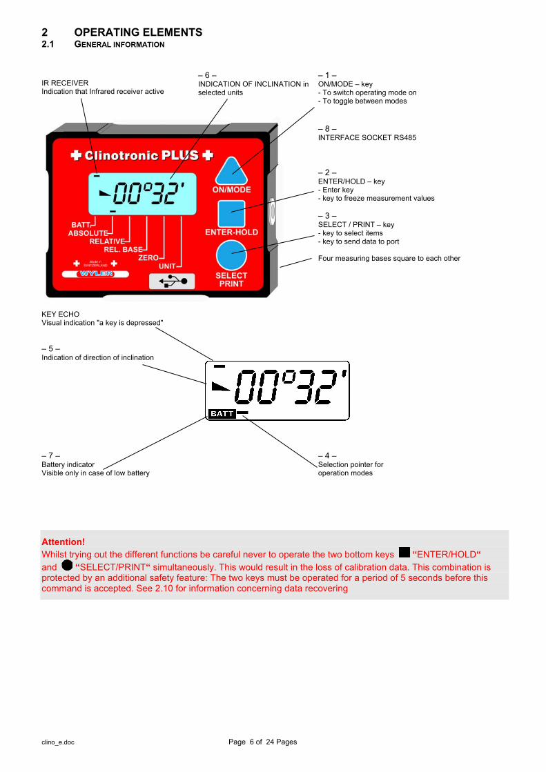
2 OPERATING ELEMENTS 2.1 GENERAL INFORMATION IR RECEIVER Indication that Infrared receiver active
– 6 – INDICATION OF INCLINATION in selected units
– 1 – ON/MODE – key - To switch operating mode on - To toggle between modes
– 8 – INTERFACE SOCKET RS485
– 2 – ENTER/HOLD – key - Enter key - key to freeze measurement values – 3 – SELECT / PRINT – key - key to select items - key to send data to port Four measuring bases square to each other
KEY ECHO Visual indication "a key is depressed"
– 5 – Indication of direction of inclination
– 7 – Battery indicator Visible only in case of low battery
– 4 – Selection pointer for operation modes
Attention! Whilst trying out the different functions be careful never to operate the two bottom keys “ENTER/HOLD“ and “SELECT/PRINT“ simultaneously. This would result in the loss of calibration data. This combination is protected by an additional safety feature: The two keys must be operated for a period of 5 seconds before this command is accepted. See 2.10 for information concerning data recovering

clino_e.doc Page 7 of 24 Pages
2.2 FUNCTIONS IN DETAIL
– 1 – ON/MODE Key Use this key to put the Clinotronic PLUS into operation. The Key ON/MODE must remain
pressed until all the display segments are visible. The Clinotronic PLUS thereafter automatically changes to the previously set operational mode. The display will show until the first valid measurement value is available.
When pressing the ON/MODE key for more than 3 seconds the display starts flashing and the automatic shut off is disabled. In the standard mode the instrument shut off after about 5 minutes. To turn off the instrument press the ON/MODE key for more than 3 seconds until the display disappears. Exception: In case the instrument is powered by an external power supply, the instrument is never shutting off automatically.
Attention! At this stage a display " " in flashing mode indicates loss of calibration data.
Possible cause: This may be due to accidental call of the calibration mode. (A protection through two key operation and 5 seconds command delay should prevent such accidents) or the calibration was started but not finished correctly. Chapter 5.1 contains instructions for recalibration. Possible data recovering according to chapter 2.10.
– 1 – ON/MODE Key For selection of different operation modes. Move the selection pointer - 4 - by operating this key.
– 2 – ENTER/HOLD Key Puts a selected operation mode into effect or enters a choice made by using the SELECT" key.
– 2 – ENTER/HOLD Key Use this key to "freeze" a measurement value. The hold function is particularly useful if
measurements have to be taken when the display is not visible. The Clinotronic PLUS will pause until two identical values are detected in succession (self sensing for motion). The valid indication will be displayed with flashing figures. Delete the indication by re-selecting HOLD function or by operating the SELECT/PRINT key or the ON/MODE key.
– 3 – SELECT/PRINT Key Use this key to select an option within an opened (selected) operation mode. E.g. Selection of
desired measurement unit within the operation mode "UNIT"; in case of digital input, selection of the value (0...9) of a digital position.
– 3 – SELECT/PRINT Key Cancel the HOLD – function
Sending a value to the port RS485
– 4 – Selection pointer for operation modes Serves as pointer for the selection of the different operation modes. Indicates the operation mode
currently in use: Absolute; relative; or measurements with respect to a relative base length; setting of absolute zero point. A flashing pointer indicates that an action by the operator is required. For example, whilst setting absolute zero point, the flashing pointer indicates that the input of the second measurement value is required.
– 5 – Indicator for direction of indication A comprehensive symbol indicates the direction of the indicated inclination.
Rising to the right. (positive inclination) Falling to the right. (negative inclination)
– 6 – Measuring units Indication of the measuring unit currently employed. A total of 15 possibilities (measuring units and
formats) are available (see also chapter 2.6).
clino_e.doc Page 8 of 24 Pages
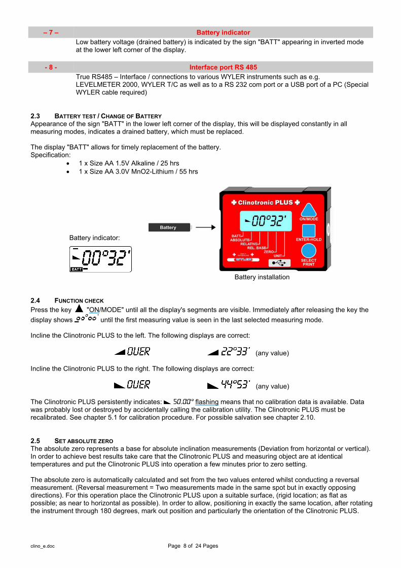
– 7 – Battery indicator
Low battery voltage (drained battery) is indicated by the sign "BATT" appearing in inverted mode at the lower left corner of the display.
- 8 - Interface port RS 485
True RS485 – Interface / connections to various WYLER instruments such as e.g. LEVELMETER 2000, WYLER T/C as well as to a RS 232 com port or a USB port of a PC (Special WYLER cable required)
2.3 BATTERY TEST / CHANGE OF BATTERY Appearance of the sign "BATT" in the lower left corner of the display, this will be displayed constantly in all measuring modes, indicates a drained battery, which must be replaced. The display "BATT" allows for timely replacement of the battery. Specification:
1 x Size AA 1.5V Alkaline / 25 hrs 1 x Size AA 3.0V MnO2-Lithium / 55 hrs
Battery installation
2.4 FUNCTION CHECK Press the key "ON/MODE" until all the display's segments are visible. Immediately after releasing the key the display shows until the first measuring value is seen in the last selected measuring mode. Incline the Clinotronic PLUS to the left. The following displays are correct:
(any value) Incline the Clinotronic PLUS to the right. The following displays are correct:
(any value) The Clinotronic PLUS persistently indicates: flashing means that no calibration data is available. Data was probably lost or destroyed by accidentally calling the calibration utility. The Clinotronic PLUS must be recalibrated. See chapter 5.1 for calibration procedure. For possible salvation see chapter 2.10. 2.5 SET ABSOLUTE ZERO The absolute zero represents a base for absolute inclination measurements (Deviation from horizontal or vertical). In order to achieve best results take care that the Clinotronic PLUS and measuring object are at identical temperatures and put the Clinotronic PLUS into operation a few minutes prior to zero setting. The absolute zero is automatically calculated and set from the two values entered whilst conducting a reversal measurement. (Reversal measurement = Two measurements made in the same spot but in exactly opposing directions). For this operation place the Clinotronic PLUS upon a suitable surface, (rigid location; as flat as possible; as near to horizontal as possible). In order to allow, positioning in exactly the same location, after rotating the instrument through 180 degrees, mark out position and particularly the orientation of the Clinotronic PLUS.
Battery indicator:
clino_e.doc Page 9 of 24 Pages
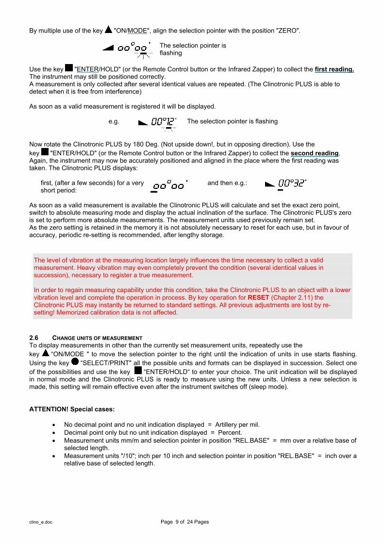
By multiple use of the key "ON/MODE", align the selection pointer with the position "ZERO".
The selection pointer is flashing
Use the key "ENTER/HOLD" (or the Remote Control button or the Infrared Zapper) to collect the first reading. The instrument may still be positioned correctly. A measurement is only collected after several identical values are repeated. (The Clinotronic PLUS is able to detect when it is free from interference) As soon as a valid measurement is registered it will be displayed.
e.g. The selection pointer is flashing
Now rotate the Clinotronic PLUS by 180 Deg. (Not upside down!, but in opposing direction). Use the key "ENTER/HOLD" (or the Remote Control button or the Infrared Zapper) to collect the second reading. Again, the instrument may now be accurately positioned and aligned in the place where the first reading was taken. The Clinotronic PLUS displays:
first, (after a few seconds) for a very short period:
and then e.g.:
As soon as a valid measurement is available the Clinotronic PLUS will calculate and set the exact zero point, switch to absolute measuring mode and display the actual inclination of the surface. The Clinotronic PLUS's zero is set to perform more absolute measurements. The measurement units used previously remain set. As the zero setting is retained in the memory it is not absolutely necessary to reset for each use, but in favour of accuracy, periodic re-setting is recommended, after lengthy storage.
The level of vibration at the measuring location largely influences the time necessary to collect a valid measurement. Heavy vibration may even completely prevent the condition (several identical values in succession), necessary to register a true measurement. In order to regain measuring capability under this condition, take the Clinotronic PLUS to an object with a lower vibration level and complete the operation in process. By key operation for RESET (Chapter 2.11) the Clinotronic PLUS may instantly be returned to standard settings. All previous adjustments are lost by re-setting! Memorized calibration data is not affected.
2.6 CHANGE UNITS OF MEASUREMENT To display measurements in other than the currently set measurement units, repeatedly use the key “ON/MODE " to move the selection pointer to the right until the indication of units in use starts flashing. Using the key “SELECT/PRINT" all the possible units and formats can be displayed in succession. Select one of the possibilities and use the key “ENTER/HOLD“ to enter your choice. The unit indication will be displayed in normal mode and the Clinotronic PLUS is ready to measure using the new units. Unless a new selection is made, this setting will remain effective even after the instrument switches off (sleep mode). ATTENTION! Special cases:
No decimal point and no unit indication displayed = Artillery per mil. Decimal point only but no unit indication displayed = Percent. Measurement units mm/m and selection pointer in position "REL.BASE" = mm over a relative base of
selected length. Measurement units "/10"; inch per 10 inch and selection pointer in position "REL.BASE" = inch over a
relative base of selected length.

clino_e.doc Page 10 of 24 Pages
The following measuring units may be selected:
Display/Format Measuring unit Code Character for printout
00°00’ Degree /Min G 00’00’’ Min / Sec S
00.00 gon Gon / 2 Dec. O .0000 gon Gon / 4 Dec. O
00.00 mm/m mm/rel. base / 2 Dec. L .0000 mm/m mm/rel. base / 4 Dec. L .0000 "/10" Inch/rel. base / 4 Dec. H
0000 Artillery Permille A‰ A (Display without units) 00.00 % %
00.00 mm/m mm/m / 2 Dec. M .0000 "/10" Inch/10 Inch I .0000 "/12" Inch/12 Inch K 00.00 mrad Milliradian / 2 Dec. R 0000 mrad Milliradian R
00.00° Degrees /2 Dec. D .0000° Degrees /4 Dec. D
2.7 CHANGE RELATIVE BASE / SAVE SET-UP A mode, displaying inclination by the height in mm / inch at the end of a straight line with the length previously set, is included in the Clinotronic PLUS. "Measurement with relative base in mm or in inch". Factory default settings for base length are: 1000 mm or 10 inch. To change these base lengths or to see which base lengths are presently set, proceed as follows: Repeatedly using the key "ON/MODE”, align the selection pointer with the indication "REL.BASE". Now use the key “SELECT/PRINT " to display the length presently stored. Repeated use of
“SELECT/PRINT" will in turn display the values stored in the "mm" and in the "inch" memory. With the desired display, (note unit indicated; mm/m for length in mm, "/10" for length in inch) use the key
“ENTER/HOLD " to open the memory for alteration. The selection indicator (flashing) will jump below the first digit. Using the key “ON/MODE this digit can be changed. Each key operation will increase the value by 1. Use the key “SELECT/PRINT " to move the selection indicator to the next digit. Change all digits as desired. The value displayed is the base length in mm or in inch depending on the memory opened, no fractions are possible. Use the key "ENTER/HOLD" to store the new value. The new measuring unit will remain stored until newly changed, even after switching the Clinotronic PLUS off (sleep mode). After this operation the Clinotronic PLUS automatically returns to the previously set measuring mode. Inclinations are displayed in the units last set. If necessary change to different measurement unit. The following possibilities are available for measurements with relative base:
00.00 mm/m Selection indicator on position "REL.BASE" .00 00 "/10" Selection indicator on position "REL.BASE"

clino_e.doc Page 11 of 24 Pages
For relative base measurements the following approach is applicable:
2.8 HOLD - FUNCTION This function is available in all measuring modes. Use the key “ENTER/HOLD" (or the Remote Control button or the Infrared Zapper). While the Clinotronic PLUS waits for a valid measurement (several identical values in succession) the display will show . As it is practically impossible for two successive values to be identical while the instrument is handled, the Clinotronic PLUS may be positioned after the key is depressed. As soon as the condition for a valid measurement is fulfilled, the measuring value is displayed with flashing digits. To read the measurement value, the Clinotronic PLUS may be removed from its located position. The display value is "frozen". Use the key “SELECT/PRINT " to transmit the value via the port RS485 to a connected peripheral instrument. Without a connection, the HOLD mode will be cancelled. The level of vibration at the measuring location considerably influences the time necessary to collect a valid measurement. Severe vibration may even completely prevent the condition (several identical values in succession), necessary to register a true measurement. In order to regain measuring capability under this condition the HOLD mode can be cancelled by pressing
“SELECT/PRINT” 2.9 PRINT - FUNCTION. Using the Key “SELECT/PRINT " will send the displayed value via RS485 to the printer. The possibilities for such a connection are described in the Appendix. 2.10 CANCEL You have started with an alteration, but wish to discontinue. Provided, no parameters have yet been transferred by
“ENTER/HOLD" this is possible. Press the “ON/MODE" key first and keep it pressed while pressing also the key “SELECT/PRINT" to regain the "old" parameters. YOUR SALVATION, IF YOU ENTERED THE CALIBRATION PROGRAMME ACCIDENTALLY!

clino_e.doc Page 12 of 24 Pages
2.11 RESET The Clinotronic PLUS shows: no reaction to key operation. Or the display is incomprehensive. Probably you found a faulty key sequence as yet unknown to us, which the processor cannot interpret. If you wish to return the Clinotronic PLUS to factory default setting. (Cancel all parameters set by operator). Or you have special reasons (problems using hold function or zero setting), which force you to a reset in order to continue operation. Solution: Depress first the key “ON/MODE" and keep it pressed while pressing “ENTER/HOLD" for longer than 10 second. Apart from the calibration data all stored settings are removed or are set to factory defaults. The Clinotronic PLUS is now set as follows:
Measuring mode Absolute Measuring unit mm/m 2 decimals Relative base 100 mm and 10 inch Absolute zero Lost, chapter 2.5 Relative zero Lost, chapter 3.2
2.12 DATA TRANSMISSION True RS485 – Interface / connections to various WYLER instruments such as e.g. LEVELMETER 2000, WYLER T/C as well as to a RS 232 or USB port of a PC (Special cable WYLER required). 3. APPLICATIONS 3.1. ABSOLUTE MEASUREMENT For accurate measurements it is advisable to reset the absolute zero point of the Clinotronic PLUS in accordance with chapter 2.5. prior to first measurement. Thereafter place the Clinotronic PLUS on the surface to be measured, the instrument directly displays the inclination with respect to absolute horizontal or vertical.
Inclined to the right / +08°32‘ Declined to the right / -08°32‘
3.2. RELATIVE MEASUREMENT Place the Clinotronic PLUS on the reference surface and using the key “ON/MODE" select the mode "RELATIVE" the selection indicator will then flash. Using the key “ENTER/HOLD" will put the relative mode into operation, allow a moment until the Clinotronic PLUS displays showing that the reference is set. The Clinotronic PLUS will then display the difference of inclination with respect to the pre-set value. To return to absolute mode use the key “ON/MODE"

clino_e.doc Page 13 of 24 Pages
3.3 MEASUREMENT OF WIDE ANGLES The four surfaces framing the instrument are finished perpendicularly to each other. Each of them may be employed as a measuring base thereby allowing inclination measurements at any angle greater than the sensor measuring capacity. (± 45 Deg) Vertical and horizontal measurements / Measurements with the different bases
Declined to the right Inclined to the right
Inclined to the right Inclined slightly to the right
3.4 SHUT OFF THE INSTRUMENT To shut off the instrument press the “ON/MODE " key for min. 3 seconds until the display is empty.
Remarks: When an external power supply is connected the instrument can not be shut off.
clino_e.doc Page 14 of 24 Pages
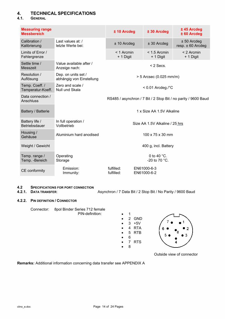
4. TECHNICAL SPECIFICATIONS 4.1. GENERAL
Measuring range Messbereich ± 10 Arcdeg ± 30 Arcdeg ± 45 Arcdeg
± 60 Arcdeg
Calibration / Kalibrierung
Last values at: / letzte Werte bei: ± 10 Arcdeg ± 30 Arcdeg ± 50 Arcdeg
resp. ± 60 Arcdeg
Limits of Error / Fehlergrenze < 1 Arcmin
+ 1 Digit < 1.5 Arcmin
+ 1 Digit < 2 Arcmin
+ 1 Digit
Settle time / Messzeit
Value available after / Anzeige nach: < 2 Secs.
Resolution / Auflösung
Dep. on units set / abhängig von Einstellung > 5 Arcsec (0.025 mm/m)
Temp. Coeff. / Temperatur-Koeff.
Zero and scale / Null und Skala < 0.01 Arcdeg./°C
Data connection / Anschluss RS485 / asynchron / 7 Bit / 2 Stop Bit / no parity / 9600 Baud
Battery / Batterie 1 x Size AA 1.5V Alkaline
Battery life / Betriebsdauer
In full operation / Vollbetrieb Size AA 1.5V Alkaline / 25 hrs
Housing / Gehäuse Aluminium hard anodised 100 x 75 x 30 mm
Weight / Gewicht 400 g, incl. Battery
Temp. range / Temp. -Bereich
Operating Storage
0 to 40 °C. -20 to 70 °C.
CE conformity Emission: Immunity:
fulfilled: EN61000-6-3 fulfilled: EN61000-6-2
4.2 SPECIFICATIONS FOR PORT CONNECTION 4.2.1. DATA TRANSFER: Asynchron / 7 Data Bit / 2 Stop Bit / No Parity / 9600 Baud 4.2.2. PIN DEFINITION / CONNECTOR Connector: 8pol Binder Series 712 female
PIN-definition: 1 2 GND 3 +5V 4 RTA 5 RTB 6 7 RTS 8
Outside view of connector
Remarks: Additional information concerning data transfer see APPENDIX A

clino_e.doc Page 15 of 24 Pages
4.2.3. CONNECTION MODE I) Clinotronic PLUS (Compatibility) – MODE Polling mode
Pressing SELECT/PRINT Key will send response Receiving (ASCII Character ‚H‘) will bring instrument to HOLD-MODE. Receiving (ASCII Character ‚P‘) will send data to port (response)
Timing of data exchange
Immediately after receiving command, response will be sent. During the data transmission (response) the open drain signal (RTS) will be held low
Used data frame Frame characters: (All ASCII - Characters)
II) Clinotronic PLUS -Mode Character set
ASCII Numbers ‚0‘ .. ‚9‘ ASCII Letters ‚A‘ .. ‚F‘ ASCII Special characters ‚~‘ ASCII Control characters <CR>
Polling mode
Instrument will not transmit any data spontaneously Instrument will transmit a response only upon reception of a command The same data frame structure is used for commands as well as responses
Timing of data exchange
A request may be sent to the instrument with max. rate or with shorter as well as larger intervals between the individual characters.
Immediately after receiving (<CR>, = carriage return) of command, response will be sent. During the data transmission (response) the open drain signal (RTS) will be held low

clino_e.doc Page 16 of 24 Pages
Command / Response data frame structure
Header ASCII ‚~‘ (Begin of command or response) ASCII ‚~‘ (minimum 4 of these characters must be sent) ASCII ‚~‘ ASCII ‚~‘
Address ASCII ‚0‘ .. ‚9‘ ‚A‘ .. ‚F‘ Bit[7..4] + (Instruments resp. sensor address) ASCII ‚0‘ .. ‚9‘ ‚A‘ .. ‚F‘ Bit[3..0] + ASCII ‚1‘
Opcode ASCII ‚0‘ .. ‚9‘ ‚A‘ .. ‚F‘ Bit[3..0] +
Data ASCII ‚0‘ .. ‚9‘ ‚A‘ .. ‚F‘ Bit[31..28] + ASCII ‚0‘ .. ‚9‘ ‚A‘ .. ‚F‘ Bit[27..24] + ASCII ‚0‘ .. ‚9‘ ‚A‘ .. ‚F‘ Bit[23..20] + ASCII ‚0‘ .. ‚9‘ ‚A‘ .. ‚F‘ Bit[19..16] + ASCII ‚0‘ .. ‚9‘ ‚A‘ .. ‚F‘ Bit[15..12] + ASCII ‚0‘ .. ‚9‘ ‚A‘ .. ‚F‘ Bit[11..8] + ASCII ‚0‘ .. ‚9‘ ‚A‘ .. ‚F‘ Bit[7..4] + ASCII ‚0‘ .. ‚9‘ ‚A‘ .. ‚F‘ Bit[3..0] +
CheckSum ASCII ‚0‘ .. ‚9‘ ‚A‘ .. ‚F‘ Bit[7..4] ASCII ‚0‘ .. ‚9‘ ‚A‘ .. ‚F‘ Bit[3..0]
Trailer ASCII <CR> (End of command or response) Examples to Clinotronic PLUS -Mode
clino_e.doc Page 17 of 24 Pages
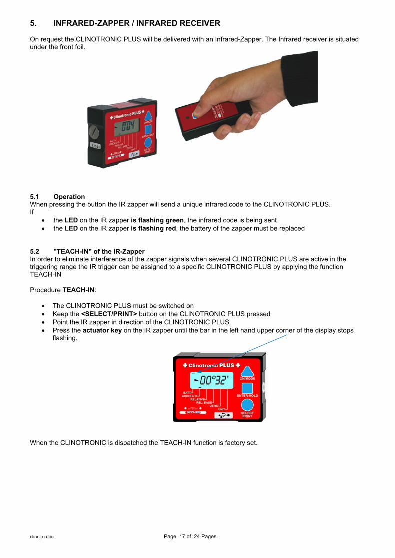
5. INFRARED-ZAPPER / INFRARED RECEIVER On request the CLINOTRONIC PLUS will be delivered with an Infrared-Zapper. The Infrared receiver is situated under the front foil.
5.1 Operation When pressing the button the IR zapper will send a unique infrared code to the CLINOTRONIC PLUS. If
the LED on the IR zapper is flashing green, the infrared code is being sent the LED on the IR zapper is flashing red, the battery of the zapper must be replaced
5.2 "TEACH-IN" of the IR-Zapper In order to eliminate interference of the zapper signals when several CLINOTRONIC PLUS are active in the triggering range the IR trigger can be assigned to a specific CLINOTRONIC PLUS by applying the function TEACH-IN Procedure TEACH-IN:
The CLINOTRONIC PLUS must be switched on Keep the <SELECT/PRINT> button on the CLINOTRONIC PLUS pressed Point the IR zapper in direction of the CLINOTRONIC PLUS Press the actuator key on the IR zapper until the bar in the left hand upper corner of the display stops
flashing.
When the CLINOTRONIC is dispatched the TEACH-IN function is factory set.

clino_e.doc Page 18 of 24 Pages
6. SERVICE 6.1 CALIBRATION A reserved memory space incorporated in the Clinotronic PLUS contains calibration data in predefined intervals. Prior to all displays this data is accessed applying a specialized interpolation and is used to compute the measurement value. Calibration data stored in this memory is initiated from an automatic calibration process based on a high accuracy dividing head, which is performed at the manufacturing stage. Recalibration is possible at any time if suitable and accurate equipment which allows precise setting of angles (dividing head, sine equipment etc.) is available. A recalibration may also be performed at any time starting the calibration program by key operation. The following example is for a Clinotronic PLUS with a measuring range of ± 45 deg. Basically the same procedure is used for other ranges. **1** Mount the Clinotronic PLUS to the angular reference equipment and set an angle of 50 deg. sloping to
the right (display facing you and data connector being on the right side). Connect the cable of the remote push button to the data connector. If an IR zapper is available, the calibration procedure can also be controlled using the zapper.
**2** Before starting the calibration procedure preferably a reset is performed (See chapter 2.11) To reset, simultaneously press the two keys “ON/MODE" and “ENTER/HOLD" by starting with the “ON/MODE" key, for a min. period of 1 sec. Start the calibration program by pressing first the key “SELECT/PRINT” and keep pressed while using simultaneously the key “ENTER/HOLD” for a period of min. 5 seconds. A successful start to the calibration program is indicated by the display showing at first " 00.00" thereafter displaying
in flashing mode which represents the first calibration point.
**3** To enter a calibration point, first confirm that the reference setting corresponds with the value displayed, then press the remote button or with the IR zapper, or if both are not available with the key “ENTER/HOLD”. Allow a moment (a few seconds) for the Clinotronic PLUS to register the respective data. The instrument must remain untouched.
**4** When the calibration data for one setting is successfully stored, the Clinotronic PLUS will display the next setting required. The display will, in 5 deg. steps successively show to
Due to automatic adjustment of acceptance requirement calibration may be impossible if vibrations are present or if an unstable set-up is used. **5**
Adjust the angular equipment according to the new value flashing on the Clinotronic PLUS display.
**6** Repeat operation 3 to 5 until the last value is registered.
**7** Upon completion the Clinotronic PLUS automatically returns to the mode last set or, if the setting data was cancelled to the standard setting. IMPORTANT! Prior to absolute measurements it is necessary to reset zero.

clino_e.doc Page 19 of 24 Pages
6.2 ACCESSORIES / SPARE PARTS The following items are available:
Batteries 1 x Size AA 1.5V Alkaline or 1 x Size AA 3.0V MnO2-Lithium
P/N 604-012-0001
604-012-0002
Serial cable RS232 conversion to RS485 P/N 015-025-928-232
Interface-Connector Clinotronic PLUS to PC (RS232)
With this connector the Clinotronic PLUS may be connected to the com port (RS232) of a PC. The cable mentioned below is needed in addition.
P/N 065-STECKER-232
Cable 2.5m connecting Clinotronic PLUS to Interface connector
With this cable and the above mentioned connector the Clinotronic PLUS may be connected to the com port (RS232) of a PC
P/N 065-025-878-001
Cable 1.8m connecting Clinotronic PLUS to a USB-port
With this cable the CLINOTRONIC PLUS can be connected to a USB port of a PC
P/N 015-018-468-USB
Cable 2.5m with remote button
The cable is recommended for calibration procedure or for applying the HOLD function without touching the instrument.
P/N 015-025-8D1PLUS
Infrared-Zapper For initiating the measuring process in the calibration procedure or for initiating the HOLD function without touching the instrument.
P/N 015-005-005
Various measuring bases
Flat or prismatic in length of : 100 mm to 300 mm
Various threads and magnetic inserts
See Appendix B
7. STORAGE 7.1 STORAGE POSITION INSTRUMENT For long periods of storage never place the Clinotronic PLUS in a position with it's longitudinal axis vertical. An incorrect storage position may, due to overloading of the pendulum system, result in a substantial drift of the zero point whilst recovering its equilibrium.
7.2 CARE AND HANDLING OF THE BATTERIES Read the instructions in your manual before installing batteries. Make sure to insert the batteries properly, following the symbols showing you the correct way to position the positive (+) and negative (-) ends of the batteries. Keep battery contact surfaces clean by gently rubbing with a clean pencil eraser or cloth. Replace batteries with the size and type specified by the device's manufacturer. Remove all used batteries from the device at the same time, and then replace them with new batteries of the same size and type. Store batteries in a cool, dry place at normal room temperature. Remove batteries from devices that will be stored for extended periods. Don't dispose of batteries in a fire—they may rupture or leak. Don't recharge a battery unless it is specifically marked "rechargeable." Attempting to recharge a normal battery could result in rupture or leakage.

clino_e.doc Page 20 of 24 Pages
APPENDIX A a) Connecting a remote button to the Clinotronic PLUS using the RS485 interface
b) Connecting the Clinotronic PLUS to a computer with a RS485 interface using the RS485 interface of the
instrument
c) Connecting the Clinotronic PLUS to a computer with a RS485 interface using the RS485 interface of the
instrument / also a remote button installed

clino_e.doc Page 21 of 24 Pages
d) Connecting the Clinotronic PLUS to a computer with a RS232 interface using the RS485 interface of the instrument
Remarks: Cable and interface connector can be ordered from the nearest distributor or from WYLER AG. e) Connecting the Clinotronic PLUS to a computer with a RS232 interface using the RS485 interface of the
instrument / also a remote button installed
f) Connecting the Clinotronic PLUS to a computer with a RS422 interface using the RS485 interface of the
instrument
clino_e.doc Page 22 of 24 Pages
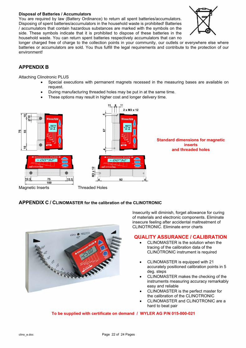
Disposal of Batteries / Accumulators You are required by law (Battery Ordinance) to return all spent batteries/accumulators. Disposing of spent batteries/accumulators in the household waste is prohibited! Batteries / accumulators that contain hazardous substances are marked with the symbols on the side. These symbols indicate that it is prohibited to dispose of these batteries in the household waste. You can return spent batteries respectively accumulators that can no longer charged free of charge to the collection points in your community, our outlets or everywhere else where batteries or accumulators are sold. You thus fulfill the legal requirements and contribute to the protection of our environment! APPENDIX B Attaching Clinotronic PLUS
Special executions with permanent magnets recessed in the measuring bases are available on request.
During manufacturing threaded holes may be put in at the same time. These options may result in higher cost and longer delivery time.
Standard dimensions for magnetic inserts
and threaded holes
Magnetic Inserts Threaded Holes
APPENDIX C / CLINOMASTER for the calibration of the CLINOTRONIC
Insecurity will diminish, forget allowance for curing of materials and electronic components. Eliminate insecure feeling after accidental maltreatment of CLINOTRONIC. Eliminate error charts QUALITY ASSURANCE / CALIBRATION
CLINOMASTER is the solution when the tracing of the calibration data of the CLINOTRONIC instrument is required
CLINOMASTER is equipped with 21
accurately positioned calibration points in 5 deg. steps
CLINOMASTER makes the checking of the instruments measuring accuracy remarkably easy and reliable
CLINOMASTER is the perfect master for the calibration of the CLINOTRONIC
CLINOMASTER and CLINOTRONIC are a hard to beat pair
To be supplied with certificate on demand / WYLER AG P/N 015-000-021
clino_e.doc Page 23 of 24 Pages
APPENDIX D Repair of Measuring Instruments Normally any instruments requiring repair can be sent to the local WYLER partner (local distributor) who will take the necessary steps and make the arrangements for repair on behalf of the customer. Express Repair Service, ERS A large number of customers can not miss the instruments for a longer period as these are in daily operation. For these cases WYLER SWITZERLAND has created a new service called "Express Repair Service, ERS". Employing this service the transport time from the user to WYLER SWITZERLAND and back and thus the complete repair time can be reduced considerably. A simplified description of this service:
The customer announces the repair request to the local WYLER partner in his country. The WYLER partner will inform the customer about the possibility of the ERS service outlining the
advantages and consequences of this service, such as e.g. o reduced total repair time o required acceptance to repair without quote up to 65 % of the price for a new instrument o suitable packing for air transport o expenses of the ERS
In case the customer decides to use the ERS, the customer informs the local WYLER partner or directly WYLER SWITZERLAND providing the necessary data.
The customer will receive all information and instructions necessary for a smooth handling, the customer has just to pack the product suitably and to fill in a form for the TNT courier service as well as to announce the readiness to the local TNT office for pick-up. Everything else will run automatically.
Products reaching WYLER SWITZERLAND under this service will be handled with first priority, and the instrument will be returned using the same carrier.
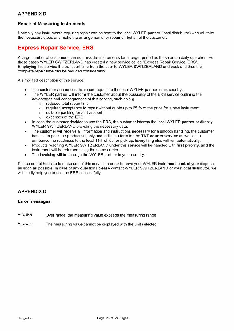
The invoicing will be through the WYLER partner in your country. Please do not hesitate to make use of this service in order to have your WYLER instrument back at your disposal as soon as possible. In case of any questions please contact WYLER SWITZERLAND or your local distributor, we will gladly help you to use the ERS successfully. APPENDIX D Error messages
Over range, the measuring value exceeds the measuring range
The measuring value cannot be displayed with the unit selected

clino_e.doc Page 24 of 24 Pages
WYLER AG Im Hölderli CH-8405 WINTERTHUR Switzerland
Tel. 0041 (0) 52 233 66 66 Fax. 0041 (0) 52 233 20 53
Homepage: http://www.wylerag.com E-Mail: [email protected]