OPERATOR™S MANUAL 300W 060110 1 1. INTRODUCTION 1.1 SCOPE OF MANUAL This Operator’s Manual...
16
IMPORTANT NOTES: 1) The contents of this manual are protected by copyright. Reproduction of any part can be made only with the specific written permission of Kepco, Inc. 2) Data subject to change without notice. KEPCOfi THE POWER SUPPLIER™ MODEL OPERATORS MANUAL KEPCO INC. KEPCO, INC. ! 131-38 SANFORD AVENUE ! FLUSHING, NY. 11355 U.S.A. ! TEL (718) 461-7000 ! FAX (718) 767-1102 email: [email protected] ! World Wide Web: http://www.kepcopower.com An ISO 9001 Company. '2010, KEPCO, INC P/N 228-1498-R5 RKW 300W SERIES POWER SUPPLY SINGLE OUTPUT, UNIVERSAL INPUT SINGLE PHASE, 0.99 POWER FACTOR RKW 300W SERIES POWER SUPPLY MODELS RKW 3.3-70K, RKW 5-60K, RKW 12-27K, RKW 15-22K, RKW 24-14K, RKW 28-12K, RKW 48-7K
Transcript of OPERATOR™S MANUAL 300W 060110 1 1. INTRODUCTION 1.1 SCOPE OF MANUAL This Operator’s Manual...

IMPORTANT NOTES:
1) The contents of this manual are protected by copyright. Reproduction of any part can bemade only with the specific written permission of Kepco, Inc.
2) Data subject to change without notice.
KEPCO® THE POWER SUPPLIER�
MODEL
OPERATOR�S MANUAL
KEPCO INC.
KEPCO, INC. ! 131-38 SANFORD AVENUE ! FLUSHING, NY. 11355 U.S.A. ! TEL (718) 461-7000 ! FAX (718) 767-1102email: [email protected] ! World Wide Web: http://www.kepcopower.com
An ISO 9001 Company.
©2010, KEPCO, INCP/N 228-1498-R5
RKW 300W SERIESPOWER SUPPLY
SINGLE OUTPUT, UNIVERSAL INPUTSINGLE PHASE, 0.99 POWER FACTOR
RKW 300W SERIES POWER SUPPLY MODELS
RKW 3.3-70K, RKW 5-60K, RKW 12-27K, RKW 15-22K, RKW 24-14K, RKW 28-12K, RKW 48-7K
i RKW 300W 060110
TABLE OF CONTENTS
SECTION PAGE
1. Introduction........................................................................................................................................................ 11.1 Scope of Manual............................................................................................................................................. 11.2 Description...................................................................................................................................................... 12. Specifications .................................................................................................................................................... 13. Operation........................................................................................................................................................... 53.1 Voltage Adjustment ........................................................................................................................................ 63.2 Remote Voltage Control ................................................................................................................................. 73.3 Remote Turn On-Turn Off............................................................................................................................... 74. Alarm Functions................................................................................................................................................. 84.1 Overvoltage and Overtemperature Protection................................................................................................ 84.2 Overcurrent Protection ................................................................................................................................... 84.3 Fan Failure ..................................................................................................................................................... 84.4 Optical Coupler Output Alarm Circuit.............................................................................................................. 84.5 Undervoltage .................................................................................................................................................. 95. Load Connection ............................................................................................................................................... 95.1 Connecting the Load Using Local Sensing.................................................................................................... 95.2 Connecting the Load Using Remote Sensing................................................................................................. 95.3 Parallel Connection ........................................................................................................................................ 95.3.1 Current Balancing ...................................................................................................................................... 105.3.2 Master-Slave Configurations ..................................................................................................................... 115.3.2.1 Master-Slave, Multiple Loads.................................................................................................................. 115.3.2.2 Master-Slave, Single Load...................................................................................................................... 115.4 Series Connection ........................................................................................................................................ 115.5 Preliminary Electrical Check......................................................................................................................... 126. Fan Maintenance............................................................................................................................................. 12
LIST OF FIGURES
FIGURE TITLE PAGE
1 Mechanical Outline Drawing of the RKW 300W Power Supply.................................................................. 42 Power Rating vs. Temperature................................................................................................................... 53 Mounting Positions for the RKW 300W Power Supply............................................................................... 54 Locations of Operating Controls, Indicators and Terminals ....................................................................... 65 Connections for Remote Voltage Control................................................................................................... 76 Output Alarm Circuit, Optically Isolated...................................................................................................... 87 RKW 300W Power Failure Timing Diagram ............................................................................................... 98 Correct and incorrect Methods of Load Connection................................................................................. 109 Parallel Connection with Current Balancing ............................................................................................. 1010 Parallel Connection, Master-Slave, Multiple Loads.................................................................................. 1111 Parallel Connection, Master-Slave, Single Load ...................................................................................... 1112 Series Connection .................................................................................................................................... 1213 Functional Checkout................................................................................................................................. 12
LIST OF TABLES
TABLE TITLE PAGE
1 Output Ratings and Specifications ............................................................................................................. 12 Power Supply Ratings and Specifications .................................................................................................. 23 Function of Controls, Indicators and Terminals .......................................................................................... 6

RKW 300W 060110 1
1. INTRODUCTION
1.1 SCOPE OF MANUALThis Operator's Manual covers the installation and operation of the Kepco RKW 300W Series ofPFC (Power Factor Corrected), RoHS (Reduction of Hazardous Substances) compliant, switchingpower supplies. For service information, write directly to: Kepco Inc., 131-38 Sanford Avenue,Flushing, New York, 11355, U.S.A. Please state Model Designation and Serial Number of yourRKW Power Supply. This information can be found on the nameplate of the unit.
1.2 DESCRIPTIONThe Kepco RKW 300W Series consists of seven models of switching power supplies, each with asingle output as shown in Table 1. Units may be operated with a nominal 100V a-c to 240V a-c(input voltage range 85 to 265 Va-c), 50-60 Hz (input frequency range 47-66Hz). They will alsooperate on 110V to 370V d-c input. The RKW 300W Series employs a light weight ferrite core with200 KHz switching frequency. Regulation is provided by pulse width modulation. A power stagewith a MOSFET on each side of the primary winding, operating in the forward mode provides asmooth isolated d-c output. A thyristor circuit prevents excessive turn-on current surge. Overvolt-age, overtemperature, fan failure and power failure protections and an isolated remote TTL ON-OFF control are provided. An LED �output voltage ON� light and an output voltage adjust trimmerare visible near the output terminals (upper right side of the front panel). Units are manufacturedon a steel frame with a steel cover.
2. SPECIFICATIONSTable 1 contains specifications and operating limits of individual RKW 300W Series models. Table2 contains specifications and operating limits common to all RKW 300W Series Models. Thesespecifications are at nominal input voltages at 25°C unless otherwise specified.
TABLE 1. OUTPUT RATINGS AND SPECIFICATIONSMODEL RKW 300W 3.3-70K 5-60K 12-27K 15-22K 24-14K 28-12K 48-7K
Output Volts d-c 3.3V 5V 12V 15V 24V 28V 48V
Adjustment Range 1.8-3.6 3.5-6.0 7.2-14.4 10.5-18.0 16.8-28.8 19.6-33.6 33.6-52.8Voltage Setting 3.3 ±0.03 5 ±0.05 12 ±0.12 15 ±0.15 24 ±0.24 28 ±0.28 48 ±0.48
�10°C to 40°C
Amps 70 60 27 22 14 12 7Watts 231 300 324 330 336 336 336
Maximum Output Ratings (A,W)
50°Camb
Amps 61.6 60 27 22 14 12 7Watts 203.3 300 324 330 336 336 336
56°Camb
Amps 56 52.8 23.8 19.4 12.3 10.6 6.2Watts 184.8 264 285.1 290.4 295.7 295.7 295.7
60°C,amb
Amps 52.6 48 21.6 17.6 11.2 9.6 5.6Watts 173.7 240 259.2 264 268.8 268.8 268.8
65°C,amb
Amps 49 42 18.9 15.4 9.8 8.4 4.9Watts 161.7 210 226.8 231 235.2 235.2 235.2
Overcurrent Setting (Amps)(1) 73.5 - 91 63 - 78 28.4 - 35.1 23.1 - 28.6 14.7 - 18.2 12.6 - 15.6 7.4 - 9.1Current Short Circuit 90 82 35 29 20 17 11OVP Setting (Volts)(2) 4.0 - 4.6 6.2 - 7.0 14.8 - 16.8 18.6 - 21.0 29.8 - 33.6 34.7 - 39.2 55.0 - 59.9Efficiency % typical
AC Input 100V 68 74 76 77 80 80 81AC Input 200V 72 78 80 81 84 84 85
Ripple & Noise(3) (mV, p-p)
ripple 80 80 120 120 150 150 200
ripple noise 120 120 150 150 200 200 300
(1) Square type. If overcurrent condition continues beyond 30 seconds, the output is shut OFF. Recovery is by removing power and reapplying power after about 40 seconds or by opening and reclosing the RC terminals .
(2) When overvoltage is detected, output is shut OFF. Recovery is by removing power and reapplying power after about 40 seconds or by opening and reclosing the RC terminals (no delay).
(3) Ripple and noise specifications are 1.5 times indicated values for temperature range of -10 to 0°C. Ripple and noise levels above are satisfied when conditions are 0 to 100% load, 0 to 65°C (derated from 50 to 65°C per Figure 2, der-ated from 40 to 65°C for 3.3V model), and bandwidth ≤ 100MHz.
2 RKW 300W 060110
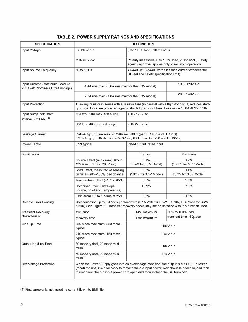
TABLE 2. POWER SUPPLY RATINGS AND SPECIFICATIONSSPECIFICATION DESCRIPTION
Input Voltage 85-265V a-c (0 to 100% load, -10 to 65°C)
110-370V d-c Polarity insensitive (0 to 100% load, -10 to 65°C) Safety agency approval applies only to a-c input operation.
Input Source Frequency 50 to 60 Hz 47-440 Hz. (At 440 Hz the leakage current exceeds the UL leakage safety specification limit).
Input Current: (Maximum Load At 25°C with Nominal Output Voltage) 4.4A rms max. (3.6A rms max for the 3.3V model) 100 - 120V a-c
2.2A rms max. (1.8A rms max for the 3.3V model) 200 - 240V a-c
Input Protection A limiting resistor in series with a resistor fuse (in parallel with a thyristor circuit) reduces start-up surge. Units are protected against shorts by an input fuse. Fuse value 10.0A At 250 Volts
Input Surge cold start, interval > 30 sec (1)
15A typ., 20A max. first surge 100 - 120V ac
30A typ., 40 max. first surge 200- 240 V ac
Leakage Current: 024mA typ., 0.3mA max. at 120V a-c, 60Hz (per IEC 950 and UL1950)0.31mA typ., 0.38mA max. at 240V a-c, 60Hz (per IEC 950 and UL1950)
Power Factor 0.99 typical rated output, rated input
Stabilization Typical Maximum
Source Effect (min - max) (85 to 132 V a-c, 170 to 265V a-c)
0.1% (5 mV for 3.3V Model)
0.2% (10 mV for 3.3V Model)
Load Effect, measured at sensing terminals (0%-100% load change)
0.2% (10mV for 3.3V Model)
0.4% 20mV for 3.3V Model)
Temperature Effect (�10° to 65°C) 0.5% 1.0%
Combined Effect (envelope, Source, Load and Temperature)
±0.9% ±1.8%
Drift (from 1/2 to 8 hours at 25°C) 0.2% 0.5%
Remote Error Sensing: Compensation up to 0.4 Volts per load wire (0.15 Volts for RKW 3.3-70K, 0.25 Volts for RKW 5-60K) (see Figure 8). Transient recovery specs may not be satisfied with this function used.
Transient Recoverycharacteristic
excursion ±4% maximum 50% to 100% load, transient time >50µsecrecovery time 1 ms maximum
Start-up Time 350 msec maximum, 280 msec typical. 100V a-c
210 msec maximum, 150 msec typical.
240V a-c
Output Hold-up Time 30 msec typical, 20 msec mini-mum. 100V a-c
40 msec typical, 20 msec mini-mum.
240V a-c
Overvoltage Protection When the Power Supply goes into an overvoltage condition, the output is cut OFF. To restart (reset) the unit, it is necessary to remove the a-c input power, wait about 40 seconds, and then to reconnect the a-c input power or to open and then reclose the RC terminals.
(1) First surge only, not including current flow into EMI filter

RKW 300W 060110 3
Remote Control ON/OFF: "High", 2.4V to 24V (or open), unit OFF- Fan Off ; "Low", 0.0V to 0.4V (or closed), unit ON.Source current is 1.6mA maximum at low level, and sink current is 1.0 mA maximum at high level. The ±RC terminals are isolated from the a-c input terminal and the DC output terminals. When remote ON/OFF is not in use, ±RC terminals must be shorted (use shorting link sup-plied) for unit to operate.
Operating Temperature: -10 to 65°C (see figures 2 and 3)
Startup Temperature -20 to -10°C (see Figure 2)
Storage Temperature: -30°C to +75°C
Withstanding voltage : (at 15-35°C ambient, 10-85% relative humidity)
2000Va-c for 1 minute. Cutout current is 20mA Between input and ground
500Va-c for 1 minute. Cutout current is 100mA Between output and ground
3000Va-c for 1 minute. Cutout current is 20mA Between input and output
Insulation Resistance: (at 15-35°C ambient, 10-85% relative humidity)
Between output and ground, input and ground, and input and output, 100 Megohms minimum (500Vdc)
Humidity: 10% to 95% relative humidity, noncondensing, Wet Bulb tem-perature</=35°C
operating and non-operating
Vibration: 5-10 Hz., 10mm amplitude, 10-200 Hz., acceleration 64.3ft./s2 ( 19.6m/s2) (2g)
non-operating, 1 hr. on each of 3 axes, sweep time 10 minutes
Shock: (non-operating, 1/2 sine pulse, three shocks on each axis, Power Supply is fixed on its bottom side)
Acceleration: 964.6ft./s2 (294m/s2 ) (30g), Pulse Duration: 11ms ± 5 msec
Safety: All units designed to meet UL1950, CSA Electrical Bulletin 22.2 No.950-95 (certified by UL), and TÜV Rheinland EN60950 (ambient temp.50°C max., 3.3V Model: 40°C max). Meets Creepage and Clearance requirements of Dentori, Appendix 8. RKW 300W units are CE marked per the Low Voltage Directive (LVD), 73/23/EEC and 93/68/EEC. [The standards do not apply with DC input operation.]
EMI Conducted: Designed to meet FCC Class B, VCCI-Class B, EN55011-B, EN55022-B.
EMI Radiated: Designed to meet FCC Class B, VCCI-Class B, EN55011-B, EN55022-B.
Input current harmonics: Designed to meet EN61000-3-2.
Immunity: EN61000-6-2:1999
ESD immunity: Designed to meet EN61000-4-2, level 4. normal operation
Fast transient burst immunity: Designed to meet EN61000-4-4 level 3. normal operation
Surge immunity: Designed to meet EN61000-4-5, level 4. no damage
Power frequency magnetic field immunity:
Designed to meet EN61000-4-8, level 4. normal operation
Radiated field immunity: Designed to meet EN61000-4-3 level 3. normal operation
Conducted noise immunity: Designed to meet EN61000-4-6 level 3. normal operation
Voltage dips interruptions and variations:
Designed to meet EN61000-4-11. normal operation
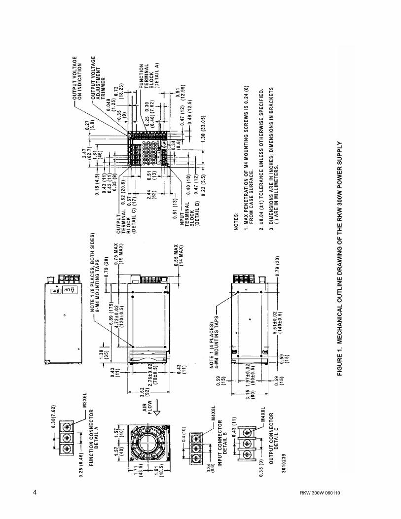
Dimensions: 3.62 in. (92 mm) x 3.15 in. (80 mm) x 6.89 in. (175 mm)
Mounting: Four No. M4 tapped holes on the sides and the bottom
Maximum Screw Penetration: 0.24 in. (6 mm)
Cooling: Forced air flow - one fan
Frame Material/Cover Material: Steel
Weight 3.3 lbs. (1.5Kg) typ., 3.97 lbs.(1.8 Kg) maximum
TABLE 2. POWER SUPPLY RATINGS AND SPECIFICATIONS (CONTINUED)SPECIFICATION DESCRIPTION
4 RKW 300W 060110
FIG
UR
E 1.
MEC
HA
NIC
AL
OU
TLIN
E D
RA
WIN
G O
F TH
E R
KW
300
W P
OW
ER S
UPP
LY

RKW 300W 060110 5
FIGURE 2. POWER RATING VS. TEMPERATURE
FIGURE 3. MOUNTING POSITIONS FOR THE RKW 300W POWER SUPPLY
3. OPERATIONFigure 4 shows the location of all operating controls and input/output terminals followed by anexplanation of each. The unit is shipped with shorting links installed connecting the following ter-minals: +RC to �RC and REF to RV; and sensing cables connecting +DC Output with +S and �DC Output with �S for local sensing.
NOTES:a. +S and �S MUST be properly connected for the unit to operate. For local sens-
ing, leave local sensing cables in place (refer to PAR. 5.1). For remote sensing(at the load), refer to PAR. 5.2.
b. If remote ON/OFF is not being used, ±RC terminals must be connected (useshorting link supplied) for unit to operate.
The power supply will startup from -20 to -10 °C but may not meet the specifications
Maintain a 1.25 in. (30 mm) min. distance between ventilation holes, fan surfaceand surrounding equipment and install to provide heat-outside air exchange

6 RKW 300W 060110
FIGURE 4. LOCATIONS OF OPERATING CONTROLS, INDICATORS AND TERMINALS
3.1 VOLTAGE ADJUSTMENT
Output voltage can be manually adjusted with the voltage adjustment control, Vadj (see Figure 4).To adjust voltage, first place the unit under an operating load, then monitor the (+)S and (�)S
TABLE 3. FUNCTION OF CONTROLS, INDICATORS AND TERMINALS
FIG. 4INDEX
NO.
CONTROL, INDICATOR, TERMINAL FUNCTION
1 A-C Input (L, N) Connect to AC: 100 to 240V input line.
2 Frame Ground (earth) Connect to earth ground. This terminal is connected to the case.
3 DC Output (+, �) Connect to load (see Figure 8).
4 Sense (+S, �S) Used to compensate for voltage drop in the connecting lines from the output terminal to a load; they are connected to ± DC Output terminals for local sensing (see Figure 8).
5 Output Voltage Reference (REF) Using REF terminal (together with the RV terminal) allows all the output voltages of slave power supplies to be controlled by one voltage adjustment of a master power supply (normally connected to the RV terminal with a metal shorting link).
6 Remote Voltage Adjust (RV) This terminal (together with the REF terminal) is used for remotely controlling output voltage (see PAR. 3.2).
7 Current Balance (CB) This terminal is used when several power supplies are connected in parallel (see PAR. 5.3).
8 Power Failure (+PF, -PF) These terminals output an open logic signal if output voltage drops to 80 % or lower of a set voltage, or if output voltage is shut down due to overvoltage or overcurrent pro-tection, fan speed failure, or overheating. (see Figures 6 and 7 ).
9 Remote ON-OFF (+RC, �RC) Output is turned ON-OFF by shorting-opening the RC terminals (output OFF when open). RC terminals are isolated from input and output terminals. Normally, ±RC ter-minals are shorted with a metal shorting link (see PAR. 3.3).
10 Output Voltage Trim Adjust (Vadj) Adjusts output voltage.
11 Output Voltage On indicator (green)
Green LED lights when output voltage is present.
12 Local Sensing Cable Kit Connects ± DC Output to ±S for local sensing (see Figure 8).
NOTE Unit is shipped with shorting links (notshown) connecting +RC to �RC (see PAR. 3.3)and REF to RV (see PAR. 3.2) and with localsensing cables installed (connects +DC Output to+S and �DC Output to �S) (see PAR. 5.2)
RKW 300W 060110 7
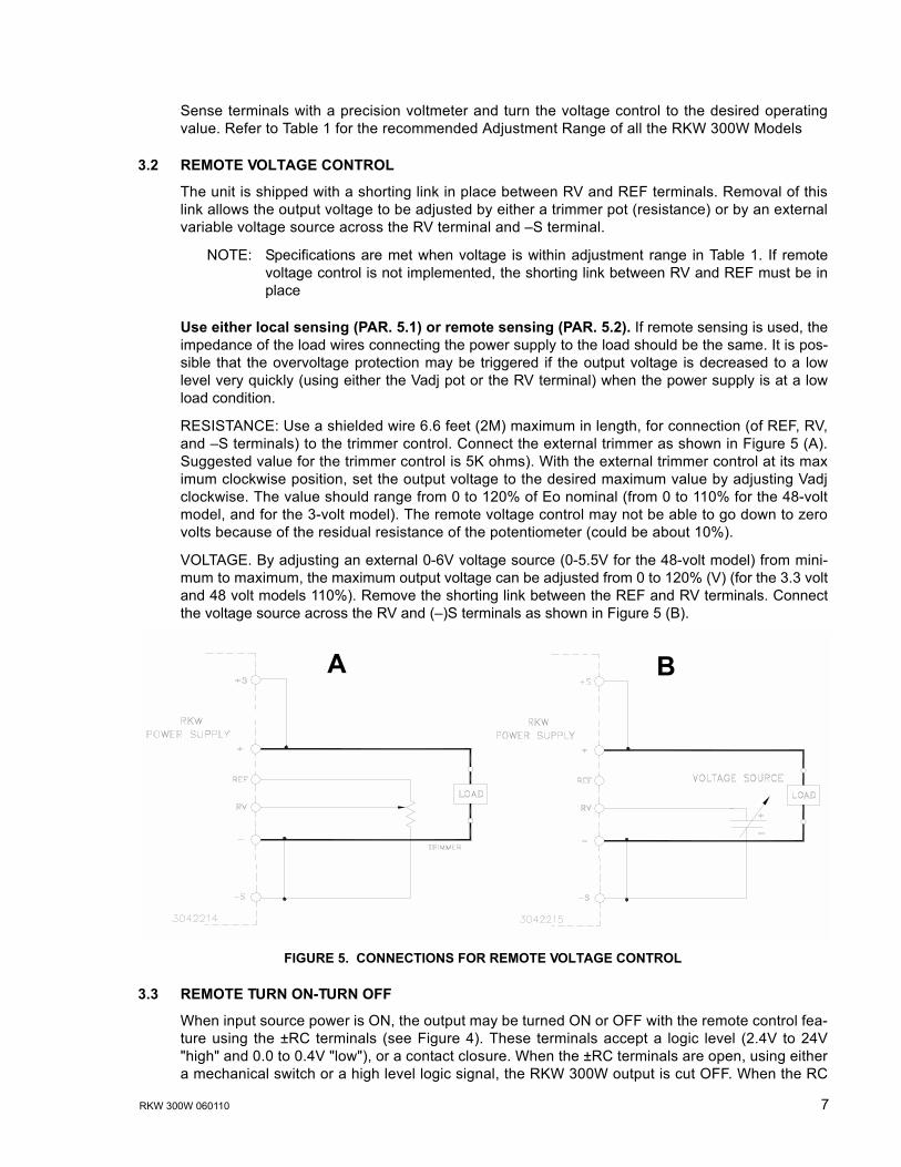
Sense terminals with a precision voltmeter and turn the voltage control to the desired operatingvalue. Refer to Table 1 for the recommended Adjustment Range of all the RKW 300W Models
3.2 REMOTE VOLTAGE CONTROL
The unit is shipped with a shorting link in place between RV and REF terminals. Removal of thislink allows the output voltage to be adjusted by either a trimmer pot (resistance) or by an externalvariable voltage source across the RV terminal and �S terminal.
NOTE: Specifications are met when voltage is within adjustment range in Table 1. If remotevoltage control is not implemented, the shorting link between RV and REF must be inplace
Use either local sensing (PAR. 5.1) or remote sensing (PAR. 5.2). If remote sensing is used, theimpedance of the load wires connecting the power supply to the load should be the same. It is pos-sible that the overvoltage protection may be triggered if the output voltage is decreased to a lowlevel very quickly (using either the Vadj pot or the RV terminal) when the power supply is at a lowload condition.
RESISTANCE: Use a shielded wire 6.6 feet (2M) maximum in length, for connection (of REF, RV,and �S terminals) to the trimmer control. Connect the external trimmer as shown in Figure 5 (A).Suggested value for the trimmer control is 5K ohms). With the external trimmer control at its maximum clockwise position, set the output voltage to the desired maximum value by adjusting Vadjclockwise. The value should range from 0 to 120% of Eo nominal (from 0 to 110% for the 48-voltmodel, and for the 3-volt model). The remote voltage control may not be able to go down to zerovolts because of the residual resistance of the potentiometer (could be about 10%).
VOLTAGE. By adjusting an external 0-6V voltage source (0-5.5V for the 48-volt model) from mini-mum to maximum, the maximum output voltage can be adjusted from 0 to 120% (V) (for the 3.3 voltand 48 volt models 110%). Remove the shorting link between the REF and RV terminals. Connectthe voltage source across the RV and (�)S terminals as shown in Figure 5 (B).
FIGURE 5. CONNECTIONS FOR REMOTE VOLTAGE CONTROL
3.3 REMOTE TURN ON-TURN OFF
When input source power is ON, the output may be turned ON or OFF with the remote control fea-ture using the ±RC terminals (see Figure 4). These terminals accept a logic level (2.4V to 24V"high" and 0.0 to 0.4V "low"), or a contact closure. When the ±RC terminals are open, using eithera mechanical switch or a high level logic signal, the RKW 300W output is cut OFF. When the RC
BA

8 RKW 300W 060110
terminals are shorted, the output returns to within specifications. At low level logic, the maximumsource current is 1.6mA and at high level the sink current is 1.0mA. The RC terminals mustremain shorted if remote ON-OFF is not used. The RC terminals are isolated from both the ACinput and DC output terminals.
4. ALARM FUNCTIONS
4.1 OVERVOLTAGE AND OVERTEMPERATURE PROTECTION
When the output voltage of the RKW 300W Power Supply increases beyond the specified values(see Table 1), the output is cut OFF and the fan turns OFF. To restart (reset) the unit, remove ACinput power, wait about 40 seconds, then reconnect AC input power; or open and then reclose theRC terminals.
When the internal temperature of the RKW 300W Power Supply increases beyond the specifiedvalues (see Table 1), the output is cut OFF and the fans turn OFF. The restart cycle (Power ON)should not begin until the temperature returns to within specifications. To restart (reset) the unit,remove AC input power, wait about 40 seconds, then reconnect AC input power.
The alarm circuit is a diode transistor optical coupler. The transistor is normally conducting. Whenthe alarm activates, the transistor cuts off and the collector emitter circuit opens (see PAR. 4.4).
4.2 OVERCURRENT PROTECTION
The output characteristic of the power supply is a square type, and the unit is set to shut down if out-put current exceeds specifications (see Table 1) for more than 30 seconds. To restart (reset) theunit, remove AC input power, wait about 40 seconds, then reconnect AC input power. or open thenreclose the RC terminals (see PAR. 3.3).
4.3 FAN FAILURE
A cut off of the rotation supply voltage causes the output to shut down and the fan to turn OFF. Fanfailure and all the other protection circuit operations are indicated by an open circuit across the (±)PF terminals. To restart (reset) the unit remove the AC input power, wait about 40 seconds, thenreconnect AC input power; or open then reclose the RC terminals. If fan rotation is out of specifi-cation the power supply will not recover
4.4 OPTICAL COUPLER OUTPUT ALARM CIRCUIT
When the output voltage falls to less than about 80 percent of programmed output voltage thealarm is activated: a high logic level appears at the ±PF terminals (see Figure 6). The default stateof the alarm is logic low. The sink current is 50mA maximum, the maximum collector to emittersaturation voltage is 0.40 Volts, and the collector to emitter voltage is 40 volts maximum. The PFterminals are isolated from the AC input and DC output terminals. Insulation resistance betweenthe PF terminals and the AC input terminals is the same as the insulation resistance between theinput and output. Insulation resistance between the PF terminals and the output terminals is thesame as the insulation resistance between the output and ground.
FIGURE 6. OUTPUT ALARM CIRCUIT, OPTICALLY ISOLATED

RKW 300W 060110 9
FIGURE 7. RKW 300W POWER FAILURE TIMING DIAGRAM
4.5 UNDERVOLTAGE
If the output voltage of the power supply falls below 80 percent of the programmed voltage thepower failure alarm will go to the high logic state.
5. LOAD CONNECTION
5.1 CONNECTING THE LOAD USING LOCAL SENSING
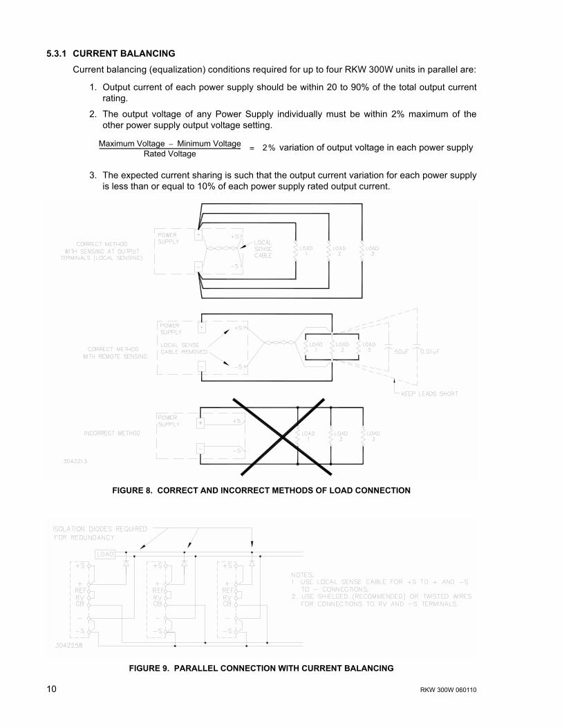
To connect the load for local sensing, connect the +S to (+) terminal and �S to (�) terminal. Theload is connected across DC output (+) and (�) terminals (see Figure 8). For the RKW 3.3-70Kand RKW 5-60K use the two high and the two low output terminals.
5.2 CONNECTING THE LOAD USING REMOTE SENSING
For remote sensing the load is connected as shown in Figure 8. Remote error sensing at the loadterminals compensates for a voltage drop in the connecting wires as indicated in Table 2. Forremote sensing, the sensing cables must be removed from the +S to (+) and �S to (�-) terminals.NOTE: If oscillations set off the overvoltage protection, install one external electrolytic capacitor,rated 470µF min. between the (+) and +S terminals and one between the (�) and �S terminals.
5.3 PARALLEL CONNECTION
RKW 300W Power Supplies can be connected in parallel (with or without N+1 redundancy). Usetwisted or shielded wire for connection to RV and �S terminals. The impedance of the load wiresbetween each power supply and load should be the same.
For a single remote ON-OFF signal to turn off all parallel-connected units, connect together all+RC terminals and connect together all �RC terminals. Figure 9 illustrates connection of up to four(maximum) power supplies in parallel. Output current for a parallel connection operating into asingle load is equalized by connecting the CB terminals as shown. Output current for a parallelconnection operating into a single load is equalized by connecting the CB terminals as shown.Refer to PAR. 5.3.1 for conditions required for proper current equalization (balancing).
N+1 Redundancy. An N+1 system requires one additional power supply than necessary to supplythe load. If one of the parallel-connected units fail, the others will continue to provide power to theload without down time. For redundancy, add isolation diodes as shown in Figure 9.
10 RKW 300W 060110
5.3.1 CURRENT BALANCING
Current balancing (equalization) conditions required for up to four RKW 300W units in parallel are:
1. Output current of each power supply should be within 20 to 90% of the total output currentrating.
2. The output voltage of any Power Supply individually must be within 2% maximum of theother power supply output voltage setting.
variation of output voltage in each power supply
3. The expected current sharing is such that the output current variation for each power supplyis less than or equal to 10% of each power supply rated output current.
FIGURE 8. CORRECT AND INCORRECT METHODS OF LOAD CONNECTION
FIGURE 9. PARALLEL CONNECTION WITH CURRENT BALANCING
Maximum Voltage Minimum Voltage�Rated Voltage
------------------------------------------------------------------------------------------------------- 2%=

RKW 300W 060110 11
5.3.2 MASTER-SLAVE CONFIGURATIONS
Master-slave operation allows the output voltage of all the power supplies connected in parallel tobe adjusted at the same time by using the Vadj control on the designated master power supply.
5.3.2.1 MASTER-SLAVE, MULTIPLE LOADS
Figure 10 shows the master-slave connection of three power supplies in parallel, each having anindependent load, with output voltage controlled by the Vadj control of the master power supply.Use shielded wire (recommended) or twisted wires for connections to RV and �S terminals.
FIGURE 10. PARALLEL CONNECTION, MASTER-SLAVE, MULTIPLE LOADS
5.3.2.2 MASTER-SLAVE, SINGLE LOAD
Figure 11 shows the connection of three power supplies in parallel to a single load. The outputvoltage of all power supplies is controlled by Vadj of the master. Current balancing is implementedto equalize the load current (see PAR. 5.3.1). NOTE: Use shielded wire (recommended) or twistedwires for connections to RV and �S terminals. Match impedance of load wires between eachpower supply and load by using the same wire lengths and wire sizes.
FIGURE 11. PARALLEL CONNECTION, MASTER-SLAVE, SINGLE LOAD
5.4 SERIES CONNECTION
Units may be connected in series to obtain higher voltages. When a number of power supplies areoperating in series, the current rating is to be limited to the rating of the power supply with the low-est rating. Each Power Supply in series should be protected by a diode connected in parallel withthe output as shown in Figure 12. The diode protects against reverse voltages. It should be ratedfor typically, VREVERSE >/= 2 x ΣVOUT of the series connection, IFORWARD >/= 2 xIOUT of the seriesconnection).

12 RKW 300W 060110
FIGURE 12. SERIES CONNECTION
5.5 PRELIMINARY ELECTRICAL CHECK
Connect an adjustable load across the power supply output terminals, on the top side of the frontpanel (see Figure 4). The load must have a dissipation rating of at least 600 Watts. Connect avoltmeter and an oscilloscope across the power supply output terminals (should be linked to therespective sensing terminals, +S and �S). The oscilloscope must be isolated from the source andgrounded at the load. Use an isolation transformer between the test equipment and the AC inputpower (see Figure 13).
Connect the AC input power to the line, neutral and ground terminals (see Figure 4). Turn inputpower on and check the output voltage both with and without load. The output voltage can beadjusted within the published range by using the front panel voltage control trimmer Vadj.
FIGURE 13. FUNCTIONAL CHECKOUT
6. FAN MAINTENANCE
Under most conditions the fan requires no maintenance. Do not use the fan in an environment ofhigh temperature and high humidity that exceeds the temperature and humidity limits given in thePower Supply Specifications (see Table 2). Avoid an environment where corrosive gas may bepresent. If the Power Supply is used in an open or dirty area, a filter should be installed on the airintake side of the fan to prevent the inflow of dust particles. If the Power Supply is used in briny aircare should be taken to keep the salt from entering the Power Supply.
DC

MST SERIES 6/1/10 1
Model Number)______________________________________
Serial Number_______________________________________
Date Purchased:_____________________________________
Date Received:______________________________________
" Send complete Catalog
" Have Sales Engineer Call
Contact via: " E-Mail " Telephone " Fax " S-mail
PRODUCT PURCHASED:
PURCHASE INFORMATION:
REQUEST ADDITIONAL INFORMATION
Registered by:________________________________________
Company Name:______________________________________
Street: ______________________________________________
City:________________________________________________
State:_______________________________________________
Country:_____________________________________________
Zip:_________________________________________________
E-mail: ______________________________________________
FAX:____________________________________________
Phone: _________________________________________
REGISTER TO:
This is to certify that we, KEPCO, INC., (hereinafter called �Company�), Flushing, NY11355 USA, warrants for a period of FIVE YEARS, this instrument known as:
MODEL: __________________________________________
SERIAL NO. _________________________________________
The Company�s products are warranted for a period of five years from date of delivery tobe free from defects in materials and workmanship and to conform to the specificationsfurnished or approved by the Company. Liability under this warranty shall be limited tothe repair or replacement of any defective product at Company�s option.
If any defect within this warranty appears within the warranty period, the Purchaser shallpromptly notify the Company in writing. No material will be accepted for repair orreplacement without written authorization of the Company.
Upon such authorization, and in accordance with instructions of the Company, parts ormaterials for which replacement is requested shall be returned to the Company forexamination, with shipping charges prepaid by the Purchaser. Final determination as towhether a product is actually defective rests with the Company.
This warranty does not extend to any product which has been subjected to misuse,neglect, accident, improper installation, or use in violation of instructions furnished bythe Company. The warranty does not extend to, or apply to, any unit which has beenrepaired or altered outside of the Company�s factory by persons not expressly approvedby the Company.
THE WARRANTY HEREIN CONTAINED IS IN LIEU OF AND EXCLUDES ALL OTHERWARRANTIES, EXPRESS, IMPLIED OR STATUTORY, INCLUDING WITHOUTLIMITATION THE WARRANTY OF MERCHANTABILITY.
Kepco 5 Year Warranty
KEPCO, INC. # 131-38 SANFORD AVENUE, FLUSHING, NY 11355 USA # Tel. 718-461-7000 # Fax. 718-767-1102E-mail: [email protected] # URL: http://www.kepcopower.com
THIS KEPCO PRODUCT IS WARRANTED FOR FIVE YEARS!
WHAT INFLUENCED YOUR CHOICE OF THIS POWER SUPPLY?
" Previous Experience (which Kepco Models do you have?)
______________________________________________________
______________________________________________________
______________________________________________________
" Magazines (which ones?)_____________________________
______________________________________________________
" Trade Shows (which ones?)___________________________
" Directory?__________________________________________
" Kepco Catalog or Brochure?__________________________
" Sales Representative?
" Web Site
" Other (please explain):_____________________________ What products would you like to see Kepco make?
____________________________________________________
____________________________________________________
____________________________________________________
You must register your product to comply with the terms of the warranty. Either fill out the formbelow and mail or fax to Kepco, or for rapid on-line registration go to:
http://www.kepcopower.com/warranty.htm
CUT HERE

FOLD HERE
Pleaseplacestamphere
KEPCO, INC.131-38 SANFORD AVE.FLUSHING, NY 11355 USA
CUT HERE