Operator's Manual 3000 MH, 4000 MH - ddwt.us - D & D World...
65
OWNER’S MANUAL ALLISON 3000 MH 4000 MH
-
Upload
phungduong -
Category
Documents
-
view
220 -
download
1
Transcript of Operator's Manual 3000 MH, 4000 MH - ddwt.us - D & D World...
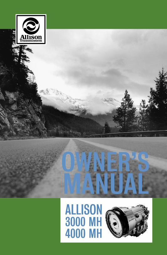
OWNER’SMANUALALLISON3000 MH4000 MH
ATD 5376 Op Manual 5/15/00 11:28 AM Page 1

i
Division of General Motors CorporationP.O. Box 894 Indianapolis, Indiana 46206-0894
OM3349EN
MARCH 2000
Owner’sManual
Allison On-Highway
3000 MH, 4000 MH Series Transmissions(WTEC III Controls)
3000 MH, MHR, MHP, MHPR4000 MH, MHR, MHP, MHPR
Printed in U.S.A. Copyright © 2000 General Motors Corp.

ii
WARNINGS, CAUTIONS, AND NOTES
IT IS YOUR RESPONSIBILITY to be completely familiar with the warnings and cautions described in this handbook. It is, however, important to understand that these warnings and cautions are not exhaustive. Allison Transmission could not possibly know, evaluate, and advise the service trade of all conceivable ways in which service might be done or of the possible hazardous consequences of each way. The vehicle manufacturer is responsible for providing information related to the operation of vehicle systems (including appropriate warnings, cautions, and notes). Consequently, Allison Transmission has not undertaken any such broad evaluation. Accordingly, ANYONE WHO USES A SERVICE PROCEDURE OR TOOL WHICH IS NOT RECOMMENDED BY ALLISON TRANSMISSION OR THE VEHICLE MANUFACTURER MUST first be thoroughly satisfied that neither personal safety nor equipment safety will be jeopardized by the service methods selected.
Proper service and repair is important to the safe, reliable operation of the equipment. The service procedures recommended by Allison Transmission (or the vehicle manufacturer) and described in this handbook are effective methods for performing service operations. Some of these service operations require the use of tools specially designed for the purpose. The special tools should be used when and as recommended.
Three types of headings are used in this manual to attract your attention. These warnings and cautions advise of specific methods or actions that can result in personal injury, damage to the equipment, or cause the equipment to become unsafe.
NOTE:
A note is used when an operating procedure, practice, etc., is essential to highlight.
WARNING:
A warning is used when an operating procedure, practice, etc., if not correctly followed, could result in personal injury or loss of life.
CAUTION:
A caution is used when an operating procedure,practice, etc., if not strictly observed, could result in damage to or destruction of equipment.
TRADEMARK INFORMATION
TRANSYND
TM
is a trademark of Castrol Ltd.DEXRON
®
is a registered trademark of General Motors Corporation.Pro-Link
®
is a registered trademark of Micro Processor Systems, Inc.
TABLE OF CONTENTSPage
Warnings, Cautions, and Notes. . . . . . . . . . . . . . . . . . . . . . . . . . . . . . . . . . . . . ii
INTRODUCTION
Keeping That Allison Advantage . . . . . . . . . . . . . . . . . . . . . . . . . . . . . . . . . . . 1A Brief Description Of The Allison 3000 MH, 4000 MH Series Transmissions 4WTEC III Electronic Control System. . . . . . . . . . . . . . . . . . . . . . . . . . . . . . . . 4Torque Converter . . . . . . . . . . . . . . . . . . . . . . . . . . . . . . . . . . . . . . . . . . . . . . . 5Planetary Gears And Clutches . . . . . . . . . . . . . . . . . . . . . . . . . . . . . . . . . . . . . 8Cooler Circuit . . . . . . . . . . . . . . . . . . . . . . . . . . . . . . . . . . . . . . . . . . . . . . . . . . 8Retarder. . . . . . . . . . . . . . . . . . . . . . . . . . . . . . . . . . . . . . . . . . . . . . . . . . . . . . . 8
SHIFT SELECTORS
Description of Available Types . . . . . . . . . . . . . . . . . . . . . . . . . . . . . . . . . . . . 9Introduction . . . . . . . . . . . . . . . . . . . . . . . . . . . . . . . . . . . . . . . . . . . . . . . . . . . 9Lever Shift Selector . . . . . . . . . . . . . . . . . . . . . . . . . . . . . . . . . . . . . . . . . . . . . 10Pushbutton Shift Selector . . . . . . . . . . . . . . . . . . . . . . . . . . . . . . . . . . . . . . . . . 11Range Selection — Pushbutton And Lever Shift Selectors With Digital Display . . . . . . . . . . . . . . . . . . . . . . . . . . . . . . . . . . 12
DRIVING TIPS
CHECK TRANS Light . . . . . . . . . . . . . . . . . . . . . . . . . . . . . . . . . . . . . . . . . . . 16Diagnostic Codes . . . . . . . . . . . . . . . . . . . . . . . . . . . . . . . . . . . . . . . . . . . . . . . 17Accelerator Control. . . . . . . . . . . . . . . . . . . . . . . . . . . . . . . . . . . . . . . . . . . . . . 17Downshift And Direction Change Inhibitor Feature . . . . . . . . . . . . . . . . . . . . 17Using The Engine To Slow The Vehicle . . . . . . . . . . . . . . . . . . . . . . . . . . . . . 18Using The Hydraulic Retarder . . . . . . . . . . . . . . . . . . . . . . . . . . . . . . . . . . . . . 19Range Preselection . . . . . . . . . . . . . . . . . . . . . . . . . . . . . . . . . . . . . . . . . . . . . . 21Adapting Shifts . . . . . . . . . . . . . . . . . . . . . . . . . . . . . . . . . . . . . . . . . . . . . . . . 21Cold Weather Starts . . . . . . . . . . . . . . . . . . . . . . . . . . . . . . . . . . . . . . . . . . . . . 23Driving On Snow Or Ice . . . . . . . . . . . . . . . . . . . . . . . . . . . . . . . . . . . . . . . . . . 24Rocking Out . . . . . . . . . . . . . . . . . . . . . . . . . . . . . . . . . . . . . . . . . . . . . . . . . . . 24High Fluid Temperature . . . . . . . . . . . . . . . . . . . . . . . . . . . . . . . . . . . . . . . . . . 25Parking Brake . . . . . . . . . . . . . . . . . . . . . . . . . . . . . . . . . . . . . . . . . . . . . . . . . . 26Towing Or Pushing . . . . . . . . . . . . . . . . . . . . . . . . . . . . . . . . . . . . . . . . . . . . . . 26Turning Off The Vehicle . . . . . . . . . . . . . . . . . . . . . . . . . . . . . . . . . . . . . . . . . 26
iii

Page
POWER TAKEOFF OPERATION
Engine-Driven Power Takeoff (PTO). . . . . . . . . . . . . . . . . . . . . . . . . . . . . . . . 27
CARE AND MAINTENANCE
Periodic Inspections . . . . . . . . . . . . . . . . . . . . . . . . . . . . . . . . . . . . . . . . . . . . . 28Prevent Major Problems . . . . . . . . . . . . . . . . . . . . . . . . . . . . . . . . . . . . . . . . . . 28Importance Of Proper Fluid Level . . . . . . . . . . . . . . . . . . . . . . . . . . . . . . . . . . 28Fluid Level Check Using The Pushbutton Or Lever Shift Selector . . . . . . . . . 29Manual Fluid Check Procedure . . . . . . . . . . . . . . . . . . . . . . . . . . . . . . . . . . . . 31Cold Check . . . . . . . . . . . . . . . . . . . . . . . . . . . . . . . . . . . . . . . . . . . . . . . . . . . . 31Hot Check . . . . . . . . . . . . . . . . . . . . . . . . . . . . . . . . . . . . . . . . . . . . . . . . . . . . . 32Recommended Automatic Transmission Fluid And Viscosity Grade . . . . . . . 32Keeping Fluid Clean . . . . . . . . . . . . . . . . . . . . . . . . . . . . . . . . . . . . . . . . . . . . . 34Fluid And Internal Filter Change Interval Recommendations . . . . . . . . . . . . . 34Transmission Fluid Contamination . . . . . . . . . . . . . . . . . . . . . . . . . . . . . . . . . 37Transmission Fluid and Filter Change Procedure . . . . . . . . . . . . . . . . . . . . . . 38
DIAGNOSIS
Diagnostic Codes . . . . . . . . . . . . . . . . . . . . . . . . . . . . . . . . . . . . . . . . . . . . . . . 41Diagnostic Code Display Procedure . . . . . . . . . . . . . . . . . . . . . . . . . . . . . . . . . 42Diagnostic Code Listings and Procedures . . . . . . . . . . . . . . . . . . . . . . . . . . . . 44
ABBREVIATIONS AND DEFINITIONS
Abbreviations and Definitions . . . . . . . . . . . . . . . . . . . . . . . . . . . . . . . . . . . . . 51
CUSTOMER SERVICE
Owner Assistance . . . . . . . . . . . . . . . . . . . . . . . . . . . . . . . . . . . . . . . . . . . . . . . 53Service Literature . . . . . . . . . . . . . . . . . . . . . . . . . . . . . . . . . . . . . . . . . . . . . . . 55Allison Transmission Distributors . . . . . . . . . . . . . . . . . . . . . . . . . . . . . . . . . . 56Allison Transmission Regional Offices . . . . . . . . . . . . . . . . . . . . . . . . . . . . . . 59
iv

M H S E R I E S
INTRODUCTION
KEEPING THAT ALLISON ADVANTAGE
Allison MH Series transmissions provide many advantages for the driver who must “stop and go” or change speeds frequently. Driving is easier, safer, and more efficient.
The MH Series transmissions are rugged and designed to provide long, trouble-free service. This handbook will help you gain maximum benefits from your ALLISON-equipped vehicle.
HILL
SPEEDZONE
R R
STOP
Y I E L D
V01724
1
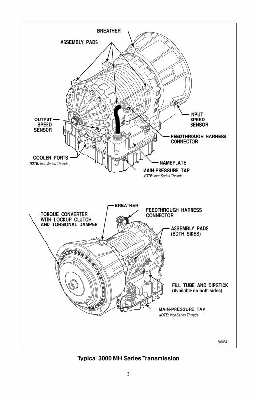
Typical 3000 MH Series Transmission
OUTPUTSPEED
SENSOR
NAMEPLATE
INPUTSPEEDSENSOR
ASSEMBLY PADS
MAIN-PRESSURE TAPNOTE: Inch Series Threads
BREATHER
FEEDTHROUGH HARNESSCONNECTOR
COOLER PORTSNOTE: Inch Series Threads
V06341
ASSEMBLY PADS(BOTH SIDES)
BREATHER
MAIN-PRESSURE TAPNOTE: Inch Series Threads
FEEDTHROUGH HARNESSCONNECTORTORQUE CONVERTER
WITH LOCKUP CLUTCHAND TORSIONAL DAMPER
FILL TUBE AND DIPSTICK(Available on both sides)
2

3
Typical 4000 MH Series Transmission
TURBINE SPEEDSENSOR
MOUNTINGPAD
INPUT SPEEDSENSOR
NAMEPLATE
FILL TUBE AND DIPSTICKOUTPUT SPEED
SENSOR
FEEDTHROUGHHARNESS
CONNECTOR
V06342
COOLER PORTS
MAIN-PRESSURE TAP
MOUNTING PAD(BOTH SIDES)
COOLER PORTS
FEEDTHROUGHHARNESSCONNECTOR
BREATHER
BREATHER

A BRIEF DESCRIPTION OF THE ALLISON 3000 MH, 4000 MH SERIES TRANSMISSIONS
Included in the Allison On-Highway Transmission family are the 3000 MH and 4000 MH Series transmissions. The transmissions described in this handbook include the WTEC III control system, a torque converter with lockup and torsion damper, and three planetary gear sets. These transmissions may also contain an integral retarder (the R in the model name) or power takeoff (PTO, the P in the model name).
WTEC III ELECTRONIC CONTROL SYSTEM
The WTEC III control system is standard on all 3000 MH and 4000 MH Series. The system consists of five major components connected by customer-furnished wiring harnesses — Electronic Control Unit (ECU), engine throttle position sensor (or direct electronic communication), three speed sensors, remote shift selector, and control module (which contains solenoid valves and a pressure switch). The throttle position sensor (or engine-to-transmission communication link), speed sensors, pressure switch, and shift selector transmit information to the ECU. The ECU processes this information and then sends signals to actuate specific solenoids located on the control module in the transmission. These solenoids control both oncoming and offgoing clutch pressures to provide closed-loop shift control by matching rpm during a shift to a previously established desired profile that is programmed into the ECU.
A feature of WTEC III controls is “autodetect.” Autodetect is active within the first several engine starts, depending upon the component or sensor being detected. These engine start cycles begin from when the transmission is installed during vehicle manufacture. Autodetect searches for the presence of the following transmission components or data inputs:
Seek help from your nearest Allison Transmission service outlet when any of the above items are present, but are not responding properly.
Retarder Present, Not Present
Oil Level Sensor (OLS) Present, Not Present
Throttle Analog, J 1587, J 1939
Engine Coolant Temperature Analog, J 1939, J 1587
4

Another feature of the 3000 MH and 4000 MH Series transmission is its ability to adapt or “learn” as it operates. Each shift is measured electronically, stored and used by the ECU to adapt or “learn” the optimum conditions for future shifts.
TORQUE CONVERTER
The torque converter consists of three elements — pump, turbine, and stator. The pump is the input element and is driven directly by the engine. The turbine is the output element and is hydraulically driven by the pump. The stator is the reaction (torque multiplying) element. When the pump turns faster than the turbine, the torque converter is multiplying torque. When the turbine approaches the speed of the pump, the stator starts to rotate with the pump and turbine. When this occurs, torque multiplication stops and the torque converter functions as a fluid coupling.
The lockup clutch is located inside the torque converter and consists of three elements — piston, clutch plate/damper, and backplate. The piston and backplate are driven by the engine. The clutch plate/damper, located between the piston and the backplate, is splined to the converter turbine. The lockup clutch is engaged and released in response to electronic signals from the ECU. Lockup clutch engagement provides a direct drive from the engine to the transmission gearing. This eliminates converter slippage and provides maximum fuel economy and vehicle speed. The torsional damper absorbs engine torsional vibration to prevent transmission through the powertrain.
The lockup clutch releases at lower speeds or when the ECU detects conditions requiring it to be released.
NOTE: If the shift quality of low mileage vehicles, or vehicles with new or recalibrated ECUs is unacceptable, follow the procedure explained in the ADAPTING SHIFTS section.
NOTE: Allison WTEC III electronic control systems are designed and manufactured to comply with all FCC and other guidelines regarding radio frequency interference/electromagnetic interference (RFI/EMI) for transportation electronics. Manufacturers, assemblers, and installers of radio-telephone or other two-way communication radios have the sole responsibility to correctly install and integrate those devices into Allison 3000 MH and 4000 MH Series transmission-equipped vehicles to customer satisfaction.
The ECU is programmed to provide the most suitable operating characteristics for a specific application. This handbook does not attempt to describe all of the possible combinations. The information contained herein describes only the operating characteristics most frequently requested by the vehicle manufacturer.
5

6
OIL
LEV
EL S
ENSO
R
P2 M
ODU
LE
P1 M
ODU
LE
CONV
ERTE
R M
ODU
LE• T
URBI
NE• P
UMP
• LO
CKUP
CLU
TCH/
DAM
PER
• STA
TOR
CONV
ERTE
R H
OUS
ING
MO
DULE
• CO
NVER
TER
HO
USIN
GRO
TATI
NG C
LUTC
H M
ODU
LE• C
1 C
LUTC
H• C
2 C
LUTC
H• T
URBI
NE S
HAFT
CONT
ROL
MO
DULE
• ELE
CTRO
-HYD
RAUL
IC C
ONT
ROLS
MAI
N S
HAFT
MO
DULE
• MAI
N S
HAFT
• P2
SUN
• P3
SUN
MAI
N HO
USIN
G M
ODU
LE• M
AIN
HO
USIN
G• C
3 CL
UTCH
• C4
CLUT
CH• C
5 CL
UTCH
FRO
NT S
UPPO
RT/O
IL P
UMP
MO
DULE
• FRO
NT S
UPPO
RT• O
IL P
UMP
REAR
CO
VER
MO
DULE
• OUT
PUT
SHA
FT• P
3• C
5 P
ISTO
N
V033
48.0
2
Typ
ical
300
0 M
H S
erie
s Tr
ansm
issi
on
Cro
ss S
ecti
on

7
ROTA
TING
CLU
TCH
MO
DULE
C
1 C
LUTC
H
C2
CLU
TCH
T
URBI
NE S
HAFT
CONT
ROL
MO
DULE
E
LECT
RO-H
YDRA
ULIC
CO
NTRO
LS
P1 M
ODU
LE
P2 M
ODU
LE
MAI
N H
OUS
ING
MO
DULE
M
AIN
HO
USIN
G
C3
CLU
TCH
C
4 C
LUTC
H
C5
CLU
TCH
MAI
N S
HAFT
MO
DULE
M
AIN
SHA
FT
P2
SUN
P
3 S
UN
REAR
CO
VER
MO
DULE
O
UTPU
T S
HAFT
P
3 M
ODU
LE
C5
PIS
TON
V063
43
CONV
ERTE
R M
ODU
LETU
RBIN
EPU
MP
STAT
OR
LOCK
UPCL
UTCH
/DAM
PER
CONV
ERTE
R H
OUS
ING
MO
DULE
CONV
ERTE
R H
OUS
ING
FRO
NT S
UPPO
RT/O
IL P
UMP
MO
DULE
FRO
NT S
UPPO
RT
OIL
PUM
P
Typ
ical
400
0 M
H S
erie
s Tr
ansm
issi
on
Cro
ss S
ecti
on

PLANETARY GEARS AND CLUTCHES
A series of three helical planetary gear sets and shafts provides the mechanical gear ratios and direction of travel for the vehicle. The planetary gear sets are controlled by five multiplate clutches that work in pairs to produce six forward speeds and one reverse speed. The clutches are applied and released hydraulically in response to electronic signals from the ECU to the appropriate solenoids.
COOLER CIRCUIT
The transmission fluid is cooled by an integral (transmission-mounted) or remote-mounted oil cooler. Connections to the cooling circuit are located at the front or rear of the transmission to facilitate installation of remote cooler lines. On shallow sump models, only rear ports are available. On retarder models, only rear cooler ports may be used. The integral cooler is located on the lower rear portion of the transmission, replacing the remote cooler manifold. Integral cooler oil ports are internal requiring only coolant to be routed to and from the cooler.
RETARDER
The self-contained retarder is at the output of the transmission and consists of a vaned rotor which rotates in a vaned cavity. The rotor is splined to and driven by the output shaft. An external accumulator holds transmission fluid until the retarder is activated. When the retarder is activated, the fluid in the accumulator is pressurized by the vehicle air system and directed into the retarder cavity. The interaction of the fluid with the rotating and stationary vanes causes the retarder rotor speed, and hence the output shaft, to decrease and slow the vehicle or to limit speed on a downhill grade. See Page 19 for additional retarder information.
When the retarder is deactivated, the retarder cavity is evacuated and the accumula-tor is recharged with fluid.
8
M H S E R I E S
SHIFT SELECTORS
DESCRIPTION OF AVAILABLE TYPES
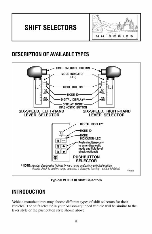
Typical WTEC III Shift Selectors
INTRODUCTION
Vehicle manufacturers may choose different types of shift selectors for their vehicles. The shift selector in your Allison-equipped vehicle will be similar to the lever style or the pushbutton style shown above.
1
2
3
4
5
D
N
RMODE
R
N
D
5
4
3
2
1MODE
R
N
D
MODE
V06344
SIX-SPEED, LEFT-HANDLEVER SELECTOR
HOLD OVERRIDE BUTTON
DISPLAY MODE/DIAGNOSTIC BUTTON
MODE ID
DIGITAL DISPLAY✽
MODE BUTTON
MODE INDICATOR(LED)
SIX-SPEED, RIGHT-HANDLEVER SELECTOR
MODE ID
MODEINDICATOR (LED)
Push simultaneouslyto enter diagnosticmode and fluid levelcheck (optional)
NOTE: Number displayed is highest forward range available in selected position.Visually check to confirm range selected. If display is flashing – shift is inhibited.
✽
DIGITAL DISPLAY✽
PUSHBUTTONSELECTOR
9

With an Allison-equipped vehicle, it is not necessary to select the right moment to upshift or downshift during changing road and traffic conditions. The Allison MH Series does it for you. However, knowledge of the shift selector positions, ranges available, and when to select them, will make vehicle control even easier. It is recommended to select lower ranges when descending long grades (with and without retarder) to reduce wear on service brakes. Be sure to read RANGE SELECTION, which begins on Page 12, for related information.
LEVER SHIFT SELECTOR
General Description. The lever shift selector is an electro-mechanical control. The typical lever positions provided are R (Reverse), N (Neutral), D (Drive) and some number of lower forward range positions. The MH Series transmissions can be programmed to have four, five, or six forward ranges. The shift selector positions provided should agree with the programming of the transmission electronic control unit. The lever selector contains a hold override button, a MODE button, a digital display, and a display mode button.
Hold Override Button. The lever shift selector has three locked positions to prevent accidentally selecting R (Reverse), N (Neutral), or D (Drive). Select R, N, or D by pressing the hold override button and moving the lever to the desired position. Once D (Drive) is selected, lower forward range positions may be selected without pressing the hold override button.
MODE Button. The MODE button may allow the driver to enable a secondary shift schedule or other special function that has been previously programmed into the electronic control unit at the request of the OEM. For example, the OEM for a motor home may have provided a secondary shift schedule for improved fuel economy. The name of the special function (ECONOMY) should appear on the MODE ID label adjacent to the MODE button. Pressing the MODE button activates the ECONOMY shift schedule and illuminates the MODE INDICATOR (LED). Other special functions which may be activated by the MODE button are D1 selection or PTO enable. The MODE button is also used to view diagnostic code information. Refer to the DIAGNOSIS section for further explanation. After viewing the first diagnostic code which appears in the digital display, press the MODE button to view the 2nd diagnostic code logged. Repeat this procedure to view the 3rd, 4th, and 5th code positions. The code displayed is active when the MODE INDICATOR (LED) is illuminated.
Digital Display. During normal operation, when D (Drive) is selected, the digital display shows the highest forward range attainable for the shift schedule in use. Abnormal operation is also indicated by the digital display. When all segments of
NOTE: Visually check the digital display whenever the lever is moved to be sure that the range selected is shown (i.e., if the N (Neutral) button is pressed, N should appear in the digital display).
10

the digital display are illuminated for more than 12 seconds, the ECU did not complete initialization. When the digital display is blank, there is no power to the selector. When the display shows a “ ” (cateye), a selector-related fault code has been logged. Conditions which illuminate the CHECK TRANS light will disable the shift selector and the digital display will show the range actually attained. See Page 16 for detailed explanation of the CHECK TRANS light. The transmission will not shift into range if a CHECK TRANS code is active. When the display shows either R or D has been requested and the display is flashing, the requested range has not been achieved due to an inhibit function. Some inhibit functions are vehicle-related and will not result in diagnostic codes. Some examples are mentioned in the Range Selection section which follows. Check for active codes if no other inhibit function has been located. Refer to the DIAGNOSIS section for information on accessing codes using the shift selector. Once D (Drive) is attained, the transmission will shift into the lowest range programmed for the D (Drive) position, usually first.
Display Mode/Diagnostic Button. Allows access to optional fluid level check information and diagnostic code information. Press the display mode/diagnostic button once to obtain transmission fluid level information (when oil level sensor is present) and a second time to obtain diagnostic code information.
PUSHBUTTON SHIFT SELECTORGeneral Description. The pushbutton shift selector has R, N, D, �, �, a MODE button, and a digital display.
R Pushbutton. Press this button to select Reverse.
N Pushbutton. Press this button to select Neutral.
D Pushbutton. Press this button to select Drive. The highest forward range available will appear in the digital display window. The transmission will start out in the lowest available forward range and advance automatically to the highest range.
�, � (Arrow) Buttons. When a lower range is desired, after D (Drive) has been pressed, press the � (Down) arrow button until the desired range is shown in the display window. Likewise, if the transmission is held in a low range by the � (Down) arrow, press the � (Up) arrow to request the next higher range. Continuous pressing of either the � (Up) or � (Down) arrow buttons will request the highest or lowest range available.
Access fluid level data and diagnostic codes with the pushbutton selector by pressing the � (Up) and � (Down) arrow buttons at the same time. Refer to Page 29, FLUID LEVEL CHECK USING THE PUSHBUTTON OR LEVER SHIFT SELECTOR, or Page 41, DIAGNOSIS for further information. Fluid level information is displayed (if optional oil level sensor is present) after the first simultaneous press. Press both buttons again to obtain diagnostic data.
MODE Button and Digital Display. Same function as described in the lever selector above.
11

RANGE SELECTION — PUSHBUTTON AND LEVER SHIFT SELECTORS WITH DIGITAL DISPLAY
RANGE SELECTION
NOTE: Visually check the digital display window whenever a button is pushed or the lever is moved to be sure that the range selected is shown (i.e., if the N (Neutral) button is pressed, N should appear in the digital display). A flashing display indicates that the range selected was not attained due to an active inhibit.
R Completely stop the vehicle and let the engine return to idle before shifting from a forward range to Reverse or from Reverse to a forward range. The LED window on the Reverse pushbutton will illuminate and Reverse will be attained.
1
2
3
4
5
D
N
RMODE
R
N
D
MODE
V03497.01
PUSHBUTTONSELECTOR
TYPICALLEVERSELECTOR
WARNING: If you leave the vehicle and the engine is running, the vehicle can move suddenly and you or others could be injured. If you must leave the engine running, do not leave the vehicle until you:
• Put the transmission in N (Neutral)…and• Ensure that the engine is at low idle rpm (below 1000)…and• Apply the parking brake and emergency brakes and make sure
they are properly engaged…and• Chock the wheels and take any other steps necessary to keep the
vehicle from moving.
WARNING: R (Reverse) may not be obtained due to an active inhibitor. Always be sure that “R” is not flashing whenever R (Reverse) is selected. See DOWNSHIFT AND DIRECTION CHANGE INHIBITOR FEATURE on Page 17. Check for active diagnostic codes if R (Reverse) is not attained.
CAUTION: Do not idle in R (Reverse) for more than five minutes. Extended idling in R (Reverse) may cause transmission overheat-ing and damage. Always select N (Neutral) whenever time at idle exceeds five minutes.
12
(continued on next page)

RANGE SELECTION
N Use Neutral when you start the engine, to check vehicle accessories, and for extended periods of engine idle operation (longer than five minutes). For vehicles equipped with the pushbutton selector, Neutral is automatically set by the ECU during startup. For vehicles equipped with the lever selector, the vehicle will not start until Neutral has been manually selected. If the vehicle starts in any range other than Neutral, seek service immediately. Neutral is also used during stationary operation of the power takeoff (if your vehicle is equipped with a PTO). The digital display will show N when Neutral is selected. Be sure to select N (Neutral) before turning off the vehicle engine.
RANGE SELECTION — PUSHBUTTON AND LEVER SHIFT SELECTORS WITH DIGITAL DISPLAY (cont’d)
1
2
3
4
5
D
N
RMODE
R
N
D
MODE
V03497.01
PUSHBUTTONSELECTOR
TYPICALLEVERSELECTOR
WARNING: When starting the engine, make sure the service brakes are applied. Failure to apply the service brakes may result in unexpected vehicle movement.
WARNING: Vehicle service brakes, parking brake, or emergency brake must be applied whenever N (Neutral) is selected to prevent unexpected vehicle movement. Selecting N (Neutral) does not apply vehicle brakes, unless an auxiliary system to apply the parking brake is installed (see Operator’s Manual for the vehicle).
WARNING: If you let the vehicle coast in N (Neutral), there is no engine braking and you could lose control. Coasting can also cause severe transmission damage. To help avoid injury and property damage, do not allow the vehicle to coast in N (Neutral).
13
(continued on next page)

RANGE SELECTION
NOTE: Turn off the vehicle HIGH IDLE switch, if present, before shifting from N (Neutral) to D (Drive) or R (Reverse). D (Drive) or R (Reverse) will not be attained unless the shift is made with the engine at idle. Also, be aware of other interlocks that would prevent obtaining D (Drive) or R (Reverse). Examples are “wheelchair lift not stored” and “service brakes not applied” (service brake interlock present).
D The transmission will initially attain first range when Drive is selected. As speed increases, the transmission automatically upshifts through each range. As the vehicle slows, the transmission automatically downshifts. The light on the Drive pushbutton will illuminate and the appropriate range of Drive will be attained.
RANGE SELECTION — PUSHBUTTON AND LEVER SHIFT SELECTORS WITH DIGITAL DISPLAY (cont’d)
1
2
3
4
5
D
N
RMODE
R
N
D
MODE
V03497.01
PUSHBUTTONSELECTOR
TYPICALLEVERSELECTOR
WARNING: Even though D (Drive) is selected, it may not be obtained due to an active inhibitor. Always be sure that “D” is not flashing whenever D (Drive) is selected. See DOWNSHIFT AND DIRECTION CHANGE INHIBITOR FEATURE on Page 17. Check for active diagnostic codes if D (Drive) is not attained.
CAUTION: Do not idle in D (Drive) for more than five minutes. Extended idling in D (Drive) may cause transmission overheating and damage. Always select N (Neutral) if time at idle is longer than five minutes.
14
(continued on next page)

RANGE SELECTION
6*5*4*32
Occasionally, road conditions, load, or traffic conditions will make it desirable to restrict automatic shifting to a lower range. Lower ranges provide greater engine braking for going down grades (the lower the range, the greater the braking effect).
The pushbutton selector utilizes arrow buttons to select individual forward ranges. Push the � (Up) or � (Down) arrow to the desired range. The digital display will show your choice of range. Even though a lower range was selected, the transmission may not downshift until vehicle speed is reduced (this prevents excessive engine speed in the lower range).
* Actual ranges available depend on programming by vehicle manufacturer.
1 Use this range when pulling through mud and deep snow, whenmaneuvering in tight spaces, or while driving up or down grades. First range provides the vehicle with its maximum driving torque and maximum engine braking effect. For vehicles equipped with the pushbutton selector, push the � (Down) arrow until first range appears in the select window.
RANGE SELECTION — PUSHBUTTON AND LEVER SHIFT SELECTORS WITH DIGITAL DISPLAY (cont’d)
1
2
3
4
5
D
N
RMODE
R
N
D
MODE
V03497.01
PUSHBUTTONSELECTOR
TYPICALLEVERSELECTOR
WARNING: If you just downshift or just use service brakes when going downhill, you can lose control and cause injury and property damage. To help avoid loss of control, use a combination of downshifting, braking, and other retarding devices. Downshifting to a lower transmission range increases engine braking and helps you to maintain control. The transmission has a feature to prevent automatic upshifting above the lower range selected. However, during downhill operation, if engine governed speed is exceeded in the lower range, the transmission may upshift to the next higher range. This will reduce braking and could cause a loss of control. Apply the vehicle brakes or other retarding device to prevent exceeding engine governed speed in the lower range selected.
15

M H S E R I E S
DRIVING TIPS
CHECK TRANS LIGHT
The electronic control system is programmed to inform the operator of a problem with the transmission system and automatically take action to protect the operator, vehicle, and transmission. When the Electronic Control Unit (ECU) detects a problem condition, the ECU restricts shifting, turns on the CHECK TRANS light on the instrument panel, and registers a diagnostic code.
Each time the engine is started, the CHECK TRANS light will illuminate, then turn off after a few seconds. This momentary lighting is to show that the status light circuits are working properly. If the CHECK TRANS light does not illuminate during ignition, or if the light remains on after ignition, the system should be checked immediately.
Continued illumination of the CHECK TRANS light during vehicle operation (other than start-up) indicates that the ECU has signaled a diagnostic code. Illumination of the CHECK TRANS light is accompanied by a flashing display from the shift selector. The shift selector display will show the actual range attained and the transmission will not respond to shift selector requests.
The indications from the shift selector are provided to inform the operator that the transmission is not performing as designed and is operating with reduced capabilities. Before turning the ignition off, the transmission may be operated for a short time in the selected range in order to “limp home” for service assistance. Service should be performed immediately in order to minimize the potential for damage to the transmission.
When the CHECK TRANS light comes on and the ignition switch is turned off, the transmission will remain in N (Neutral) until the condition causing the CHECK TRANS light is corrected.
NOTE: For some problems, diagnostic codes may be registered without the ECU activating the CHECK TRANS light. Your Allison Transmission authorized service outlet should be consulted whenever there is a transmission-related concern. They have the equipment to check for diagnostic codes and to correct problems which arise.
16
Generally, while the CHECK TRANS light is on, upshifts and downshifts will be restricted and direction changes will not occur. Lever and pushbutton shift selectors do not respond to any operator shift requests while the CHECK TRANS light is illuminated. The lockup clutch is disengaged when transmission shifting is restricted or during any critical transmission malfunction.
DIAGNOSTIC CODES
See detailed information in the DIAGNOSIS section.
ACCELERATOR CONTROL
The position of the accelerator pedal influences the timing at which automatic shifting occurs. When the pedal is fully depressed, upshifts will occur automatically at high engine speeds. A partially depressed position of the pedal will cause the upshifts to occur at lower engine speeds. An electronic throttle position signal tells the ECU how much the operator has depressed the pedal. Excessive throttle position affects directional change shifts (shifts from N (Neutral) to D (Drive) or R (Reverse)).
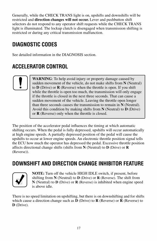
DOWNSHIFT AND DIRECTION CHANGE INHIBITOR FEATURE
There is no speed limitation on upshifting, but there is on downshifting and for shifts which cause a direction change such as D (Drive) to R (Reverse) or R (Reverse) toD (Drive).
WARNING: To help avoid injury or property damage caused by sudden movement of the vehicle, do not make shifts from N (Neutral) to D (Drive) or R (Reverse) when the throttle is open. If you shift while the throttle is open too much, the transmission will only engage if the throttle is closed in the next three seconds. That can cause a sudden movement of the vehicle. Leaving the throttle open longer than three seconds causes the transmission to remain in N (Neutral). Avoid this condition by making shifts from N (Neutral) to D (Drive) or R (Reverse) only when the throttle is closed.
NOTE: Turn off the vehicle HIGH IDLE switch, if present, before shifting from N (Neutral) to D (Drive) or R (Reverse). The shift fromN (Neutral) to D (Drive) or R (Reverse) is inhibited when engine speed is above idle.
17

Manual range downshifts will not occur until a calibration value of output speed is reached. When a range downshift is manually selected and the transmission output speed is above the calibration value, the transmission will stay in the range it was in even though a lower range was requested. Apply the vehicle service brakes or some retarding device to reduce the transmission output speed to the calibration value and then the shift to the lower range will occur.
Directional shifts, D (Drive) to R (Reverse) or R (Reverse) to D (Drive), will not occur if selected when throttle position, engine speed, or transmission output speed is above the calibration limit for a calibration time period. The current calibration time period for engine speed is 0.5 seconds and for throttle position and output speed is three seconds. Shifts from N (Neutral) to D (Drive) or R (Reverse) are also inhibited when the ECU has been programmed (by input/output function) to detect that auxiliary equipment is in operation and the shift should not be allowed. When a directional shift is inhibited, the ECU will put the transmission in N (Neutral) and the digital display, if present, will flash the letter of the range selected (D or R). Reselect D (Drive) or R (Reverse) when engine throttle, engine speed, and transmission output speed are below the calibration value. With a pushbutton selector, just depress the desired pushbutton again. With a lever selector, move the lever to N (Neutral) and then to the desired range. When a direction change shift is requested and the engine throttle, engine speed, and transmission output speed drop below the calibration value during the calibration time interval, the shift to D (Drive) or R (Reverse) will occur. For example, if the transmission output speed was just above the calibration limit when R (Reverse) was selected, but dropped below the limit during the next three seconds, the shift to R (Reverse) would occur (assuming that engine was at idle and throttle was closed).
USING THE ENGINE TO SLOW THE VEHICLE
To use the engine as a braking force, select the next lower range. If the vehicle is exceeding the maximum speed for this range, use the service brakes and/or retarder
WARNING: If you just downshift or just use service brakes when going downhill, you can lose control and cause injury and property damage. To help avoid loss of control, use a combination of downshifting, braking, and other retarding devices. Downshifting to a lower transmission range increases engine braking and helps you to maintain control. The transmission has a feature to prevent automatic upshifting above the lower range selected. However, during downhill operation, if engine governed speed is exceeded in the lower range, the transmission may upshift to the next higher range. This will reduce braking and could cause a loss of control. Apply the vehicle brakes or other retarding device to prevent exceeding engine governed speed in the lower range selected.
18

to slow the vehicle. When a lower speed is reached, the ECU will automatically down-shift the transmission. Engine braking provides good speed control for going down grades. When the vehicle is heavily loaded, or the grade is steep, it may be desirable to preselect a lower range before reaching the grade. If engine-governed speed is exceeded, the transmission will upshift automatically to the next range.
USING THE HYDRAULIC RETARDER
Regardless of the type of Allison retarder controls on your vehicle, the following safety features are common to each configuration:
• The retarder can be disabled when inclement weather or slippery road conditions are present.
• Vehicle brake lights should always be on when the retarder is applied (periodically verify that they are working).
• Anti-lock brake systems send a signal to the transmission ECU to indicate that the brake system is activated.
A hydraulic retarder is available on all of the models covered in this manual. The retarder is activated and controlled in various ways. The control depends upon the vehicle type and particular duty cycle. Both manual and automatic controls are available. Automatic controls are applied by the ECU. Some types of controls and the amount of retarder application are shown in Table 1 on Page 20.
WARNINGS: DO NOT USE THE RETARDER DURING INCLEMENT WEATHER OR WHEN ROAD SURFACES ARE SLIPPERY. De-energize the retarder at the master control switch.
To help avoid injury or property damage caused by loss of vehicle control, be ready to apply vehicle brakes or other retarding device if the transmission retarder does not apply. If a retarder is present but is not detected by “autodetect”, the retarder will not function. Be sure to check for proper retarder function periodically. Whenever the retarder does not apply, seek service help immediately.
On vehicles which have the primary retarder control based upon closed throttle position, brake pedal position, or brake apply pressure, always manually disable the retarder controls during inclement weather or slippery road conditions.
NOTE: The retarder is automatically disabled (and the lockup clutch is disengaged) whenever the vehicle ABS (anti-lock brake system) is active. However, in case the ABS system malfunctions, it is recommended that the retarder enable switch, if present, be disabled.
19

20
The presence of a retarder must be “autodetected” as part of the WTEC III control system.
WARNING: If your transmission has a retarder but it is not functioning, it may not have been “autodetected” during vehicle manufacture. Go immediately to your nearest Allison Transmission service outlet to have “autodetect” reset or the retarder enabled using the Pro-Link®.
NOTE: When reduced retarder performance is observed, be sure that the transmission fluid level is within the operating band on the dipstick. Low fluid level is a common cause for retarder performance complaints.
NOTE: The retarder requires about one second to reach full capacity requested. Be sure to anticipate this delay when using the retarder. Anticipation will prevent unnecessary service brake applications during non-emergency stops.
Table 1. Types of Retarder Control
Type Description Amount of ApplicationManual Separate apply pedal Zero to Full apply
Hand lever * Six levels based on lever position
Automatic Auto “Full On” * “Full On” when closed throttle sensed
Brake Pressure Apply **
Single pressure switch
Three pressure switches
Off or “Full On” (based on brake pressure)
1 ⁄ 3, 2 ⁄ 3, or “Full On” (based on brake pressure)
Pedal Position ** Special brake pedal 1 ⁄ 3, 2 ⁄ 3, or “Full On” (based on pedal position)
Combinations of the above systems **
Auto “half-on” plus pressure switch *
Half capacity at closed throttle or “Full On” with brake pressure
Auto “1 ⁄ 3 on” plustwo pressure switches *
1 ⁄ 3, capacity at closed throttle or 2 ⁄ 3 and“Full On” with brake pressure
Hand lever pluspressure switch *
6 levels of modulation with lever, or “Full On” with brake pressure
Foot pedal pluspressure switch
Full modulation with separate pedal, or “Full On” with brake pressure
Hand lever plus interface for special pedal *
6 levels of modulation with lever, or 3 levels of modulation based on pedal position
NOTE: * These control systems may apply the retarder at high speed on grades when the vehicle has road speed limiting and the retarder is enabled.
** For retarder apply systems integrated with the service brake system, the retarder is most effective when applied with light brake pedal pressure for 1–2 seconds to allow the retarder to fully charge. Added pedal pressure can be applied when more aggressive braking is desired.

Contact your vehicle manufacturer to understand how the retarder controls have been integrated into your vehicle.
RANGE PRESELECTIONRange preselection means selecting a lower range to match driving conditions you encounter or expect to encounter. Learning to take advantage of preselected shifts will give you better control on slick or icy roads and on downgrades. Downshifting to a lower range increases engine braking. The selection of a lower range often prevents cycling between that range and the next higher range on a series of short up-and-down hills.
ADAPTING SHIFTS
When poor shift quality is due to the installation of a new or recalibrated ECU, use the following procedure to restore good shift quality by completing a prescribed number of shifts in a relatively short time instead of over several days of operation.
CAUTION: Observe the following cautions when driving a vehicle equipped with a retarder.
THE RETARDER WORKS ONLY WHEN THE ENGINE IS AT CLOSED THROTTLE.
OBSERVE TRANSMISSION AND ENGINE TEMPERATURE LIMITS AT ALL TIMES. Select the lowest possible transmission range to increase the cooling system capacity and total retardation available.
In the event of OVERHEATING, DECREASE THE USE OF THE RETARDER; USE THE SERVICE BRAKES TO SLOW THE VEHICLE.
OBSERVE THE RETARDER/SUMP “OVERTEMP” LIGHT to ensure that it responds properly to retarder temperature.
NOTE: Transmission oil level must be set correctly for highest retarder effectiveness. As much as 2 liters (2 quarts) too high or too low can reduce retarder effectiveness and increase transmission temperature.
NOTE: Preselecting during normal operation may result in reduced fuel economy.
NOTE: Shift concerns may indicate the transmission has never had the shifts fully adapted.
21

Adaptive does not function below 100 degrees Fahrenheit transmission sump temperature. Normal running hot sump temperature is recommended before this procedure is followed.
Check transmission sump level and assure it is set to “Hot Full” at normal running hot sump temperature before this procedure is followed.
All segments of this procedure are to be repeated a minimum of 5 times or until shift quality variation is indistinguishable from shift to shift.
1. From Neutral, with parking brake set and service brakes applied via foot pedal, select the following sequence: Drive, Neutral, Reverse, Neutral, Drive, Reverse, Drive, Neutral. Allow each shift to fully complete before selecting the next shift.
2. Release all brakes and perform this sequence: Wide Open Throttle (WOT) 1–2; once shift is complete, release the throttle to closed and decelerate to just prior to the Closed Throttle (CT) 2–1 and perform a Step Thru (ST) 2–1 by going to WOT.
3. Continue the process initiated in Step 2 for each Upshift and Downshift combination available. Example: Wide Open Throttle (WOT) 2–3; once shift is complete, release the throttle to closed and decelerate to just prior to the Closed Throttle (CT) 3–2 and perform a Step Thru (T) 3–2 by going to WOT. Repeat for the WOT 3–4/ST 4–3, WOT 4–5/ST 5–4, WOT 5–6/ST 6–5.
4. From a Stop, release vehicle brakes and perform a set of Part Throttle(PT ~ 50% to 60%) Upshifts to the highest attainable range for the vehicle. Release the throttle to Closed and, using Light vehicle brakes, decelerate to a stop.
5. From a Stop, release vehicle brakes and perform Part Throttle (PT ~ 50% to 60%) Upshifts to the 3rd range. Release the throttle to Closed and, using Moderate to Heavy vehicle brakes (NOT panic or wheel lock), decelerate to a stop.
6. From a Stop, release vehicle brakes and perform a set of Wide Open Throttle Upshifts to the highest attainable range for the vehicle. Release the throttle to Closed and Preselect Down to 1st Range using the shift selector. Use light vehicle brakes, decelerate to a stop.
NOTE: If the vehicle is equipped with an output retarder or engine brake system, these systems should be turned off for this segment.
NOTE: Braking should be aggressive but not to the level that would cause passenger complaints. If the vehicle is equipped with an output retarder or engine brake system, these systems should be turned off for this segment.
22

23
7. If the vehicle is equipped with a retarder or engine brake, turn that system on for this segment. From a Stop, release vehicle brakes and perform a set of Wide Open Throttle Upshifts to the highest attainable range for the vehicle. Release the throttle to Closed and, using Light vehicle brakes and the retarder or engine brake, decelerate vehicle to a stop.
8. Approach the grade in the highest safely attainable range and hold the throttle steady at WOT and allow the vehicle to perform the Powered Downshifts as required to ascend the grade.
9. Approach the grade in the highest safely attainable range and hold the throttle steady at Part Throttle (PT ~ 50% to 60%) and allow the vehicle to perform the Powered Downshifts as required to ascend the grade.
COLD WEATHER STARTSAll 3000 MH and 4000 MH transmissions are programmed to restrict full operation until specific temperatures are reached. Refer to the following chart for temperature restrictions.
Transmission operation at cold ambient temperatures may require preheating or the use of a lower viscosity transmission fluid. Refer to RECOMMENDED AUTOMATIC TRANSMISSION FLUID AND VISCOSITY GRADE on Page 32.
NOTE: Allison Transmission does not recommend using the vehicle brakes to “force” Powered Downshifts (PD, downshifts with the throttle applied). If grades are available, these should be used to adapt in WOT and PT Powered Downshifts.
Sump Oil TemperatureCHECK
TRANS Light Operation
–32°C (–25°F) to –7°C (19°F) OFF Neutral, Reverse, Second
–7°C (19°F) * OFF Full operation in all ranges
*NOTE: When sump temperature is below 10˚C (50˚F), and transmission fluid is C4 (not DEXRON® or TRANSYNDTM), follow this procedure when making directional change shifts:
• To shift from forward to reverse; select N (Neutral) and then R (Reverse).
• To shift from reverse to forward; select N (Neutral) and then D (Drive), or other forward range.
Failure to follow this procedure may cause illumination of the CHECK TRANS light and then transmission operation will be restricted to N (Neutral).
DRIVING ON SNOW OR ICE
Here is where all of your ability as a skilled driver comes into focus regardless of what transmission you have. If possible, reduce your speed and select a lower range before you lose traction. Select the range that will not exceed the speed you expect to maintain. Accelerate or decelerate very gradually to prevent losing traction. It is very important to slow gradually when a lower range is selected. It is important that you reach the lower range selected before attempting to accelerate. This will avoid an unexpected downshift during acceleration.
ROCKING OUT
If the vehicle is stuck in deep sand, snow, or mud, it may be possible to rock it out. Shift to D (Drive) and apply steady, light throttle (never full throttle). When the vehicle has rocked forward as far as it will go, apply and hold the vehicle service brakes. Allow the engine to return to idle; then select R (Reverse). Release the brakes
WARNING: Using the retarder on wet or slippery roads can be like jamming on the brakes — your vehicle may slide out of control. To help avoid injury or property damage, turn the retarder enable to OFF when driving on wet or slippery roads.
NOTE: The retarder is automatically disabled whenever the vehicle’sABS (antilock brake system) is active. However, in case the ABS system malfunctions, it is recommended that the retarder enable switch, if present, be disabled.
WARNING: To help avoid injury or property damage caused by sudden movement of the vehicle, do not make shifts from N (Neutral) to D (Drive) or R (Reverse) when the throttle is open. If you shift while the throttle is open too much, the transmission will only engage if the throttle is closed in the next three seconds. That can cause a sudden movement of the vehicle. Leaving the throttle open longer than three seconds causes the transmission to remain in N (Neutral). Avoid this condition by making shifts from N (Neutral) to D (Drive) or R (Reverse) only when the throttle is closed.
CAUTION: DO NOT make N (Neutral)-to-D (Drive) or directional shift changes when the engine rpm is above idle. Also, if the wheels are stuck and not turning, do not apply full power for more than 30 seconds in either D (Drive) or R (Reverse). Full power for more than 30 seconds under these conditions will cause the transmission to overheat. If the transmission overheats, shift to N (Neutral) and operate the engine at 1200–1500 rpm until it cools (2–3 minutes).
24

and apply a steady, light throttle and allow the vehicle to rock in R (Reverse) as far as it will go. Again, apply and hold the service brakes and allow the engine to return to idle. This procedure may be repeated in D (Drive) and R (Reverse) if each directional shift continues to move the vehicle a greater distance. Never make N (Neutral)-to-D (Drive) or directional shift changes when the engine rpm is above idle.
HIGH FLUID TEMPERATURE
The transmission is considered to be overheated when any of the following temperatures are exceeded:
If the sump fluid temperature reaches 128°C (262°F) the ECU will inhibit operation in the higher ranges
If the transmission overheats during normal operations, check the fluid level in the transmission. (Refer to the Fluid Check Procedures as described in the CARE AND MAINTENANCE section starting on Page 28 of this handbook.)
If the engine temperature gauge indicates a high temperature, the transmission is probably overheated. Stop the vehicle and check the cooling system. If it appears to be functioning properly, run the engine at 1200–1500 rpm with the transmission in N (Neutral). This should reduce the transmission and engine temperatures to normal operating levels in 2 or 3 minutes. If temperatures do not decrease, reduce the engine rpm.
If the engine temperature indicates a high temperature, an engine or radiator problem is indicated. If high temperature in either the engine or transmission persists, stop the engine and have the overheating condition investigated by maintenance personnel.
Sump fluid 121˚C (250˚F)
Fluid to cooler 149˚C (300˚F)
Retarder out fluid 165˚C (330˚F)
CAUTION: The engine should never be operated for more than 30 seconds at full throttle with the transmission in range and the output stalled. Prolonged operation of this type will cause the transmission fluid temperature to become excessively high and will result in severe overheat damage to the transmission.
25

PARKING BRAKE
Select N (Neutral) and be sure that the parking brake is applied to secure the vehicle when it is not attended. Always make sure the vehicle’s parking brake system has been maintained per the manufacturer’s specifications.
TOWING OR PUSHING
The engine cannot be started by pushing or towing. Before pushing or towing a vehicle, disconnect the driveline, lift the drive wheels off the road, or remove the axle shafts from the drive wheels. When the axle shafts are removed, be sure to cover the wheel openings to prevent loss of lubricant and entry of dust and dirt. An auxiliary air supply will usually be required to actuate the vehicle brake system.
TURNING OFF THE VEHICLEAlways select N (Neutral) prior to turning off the vehicle engine.
WARNING: Take the following precautions so that unexpected, possible sudden vehicle movement is avoided. Whenever it becomes necessary to leave the vehicle, even momentarily, while the engine is running, place the transmission shift selector in N (Neutral), set the parking brake and/or emergency brakes, and chock the wheels.
CAUTION: Failure to lift the driving wheels off the road, disconnect the driveline, or remove the axle shafts before pushing or towing can cause serious transmission damage.
26

M H S E R I E S
POWER TAKEOFF OPERATION
ENGINE-DRIVEN POWER TAKEOFF (PTO)
If a PTO is present, it will be mounted on either left side, right side, or top for a 3000 MH Series transmission depending upon the converter housing configuration. The PTO is located on the left side or top for a 4000 MH Series transmission. The PTO drive gear is engine-driven and therefore provides direct engine power. The PTO can be operated when the vehicle is either moving or stopped.
The PTO gear is in constant mesh with the drive gear in the converter housing. PTOs are either constant drive (output always powered) or clutched drive. The output of a clutched drive PTO is powered when the PTO clutch is pressurized.
Be sure that the limits for PTO engagement speed and operational speed are not exceeded. Consult the vehicle manufacturer’s literature for these speed limits. Also, all MH Series equipped vehicles with PTO enable have engagement and operational speed limits programmed into the ECU to help protect PTO equipment. Some speed limits have default values which are programmed out of the operating range and will need to be set for your particular PTO duty cycle. Consult your vehicle manufacturer to see if your transmission has been programmed and what operational limits have been established.
When the programmed engagement speed is exceeded, the PTO will not engage. The PTO engagement must be retried after the speed has been reduced. When operational speeds (either engine or transmission output) are exceeded, the PTO will deactivate and the PTO engagement process must be repeated.
CAUTION: Do not exceed the engagement and operational speed limits imposed on the driven equipment during the operation of the PTO.
27

M H S E R I E S
CARE ANDMAINTENANCE
PERIODIC INSPECTIONSThe Allison 3000 MH and 4000 MH Series transmissions require minimum maintenance. Careful attention to the fluid level and the connections for the electronic and hydraulic circuits is most important.
For easier inspection, the transmission should be kept clean. Make periodic checks for loose bolts and leaking fluid lines. Check the condition of the electrical harnesses regularly. Check the engine cooling system occasionally for evidence of transmission fluid which would indicate a faulty oil cooler. Report any abnormal condition to your maintenance personnel.
PREVENT MAJOR PROBLEMS
Help the WTEC III control system oversee the operation of the transmission. Minor problems can be kept from becoming major problems if you notify an Allison Transmission distributor or dealer when one of these conditions occur:
• Shifting feels odd
• Transmission leaks fluid
• Unusual transmission-related sounds (changes in sound caused by normal engine thermostatic fan cycling, while climbing a long grade with a heavy load, have been mistaken for transmission-related sounds)
• CHECK TRANS light comes on frequently
IMPORTANCE OF PROPER FLUID LEVEL
Because the transmission fluid cools, lubricates, and transmits hydraulic power, it is important that the proper fluid level be maintained at all times. If the fluid level is too low, the converter and clutches do not receive an adequate supply of fluid. If fluid level is too high, the fluid can aerate. Aerated fluid can cause the transmission to shift erratically or overheat.
The MH Series has an electronic oil level (OLS) sensor that allows the operator to obtain an indication of fluid level from the shift selector. However, no oil level sensor diagnostics take place unless the OLS is “autodetected” by the WTEC III control system. Frequently check for the presence of oil level diagnostics if the
28

transmission is known to contain an OLS. If an OLS is not detected during the first 49 engine starts, the WTEC III system concludes that no OLS is present. If an OLS is known to be present, but has not been detected, then troubleshooting of the OLS circuit is required. After the OLS circuit is repaired, reset “autodetect” or manually select the OLS function using the Pro-Link®. (Refer to SA2973 WTEC III Troubleshooting Manual for detailed troubleshooting procedures.)
FLUID LEVEL CHECK USING THE PUSHBUTTONOR LEVER SHIFT SELECTOR
The transmission is equipped with the electronic oil level sensor in order to read fluid level information.
• Park the vehicle on a level surface, shift to N (Neutral), and apply the parking brake.
• Pushbutton shift selector — If equipped with an oil level sensor, simultaneously press the � (Up) and � (Down) arrow buttons.
• Lever shift selector — If equipped with an oil level sensor, press the display mode button one time.
• The fluid temperature is above 60°C (140°F) and below 104°C (220°F).
• The transmission is in N (Neutral).
• The vehicle has been stationary for approximately two minutes to allow the fluid to settle.
• The engine is at idle.
• The transmission output shaft is stopped.
The indication of a delayed fluid level check is a “—” in the display window followed by a numerical display.
NOTE: To correctly check the transmission fluid level using the dipstick, the transmission fluid must be at operating temperature. The oil level sensor method of checking the fluid level compensates for transmission fluid temperature between 60°C–104°C (140°F–220°F). Any temperature below 60°C (140°F) or above 104°C (220°F) will result in an Invalid for Display condition.
NOTE: The pushbutton and lever selectors can display one character at one time.
NOTE: The fluid level check may be delayed until the following conditions are met:
29

1. Correct Fluid Level — “o,L” is displayed (“o,L” represents “Fluid (Oil) Level Check Mode”), followed by “o,K.” The “o,K” display indicates the fluid is within the correct fluid level zone. The sensor display and the transmission dipstick may not agree exactly because the oil level sensor compensates for fluid temperature.
2. Low Fluid Level — “o,L” is displayed (“o,L” represents “Fluid (Oil) Level Check Mode”), followed by “Lo” (“Lo” represents “Low Oil Level”) and the number of quarts the transmission fluid is low.Example: “2” indicates 2 additional quarts of fluid will bring the fluid level within the middle of the “oK” zone.
3. High Fluid Level — “o,L” is displayed (“o,L” represents “Fluid (Oil) Level Check Mode”), followed by “HI” (“HI” represents “High Oil Level”) and the number of quarts the transmission is overfilled.Example: “1” indicates 1 quart of fluid above the full transmission level.
4. Invalid for Display — “o,L” is displayed (“o,L” represents “Fluid (Oil) Level Check Mode”), followed by “—” and a numerical display. The numerical display is a fault code and indicates conditions are not proper to receive the fluid level information, or that there is a system malfunction. The fault codes that may be encountered are shown in Table 2.
• To exit the fluid level display mode, press any range button on the pushbutton shift selector, or press the display mode button once on the lever shift selector.
* Report sensor failure display to a distributor or dealer in your area (check the telephone directory for the nearest Allison Transmission distributor or dealer).
NOTE: Fluid level diagnostic displays occur one character at a time.
Table 2. Oil Level Fault Codes
Display Cause of Codeo,L, —, 0, X Settling time too shorto,L, —, 5, 0 Engine speed (rpm) too lowo,L, —, 5, 9 Engine speed (rpm) too higho,L, —, 6, 5 Neutral must be selectedo,L, —, 7, 0 Sump fluid temperature too lowo,L, —, 7,9 Sump fluid temperature too higho,L, —, 8, 9 Output shaft rotationo,L, —, 9, 5 Sensor failure*
CAUTION: Low or high fluid level can cause overheating and irregular shift patterns. These conditions can damage the transmission if not corrected.
30

MANUAL FLUID CHECK PROCEDURE
Clean around the end of the fill tube before removing the dipstick. This will aid in preventing dirt or foreign matter from entering the hydraulic system, which can cause valves to stick, undue wear of transmission parts, or clogged passages. Check the fluid level by the following procedure and report any abnormal level to your maintenance personnel.
COLD CHECK
The Cold Check determines if the transmission has enough fluid to be operated safely until a Hot Check can be made.
A cold check may be made after initial start-up and the presence of transmission fluid has been confirmed (the sump fluid temperature is then typically 16°–49°C(60°–120°F).
• If the engine has been shut down for an extended time, park the vehicle on a level surface and apply the parking brake.
• Start and run the engine at idle (500–800 rpm) in N (Neutral) for about one minute. Shift to D (Drive) and then to R (Reverse) to clear the hydraulic circuits of air. Shift to N (Neutral) and leave engine at idle.
• After wiping the dipstick clean, check the fluid level. If the fluid on the dipstick is within the COLD RUN band, the level is satisfactory. If the fluid level is not within this band, add or drain fluid as necessary to bring the level within the COLD RUN band.
WARNING: If you leave the vehicle and the engine is running, the vehicle can move suddenly and you or others could be injured. If you must leave the engine running, do not leave the vehicle until you:
• Put the transmission in N (Neutral)…and• Apply the parking brake and emergency brakes and make sure
they are properly engaged…and• Chock the wheels and take any other steps necessary to keep the
vehicle from moving.
CAUTION: DO NOT start the engine until the presence of sufficient transmission fluid has been confirmed. Remove the transmission fluid dipstick and be sure that the static fluid level is near the HOT FULL mark.
31

• Perform a Hot Check at the first opportunity after normal operating temperature (71°–93°C; 160°–200°F) is reached.
HOT CHECKBecause the fluid level rises as temperature increases, the fluid must be hot to ensure an accurate check.
• Be sure fluid has reached normal operating temperature (71°–93°C; 160°–200°F). If a transmission temperature gauge is not present, check fluid level when the engine water temperature gauge has stabilized and the transmission has been operated under load for at least one hour.
• Park the vehicle on a level surface and shift to N (Neutral). Apply the parking brake and allow the engine to idle (500–800 rpm).
• After wiping the dipstick clean, check the fluid level. The safe operating level is anywhere within the HOT RUN band on the dipstick.
• If the level is not within this band, add or drain fluid as necessary to bring the level within the HOT RUN band.
• Be sure that fluid level checks are consistent. Check level more than once and if readings are not consistent, check to be sure that the transmission breather is clean and not clogged. If readings are still not consistent, contact your nearest Allison distributor or dealer.
RECOMMENDED AUTOMATIC TRANSMISSION FLUID AND VISCOSITY GRADE
• TRANSYNDTM is a full synthetic transmission fluid developed by Allison Transmission and Castrol Ltd. This fluid meets Allison specifications for Severe Duty and Extended Drain Intervals. TRANSYNDTM is fully qualified to the GM DEXRON®-III and Allison C4 specifications and is available through Allison distributors and dealerships.
CAUTION: The transmission must not be operated for extended periods of time until a Hot Check has verified proper fluid level. Transmission damage can result from extended operation at improper fluid level conditions.
CAUTION: An accurate fluid level check cannot be made unless the engine is idling (500–800 rpm) in N (Neutral), the transmission fluid is at the proper temperature, and the vehicle is on a level surface.
32

• Hydraulic fluids (oils) used in the transmission are important influences on transmission performance, reliability, and durability. TRANSYNDTM and DEXRON®-III fluids are recommended for on-highway applications. TRANSYNDTM and Allison Type C-4 fluids are recommended for severe duty and off-highway applications.
• Some DEXRON®-III fluids are also qualified as Type C-4 fluids. To ensure the fluid is qualified for use in Allison transmissions check for the DEXRON®-III license numbers and/or C-4 approval numbers on the container or consult the lubricant manufacturer. Consult your Allison Transmission dealer or distributor before using other fluid types.
• When choosing the optimum viscosity grade of fluid, duty cycle, preheat capabilities, and/or geographical location must be taken into consideration. Table 3 lists the minimum fluid temperatures at which the transmission may be safely operated without preheating. Preheat with auxiliary heating equipment or by running the equipment or vehicle with the transmission in neutral for a minimum of 20 minutes before attempting range operation.
CAUTION: Disregarding minimum fluid temperature limits can result in transmission malfunction or reduced transmission life.
Table 3. Minimum Operating Temperature For Transmission Fluid
ViscosityGrade
Ambient Temperature BelowWhich Preheat Is Required
Celsius FahrenheitSAE 0W-20* or TRANSYNDTM –30 –22DEXRON®-III –27 –17SAE 10W –20 –4SAE 15W-40 –15 5SAE 30 0 32SAE 40 10 50
* “Arctic” as defined by MIL-L-46167B (Ref. 13-TR-90.)
33

KEEPING FLUID CLEAN
It is absolutely necessary that transmission fluid be clean. The fluid must be handled in clean containers to prevent foreign material from entering the transmission.
FLUID AND INTERNAL FILTER CHANGEINTERVAL RECOMMENDATIONS
Table 4 is given only as a general guide for fluid and filter change interval.
CAUTION: Do not use containers or fillers for transmission fluid that have been used for any antifreeze solution. Antifreeze and coolant solutions contain ethylene glycol which, if introduced into the transmission, can cause the clutch plates to fail.
CAUTION: Transmission fluid and filter change frequency is determined by the severity of transmission service. More frequent changes may be necessary than recommended in the general guidelines when operating conditions create high levels of contamination or overheating.
34

35
Table 4. Transmission Fluid and Filter Change
SEVERE VOCATION GENERAL VOCATION
Oil Filters Oil Filters
MainLube/
AuxiliaryMain
Lube/Auxiliary
Required Initial Filter Change Interval (All Fluids)
8000 km (5,000 Miles)
200 Hours
8000 km (5,000 Miles)
200 Hours
8000 km(5,000 Miles)
200 Hours
8000 km(5,000 Miles)
200 Hours
Recommended Fluid and Filter Change Intervals (Non-TRANSYNDTM Fluids)
19 300 km(12,000 Miles)
6 Months500 Hours
19 300 km(12,000 Miles)
6 Months500 Hours
19 300 km(12,000 Miles)
6 Months500 Hours
40 200 km(25,000 Miles)
12 Months1000 Hours
40 200 km(25,000 Miles)
12 Months1000 Hours
40 200 km(25,000 Miles)
12 Months1000 Hours
Recommended Fluid and Filter Change Intervals (TRANSYNDTM Fluid)
80 400 km(50,000 Miles)
24 Months2,000 Hours
80 400 km(50,000 Miles)
24 Months2,000 Hours
80 400 km(50,000 Miles)
24 Months2,000 Hours
160 900 km(100,000 Miles)
48 Months4,000 Hours
80 400 km(50,000 Miles)
24 Months2,000 Hours
80 400 km(50,000 Miles)
24 Months2,000 Hours

36
Modified Fluid and Filter Change Intervals (Mixture* of TRANSYNDTM and Non-TRANSYNDTM Fluids)
40 200 km (25,000 Miles)
12 Months1000 Hours
40 200 km (25,000 Miles)
12 Months1,000 Hours
40 200 km (25,000 Miles)
12 Months1,000 Hours
80 400 km(50,000 Miles)
24 Months2,000 Hours
40 200 km (25,000 Miles)
12 Months1,000 Hours
80 400 km(50,000 Miles)
24 Months2,000 Hours
* Mixture is defined as the quantity of fluid remaining in the transmission after a standard fluid change combined with the quantity of TRANSYNDTM that is required to fill the transmission to the proper level. A mixture of TRANSYNDTM vs. Non-TRANSYNDTM other than as defined in this paragraph does not meet the requirements that permit eligibility for the TRANSYNDTM fluid and filter change intervals.
NOTE: Change fluid/filters after recommended distance, months, or hours have elapsed, whichever comes first.
Severe Vocation: All Retarders, On/Off Highway, Refuse, Tour Coach, and Transit
General Vocation: All Others
Table 4. Transmission Fluid and Filter Change (cont’d)
SEVERE VOCATION GENERAL VOCATION
Oil Filters Oil Filters
MainLube/
AuxiliaryMain
Lube/Auxiliary

Fluid Analysis. Transmission protection and fluid change intervals can be optimized by monitoring fluid oxidation according to the tests and limits shown in Table 5. Consult your local telephone directory for fluid analysis firms. To ensure consistent and accurate fluid analysis, use only one fluid analysis firm. Refer to the Technician’s Guide for Automatic Transmission Fluid, SA2055, for additional information.
TRANSMISSION FLUID CONTAMINATION
Fluid Examination. At each fluid change, examine the drained fluid for evidence of dirt or water. A normal amount of condensation will appear in the fluid during operation.
Water. Obvious water contamination of the transmission fluid or transmission fluid in the cooler (heat exchanger) water indicates a leak between the water andfluid areas of the cooler. Inspect and pressure test the cooler to confirm the leak.Replace leaking coolers.
Engine Coolant. Engine coolant in the transmission hydraulic system requires immediate action to prevent malfunction and possible serious damage. Completely disassemble, inspect, and clean the transmission. Remove all traces of the coolant, and varnish deposits resulting from engine coolant contamination. Replace friction clutch plates contaminated with engine coolant (ethylene glycol).
CAUTION: Transmission fluid and filters must be changed whenever there is evidence of dirt or a high temperature condition. A high temperature condition is indicated when the transmission fluid is discolored, has a strong odor or has exceeded oil analysis limits shown in Table 5.
Table 5. Fluid Oxidation Measurement Limits
Test Limit
Viscosity ±25% change from new fluid
Total Acid Number +3.0 change from new fluid
Solids 2% by volume maximum* A= Absorbance Units
NOTE: Cooler water can also be contaminated by engine oil; be sure to locate the correct source of cooler water contamination.
37
Metal. Metal particles in the fluid (except for the minute particles normally trapped in the oil filter) indicate internal transmission damage. If these particles are found in the sump, the transmission must be disassembled and closely inspected to find their source. Metal contamination requires complete transmission disassembly. Clean all internal and external hydraulic circuits, cooler, and all other areas where the particles could lodge.
TRANSMISSION FLUID AND FILTER CHANGE PROCEDURE
Drain Fluid.• Drain the fluid when the transmission is at operating temperature —
71˚C–93˚C (160˚F–200˚F). Hot fluid flows quicker and drains more completely.
• Remove the drain plug from the control module and allow the fluid to drain into a suitable container.
• Examine the fluid as described in TRANSMISSION FLUID CONTAMINATION section.
Replace Filters. See following figure.
• MD 3060s prior to S/N 6510069120 and HD 4060s prior toS/N 6610009730
— Remove twelve bolts 1, two filter covers 2, two o-rings 4, two square cut seals 5, and two filters 6 from the bottom of the control module.
— When reinstalling parts, lubricate and install an o-ring 4 on each cover 2. Install a square cut seal 5 on each cover 2. Lubricate filter o-ring (inside filter) and install filters 6 onto covers 2.
• Continue the procedure beginning at the CAUTION on the next page.
CAUTION: After flushing the cooler, be sure to check the external cooler circuit restriction. If circuit pressure drop is above specification, the cooler has excessive trapped particles and must be replaced.
NOTE: Do not drain the transmission fluid if only filters are being replaced.
38

Location of Filters for Service
• 3000 MH / MD3060s beginning with S/N 6510069120 and 4000 MH / HD 4060s beginning with S/N 6610009730
— Remove 12 bolts 1, two filter covers 2, two gaskets 3, two o-rings 4, two o-rings 5 and two filters 6 from the bottom of the control module.
— When reinstalling parts, lubricate and install new o-rings 4 and 5 on each cover 2. Lubricate o-ring inside filter 6 and push filter onto each cover 2. Install new gasket 3 on each cover 2 and align holes in gasket with holes in cover.
• Install filter and cover assemblies into the filter compartment. Align each filter/cover assembly with the holes in the channel plate/sump. Push the cover assemblies in by hand to seat the seals.
CAUTION: Do not use the bolts to draw filter covers to the sump. This can damage the covers, seals, or sump. Do not use an impact wrench to tighten these bolts or stripped threads and expensive parts replacement may result. Use a torque wrench to tighten these bolts.
DRAINPLUG
FILTERCOVER
V03532.02
DRAINPLUG
6
4000 MH/MD 4060 3000 MH/MD 3060
5
4
21
3
MAIN
MAIN MAIN
LUBE
LUBELUBE
39

• Install six bolts into each cover and tighten to 51–61 N·m (38–45 lb ft).
• Replace the drain plug O-ring. Install the plug and tighten to 25–32 N·m(18–24 lb ft).
Refill Transmission. The amount of refill fluid is less than the amount used for the initial fill. Fluid remains in the external circuits and transmission cavities after draining the transmission. After refill, check the fluid level.
Table 6. Transmission Fluid Capacity
Initial Fill* Refill*
Transmission Sump Liters Quarts Liters Quarts
3000 MH / MD 3060 4 inch 24.5 26 18 19
3000 MH / MD 3060 2 inch 18 19 10 10.5
4000 MH / HD 4060 4 inch 45 48 37 39
4000 MH / HD 4060 2 inch 38 40 30 31* Approximate quantity, does not include external lines and cooler hose.
40

M H S E R I E S
DIAGNOSIS
DIAGNOSTIC CODES
Continued illumination of the CHECK TRANS light during vehicle operation (not start-up) indicates the ECU has signaled a diagnostic code. Poor performance may activate a code without illuminating the CHECK TRANS light. Up to five diagnostic codes can be recorded. Diagnostic codes can be read and cleared by two methods: by using the shift selectors shown below or using the Pro-Link® 9000 Diagnostic Tool. Use of the Pro-Link® 9000 Diagnostic Tool is described in the instruction manual furnished with each tool. Basic information on code reading, code clearing and troubleshooting is covered in this DIAGNOSIS section. More detailed information is available in the Troubleshooting Manual shown in the Service Literature section.
Shift Selector/Pro-Link® 9000 Diagnostic Tool
Diagnostic codes are numerical indications relating to a malfunction in transmission operation. Each code consists of a two-digit main code and a two-digit subcode.
1
2
3
4
5
D
N
RMODE
R
N
D
MODE
SHIFTSELECTORS
DIAGNOSTICREADER / TOOL
V03499.01
7 8
ProLink
94 5 61 2 30 ENTER FUNC
41

These codes are logged in a list in the ECU memory with the most severe or otherwise most recent code listed first. A maximum of five codes (numbered d1–d5) may be listed in memory at one time. As codes are added, the oldest nonactive code is dropped from the list. If all codes are active, the code with the lowest priority that is not included on the severity list is dropped from the list. Access to the diagnostic codes and code information is through the pushbutton and lever shift selectors or the diagnostic data reader.
The ECU separately stores the active and historical (nonactive) codes. An active code is any code that is current in the ECU decision-making process. Historical codes are codes that are retained in the ECU’s memory and will not necessarily affect the ECU decision-making process. Historical codes are useful in determining if a problem is isolated, is intermittent, or results from a previous malfunction.
DIAGNOSTIC CODE DISPLAY PROCEDURE
Diagnostic codes can be read and cleared by two methods:
• With the pushbutton or lever shift selector
• With the Pro-Link® 9000 Diagnostic Data Reader. The use of the Pro-Link® 9000 diagnostic tool is described in the instruction manual furnished with each tool.
Diagnostic codes are displayed as follows:
The code list position is the first item displayed, followed by the main code and the subcode. Each item is displayed for about one second. The display cycles continuously until the next code list position is accessed by pressing the MODE button. The following list represents the display cycle using code 25 11 as an example:
1. Code list position — d, 1
2. Main code — 2, 5
3. Subcode — 1, 1
4. Cycle repeats — d, 1
To view the second, third, fourth, and fifth positions (d2, d3, d4, d5), momentarily press the MODE button. Momentarily press the MODE button after the fifth position is displayed to restart the sequence of code list positions.
If a listed code is active, the LED indicator next to the MODE button is illuminated. Any code position which does not have a diagnostic code logged will display “ - ” for both the main and subcodes.
Pushbutton Shift Selector• Bring the vehicle to a stop at a safe location.
• Apply the parking brake.
42

To Display Stored Codes:
• Simultaneously press the � (Up) and � (Down) arrow buttons once to access the diagnostic display mode — press the buttons twice if a transmission oil level sensor is installed.
• Observe the digital display for codes (codes will appear one digit at a time).
• Press the MODE button to see the next code — repeat for subsequent codes.
To Clear Active Indicators and Resume Vehicle Operation:
• Press and hold the MODE button for approximately three seconds until the mode indicator (LED) flashes. Release the MODE button and active indicators such as the CHECK TRANS light will not be illuminated. Some codes are self-clearing and others require ignition cycles to clear.
To Exit The Diagnostic Mode:
• Press the � (Up) and � (Down) arrow buttons at the same time, or press N (Neutral).
Lever Shift Selector
• Bring the vehicle to a stop at a safe location.
• Apply the parking brake.
To Display Stored Codes:
• Press the DISPLAY MODE button once to access the diagnostic display mode — press the button twice if a transmission oil level sensor is installed.
• Observe the digital display for codes (codes will appear one digit at a time).
• Press the MODE button to see the next code — repeat for subsequent codes.
NOTE: Be sure to record all codes displayed before they are cleared. This is essential for troubleshooting.
NOTE: If the condition that caused the code is still present, the code will again become active.
NOTE: Be sure to record all codes displayed before they are cleared. This is essential for troubleshooting.
43

To Clear Active Indicators and Resume Vehicle Operation:
• Press and hold the MODE button for approximately three seconds until the mode indicator (LED) flashes.
• Begin operating as normal — have the transmission checked at the earliest opportunity by an Allison Transmission distributor or dealer.
To Exit The Diagnostic Mode:
• Press the DISPLAY MODE (Diagnostics) button or move the selector lever to any position other than the one where the diagnostic mode was entered.
DIAGNOSTIC CODE LISTINGS AND PROCEDURES
The following table presents information about the diagnostic codes which may occur during the operation of the transmission. For additional information, refer to TS2973EN Troubleshooting Manual for WTEC III Controls
NOTE: If the condition that caused the code is still present, the code will again become active.
Table 7. Code Listings And Procedures
CODES
QUICK CHECKSMAINCODE
SUBCODE
13 12 1. Check:a. Battery direct ground and power connections are tight and
clean.b. Vehicle batteries are charged.c. Vehicle charging system is not over- or under-charging.d. VIM fuse is good.e. VIM connections are tight, clean, and undamaged.f. Vehicle manufacturer supplied wiring is correct.g. ECU connectors are tight, clean, and undamaged.
ECU InputVoltage Low
13 13
ECU Input VoltageMedium Low
13 23
ECU InputVoltage High
14 12,23 1. Check:a. Is transmission equipped with oil level sensor?b. Engine speed sensor, output speed sensor, temperature sensor,
and oil level sensor are working correctly.c. Wiring harness has no opens, shorts to ground, or shorts to
battery.
Oil Level Sensor
44

21 12,23 1. Check:a. TPS connector is properly connected.b. End of TPS cable is pulled out properly.c. Engine fuel lever is in idle position.d. Engine fuel lever provides proper amount of stroke on TPS
cable.e. Wiring harness to TPS has no opens, shorts between wires, or
shorts to ground.f. TPS for proper operation and resistance readings.
Throttle PositionSensor
22 14, 15, 16 1. Check:a. Speed sensors and connectors are tight, clean, and
undamaged.b. Wiring harness to sensors has no opens, shorts between wires,
or shorts to ground.
Speed Sensors
23 12, 13, 14, 15, 16
1. Check:a. ECU connectors are tight, clean, and undamaged.b. Shift selector connector is tight, clean, and undamaged.c. Wiring harness has no opens, shorts between wires, or shorts
to ground.2. Shift selector(s) for proper operation.
Shift Selectors
24 12 1. Check:a. Air temperature is below –32°C (–25°F)
1) If yes, this is a correct response for temperature.2) If no, check that main transmission connector is tight,
clean, and undamaged.b. ECU connectors are tight, clean, and undamaged.
Sump FluidTemperature Cold
24 23 1. Verify the overheat situation. Check:a. Correct dipstick is installed.b. Fluid level is correct.
1) If fluid level is incorrect — correct fluid level.2) If fluid level is correct — check for cause of overheating.
2. Check if ECU and transmission connectors are tight, clean, and undamaged.
Sump FluidTemperature Hot
25 00, 11, 22, 33, 44, 55,
66, 77
1. Check:a. Speed sensor connector is tight, clean, and undamaged.b. ECU connectors are tight, clean, and undamaged.c. Fluid level is correct.d. Wiring harness to sensor has no opens, shorts between wires,
or shorts to ground.
Output Speed Sensor
Table 7. Code Listings And Procedures (cont’d)
CODES
QUICK CHECKSMAINCODE
SUBCODE
45

26 00, 11 1. Check:a. TPS for proper operation, related harness for opens and shorts.b. Serial connection to engine is tight, clean, and undamaged.c. SCI wiring harness has no opens or shorts.
Throttle/Engine Coolant SourceNot Detected
32 00, 33,55, 77
1. Let vehicle idle with parking brake applied, wheels chocked, and vehicle level. Check:a. Correct dipstick is installed.b. Fluid level is correct.
2. Check:a. Main transmission connector is tight, clean, and undamaged.b. ECU connectors are tight, clean, and undamaged.c. Wiring harness has no opens, shorts between wires, or shorts
to ground.
C3 Pressure Switch Open
33 12, 23 1. Check:a. Main transmission connector is tight, clean, and undamaged.b. ECU connectors are tight, clean, and undamaged.c. Wiring harness has no opens, shorts between wires, or shorts
to ground.
Sump Oil Temperature Sensor Failure
34 12, 13, 14, 15, 16, 17
1. If able, recalibrate ECU, if not, replace ECU.
EEPROM
35 00, 16 1. Check:a. ECU connectors are tight, clean, and undamaged.b. VIM connectors are tight, clean, and undamaged.c. Vehicle manufacturer supplied wiring has correct power and
ground connections.d. Power connections are battery direct.e. Ground connections are battery direct.f. Ignition switch connections are correct.
Power InterruptionReal Time WriteInterruption
36 00 1. If able, recalibrate ECU; if not, replace ECU.
Hardware/Software Not Compatible
Table 7. Code Listings And Procedures (cont’d)
CODES
QUICK CHECKSMAINCODE
SUBCODE
46

42 12, 13, 14, 15, 16, 2122, 23, 24,
26
1. Check:a. Main transmission connector is tight, clean, and undamaged.b. ECU connectors are tight, clean, and undamaged.c. Wiring harness is not pulled too tight, and there is no damage,
chafing, or screws through harness.d. Wiring harness has no opens, shorts between wires, or shorts
to ground.e. Unauthorized repairs have not been made.
2. Change harness (optional).
Short to Battery inSolenoid Circuit
44 12, 13, 14, 15, 16, 21,22, 23, 24,
26
1. Check:a. Main transmission connector is tight, clean, and undamaged.b. ECU connectors are tight, clean, and undamaged.c. Wiring harness has no opens, shorts between wires, or shorts
to ground.Solenoid CircuitShort to Ground
45 12, 13, 14, 15, 16, 21,22, 23, 24,
26
1. Check:a. Main transmission connector is tight, clean, and undamaged.b. ECU connectors are tight, clean, and undamaged.c. Wiring harness has no opens or shorts.
Solenoid Circuit Open
46 21, 26, 27 1. Check:a. Main transmission connector is tight, clean, and undamaged.b. ECU connectors are tight, clean, and undamaged.c. Wiring harness has no opens, shorts between wires, or shorts
to ground.2. Replace ECU.
Solenoid Overcurrent
51 01, 10, 12, 21, 23, 24,35, 42, 43, 45, 46, 53,
64, 65, XY*
1. Check:a. Output and turbine speed sensor connectors are tight, clean,
and undamaged.b. Speed sensor wiring harness has no opens, shorts between
wires, or shorts to ground.2. Let vehicle idle with parking brake applied, wheels chocked, and
vehicle level. Check:a. Correct dipstick is installed.b. Fluid level is correct.
Offgoing Ratio Test (During Shift)
* Additional codes could be logged for other shifts where X indicates range shifted from and Y indicates range shifted to.
Table 7. Code Listings And Procedures (cont’d)
CODES
QUICK CHECKSMAINCODE
SUBCODE
47

48
52 01, 08, 32, 34, 54, 56,71, 72, 78,
79, 99, XY*
1. Check:a. Output and turbine speed sensor connectors are tight, clean,
and undamaged.b. Speed sensor wiring harness has no opens, shorts between
wires, or shorts to ground.c. Main wiring harness to transmission has no shorts between
wires or shorts to ground.2. Let vehicle idle with parking brake applied, wheels chocked, and
vehicle level. Check:a. Correct dipstick is installed.b. Fluid level is correct.
Offgoing C3 Pressure Switch Test (During Shift)
53 08, 18, 28, 29, 38, 39,48, 49, 58, 59, 68, 69,
78, 99, XY*
1. Check:a. Turbine and engine speed sensor connectors are tight, clean,
and undamaged.b. Speed sensor wiring harness has no opens, shorts between
wires, or shorts to ground.2. Let vehicle idle with parking brake applied, wheels chocked, and
vehicle level. Check:a. Correct dipstick is installed.b. Fluid level is correct.
Offgoing Speed Test(During Shift)
54 01, 07, 10, 12, 17, 21, 23, 24, 27, 32, 34, 35,42, 43, 45, 46, 53, 54, 56, 64, 65, 70, 71, 72,80, 81, 82, 83, 85, 86, 92, 93, 95, 96, XY*
1. Check:a. Turbine and output speed sensor connectors are tight, clean,
and undamaged.b. Speed sensor wiring harness has no opens, shorts between
wires, or shorts to ground.2. Let vehicle idle with parking brake applied, wheels chocked, and
vehicle level. Check:a. Correct dipstick is installed.b. Fluid level is correct.
3. EEPROM calibration is correct for the transmission.
Oncoming Ratio Test (After Shift)
* Additional codes could be logged for other shifts where X indicates range shifted from and Y indicates range shifted to.
Table 7. Code Listings And Procedures (cont’d)
CODES
QUICK CHECKSMAINCODE
SUBCODE

55 07, 17, 27,87, 97, XY*
1. Let vehicle idle with parking brake applied, wheels chocked, and vehicle level. Check:a. Correct dipstick is installed.b. Fluid level is correct.
2. Check:a. Output and turbine speed sensor connectors are tight, clean,
and undamaged.b. Speed sensor wiring harness has no opens, shorts between
wires, or shorts to ground.3. Check:
a. Transmission connector is tight, clean, and undamaged.b. ECU connectors are tight, clean, and undamaged.c. C3 pressure switch wiring has no opens, shorts between wires,
or shorts to ground.
Oncoming C3 Pressure Switch Test (After Shift)
56 00, 11, 22, 33, 44, 55,
66, 77,
1. Check:a. Turbine and output speed sensor connectors are tight, clean,
and undamaged.b. Speed sensor wiring harness has no opens, shorts between
wires, or shorts to ground.c. Transmission connector is tight, clean, and undamaged.d. ECU connectors are tight, clean, and undamaged.
2. Let vehicle idle with parking brake applied, wheels chocked, and vehicle level. Check:a. Correct dipstick is installed.b. Fluid level is correct.
Range Verification Ratio Test
57 11, 22, 44, 66, 88, 99
1. Let vehicle idle with parking brake applied, wheels chocked, and vehicle level. Check:a. Correct dipstick is installed.b. Fluid level is correct.
2. Check:a. Output and turbine speed sensor connectors are tight, clean,
and undamaged.b. Speed sensor wiring harness has no opens, shorts between
wires, or shorts to ground.3. Check:
a. Transmission connector is tight, clean, and undamaged.b. ECU connectors are tight, clean, and undamaged.c. C3 pressure switch wiring has no opens, shorts between wires,
or shorts to ground.
Range Verification C3 Pressure Switch Test
* Additional codes could be logged for other shifts where X indicates range shifted from and Y indicates range shifted to.
Table 7. Code Listings And Procedures (cont’d)
CODES
QUICK CHECKSMAINCODE
SUBCODE
49

61 00 1. Check:a. Fluid level is correct.b. Retarder apply system is not allowing retarder and throttle to
be applied at the same time.c. Fluid cooler is adequately sized for load.
Retarder OverTemperature
62 12, 23,32, 33,
1. Check:a. Retarder temperature measured with DDR is consistent with
code: or determine if code is active using shift selector.b. Sensor connector is tight, clean and undamaged.c. ECU connectors are tight, clean, and undamaged.d. Temperature sensor circuit has no opens, shorts between
wires, or shorts to ground.e. Serial connection to engine computer is tight, clean, and
undamaged.f. SCI wiring harness has no opens or shorts.
Retarder TemperatureSensor, Engine Coolant Sensor
63 00, 26, 40, 41, 47
1. Check input wiring, switches, and connectors to determine why input states are different.
Input Function Fault
64 12, 23 1. Use DDR to read retarder counts and identify problem wires. Check wiring for short to battery, ground wire open, or short to ground.
Retarder ModulationRequest Device Fault
66 00, 11, 22 1. Check:a. Serial connection to engine computer is tight, clean, and
undamaged.b. SCI wiring harness has no opens, shorts, or shorts to ground.c. If DDR is not available, also be sure that transmission ECU
connections are tight, clean, and undamaged.
Serial CommunicationsInterface Fault
69 27, 28, 29, 33, 34, 35, 36, 39, 41,
42, 43
1. Clear diagnostic code and retry vehicle start.2. If code recurs, reprogram or replace ECU.
ECU Malfunction
70 12, 13, 14
Software Problem
Table 7. Code Listings And Procedures (cont’d)
CODES
QUICK CHECKSMAINCODE
SUBCODE
50

M H S E R I E S
ABBREVIATIONS AND DEFINITIONS
ABBREVIATIONS AND DEFINITIONS ABS Anti-lock Brake System — OEM-provided means to detect and prevent
wheel stoppage to enhance vehicle handling. Retarder and engine brakes will not apply when ABS is active.
C3PS C3 Pressure Switch — Pressure switch to signal the presence or absence of pressure in the C3 clutch-apply circuit.
CT Closed Throttle
DDR Diagnostic Data Reader — Diagnostic tool; most current version is the Pro-Link® 9000 made by MicroProcessor Systems, Inc. Used to interrogate the ECU for diagnostic information and for reprogramming I/O packages in a calibration.
DNA Does Not Adapt — Adaptive shift control is disabled.
DNS DO NOT SHIFT — Refers to the DO NOT SHIFT diagnostic response during which the CHECK TRANS light is illuminated and the transmission will not shift and will not respond to the Shift Selector.
ECU Electronic Control Unit (also commonly referred to as the “computer”)
EEPROM Electronically Erasable Programmable Read Only Memory
J1587 Engine/transmission serial data communications link.
J1939 High-speed vehicle serial data communications link.
LED Light-Emitting Diode — Electronic device used for illumination.
NNC Neutral No Clutches — Neutral commanded with no clutches applied.
OEM Original Equipment Manufacturer — Maker of vehicle or equipment.
OLS Oil Level Sensor — Electronic device (optional) on control module for indicating transmission fluid level.
PD Powered Downshift — A downshift forced by applying brakes with the throttle applied. Allison Transmission does not recommend this procedure.
PT Part Throttle
51

PTO Power Takeoff
SCI Serial Communication Interface — Used to transmit data and messages between the diagnostic tool and the ECU and other systems such as electronically-controlled engines.
ST Step Thru — A downshift forced by applying WOT, just prior to a CT downshift.
TID TransID — A feature which allows the ECU to know the transmission configuration and provide the corresponding calibration required.
TPS Throttle Position Sensor — Potentiometer for signaling the position of the engine fuel control lever.
V Version — Abbreviation used in describing ECU software levels.
VIM Vehicle Interface Module — A watertight box containing relays and fuses — interfaces the transmission electronic control system with components on the vehicle.
WOT Wide Open Throttle
WT World Transmission
WTEC III World Transmission Electronic Controls, Third Generation
ABBREVIATIONS AND DEFINITIONS (cont’d)
52

M H S E R I E S
CUSTOMER SERVICE
OWNER ASSISTANCE
The satisfaction and goodwill of the owners of Allison transmissions are of primary concern to Allison Transmission Division (ATD), its distributors, and their dealers.
As an owner of an Allison transmission, you have service locations throughout the world that are eager to meet your parts and service needs with:
• Expert service by trained personnel
• Emergency service 24 hours a day in many areas
• Complete parts support
• Sales teams to help determine your transmission requirements
• Product information and literature
Normally, any situation that arises in connection with the sale, operation, or service of your transmission will be handled by the distributor or dealer in your area (check the telephone directory for the Allison Transmission service outlet nearest you).
Reference the Sales and Service Directory (SA2229EN) for the current listing of Allison Transmission authorized distributor and service dealers. This directory is available from SGI, Inc.
We recognize, however, that despite the best intentions of everyone concerned, misunderstandings may occur. To further assure your complete satisfaction, we have developed the following three-step procedure to be followed in the event a problem has not been handled satisfactorily.
Step One — Discuss the problem with a member of management from the distributorship or dealership. Frequently, complaints are the result of a breakdown in communication and can quickly be resolved by a member of management. If you have already discussed the problem with the Sales or Service Manager, contact the General Manager. All ATD dealers are associated with an ATD distributor. If the problem originates with a dealer, explain the matter to a management member of the distributorship with whom the dealer has his service agreement. The dealer will provide his ATD distributor’s name, address, and telephone number on request.
53

Step Two — When it appears the problem cannot be resolved readily at the distributor level without additional assistance, contact the Allison Transmission Regional Office responsible for the local distributor. You will be assisted by a member of the Regional Service Manager’s staff, depending on the nature of your problem.
For prompt assistance, please have the following information available.
• Name and location of authorized distributor or dealer
• Type and make of equipment
• Transmission model number and serial number. This data is available on the nameplate located on the right side of the transmission. Also provide the ECU identification number which may be located elsewhere in the vehicle.
• Transmission delivery date and accumulated miles and/or hours of operation
• Nature of problem
• Chronological summary of unit’s history
Step Three — If you contacted a regional office and you are still not satisfied, present the entire matter to the Home Office by writing to the following address or calling the phone number below:
Manager, Warranty Administration – PF9Allison TransmissionP.O. Box 894Indianapolis, IN 46206-0894Phone: 1-800-524-2303
The inclusion of all pertinent information will assist the Home Office in expediting the matter. If an additional review by the Home Office of all the facts involved indicates that some further action can be taken, the Regional Office will be advised.
When contacting the Regional or Home Office, please keep in mind that ultimately the problem will likely be resolved at the distributorship or dealership utilizing their facilities, equipment, and personnel. Therefore, it is suggested the above steps be followed in sequence when experiencing a problem.
Your purchase of an Allison Transmission product is greatly appreciated, and it is our sincere desire to assure complete satisfaction.
54
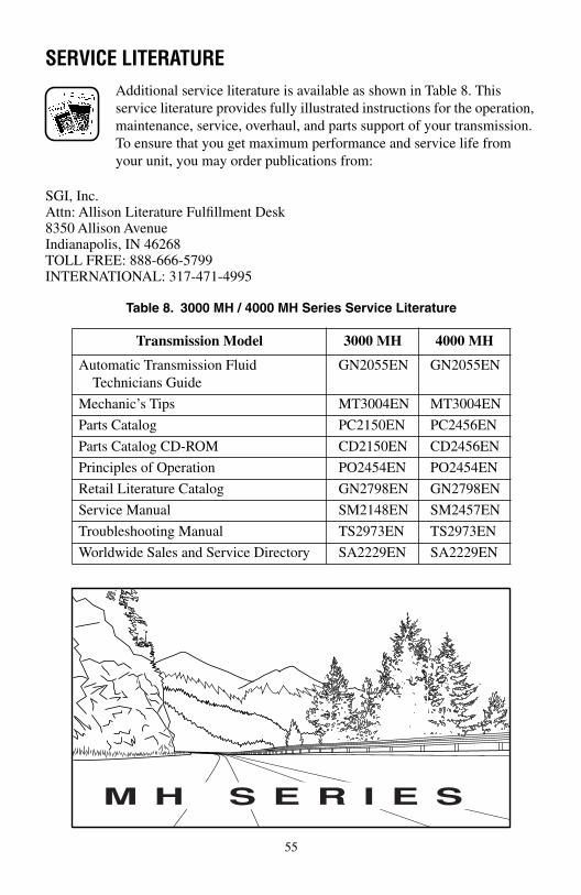
SERVICE LITERATUREAdditional service literature is available as shown in Table 8. This service literature provides fully illustrated instructions for the operation, maintenance, service, overhaul, and parts support of your transmission. To ensure that you get maximum performance and service life from your unit, you may order publications from:
SGI, Inc.Attn: Allison Literature Fulfillment Desk8350 Allison AvenueIndianapolis, IN 46268TOLL FREE: 888-666-5799INTERNATIONAL: 317-471-4995
Table 8. 3000 MH / 4000 MH Series Service Literature
Transmission Model 3000 MH 4000 MH
Automatic Transmission Fluid Technicians Guide
GN2055EN GN2055EN
Mechanic’s Tips MT3004EN MT3004EN
Parts Catalog PC2150EN PC2456EN
Parts Catalog CD-ROM CD2150EN CD2456EN
Principles of Operation PO2454EN PO2454EN
Retail Literature Catalog GN2798EN GN2798EN
Service Manual SM2148EN SM2457EN
Troubleshooting Manual TS2973EN TS2973EN
Worldwide Sales and Service Directory SA2229EN SA2229EN
M H S E R I E S
55

ALLISON TRANSMISSION DISTRIBUTORS
EASTERN REGION
Atlantic Detroit Diesel-Allison, LLC180 Route 17 SouthLodi, NJ 07644201-489-5800
Penn Detroit Diesel-Allison, Inc.8330 State RoadPhiladelphia, PA 19136-2986215-335-0500
Covington Detroit Diesel-Allison8015 Piedmont Triad ParkwayGreensboro, NC 27409336-292-9240
Western Branch Diesel, Inc.3504 Shipwright StreetPortsmouth, VA 23703757-484-6230
Johnson & Towers, Inc.2021 Briggs RoadMount Laurel, NJ 08054856-234-6990
Williams Detroit Diesel-Allison Southeast, Inc.2849 Moreland Avenue, S.E.Atlanta, GA 30315-0037404-366-1070
New England Detroit Diesel-Allison, Inc.90 Bay State RoadWakefield, MA 01880-1095781-246-1810
56
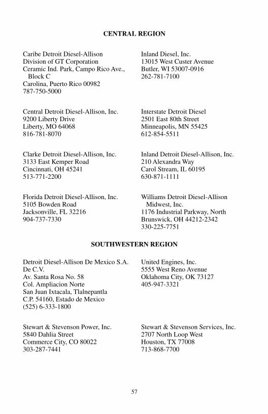
CENTRAL REGION
Caribe Detroit Diesel-AllisonDivision of GT CorporationCeramic Ind. Park, Campo Rico Ave., Block CCarolina, Puerto Rico 00982787-750-5000
Inland Diesel, Inc.13015 West Custer AvenueButler, WI 53007-0916262-781-7100
Central Detroit Diesel-Allison, Inc.9200 Liberty DriveLiberty, MO 64068816-781-8070
Interstate Detroit Diesel2501 East 80th StreetMinneapolis, MN 55425612-854-5511
Clarke Detroit Diesel-Allison, Inc.3133 East Kemper RoadCincinnati, OH 45241513-771-2200
Inland Detroit Diesel-Allison, Inc.210 Alexandra WayCarol Stream, IL 60195630-871-1111
Florida Detroit Diesel-Allison, Inc.5105 Bowden RoadJacksonville, FL 32216904-737-7330
Williams Detroit Diesel-Allison Midwest, Inc.1176 Industrial Parkway, NorthBrunswick, OH 44212-2342330-225-7751
SOUTHWESTERN REGION
Detroit Diesel-Allison De Mexico S.A. De C.V.Av. Santa Rosa No. 58Col. Ampliacion NorteSan Juan Ixtacala, TlalnepantlaC.P. 54160, Estado de Mexico(525) 6-333-1800
United Engines, Inc.5555 West Reno AvenueOklahoma City, OK 73127405-947-3321
Stewart & Stevenson Power, Inc.5840 Dahlia StreetCommerce City, CO 80022303-287-7441
Stewart & Stevenson Services, Inc.2707 North Loop WestHouston, TX 77008713-868-7700
57

WESTERN REGION
Pacific Detroit Diesel-Allison Company7215 South 228th StreetKent, WA 98032253-854-0505
Valley Detroit Diesel-Allison, Inc.425 South Hacienda BoulevardCity of Industry, CA 91745-1123626-333-1243
Sierra Detroit Diesel-Allison, Inc.1755 Adams AvenueSan Leandro, CA 94577-1001510-635-8991
Williams Detroit Diesel-Allison Southwest, Inc.2602 S. 19th AvenuePhoenix, AZ 85009602-257-0561
Smith Detroit Diesel-Allison, Inc.250 West 3900 SouthSalt Lake City, UT 84107801-262-2631
CANADIAN REGION
Detroit Diesel-Allison British Columbia Ltd.9300 - 192nd StreetSurrey, British Columbia V4N 3R8604-888-1211
Midwest Detroit Diesel-Allison Ltd.1460 Waverley StreetWinnipeg, Manitoba R3T OP6204-452-8244
Detroit Diesel-Allison Canada East(Div. of Integrated Power Systems Corp.)2997 Rue WattSte. Foy, Quebec G1X 3W1418-651-5371
Waterous Detroit Diesel-Allison (Div. of Integrated Power Systems Corp)10025 - 51 AvenueEdmonton, Alberta T6E OA8780-437-3550
Harper Detroit Diesel Ltd.10 Diesel DriveToronto, Ontario M8W 2T8416-259-3281
58

ALLISON TRANSMISSION REGIONAL OFFICES
EASTERN REGION
19 Oaklynn DriveP. O. Box 400Columbus, NJ 08022-0400609-298-2541
WESTERN REGION
39465 Paseo Padre ParkwaySuite 2400Fremont, CA 94538510-498-5208
CENTRAL REGION
P. O. Box 894, Speed Code PF06Indianapolis, IN 46206317-242-2327
CANADIAN REGION
P. O. Box 5160, Station ALondon, Ontario N6A 4N5519-452-5256
SOUTHWESTERN REGION
39465 Paseo Padre ParkwaySuite 2400Fremont, CA 94538510-498-5208
59

OM3349EN 200003 Printed in U.S.A. 200003
ATD 5376 Op Manual 5/15/00 11:28 AM Page 2