Operator’s Manual · 2017-10-11 · Operator’s Manual Part No. OME0502-15 Printed in U.S.A. The...
94
Operator’s Manual
Transcript of Operator’s Manual · 2017-10-11 · Operator’s Manual Part No. OME0502-15 Printed in U.S.A. The...

Operator’s ManualPart No. OME0502-15 Printed in U.S.A.
The first production inboard equipped with catalytic converters.
Ken Cook Co.
5400 Old Millington Road Millington, TN 38053
www.indmar.com
OME0502-15 Cover.qxp_OM0502-05 Cover.qxd 4/28/14 10:27 AM Page 1

PROPOSITION 65
The engine exhaust from this product contains chemicals known to the State of California to cause cancer, birthdefects or other reproductive harm.
WARNING
Date of Purchase: ______________________ Owner Name: _____________________________________________
Address: __________________________________________________ City: ________________________________
State/Province: ___________________________ Zip/Postal Code:____________ Country: ____________________
Engine Serial Number: _____________________________ Transmission Serial Number:_______________________
10-20 Hour ServiceDate:___________ Hours:____________By:_______________________________
Every 50 (25) Hour ServiceDate:___________ Hours:____________By:_______________________________
Date:___________ Hours:____________By:_______________________________
Date:___________ Hours:____________By:_______________________________
Date:___________ Hours:____________By:_______________________________
Date:___________ Hours:____________By:_______________________________
Date:___________ Hours:____________By:_______________________________
Date:___________ Hours:____________By:_______________________________
Date:___________ Hours:____________By:_______________________________
Every 100 Hour ServiceDate:___________ Hours:____________By:_______________________________
Date:___________ Hours:____________By:_______________________________
Date:___________ Hours:____________By:_______________________________
Date:___________ Hours:____________By:_______________________________
Date:___________ Hours:____________By:_______________________________
Date:___________ Hours:____________By:_______________________________
Date:___________ Hours:____________By:_______________________________
Date:___________ Hours:____________By:_______________________________
Date:___________ Hours:____________By:_______________________________
Every 300 Hour/Annual ServiceDate:___________ Hours:____________By:_______________________________
Date:___________ Hours:____________By:_______________________________
Date:___________ Hours:____________By:_______________________________
Date:___________ Hours:____________By:_______________________________
Date:___________ Hours:____________By:_______________________________
Date:___________ Hours:____________By:_______________________________
Every 2 Year ServiceDate:___________ Hours:____________By:_______________________________
Date:___________ Hours:____________By:_______________________________
Date:___________ Hours:____________By:_______________________________
OME0502-15 Cover.qxp_OM0502-05 Cover.qxd 4/28/14 10:27 AM Page 2

Indmar Marine Engines i
Throughout this manual, specific precautions and sym-bols identify safety related information.
The Safety Alert Symbol means ATTENTION!BECOME ALERT! YOUR SAFETY IS INVOLVED!
Indicates the presence of a hazard whichWILL cause SEVERE injury, death or sub-stantial property damage.
Indicates the presence of a hazard whichCAN cause SEVERE injury, death or substan-tial property damage.
Indicates the presence of a hazard whichWILL or CAN cause MINOR or MODERATEpersonal injury or property damage.
NOTICEIndicates installation, operation or maintenance infor-mation which is important but not hazard-related.
The precautions listed in this manual and on the engineor boat are not all-inclusive. If a procedure, method, toolor part is not specifically recommended, you must satisfyyourself that it is safe for you and others, and that theengine or boat will not be damaged or made unsafe as aresult of your decision.
! !
IMPORTANT SAFETY INFORMATION
!
OME0502-15 Body.qxp_OM0502-05 Body.qxd 5/20/14 12:45 PM Page i

ii Indmar Marine Engines
AxisMB SportsMalibuMoombaSangerSupraSvfaraTigé
The above list is subject to change as new customers become members of the Indmar family.
Engine Families:5.7L Electronic Fuel Injected6.0L Electronic Fuel Injected – L966.2L Electronic Fuel Injected – LS3, LSA
ENGINES COVERED
The information in this manual applies to the following Indmar-branded GM-based engines, as well as the GM-based engines built specifically for our OEM Boat Builder Customers listed below:
OME0502-15 Body.qxp_OM0502-05 Body.qxd 5/20/14 12:45 PM Page ii

Indmar Marine Engines iii
Dear Indmar Marine Engine Owner,
Thank you for selecting a boat powered by an Indmar Marine Engine. Indmar is proud to provide the powerto the best boat companies in the business and we hope that pride shows in the quality of our products. Inthe unlikely event that you have a defect related problem with your boat’s engine / drive train, you canrest assured knowing it is backed by our industry leading Factory 3 standard 3-year warranty coverage.
This is another exciting year for Indmar and for the marine industry. Indmar has expanded its line ofmarine inboard engines equipped with catalytic converters. Indmar’s ETX/CAT system reduces exhaust emis-sions, including carbon monoxide (CO), to provide a cleaner and safer boating experience for you and yourfamily. ETX/CAT is standard on all 5.7L, 6.0L and 6.2L naturally aspirated Electronic Fuel Injected (EFI)engines built for sale in the U.S. and Canada.
If you have any questions concerning your engine that are not covered in this manual, please feel welcometo contact Indmar Customer Service at (901) 353-9930 or visit our website, www.indmar.com, and submityour question.
Thanks again for choosing an Indmar powered boat. We wish you safe, trouble-free boating.
Sincerely,
Team Indmar
WELCOME
OME0502-15 Body.qxp_OM0502-05 Body.qxd 5/20/14 12:45 PM Page iii

iv Indmar Marine Engines
INDMAR MARINE ENGINES COMPANY MISSION
To produce the world’s finest, most advanced and most dependable gasoline inboard marine engines at the best possible price,
while respecting the needs of our employees, customers, vendors and the precious environment we share.
OME0502-15 Body.qxp_OM0502-05 Body.qxd 5/20/14 12:45 PM Page iv

Indmar Marine Engines v
Introduction . . . . . . . . . . . . . . . . . . . . . . . . . . . . . . . . . . . . . . . . . . . . viiChapter 1: First Time Operation and Break-In . . . . . . . . . . . . . . . 1-1 First Time Operation . . . . . . . . . . . . . . . . . . . . . . . . . . . . . . . . . .1-1Chapter 2: General Operations and Warnings . . . . . . . . . . . . . . . 2-1Chapter 3: Engine Starting Procedures . . . . . . . . . . . . . . . . . . . . . 3-1 How to Start Your Engine . . . . . . . . . . . . . . . . . . . . . . . . . . . . . .3-2 If Engine Does Not Start . . . . . . . . . . . . . . . . . . . . . . . . . . . . . .3-3 How to Clear the Engine . . . . . . . . . . . . . . . . . . . . . . . . . . . . . .3-3 Engine Restart . . . . . . . . . . . . . . . . . . . . . . . . . . . . . . . . . . . . . .3-4Chapter 4: Normal Operation . . . . . . . . . . . . . . . . . . . . . . . . . . . . . 4-1 Sensible Operation . . . . . . . . . . . . . . . . . . . . . . . . . . . . . . . . . . .4-1 Daily Routine . . . . . . . . . . . . . . . . . . . . . . . . . . . . . . . . . . . . . . . .4-1 Operating the Controls . . . . . . . . . . . . . . . . . . . . . . . . . . . . . . . .4-3 Unusual Vibration . . . . . . . . . . . . . . . . . . . . . . . . . . . . . . . . . . . .4-4 Fuel System . . . . . . . . . . . . . . . . . . . . . . . . . . . . . . . . . . . . . . . .4-4 Battery . . . . . . . . . . . . . . . . . . . . . . . . . . . . . . . . . . . . . . . . . . . . .4-4 “Service Required” or “Check Engine” Indicator (EFI Engines Only) . . . . . . . . . . . . . . . . . . . . . . . . . . . . . . . . .4-5 Check Transmission Light . . . . . . . . . . . . . . . . . . . . . . . . . . . . .4-6 Engine Cooling . . . . . . . . . . . . . . . . . . . . . . . . . . . . . . . . . . . . . .4-6 Exhaust Hoses . . . . . . . . . . . . . . . . . . . . . . . . . . . . . . . . . . . . . .4-8
TABLE OF CONTENTS
OME0502-15 Body.qxp_OM0502-05 Body.qxd 5/20/14 12:45 PM Page v

vi Indmar Marine Engines
Selecting a Propeller . . . . . . . . . . . . . . . . . . . . . . . . . . . . . . . . .4-8Chapter 5: Fuel . . . . . . . . . . . . . . . . . . . . . . . . . . . . . . . . . . . . . . . . 5-1 What Type of Gasoline to Use . . . . . . . . . . . . . . . . . . . . . . . . . .5-1 Using Oxygenated Fuels or Fuels with Alcohol . . . . . . . . . . . .5-2 Fuels in Other Countries . . . . . . . . . . . . . . . . . . . . . . . . . . . . . .5-2Chapter 6: Maintenance . . . . . . . . . . . . . . . . . . . . . . . . . . . . . . . . . 6-1 General Service Notes . . . . . . . . . . . . . . . . . . . . . . . . . . . . . . . .6-1 Engine Oil . . . . . . . . . . . . . . . . . . . . . . . . . . . . . . . . . . . . . . . . . .6-4 Engine Flame Arrestor . . . . . . . . . . . . . . . . . . . . . . . . . . . . . . . .6-8 Engine Cooling . . . . . . . . . . . . . . . . . . . . . . . . . . . . . . . . . . . . . .6-8 Internal (Cooling System) Care . . . . . . . . . . . . . . . . . . . . . . . .6-12 Fuel System . . . . . . . . . . . . . . . . . . . . . . . . . . . . . . . . . . . . . . .6-14 Transmissions . . . . . . . . . . . . . . . . . . . . . . . . . . . . . . . . . . . . . .6-14 Electrical System . . . . . . . . . . . . . . . . . . . . . . . . . . . . . . . . . . .6-19 Wiring . . . . . . . . . . . . . . . . . . . . . . . . . . . . . . . . . . . . . . . . . . . .6-20Chapter 7: Storage and Winter Lay-up . . . . . . . . . . . . . . . . . . . . . 7-1 General Preparation . . . . . . . . . . . . . . . . . . . . . . . . . . . . . . . . . .7-2 Reactivating Engine After Extended Storage . . . . . . . . . . . . .7-10 Extended Storage . . . . . . . . . . . . . . . . . . . . . . . . . . . . . . . . . . .7-12Chapter 8: Troubleshooting . . . . . . . . . . . . . . . . . . . . . . . . . . . . . . 8-1Appendix A – Maintenance Components and Fluids . . . . . . . . . .A-1Appendix B – Engine Specifications . . . . . . . . . . . . . . . . . . . . . . . B-1Appendix C – Limited Warranty . . . . . . . . . . . . . . . . . . . . . . . . . . C-1
OME0502-15 Body.qxp_OM0502-05 Body.qxd 5/20/14 12:45 PM Page vi

This manual will acquaint you with basic informationneeded to safely operate and maintain your Indmarengine. We suggest you and all other operators read theentire manual before using your boat.
We recommend you contact your Indmar dealer for allengine service. Certified Indmar Technicians are trained.They have current specifications, parts and the specialequipment needed to service your Indmar engine anddrive line. To find your nearest Indmar dealer, please call(901) 353-9930 or visit our website at www.indmar.com.
To ensure that the proper information is available, notethe six digit engine serial number. Your dealer shouldhave written the engine serial number on the inside backcover of this manual. The serial number is stamped onthe engine block; see Figure 1.1 for locations. The serialnumber also appears on the emissions label at the rearof the engine and on several stick-on tags that areattached to major engine components.
Figure 1.1 – Serial Number Locations
INDM-A001
EMISSIONSLABEL
INTRODUCTION
Indmar Marine Engines vii
OME0502-15 Body.qxp_OM0502-05 Body.qxd 5/20/14 12:45 PM Page vii
viii Indmar Marine Engines
Warranty Registration
The Federal Boat Safety Act of 1971 requires registra-tions of marine products sold in the United States bemaintained by the manufacturer and dealers of thoseproducts. Your dealer should have completed your warranty registration to comply with federal regulations.This registration enables us to contact you, if it shouldbecome necessary, to change or improve your product.The engine serial number is stamped into the block and should also be written on the inside of the backcover of this manual. Always retain a copy of the serialnumber for your personal records.
OME0502-15 Body.qxp_OM0502-05 Body.qxd 5/20/14 12:45 PM Page viii

Indmar Marine Engines ix
Warranty Registration Transfer
The remainder of the engine warranty is transferable to asecond or subsequent owner. Warranty transfers mustbe completed within 10 days of the transfer of owner-ship.
If the trade-in and resale is handled by an authorizedIndmar dealer, the dealer must fill out the warranty regis-tration transfer form and send it and other paperworkspecified along with the warranty transfer fee (currently$200.00) and the transfer will be processed on approvalby Indmar.
If the sale of the boat is from a private owner to anotherindividual, the engine package must be inspected, at theseller or purchaser’s expense, and the Inspection Form,Warranty Transfer Form, specified paperwork and trans-fer fee (currently $200.00) and the transfer will beprocessed on approval by Indmar.
The new boat owner will be notified within 10 days ofIndmar’s receipt of the transfer paperwork whether thetransfer has been accepted or not. If the transfer hasbeen accepted, the warranty expiration date will also beprovided for the new owner.
To obtain enjoyment from your boat, follow recommenda-tions described in this manual. The knowledge you gainthrough careful review will help you experience lastingsatisfaction.
Further information regarding the care, operation,required equipment or specifications for your boat can beobtained from your local US Coast Guard Auxiliary, USPower Squadron, state boating authorities, or theAmerican Red Cross. Know the law and your responsi-bilities as a boat owner.
Any alteration, change, improper maintenance or abnor-mal use by you which renders the engine or any of itscomponents unreasonably dangerous will void all war-ranties and Indmar will not be liable for the resultingdamages or injuries.
OME0502-15 Body.qxp_OM0502-05 Body.qxd 5/20/14 12:45 PM Page ix

x Indmar Marine Engines
EMISSION CONTROL WARRANTY INFORMATION
The inboard engine in your boat includes the IndmarEmission Control Systemidentified as MFI. The fueland ignition systems onyour engine meet the stringent requirements setforth by the U.S.Environmental ProtectionAgency (EPA) and theCalifornia Air ResourcesBoard (CARB). Indmaralso uses propylene glycolanti-freeze in the closedcooling system of yourengine to reduce the environmental impact inthe event that anti-freeze is expelled from theengine.
Your Indmar manufactured engine has a special environ-mental label required by the California Air ResourcesBoard (CARB). The label has 1, 2, 3 or 4 stars. A hang-tag, provided with your inboard engine, describes themeaning of the star system.
Operating Fuels and Lubricants
In order to keep your engine operating efficiently and tomaintain the Emission Control System the followingrequirements must be observed.
Fuel – Your engine was designed and certified tooperate on the unleaded fuels listed below. Fuel rat-ings must be based on the (R+M)/2 method and meetthe specifications ASTM D4814 in the US. Thesefuels need no additives for proper operation.
• LS3 and LSA Engines 91 Octane • All other Indmar Engines 89 Octane
INDM-A041
INDM-A042
OME0502-15 Body.qxp_OM0502-05 Body.qxd 5/20/14 1:13 PM Page x

Indmar Marine Engines xi
Lubricant – Indmar uses and recommends 15W40Marine Oil for use in all of its engines except forthe LS series engines which use Mobil 1 5W30 oil.If marine oil is not available, any appropriate viscosity motor oil meeting the API ratings of SL,CI-4 is acceptable. See Chapter 6, Maintenance,for information regarding the use of synthetic oil.Additives – The only additive that is recommended byIndmar for use in your engine is Sta-Bil brand fuel sta-bilizer. This additive helps preserve the fuel in yourtank and in the engine’s fuel system. We recommendthe use of Marine Formula Sta-Bil during off-seasonstorage and for the boater that consumes less than afull tank of fuel every two weeks. See Chapter 5, Fuel,for more information.
EPA Emission-Related Warranty RequirementsYour new engine is designed, built, and equipped so itconforms at the time of sale to the ultimate purchaserwith the requirements of CFR 40, part 1045.120. It is freefrom defects in materials and workmanship that maykeep it from meeting these requirements.
The minimum emission-related warranty period is 3 years/480 hours, whichever comes first. The emission-related warranty covers all components whose failurewould increase an engine’s emissions of any regulatedpollutant, including components listed below and compo-nents from any other system developed to control emissions.
Emissions Components WarrantyThe following components are considered as part of theemissions control system and are covered under theEmissions Control Warranty.1. Fuel Metering System
A. Fuel injectorsB. Fuel pressure regulatorC. Manifold Absolute Pressure SensorD. Throttle Position SensorE. Idle Air Control ValveF. Throttle Body – Port Fuel Injection ModelsG. Throttle Body Assembly – Throttle Body Fuel Injection ModelsH. CarburetorI. Coolant Temperature SensorJ. Intake ValvesK. Oxygen Sensors
2. Air Induction SystemA. Intake ManifoldB. Air Filter (Flame Arrestor)
3. Ignition SystemA. Spark PlugsB. Electronic Ignition SystemC. Ignition coil and/or control moduleD. Ignition Wires
4. Lubrication SystemA. Oil pump and internal parts
5. Positive Crankcase Ventilation (PCV) SystemA. PCV valveB. Oil Filler Cap
OME0502-15 Body.qxp_OM0502-05 Body.qxd 5/29/14 1:43 PM Page xi

xii Indmar Marine Engines
6. Exhaust SystemA. Exhaust manifold(s)B. Exhaust riser(s)C. Exhaust valvesD. Catalytic Converters
7. Miscellaneous Items Used on Above SystemsA. Hoses, clamps, fittings, tubing, sealing gaskets or devices and mounting hardwareB. Electronic ControlsC. Electronic Control ModuleD. Pulleys, belts and idlers
NOTICEThe repair or replacement of any warranted part oth-erwise eligible for warranty coverage under theEmission Control Warranty may be excluded fromsuch warranty coverage if Indmar demonstrates thatthe engine has been abused, neglected, or improperlymaintained and that such abuse neglect or impropermaintenance was the direct cause of the need forrepair or replacement of the part.
The emission warranty covers damage to other enginecomponents that is caused by the failure of a warrantedpart.
This manual contains written instructions for the propermaintenance and use of your inboard engine. All emis-sion warranty parts are warranted by Indmar for theentire warranty period of the engine, unless the part isscheduled for replacement as required maintenance inthe Operator’s Manual.
Emission warranty parts that are scheduled for replace-ment, as required maintenance, are warranted by Indmarfor the period of time before the first scheduled replace-ment date for that part. Emission warranted parts thatare scheduled for regular inspection, but not regularreplacement, are warranted by Indmar for the entire warranty period of the inboard engine.
Any emission warranty part repaired or replaced underthe terms of this warranty statement is warranted byIndmar for the remainder of the warranty period of theoriginal part. All parts replaced under this limited warrantybecome the property of Indmar.
If the ownership of a product is transferred duringEmission Components Warranty period, this warrantyshall also be transferred and be valid for the remainingcoverage period provided that Indmar is notified in thefollowing way:
a. The former owner contacts Indmar and provides uswith the required information listed below; or
OME0502-15 Body.qxp_OM0502-05 Body.qxd 5/29/14 1:43 PM Page xii

Indmar Marine Engines xiii
b. Indmar receives a proof that the former owner agreedto the transfer of ownership and we are provided withthe information listed below.
- Current owner’s name, address, telephone, engine serial number and date of purchase
- New owner’s name, address, telephone, engine serial number and date of transfer
Send the above information to:
Indmar Products5400 Old Millington RdMillington, TN 38053Attn: Emission Warranty Transfer
NOTICEThe above procedure is valid for the transfer of theEmission Components warranty only. Refer to theLimited Warranty in Section C of this manual for informa-tion regarding warranty transfer of the remaining enginecomponents.
Emission Maintenance Requirements
The following component maintenance is required tomaintain the Emission Control System of your engine.See Chapter 6, Maintenance, for procedures.
• Engine oil and filter: Change oil and filter after the first10 hours then every 50 hours or annually, whicheveroccurs first.
• Flame Arrestor: Clean every 100 hours. Replace asnecessary.
• Spark Plugs: Replace every 300 hours or annually,whichever occurs first.
• Fuel Injectors: Clean every 300 hours or annually,whichever occurs first.
• PCV Valve: Inspect annually. Replace as necessary.• Spark Plug Wires: Inspect annually. Replace as
necessary.
NOTICEIgnition timing, engine idle speed and air-fuel mixtureare not adjustable on this engine. NO OTHERADJUSTMENTS NEEDED.
OME0502-15 Body.qxp_OM0502-05 Body.qxd 5/29/14 1:43 PM Page xiii
xiv Indmar Marine Engines
Engine Model Engine Oil
Oil Filter
SparkPlugs
PCV Valve
OxygenSensor
FlameArrestor
Plug Wires
Dist Cap Dist Rotor
5.7L Electronic Fuel InjectedNon Catalyst ModelsCatalyst Models 871001
15W40
501001PZ52
556199 505001
556162
521119525028525022525011
756004 Red751104 Blue
556345 556346
6.0L Electronic Fuel InjectedL96 Models
501018PZ167
556188 N/A 525021751203
N/A N/A6.2L Electronic Fuel Injected 8710035W30
Mobil 1LS3 ModelsLSA Models N/A 751202
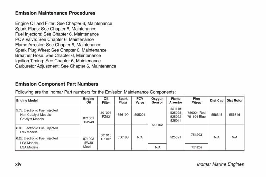
Emission Component Part Numbers
Following are the Indmar Part numbers for the Emission Maintenance Components:
Emission Maintenance Procedures
Engine Oil and Filter: See Chapter 6, MaintenanceSpark Plugs: See Chapter 6, MaintenanceFuel Injectors: See Chapter 6, MaintenancePCV Valve: See Chapter 6, MaintenanceFlame Arrestor: See Chapter 6, MaintenanceSpark Plug Wires: See Chapter 6, MaintenanceBreather Hose: See Chapter 6, MaintenanceIgnition Timing: See Chapter 6, MaintenanceCarburetor Adjustment: See Chapter 6, Maintenance
OME0502-15 Body.qxp_OM0502-05 Body.qxd 5/29/14 1:43 PM Page xiv

Indmar Marine Engines xv
CALIFORNIA EMISSION CONTROLWARRANTY STATEMENTYOUR WARRANTY RIGHTS AND OBLIGATIONS
The California Air Resources Board and Indmar Productsare pleased to explain the emission control system warranty on your inboard engine. In California, newinboard engines must be designed, built and equipped to meet the State’s stringent anti-smog standards.Indmar Products must warrant the emission control system in your inboard engine for the time listed belowprovided there has been no abuse, neglect or impropermaintenance of your inboard engine.
Your emission control system may include parts such asthe carburetor or fuel injection system, the ignition system, and catalytic converter. Also included may behoses, belts, connectors and other emission-relatedassemblies.
Where a warrantable condition exists, Indmar Productswill repair your inboard engine at no cost to you, including diagnosis, parts and labor.
Manufacturer’s Warranty Coverage
Select emission control parts from model year 2009 andlater are warranted for 3 years.
OME0502-15 Body.qxp_OM0502-05 Body.qxd 5/20/14 12:45 PM Page xv
xvi Indmar Marine Engines
Owner’s Warranty Responsibilities
As the inboard engine owner, you are responsible for theperformance of the required maintenance listed in yourowner’s manual. Indmar Products recommends that youretain all receipts covering maintenance on your inboardengine, but Indmar Products cannot deny warranty solelyfor the lack of receipts or your failure to ensure the per-formance of all scheduled maintenance.
As the inboard engine owner, you should be aware thatIndmar Products may deny you warranty coverage ifyour inboard engine or part has failed due to abuse, neg-lect, improper maintenance or unapproved modifications.The most common failures we see are due to unstableor old fuel and lack of proper lubrication. Failures that areattributed to old/unstable fuel or lack of lubrication arenot warrantable.
If your engine is operated in salt or brackish water, spe-cial precautions, such as flushing the engine internallyand externally, are important. See the “Salt WaterOperation” information in Chapter 6. Failures due to corrosion are not covered by the Indmar LimitedWarranty.
You are responsible for presenting your inboard engineto an Indmar Products service center as soon as a problem exists. The warranty repairs should be completed in a reasonable amount of time, generallywithin 30 days.
If you have any questions regarding your warranty rightsand responsibilities, you should contact IndmarCustomer Service at 1-901-353-9930.
OME0502-15 Body.qxp_OM0502-05 Body.qxd 5/20/14 12:45 PM Page xvi
Indmar Marine Engines 1-1
A new engine may use a more than normalamount of engine oil before it is broken in.Check your oil level hourly during the break-inperiod. Once the engine is broken in, checkthe oil level before each day’s use and moreoften during sustained periods of high RPM orheavily loaded operation. Marine usage is different from automobile usage and oil consumption is EXPECTED. Do not be alarmedif you have to add oil between oil changes.
The following checks assumes your dealer has per-formed the pre-delivery service and inspection. Completethe following pre-start check list before starting yourengine for the first time. If you have questions about anyof these procedures, see your Indmar dealer for assis-tance.
FIRST TIME OPERATION1. Check the boat hull and/or garboard drain plug. Make
sure they are installed and secure. Check the boatowner’s manual for additional pre-operation checks.
2. Make sure all engine drain plugs are installed. Referto Chapter 7, Storage and Winter Layup. There areseveral drain locations: Block – There are block drain points on both sides ofthe engine. Some engines have brass drain plugs oneach side and some engines have knock sensorsinstalled in the block drain holes (Figure 1.2).
NOTICEOn the 6.0 and 6.2 Liter engines, removing the knocksensor does NOT drain the block. Remove the capsfrom the brass fittings on both sides of the engine todrain water from the block.
Exhaust – The drain hose must be connected. Transmission – The transmission oil cooler has onedrain plug. In addition, the Walters V-Drive and ZFSki-Vee (if equipped) have two drain plugs. SeeChapter 7 for instructions.
Chapter 1 FIRST TIME OPERATION AND BREAK-IN
OME0502-15 Body.qxp_OM0502-05 Body.qxd 5/20/14 12:45 PM Page 1-1

1-2 Indmar Marine Engines
Fresh Water Cooling System – If equipped, the heatexchanger has four drain plugs; two for raw water andtwo for coolant. Refer to Chapter 7, Storage andWinter Lay-up.
Figure 1.2 – Anti Knock Sensor
3. Make sure your battery is fully charged and thecables are clean and tight.
4. Check engine oil for correct level. Refer to Chapter 6,Maintenance.
Figure 1.3 – Engine Dipstick Level
5. Check transmission oil level for correct level. Refer toChapter 6, Maintenance.
6. If your engine is equipped with fresh water cooling,check the expansion tank for the correct level. Referto Chapter 6, Maintenance.
Do not mix antifreeze types.
7. Inspect engine mounts to make sure they aligned andtight. Make sure that the propeller shaft coupler boltsare tight.
Make sure the engine water intake is notblocked by the trailer bunk. Blocked orrestricted water flow may damage the engine.
IND-A005A
1
ADDOPERATING RANGE SEE OWNERS MANUA
INDM-A003
OME0502-15 Body.qxp_OM0502-05 Body.qxd 5/20/14 12:45 PM Page 1-2

Indmar Marine Engines 1-3
8. Back trailer into the water. Make sure the enginewater intake is submerged.
Before starting engine operate bilge blowerat least 4 minutes and raise engine cover toventilate fumes. Inspect engine and compart-ment for any fluid or fuel leaks. Failure to doso can possibly result in fire and/or explo-sion resulting in death or serious injury toyou and your passengers.
Figure 1.4 – Raised Engine Cover
NOTICEPriming the EFI Fuel Systemis required before startingyour EFI engine for the firsttime. This allows the electricfuel pump to fill the fuel injec-tion lines with gasoline. Eachtime you advance the ignitionswitch to the “ON” position,the fuel pump cycles for 2seconds.
9. Prime the fuel system bycycling the fuel pump eightto ten times before theengine is started for the firsttime. To prime:• Turn the ignition key ON
for 5 seconds. • Turn the ignition key OFF for 5 seconds. • Repeat above eight to ten times
NOTICEThe above procedure is only necessary for the firsttime the engine is started or in the event the fuel tankis run dry.
! !
ON
STARTOFF
ACC
INDM-A006
Figure 1.5 – Engine“On” Switch
OME0502-15 Body.qxp_OM0502-05 Body.qxd 5/20/14 12:45 PM Page 1-3

1-4 Indmar Marine Engines
10. Start the engine (Refer to Chapter 2, GeneralOperation and Warnings) and allow it to reach nor-mal operating temperature; keep a close eye on thegauges. If any of the gauges indicate an engineproblem, stop the engine immediately and bring theboat to your Indmar dealer for assistance.
Do not operate starter motor for more than15 seconds without a 2 (two) minute cool-down period. Excessively long crankingtimes will permanently damage the startermotor and drain the battery.
Break-In
Taking care now to break-in your new Indmar engine isVERY important. When properly broken in, your enginewill last longer, run better and require fewer repairs overits lifetime. Your new Indmar engine does not require anelaborate break-in procedure, just a little care and com-mon sense for the first 10 hours.
Break-in Tips
• Always let engine warm up to normal operating tem-perature before accelerating.
• Avoid fast accelerations and don’t carry (or pull) aheavy load during this period.
• If your boat is equipped with ballast tanks, do not usethem during the first 10 hours.
• Check engine and transmission fluid levels frequently.During the first 50 to 100 hours, an engine can usemore oil than usual. Maintain oil at proper levels at alltimes but do not overfill.
• Vary your boat speed during break-in. Do not run atthe same speed very long.
• Observe gauge readings and check for loose mount-ings, fittings, nuts, bolts and clamps.
• Report abnormal operation, noises or vibrations toyour dealer.
Break-in Steps
1. For the first hour, do not exceed 2000 RPM; varyRPM continuously.
2. For the second hour, do not exceed 3000 RPM; varythe RPM regularly.
3. For the next seven hours, do not exceed 4000 RPM;vary the RPM regularly.
OME0502-15 Body.qxp_OM0502-05 Body.qxd 5/20/14 12:45 PM Page 1-4

Indmar Marine Engines 1-5
After the first ten hours but before 20 hours of operation,take your boat to the dealer for its first engine and trans-mission oil and filter change and engine checkup. YourIndmar dealer is best equipped to check the engineimmediately after break-in.
After the break-in procedure is over, your boat may beoperated at any speed. Be sure to check the wide openthrottle operating range; refer to Chapter 4, Selecting APropeller.
Do not exceed maximum RPM recommendedfor your engine. Exceeding the maximumRPM may result in damage to the engine.
OME0502-15 Body.qxp_OM0502-05 Body.qxd 5/20/14 12:45 PM Page 1-5
1-6 Indmar Marine Engines
OME0502-15 Body.qxp_OM0502-05 Body.qxd 5/20/14 12:45 PM Page 1-6

Indmar Marine Engines 2-1
The engine exhaust from this product con-tains chemicals known to the State ofCalifornia to cause cancer, birth defects orother reproductive harm.
Operating a boat is a safe and enjoyable experience.
Indmar marine engines use gasoline for fuel. The areaunder the engine and around the gasoline tank and sup-ply lines is not open to outside air. Ventilation aroundthese areas must be provided by your bilge blower sys-tem and air vents located around the boat. We recom-mend taking time out to carefully inspect your boat atleast once a day for gasoline fumes, oil leaks, and areaswhere wiring may be worn or damaged.
Explosive gasoline and battery fumes mayaccumulate in your engine compartment.Failure to properly ventilate fumes with thebilge blower may result in explosive atmos-phere resulting in death or serious injury toyou and your passengers.
Before starting engine operate bilge blowerat least 4 minutes and raise engine cover toventilate fumes. Inspect engine and compart-ment for any fluid or fuel leaks.Failure to doso can possibly result in fire and/or explo-sion resulting in death or serious injury toyou and your passengers.
! !
Chapter 2GENERAL OPERATION AND WARNINGS
OME0502-15 Body.qxp_OM0502-05 Body.qxd 5/20/14 12:45 PM Page 2-1
2-2 Indmar Marine Engines
When refueling, make sure to open the motor box andrun the blower during and after the re-fueling operation.Failure to do so may result in fire or explosion and maycause death or serious injury.
Carbon monoxide gas (CO) is colorless,odorless and extremely dangerous. Allengines and fuel burning appliances produceCO as exhaust. Direct and prolonged expo-sure to CO will cause BRAIN DAMAGE orDEATH. Signs of exposure to CO includenausea, dizziness and drowsiness. Ensureadequate ventilation to prevent accumulationof CO in the boat.
Each year, boaters are injured or killed by carbonmonoxide. Virtually all of these injuries and deaths arepreventable. Carbon monoxide is a potentially deadlygas produced anytime a carbon-based fuel, such asgasoline, burns. Carbon monoxide sources on your boatinclude gasoline engines and generators, cookingranges, space heaters and water heaters.
Some Indmar engines are equipped with catalytic con-verters which significantly reduce harmful CO emissions,but it is important that all of the DO’s and DON’Ts stillbe followed.
Please follow these DOs and DON’Ts to ensure a safeboating experience every time.
DON’T swim or sit near the swim platform when anyengine is running.DON’T hold on to the swim platform while the boat isunderway (no “Teak Surfing”).DON’T moor next to another boat whose engine is running.DON’T confuse carbon monoxide poisoning with sea-sickness or intoxication.
DO immediately move the person to fresh air, investigatethe cause and take corrective action if someone onboard complains of irritated eyes, headache, nausea,weakness or dizziness. Seek medical attention if neces-sary.DO make sure generators are properly ventilated andkeep engine and generator exhausts clear.DO always shut off engine and generator when moored,anchored or standing still.DO be aware that the station wagon effect, or backdraft-ing, can cause carbon monoxide to accumulate insidethe cabin, cockpit and bilge when the boat is underway,moving at slow speed or idling.DO keep your boat’s engine well-maintained and regularlycheck to make sure carbon monoxide detectors in thecabin are working properly.DO always wear a properly fitted life jacket while in oraround water.
! !
OME0502-15 Body.qxp_OM0502-05 Body.qxd 5/20/14 12:45 PM Page 2-2

Indmar Marine Engines 2-3
For more information on carbon monoxide and boats,contact the US Coast Guard Office of Boating Safety at1-800-368-5647 or www.uscgboating.org or your stateboating law administrator at 1-800-225-9487 orwww.nasbla.org.
Never remove or modify any components ofthe engine’s fuel system. Tampering with fuelcomponents may cause a hazardous condi-tion that could result in severe personalinjury or death. This work must be performedby your Indmar dealer’s technicians.
Your Indmar Marine Engine is cooled bypumping water from the body of water thatthe engine is being operated in through theengine or through the heat exchanger onclosed cooled engines. Freezing tempera-tures will severely damage the engine block,cooling system components and exhaustsystem components. Contact your dealer orsee Chapter 7 for draining instructions.
Daily Pre-Start Checks
Refer to Chapter 6, Maintenance for checks and services.
Figure 2.1 – Pre-Start Check Points
1. Verify boat hull and/or garboard drain plug are inplace.
2. Carefully inspect engine compartment for signs offluid leakage and proper ventilation. Unlike autos,marine engine compartments require positive ventila-tion and air re-circulation to ensure that flammableand explosive vapors are safely dispersed in an envi-ronmentally sound manner.
INDM-A007
1312111098765432
15 14 161
1
OME0502-15 Body.qxp_OM0502-05 Body.qxd 5/20/14 12:45 PM Page 2-3

2-4 Indmar Marine Engines
3. Verify engine drain plugs are in place.4. Check engine oil level with the dipstick.
Figure 2.2 – Engine Oil Dipstick
5. Verify fuel lines are tight and there is no leakagepresent.
6. Inspect oil lines and oil filter. Ensure they are tightand no leakage is present.
Figure 2.3 – Engine Oil Filter
7. Check transmission fluid level. Check V-Drive fluidlevel if equipped.
8. If your engine is equipped with a fresh water coolingsystem, check coolant level in the expansion tank.
9. Check alternator belt for wear and proper tension.10. Verify that exhaust hoses are in good condition and
clamped tight.11. Ensure that the propeller shaft coupler bolts are tight.12. Verify engine mounts are tight.
INDM-B001INDM-A009
OME0502-15 Body.qxp_OM0502-05 Body.qxd 5/20/14 12:45 PM Page 2-4
Indmar Marine Engines 2-5
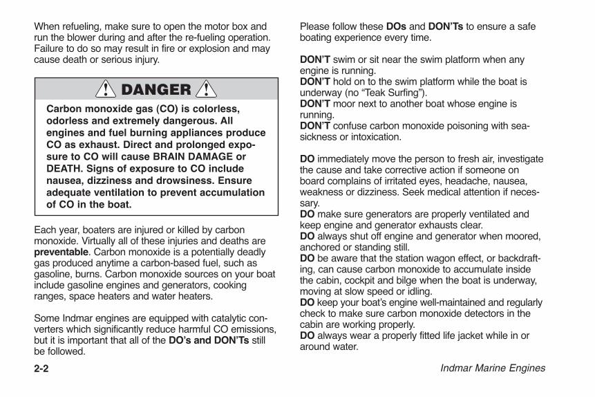
13. Check electrical connections and ensure connectorsare tight. Check wiring for signs of wear and abrasion.
14. Verify throttle/shift control is functional and properlyadjusted.
15. Verify steering controls are functional and properlyadjusted.
16. Verify battery connections are clean and securelyfastened.
Figure 2.4 – Battery Connections
INDM-A010
OME0502-15 Body.qxp_OM0502-05 Body.qxd 5/20/14 12:45 PM Page 2-5

2-6 Indmar Marine Engines
OME0502-15 Body.qxp_OM0502-05 Body.qxd 5/20/14 12:45 PM Page 2-6
Indmar Marine Engines 3-1
Explosive gasoline and battery fumes mayaccumulate in your engine compartment.Failure to properly ventilate fumes with thebilge blower may result in explosive atmos-phere resulting in death or serious injury toyou and your passengers.
Before starting engine operate bilge blowerat least 4 minutes and raise engine cover toventilate fumes. Inspect engine and compart-ment for any fluid or fuel leaks. Failure to doso can possibly result in fire and/or explo-sion resulting in death or serious injury toyou and your passengers.
When refueling, make sure to open the motor box andrun the blower during and after the re-fueling operation.Failure to do so may result in fire or explosion and maycause death or serious injury.
Never remove or modify any components ofthe engine’s fuel system. Tampering with fuelcomponents may cause a hazardous condi-tion that could result in severe personalinjury or death. This work must be performedby your Indmar dealer’s technicians.
NOTICECurrent fuel injected engines are equipped with a feature called “Smart Start.” When the key isadvanced to the START position, the starter willremain engaged and will crank the engine for 15 seconds or until the engine starts, whichever happensfirst. This same feature will prevent accidentalengagement of the starter when the engine is running.
! !
Chapter 3ENGINE STARTING PROCEDURES
OME0502-15 Body.qxp_OM0502-05 Body.qxd 5/20/14 12:45 PM Page 3-1

3-2 Indmar Marine Engines
HOW TO START YOUR ENGINE
1. Run the blower for 4 minutes to remove explosivegasoline and battery fumes from the engine compartment.
2. Perform the Daily Pre-Startchecks. Refer to Chapter 2,General Operation andWarnings.
3. Move the shift control lever tothe NEUTRAL position. Pullout the neutral safety lever (ifequipped). Without advancingthe throttle lever, turn thestarter key to START position.
NOTICEBecause of the electronic engine controls, there is noneed to advance the throttle to set an automaticchoke. The throttle should be in the neutral positionwith the neutral detent button on the shift control boxpulled out.
4. When the engine starts to crank, you can releasethe key and let SmartStart take over. When the engine starts, it willgradually slow from a fastidle to normal idle. If engine is cold, it willoperate at a slightly higher idle speed untilwarm-up is complete.Make sure that when youdo shift into gear that youare at idle speed (lessthan 1100 RPM). Letengine warm up to normal operating temperature beforeaccelerating.
Once the engine has started, immediatelycheck the oil pressure. Monitor the oil pressure and engine temperature closely forthe first 10 minutes of operation.
Figure 3.1 – TypicalBlower Switch Figure 3.2 – Start
Position
ONBLOWER
OFF
INDM-A011
ON
STARTOFF
ACC
INDM-A012
OME0502-15 Body.qxp_OM0502-05 Body.qxd 5/20/14 12:45 PM Page 3-2

Indmar Marine Engines 3-3
IF ENGINE DOES NOT START
Do not operate starter motor for more than15 seconds without a 2 (two) minute cool-down period. Excessively long crankingtimes will permanently damage the startermotor and drain the battery. Damage fromoverheating the starter motor is not coveredby the warranty.
Turn the key to the START position. If the engine doesnot start, let the starter cool down for two minutes, disengage the shift interlock and advance the throttlelever about 1/4 of its total travel. Turn the key to STARTagain and see if the engine starts.
If your engine does not start after several attempts, itmay have too much fuel and needs to be cleared.
HOW TO CLEAR THE ENGINE
1. Check throttle lever (2, Figure 3-3) to make sure it ispulled out (or shift interlock button, 1, activated) sothat boat is still in NEUTRAL.
2. Wait for 2 minutes to allow starter motor to cool.
Figure 3.3 – Typical Shift/Throttle Lever
INDM-A016
2
1
OME0502-15 Body.qxp_OM0502-05 Body.qxd 5/20/14 12:45 PM Page 3-3
3-4 Indmar Marine Engines
3. Disengage the shift interlock. Advance the throttlelever to full throttle and hold. Turn the key to theSTART position to clear extra gasoline from theengine. When the engine starts, immediately returnthrottle handle to IDLE position.
4. If it does not start, wait two minutes and try thesequence again.
ENGINE RESTART
1. If your engine is already warm and will not re-start,turn key to ON position and wait for about 20 seconds (not necessary with carbureted engine).
2. Make sure that your throttle lever is in NEUTRAL.
3. Turn key OFF. Try to start engine again. If it does not start disengage the shift interlock and advancethrottle to about 1/4 while holding key in the STARTposition. When engine starts, release the key andimmediately return throttle to IDLE position.
NOTICEYour engine is designed to work with the standardelectronics installed in your boat. If you add electricalcomponents or accessories, you could change fuelinjection controls for your engine or could exceed theamperage capacity of the wiring and protection system. Before adding electrical equipment, consultyour Indmar dealer.
OME0502-15 Body.qxp_OM0502-05 Body.qxd 5/20/14 12:45 PM Page 3-4

Indmar Marine Engines 4-1
SENSIBLE OPERATION
The engine in your boat is built to exacting specificationsand is designed to deliver unparalleled performance from idle speed to wide open throttle. Most skiing, wakeboarding and surfing is done at low to moderateRPM, and that is where we have calibrated the enginesto provide the highest torque and pulling power. Althoughoccasional operation higher RPM is acceptable, we recommend for extended cruising, that the throttle bekept at a maximum of 80%. It is also important not tooverload your boat by adding more weight and ballastthan the boat was designed to handle. Damage to theengine that can be attributed to excessive RPM and/orloading may not be covered by the engine’s limited warranty.
DAILY ROUTINE
1. Open the engine cover and check the bilge for water; pump bilge dry. Excessive amounts of water can indicate leakage problems from shaft/rudder logs, thru-hull fittings, loose or damagedhoses or hull damage. Excess water in the bilge willdamage engine components (starters, alternators,transmissions, etc.).
Do not allow excessive amounts of water toremain in the bilge. Component damage dueto water is not covered by the warranty.
2. Follow the starting procedures outlined in Chapter 3,Engine Starting Procedures.
Chapter 4NORMAL OPERATION
OME0502-15 Body.qxp_OM0502-05 Body.qxd 5/20/14 12:45 PM Page 4-1

4-2 Indmar Marine Engines
Don’t forget to run your engine blower for atleast 4 minutes before cranking engine.Failure to do so may result in fire and/orexplosion resulting in death or serious personal injury.
3. Once the engine is started, allow it to reach operating temperatures of at least 120°-140°F (49°-60°C) before accelerating to speeds above3000 RPM.
Figure 4.1 – Typical Temperature Gauge
4. Monitor your gauges and warning lights frequently toensure that engine temperatures and pressures arewithin the proper ranges.
Figure 4.2 – Typical Oil Pressure Gauge
INDM-A014
INDM-A015
OME0502-15 Body.qxp_OM0502-05 Body.qxd 5/20/14 12:45 PM Page 4-2

Indmar Marine Engines 4-3
OPERATING THE CONTROLS
Be sure to refer to the boat owner’s manual for additionalinformation. Should there be any difference between theinformation presented in this manual and the boatowner’s manual, the boat owner’s manual should takeprecedence.
The shift / throttle control is important to daily operation.Have your dealer check it regularly for proper adjustmentand lubrication.
NOTICEAvoid using the throttle lever during the starting sequence. Your electronic enginecontrols should not need any throttle
movement while starting.
Your engine has a safety feature that allows the engineto crank only in the neutral position. If during the startingprocess your engine will not turn over, make sure thatthe shift / throttle control is in the NEUTRAL position andtry again.
Most boats have an engine safety switch (1, Figure 4-3) thatcan be activated if the drivermoves from the helm position. If you experience a “no start” condition, verify that this switchhas not been disabled. If the tether cord is pulled from theswitch, it disables the ignitionsystem so the boat cannot start.
Use caution while operatingshift lever. Shift only while theengine is at idle.
Figure 4.3 – Typical Tether Cord and Safety Switch
Avoid using the throttle when in reverse.This can force water backwards into theexhaust system and into the engine cylinderswith major damage.
INDM-A017
1
OME0502-15 Body.qxp_OM0502-05 Body.qxd 5/20/14 12:45 PM Page 4-3

4-4 Indmar Marine Engines
HYDROSTATIC LOCK: If water collects in theengine cylinder for any reason, it can causehydrostatic lock, not allowing the pistons inthe engine to move properly. Hydrostaticlock can severely damage your engine whichis not covered by your warranty.
UNUSUAL VIBRATION
If your engine is used in a direct coupled application(inboard) you need to know that damage to the drive line(propeller, shaft, strut and coupling) can cause vibration.You may feel vibration if damage is severe. Vibration inthe drive line will cause excessive wear on transmissionand engine components.
If you believe you hit something with the propeller, or ifyou notice excessive vibration, see your dealer. Damageto your engine, drive line, or transmission caused byvibration is not covered by your warranty.
FUEL SYSTEM
The Indmar fuel system uses high quality marine gradecomponents. These components will tolerate smallamounts of water without sustaining damage. Yourengine will misfire and run poorly, however, if water is inthe fuel. Use caution when re-fueling not to allow waterto enter the fuel system. If you suspect your fuel is watercontaminated, consult your dealer and avoid that fuelsource in the future.
Do not attempt to repair or replace any compo-nents of the fuel system. They are specialmarine parts and may require special servicetools. You could damage the fuel system bynot using specified tools. This could cause afire or explosion and subsequent death or seri-ous personal injury to you or your passengers.
See your dealer for assistance with fuel system repairs.
BATTERY
Your engine uses a special 12-volt marine battery. If areplacement is needed, use only a marine battery withminimum 650 cold cranking amps at 0°F (-18°C).
OME0502-15 Body.qxp_OM0502-05 Body.qxd 5/20/14 12:45 PM Page 4-4

Before disconnecting the battery, make sure the batteryswitch (if equipped), ignition key and all accessories arein the OFF position.
Be sure to connect cables properly:• Black cable to the negative or (-) post• Red cable to the positive or (+) post
Figure 4.4 – Typical Marine Battery
Use caution when connecting the batterycables. Improperly connecting the batterycables or using the wrong battery type candamage electrical components. These dam-ages are not covered by your warranty.
“SERVICE REQUIRED” OR “CHECK ENGINE”INDICATOR (EFI ENGINES ONLY)
Some boats are equipped with a digital dash which dis-plays the words “SERVICE REQUIRED” and/or“CHECK ENGINE,” and some boats are equipped witha Check Engine light. This alerts you when the ECM(Engine Control Module) detects a possible engine prob-lem. If the indicator goes on, return to dealer for service.
Figure 4.5 – Typical Check Engine Light
CHECKENGINE
INDM-A018
INDM-A010
Indmar Marine Engines 4-5
OME0502-15 Body.qxp_OM0502-05 Body.qxd 5/20/14 12:45 PM Page 4-5

4-6 Indmar Marine Engines
If any of the following conditions is noted:• Low Oil Pressure• High Coolant Temperature• High Transmission Oil TemperatureEFI engines may enter a Power Reduction mode. Powerreduction limits the engine speed to a “safe maneuver-ing” speed of about 2000 RPM. This mode is intended toallow the driver to get out of harm’s way and to reachsafe harbor for engine service.
If the check engine indicator should go on, or if theengine enters the Power Reduction mode, you shouldhave your dealer check the engine as soon as possible.
Schedule engine service at once when thislight is illuminated. Failure to have yourengine serviced when a check engine lightsignal is given, may cause damage to yourengine or your emissions system.
The ECM also provides for an engine RPM reduction ifengine coolant temperature approaches the high operat-ing limit. If the engine RPM should decrease due to highcoolant temperature, stop the engine and inspect the rawwater intake, sea cock and sea strainer (if equipped) andhoses for blockage or problems.
Follow the boat manufacturer’s instructions if the seastrainer is blocked.
CHECK TRANSMISSION LIGHT
If the engine is equipped with the Walters V-Drive trans-mission, there may also be a Check Transmission light. Iflow oil pressure is sensed in the V-Drive, the light will goon indicating the problem. Under normal operation, thelight will stay lit at idle and slow speed operation untilenough pressure is produced (1200 RPM ± 400 RPM).Extended cruising or trolling at low RPM is not harmful,even if the light is lit, provided that the V-Drive oil level issufficient. If the oil level is normal and the light stays litabove 2000 RPM, take the boat to your Indmar dealerfor service.
ENGINE COOLING
Raw water cooled engines have two water pumps. Onecirculates water throughout the engine. The other pumpuses water from the sea, lake or river to feed raw waterto the engine. This raw water pump is designed to usethe water it pumps to lubricate its impeller. Do not run theengine unless the boat is in water. If you run the enginewith the boat out of the water, the water pump may bedamaged, causing your engine to overheat or start a fire.
OME0502-15 Body.qxp_OM0502-05 Body.qxd 5/20/14 12:45 PM Page 4-6

Indmar Marine Engines 4-7
Figure 4.6 – Raw Water Pump
Running engine without adequate coolingcan cause engine to overheat and may resultin fire, explosion, death and/or personal seri-ous injury.
The rubber water pump impeller in the waterpump can be damaged from running dry orby picking up sand or silt through the waterintake. Inspect your water pump impellerannually or more often if you operate yourboat in shallow water or run it aground.Impeller failure will result in an overheatedengine.
Running your engine with your boat out ofwater will damage or ruin your engine.Damage to your engine caused by overheat-ing is not covered by your warranty.
Running the engine during the RPM reduc-tion phase may cause severe damage to yourengine.
INDM-A019
OME0502-15 Body.qxp_OM0502-05 Body.qxd 5/20/14 12:45 PM Page 4-7

4-8 Indmar Marine Engines
• Monitor the temperature and oil gauges continuously.• If the temperature rises past 200° F (93° C), or your
oil pressure drops below 4 psi (41 kPa), STOP THEENGINE IMMEDIATELY.
Damage due to running the engine with excessive tem-perature or low oil pressure is not covered by your war-ranty.
EXHAUST HOSES
Exhaust hoses on most boats carry exhaust gases fromthe engine outside of the boat. These hoses carry waterthat has been used to cool the engine. This water keepsthe hoses cool and prevents them from melting.
The engine exhaust from this product con-tains chemicals known to the State ofCalifornia to cause cancer, birth defects orother reproductive harm.
Carbon monoxide gas (CO) is colorless,odorless and extremely dangerous. Allengines and fuel burning appliances produceCO as exhaust. Direct and prolonged expo-sure to CO will cause BRAIN DAMAGE orDEATH. Signs of exposure to CO includenausea, dizziness and drowsiness. Ensureadequate ventilation to prevent accumulationof CO in the boat.
Monitor the engine temperature gauge frequently. If yourengine overheats, carefully inspect the exhaust hoses fordamage. Damaged hoses can allow carbon monoxidegas to enter your boat.
SELECTING A PROPELLER
For best engine performance and longevity, the wide-open-throttle (WOT) engine operation must be near thetop of, but within, the specified WOT operating range. Toadjust the WOT operating range, you must select a pro-peller (propping) with the proper diameter and pitch. Thepropeller which was supplied with your boat was chosenby the boat builder for best all-around performanceunder average conditions.
! !
OME0502-15 Body.qxp_OM0502-05 Body.qxd 5/20/14 12:45 PM Page 4-8

Indmar Marine Engines 4-9
Load, weather, altitude and boat condition all affectWOT engine operation. If you use your boat for severaldifferent applications such as wakeboarding, barefootingand cruising, it may be necessary to have 2 or more pro-pellers which will allow the engine to operate in the WOTrange for each application.
Propping the boat should be done after engine break-inand the initial 10 hour dealer check. The boat should beloaded the way it would normally be for each application.For instance, if you are propping for wakeboarding, fillthe ballast tanks if equipped and add all the people andgear you would normally expect to carry in the boat.Take the boat out and after warm-up, run it at wide-open-throttle and note the maximum RPM. EFI Engines areequipped with RPM limiters to prevent over-revving.
If the WOT RPM is higher than the maximum RPM inyour engine’s WOT operating range, the boat is under-propped. Install a higher pitched propeller to reduceWOT RPMs. An engine that is over-revving may quicklyexperience catastrophic damage.
If the WOT RPM is lower than the minimum RPM in yourengine’s WOT operating range, the boat is over-propped.Install a lower pitched propeller to increase WOT RPMs.
An engine that is under-revving is lugging. Luggingplaces tremendous loads on the pistons, crankshaft andbearings and can cause detonation, piston seizure andother engine damage.
Elevation and weather also have a very noticeable effecton the wide-open-throttle power of an engine. Since air(containing oxygen) gets thinner as elevation increases,the engine begins to starve for air. Humidity, barometricpressure and temperature have a noticeable effect onthe density of air since heat and humidity thin the air.This phenomenon can become particularly apparentwhen an engine is propped out on a cool dry day inspring and later, on a hot, humid day in summer, doesnot have the same performance. Although some per-formance can be regained by dropping to a lower pitchpropeller, the basic condition still exists. The propeller istoo large in diameter for the reduced power output. Anexperienced marine dealer can determine how muchdiameter to remove from a lower-pitch propeller for spe-cific high-elevation locations.
Indmar suggests that if you do require a different pro-peller, consult the dealer you bought the boat from. Thedealer is best equipped to help with the selection of thecorrect propeller for your application(s).
OME0502-15 Body.qxp_OM0502-05 Body.qxd 5/20/14 12:45 PM Page 4-9

4-10 Indmar Marine Engines
OME0502-15 Body.qxp_OM0502-05 Body.qxd 5/20/14 12:45 PM Page 4-10

Indmar Marine Engines 5-1
WHAT TYPE OF GASOLINE TO USE
All carbureted and standard EFI engines run on unleadedfuel of 89 octane or higher. The LSA and LS3 require 91octane or higher. Indmar recommends purchasing fuelfrom a supplier that advertises that the fuel meets “TOPTIER” specifications. This fuel has additives and deter-gents that will reduce the build-up of deposits in theengine.
The intention of the TOP TIER Detergent Gasoline stan-dards is to create a winning situation for gasoline retail-ers, engine manufacturers and boat operators. Currently,many gasoline retailers provide fuels with lower-qualityadditive packages that can build up deposits on fuel injec-tors and on intake valves. Others can build up deposits incombustion chambers and may lead to intake valve stick-ing. These lower levels of additives can have negativeimpacts on engine performance and vehicle responsive-ness. For a current list of gasoline retailers supplyingTOP TIER gasoline, go to www.toptiergas.com and clickon RETAILERS.
Gasoline vapors are highly flammable andexplosive.
• Never smoke while refueling. Keep sparksand flames away from fuel.
• Only refuel in well ventilated area.
• Never overfill fuel tank.
• Stop engine before fueling.
• Swallowing or inhaling gasoline or fumesis dangerous. Seek medical attention.
• Gasoline spills on your skin should bewashed immediately with soap and water.If gasoline spills on clothing, changeclothing immediately.
* Avoid spilling gasoline. Clean spills withdry cloth and dispose properly.
Chapter 5FUEL
OME0502-15 Body.qxp_OM0502-05 Body.qxd 5/20/14 12:45 PM Page 5-1

5-2 Indmar Marine Engines
Frequently inspect fuel lines and connec-tions for leaks or deterioration.
Fuels containing alcohol will suffer from a conditioncalled “phase separation” over time. The condition alsooccurs when water is introduced to the fuel. This phaseseparated fuel will result in a layer of alcohol or alcoholwater mixture at the bottom of the fuel tank that willcause misfires and severe damage to your engine.Damages caused by old or phase separated fuel are notcovered by Indmar’s limited warranty.
To avoid this issue, buy fuel in small quantities so it getsused up instead of sitting in the tank for more than twoweeks. Be diligent about preventing water from contami-nating the fuel. Use Marine Formula Sta-Bil fuel stabilizerevery time you add fuel. If the fuel has experiencedphase separation, the tank must be drained and the fueldisposed of.
USING OXYGENATED FUELS OR FUELS WITHALCOHOL
Ethyl alcohol, ethanol or grain alcohol is acceptable aslong as it is a blend and the blended fuel contains nomore than 10% ethanol.
Fuels that are blended to contain more than10% ethanol should not be used in Indmarengines. Fuels that contain more than 10%ethanol will damage your engine. Damagescaused by the use of fuels that contain morethan 10% ethanol are not covered by yourwarranty.
Fuels that are blended to contain methanol orwood alcohol should not be used in Indmarengines. These fuels can corrode metal partsin your fuel system and engine. Fuels thatcontain methanol will damage your engine.Damage caused by the use of fuels that con-tain methanol is not covered by your warranty.
FUELS IN OTHER COUNTRIES
If you operate your Indmar engine outside the USA orCanada, unleaded fuels may be difficult to obtain.Leaded fuels must not be used in engines with catalyticconverters or serious damage will occur.
OME0502-15 Body.qxp_OM0502-05 Body.qxd 5/20/14 12:45 PM Page 5-2

Indmar Marine Engines 6-1
GENERAL SERVICE NOTES
Your Indmar dealer is your best source for engine repairand maintenance. Indmar certified technicians attendongoing service training programs and have the properdiagnostic tools plus the latest specifications for yourengine.
Electrical, ignition and fuel system compo-nents on Indmar engines comply with U.S.Coast Guard rules and regulations to mini-mize risks of fire or explosion. Use ofreplacement electrical, ignition or fuel sys-tem components, which do not comply tothese rules and regulations, could result in afire or explosion hazard and should not beused.
Your safety depends on your use of marine parts. Whenservicing the electrical, ignition and fuel systems, it isextremely important that all components are properlyinstalled and tightened. If not, any electrical or ignitioncomponent could permit sparks to ignite fuel vapors fromfuel system leaks, if they existed.
Since marine engines may be expected to operate athigher RPM ranges than typical automotive use for mostof their life, and to operate in fresh and salt water envi-ronments, many special parts and fasteners are usedwhich are quite different from standard automotive parts.Many parts are made from special corrosion resistantmaterials while other moving parts are heavy-duty forextended, high RPM duty. If you perform minor serviceprocedures, make sure to use genuine Indmar parts formarine use.
! !
Chapter 6MAINTENANCE
OME0502-15 Body.qxp_OM0502-05 Body.qxd 5/20/14 12:45 PM Page 6-1

6-2 Indmar Marine Engines
• You can be injured if you try to work on yourmarine engine without knowing enoughabout your engine.
• Be sure you have the knowledge, experienceand the correct replacement parts BEFOREyou attempt any repairs.
• Be sure all fasteners you use are approvedand rated for marine use. Use of improperparts can cause component or engine failurewhich may result in death or serious person-al injury.
If the temperature falls below the freezingpoint (32°F, 0°C) the raw water portion ofyour engine’s cooling system must bedrained. See Chapter 7 - Storage and WinterLay-up. Failure to drain the cooling systemwill result in severe damage to your engineand other cooling system components.
Special maintenance procedures are requiredfor engines that are operated in brackish orsalt water. See the Salt Water Operation por-tion of this chapter for details.
Never operate engine without adequate watersupply to the raw water pump. Failure toproperly cool engine will cause severeengine damage and void your warranty.
Special Note for Boats Operating on Small Ski Lakes
Some operators choose to use their boats exclusively onsmall ski lakes where they never get an opportunity torun their engines for extended amounts of time (15 min-utes or more) in the upper RPM range (above 4000RPM). Many of these engines are also exposed toextended periods of idling RPM below 1000.
Boats used in these conditions often have engines thatmay suffer from fuel dilution of the motor oil. This condi-tion is commonly referred to as “making oil” because theoil level on the dipstick appears to rise over time. Boatsthat are operated in these severe conditions will berequired to have more frequent oil and filter changes(every 25 hours instead of every 50 hours).
OME0502-15 Body.qxp_OM0502-05 Body.qxd 5/20/14 12:45 PM Page 6-2
Indmar Marine Engines 6-3
Scheduled Maintenance Chart
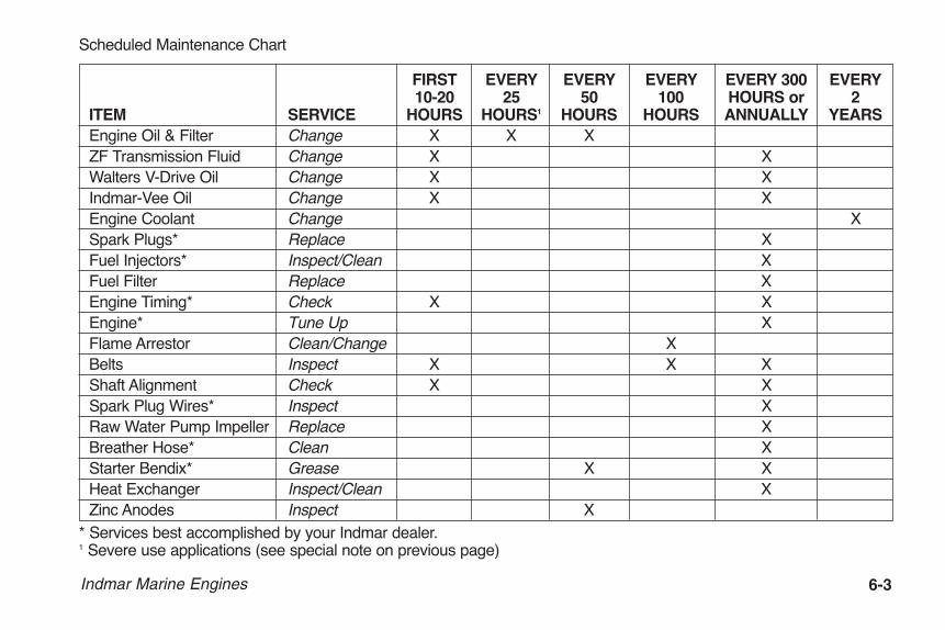
FIRST EVERY EVERY EVERY EVERY 300 EVERY 10-20 25 50 100 HOURS or 2 ITEM SERVICE HOURS HOURS1 HOURS HOURS ANNUALLY YEARS Engine Oil & Filter Change X X X ZF Transmission Fluid Change X X Walters V-Drive Oil Change X X Indmar-Vee Oil Change X X Engine Coolant Change X Spark Plugs* Replace X Fuel Injectors* Inspect/Clean X Fuel Filter Replace X Engine Timing* Check X X Engine* Tune Up X Flame Arrestor Clean/Change X Belts Inspect X X X Shaft Alignment Check X X Spark Plug Wires* Inspect X Raw Water Pump Impeller Replace X Breather Hose* Clean X Starter Bendix* Grease X X Heat Exchanger Inspect/Clean X Zinc Anodes Inspect X* Services best accomplished by your Indmar dealer.1 Severe use applications (see special note on previous page)
OME0502-15 Body.qxp_OM0502-05 Body.qxd 5/20/14 12:45 PM Page 6-3

6-4 Indmar Marine Engines
ENGINE OIL
Oil Consumption
Just because an engine uses oil does not mean it is nothealthy or it is defective. A marine engine gets workedvery hard compared to an automobile engine. When youare cruising down the highway in your car, once it getsup to speed it only takes a small amount of the engine’spower (around 20 HP) to maintain the speed of the vehi-cle on a flat road. A boat, on the other hand, is utilizing asignificantly larger amount of the engine’s output to keepthe boat moving. Then add the extra load of ballast bagsand a wakeboarder, surfer or skier and we are utilizingeven more of the engine’s capacity. The harder you workthe engine, the more consumables (gasoline and oil) itneeds to keep running. As long as there are not otherdetrimental operating characteristics such as low power,oil fouled plugs, constant smoking, etc., do not be con-cerned if the engine uses some oil ... it’s the nature ofthe beast.
Checking Oil
Figure 6.1 – Engine Oil Dipstick Location
Check the oil level with the dipstick every time you getfuel. To get an accurate reading, your engine should bewarm and the boat should be level. For best results waitabout 2 minutes after you turn off the engine to allow theoil to drain into the oil pan, giving you a more accuratereading.
Figure 6.2 – Dipstick
INDM-B001
ADDOPERATING RANGE SEE OWNERS MANUA
INDM-A003
OME0502-15 Body.qxp_OM0502-05 Body.qxd 5/20/14 12:45 PM Page 6-4

Indmar Marine Engines 6-5
1. Pull dipstick from engine.2. Wipe oil off stick with clean towel/cloth.3. Insert dipstick completely into the dipstick tube.4. Remove dipstick and read oil level.5. After reading is complete, return dipstick to tube.6. Add oil if necessary.
Adding Oil
If oil level on the dipstick reads below the ADD mark,add only enough oil to return level to FULL mark.
Figure 6.3 – Engine Oil Fill
Do not overfill. If your oil level is above thefull mark on the dipstick, the engine may bedamaged.
Indmar uses and recommends marine 15W40 in all 5.7Land 6.0L engines and Mobil 1 5W30 in all 6.2L engines.These oils meet or exceed the API Service CI-4 and SL.If 5.7L or 6.0L engines are to be used in conditions below20°F (-7°C), use 10W30 that meets or exceeds theabove API specifications.
The use of engine oil other than the recom-mended viscosity with an API SJ/CG4 desig-nation or better can cause engine damage.Damage to your engine caused by the use ofimproper oils is not covered by your warranty.
MARINE
INDM-A025a
OME0502-15 Body.qxp_OM0502-05 Body.qxd 5/20/14 12:45 PM Page 6-5

6-6 Indmar Marine Engines
Synthetic Oil
For the engines that come from Indmar with conventional oil, synthetic oil that meets our viscosityrequirements and meets or exceeds API SL/SJ/CI-4,CH-4, CG-4 is acceptable to use after 100 hours ofoperation with the recommended oil. The use of syn-thetic oil does not change the requirement of 50 hour(25 hour in severe conditions) oil change intervals.
Changing Oil
Change your engine oil after the first 10-20 hours ofoperation. Then change oil every 50 hours (25 in severe conditions) or annually, whichever comes first. To maximize engine life, change the oil filter at every oil change.
Figure 6.4 – Oil Filter
Indmar recommends all engine maintenance proceduresbe performed by your dealer, including oil changes. Ifyou must perform the oil change yourself, operate theengine to full operating temperature.
INDM-A009
OME0502-15 Body.qxp_OM0502-05 Body.qxd 5/20/14 12:45 PM Page 6-6

Indmar Marine Engines 6-7
Engine oil is hot. Be careful not to burn yourself.
1. With the boat level on trailer, remove the hull or gar-board drain plug and insert QuickDrain through thehull opening (outside of hull).
2. Remove QuickDrain hose cap and let oil flow intoused oil container. When all oil has drained, replacecap and return QuickDrain to storage position.
3. Replace the hull or garboard drain plug. Position asuitable container under the oil filter.
4. Unscrew and remove the oil filter; ensure that filterseal is removed with oil filter. Wipe up any spilled oil inthe bilge and dispose of properly.
5. Fill a new oil filter about 1/2 full with clean engine oil.Lightly lubricate the oil filter gasket and “spin on” thefilter until the gasket makes contact. Hand-tighten filter1/4 to 1/2 turn after contact.
6. Add the new oil through the cap located on theengine valve cover. Fill only to the FULL mark of dip-stick.
7. After initial start up, always carefully inspect oil drainplug and oil filter gasket area for leaks.
8. Stop the engine and re-check oil level. Add if neces-sary.
Oil Additives
Do not use oil additives. Indmar engines do not need oiladditives. Use of recommended oil, along with regular oiland oil filter changes, will protect your engine adequately.
Disposing
Used engine oil contains dangerous chemicals and isconsidered a hazardous waste. Do not allow used oil toremain on your skin for any length of time. Make certainto drain all free flowing oil from the filter prior to disposal.Recycle used oil by taking it to a collection center. If youhave a problem disposing of used oil, ask your Indmardealer or service station for the name of a local oil recy-cling center for proper disposal.
• Prolonged and repeated contact with usedengine oil may cause skin cancer.
• Avoid direct skin contact with used oil. If skincontact is made, wash thoroughly with soapor hand cleaner as soon as possible.
• Keep used engine oil out of reach of children.
• Used engine oil is a hazardous material.Dispose of properly.
OME0502-15 Body.qxp_OM0502-05 Body.qxd 5/20/14 12:45 PM Page 6-7

6-8 Indmar Marine Engines
ENGINE FLAME ARRESTOR
Your engine is equipped with a U.S. Coast Guardapproved flame arrestor. Its purpose is to contain anybackfire that may occur during the operation of yourengine. Because an inboard engine is completelyenclosed, an uncontained backfire can be extremelydangerous.
Figure 6.5 – Flame Arrestor
Periodically inspect flame arrestor to prevent clogging bydirt or corrosion. There are two types of flame arrestorsused in Indmar engines, metal and paper.
K&N Element Type Flame ArrestorIf your engine is eqipped with a K&N high performanceelement type flame arrestor, special procedures arerequired. Special servicing instructions for this flamearrestor can be found on the K&N website, www.knfil-ters.com/cleaning.htm.
When cleaning or replacing the flame arrestor, clean thebreather hose and replace the PCV valve at the sametime.
Do not remove the flame arrester at any timewhen the engine is being started or run as itmay result in fire, explosion and death orserious personal injury.
ENGINE COOLING
Running engine without adequate coolingcan cause engine to overheat and may resultin fire, explosion, death and/or personal serious injury.
INDM-A027
OME0502-15 Body.qxp_OM0502-05 Body.qxd 5/20/14 12:45 PM Page 6-8

Indmar Marine Engines 6-9
Fresh water cooled engines are shipped fromthe Indmar factory filled with a 50/50 mix ofSierra brand antifreeze and water. This mix-ture provides freeze protection down to –26° F(-32° C). If the temperature in your area isexpected to go below this level of protection,see your Indmar dealer to have the antifreezemixture adjusted for your needs.
Running your engine with your boat out ofwater will damage or ruin your engine.Damage to your engine caused by overheat-ing is not covered by your warranty.
Most engines are cooled by the raw water outside of theboat (Open Cooling System). For this reason, do notstart the engine when the boat is out of the water withoutan engine flushing device available from your Indmardealer.
A typical home water supply cannot supplyenough water to operate the engine at highRPM. Do not run the engine above 1000 RPMwhen connected to a hose (home supply).Monitor the engine temperature to ensure theengine does not overheat.
With Open Cooling Systems, if your engine is used insalt, brackish, dirty or polluted water, the cooling systemMUST be flushed with clean water immediately to pre-vent corrosion and blockage in the cooling system.Open Cooling Systems usually consist of a raw waterintake on the bottom of the boat, a raw water pump, abelt driven marine water pump, a thermostat to regulateengine temperature, and various connecting hoses. Theraw water pump pulls outside water through the intake,circulates the water through the engine and then discharges it overboard through a hose or with theengine exhaust.
OME0502-15 Body.qxp_OM0502-05 Body.qxd 5/20/14 12:45 PM Page 6-9

6-10 Indmar Marine Engines
Fresh Water (Closed) Cooling Systems
Some engines havea closed fresh watercooling system. In thefresh water systemthe cooling watercontains anti-freezeand re-circulatesthroughout theengine. If your engineis equipped with aheat exchanger tank,it has a fresh watercooling system. Rawwater is pulledthrough the intakeand flows throughchambers in the heat exchanger and then dischargedoverboard with the engine exhaust.
Check coolant level daily. The level in the coolantrecovery tank should be maintained at the “Full Cold”mark (1, Figure 6.6) when the engine is cold.
To avoid possible skin burns, the engine mustbe turned “OFF” and cool enough so no heatis registered on the temperature gauge. Onlyafter the engine is completely cooled is it safefor you to remove the coolant reservoir cap tocheck the level. Failure to follow proceduremay result in death or serious personal injury.
• Failure to maintain the coolant at the properlevel can cause engine damage. Your war-ranty will not cover engine damage due tooverheating or any other cause associatedwith improper coolant levels.
• Use only propylene glycol coolant. Use ofany other coolant or mixing coolant typescan cause engine damage. Damage to yourengine from use of any other type of coolantis not covered by warranty.
• The coolant system should be flushed andcoolant replaced every two years. Thisshould be performed by a qualified Indmarservice technician.
HOT
COLD
INDM-B002
1
Figure 6.6 – Overflow Tank
OME0502-15 Body.qxp_OM0502-05 Body.qxd 5/20/14 12:45 PM Page 6-10

Indmar Marine Engines 6-11
When adding coolant, add only propylene glycol in anappropriate mixture with distilled water in accordancewith the directions on the container. Do not overfill thetank. Do not mix anti-freeze types.
If the cooling system is completely empty, see yourIndmar dealer for assistance immediately to purge sys-tem. Purging the system is a difficult procedure that isnot recommended for the boat owner.
Salt and Hard Water OperationAll Indmar Marine engines are capable of operating inbrackish or salt water as well as in hard water or waterwith high mineral content as long as certain precautionsand maintenance procedures are followed. Your dealerwill be aware if the local freshwater lakes in your areawill require any special precautions to keep your enginefunctioning properly. Damage to the engine, both internaland external, that is a result of inadequate salt or hardwater maintenance will not be covered under the IndmarLimited Warranty.
The following engines must not be operated in brackishor salt water environments unless equipped with aclosed cooling system which allows the use of anti-freeze coolant in the engine instead of raw water.
• 6.0L – L96• 6.2L – LS3 and LSA
These engines use aluminum cylinder heads and/orblock assemblies which will be severely damaged fromsalt water corrosion if operated in brackish or salt water.Factory-installed closed cooling systems are available forthe 6.0L and the 6.2L LS3 engines. These engines mustbe ordered from the factory as closed cooled engines.No field-installed closed cooling kits are available.
There is no closed cooling system available for the 6.2LLSA engine. This engine is not designed to be used insalt water.
The 5.7L Indmar engines will tolerate occasional use insalt water but it is recommended that if the engine will beused in salt water more that 25% of the time that theengine be equipped with a closed cooling system.
OME0502-15 Body.qxp_OM0502-05 Body.qxd 5/20/14 12:45 PM Page 6-11
6-12 Indmar Marine Engines
External CareYour engine has been carefully primed and painted toprotect it against rust and corrosion. To keep your enginelooking like new, Indmar recommends applying an anti-corrosion compound. Regular application (every 3months) of this Protectant, particularly on exposed metalsurfaces, motor mounts and electrical connections, willdisplace water and seal the surfaces against penetrationby corrosive agents. Rinsing the engine with fresh waterbetween applications of the Protectant will further protectthe exposed surfaces.
INTERNAL (COOLING SYSTEM) CARE
Raw Water Cooling SystemsIf your engine is raw water cooled, water from whateverbody of water you are operating in is pumped throughthe cooling passages of the engine, exhaust manifoldsand exhaust risers. It is critical that the salt water beflushed from these cooling passages after use by run-ning fresh water through the cooling system. For moreconvenient flushing, ask your dealer about permanentlyinstalling a flushing device that allows easy connection ofa water hose.
Fresh Water Cooling – Half SystemsA fresh water cooling system that uses anti-freeze in theengine but raw water in the exhaust manifolds is referredto as a half-system. Although the engine is protected, itis still important to flush the engine with fresh water toremove as much salt water as possible from the rawwater side of the cooling system as well as from theexhaust manifolds and risers. For more convenient flush-ing, ask your dealer about permanently installing a flush-ing device that allows easy connection of a water hose.
Even with diligent flushing, certain cast iron exhaust sys-tem components called exhaust risers or exhaust elbowswill be significantly affected by salt water. These risersmust be inspected annually and replaced as required. Itis not unusual to have to replace these risers every twoor three years on boats used exclusively in salt water.
OME0502-15 Body.qxp_OM0502-05 Body.qxd 5/20/14 12:45 PM Page 6-12
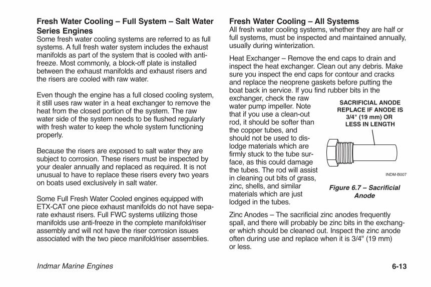
Indmar Marine Engines 6-13
Fresh Water Cooling – Full System – Salt WaterSeries EnginesSome fresh water cooling systems are referred to as fullsystems. A full fresh water system includes the exhaustmanifolds as part of the system that is cooled with anti-freeze. Most commonly, a block-off plate is installedbetween the exhaust manifolds and exhaust risers andthe risers are cooled with raw water.
Even though the engine has a full closed cooling system,it still uses raw water in a heat exchanger to remove theheat from the closed portion of the system. The rawwater side of the system needs to be flushed regularlywith fresh water to keep the whole system functioningproperly.
Because the risers are exposed to salt water they aresubject to corrosion. These risers must be inspected byyour dealer annually and replaced as required. It is notunusual to have to replace these risers every two yearson boats used exclusively in salt water.
Some Full Fresh Water Cooled engines equipped withETX-CAT one piece exhaust manifolds do not have sepa-rate exhaust risers. Full FWC systems utilizing thosemanifolds use anti-freeze in the complete manifold/riserassembly and will not have the riser corrosion issuesassociated with the two piece manifold/riser assemblies.
Fresh Water Cooling – All SystemsAll fresh water cooling systems, whether they are half orfull systems, must be inspected and maintained annually,usually during winterization.
Heat Exchanger – Remove the end caps to drain andinspect the heat exchanger. Clean out any debris. Makesure you inspect the end caps for contour and cracksand replace the neoprene gaskets before putting theboat back in service. If you find rubber bits in theexchanger, check the rawwater pump impeller. Notethat if you use a clean-outrod, it should be softer thanthe copper tubes, andshould not be used to dis-lodge materials which arefirmly stuck to the tube sur-face, as this could damagethe tubes. The rod will assistin cleaning out bits of grass,zinc, shells, and similarmaterials which are justlodged in the tubes.
Zinc Anodes – The sacrificial zinc anodes frequentlyspall, and there will probably be zinc bits in the exchang-er which should be cleaned out. Inspect the zinc anodeoften during use and replace when it is 3/4" (19 mm) or less.
SACRIFICIAL ANODEREPLACE IF ANODE IS
3/4" (19 mm) OR LESS IN LENGTH
INDM-B007
Figure 6.7 – SacrificialAnode
OME0502-15 Body.qxp_OM0502-05 Body.qxd 5/20/14 12:45 PM Page 6-13

6-14 Indmar Marine Engines
Raw Water Pump – Replace the impeller if it is worn orover one year old. Since you must remove the impellerto inspect it, it is good practice to replace the impellerevery year as a routine. Be sure there are no impellerparts lodged in the hoses or elsewhere in the system asthey will eventually move to an inconvenient place andrestrict water flow. The raw water pump impeller shouldbe replaced every year or whenever it is found to be worn or have damaged blades. Be sure to re-assemble with the proper gaskets.
Figure 6.8 – Raw Water Pump Impeller
FUEL SYSTEM
The fuel system consists of fuel lines, fuel pump, and anunused fuel recovery system. Fuel in the system isunder pressure and must be relieved before servicing.Because of the inherent danger of fuel leakage into thebilge, do not attempt servicing or maintaining compo-nents of the fuel system.
Your Indmar dealer has factory trained technicians andU.S. Coast Guard approved marine grade parts requiredfor fuel systems.
TRANSMISSIONS
NOTICEIt is important to keep the water level in the bilge belowthe output shaft of the transmission. If the water level inthe bilge is too high, the coupler can splash waterinside the engine compartment and cause corrosionproblems. High water levels can also allow water intru-sion into the transmission causing severe damage.
Indmar engines are equipped with one of these marinetransmissions:
• ZF Hurth Marine In-Line• ZF Hurth Ski-Vee• Walters V-Drive and ZF Hurth In-Line• Indmar-Vee
INDM-A036
OME0502-15 Body.qxp_OM0502-05 Body.qxd 5/20/14 12:45 PM Page 6-14

Indmar Marine Engines 6-15
1. Dipstick
Figure 6.9 – Midships Mount, ZF Hurth Marine In-Line
1. Dipstick
Figure 6.10 – Stern Mount, ZF Hurth Ski-Veeor Indmar-Vee Throughshaft Models
1 1
1
OME0502-15 Body.qxp_OM0502-05 Body.qxd 5/20/14 12:45 PM Page 6-15

6-16 Indmar Marine Engines
1. Dipstick
Figure 6.11 – Stern Drive, Walters V-Drive and ZF Hurth In-Line
1. Dipstick
Figure 6.12 – Stern Mount, ZF Hurth Ski-Vee or Indmar-Vee Undershaft Models
1
1
1
1
OME0502-15 Body.qxp_OM0502-05 Body.qxd 5/20/14 12:45 PM Page 6-16

Indmar Marine Engines 6-17
A separate owner’s manualcovering basic maintenanceis provided with each trans-mission. The transmissionfluid must be changed andthe filter cleaned after thefirst 10-20 hours of opera-tion and once each yearthereafter. Refer to thetransmission owner’s manual for information.
The transmission is watercooled by a heat exchangerconnected to the enginecooling system. The trans-mission fluid level should bechecked daily. Fluid level isto be maintained at a levelbetween the “Full” and“Add” marks on the transmission dipstick.
Overfilling the transmission with fluid will cause the sealsto leak, and eventually lead to overheating. When thereis too little fluid, over-heating will result.
If the engine uses the Walters V-Drive, it is equipped witha ZF Hurth in-line transmission for shifting. Be aware thatthe Walters V-Drive uses motor oil for lubrication, whilethe ZF Hurth transmission uses Automatic TransmissionFluid. The Walters V-Drive also has a low oil pressuresensor and a dashboard mounted light. If low oil pressure is sensed, this lamp will light indicating theproblem. Shut down the engine and check the transmis-sion fluid level. Refer to Section 4, Check TransmissionLight for more information.
If transmission service is required, note the SerialNumber of the transmission stamped onto the ID plateon the top of the transmission housing. It is good practice to note the serial number and keep it with otherowner related information.
Checking/Adding Transmission Fluid
Transmission fluid may be hot.
NOTE: Refer to page 6-18 for correct transmission andfluid capacities for your model of transmission.
HIGH
LOW
INDM-A039
Figure 6.13 – Walters V-Drive Dipstick
OME0502-15 Body.qxp_OM0502-05 Body.qxd 5/20/14 12:45 PM Page 6-17

6-18 Indmar Marine Engines
TRANSMISSION MODEL CAPACITY FLUID TYPE ZF Hurth In-Line ZF 45C 1.7 qt (1.6 L) Dexron ATF ZF Hurth In-Line ZF 45A 2.12 qt (2 L) 15W40 Motor Oil ZF Hurth In-Line ZF 63A 4.2 qt (4 L) 15W40 Motor Oil ZF Hurth V-Drive ZF 63IV 4.2 qt (4 L) 15W40 Motor Oil ZF Hurth V-Drive ZF 45IV 2.12 qt (2 L) Main Gearbox Dexron ATF 1.0 qt (1.06 L) V-Drive Unit Dexron ATF Walters V-Drive RV-26D-71V 0.5 qt (0.5 L) 15W40 Motor Oil Indmar V – 2.3 qt (2.18 L) Main Gearbox Dexron ATF 1.25 qt (1.18 L) V-Drive Unit Mobil Delvac Synthetic 50
Check fluid immediately after turning the engine “OFF”and boat floating level, or level on trailer. The transmissiondipstick is located on the top of the transmission. Dipsticksmay be marked “ADD” and “FULL” or “H” and “L” (highand low); maintain fluid level between the two marks.
1. Remove the dipstick and wipe with a clean towel.
2. Insert the dipstick completely (do not screw in threadeddipstick to check fluid). Remove the dipstick and readfluid level.
3. Return dipstick after level check. Make sure it issecured in place.
4. If level is below “ADD” mark, add the proper fluid until itreaches the full mark. Add fluid through same tube asyou removed the transmission dipstick.
NOTICEDo not overfill the transmission. Overfilling can damagethe transmission. Damage to your transmission due to toomuch or too little fluid is not covered by your warranty.
OME0502-15 Body.qxp_OM0502-05 Body.qxd 5/20/14 12:45 PM Page 6-18

Indmar Marine Engines 6-19
ELECTRICAL SYSTEM
All Indmar engines are equipped with a 40 A Maxi-Fuse(1, Figure 6-14) to protect the engine electrical systemand components from overload. If the engine will notcrank with the battery switch in the ON position, locatethe fuse at the back of the engine. It is located under thefuse block cover. Replace the 40 A Maxi-Fuse with thespare from the fuse block (2, Figure 6-14). Start theengine.
Figure 6.14 – 40 A Maxi-Fuse
If the fuse blows again, there is a problem with the elec-trical system. Take your boat immediately to your Indmardealer for repair.
NOTICEIn addition to the 40 A fuse, EFI engines are equippedwith additional component overload protection.
Figure 6.15 – Fuse Block
EFI fuses are located in the holder (Figure 6-15)attached by the ECM. To remove or inspect a fuse,remove molded plastic cap from fuse holder. Inspectfuse and replace if it is defective. Make sure to replacethe fuse block cover when finished.
MODEL #E-6123P/N: E2321993
COMPLIES TO MARINE SAE J1171
SPARE
SPARE SPARE SPARE SPARE
FUSES UNDER
F9-EMPTY
20A20A
20A20A
20A
20A5A
40A
F8-HELM
F7-MAIN BREAKERF5-FUEL PUMP 2
F6-STARTER
F3-FUEL PUMP
F1-VSWF2-ECM
STARTERRELAY
F4-PTR
POWERRELAY
FUEL PUMPRELAY
COVER
INDM-0028
1
2
MO
DEL
#E-6
123
P/N:
E23
2199
3
CO
MPL
IES
TO M
AR
INE
SAE
J117
1
SPA
RE
SPA
RE
SPA
RE
SPA
RE
SPA
RE
FUSE
SU
ND
ER
F9-EMPTY
20A 20A
20A 20A
20A
20A5A
40A
F8-HELM
F7-MAIN BREAKER F5-FUEL PUMP 2 F6-STARTER
F3-FUEL PUMP
F1-VSW F2-ECM
STARTERRELAY
F4-PTR
POW
ERR
ELAY
FUEL
PU
MP
REL
AY
CO
VER
INDM-0002
OME0502-15 Body.qxp_OM0502-05 Body.qxd 5/20/14 12:45 PM Page 6-19

6-20 Indmar Marine Engines
WIRING
If during maintenance or inspection, it becomes neces-sary to move or reposition any of the engine’s wiring orwire harnesses, verify that wiring is returned to its origi-nal position, and that all harnesses are routed correctly. If a wiring clip or retainer breaks, replace it immediately.Wiring is specifically routed to eliminate problems relatedto engine heat and spray, immersion in liquids, or contactwith rotating assemblies. Electrical problems can result ifwiring is moved from its original position and is not prop-erly repositioned.
Charging System Maintenance / GuidelinesAdhering to the following procedures and guidelines willensure proper operation of your battery charging system.Watch out for:
1. REVERSE BATTERY POLARITY: When reconnectingthe battery after winter storage, it is easy to accidental-ly reverse the battery leads and connect positive tonegative and negative to positive. This generallyresults in a large arc at the battery terminals and fail-ure of the diodes and/or regulator in the alternator aswell as other components in the electrical system ofthe engine or boat that are polarity sensitive such asignition modules, ECMs, stereos, etc. For several com-ponents to fail at the same time, the failures are gener-ally due to some external influence such as reversedbattery leads or reversed jumper leads. These types offailures are not covered by Indmar’s Limited Warranty.
2. POOR CONNECTIONS: When there is a defectiveconnection between the battery and alternator, charg-ing current will be forced to find an alternate route toflow out toward the battery. A defective connectionmay be caused by corrosion or an open circuit from abreak in several battery cable strands or simply aloose connection. The alternate route that currentfinds usually leads to excessive current flow, causingthe diodes in the alternator to overheat and fail. It iscritical that all electrical connections are clean andtight.
3. POSITIVE CIRCUIT FAULTS: A bad connection oropen circuit between the alternator output terminaland the positive battery terminal will force the charg-ing current to follow a parallel route through the diodetrio and out of the alternator. This heavier than normalcurrent flows though the diodes and will cause themto overheat and fail. Consequently, if you havereplaced an alternator because of bad diodes, and thereplacement fails for the same reason, there is likely abad connection between the alternator BAT (B+) ter-minal and the positive side of the battery circuit. Haveyour dealer do a voltage drop test to check the entirecircuit. Also, never remove a battery cable when theengine is running. This will cause the diodes to over-heat and fail. Never use the alternator to bring anundercharged battery to a fully charged condition. Theexcessive current draw can overheat the diodes andcause them to fail.
OME0502-15 Body.qxp_OM0502-05 Body.qxd 5/20/14 12:45 PM Page 6-20

Indmar Marine Engines 6-21
4. NEGATIVE (GROUND) CIRCUIT FAULTS: The pri-mary mount of the alternator serves as the negativeground for the alternator. This connects the alternatorto the engine block which is in turn connected to thenegative post of the battery via a ground stud on theengine. The ground stud on the engine holds all of thewiring harness grounds and battery ground with onenut and it is known to occasionally become loose, dis-connected or corroded. When the alternator loses itsground, it can become damaged as it surges andcould cause catastrophic damage to the voltage regu-lator within the alternator. It is important to keep theground wires, stud and nut clean and tight and checkit often.
5. OVERLOADED: Never use the alternator to bring adead or undercharged battery to a fully charged con-dition. The excessive current draw can overheat thediodes and cause them to fail. If you have a dead bat-tery, use a battery charger instead. If you experiencea battery that is constantly being discharged, look forthe cause, such as bad battery or aftermarket acces-sories, or defective electrically operated accessories.Find the cause of the discharge before permanentdamage is done.
General Lubrication
STARTER
Apply a dab of multipurpose grease onto the starter ben-dix every month or 50 hours of operation. Your starterhas been sprayed with lubrication internally to extend itslongevity.
SHIFT AND THROTTLE CABLES
Spray exposed throttle cable and transmission cableends with multipurpose grease. Work the cable back andforth, then spray to completely lubricate. In highly corro-sive locations, a complete cable lubrication system maybe purchased through your Indmar dealer.
OME0502-15 Body.qxp_OM0502-05 Body.qxd 5/20/14 12:45 PM Page 6-21

6-22 Indmar Marine Engines
OME0502-15 Body.qxp_OM0502-05 Body.qxd 5/20/14 12:45 PM Page 6-22

Indmar Marine Engines 7-1
Storage or winter lay-up requires preparation to preventdamage to the power package. While preparing thepower package for winter lay-up, annual maintenancetasks should also be performed.
Without proper preparation, storage over a long period oftime may cause internal engine and transmission partsto rust due to lack of lubrication. Also, if the boat is storedwhere the temperature falls below freezing, any waternot drained from the engine may freeze, resulting insevere damage. Damage that is the result of improperstorage is not covered under terms of Indmar’s limitedwarranty.
Because of the complexity of preparing yourengine for winter storage, and the danger ofcatastrophic engine damage from freezingwater in the engine, it is recommended thatyou have your dealer perform winterizationprocedures. Damage due to by improper win-terization/storage is not covered by productwarranty!
To properly winterize your engine, you MUST be able tobring the engine up to operating temperature. To accom-plish this, your boat must be in the water, or be attachedto a water supply using a hose and suitable adapter thatwill allow an uninterrupted supply of water to the engine.
Chapter 7STORAGE AND WINTER LAY-UP
OME0502-15 Body.qxp_OM0502-05 Body.qxd 5/20/14 12:45 PM Page 7-1

7-2 Indmar Marine Engines
NOTICEThis procedure covers only the power package por-tion of your boat. Consult your boat owner’s manualor boat manufacturer for specific boat winterizinginstructions.
GENERAL PREPARATIONBefore beginning you will need the following supplies:• Sta-Bil Gasoline Stabilizer• 6 quarts of Appropriate Engine Oil
(10 quarts for 8.1 Liter)• 501001 Oil Filter for 5.7 Liter Carbureted and EFI
Engines• 501018 Oil Filter for 6.0 and 6.2 Liter Engines• 4-6 ounces of Marine Fogging Oil• 1 can Corrosion Protectant and Lubricant • Transmission Oil (As Required)• Multipurpose Grease • Short Piece of Stiff Wire (Coat hanger wire)• Pipe Thread Sealant• Anti-Freeze Tester suitable for Propylene Glycol
(Fresh Water Cooled Engines Only)• Propylene Glycol Anti Freeze (As required for Fresh
Water Cooled Engines Only)
Fuel System Treatment1. If the boat is to be placed in storage with fuel in the
tank(s) that does not contain alcohol, fill the fueltank(s) with fresh fuel and a sufficient amount ofMarine Formula Sta-Bil gasoline stabilizer to treat theentire tank. Follow instructions on the container.
2. Start the engine and operate at Idle RPM until theengine reaches normal operating temperature. (Ifusing a hose and adapter, adjust the faucet to avoidover-cooling the engine at low RPM.) Run the enginefor at least 15 minutes to ensure that the fuel stabiliz-er enters the engine’s fuel system.
Running the engine with the flame arrestorremoved increases the possibility of fire orexplosion if engine backfire occurs andgasoline fumes are present. If the engine isoperated without the flame arrestor secured,extreme care must be taken to ensure thatthe engine compartment is well ventilatedand that no fuel leaks are present.
OME0502-15 Body.qxp_OM0502-05 Body.qxd 5/20/14 12:45 PM Page 7-2

On catalytic converter-equipped engines,Indmar does not recommend applying fog-ging oil while the engine is running. The fog-ging oil could damage the catalytic convert-er. The cylinders must be protected byremoving the spark plugs and applying thefogging oil directly into the cylinders.
3. On catalytic converter-equipped engines, remove thespark plugs and apply the storage lubricant directly inthe cylinders. After all the cylinders have been treat-ed, crank the engine to spread the lubricant on thecylinder walls. Replace the spark plugs in the engine.
4. Perform annual maintenance, refer to Chapter 6,Scheduled Maintenance Chart.
5. Loosen all accessory drive belts and check condition.Replace belt(s) if cracked or damaged.
6. Drain seawater section of the cooling system.
NOTICEPlacing all drain plugs, impeller, etc. in a plastic bagand attaching the bag to the steering wheel of theboat is a good reminder to reinsert the plugs whenyou recommission the boat in the spring.
All Engines:1. Drain water from exhaust manifolds except on salt
water series engines. Uncouple the hose quick disconnect and drain the manifolds. Indmar recommends that you leave the drain plugs out, or the hose uncoupled, until spring.
2. Remove both hoses from the seawater pump on thefront of the engine. Drain any remaining water fromthe hoses.
Indmar Marine Engines 7-3
OME0502-15 Body.qxp_OM0502-05 Body.qxd 5/20/14 12:45 PM Page 7-3

7-4 Indmar Marine Engines
Figure 7.1 – Quick Disconnect
Figure 7.2 – Raw Water Pump Impeller
3. Remove the raw water pump impeller from the pumphousing. Replace annually.
4. Remove the hose from the lower (rear) end of thetransmission cooler. Inspect the cooler for any debrissuch as weeds, plastic, etc.
INDM-A038
INDM-A036
OME0502-15 Body.qxp_OM0502-05 Body.qxd 5/20/14 12:45 PM Page 7-4

Indmar Marine Engines 7-5
Figure 7.3 – Transmission Cooler
Drive Train Preparation
1. Change the transmission fluid following the instruc-tions in the transmission owner’s manual.
2. Drain the water from the cooling section of the V-drive transmission.
a. ZF Ski-Vee. On these units, you can drain thewater by removing the two anodes (1, Figure 7.4)or by removing one of the hoses that areattached to the unit. If the sacrificial portion of theanodes is less than 3/8" (9 mm), they must bereplaced.
Figure 7.4 – ZF Ski-Vee Water Drains
INDM-A009
INDM-0024a1
OME0502-15 Body.qxp_OM0502-05 Body.qxd 5/20/14 12:45 PM Page 7-5

7-6 Indmar Marine Engines
b. ZF Through-Shaft Ski-Vee. On these models,you must remove the hose from the fitting that ispointed toward the engine to drain the cooler.
Figure 7.5 – ZF Through-Shaft Ski-Vee Water Drains
c. Indmar-Vee. On these models, you must removethe plug from the rear of the V-drive to drain thecooler.
Figure 7.6 – Indmar-Vee Drain Plug
INDM-0025aINDM-0023
OME0502-15 Body.qxp_OM0502-05 Body.qxd 5/20/14 12:45 PM Page 7-6

Indmar Marine Engines 7-7
d. Indmar-Vee Through Shaft. On these models,you must remove the plug from the rear of the V-drive to drain the cooler.
Figure 7.7 – Indmar-Vee Through Shaft Drain Plug
e. Walter V-Drive. On these models, you can drainthe water from the cooler by removing one of thewater drain plugs.
Figure 7.8 – Walter V-Drive Drain Plugs
INDM-0022
INDM-0026
OME0502-15 Body.qxp_OM0502-05 Body.qxd 5/20/14 12:45 PM Page 7-7

7-8 Indmar Marine Engines
Raw Water Cooled Engines
NOTICEPlacing the drain plugs in a plastic bag and attachingit to the steering wheel of the boat will act as areminder to reinstall the drain plugs during recommis-sioning in spring.
1. Remove the drain plug or sensor from each side ofthe engine.
Figure 7.9 – Anti Knock Sensor
NOTICESome 5.7 Liter engines have a knock sensorlocated in the drain locations on both sides ofthe engine. The knock sensor and knock sen-
sor stud must be carefully removed to drain that sideof the block.
NOTICEOn the 6.0 and 6.2 Liter engines, removing the knocksensor does NOT drain the block. Remove the capsfrom the brass hose fittings on both sides of theengine to drain water from the block.
2. Use a short piece of stiff wire and poke around in thedrain hole to ensure that any rust or scale is brokenapart, and the engine drains completely.
3. Disconnect the large diameter hose that runs fromthe water-circulating pump to the thermostat housing.Make sure all of the water drains from the hose.
IND-A005A
1
OME0502-15 Body.qxp_OM0502-05 Body.qxd 5/20/14 12:45 PM Page 7-8
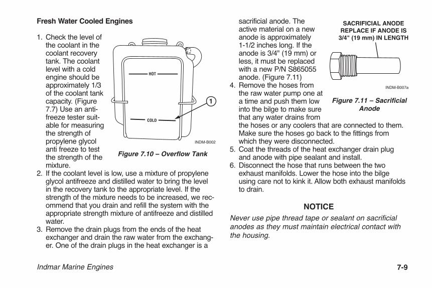
Indmar Marine Engines 7-9
Fresh Water Cooled Engines
1. Check the level ofthe coolant in thecoolant recoverytank. The coolantlevel with a coldengine should beapproximately 1/3of the coolant tankcapacity. (Figure7.7) Use an anti-freeze tester suit-able for measuringthe strength ofpropylene glycolanti freeze to testthe strength of themixture.
2. If the coolant level is low, use a mixture of propyleneglycol antifreeze and distilled water to bring the levelin the recovery tank to the appropriate level. If thestrength of the mixture needs to be increased, we rec-ommend that you drain and refill the system with theappropriate strength mixture of antifreeze and distilledwater.
3. Remove the drain plugs from the ends of the heatexchanger and drain the raw water from the exchang-er. One of the drain plugs in the heat exchanger is a
sacrificial anode. Theactive material on a newanode is approximately 1-1/2 inches long. If theanode is 3/4" (19 mm) orless, it must be replacedwith a new P/N S865055anode. (Figure 7.11)
4. Remove the hoses fromthe raw water pump one ata time and push them lowinto the bilge to make surethat any water drains fromthe hoses or any coolers that are connected to them.Make sure the hoses go back to the fittings fromwhich they were disconnected.
5. Coat the threads of the heat exchanger drain plugand anode with pipe sealant and install.
6. Disconnect the hose that runs between the twoexhaust manifolds. Lower the hose into the bilgeusing care not to kink it. Allow both exhaust manifoldsto drain.
NOTICENever use pipe thread tape or sealant on sacrificialanodes as they must maintain electrical contact withthe housing.
HOT
COLD
INDM-B002
1
Figure 7.10 – Overflow Tank
SACRIFICIAL ANODEREPLACE IF ANODE IS
3/4" (19 mm) IN LENGTH
INDM-B007a
Figure 7.11 – SacrificialAnode
OME0502-15 Body.qxp_OM0502-05 Body.qxd 5/20/14 12:45 PM Page 7-9
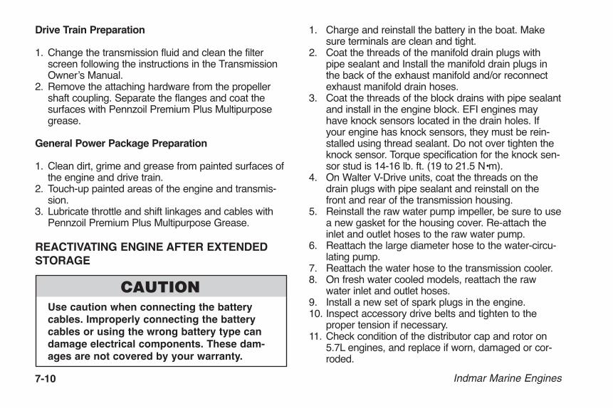
7-10 Indmar Marine Engines
Drive Train Preparation
1. Change the transmission fluid and clean the filterscreen following the instructions in the TransmissionOwner’s Manual.
2. Remove the attaching hardware from the propellershaft coupling. Separate the flanges and coat the surfaces with Pennzoil Premium Plus Multipurposegrease.
General Power Package Preparation
1. Clean dirt, grime and grease from painted surfaces ofthe engine and drive train.
2. Touch-up painted areas of the engine and transmis-sion.
3. Lubricate throttle and shift linkages and cables withPennzoil Premium Plus Multipurpose Grease.
REACTIVATING ENGINE AFTER EXTENDEDSTORAGE
Use caution when connecting the batterycables. Improperly connecting the batterycables or using the wrong battery type candamage electrical components. These dam-ages are not covered by your warranty.
1. Charge and reinstall the battery in the boat. Makesure terminals are clean and tight.
2. Coat the threads of the manifold drain plugs withpipe sealant and Install the manifold drain plugs inthe back of the exhaust manifold and/or reconnectexhaust manifold drain hoses.
3. Coat the threads of the block drains with pipe sealantand install in the engine block. EFI engines mayhave knock sensors located in the drain holes. Ifyour engine has knock sensors, they must be rein-stalled using thread sealant. Do not over tighten theknock sensor. Torque specification for the knock sen-sor stud is 14-16 lb. ft. (19 to 21.5 N•m).
4. On Walter V-Drive units, coat the threads on thedrain plugs with pipe sealant and reinstall on thefront and rear of the transmission housing.
5. Reinstall the raw water pump impeller, be sure to usea new gasket for the housing cover. Re-attach theinlet and outlet hoses to the raw water pump.
6. Reattach the large diameter hose to the water-circu-lating pump.
7. Reattach the water hose to the transmission cooler.8. On fresh water cooled models, reattach the raw
water inlet and outlet hoses.9. Install a new set of spark plugs in the engine.10. Inspect accessory drive belts and tighten to the
proper tension if necessary.11. Check condition of the distributor cap and rotor on
5.7L engines, and replace if worn, damaged or cor-roded.
OME0502-15 Body.qxp_OM0502-05 Body.qxd 5/20/14 12:45 PM Page 7-10

Indmar Marine Engines 7-11
12. If the fuel tank was drained, fill tank with fresh fuelthat does not contain alcohol.
13. Check all fluid, oil and coolant levels on engine anddrive train.
14. Check engine compartment and bilge for nesting ani-mals. Clean as necessary. Check for any damage orevidence of fluid leaks.
15. Check alignment between the output flange on thetransmission and the prop shaft flange. If the maxi-mum feeler gauge that can slip between the flangefaces at any point is 0.003" (0.08 mm), the unit isproperly aligned. If a thicker gauge can be inserted atany point, the engine must be readjusted until properalignment is obtained.
Figure 7.12 – Prop Shaft Flange Alignment
NOTICEWith the boat in the water or a hose and adapterinstalled, cycle the key switch ON, then OFF, for fivesecond intervals 2-4 times before cranking the engineto allow the fuel pump to prime the fuel lines.
16. Review boat manufacturers starting procedure.
17. Start the engine. If you experience a no-start condi-tion, do not crank the engine for more than 15 sec-onds without allowing a two minute cool-down peri-od. When the engine starts, keep a close watch onthe gauge readings. Check all of the hoses and drainplugs for leaks. Listen for abnormal noises. Run theengine long enough to reach normal operating tem-perature and re-inspect for leaks. If no leaks arefound, the boat is ready for operation.
0.003"
INDM-A037
OME0502-15 Body.qxp_OM0502-05 Body.qxd 5/20/14 12:45 PM Page 7-11

7-12 Indmar Marine Engines
EXTENDED STORAGEIf you must store your boat for an extended period oftime (more than normal off-season storage), additionalprocedures are required. The procedures for preparingfor extended storage and re-commissioning after extended storage are best accomplished by an authorized Indmar dealer.
1. Follow the normal procedures for off-season storage.2. Disconnect the propeller shaft from the output shaft
coupling on the transmission.
Re-commissioning
1. Follow the normal procedures for re-commissioningafter off-season storage.
2. Check the propshaft to transmission coupler align-ment. Adjust as necessary. Connect the propshaftand transmission coupler.
3. Remove and clean the fuel injectors and flush theentire fuel system.
4. Install a new fuel filter.5. Change all of the engine fluids and lubricants. Install
a new oil filter.6. Install a new raw water pump impeller.7. Check all belts and hoses for cracks and wear.
Replace as needed.8. Install new spark plugs. Check the wires for cracks
and damage.
9. Charge the battery and check battery connections tomake sure they are clean and tight.
10. Put fresh gasoline in the fuel tank. Cycle the keyswitch several times to make sure the fuel system is full and primed. Install an appropriate tester andverify the fuel pressure is at specification.
11. Apply water to the engine’s cooling system and startthe engine. While the engine is warming up, checkfor leaks and smooth engine operation. Monitor thefuel pressure to make sure it stays in specification.
12. Put the boat in the water and operate it at variousRPM. Monitor the engine temperature, oil pressure,charging voltage and fuel pressure to make sure allstay within specification. Check the various engineoperating parameters with a diagnostic scan tool tomake sure all parameters are within specification.
OME0502-15 Body.qxp_OM0502-05 Body.qxd 5/20/14 12:45 PM Page 7-12

Indmar Marine Engines 8-1
Your Indmar engine is manufactured under strict qualitycontrol standards. It is tested along with a full spectrumgas analysis. It is operating at optimum levels before it isshipped.
Difficulties can occur. Use the following problemdiagnosis charts to help pinpoint problems. In mostcases, you will need the assistance of your Indmar deal-er to correct the cause of the problem.
Poor Gas Mileage1. Fouled spark plugs2. Plugged flame arrestor3. Poor driving habits4. Closed or partially closed choke (carbureted
engines only)5. Plugged positive crankcase ventilation system6. Black smoke at exhaust outlet shows rich gas mixture7. Excessive boat loads (weight)8. Damaged or dirty hull9. High altitude adjustment required10. Adjustment for temperature extremes required
Hard Cold Start1. Weak or discharged battery2. Choke held open (carbureted engines only)3. Loose coil or ignition wires4. Engine Flooded5. Fouled spark plugs6. Lack of fuel at carburetor (carbureted engines only)7. Battery cables loose or corroded8. Loose electrical grounds at engine9. Ignition switch problems10. Dirt or water in fuel system11. Engine needs tune-up
Poor High Speed Performance1. Fouled spark plugs, incorrect spark plug gap or heat
range2. Closed or partially closed choke (carbureted
engines only)3. Dirt or water in fuel4. Lack of fuel in carburetor (carbureted engines only)5. Restricted exhaust system6. Plugged flame arrestor
Chapter 8TROUBLESHOOTING
OME0502-15 Body.qxp_OM0502-05 Body.qxd 5/20/14 12:45 PM Page 8-1

8-2 Indmar Marine Engines
7. Insufficient air supply to engine8. Engine needs tune-up9. Damaged or incorrect propeller10. Engine needs to be adjusted for high altitude operations11. Engine needs to be adjusted for temperature
extremes
Engine Cranks / Won’t Start1. Weak or shorted coil; no spark at plugs2. Loose engine grounds3. Lack of fuel at carburetor (carbureted engines only)4. Weak or discharged battery5. Boat Engine Safety switch not attached6. Vapor lock
Idle — Misses or Runs Rough1. Spark plugs fouled or cracked2. Spark plug or distributor wires loose or shorted3. Plugged positive crankcase ventilation system4. Engine in need of tune-up5. Engine needs to be adjusted for high altitude operations6. Engine needs to be adjusted for temperature
extremes7. Carburetor out of adjustment (carbureted engines
only)
Hard Start Hot1. Flooding condition2. Loose electrical ground at engine3. Closed choke (carbureted engines only)4. Plugged flame arrestor5. Fouled spark plugs6. Loose coil or ignition wires7. Battery cables loose or corroded8. Weak or discharged battery 9. Vapor lock
Engine Won’t Crank1. Weak or discharged battery; loose or corroded battery cables2. Defective neutral safety switch or adjustment needed3. Defective starter motor4. Ignition switch problems5. Hydrostatic lockup — remove spark plugs to look for
water or gasoline in cylinders6. Seized engine — turn crank pulley with socket and
ratchet
OME0502-15 Body.qxp_OM0502-05 Body.qxd 5/20/14 12:45 PM Page 8-2
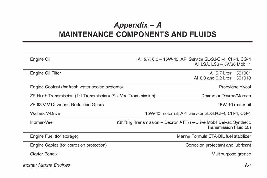
Indmar Marine Engines A-1
Engine Oil All 5.7, 6.0 – 15W-40, API Service SL/SJ/CI-4, CH-4, CG-4All LSA, LS3 – 5W30 Mobil 1
Engine Oil Filter All 5.7 Liter – 501001All 6.0 and 6.2 Liter – 501018
Engine Coolant (for fresh water cooled systems) Propylene glycol
ZF Hurth Transmission (1:1 Transmission) (Ski-Vee Transmission) Dexron or Dexron/Mercon
ZF 63IV V-Drive and Reduction Gears 15W-40 motor oil
Walters V-Drive 15W-40 motor oil, API Service SL/SJ/CI-4, CH-4, CG-4
Indmar-Vee (Shifting Transmission – Dexron ATF) (V-Drive Mobil Delvac Synthetic Transmission Fluid 50)
Engine Fuel (for storage) Marine Formula STA-BIL fuel stabilizer
Engine Cables (for corrosion protection) Corrosion protectant and lubricant
Starter Bendix Multipurpose grease
Appendix – AMAINTENANCE COMPONENTS AND FLUIDS
OME0502-15 Body.qxp_OM0502-05 Body.qxd 5/20/14 12:45 PM Page A-1

A-2 Indmar Marine Engines
Alternator Belts All Indmar 5.7L with V-belt – Indmar 725018All Indmar 5.7L with Serpentine Belt – Indmar 725034
All Indmar 6.0L L96 – Indmar 725028All 6.2L LS3 – Indmar 725038
All 6.2L LSA Accessory Belt – Indmar 725041All 6.2L LSA Supercharger Belt – Indmar 725043
Thermostats All 5.7L Raw Water Cooled – Indmar 985009All 5.7L Fresh Water Cooled – Indmar 986034
All 6.0L and 6.2L LS3 Raw Water Cooled – Indmar 985009All 6.0L and 6.2L LS3 Fresh Water Cooled – Indmar 986115
All 6.2L LSA – Indmar 986115
Spark Plugs All 5.7L Carbureted Engines 41-101 (.030) All 5.7L EFI Engines 41-101 (.060)
All 6.0L and 6.2L Engines 41-110 (.040)
Surface Corrosion Protection Corrosion protectant and lubricant
Engine Fogging Oil Marine Fogging Oil
OME0502-15 Body.qxp_OM0502-05 Body.qxd 5/20/14 12:45 PM Page A-2
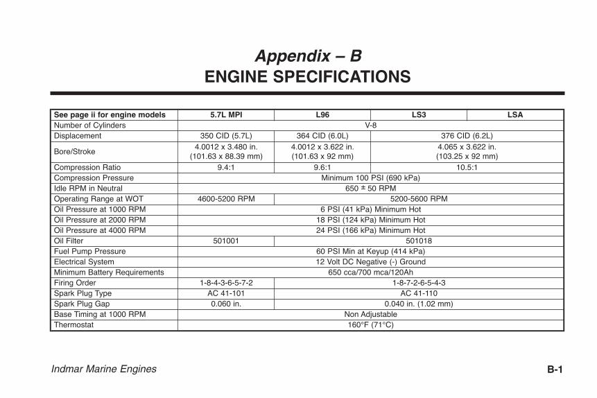
Indmar Marine Engines B-1
Appendix – BENGINE SPECIFICATIONS
See page ii for engine models 5.7L MPI L96 LS3 LSANumber of Cylinders V-8Displacement 350 CID (5.7L) 364 CID (6.0L) 376 CID (6.2L)
Bore/Stroke4.0012 x 3.480 in.
(101.63 x 88.39 mm)4.0012 x 3.622 in. (101.63 x 92 mm)
4.065 x 3.622 in.(103.25 x 92 mm)
Compression Ratio 9.4:1 9.6:1 10.5:1Compression Pressure Minimum 100 PSI (690 kPa)Idle RPM in Neutral 650 ± 50 RPMOperating Range at WOT 4600-5200 RPM 5200-5600 RPMOil Pressure at 1000 RPM 6 PSI (41 kPa) Minimum HotOil Pressure at 2000 RPM 18 PSI (124 kPa) Minimum HotOil Pressure at 4000 RPM 24 PSI (166 kPa) Minimum HotOil Filter 501001 501018Fuel Pump Pressure 60 PSI Min at Keyup (414 kPa) Electrical System 12 Volt DC Negative (-) GroundMinimum Battery Requirements 650 cca/700 mca/120AhFiring Order 1-8-7-2-6-5-4-3Spark Plug Type AC 41-110Spark Plug Gap
1-8-4-3-6-5-7-2 AC 41-1010.060 in. 0.040 in. (1.02 mm)
Base Timing at 1000 RPM Non AdjustableThermostat 160°F (71°C)
OME0502-15 Body.qxp_OM0502-05 Body.qxd 5/20/14 12:45 PM Page B-1

B-2 Indmar Marine Engines
Fluid Capacities 5.7L Carbureted 5.7L MPI L96 LS3 LSACrankcase (With Filter) 5.5 Quarts (5.25L)* 6.0 Quarts (5.7L) 8.5 Quarts (8.0L)Closed Cooling System 12-14 Quarts (11.4-13.3L)In-Line 1:1 Transmission 1.7 Quarts (1.6L) Dexron 3 ATFIn-Line Reduction Gear 2.12 Quarts (2L) 15W40ZF Ski Vee Transmission 2.12 Quarts (2L) Main Gearbox, 1.0 Quart (1.06L) V-Drive - Dexron 3Indmar-Vee Transmission 2.3 Quarts (2.12L) Main Gearbox - Dexron 3, 1.25 Quart (1.18L) V-Drive - Mobil Delvac Synthetic 50ZF 63IV Transmission 4.2 Quarts (4L) 15W40Walter V-Drive 0.5 Quart (0.5L) 15W40 Motor Oil
* The Skier’s Choice Premium 5.7L (SC350) is equipped with a special oil pan with a capacity of approximately 7 quarts (6.6L). Always fill the oil tothe “FULL” mark on the dipstick.
OME0502-15 Body.qxp_OM0502-05 Body.qxd 5/20/14 12:45 PM Page B-2

Indmar Marine Engines C-1
1. Warranty. Indmar Products Co., Inc., 5400 Old Millington Road, Millington, Tennessee 38053 (“Indmar”), warrants that its marinepropulsion engine and the parts related thereto (collectively, “Product”) are free from material defects in material and workmanshipunder normal use and service during the applicable warranty period as set forth herein.
2. Coverage. Indmar shall replace or repair any defect in material or workmanship relating to the Product under the terms and con-ditions of this Limited Product Warranty. Components or parts of the Product that Indmar determines in its sole discretion to be“wornout” from use are specifically excluded from this Limited Product Warranty. If a Product or defective part thereof is, upon exam-ination by Indmar, determined by Indmar to be defective, Indmar shall repair, or at its sole option, provide either a new or rebuiltreplacement of equivalent quality. Indmar shall have the sole discretion to determine whether the replacement, if provided, shall bea new or rebuilt replacement. Indmar’s sole obligation under this Limited Product Warranty is limited only to the foregoing obligationsas stated herein.
3. Customer. This Limited Product Warranty is extended only to the original retail purchaser of a boat or the original lessor, in thecase of a leased boat, in which a Product has been installed pursuant to Indmar’s approval or authority (“Customer”). In the eventthat the product is used in conjunction with a demonstrator or boat show display, the warranty begins from the earlier of the date ofdelivery to the retail purchaser or such time as the boat installed with the Indmar product attains more than 50 hours of use regardlessof the source of such use. If the boat is sold or traded prior to the end of the applicable warranty period set forth herein, the remainderof the applicable warranty period is transferable to the new owner or new lessor (also referred herein as “Customer”) provided thatall of the requirements for a valid transfer as set forth in this Limited Product Warranty are satisfied. No transfer of any rights by anyCustomer shall be deemed valid or effective unless and until approved in writing by Indmar. Warranties of any nature to any personother than those described herein are specifically excluded.
Appendix – CINDMAR LIMITED PRODUCT WARRANTY
GM-Based Engines
OME0502-15 Body.qxp_OM0502-05 Body.qxd 5/20/14 12:45 PM Page C-1

C-2 Indmar Marine Engines
4. Excluded Items. In addition to, and without in any way limiting, any exclusion set forth elsewhere in this Limited ProductWarranty, this Limited Product Warranty shall not apply to the following items:
(a) Shop supplies used in performing work pursuant to this Limited Product Warranty, including, but not limited to, rags, sealantsand lubricants.
(b) Incidental and consequential damages, including, but not limited to, storage charges, telephone or rental charges of any type,inconvenience or loss of time or income.
(c) Minor adjustments and tune-ups, including, but not limited to, checking, cleaning or adjusting spark plugs, filters, belts, con-trols and checking lubrication.
(d) Water pump impellers, water hoses, cooling system anodes, or any component determined solely by Indmar to be damagedfrom the failure of any of such items.
(e) Product failure as determined solely by Indmar to be caused by neglect, lack of maintenance, accident, abnormal operation,improper installation, improper preparation, improper winterization, improper dealer set-up, improper service or normal wearand tear.
(f) Haul-out, launch, and towing charges.
(g) Cost and expense incurred that relate to the removal and/or replacement of boat partitions, seating, or material due to boatdesign for necessary access to the Product.
(h) Transportation charges and travel time incurred by dealer to fulfill any of its obligations pursuant to this Limited ProductWarranty.
(i) Service or work to the Product as requested by the Customer that is as determined solely by Indmar to be beyond the scopeof this Limited Product Warranty.
(j) Use of parts other than Indmar parts (or parts authorized by Indmar) and the use of labor other than Indmar labor (or laborauthorized by Indmar) when making repairs or providing a replacement under this Limited Product Warranty.
(k) Oil, lubricants or fluids used for the normal maintenance of the Product.
(l) Defects to the Product as determined solely by Indmar to be caused by or due to participation in or preparing for racing orother competitive activity.
(m) Defects to the starter motor, armatures or field coil assembly of the Product as determined solely by Indmar to be caused byexcessive cranking, condensation or submersion.
OME0502-15 Body.qxp_OM0502-05 Body.qxd 5/20/14 12:45 PM Page C-2

Indmar Marine Engines C-3
(n) Defects to the Product as determined solely by Indmar to be caused by water entering the Product via the intake or exhaustsystem or submersion or exposure.
(o) Defects to the Product as determined solely by Indmar to be caused by the use of fuels and lubricants that are not suitablefor use with or on the Product or its fuel system components that was damaged or rendered inoperable from stale gasoline.
(p) Defects to the Product as determined solely by Indmar to be caused by the lack of cooling water resulting from the motorbeing started out of water or foreign materials blocking intake passages.
(q) Defects to the Product as determined solely by Indmar to be caused by servicing errors made by the Customer or by anyservicing dealer/mechanic not approved or authorized by Indmar.
(r) Product warranty claims that Indmar in its sole opinion determines are not due or traceable to material defects in material orworkmanship of the Product.
5. Inspection and Testing of Product. Certain parts of the Product may be tested upon receipt by Indmar. Such parts found to befree of defects will be returned to the dealer and no credit will be issued. Indmar reserves the right to retrieve run time/run conditiondata from a Product’s Electric Control Module prior to granting any warranty coverage on the Product under this Limited ProductWarranty.
6. Warranty Period. Warranty coverage shall be provided only for the periods of time hereinafter set forth:
(a) For Product installed in boats manufactured by a manufacturer approved by Indmar (OEM):
(i) A period of thirty six (36) months commencing from the date of purchase, in the case of non-commercial use;
(ii) A period of thirty six (36) months commencing from the lease date if the lease is for private use and is for a time periodof not less than two (2) years; or
(iii) A period of twelve (12) months commencing from the date of purchase or lease inception or 240 hours of Product use,whichever sooner occurs, in the case of commercial use.
(b) For repowers (defined as engines purchased for replacement) or the installation of the Product in boats by a manufacturernot approved or authorized by Indmar:
(i) A period of twelve (12) months commencing from the date of purchase or 240 hours of Product use, whichever sooneroccurs, in the case of non-commercial use; or
(ii) A period of twelve (12) months commencing from the date of purchase or 240 hours of Product use, whichever sooneroccurs, in the case of commercial use.
OME0502-15 Body.qxp_OM0502-05 Body.qxd 5/20/14 12:45 PM Page C-3
C-4 Indmar Marine Engines
In the event that more than one warranty time period may be applicable to a particular Product pursuant to this Section 6, the shortestperiod of time shall apply and shall be the only warranty time period allowed for that Product.
The repair or replacement of parts or the performance of service under this Limited Product Warranty does not extend the applicableperiod of this warranty beyond its original expiration date as set forth herein.
7. Procedure. Within 10 days from the date of purchase by the original retail purchaser of the Product or the beginning date oflease period, the Selling Dealer shall register the Product online by visiting the Indmar Dealer Portal, http://dealers.indmar.com. Inaddition to other requirements set forth herein, no warranty claim will be honored without the successful online registration of theProduct. In the case of a leased boat, a copy of the lease contract showing the length of the lease must be delivered to Indmar. In thecase of a warranty transfer to a subsequent owner or lessor, the new owner/lessor’s information along with the appropriate paymentmust be sent to Indmar by an authorized Indmar dealer within 10 days of the transfer. No transfer shall be effective or valid unlessand until approved by Indmar in its sole discretion. In the case of a warranty transfer relating to a leased boat, a copy of the leasecontract showing the length of the lease must also be submitted to Indmar by an authorized Indmar dealer along with the appropriatepayment. For warranty claims to be asserted hereunder, the Product or defective part thereof, together with a written notice of itemizeddefects must be returned to the retailer from whom the Product was purchased or to any other convenient Indmar authorized dealer.To obtain the location of an authorized Indmar dealer or service center in your area, visit the dealer locator at www.indmar.com. Inthe event that the local authorized Indmar dealer is unable to remedy a warranted defect in the Product, the Product or defective partthereof, together with a written notice of itemized defects, must be delivered to Indmar at 5400 Old Millington Road, Millington,Tennessee 38053 with any and all freight and insurance charges prepaid. All insurance and freight charges and return chargesincurred by Indmar for delivery of the Product (or its new or rebuilt replacement) to the retail purchaser or lessor shall be paid by suchpurchaser or lessor. The Customer shall be solely responsible for any and all labor expenses related to the repair or replacement ofa Product pursuant to this Limited Product Warranty that exceed the specified services rates of Indmar in effect at the date of purchaseor lease. A schedule of service rates of Indmar may be obtained from any authorized Indmar dealer.
8. Trade Accessories. Indmar makes no warranty of any character with respect to any and all trade accessories not manufacturedby Indmar.
9. Voiding the Warranty. In addition to any requirement set forth in this Limited Product Warranty not being met or satisfied, thisLimited Product Warranty shall become void and shall not apply under the following conditions or circumstances:
(a) When the Product or any part thereof is subject to accident, alternation, modifications, abuse, misuse, neglect or impropermaintenance and Indmar in its sole discretion determines the same;
(b) When the Product is serviced by any individual or entity not authorized or approved by Indmar; or
OME0502-15 Body.qxp_OM0502-05 Body.qxd 5/20/14 12:45 PM Page C-4

Indmar Marine Engines C-5
(c) When damage to the Product results from cases not arising from defects in material and/or workmanship and Indmar in itssole discretion determines the same.
10. Notices. Any notice to Indmar set forth pursuant to this Limited Product Warranty shall be delivered to the following address:
Indmar Products Co., Inc. 5400 Old Millington Road Millington, Tennessee 38053
THE WARRANTY STATED ABOVE IS A LIMITED WARRANTY AND IT IS THE ONLY WARRANTY MADE BY INDMAR. INDMARDOES NOT MAKE ANY OTHER WARRANTIES EXPRESS OR IMPLIED. THERE ARE EXPRESSLY EXCLUDED ALL WARRANTIES OF MERCHANTABILITY AND FITNESS FOR A PARTICULAR PURPOSE. INDMAR SHALL HAVE NO LIABILITYWITH RESPECT TO ITS OBLIGATIONS UNDER THIS LIMITED WARRANTY OR OTHERWISE FOR CONSEQUENTIAL, EXEMPLARY, INCIDENTAL OR PUNITIVE DAMAGES EVEN IF IT HAS BEEN ADVISED OF THE POSSIBILITY OF SUCH DAM-AGES. THE STATED EXPRESS LIMITED WARRANTY IS IN LIEU OF ALL LIABILITIES OR OBLIGATIONS OF INDMAR FORDAMAGES ARISING OUT OF OR IN CONNECTION WITH THE DEVELOPMENT, DELIVERY, USE OR PERFORMANCE OFTHE PRODUCT. IN ANY EVENT, THE LIABILITY OF INDMAR FOR ANY REASON AND UPON ANY CAUSE OF ACTION WHAT-SOEVER SHALL BE LIMITED TO THE AMOUNT THEN PREVIOUSLY PAID FOR THE PRODUCT BY THE CUSTOMER.
INDMAR DOES NOT AUTHORIZE ANY PERSON, EMPLOYEE, AGENT, REPRESENTATIVE OR ENTITY TO ALTER ANY OFTHE TERMS AND CONDITIONS OF THIS LIMITED PRODUCT WARRANTY OR CREATE ANY OTHER OBLIGATION RELAT-ING TO THE PRODUCT. THIS WARRANTY GIVES YOU SPECIFIC LEGAL RIGHTS, AND YOU MAY ALSO HAVE OTHERRIGHTS WHICH MAY VARY FROM STATE TO STATE.
NOTICE TO CALIFORNIA CUSTOMERS: CALIFORNIA CUSTOMERS MUST DIRECTLY NOTIFY INDMAR IN WRITING IF THEPRODUCT DOES NOT CONFORM TO APPLICABLE WARRANTIES AND (A) THE NON-CONFORMITY IS LIKELY TO CAUSEDEATH OR SERIOUS BODILY INJURY AND HAS BEEN SUBJECT TO REPAIR TWO (2) OR MORE TIMES, AND/OR (B) THENON-CONFORMITY HAS BEEN SUBJECT TO REPAIR FOUR (4) OR MORE TIMES. CALIFORNIA CUSTOMERS ARE HERE-BY NOTIFIED TO THE FOLLOWING PROVISIONS OF CALIFORNIA LAW: CAL. CIVIL CODE § 1793.22 AND CAL. CIVIL CODE§ 1793.2(d). COMPLETE COPIES OF THESE CODE SECTIONS ARE AVAILABLE UPON REQUEST.
OME0502-15 Body.qxp_OM0502-05 Body.qxd 5/20/14 12:45 PM Page C-5

C-6 Indmar Marine Engines
INTERNATIONAL WARRANTY EXCLUSIONS
In addition to the limited warranty statement, the following limitations apply to products sold outside of the United Statesand Canada.
Indmar is not responsible for any Indmar Marine Engine Package:
(a) Sold through an unauthorized dealer or OEM
(b) Installed by an unauthorized dealer or OEM
(c) Imported into the country by an individual or unauthorized OEM or dealer
(d) That has not been properly serviced and maintained as stated in the Indmar Operator’s Manual
(e) Customs charges, import duties, taxes and VAT on warranty replacement parts
INTERNATIONAL WARRANTY PROCEDURES
Indmar is excited to expand internationally with our boat builder partners and continually stands behind and supports itspower packages that are sold outside the United States and Canada. To provide this support, Indmar Marine engineswould like to ask international customers to help us provide the best quality customer service by adhering to all respon-sibilities that our North American owners comply with as outlined in this warranty. This, in addition to understanding theimportance of service and maintenance through an authorized Indmar dealer or OEM, will help ensure that you theowner will receive the best quality workmanship and care of your new Indmar power package.
OME0502-15 Body.qxp_OM0502-05 Body.qxd 5/20/14 12:45 PM Page C-6

PROPOSITION 65
The engine exhaust from this product contains chemicals known to the State of California to cause cancer, birthdefects or other reproductive harm.
WARNING
Date of Purchase: ______________________ Owner Name: _____________________________________________
Address: __________________________________________________ City: ________________________________
State/Province: ___________________________ Zip/Postal Code:____________ Country: ____________________
Engine Serial Number: _____________________________ Transmission Serial Number:_______________________
10-20 Hour ServiceDate:___________ Hours:____________By:_______________________________
Every 50 (25) Hour ServiceDate:___________ Hours:____________By:_______________________________
Date:___________ Hours:____________By:_______________________________
Date:___________ Hours:____________By:_______________________________
Date:___________ Hours:____________By:_______________________________
Date:___________ Hours:____________By:_______________________________
Date:___________ Hours:____________By:_______________________________
Date:___________ Hours:____________By:_______________________________
Date:___________ Hours:____________By:_______________________________
Every 100 Hour ServiceDate:___________ Hours:____________By:_______________________________
Date:___________ Hours:____________By:_______________________________
Date:___________ Hours:____________By:_______________________________
Date:___________ Hours:____________By:_______________________________
Date:___________ Hours:____________By:_______________________________
Date:___________ Hours:____________By:_______________________________
Date:___________ Hours:____________By:_______________________________
Date:___________ Hours:____________By:_______________________________
Date:___________ Hours:____________By:_______________________________
Every 300 Hour/Annual ServiceDate:___________ Hours:____________By:_______________________________
Date:___________ Hours:____________By:_______________________________
Date:___________ Hours:____________By:_______________________________
Date:___________ Hours:____________By:_______________________________
Date:___________ Hours:____________By:_______________________________
Date:___________ Hours:____________By:_______________________________
Every 2 Year ServiceDate:___________ Hours:____________By:_______________________________
Date:___________ Hours:____________By:_______________________________
Date:___________ Hours:____________By:_______________________________
OME0502-15 Cover.qxp_OM0502-05 Cover.qxd 4/28/14 10:27 AM Page 2

Operator’s ManualPart No. OME0502-15 Printed in U.S.A.
The first production inboard equipped with catalytic converters.
Ken Cook Co.
5400 Old Millington Road Millington, TN 38053
www.indmar.com
OME0502-15 Cover.qxp_OM0502-05 Cover.qxd 4/28/14 10:27 AM Page 1