HYDRAULIC CYLINDER FOR INBOARD ENGINES UC 378
24
Installation and Maintenance Manual HYDRAULIC CYLINDER FOR INBOARD ENGINES UC 378 (Dr. No. 23735/c 08/05/2015) SOCIO
Transcript of HYDRAULIC CYLINDER FOR INBOARD ENGINES UC 378

Installation and Maintenance ManualHYDRAULIC CYLINDER FOR
INBOARD ENGINES
UC 378
(Dr. No. 23735/c 08/05/2015)
SOCIO

Dear Customer,
We would like to thank you for choosing an ULTRAFLEX SpA product.
ULTRAFLEX SpA has been a leader in steering systems for pleasure and professional boats for manyyears.
All ULTRAFLEX SpA products are designed and manufactured to ensure the best performance.To ensure your safety and to maintain a high quality level, ULTRAFLEX SpA products are guaranteed onlyif they are used with original spare parts (see attached document "Application Spare Parts").
ULTRAFLEX SpA and Quality Management System is certified CISQ-IQNet by the Italian Shipping Registry(RINA), in conformity with the UNI EN ISO 9001:2000 rule. ULTRAFLEX SpA certification No. 6669/02/S (former420/96).
The quality management system involves all the company resources and processes starting from thedesign, in order to:- ensure product quality to the customer;- maintain and improve the quality standards constantly;- pursue a continuous process improvement to meet the market needs and to increase the customer
satisfaction;- constantly test the products to verify their conformity with the 2013/53/EU.
"Established in 1989 UFLEX USA is a leader in steering and control systems for the marine industry.With full manufacturing capabilities in Sarasota, Florida, UFLEX USA can support all sectors of the marineindustry regardless of volume and/or product requirements. And, as an affliate of the ULTRAFLEX Group,UFLEX USA has tremendous resources to draw upon for new product development in hydraulics, electronicsand many other technologies.
Innovative product design and unparalleled dedication to quality customer service and products conti-nue to be cornerstone of UFLEX USA's growth. Today our products can be found as originally installedequipment on many of the most widely known and respected boat brands in the world.Aftermarket parts can be sourced from trained and experienced distributor network troughout Northand South America.
Our dedication to providing the highest quality products and service is only matched by our commitmentto developing new products employing the lastest materials and technology to enhance our customer'sboating experience. From steering wheels to sophisticated electronic controls, UFLEX USA has everythingyou need to make sure that your boat looks and perform it's best for many, many years."
UFLEX USASarasota, FL 34243 - 6442 Parkland Drive

HYDRAULIC CYLINDER FOR INBOARD ENGINE - page 3 of 24
Installation and Maintenance Manual
SECTION 1 - PRODUCT DESCRIPTION1.1 HYDRAULIC STEERING SYSTEM OPERATION..................................................................................71.2 WARNINGS FOR THE CORRECT PRODUCT USE ......................................................................71.3 SYSTEM CONFIGURATIONS.........................................................................................................................81.4 CYLINDER DESCRIPTION..............................................................................................................91.5 TECHNICAL FEATURES..........................................................................................................................9
TABLE OF CONTENTS
SECTION 2 - TRANSPORT2.1 GENERAL WARNINGS.............................................................................................................................102.2 PACKAGING CONTENTS....................................................................................................................10
SECTION 5 - MAINTENANCE5.1 ORDINARY MAINTENANCE.................................................................................................................195.2 TROUBLESHOOTING.........................................................................................................................19
SECTION 3 - INSTALLATION3.1 NECESSARY TOOLS..................................................................................................................113.2 CYLINDER INSTALLATION.......................................................................................................................113,3 HOSE INSTALLATION...............................................................................................................133,4 TYPE OF INSTALLATION.........................................................................................................................143.5 FILLING AND PURGING.......................................................................................................................153,5,1 SINGLE STEERING STATION/ SINGLE CYLINDER.......................................................................................163.5.2 DUAL STEERING STATION/SINGLE CYLINDER.........................................................................................173.6 GENERAL RECOMMENDATIONS................................................................................................................17
SECTION 4 - SAFETY WARNINGS4.1 SAFETY WARNINGS DURING USE AND INSTALLATION ........................................................................184.2 CLOTHING....... . . . . . . . . . . . . . . . . . . . . . . . . . . . . . . . . . . . . . . . . . . . . . . . . . . . . . . . . . . . . . . . . . . . . . . . . . . . . . . . . . . . . . . . . . . . . . . . . . . . . . . . . . . . . .18
SECTION 6 - DISMANTLING6.1 DISMANTLING........................................................................................................................21
!
MANUAL USE AND SYMBOLS USED................................................................................................................4INTRODUCTION.................................................................................................................................5WARRANTY... .. .. .. .. ... .. .. .. ... .. .. .. ... .. .. .. .. ... .. .. .. ... .. .. .. ... .. .. .. .. ... .. .. .. ... .. .. .. .. ... .. .. .. ... .. .. .. ... .. .. .. .. ... .. .. .. .5

Installation and Maintenance Manual
page 4 of 24 - HYDRAULIC CYLINDER FOR INBOARD ENGINE
In this manual the following symbols are used to ensure the user safety and to guarantee the correctoperation of the product:
MANUAL USE AND SYMBOLS USEDTHE INSTALLATION AND MAINTENANCE MANUAL is the document accompanying the product from its saleto its replacement and discharge. The manual is an important part of the product itself.It is necessary to read carefully the manual, before ANY ACTIVITY involving the product, handling andunloading included.
STERN
BOW
STARBOARD PORT The picture aside explains the meaning of somenautical words contained in this manual.
DANGER Immediate hazards which CAUSE severe personal injury or death.
WARNING
CAUTION
The symbol aside indicates all the operations which must be carried outby qualified or skilled staff, in order to avoid hazards.We recommend training the staff in charge of the product installationand checking their knowledge.
NOTICE Important information for the correct installation and for maintenance, thatdoes not cause any damage.
Denotes that a hazard exists which can result in injury or death if properprecautions are not taken.
Denotes a reminder of safety practices or directs attention to unsafepractices which could result in personal injury or damage to the craft orcomponents or to the environment.
HYDRAULIC CYLINDER FOR INBOARD ENGINE - page 5 of 24
Installation and Maintenance Manual
TECHNICAL ASSISTANCE SERVICE
INTRODUCTION
U F L E X S .r.l.Via Milite Ignoto,8A16012 Busalla (GE)-ItalyPh.: +39.010.962.0239 (Italy)Ph.: +39.010.962.0244 (abroad)Fax: +39.010.962.0333Email: [email protected]
North - South - Central America:U F LE X USA6442 Parkland DriveSarasota, FL 34243Ph.: +1.941.351.2628Fax: +1.941.360.9171Email: [email protected]
This installation and maintenance manual represents an important part of the product and must be availableto the people in charge of its use and maintenance.The user must know the content of this manual.UFLEX USA declines all responsibility for possible mistakes in this manual due to printing errors.Apart from the essential features of the described product, UFLEX USA reserves the right to make thosemodifications, such as descriptions, details and illustrations, that are considered to be suitable for itsimprovement, or for design or sales requirements, at any moment and without being obliged to update thispublication.ALL RIGHTS ARE RESERVED. Publishing rights, trademarks, part numbers and photographs of UFLEX USAproducts contained in this manual are UFLEX USA property.Great care has been taken in collecting and checking the documentation contained in this manual tomake it as complete and comprehensible as possible. Nothing contained in this manual can be interpretedas warranty either expressed or implied - including, not in a restricted way, the suitability warranty for anyspecial purpose. Nothing contained in this manual can be interpreted as a modification or confirmation ofthe terms of any purchase contract.
To ensure the correct product and component operation, the product must be installed by qualified staff.In case of part damage or malfunction, please contact the qualified staff or our Technical AssistanceService.
WARNING
WARRANTY1. Two Year Limited Warranty. UFLEX USA, Inc. warrants that all products manufactured by UFLEX USA,
Inc. or ULTRAFLEX S.p.A. and sold by UFLEX USA to the retail purchaser ("Purchaser") that for two (2) yearsafter the date of manufacture to be free from defects due to material or workmanship, subject to theexclusions below. Improper installation AVOIDS this warranty. Installation should only be attempeted bya trained and qualified technician.
2. Exclusions. This limited warranty does not cover and does not extend to any of the following:(a) Failure caused by normal wear and tear, climatic conditions, misure, neglect, lack of propermaintenance, accident, fire or other casualty damage, racing, overloading, negligence, modification,beaching or grounding of vessel, collision, impact, towing, acts of war or hostilities;(b) components not manufactured by UFLEX USA, Inc., or its affiliates;(c) cost of removal or reinstallation of any component (including components manufactured by UFLEXUSA, Inc.) or disassembly or reassembly of the unit containing the component;(d) components not manufactured by UFLEX USA, Inc. or ULTRAFLEX S.p.A., whether or not warranted bythe other manufacturer;(e) any product which has not been properly installed.

Installation and Maintenance Manual
page 6 of 24 - HYDRAULIC CYLINDER FOR INBOARD ENGINE
3. Limitations. THE REPAIR OR REPLACEMENT OF DEFECTIVE PARTS SHALL BE PURCHASER'S SOLE ANDEXCLUSIVE REMEDY AND UFLEX USA, INC,'S SOLE AND EXCLUSIVE LIABILITY UNDER THIS WARRANTY.LABOR FOR REPLACEMENT IS NOT INCLUDED. UFLEX USA, Inc.'s obligation under this warranty is limitedto the repair or replacement (at UFLEX USA, Inc.'s sole election) of any covered item found to be defective,when delivered by Purchaser pursuant to written authorization and instructions from UFLEX USA, Inc.,shipping prepaid to UFLEX USA, Inc.'s plant or other designated repair facility. Repaired or replaceditems are warranted as provided herein for the unexpired portion of the applicable warranty period.THIS WARRANTY, AND THE RIGHTS AND REMEDIES UNDER IT, IS EXCLUSIVE AND IS GIVEN IN PLACE OFALL OTHER WARRANTIES, WHETHER EXPRESS OR IMPLIED, INCLUDING ANY IMPLIED WARRANTY OFMERCHANTABILITY OR FITNESS FOR PARTICULAR PURPOSE, WHETHER ARISING BY LAW, CUSTOM,CONDUCT OR USAGE OF TRADE, PURCHASER'S REMEDIES SHALL BE LIMITED AS STATED HEREIN ANDUFLEX USA, INC. SHALL NOT BE LIABLE FOR ANY INCIDENTAL, CONSEQUENTIAL OR INDIRECT DAMAGESOR LOSSES RESULTING FROM DEFECTS. THE RETAIL SELLER IS NOT A CO-WARRANTOR AND IS NOTAUTHORIZED BY UFLEX USA, INC. TO AMEND OR MODIFY THIS LIMITED WARRANTY IN ANY MANNER.
4. Transferability of Warranty. This limited warranty may not be transferred to subsequent purchasers.
5. Miscellaneous. UFLEX USA, Inc. is an affiliate of ULTRAFLEX S.p.A. UFLEX, USA, Inc., reserves the right tomake changes in the design and construction of its products at any time, without notice and without anyobligation to incorporate such changes into products of prior manufacture. This limited warranty appliesto new components sold by UFLEX USA, Inc.. This limited warranty contains the entire agreements betweenUFLEX USA, Inc. and Purchaser and suspersedes all prior agreements, discussions, negotiations,commitments and representations, whether oral or written, between them regarding UFLEX USA, Inc'swarranty. If any provision of this limited warranty, or the application of it, is determined to be invalid ofunenforceable for any reason, the remainder of this limited warranty and the application of it shall notbe affected.
6. Ultron 3000 and PowerC. The Ultron 3000 and "PowerC - User and Installation Manual" describesactivities, operations, technical specifications which must be followed during the installation and/orusage of the product, in order to keep a valid warranty. Descriptions and drawings in that manual aresuitable to allow installation and use of the product to skilled persons. In case of doubt and/or for anyinformation, please contact our Technical Service.
All communications and notices from Purchaser regarding this limited warranty should be sent to: UFLEXUSA, INC., 6442 Parkland Drive, Sarasota, FL 34243; (941) 351-2628.
Return policy
Any product that is presumed defective should be reported to UFLEX USA within 48 hours of receipt ordiscovery in the field. Upon notification UFLEX USA will attempt to troubleshoot the problem with our customerover the phone. If we are unable to resolve the problem UFLEX will issue a Return Goods Authorizationnumber and we require that the product in question be returned to UFLEX with all its parts in its originalpackaging. The product should be returned freight prepaid to:
UFLEX USARGA Department - RGA #6442 Parkland DriveSarasota, Florida 34243
Upon receipt UFLEX will examine the product to determine the cause of the defect. If the product is determinedto have a defect in workmanship or material, it will be repaired at our discretion.
Our warranty does not cover labor, towing or other expenses. Further, it does not cover products that havebeen improperly installed, damaged in installation, misapplied, or misused.
Our products are not intended for use in racing applications.

HYDRAULIC CYLINDER FOR INBOARD ENGINE - page 7 of 24
Installation and Maintenance Manual
The UC 378 cylinder must not be installed on race boats.
In dual helm applications horsepower must not exceed 450hp and boat speed must not exceed 55 m.p.h.
All UFLEX steering systems must not be installed on boats equipped with engines whose maximum horsepoweris higher than the horsepower rating approved by boat manufacturer.
1.2 Warnings for the product correct use
Do not modify the steering cylinder in any way to fit it to your application, otherwise the cylinder will nolonger operate in safety and it will endanger the boat and the occupants.
WARNING
WARNING
WARNING
DANGER
1 PRODUCT DESCRIPTION1.1 Hydraulic steering system operationAll UFLEX hydraulic steering systems are designed in conformity with UNI-EN-ISO 10592 and A.B.Y.C. P21regulations. All UFLEX steering systems can operate at temperatures between -18°C (0°F) and +77°C (+170°F).All the components are made for the marine environment, using materials and working processes whichoffer long life and safety under the most extreme conditions. A hydraulic steering system consists of asteering pump, a cylinder tied to the rudder or to the outboard orsterndrive engine and the connecting hoses (see picture). Under normaloperating conditions, a turn of the steering wheel will pump the oil,which flows in through the hoses to the cylinder, according to the turndirection. With the consequent cylinder movement the oil will flow to thepump through the hoses and at the same time moves the engine or thehelm which are connected to the cylinder. The pumps equipped with avalve which prevents outgoing fluid from returning along the same hose,allow the operation of the steering systems with two or more steeringstations. The cylinders are double acting and may be balanced orunbalanced. In the unbalanced cylinders the two chambers have differentvolumes and so they need a different number of turns of the steeringwheel and a different rotation effort. The balanced cylinders have samenumber of steering wheel turns in order to move the helm from thecenter to the end stroke in the two opposite directions. A well balancedsteering system needs a correct choice of the pump for the cylinder.UFLEX produces different pump models, which have different capacity (cm3 of oil moved each steering wheelturn) and for each type of installation. While choosing the pump it is important to consider the cylindervolume. The number of starboard and port turns is determined by the ratio between the cylinder volumeand the pump capacity.Example: if the pump has a capacity of 28 cm3 [1,7cu.in.] and the cylinder has a volume of 120 cm3 [7,3cu.in.], theformula looks like this: 120/28=4,2. Accordingly, the steering wheel will turn 4,2 times before the cylinderwill completely turn from one side to the other. In case of installations with double cylinders connected inparallel the cylinder volume must be added. Applications with less than 4 turns are not recommended, asthey need a higher effort, also applications with more than 8 turns are also not recommended, as theresponse of the boat to steer is slowly.
pump
ll
hydraulic hosel
cylinder
helm
l

Installation and Maintenance Manual
page 8 of 24 - HYDRAULIC CYLINDER FOR INBOARD ENGINE
1.3 System configurationsThe hydraulic cylinder for inboard engine UC 378 model can be installed with different configurations accordingto the number and the type of engines used with a single or dual engine steering system.The possible configurations are:
STEERING STATIONNUMBER
SINGLE
STATION
HELM NUMBER
With SINGLE CYLINDER
up to 300hp max
MAIN STATION
ADDITIONALSTATION
DUAL
STATION
SINGLE
HELM
NOTICEDual engine installations require the use of a tie bar.Dual station installations require the use of 2 helms with non-return valve.
With SINGLE CYLINDER and TIE BAR
non-counter rotatingengines up to300 hp max ofcombined horsepower
counter rotatingengines up to 450 hpmax of combinedhorsepower and up to55 m.p.h.
DUAL
HELM

HYDRAULIC CYLINDER FOR INBOARD ENGINE - page 9 of 24
Installation and Maintenance Manual
1.4 Cylinder descriptionUC 378 is a hydraulic inboard cylinder which has been designed and manufactured to be used as a componentin the hydraulic steering systems, as described in the previous paragraph.The cylinder with mobile rod is installed directly to the arm of the helm through the proper ball joint on theend part of the cylinder. On the opposite side it is fixed directly to the boat through a support with plate (seepar. 3.2). For the dual helm application, the single cylinder must be mounted with a tie bar (see par. 1.3).The following picture shows the main cylinder components:
Overall dimensions:
∅ 15,875 mm [5/8 in.]
19,0
5 m
m [
3/4
in.]
45 m
m [
1,77
in.]
100
mm
[3,
93 in
.]
19,0
5 m
m [
3/4
in.]
717 mm [28,22 in.]
60 mm[2,3 in.]
145
mm
[5,7
0 in
.]
1.5 Technical features
Cylinder body
Bleeders
Ball joint
Support with mounting brackets
Rod
1
2
3
4
2
1
43
5 5
SPECIFICATIONS UC 378Volume 376 cc - 23 cu. inOutput force 1177 kg - 2595 Ibs (@70 bar)Torque 187.6 Kg/m - 16347 lbs/in. (@70 bar)Inside diameter 50 mm - 1.96"Stroke 228 mm - 8.97"Oil In compliance with ISO VG 15 OIL15

Installation and Maintenance Manual
page 10 of 24 - HYDRAULIC CYLINDER FOR INBOARD ENGINE
2.1 General warnings2 TRANSPORT
The product weight with its packaging is 9kg (19 pounds) and so it can be handled manually.
2.2 Packaging contentsBefore using the equipment check that the product has not been damaged during transport.Also make sure that all the standard components are in the packaging (see list). In case of damage,notify the claim to the forwarder and inform the supplier.
WARNING
The staff in charge of handling must operate with protective gloves and safety shoes.
The packaging must be disposed of according to the existing laws.
CAUTION
A
A) CylinderB) 2 flexible hoses for cylinder-system connectionC) 2 fittings for flexible hose-system connection with a 12mm (0,5") hose.
B
C
HYDRAULIC CYLINDER FOR INBOARD ENGINE - page 11 of 24
Installation and Maintenance Manual
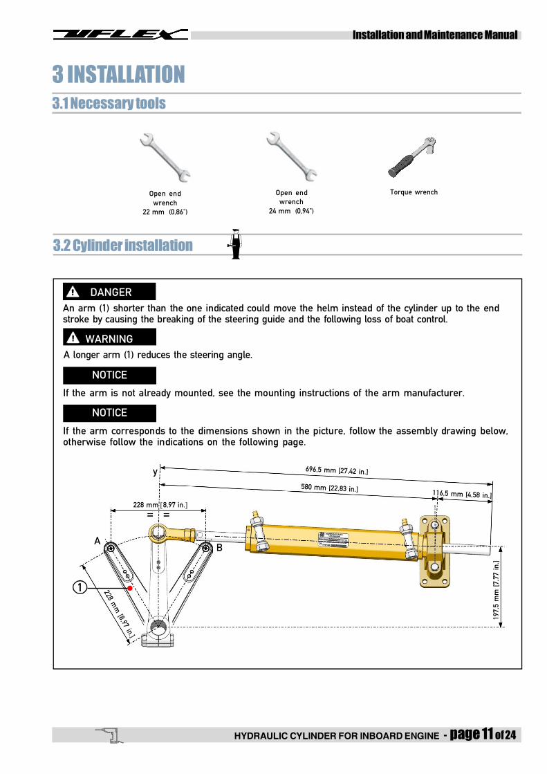
3.2 Cylinder installation
WARNINGA longer arm (1) reduces the steering angle.
If the arm is not already mounted, see the mounting instructions of the arm manufacturer.
DANGERAn arm (1) shorter than the one indicated could move the helm instead of the cylinder up to the endstroke by causing the breaking of the steering guide and the following loss of boat control.
NOTICE
3 INSTALLATION3.1 Necessary tools
If the arm corresponds to the dimensions shown in the picture, follow the assembly drawing below,otherwise follow the indications on the following page.
NOTICE
y
AB
l1
228 mm [8,97 in.]
228 mm
[8,97 in.]
696,5 mm [27,42 in.]
580 mm [22,83 in.] 116,5 mm [4,58 in.]19
7,5
mm
[7,
77 in
.]
Open endwrench
22 mm (0,86")
Torque wrenchOpen endwrench
24 mm (0,94")

Installation and Maintenance Manual
page 12 of 24 - HYDRAULIC CYLINDER FOR INBOARD ENGINE
1 Check if the arm(1) and the helmblade (2) are aligned,then center them tothe longitudinal axis.
2 Mount it by looking for the "x" imaginary line parallel tothe transom. It joins the arm hole in the two "A" and "B" endstroke positions of the cylinder when the angles between thetwo "A" and "B" positions and the "y" longitudinal axis are thesame ones. This line will be the mounting axis of the cylinder.
1
l
l2 x
A B
y= =
Check if the cylinder in the two "A" and "B" end stroke positions is aligned in horizontal position (parallelto the transom). Move the helm forward and backward in order to check the free movement of thecylinder and if these positions are perfectly symmetrical to the "y" axis as shown in picture 2.Be sure the movement of the ball joints is not hindered.
Check if the cylinder and not the helm moves up to the end stroke.
In case of connection of the two helms with tie bar, the cylinder can be connected directly to the tie baror to one of the helm arms; follow the instructions given with the arms and/or with the tie bar.
DANGER
CAUTION
3 Check if the "z" axis of the bracket (3) isperpendicular to the"x" axis of the cylinder. Fixthe bracket (3) on a proper support with 4 screwsdiam. 8 mm (5/16") and 4 stainless steel self-locking nuts fit to bear the forces at stake (screwsand nuts are not supplied).
The oil fittings must be always in high position.
NOTICE
4 Connect the joint (4) to the arm (1); the armmust be under the joint; (follow the instructionsof the arm manufacturer).
WARNINGThe ball joint (4) must belocked by means of thesafety lock nut (5) with atorque of 100±10Nm(73.8±7.38 lb-ft) (22mm-0.86" wrenches and24mm -0.94" wrenches).
Fine adjustmentmust not exceed thevalue shown in thepicture.
l4
l
1
l
5
WARNING
l3
x
z
60 mm[2,36 in.]
145
mm
[5,7
0 in
.]
�
22mm [0.86"] max.
l
4 l
5

HYDRAULIC CYLINDER FOR INBOARD ENGINE - page 13 of 24
Installation and Maintenance Manual
3.3 Hose installationThe two fittings mounted on the cylinder body are already oriented and are ready to be used.
DANGER
NO
WARNING
An excessive hose bend could result in its internal breaking whichwill cause a bad operation of the system. In this case it is necessary toreplace the damaged hose.
The fittings mounted on the cylinder cannot be oriented. If they areunscrewed, they could be broken and the cylinder is no more usable.
NOTICE
The installation of the rigid tubes (4) (cutting, bending androuting) must be carried out by specialized staff by following the instructions of the manufacturer.If copper or steel tubes are used, rinsing is required.
YES
Connect the flexible hoses supplied (1) to the cylinder andto the fittings supplied (2) by tightening the nuts with ogi-ve (3) by means of an open end wrench 22 mm (0.86")with a torque of 45-50 Nm (33.2-36.9 lb-ft).Connect the rigid tubes (4) to the pump (2) and to the fittings(2) in the same way.
2
1
1
3
34

Installation and Maintenance Manual
page 14 of 24 - HYDRAULIC CYLINDER FOR INBOARD ENGINE
The UC 378 hydraulic cylinder for inboard engines can be installed with different configurations according to thenumber and the type of engines used with a single or dual steering system. The possible configurations are:
3.4 Type of installation
CAUTIONConnect hoses as shown in the following pictures:
NOTICE
With reference to the boat, the hose which is connected to the port side (P) of the pump must be alwaysconnected to the fitting of the side port (P), while the hose which is connected to the starboard side (S) of thepump must be connected to the fitting of the starboard side (S),
DUAL STATION / SINGLE CYLINDERWITH DUAL HELM:
DUAL STATION / SINGLE CYLINDER:
SINGLE STATION / SINGLE CYLINDER: SINGLE STATION / SINGLE CYLINDERWITH DUAL HELM:
1. steering station2. cylinder3. T" fittings with bleed valves4. fittings supplied5. flexible hoses suuplied
1. steering station2. cylinder3. T" fittings with bleed valves4. fittings supplied5. flexible hoses suuplied6. tie bar
1. main steering station2. additional steering
station3. cylinder4. "T" fittings with bleed
valves
5. fittings supplied6. flexible hoses
supplied7. kit 120U-2S
1. main steering station2. additional steering
station3. cylinder4. "T" fittings with bleed
valves
5. fittings supplied6. flexible hoses
supplied7. kit 120U-2S8. tie bar
2
l
1l
l
l
3S
S
P
P
4
lULTRAFLEXPUMP
5l
l
1l
2
l
36
l PP
S
Sl
l
5
l
l 4
l
1
23
4l
l
l
l
l
7
l
S
S
S
P
P
P
l
l
l
l 5
l
l6
1
2l
l
l
l
8
l
4
l
l
7
3
SPS
S
P
P6
l
5
l
l
l
l
l

HYDRAULIC CYLINDER FOR INBOARD ENGINE - page 15 of 24
Installation and Maintenance Manual
3.5 Filling and purgingAfter the first installation and after maintenance operations it is necessary to fill the system with hydraulicoil. This operation must avoid the air in the system, to ensure the good system operation.The hydraulic system must be filled from the highest point of the system, which means from the uppersteering station.
CAUTION
In the days after the filling, check the oil level; if necessary top off the system.At the beginning the oil level can lower, as small amounts of air can be released in a homogeneous way.According to the types of installation, it is necessary to carry out the different bleeding procedures, as itfollows.
WARNING
To avoid air bubbles in the oil, it is necessary to fill the tank slowly.
The filling and bleeding operations must be carried out at least by two operators.
DANGERUse UFLEX oil or other compatible oils.
COMPATIBLE OILSAGIP OSO 15
MOBIL DTE 11MSHELL TELLUS T15
ESSO NUTO H15Q8 HAYDN 15
Viscosity at 100°C 3.3 cStViscosity index 96Flash point V.A. 190°CYield point -30°CVolumic mass 15° 0.860 kg/l
TECHNICAL FEATURES

Installation and Maintenance Manual
page 16 of 24 - HYDRAULIC CYLINDER FOR INBOARD ENGINE
3.5.1 Single steering station/ single cylinder1
NOTA
3
4
2
- Unscrew the two bleed valves and manually push the cylinder body toone side until it stops as shown in picture 1.
- Position the oil bottle as explained in the picture.
- Close the bleed valve on the cylinder end stroke side and put a purgedoil tank near the other bleed valve (as shown in picture 2).
- Turn the steering wheel slowly (as shown in picture 2) so that the oil cancome out of hoses,
- When the oil comes out of the bleed valve (without air bubbles), close thebleed valve and continue to turn the steering wheel in the same directionto fill the cylinder chamber (picture 3).During this phase the cylinder body will move to the opposite direction upto the end stroke.
NOTICEHold the cylinder body with the hand to prevent movements caused by theair present in the cylinder chamber (picture 2).
- Open the other bleed valve and move purged oil tank to the other side.Holding the cylinder body in this position, turn the steering wheel asshown in picture 4, until oil without air bubbles comes out of the bleedvalve.Then close the bleed valve.
- Repeat the entire procedure to ensure the absence of air in the system.

HYDRAULIC CYLINDER FOR INBOARD ENGINE - page 17 of 24
Installation and Maintenance Manual
3.5.2 Dual steering station/ single cylinder
- Repeat the procedure at least 3 times to ensure the absence of air in the system.
WARNING
WARNING
For the (lower) additional steering station tank use only the non-vent plug (supplied with the "kit 120U-2S").For the (upper) main steering station tank use only the vent plug.
- Manually unscrew the two bleed valveson the cylinder "T" fittings and push thecylinder up to the end stroke.
- Position the oil bottle near the (upper)main steering station according to whatis previously described.
Wait until the oil reaches the lower tank andboth tanks are filled.
- Follow the same bleeding proceduredescribed in paragraph 3.5 starting fromthe lower station and repeat it for theupper station.
3.6 General recommendation
It is very important to check the absence of air in the system before using the boat! We recommend tryingto manually move the engine towards port and starboard, making sure that there is no movement of thecylinder body on the main cylinder shaft.If the cylinder body moves more than 1/6 inches (15mm), there is still air in the system. The air presence inthe system can cause bad responses to the controls and so it can cause damage, injuries or death.
WARNING
l
l
l
lvent plug
non-vent plug

Installation and Maintenance Manual
page 18 of 24 - HYDRAULIC CYLINDER FOR INBOARD ENGINE !
ATTENZIONE
4 SAFETY WARNINGSThis section shows the safety rules which must be followed for the correct equipment operation.We recommend reading carefully this section and also the other manuals supplied with the steering systemcomponents.
4.1 Safety warnings during use and installationRESPECT STRICTLY the following safety rules:UFLEX declines all responsibility in case the user does not follow these rules and it is not responsible fornegligence during the use of the system.
- DO NOT PUT HANDS BETWEEN THE MOVING PARTS.- Do not disable the safety devices.- Do not modify or add devices to the system, without UFLEX written authorisation or technical
intervention which will prove the modification.- Do not use the equipment for a purpose different from the one it has been designed for, which is
specified in the installation and maintenance manual.- Do not let non-specialized staff perform the installation.- Do not disassemble the hydraulic connections before bleeding the oil in the system completely.
The hoses can contain high pressure oil.
DANGER
WARNING
- Do not put the feet on the cylinder.- Check the system after the installation and the purging but before operating the vessel. Turn the
steering wheel until the cylinder/s reaches/reach the end stroke.Turn the steering wheel to the opposite direction. Repeat on each installed helm to verify thecorrect installation and the system operation.
- Carefully use sealing fluid (such as Loctite). If it reaches the hydraulic system, it may causedamage and mechanical failure.
- Do not use teflon tape or adhesive tape to seal the fittings, as this material may be injested, bycausing the system fail.
- During the system installation, prevent foreign matters from entering the system.Even a little object may cause lasting damage that are not detected immediately.
- Avoid too narrow bend radius of hoses.- Avoid the hose contact with edges or sharp corners.- Avoid the hose contact with heat sources.
During installation, inspection or maintenance,IT IS STRICTLY FORBIDDEN to wear necklaces, bracelets or clothes which could get caught in the movingparts.
4.2 Clothing
WARNING

HYDRAULIC CYLINDER FOR INBOARD ENGINE - page 19 of 24
Installation and Maintenance Manual
5.2 Troubleshooting
Whenever the following checks need the removal and/or disassembly of the steering system components,such work must be carried by specialized staff. UFLEX offers general information only and is not responsiblefor any consequences resulting from incorrect disassembly.
PROBLEM CAUSE SOLUTION• Blockage in the hoses between
steering system and cylinder.
• Air in the system.
• Leaks from the cylinderbleeder.
• Coiled hose.
• Helm has been mounted upsidedown.
• Restrictions in hoses or fittings.
During the filling, thesteering system becomescompletely jammed.
The system is very difficultto fill.Air keeps bubbling at thetop of the steering systemtank even after filling thesystem completely.
• Replace hoses.
• Repeat the filling and the bleedingprocedure of the system.
• Install horizontally the hoses and inany case with a maximum inclinationof 3cm each meter.
• Tighten the bleeder on thecylinder.
• Uncoil and straighten the hose.
• Mount the helm with the filling hole inup position.
• Look for and remove the restriction.
WARNING
WARNING
5.1 Ordinary maintenance5 MAINTENANCE
Poor installation and maintenance may result in loss of steering and cause property damage and/or perso-nal injury. Maintenance requirements change according to climate, frequency and the use. Inspections arenecessary at least every year and must be carried out by specialized marine mechanics. Check the cylinderfittings and the seals and the helm gaskets to prevent leaks. Replace them if necessary.To keep a suitable oil level in the tank, fill and bleed the system as described in this manual in paragraph3.5.Check the hose and the entire system wear, the nut and bolt tightening every six months and make sure thatthey are not damaged.Clean the system using water and non-abrasive soap.
Use only compatible hydraulic oils, indicated in the paragraph "technical features" and "filling and bleeding".Do not use brake oils or automatic transmission fluid (ATF) in any case.
WARNING
WARNING
The damaged hose must be replaced,otherwise it may cause loss of steeringand severe personal injury or propertydamage.
The steering system is stiffand hard to turn, evenwhen the boat is notmoving. • Air in oil • Repeat the filling and the bleeding
procedure of the system.

Installation and Maintenance Manual
page 20 of 24 - HYDRAULIC CYLINDER FOR INBOARD ENGINE
• Wrong oil has been used. • Drain the filling and bleeding system.
UFLEX is not responsible for damagecaused by fluids that are notrecommended in this manual and so thewarranty is cancelled.
WARNING
The steering system isstiff and hard to turn, evenwhen the boat is notmoving, if unbalancedcylinders are used.
• Replace the steering wheel with a bigger one.
Only within the maximum dimensionsallowed by the helm.
• Adjust the torque tab.• Incorrect setting of the torquetab.
• Air in oil.
The steering system iseasy to turn at the dock butbecomes hard to turnwhen the boat is in motion.
• Dirt in the valve.
• Air in the system.
• Tighten the fittings with amaximum torque of 20Nm (15 in.Ibs).
WARNING
WARNING
WARNING
When the steeringwheel is turned, the rod(movable rod cylinders)or the body (fixedcylinder rod) of thecylinder do not move.
Leaks from steeringsystem fittings.
• Check the oil level and repeat thebleeding procedure as explained in thismanual.
• Repeat the filling and bleedingprocedure of the system.
• Look for the leak and contactspecialized staff.
• Oil leak.
• Mount the helm with the filling hole inup position.
• The steering wheel is toosmall.
• Lack of fitting sealant. • Drain and disassemble the steeringsystem. Remove the fittings and removethe oil from threads. Put the sealant on thefittings and tighten them, install the helm.
After this operation it is necessary to carryout another bleeding.
WARNING
The steering system isstiff and hard to turn, evenwhen the boat is notmoving.
• Tighten the plug.
• Replace the vent plug (black) with theplug for the additional helm kit (silver).
• Follow the procedure to maintain thesuitable oil level, which is describedin the pump manual.
• Replace the plug.
• Bad tightening of the plug.Leaks from the tank plug.
• The vent plug (black) on theadditional helm is in thelower position.
• Worn and damaged seal.
• Too high oil level.
• Helm mounted upside down.
• Bad tightening or low torqueof the fittings.
Never use teflon tape or adhesivetape on any fitting.
Do not use the boat and contact aspecialized technician for the valvecleaning.

HYDRAULIC CYLINDER FOR INBOARD ENGINE - page 21 of 24
Installation and Maintenance Manual
6 DISMANTLING6.1 DismantlingWhen for any reason, the steering system is put out of service, it is necessary to follow some rules in orderto respect the environment.Sheaths, pipelines, plastic or non-metallic components must be disassembled and disposed of separately.
The steering system CONTAINS POLLUTING OILSwhich must be disposed of according to the rules in force in the country.
NOTES

Installation and Maintenance Manual
page 22 of 24 - HYDRAULIC CYLINDER FOR INBOARD ENGINE
NOTES

HYDRAULIC CYLINDER FOR INBOARD ENGINE - page 23 of 24
Installation and Maintenance Manual
NOTES

UFLEX USASarasota, FL 34243 - 6442 Parkland Drive