Operator s manual · 2017-11-13 · ENGLISH 2 Operator’s Manual WhiteFox Imaging V0C (15) 10/2017...
74
Operator’s manual Operator’s Manual • WhiteFox Imaging • V0C • (15) • 10/2017 • NCBCEN020C
Transcript of Operator s manual · 2017-11-13 · ENGLISH 2 Operator’s Manual WhiteFox Imaging V0C (15) 10/2017...

Operator’s manual
Operator’s Manual • WhiteFox Imaging • V0C • (15) • 10/2017 • NCBCEN020C

ENGLISH
2 Operator’s Manual • WhiteFox Imaging • V0C • (15) • 10/2017 • NCBCEN020C
MANUFACTURER
de Götzen® S.r.l. - a company of ACTEON Group
Via Roma, 4521057 OLGIATE OLONA (VA) – ITALY
Tel. +39 0331 376760Fax +39 0331 376763
www.acteongroup.com
For information and technical assistance, contact the [email protected]
ENGLISH
3Operator’s Manual • WhiteFox Imaging • V0C • (15) • 10/2017 • NCBCEN020C
1. CONTENTSSOFTWARE LICENSE AGREEMENT .............................................................................................6SOFTWARE FUNCTIONS .............................................................................................................8
2.1. STARTUP – HISTORY WINDOW – SHUT DOWN ..................................................................................................82.1.1 STUDIES WINDOW ......................................................................................................................................................... 82.1.2 SERIES WINDOW ............................................................................................................................................................ 82.1.3 PROJECTS WINDOW ....................................................................................................................................................... 92.1.4 INSTRUMENTS TOOLBAR .............................................................................................................................................. 92.1.5 LOADING DATA ............................................................................................................................................................. 102.1.6 CONNECTIONS ............................................................................................................................................................. 112.1.7 IMPORTING DATA ........................................................................................................................................................ 122.1.8 EXPORTING DATA ......................................................................................................................................................... 13
2.2. DATA ANALYSIS – MAIN WINDOW ....................................................................................................................132.2.1 TOOLBAR BUTTONS ..................................................................................................................................................... 142.2.2 ON SCREEN INFORMATION ........................................................................................................................................ 162.2.3 CURSOR OPERATIONS ................................................................................................................................................. 162.2.4 2D VIEWS MANAGEMENT ............................................................................................................................................ 172.2.5 IMAGE CONTRAST SETTING ........................................................................................................................................ 19
2.3. VOLUME RENDERING - 3D WINDOW ................................................................................................................202.3.1 TOOLBAR BUTTONS ..................................................................................................................................................... 202.3.2 3D VIEW MANAGEMENT .............................................................................................................................................. 212.3.3 CURSOR OPERATIONS ................................................................................................................................................. 222.3.4 3D VOLUME RENDERING ............................................................................................................................................ 222.3.5 3D VOLUME SETTINGS ................................................................................................................................................ 242.3.6 3D MIP (MAXIMUM INTENSITY PROJECTION) .......................................................................................................... 272.3.7 THIN SLAB RENDERING (TSR) – 3D SLICE (OBLIQUE TRIM) .................................................................................... 282.3.8 CLIPPING PLANES ........................................................................................................................................................ 292.3.9 SCULPTING ................................................................................................................................................................... 312.3.10 FLY MODE ................................................................................................................................................................... 31
2.4. CURVED PLANAR REFORMATION – CPR WINDOW ..........................................................................................322.4.1 CURVE CREATION ......................................................................................................................................................... 332.4.2 CURSOR OPERATIONS ................................................................................................................................................. 342.4.3 2D VIEWS MANAGEMENT ............................................................................................................................................ 352.4.4 AUTOMATIC CPR CREATION ....................................................................................................................................... 36
2.5. MEASUREMENTS .................................................................................................................................................372.5.1 MEASURE DISTANCE .................................................................................................................................................... 372.5.2 HU GRAPHIC ................................................................................................................................................................. 382.5.3 MEASURE ANGLE .......................................................................................................................................................... 392.5.4 MEASURE POLYGON .................................................................................................................................................... 412.5.5 ANNOTATE .................................................................................................................................................................... 422.5.6 2D MEASUREMENTS IN 3D VIEW ............................................................................................................................... 422.5.7 CALCULATE VOLUME ................................................................................................................................................... 43
2.6. IMAGE CAPTURE ..................................................................................................................................................442.7. IMPLANTS AND 3D OBJECTS INSERTION .........................................................................................................442.8. NERVE DRAWING .................................................................................................................................................522.9. ADVANCED OPERATIONS ...................................................................................................................................52
2.9.1 SAVE PROJECT ............................................................................................................................................................... 532.9.2 TRIM IMAGE .................................................................................................................................................................. 532.9.3 FLIP IMAGE ................................................................................................................................................................... 542.9.4 IMAGE FILTERING ........................................................................................................................................................ 542.9.5 BONE/TISSUE REMOVAL.............................................................................................................................................. 552.9.6 SURFACE GENERATION ............................................................................................................................................... 572.9.7 WIZARD MODE ............................................................................................................................................................. 57
2.10. SETTINGS ............................................................................................................................................................602.11. WORKING WITH LAYOUTS ...............................................................................................................................62
2.11.1 MPR/3D LAYOUT ........................................................................................................................................................ 622.11.2 CPR LAYOUT ............................................................................................................................................................... 632.11.3 IMPLANT LAYOUT ...................................................................................................................................................... 63

ENGLISH
4 Operator’s Manual • WhiteFox Imaging • V0C • (15) • 10/2017 • NCBCEN020C
2.11.4 ORTHO/CEPH LAYOUT ............................................................................................................................................... 642.11.5 TMJ LAYOUT ................................................................................................................................................................ 652.11.6 AIRWAYS LAYOUT ....................................................................................................................................................... 66
2.12. REPORT TOOLS ..................................................................................................................................................66HARDWARE REQUIREMENTS ...................................................................................................74
3.1. MOUSE ..................................................................................................................................................................743.2. KEYBOARD ............................................................................................................................................................743.3. MONITOR .............................................................................................................................................................743.4. SYSTEM COMPONENTS .......................................................................................................................................74

ENGLISH
5Operator’s Manual • WhiteFox Imaging • V0C • (15) • 10/2017 • NCBCEN020C
SOFTWARE LICENSE AGREEMENTde Götzen S.r.l. - Acteon Group grants a limited, non-exclusive and non-transferable license to use this software for personal or internal business purposes.Customer acknowledges and agrees that no one else, including, without limitation, its affiliates and/or its or its affiliates’ customers shall acquire by virtue of this Agreement, the limited license rights granted to Customer herein, or by the perfor-mance by the parties of their respective obligations hereunder, any express or implied license rights to the Software. All right, title and interest in and to the Software, other than those rights expressly granted herein, shall remain in Licensor.
Customer may not directly or indirectly: (1) rent, lease, sub-license, loan or transfer the Software; (2) use or reproduce the Software in any manner except as authorized by Licensor and permitted by applicable law; (3) alter, remove or obscure any proprietary or copyright notice on or in the Software; (4) distribute the Software via the internet; (5) modify, reverse engineer, decompile, disassemble, create derivative works or otherwise discover any process or technique inherent in the Software or any portion thereof, except as expressly permitted by any applicable law.
Non-licensed users are granted to use WhiteFox Imaging demo version for the demo stack of images only for a limited period of time. If a time limited demo version of the software is provided by de Götzen S.r.l. - Acteon Group, the use of unlicensed copies of WhiteFox Imaging after the set evaluation time, by any person, business, corporation, government agency or any other entity is strictly prohibited.
de Götzen S.r.l. - Acteon Group grants the Customer the following rights provided that the Customer agrees with all terms and conditions of this License:
1. Installation and use: Customer may install WhiteFox Imaging on a hard disk or other storage device. Customer may ins-tall and use the demo on a single computer when provided a single license by de Götzen S.r.l. - Acteon Group.
2. Backup: Customer may make copies of the WhiteFox Imaging demo for archive or backup purposes.3. Reservation of rights: all rights not expressly granted to Customer in this License are reserved, as reported in the para-
graph COPYRIGHT NOTICE.
IMPORTANT NOTICE
This product is certified as module of a CE «class IIb» medical device and therefore could be used for diagnostic purposes with the proper hardware and resolution settings. Due to different local regulations, in case of use of uncontrolled hardware, and uncontrolled source image quality, de Götzen S.r.l. - Acteon Group does not guarantees the diagnostic quality of the images.
1) For large examination types, such as Cephalometric and Full Arch, the mean CT numbers must be considered approximate HU values and must be only intended to make easier and immediate the 3D Volume Rendering by the WFI viewer.
2) It is not allowed to use the CT number values to differentiate healthy tissues from disease pathology.
ATTENTION! The above mentioned remarks are just valid for CT dataset obtained by the Trium CBCT properly operated, cali-brated and maintained following strictly the instructions reported in the accompanying documents.
The remarks cannot be applied to CT dataset imported in WhiteFox Imaging by other MSCT or CBCT scanners at all. The Trium CBCT scanner and the WhiteFox Imaging software don’t perform any automatic diagnosis. The supplementary information above mentioned don’t absolutely replace the clinical judgment or substitute the diagnostic interpretation of specialized doctors and operators, who have the full responsibility of their clinical tasks.
Under no circumstances de Götzen S.r.l. – Acteon Group are responsible for errors in the patient treatment nor in any damage caused by the images wrong interpretation.
1

ENGLISH
6 Operator’s Manual • WhiteFox Imaging • V0C • (15) • 10/2017 • NCBCEN020C
DISCLAIMER OF WARRANTY
THE SOFTWARE AND DOCUMENTATION ARE PROVIDED «AS IS»TO THE MAXIMUM EXTENT PERMITTED BY THE APPLICABLE LAW, de Götzen S.r.l. - Acteon Group FURTHER DISCLAIMS ALL WARRANTIES, INCLUDING WITHOUT LIMITATION ANY IMPLIED WARRANTIES OF MERCHANTABILITY, FITNESS FOR A PARTICULAR PURPOSE, AND NONINFRINGEMENT., THE DEVICE MUST BE USED CAREFULLY FOLLOWING THE INSTRUCTIONS CONTAINED IN THE OPERATOR’s MANUAL AND ACCOMPANYING DCUMENTS, IN NO EVENT SHALL de Götzen S.r.l. - Acteon Group BE LIABLE FOR ANY CONSEQUENTIAL, INCIDENTAL, DIRECT, INDIRECT, SPECIAL, PUNITIVE, OR OTHER DAMAGES WHATSOEVER (INCLUDING, WITHOUT LIMITATION, DAMAGES FOR LOSS OF BUSINESS PROFITS, BUSINESS INTERRUPTION, LOSS OF BUSINESS INFORMATION, OR OTHER PECUNIARY LOSS) ARISING OUT OF FAILURE TO COMPLY WITH THE REQUIREMENTS CONTAINED IN THE INTRUCTIONS FOR USE, IN NO EVENT WILL THE LIABILITY OF LICENSOR OR ANY OF ITS AFFILIATES, REGARDLESS OF THE CAUSE OR FORM OF THE ACTION, EXCEED THE PRICE PAID FOR THE PRODUCT.
Use of this product for any period of time constitutes your acceptance of this agreement and subjects you to its contents.

ENGLISH
7Operator’s Manual • WhiteFox Imaging • V0C • (15) • 10/2017 • NCBCEN020C
SOFTWARE FUNCTIONS2.1. STARTUP – HISTORY WINDOW – SHUT DOWNBy opening the software the History Window is shown:
The window can be subdivided in the following areas:
• Patient List (with Studies – Series - Projects windows)• Instruments toolbar• Study and Series toolbars
2.1.1 STUDIES WINDOW
The Studies window shows all the studies in a patient list. The studies are classified by the patient name, patient ID, Accession/Exam ID, Date, Description, Modality, Images, Referring, DOB (patient’s date of birth). Each study has usually more than 1 series, which can be viewed in the window below by the name Series. To take a closer look at a particular study just click on it in the Studies window and the list of acquired images will appear in the Series Window.
2.1.2 SERIES WINDOW
In this window it is shown a series of images of a particular patient. Each series is defined by its ID, a description, modality, its thickness and spacing information, and the number of images in this series. By clicking on one image of the series, a preview of it will be shown on the right side of the window
2

ENGLISH
8 Operator’s Manual • WhiteFox Imaging • V0C • (15) • 10/2017 • NCBCEN020C
2.1.3 PROJECTS WINDOW
In this window a list of Projects for each series is shown. Each project is defined by its name, description and last modification date.
2.1.4 INSTRUMENTS TOOLBAR
Buttons under the toolbar menu are the following: • Import• Remote• Settings• Exit
The first couple of buttons is used to import studies from an existing database. The places where the studies are saved are defined by the institution itself. WhiteFox Imaging Graphic Station enables a connection between a computer with the rele-vant software installed and a local database and a DICOM server, but it can also easily be imported from a CD or a DICOM directory. Clicking on the Remote icon will open the DICOM Query window, by which it’s possible to quickly search for a particular study (for example by the patient’s ID or the patient’s name).
Clicking on the Settings button opens a pop up window where the user can set the following parameters:
GENERAL:Sub-series detection: the software searches for sub-folders in the DICOM dataset. This function is useful when working with MRI images.Show Patients info: shows/hides the Patient names in the database (privacy laws)Enable logging: stores a LOG file in the user directory which can be useful for the technical supports. The LOG file records the user actions while working on the softwareAsk for password at program startup: enables the user to set a username and password to access the software.Start the 3D View in Dental Wizard mode: the software opens the dataset in Wizard mode when the checkbox is selected.
ADVANCED:The advanced settings tab shows the installed software version, as well as the following buttons:Show settings folder: opens the software folder in the user directoryShow settings file: opens the options.ini file with settings. To be used by the Technical Support only.Empty database: deletes the whole database. The action cannot be cancelled, so be sure that it’s exactly what you want the software to do.CD Burning info: retrieves the information about the Patient CDs settings (just for RAD version).

ENGLISH
9Operator’s Manual • WhiteFox Imaging • V0C • (15) • 10/2017 • NCBCEN020C
DICOM:To import cases from a DICOM server, see chapter 2.1.6
Study toolbar:
This toolbar enables the user to create a Patient CD (if enabled) with the viewer version, edit the Patient Information or delete the Patient from the database.
Series/Project toolbar:It contains the following buttons:
• 3D Reconstruction: it opens the selected series and shows the MPR images and 3D volume• Open/Export series: there are two options, the first (“Open series in explorer”) opens the folder where the selected series is stored, the second (“ZIP/Upload series”) allows the user to export and compress the selected series and projects for backup purposes or to manufacture a surgical guide. After the compression the software asks the user if the data should be sent to de Götzen for further processing, if the user clicks on YES the default internet browser is opened and directed to the https://whitefox.wetransfer.com files exchange website. If a project is present, then a Liability Form must be compiled and accepted by the user in order to send the project to the manufacturing Company• Edit Series: modifies the information on the database• Delete Series: it deletes the selected series or project
Closing WhiteFox ImagingIf the main window is open, WhiteFox Imaging can be closed by clicking on the Exit Program button or on the X button in the right up corner of the window.Once inside the program (VOL, MPR, 2D), exit the VOL / MPR / 2D window by simply clicking on the X button in the right up corner or on the «X» icon on the right side of the main toolbar. This will close only this window, meanwhile the main window will stay open. To exit the WhiteFox Imaging software, the main window should be closed by clicking on the Exit Program button or on the X button in the right up corner of the window.
2.1.5 LOADING DATA
Images or studies can be imported from different locations / mediums: • local database and is thus accessible in the Patient List by default. • DICOM server and is thus accessible to all authorized WhiteFox Imaging workstations.
Patient list specificationThe Patient List includes information on patient studies and image files. It includes:
• Studies Window: The Study window shows the queried studies. The patients are listed in alphabetical order. If there is more than one study for a particular patient, each study is listed in a separate line, in order by date. Each of the lines lists the exam ID, exam date, exam description, modality, number of slices/images, referring, and a patient’s date of birth. Each study has usually more than one series, which can be viewed in the window below by the name Series. To take a closer look at a particu-lar study just click on it in the Studies window and the list of acquired images will appear in the Series Window.
ID Study Reference Description
12345678
Patient’s name Patient’s IDAccession/Exam IDDate Description Modality Images DOB
The patient’s surname and first name; delimited by comma.The patient’s user identification.The accession number of the study/examThe date the study was acquired.A short description of the study entered manually.Study modality (CR, CT, DX, ES, MG, MR, NM, OT, PT, RF, US, XA) Number of images taken at the study.The patient’s date of birth.

ENGLISH
10 Operator’s Manual • WhiteFox Imaging • V0C • (15) • 10/2017 • NCBCEN020C
• Series Window: In this window it is shown a series of images of a particular patient. Each series is defined by its ID, a des-cription, modality, slice thickness and spacing information, and the number of images in this series. Slice thickness is listed in millimeters. The spacing will be either a number of millimeters (for DICOM datasets with fixed spacing) or “VAR” (for DICOM datasets with variable spacing). If a series contains more than one image, you can make one click on the series to write out a list of its images. These images are ranged by its ID and are also labelled by a comment.
ID Study Reference Description
1234567
Series IDSeries description Modality Th/SpImagesIDComment
The series’s user identification.A short description of the series entered manually.Study modality (CR, CT, DX, ES, MG, MR, NM, OT, PT, RF, US, XA). The slice thickness and spacing information.Number of images in this series. The image identification number.The image is labelled by a comment.
2.1.6 CONNECTIONS
Accessing Images/Studies in local database
Local exams are studies that are stored on the workstation’s hard drive. This database is by default populated with all the Pa-tient data inserted in the software. A CD can also be used to archive and transmit data to the WhiteFox Imaging workstation. DICOMDIR studies are stored in DICOMDIR format on any folder accessible via Windows file systems such as CDs, removable file systems such as memory sticks, your workstation’s hard drive, or a mapped network drive.
Accessing Images/Studies on a DICOM server
The remote studies are stored at the DICOM Server. These studies are available also to other WhiteFox Imaging workstations which have been granted access to the DICOM Server. This archiving medium allows colleagues work faster and more dyna-mically, since a DICOM server works as a multi-entry point for accessing images / studies and uploading new images / studies.
To search and access a specific file on a DICOM Server, use the DICOM Query. The DICOM server settings can be found under the SETTINGS icon and must be compiled by the PACS administrator
DICOM Query

ENGLISH
11Operator’s Manual • WhiteFox Imaging • V0C • (15) • 10/2017 • NCBCEN020C
If WhiteFox Imaging is connected to a DICOM server it is possible to perform a query. WhiteFox Imaging allows you to search for a study using four different keys, by which studies are defined. These four keys are the following:
ID Study Reference Description
1234
Series IDSeries description Modality Date
The series’s user identification.A short description of the series entered manually.Study modality (CR, CT, DX, ES, MG, MR, NM, OT, PT, RF, US, XA). The date the study was acquired
All studies that will be matched by your query conditions, will be displayed in the Studies window.
2.1.7 IMPORTING DATA
Importing images to WhiteFox Imaging requires only a double click on the study to import.
DICOM CD/DICOMDIR
Files on the DICOM CD / DICOMDIR are easily accessible to import to the Patient List / Studies Window. The DICOM CD should be inserted into the driver, click on the IMPORT button, choose the files to be imported and confirm the choice in the selection window.
Local Database/ZIP file
To import files on local database, meaning on the current computer, just click on the IMPORT button, choose the files to be imported, as well as the modality (files/directory/ZIP file) and confirm the choice in the selection window. It’s also possible to import just the AXIAL images in the dataset, which are the only type of images that should be selected in the SERIES list to be correctly opened and reconstructed by the software.
DICOM Server
Files on the DICOM Server are easily accessible to those WhiteFox Imaging workstations who have been granted an authori-zation. If a file has to be transfered from a DICOM Server to WhiteFox Imaging viewer, just click two times on the file. The file will appear in the Studies Window in the Patient List menu.
DICOM filesThe following file formats are supported: + DICOM 3.0+ Implicit VR Little-endian (1.2.840.10008.1.2) + Explicit VR Little and Big-endian (1.2.840.10008.1.2.1 / 2) + Lossless JPEG (1.2.840.10008.1.2.4.57 / 70) + Baseline 8 bit JPEG (1.2.840.10008.1.2.4.50) + Extended 8 & 12 bit JPEG (1.2.840.10008.1.2.4.51) + Run-Length-Encoding (1.2.840.10008.1.2.5)+ Interfile (3.3 version is supported)+ Other file formats (customization)
DICOM images are automatically sorted into a 3D stack.By clicking on the IMPORT IMAGES button it is possible to import files directly choosing four different ways:
• Single files• Whole folder• Series/Project ZIP file• Only AXIAL images
Series/Project ZIP file

ENGLISH
12 Operator’s Manual • WhiteFox Imaging • V0C • (15) • 10/2017 • NCBCEN020C
It opens a compressed folder of DICOM files. If some project file is included then it is automatically stored in the local data-base. You can also add only the project file in the respective patient’s study (for advanced users or technical assistance only).
2.1.8 EXPORTING DATA
The Patient’s data can be exported by the CREATE PATIENT CD button on the toolbar, if enabled. Clicking on the button it is possible to save files in a new folder (Patient_ID Patient_Name) in a position selected by the user or it is possible to burn the data on a CD to create a Patient CD. The folder and the CD containing the WhiteFox Imaging viewer dedicated to that selected Patient only.
The WhiteFox Imaging viewer has the same features as the full version except:• Saving data in local database• Saving/editing W/L settings• Saving/editing 3D templates• Saving/editing Projects
Unless the user doesn’t click on the button “Copy CD to Desktop”. In this case the CD data is copied on the desktop and it’s possible to edit the files. It’s however disabled any new DICOM importing option.
2.2. DATA ANALYSIS – MAIN WINDOWAlthough WhiteFox Imaging is a 3D medical imaging software application supporting also 2D and MPR, it communicates with the user through prime quality imaging and at the same time very intuitive interface. The main window is a workspace where images can be viewed and analyzed. WhiteFox Imaging offers two different modes of viewing images. Those are 2D mode, and 3D volume display mode. When the application is started the MPR mode is initiated. At first glance the window is separated in two sections: image display area, and toolbar. Toolbar contains buttons, tab sheets, text and symbols offering detailed medical information at first sight. The toolbar is used to switch between different views, to launch specific tool, or just to retrieve information about the currently selected object.
By the common naming convention and coloring, planes are named and colored as follow: axial plane is designated with red

ENGLISH
13Operator’s Manual • WhiteFox Imaging • V0C • (15) • 10/2017 • NCBCEN020C
color and shows the direction from feet to head, sagittal plane is designated with green color and shows the view from right to left, finally coronal plane is designated with blue color showing the view direction from the front to back.On each view there are the axes of the reference planes, which intersect at the common origin in the three-dimensional space. The axes represent the projection of two planes perpendicular to those in which they appear. The axes are drawn with the colors corresponding to the plane. For example, axial image shows two lines, a blue horizontal and a green vertical line: the blue line represents the coronal plane viewed from the front direction, the green line represents the sagittal plane viewed from the same direction.
2.2.1 TOOLBAR BUTTONS
The toolbar appears on the top part of the window and contains all the buttons which enable the available operations.
If the mouse points a button, a hint describing the function appears near the icon. Clicking on the icon the help function appears on the right side of the toolbar. When moving the pointer over the images the point coordinates (x, y, z) and pixel intensity value appear.
By default the toolbar icons must be pressed with the left mouse button to perfom the correspondent action. Different mouse actions are reported where necessary.

ENGLISH
14 Operator’s Manual • WhiteFox Imaging • V0C • (15) • 10/2017 • NCBCEN020C
Layout Draw the Dentascan curve (CPR), Enables/disables the CPR view
Save Project Save the project done on CT/MR images
Image info Adds the DICOM information on all the views
Preset W/L values Opens the preset contrast settings
Tools Opens a list of tools for image/volume processing
Implants/Nerves Opens the Implants/Nerves/3D objects menu window
Report Creates an implant report in PDF format (PRO version) or opens the advanced report edito (RAD version)
Undo Undoes the previous operation (for filtering, sculpting functions, cut 3D, draw CPR and nerve)
Measure distance Measures linear distance between two points and HU along the line
Annotate Adds user annotation
Measure angle Measures angle between two intersecting lines
Measure polygon Measures area (point to point/free hand) and HU (max, min, med, sdt dev)
Delete measurements Erases all the measurements
Cursor/Rotate Enables the cursor and rotates the volume in 3D view

ENGLISH
15Operator’s Manual • WhiteFox Imaging • V0C • (15) • 10/2017 • NCBCEN020C
W/L W/L level positioning. Right mouse click opens the W/L histogram wizard
2D/3D Enables/disables the 3D view
2.2.2 ON SCREEN INFORMATION
Every view shows the following information:
2.2.3 CURSOR OPERATIONS
Changing cursor position:Make a LEFT MOUSE click (or make a left mouse click and drag the mouse) on the 2D image to change the current position of the cursor and thus the content of the MPR windows.
Changing slices:Use the slider on the left area of the toolbar or use the MOUSE WHEEL to change the slice of the current 2D image.
Pan:Use the icons to pan the image in the desired direction. You can also press the MIDDLE BUTTON (or PRESS THE MOUSE WHEEL) and drag the mouse to pan the image. Use ALT + left mouse button to pan the image if the mouse doesn’t have a middle button.

ENGLISH
16 Operator’s Manual • WhiteFox Imaging • V0C • (15) • 10/2017 • NCBCEN020C
Zoom:Use the icons to adjust zoom view. You can also press the RIGHT MOUSE button and drag the mouse to zoom-in or zoom-out the 2D image. The image will be automatically centered (zoom + pan) in the position pointed by the cursor.To set the zooming factor to a defined value click on the icon (on the top-left corner of the image) and select the desired factor from the “Zoom” label.
Oblique MPR:Use the arrows points at the end of the cursor lines to create an oblique MPR (just rotate the cursor in the desired direction by keeping the left mouse button pressed near the edges of the cursor); the MPR images will update accordingly. To reset the cursor click on the icon , the zooming factor will be reset to «best fit» view and the cursors angle set to 0°
2.2.4 2D VIEWS MANAGEMENT
To change the layout of the desktop use the icons located on the top left corner of the images:
Full Screen:Click on the icon to set the view in a «full-screen» mode. The «Large view» mode shows the selected image in a large view while the other views are tiled on the right part of the screen. It’s possible to return to the normal view by clicking the icon again and selecting «Default view».
Layout:To view multiple sections referring to the same view click on the icon . For example, the 3x1 or 3x3 layout is particularly useful for displaying simultaneously more cross sections when placing the implants.
To set the distance between the sections shown simultaneously act on the «Spacing» parameter that appears after you chan-ged the layout display. To set the sections thickness act on the «Thickness» parameter shown in the correspondent area

ENGLISH
17Operator’s Manual • WhiteFox Imaging • V0C • (15) • 10/2017 • NCBCEN020C
Display Mode:Normally the images are set in MPR mode (Multi Planar Reconstruction), meaning that the 2D views show the original pixel intensity.In many applications it is useful to change the display modes, click the icon to obtain the projections:
• RAY (Raysum): it is a projection of the mean intensity value on each ray. It simulates the standard X-ray projection.
• MIP (Maximum Intensity Projection): it is a projection of the highest intensity voxel on each ray onto the corresponding pixel on the screen. The maximum intensity technique computes the maximum scalar value of all the voxels that contribute to the pixel (inside the thickness defined by the user), and displays this maximum value in 2D view. It’s useful to display high density objects, implants, dental elements and to evaluate the blood vessels with contrast medium.
• MIN: it is the opposite of MIP, it’s the projection of the lowest intensity voxel on each ray. It’s useful to display air-filled organs such as lungs, airways or colon sections in virtual endoscopy mode.

ENGLISH
18 Operator’s Manual • WhiteFox Imaging • V0C • (15) • 10/2017 • NCBCEN020C
• SCOUT: it’s a MIP calculated at full thickness and filtered with modified W/L settings. It’s useful to analyze the position of the patient at the moment of scanning.
Section thickness:Section thickness of the view can be set by changing the correspondent parameter on the selected view (Th).
The new set value is updated next to the icon. By changing the thickness, the software automatically changes the display mode from MPR to RAY, simulating a standard RX projection. After that you can set the desired display mode (MIP, MIN).
2.2.5 IMAGE CONTRAST SETTING
Changing W/L:
Hold the CTRL key and drag the left mouse button horizontally and vertically to change the window level and window width properties. It’s also possible to select the W/L tool from the toolbar to change the parameters by left mouse button. The W/L presets can be selected and edited from “Preset W/L values” command in the toolbar. These presets can be accessed with keyboard shortcuts 0-7. The preset values are taken from the medical literature.
ENGLISH
19Operator’s Manual • WhiteFox Imaging • V0C • (15) • 10/2017 • NCBCEN020C
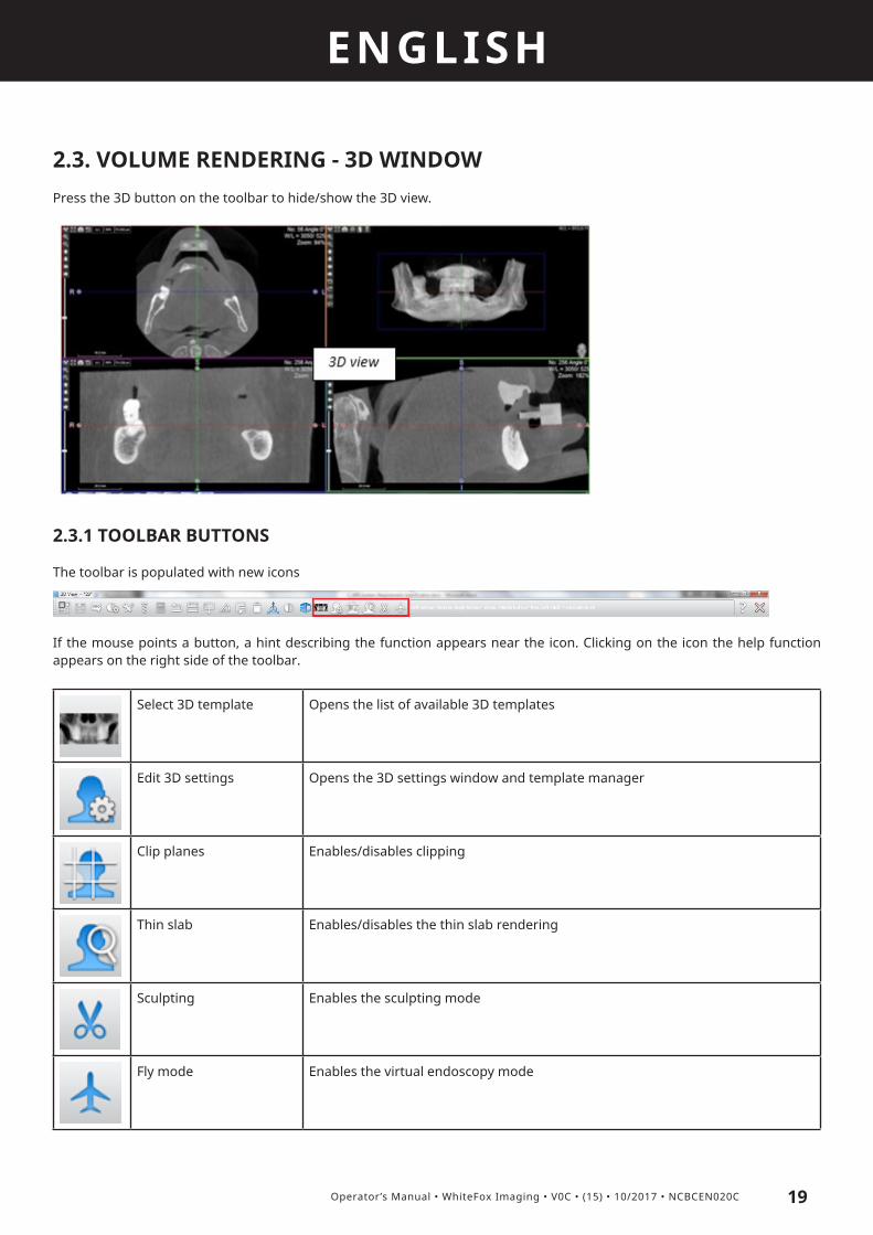
2.3. VOLUME RENDERING - 3D WINDOWPress the 3D button on the toolbar to hide/show the 3D view.
2.3.1 TOOLBAR BUTTONS
The toolbar is populated with new icons
If the mouse points a button, a hint describing the function appears near the icon. Clicking on the icon the help function appears on the right side of the toolbar.
Select 3D template Opens the list of available 3D templates
Edit 3D settings Opens the 3D settings window and template manager
Clip planes Enables/disables clipping
Thin slab Enables/disables the thin slab rendering
Sculpting Enables the sculpting mode
Fly mode Enables the virtual endoscopy mode
ENGLISH
20 Operator’s Manual • WhiteFox Imaging • V0C • (15) • 10/2017 • NCBCEN020C
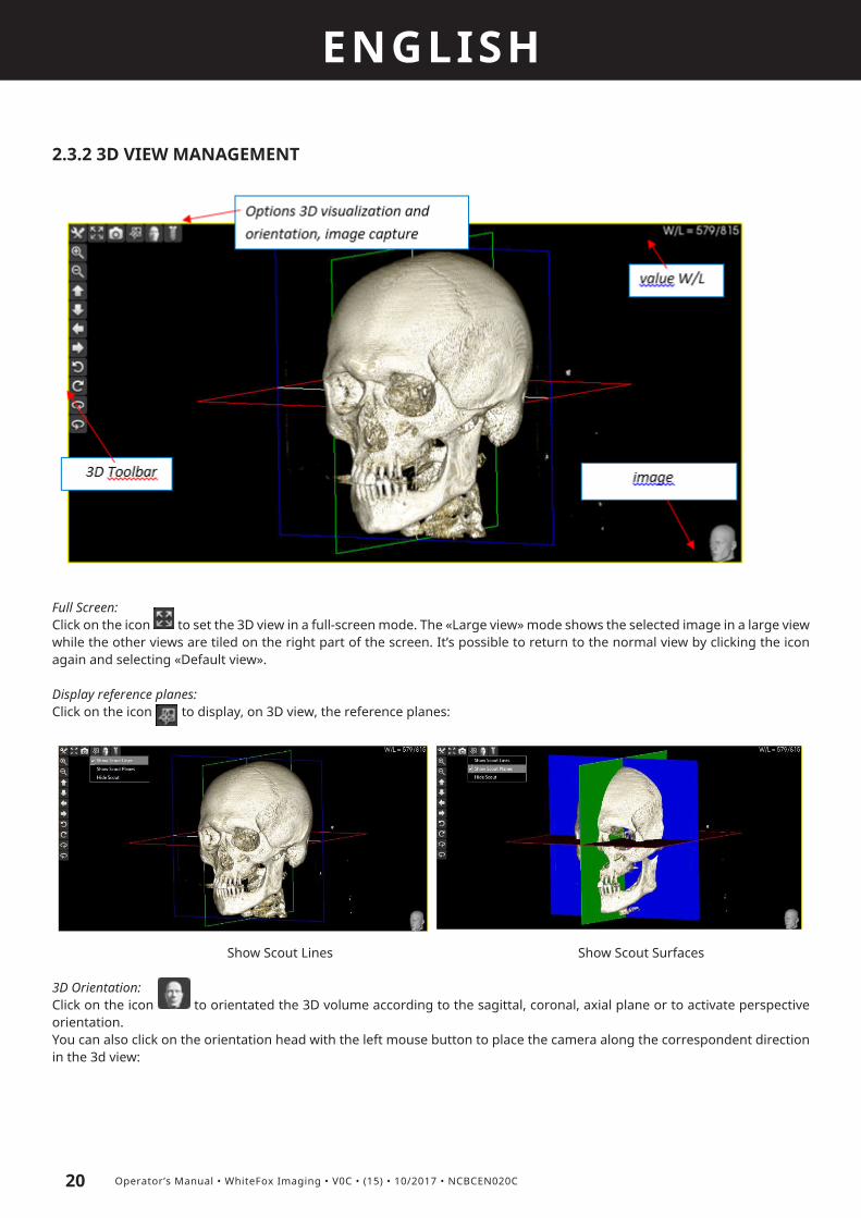
2.3.2 3D VIEW MANAGEMENT
Full Screen:Click on the icon to set the 3D view in a full-screen mode. The «Large view» mode shows the selected image in a large view while the other views are tiled on the right part of the screen. It’s possible to return to the normal view by clicking the icon again and selecting «Default view».
Display reference planes:Click on the icon to display, on 3D view, the reference planes:
Show Scout Lines Show Scout Surfaces
3D Orientation:Click on the icon to orientated the 3D volume according to the sagittal, coronal, axial plane or to activate perspective orientation.You can also click on the orientation head with the left mouse button to place the camera along the correspondent direction in the 3d view:
ENGLISH
21Operator’s Manual • WhiteFox Imaging • V0C • (15) • 10/2017 • NCBCEN020C
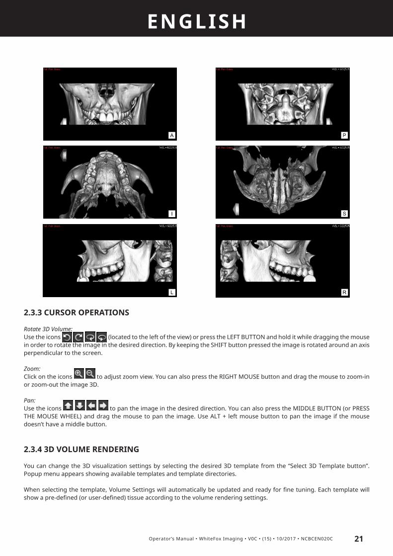
2.3.3 CURSOR OPERATIONS
Rotate 3D Volume:Use the icons (located to the left of the view) or press the LEFT BUTTON and hold it while dragging the mouse in order to rotate the image in the desired direction. By keeping the SHIFT button pressed the image is rotated around an axis perpendicular to the screen.
Zoom:Click on the icons to adjust zoom view. You can also press the RIGHT MOUSE button and drag the mouse to zoom-in or zoom-out the image 3D.
Pan:Use the icons to pan the image in the desired direction. You can also press the MIDDLE BUTTON (or PRESS THE MOUSE WHEEL) and drag the mouse to pan the image. Use ALT + left mouse button to pan the image if the mouse doesn’t have a middle button.
2.3.4 3D VOLUME RENDERING
You can change the 3D visualization settings by selecting the desired 3D template from the “Select 3D Template button”. Popup menu appears showing available templates and template directories.
When selecting the template, Volume Settings will automatically be updated and ready for fine tuning. Each template will show a pre-defined (or user-defined) tissue according to the volume rendering settings.

ENGLISH
22 Operator’s Manual • WhiteFox Imaging • V0C • (15) • 10/2017 • NCBCEN020C
Volume rendering is the process of generating an image directly from the volume data without the generation of an inter-mediate geometric model. Typically this is done by mapping the data values in the volume to the color and opacity of an imaginary semi-transparent material, and then rendering an image of this material.
People familiar with the medical imaging typically talk about the ‘window level’ and the ‘window width’ of an image. This is simply a way of describing the ‘brightness’ and ‘contrast’ of the image in order to show a specific tissue like colon or bone or both colon and bone in an image.
Volume rendering typically segments data on the basis of voxel attenuation. WhiteFox Imaging uses window width and level controls similar to those used for display of conventional axial CT images.
The window level and width can be adjusted to standard settings used to display different types of tissue: from soft tissue to bone, colon, or lung. In fact real-time window rendering permits the user to interactively alter the window setting and ins-tantly see the changes reflected in the displayed 3D image. This interactivity allows the user to rapidly customize the display to specific cases with varying levels of contrast enhancement and explore a variety of attenuation ranges by using the W/L button such as in the 2D views. However, in WhiteFox Imaging several window width and level settings are already predefi-ned, and are also a matter of customization.The width and level settings define a transfer function that maps the measured attenuation of each voxel to a corresponding color-scale value, which in turn is used to create the 3D image. The transfer function used in volume rendering also segments the data on the basis of voxel attenuation; it accurately models volume averaging of multiple materials within a voxel. A Whi-teFox Imaging user has complete control over the transfer function for making qualitative observations or for understanding complex 3D structures.
Opacity refers to the degree with which structures that appear close to the user obscure structures that seem farther away. Opacity can be set from 0% to 100% depending on the degree of how obscured the farther structures you wish to be. One sets high opacity values to produce an appearance similar to surface rendering, which helps to display complex 3D relationships clearly. Low opacity values allow the user to «see through» structures and can be very useful. In other words, data values of interest can be assigned high opacity values and a specific color to highlight their location within the volume while other data values can be assigned low opacity values to reduce their visual importance.

ENGLISH
23Operator’s Manual • WhiteFox Imaging • V0C • (15) • 10/2017 • NCBCEN020C
2.3.5 3D VOLUME SETTINGS
WhiteFox Imaging has several volume rendering functions to achieve the exact display desired by the user. Volume settings therefore enable the user to show four different tissues in an image by defining window level and width. For each tissue it’s possible to customize its display: select different color for each, and set opacity level to control the transparency.
In WhiteFox Imaging the window width and window level, opacity function, and color can be interactively changed via the Volume rendering settings. The window and level settings allow the user to look primarily at a range of data values. Window level stands for the midpoint of the range. The window is the width of the range. For example, if the level is 200, and the win-dow is 60, this lets the user look primarily at the 60 voxels in the range of 171 - 230. The tissue whose intensity value is lower than the minimum Intensity value (in our case 171) is displayed in black. By selecting the window width, one sets the range of Intensity values, which are displayed in a palette of greys (2D images) or any other two colors (3D images). Along with the window width, the maximum intensity value is also set (in our case 230). The tissue with the intensity value above the maxi-mum is displayed in white. It’s possible to modify any color to customize the view as much as possible.
Volume rendering is implemented with ray-casting method. The user have to define a “tissue” in order to control appea-rance of a 3D volume. This comes handy when the user wants to assign a different appearance to each object or tissue on the volume rendered image (for example lungs, skin...). With this object oriented approach also called Multi-tissue Control, the appearance of the volume rendered image is easily controllable.
If the user wants to control the appearance of the tissue, two mappings or transfer functions must be defined. The first transfer function, known as the scalar opacity transfer function, maps the scalar values into an opacity (transparency) or an opacity per unit length value. The second transfer function, referred to simply as the color transfer function, maps the scalar values into a color. The default settings can be set using the pre-defined volume templates, but the volume rendering func-tions can also be controlled manually.
Both interactive (when the 3D image is manipulated) and high quality (when the mouse button is released) rendering speeds can be adjusted by the user. To increase the 3D rendering quality by increasing the 3D rendering time, use the sliders in the 3D settings window under the TOOLS / Settings window.
Changes to the window and level settings affect all images on the Viewer window. The user can change the window and level settings by any of the following methods:

ENGLISH
24 Operator’s Manual • WhiteFox Imaging • V0C • (15) • 10/2017 • NCBCEN020C
+ Simply using the W/L button (or CTRL+left mouse button) and interactively adjusting both values in the 3D/Interactive Win-dow.
+ Moving the points of the correspondent indicator in the 3D volume settings window.
+ Inserting the W/L values manually in the correspondent text fields in the 3D volume settings window.
Changing the Window and Level Settings by using the mouse (preferred option):Setting the window width and level by using the mouse is by far the fastest and the simplest possibility. This is an interactive procedure which enables the user to gradually find a combination of window and level for optimal visualization of a specific tissue in the image. Place the cursor on an image in the 3D/Interactive Window, press and hold CTRL+left mouse button and:
1. scroll to the right to increase the window width2. scroll to the left to decrease the window width 3. scroll down to increase the window level4. scroll up to decrease the window level
Setting the window and level affects only the 3D object in the 3D/Interactive window. Example:
Template is set to Skin
Template is set to Skin, but has reset the window level in a higher Intensity value. This changes to less skin and more soft tissue.
Window level has been reset to an even higher value. This changes to less soft tissue and more bone.
Window level has been again reset to an even higher va-lue. This changes to show only bone.
Changing the Window and Level Settings by using the 3D volume settings window:The same result can be reached by manually sliding the borders of the tranfer functions under the image histogram. Chan-ging window level and width will result in the synchrone change in object display in the 3D/Interactive window. This way the user can interactively set the proper window level and width values to achieve the best tissue display.In the Volume settings menu it’s possible to set four different window level and width pairs. To enable or disable a new tissue settings the ‘ Tissue Enable/Disable’ button must be pressed.
Setting Opacity function:Opacity refers to the degree with which structures that appear close to the user obscure structures that seem farther away. Opacity can be set from 0% to 100% depending on the degree of how obscured the farther structures need to be. High opacity values produce an appearance similar to surface rendering, which helps to display complex 3D relationships clearly. Low opa-city values allow to «see through» structures and can be very useful. In other words, data values of interest can be assigned high opacity values and a specific color to highlight their location within the volume while other data values can be assigned low opacity values to reduce their visual importance.
The opacity function can be predefined and selected by pressing the right mouse button over the histogram window and moving the dots position until you find the right tissue on screen. Changing the position along the X axis will affect the tissue density, while moving the position along the Z axis will affect the tissue transparency.

ENGLISH
25Operator’s Manual • WhiteFox Imaging • V0C • (15) • 10/2017 • NCBCEN020C
Setting the color:WhiteFox Imaging uses a variety of color schemes for displaying images, including grayscale and different color combina-tions. Technically, this is done by assigning the same color to all of the voxels of a specific value but different colors to voxels of different values. Color setting is done manually by clicking with the right mouse button on the transfer function dots in the 3D settings window. Since different types of tissue tend to have different voxel values, different types of tissue can be set to appear in different colors. Thus the color identifies a specific type of tissue.
Shading options include 2 possibilities: choosing one of the preset shading options, and manual shading customization. In each case the 3D Settings button has to be selected. To choose from the preset shading options, go to the drop down menu, and select the desired option.
To customize shading manually, click on the shading button. A shading parameters menu will pop up, where the user can change the Ambient parameter, and/or Diffuse parameter, and/or Specular parameter, and/or Specular Power parameter. The number to the left is how much of the parameter component adds to the final shading effect. The normal range for each parameter weight is from 0.0 to 1.0. The parameter value can range from 0,0 on the left to 1,0 on the right.

ENGLISH
26 Operator’s Manual • WhiteFox Imaging • V0C • (15) • 10/2017 • NCBCEN020C
2.3.6 3D MIP (MAXIMUM INTENSITY PROJECTION)
Maximum intensity projection (MIP) is a volume rendering method, which projects the highest intensity voxel on each ray onto the corresponding pixel on the screen. The maximum intensity technique computes the maximum scalar value of all the voxels that contribute to the pixel, and displays this maximum value mapped through the scalar color and opacity transfer function.
Although this is a very simple projection mechanism, it is often favored by scientists who wish to see only in their opinion «real» values from within the dataset, as opposed to values derived after applying a compositing and shading step. The advantage of MIP is that the gray scale reflects CT attenuation rather than simulating light reflection as in SSD. Therefore, objects of differing attenuation could be differentiated. However, MIP still has the following problems:• One limitation of this projection method is that it is impossible to gain depth cues in a still image, and therefore a structure may be difficult to discern. MIP does not convey depth relationships, nor does it depict overlapping vessels as a focal increase in opacity. • Partial volume effects tends to result in vessel discontinuity at the area of high grade stenosis, rather than showing extreme narrowing as seen with conventional arteriography.• Partial volume or beam hardening may cause gradual attenuation transitions instead of a steep attenuation transition between adjacent structures, and MIP may include other structures one wants to suppress. • Mural calcium can also interfere with the grading of stenosis by means of MIP CT angiography. Contrary to the overestima-tion of luminal patency with SSD, stenosis can be overestimated with MIP if an eccentrically located calcification overlies the luminal contrast material.
It’s important to underline that shading has no effect on MIP.The MIP rendering method is accessible in the 3D settings window and it is one of the most used methods to inspect the vessels according to the medical literature, especially combined with the thin slab view.

ENGLISH
27Operator’s Manual • WhiteFox Imaging • V0C • (15) • 10/2017 • NCBCEN020C
2.3.7 THIN SLAB RENDERING (TSR) – 3D SLICE (OBLIQUE TRIM)
In order to visualize only a small part of the data between two “planes” – cut-planes – the Thin slab rendering method should be used. Thin-slab visualization is a method in which visualization of only a part of the volume is performed by rendering the data within a ‘slab’ (kind of a thick plane). This method shows small details much better than the standard volume rendering. This is a very useful rendering method because the cut-planes enable an inspection of the vessels without the influence of the bones.
Thin slab tool can be used as a virtual endoscope to point the attention on a particular anatomic structure without the inter-ference of the surrounding tissues.The tool is accessible through the “Thin slab” button on the main toolbar:
• Click on the “Thin slab button”• Click with the left mouse button on the structure of interest on any of the 2D views• Click with the LMB at the end of the region to visualize, the cursor becomes an arrow pointing toward the point of interest and the area outside the thin slab becomes dark.
• The thin slab thickness is decided by the user and it is the distance between the starting and ending points traced by the user

ENGLISH
28 Operator’s Manual • WhiteFox Imaging • V0C • (15) • 10/2017 • NCBCEN020C
The camera can be rotated on:a 2D views: rigid rotation of the camera around an axis perpendicular to the 2D view by clicking on the camera eye with the left mouse button and rotating ita 3D view: interactive rotation of the camera through the common “Cursor/rotate” icon on the toolbar by pressing the left mouse button, the thin slab cursor on 2D views will be updated accordingly and indicate the position and orientation of the camera
The thin slab thickness can be modified by selecting the planes and dragging them inward or outward the camera center, the field of view will be updated accordingly.The center of the thin slab rendering view can be moved simply by clicking2.3. on another point on 2D views or by dragging the mouse with the left mouse button pressed in the desired direction.
2.3.8 CLIPPING PLANES
The easiest way to remove the unwanted data is to change the boundaries of the data, in other words change the so called VOI (volume of interest). To change the boundaries of the data, just click on the “Clip planes” button on the toolbar and drag the colored boundary lines now visible on the MPR windows to the desired location. The image below shows an effect of the modified boundaries.

ENGLISH
29Operator’s Manual • WhiteFox Imaging • V0C • (15) • 10/2017 • NCBCEN020C
This method is very useful for removing the structures other that the patient’s body (acquisition table for example, or metallic artifacts).By pressing the button again the volume is set back to its original size.To permanently remove the unwanted data click on the “Trim image” label under the “Tools” icon, the software will show a wizard to perform the definitive trimming operation. The result of the processing can be stored in a project.
The “undo” command has no effect on this function and it removes any 3D object placed in the volume.

ENGLISH
30 Operator’s Manual • WhiteFox Imaging • V0C • (15) • 10/2017 • NCBCEN020C
2.3.9 SCULPTING
Click on the “Sculpting” button on the toolbar to cut a region from the 3D visualization. Click with the left mouse button point by point around the region to cut, then press the «Sculpt region» button to confirm the cut. It is possible to adjust the points position by dragging them with the LMB, before pressing the cutting button, or invert the region to cut by selecting the cor-respondent button.The region inside the sculpting polygon is deleted in the 2D images too. Click on the “Undo” button on the toolbar to restore the region back. By gradually sculpting the volume it is possible to obtain the desired visualization.Free-form selection is supported by keeping the SHIFT button pressed while dragging the mouse around the region to select.
Pay attention, all the regions that lie along the selected area normal will be deleted as well.
2.3.10 FLY MODE
Fly mode simulates the use of an endoscopic camera inside the 3D model of the patient. Click on the correspondent icon to enter the fly mode:
ENGLISH
31Operator’s Manual • WhiteFox Imaging • V0C • (15) • 10/2017 • NCBCEN020C
Click with the LMB on the starting point/camera position (eye cursor), then again on the target point/camera direction (cross-hair cursor).The camera is oriented along the current cursor view, to change its orientation use the Fly toolbar on the left side of the 3D view.Clicking on the Fly view with the left mouse button will enable the user to move a step forward, clicking with the right mouse button will move a step backword, clicking both the mouse buttons will rotate the camera without moving.The interactive 3D image quality can be set in the 3D settings window under TOOLS / Settings menu. Click on the Fly icon again to exit the Fly mode.
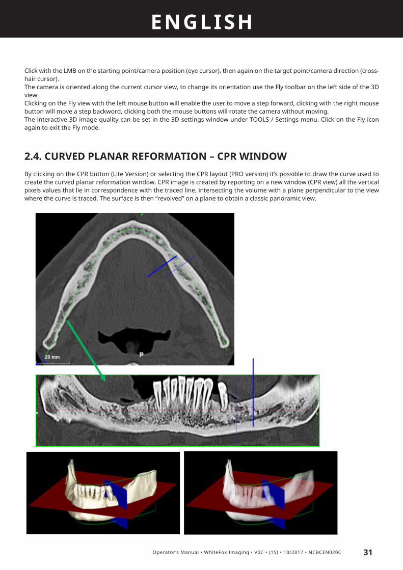
2.4. CURVED PLANAR REFORMATION – CPR WINDOWBy clicking on the CPR button (Lite Version) or selecting the CPR layout (PRO version) it’s possible to draw the curve used to create the curved planar reformation window. CPR image is created by reporting on a new window (CPR view) all the vertical pixels values that lie in correspondence with the traced line, intersecting the volume with a plane perpendicular to the view where the curve is traced. The surface is then “revolved” on a plane to obtain a classic panoramic view.

ENGLISH
32 Operator’s Manual • WhiteFox Imaging • V0C • (15) • 10/2017 • NCBCEN020C
2.4.1 CURVE CREATION
Click on the “Layout” button in the toolbar and select the «CPR» icon to start the CPR drawing mode and choose the subject of the curve:
Dental CPR WizardClicking on this option will start a «wizard» that guides the user in every step of the procedure (see the correspondent chapter for reference):

ENGLISH
33Operator’s Manual • WhiteFox Imaging • V0C • (15) • 10/2017 • NCBCEN020C
Custom CPRChoose the axial section where you want to draw the Dentascan curve.
• Use the LEFT MOUSE BUTTON to add points to the curve (start from the bottom left part of the axial image and draw an arch path by following the middle line between the cortical bone walls)• Use RIGHT MOUSE BUTTON on a point and select the correspondent command on the pop up menu to delete it• Click on a point with LEFT MOUSE BUTTON and drag it to move the point
• Click on the buttons on the CPR view to set the CPR height parameter• Click FINISH CURVE to stop the drawing mode • Click on the CPR image toolbar and on EDIT to bring back the drawing mode and edit the curve.
2.4.2 CURSOR OPERATIONS
Click on the CPR image to navigate along the CPR curve. The cursor and viewing direction of the MPR windows will update accordingly.Dragging the arrows at the end of the cursor will rotate the views of 360°, centered in the point set on the CPR view; clicking again on the CPR view will reset the cursor to be tangent to the CPR curve. All the MPR and navigation (zoom, pan,…) functions and are still available in CPR mode.
To offset the CPR curve inward and outward click on the icons or rotate the mouse wheel while pointing the CPR view.

ENGLISH
34 Operator’s Manual • WhiteFox Imaging • V0C • (15) • 10/2017 • NCBCEN020C
2.4.3 2D VIEWS MANAGEMENT
Most of the 2D tools in the toolbar and mouse actions can be used on CPR image.
To exit CPR layout click on the layout icon on the toolbar and select MPR.
CPR options View:To open the CPR options menu click on the icon positioned in the upper left corner of the Dentascan:
• Add to report: selects the images for the advanced radiology report tool• Reset MPR Angles: allows to undo any inclination of the reference axis.• Zoom 100%: sets the scale of the view to 1:1 dimensions• Zoom Best Fit: sets the scale of the view to fit the screen• Edit CPR Curve: restores back the drawing points to edit their position.• Reset CPR Offset: restore the original position of the CPR curve.• Delete CPR curve: deletes the current CPR curve.

ENGLISH
35Operator’s Manual • WhiteFox Imaging • V0C • (15) • 10/2017 • NCBCEN020C
Display Mode / CPR Filters:Click on the MPR icon on CPR view to change the view mode of the CPR curve or to apply a preset filter:
2.4.4 AUTOMATIC CPR CREATION
As an alternative to manual CPR drawing, in wizard mode WhiteFox Imaging can propose an optimal CPR arch based a pre-set curve, different from maxilla to mandibleTo access the automatic CPR drawing click on the Mandible/Maxilla button, the arch will be positioned in the middle of the axial image:
The curve can be moved using the central cursor and can be adjusted to follow the anatomy curvature by moving the dots along it. If the curve is not satisfying, click on the MANUAL mode to draw it from scratch. The newly created curve can be ad-ded as template by clicking on the MANUAL mode icon with the RMB and selecting «Save CPR as maxilla/mandible template».Click OK to confirm the curve shape.

ENGLISH
36 Operator’s Manual • WhiteFox Imaging • V0C • (15) • 10/2017 • NCBCEN020C
2.5. MEASUREMENTSSimple 2D graphic tools include those:
+ to measure the length between 2 points with a Distance tool,+ to measure an angle between 3 points with an Angle tool, + to make an analysis of a region with a Polygon tool using a variety of functions like maximum, minimum and mean value of density value inside the region or its standard deviation.
Use the Distance, Angle or ROI tool to measure any structure in a MPR image. Moreover it’s possible to extract a full profile of the tissue, making a pixel value analysis based on a pixel value table, pixel coordinates and investigation of the pixel’s value density.All the measurements tools are disabled in the CPR view.
2.5.1 MEASURE DISTANCE
Length between 2 points is measured by activating the “Measure distance” button on the toolbar. As soon as marking the 2 points, the distance is calculated. It’s also possible to change its angle or move it to another location.
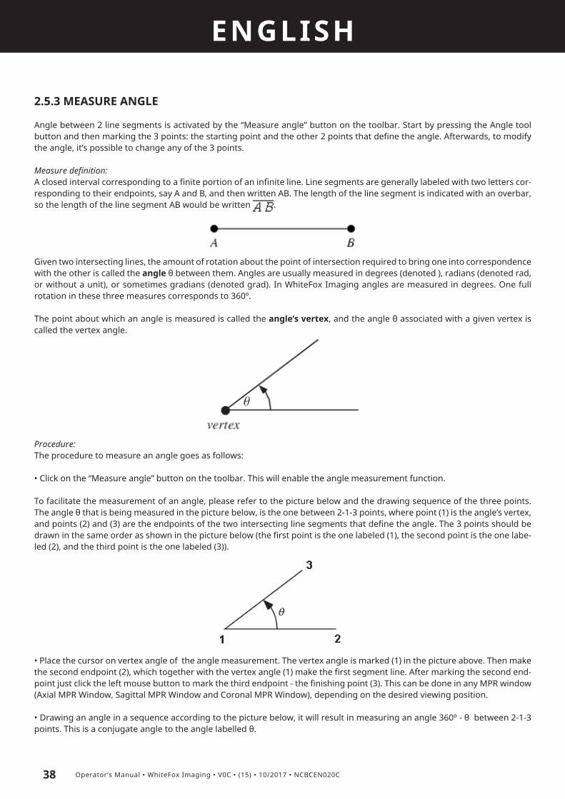
Measure definition:A closed interval corresponding to a finite portion of an infinite line. Line segments are generally labeled with two letters cor-responding to their endpoints, say A and B, and then written AB. The length of the line segment is indicated with an overbar, so the length of the line segment AB would be written .
Procedure:Measuring a distance is a simple procedure which enables the user to measure a distance between 2 selected endpoints (A, B) on a specific tissue or object in the image. It also allows corrections to change any of the 2 originally chosen points, which means carrying the line segment to another location in the image, or changing its angle and its size. The procedure goes as follows:
• Click on the “Measure distance” button on the toolbar. This will enable the distance measurement function.
• Place the cursor on the starting point (the first endpoint) of the distance measurement and press the left mouse button. This can be done in any MPR window (Axial MPR Window, Sagittal MPR Window and Coronal MPR Window), depending on the desired viewing position.
• Press the left mouse button when the second endpoint is reached – the finishing point of the measuring line segment.
To draw another line segment to measure the distance between two points, the user has to enable the Distance Tool again by pressing the “Measure distance” button on the toolbar.To delete all measurements, just press the “Delete Measurement” button on the toolbar. To delete the selected measurement right click on the measure value and choose YES when prompted.
Changing the segment line:To change any of the 2 originally chosen endpoints, the user can do the following.
• Change an angle: place the cursor on the endpoint of the line segment, press the left mouse button, hold it, and drag the mouse in the desired direction.
• Change size of the line segment: place the cursor on the endpoint of the line segment, press the left mouse button, hold it, and drag the mouse in a desired direction. Its size is displayed connected to the line segment and it reads in millimetres. The size display and the line segment are connected so that they don’t mix up when there is more than 1 line segment.
To change the line segment size display’s location, just place the cursor over it, click with the left mouse button, and hold it while dragging the display to another location.
ENGLISH
37Operator’s Manual • WhiteFox Imaging • V0C • (15) • 10/2017 • NCBCEN020C
2.5.2 HU GRAPHIC
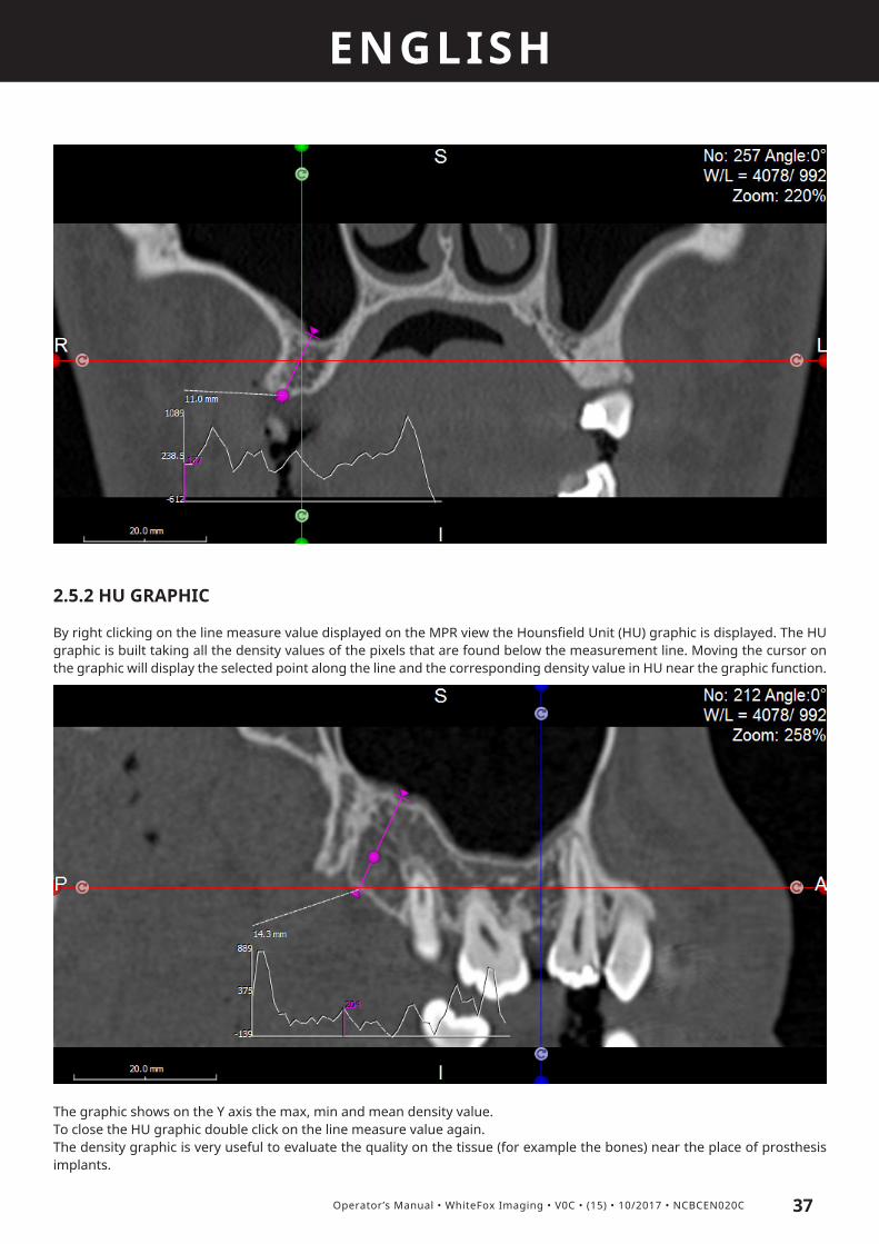
By right clicking on the line measure value displayed on the MPR view the Hounsfield Unit (HU) graphic is displayed. The HU graphic is built taking all the density values of the pixels that are found below the measurement line. Moving the cursor on the graphic will display the selected point along the line and the corresponding density value in HU near the graphic function.
The graphic shows on the Y axis the max, min and mean density value.To close the HU graphic double click on the line measure value again.The density graphic is very useful to evaluate the quality on the tissue (for example the bones) near the place of prosthesis implants.
ENGLISH
38 Operator’s Manual • WhiteFox Imaging • V0C • (15) • 10/2017 • NCBCEN020C
2.5.3 MEASURE ANGLE
Angle between 2 line segments is activated by the “Measure angle” button on the toolbar. Start by pressing the Angle tool button and then marking the 3 points: the starting point and the other 2 points that define the angle. Afterwards, to modify the angle, it’s possible to change any of the 3 points.
Measure definition:A closed interval corresponding to a finite portion of an infinite line. Line segments are generally labeled with two letters cor-responding to their endpoints, say A and B, and then written AB. The length of the line segment is indicated with an overbar, so the length of the line segment AB would be written .
Given two intersecting lines, the amount of rotation about the point of intersection required to bring one into correspondence with the other is called the angle θ between them. Angles are usually measured in degrees (denoted ), radians (denoted rad, or without a unit), or sometimes gradians (denoted grad). In WhiteFox Imaging angles are measured in degrees. One full rotation in these three measures corresponds to 360º.
The point about which an angle is measured is called the angle’s vertex, and the angle θ associated with a given vertex is called the vertex angle.
Procedure:The procedure to measure an angle goes as follows:
• Click on the “Measure angle” button on the toolbar. This will enable the angle measurement function.
To facilitate the measurement of an angle, please refer to the picture below and the drawing sequence of the three points. The angle θ that is being measured in the picture below, is the one between 2-1-3 points, where point (1) is the angle’s vertex, and points (2) and (3) are the endpoints of the two intersecting line segments that define the angle. The 3 points should be drawn in the same order as shown in the picture below (the first point is the one labeled (1), the second point is the one labe-led (2), and the third point is the one labeled (3)).
• Place the cursor on vertex angle of the angle measurement. The vertex angle is marked (1) in the picture above. Then make the second endpoint (2), which together with the vertex angle (1) make the first segment line. After marking the second end-point just click the left mouse button to mark the third endpoint - the finishing point (3). This can be done in any MPR window (Axial MPR Window, Sagittal MPR Window and Coronal MPR Window), depending on the desired viewing position.
• Drawing an angle in a sequence according to the picture below, it will result in measuring an angle 360º - θ between 2-1-3 points. This is a conjugate angle to the angle labelled θ.

ENGLISH
39Operator’s Manual • WhiteFox Imaging • V0C • (15) • 10/2017 • NCBCEN020C
After the third endpoint is marked, the Angle Tool deactivates itself by default. To measure another angle, the user should activate the “Measure angle” button on the toolbar.
To delete all measurements, just press the “Delete Measurement” button on the toolbar. To delete the selected measurement right click on the measure value and choose YES when prompted.
Changing the angle:To change any of the 3 originally chosen points (vertex angle (1), the second (2) and third endpoint (3)), do the following: place the cursor on any of the marking points and the cursor style should change to the ‘move’ cursor style. When in ‘move’ style, press the left mouse button, hold it, and drag the mouse in a desired direction. This will result in changing the selected mar-king point’s position, leaving the other two marking points intact.

ENGLISH
40 Operator’s Manual • WhiteFox Imaging • V0C • (15) • 10/2017 • NCBCEN020C
2.5.4 MEASURE POLYGON
Activating the “Measure polygon” button on the toolbar it’s possible to make an analysis of a selected region based on the area size, intensity mean value, maximum intensity, minimum intensity and standard deviation of the intensity mean value. Start by pressing the “Measure polygon” button on the toolbar and draw a polygon in a freehand mode or in a preset mode. Afterwards, to modify the polygon, it’s possible to move its text description to another location or change any of the marking points. WhiteFox Imaging enables to draw a polygon more or less in a freehand mode, therefore the polygons are principally non-regular polygons. This feature empowers the user to measure a non-regularly shaped region as accurately as it can be measured.
Measure definition:Polygon is a closed plane figure with n sides. Polygons are named according to the number of sides and angles they have. The most familiar polygons are the triangle, the rectangle, and the square. A regular polygon is one that has equal sides. Polygons also have diagonals, which are segments that join two vertices and are not sides. For example, the pentagon (see picture below) has 5 sides and 5 vertices (A, B, C, D, E).
Procedure:The procedures to measure a polygon in two possible modes go as follows. The first possibility is to a draw a polygon in a freehand mode, the second option is to draw a region by marking points, which will represent the polygon’s vertices (ending points at each edge).
• Freehand mode: just switch the Polygon tool on and draw a polygon by pressing the shift button at the same time as drawing the polygon. When finished drawing the polygon, just release the shift button. Click on FINISH POLYGON button to end the drawing phase. Moving the text describing the polygon: place the cursor over the text, click on it with the left mouse button and drag it in a new desired location in the image.
• Marking points: just switch on the Polygon tool and draw a polygon by marking a few points to define the polygon’s vertices. Click on FINISH POLYGON button to end the drawing phase. This will result in deactivating the Polygon function. Moving the text describing the polygon: place the cursor over the text, click on it with the left mouse button and drag it in a new desired location in the image.

ENGLISH
41Operator’s Manual • WhiteFox Imaging • V0C • (15) • 10/2017 • NCBCEN020C
To delete all measurements, just press the “Delete Measurement” button on the toolbar. To delete the selected measurement right click on the measure value and choose YES when prompted.
Changing the polygon:Place the cursor on any of the vertices and the cursor style should change to the ‘hand’ cursor style; make a left mouse click on it and drag the cursor in a desired direction. The polygon will stretch outwards or inwards only in the selected vertex.
2.5.5 ANNOTATE
By clicking on the “Annotate” button on the toolbar the user can add his comments to the images.
Procedure:• Click on the “Annotate” button on the toolbar. This will enable the annotation function.• Click with the left mouse button on the desired view to define the first point of the arrow.• Drag the arrow and click with the left mouse button when it points the region of interest; the “Edit annotation” window, where the user can insert the desired comment, will pop up.
The Annotations window gives the user the possibility to store the most used comments in a local database for future use.To delete all the annotations, just press the “Delete Measurement” button on the toolbar. To delete the selected annotation right click on the measure value and choose YES when prompted.
Changing the annotation:Place the cursor on any of the vertices and the cursor style should change to the ‘hand’ cursor style; make a left mouse click on it and drag the cursor in a desired direction, the annotation text or the arrow tip will move accordingly.
Changing the font and line color:Click on the “Tools” icon on the toolbar, select “Settings” and select the “Fonts” options under General tab to modify them.
2.5.6 2D MEASUREMENTS IN 3D VIEW
All the measurement functions can be enabled in the 3D view too, with the following differences:
• Measure distance: it is a distance measured on the view plane projection, not a real 3D distance. • HU graphic: is not enabled in 3D view• Measure angle: it is an angle measured on the view plane projection• Measure polygon: it is an area measured on the view plane projection, not a real 3D surface area. • Annotate: it’s possible to insert an annotation.
While performing the measurements in 3D view the rotation and contrast settings of the volume are disabled.

ENGLISH
42 Operator’s Manual • WhiteFox Imaging • V0C • (15) • 10/2017 • NCBCEN020C
To delete the selected measurement right click on the measure value and choose YES when prompted. To delete all the annotations and measurements, just press the “Delete Measurement” button on the toolbar. The volume operations are then restored.
2.5.7 CALCULATE VOLUME
It is possible to calculate the volume of the objects visible on 3D view. To access the command click on the TOOLS icon and click on “Volume Measurement”. A dialog box will appear on the top of 3D view with the volume value in cubic centimeters:
The voxels used for calculation will be displayed in red on the MPR views.
Click on the «X» button to remove the volume measurement.

ENGLISH
43Operator’s Manual • WhiteFox Imaging • V0C • (15) • 10/2017 • NCBCEN020C
2.6. IMAGE CAPTURETo save the image corresponding to a single view, in .bmp format, please click the icon on the toolbar at the top left corner of each view, a browse window pops out to choose the desired location to save the file.To save the entire screen use the icon «Tools» on the toolbar and click «Save Desktop».
2.7. IMPLANTS AND 3D OBJECTS INSERTIONWhiteFox Imaging can import implants and 3D objects to perform surgery simulation and exchange data with any CAD-CAM system working with STL files open architecture.Typically the user will insert dental implants to simulate the complete treatment plan, the following tools are focused on this procedure. In order to guide the user in the planning process, a «wizard» tool has been implemented and will be explained in chapter 2.9.9.
Manage implants:To add an implant click on the “Implants/Nerves” icon on the toolbar, the following options menu appears (image referred to Implant layout view):
• Place the cursor on the panoramic view in the desired implant position• Insert the implant by clicking on the «Add Implant» button, a teeth map will appear

ENGLISH
44 Operator’s Manual • WhiteFox Imaging • V0C • (15) • 10/2017 • NCBCEN020C
• Select the number of the tooth correspondent to the implant position, then click on OK. If the «Use Implant library» check-box is selected the STL library with the implants drawings coming from the Companies pops out (see paragraph below).• Click with the LEFT MOUSE BUTTON on the point corresponding to the implant top (while moving the mouse the software shows the distance between the two insertion points) on the cross sections view, then on the point corresponding to the implant bottom.
The implant model is added both in MPR views (the implant sections are calculated dynamically while moving the cursor) and 3D view, and it appears as a new line in the implant grid:
To add multiple implants move the cursor in the new position, then proceed as before.
To select an implant move the mouse over it, when its color changes or the mouse pointer changes shape, click on it with the left mouse button to select it. As an alternative click on the desired implant in the grid. After planning the implants position, clicking on implants lines, you can move easily from one to the other. All the views will be recalculated dynamically centered on the selected implant. To delete an implant just select it and click on the “Delete” button.
To change the implant’s parameters just select it and insert the new parameters in the correspondent fields. To change the

ENGLISH
45Operator’s Manual • WhiteFox Imaging • V0C • (15) • 10/2017 • NCBCEN020C
implant conicity RIGHT CLICK on the implant center, select «Conic diameter» and choose between the options: «Set for this implant» or «Set for all implants», then choose the implant bottom diameter.
To lock an implant in the desired position click on the “Lock implants” icon. The implant will be selectable only from the drop-down list of implants, but won’t be movable.
Implants movement:Horizontal/Vertical movement (according to the image): select an implant, approach the «hotspot» placed on the implant center and use the arrows icons that appear to move the icons in the correspondent direction (the implant will be moved 0,5mm per click, as set in the Settings menu under the TOOLS icon):
Use the keys W - S - A - D on the keyboard as shortcuts to move the implant up - down - right - left.Click on the central implant hotspot with the LMB and drag the mouse to freely move the implant in the selected plane.
Translation along the implant axis, select an implant and use the arrow keys on the keyboard (the implant will be moved 0,5mm per click as set in the Settings menu under the TOOLS icon).
Rotation of the implant: select an implant, click on the rotation points on the top/bottom of the implant axis, press the LMB and drag it in the desired direction to rotate the implant in respect of the implant bottom/top:

ENGLISH
46 Operator’s Manual • WhiteFox Imaging • V0C • (15) • 10/2017 • NCBCEN020C
Use the keys Q - E to rotate the implant centered on top by 1° counterclockwise/clockwise, use the keys Z - C to rotate the implant centered on bottom by 1° clockwise/counterclockwise
Move the implant in 3D view: it is possible to move the implants also in the 3D view by clicking on the implants icon on the 3D
toolbar to «activate» them. After the icon is selected click on the desired implant, the rotation dots appear on the implant axis extremities and its possible to move the implant by clicking and dragging it with the LMB pressed, or rotate it by clicking on the yellow dots with the LMB and dragging the mouse in the desired direction. The implant is moved/rotated on a plane normal to the 3D view camera. If the mouse is pointed outside the implant, it’s possible to rotate the volume and so modify the implant rotation/movement direction. The implant profiles on the MPR views are updated accordingly as soon as the mouse button is released.
To «deactivate» the implant movement in 3D view click again on the implant icon on the 3D toolbar
Manage 3D files through the Library:If the user wants to add an implant file from the Library, the “Use Implant Library” checkbox should be selected on the teeth map before clicking on OK. The Implant Library is loaded as follows:
The library shows the manufacturers list, for every manufacturer a list of implants models is available, as well as a list of abut-ments, when available. On the right side of the window a preview is visible.It is possible to click on «Import DB» button to add new libraries (prepared by de Götzen S.r.l. - ACTEON Group) or click on

ENGLISH
47Operator’s Manual • WhiteFox Imaging • V0C • (15) • 10/2017 • NCBCEN020C
the «Export DB» button to create a backup of the database in the desired location. The library files are encrypted for security reasons and cannot be exported/modified by the user.To remove the selected abutment from the implant preview, just click on the «Clear Abutment» button.
The imported file is added both in MPR views (the STL sections are calculated dynamically while moving the cursor) and 3D view:
To change the implant model that was inserted from the library, click with the RMB on the hotspot in the middle of the im-plant and select «Edit implant...»; the implant library is opened again and it’s possible to choose another implant model, the software will keep the same insertion point and direction of the previous one.
Calculate the bone density around the implant:The aim is to show, both through color maps and numerically, the grey values correspondent to different bone densities in a region defined by the user around the selected implant. To show the bone density around the selected implant click on the «Bone density» icon on the implant grid
To set the thickness of the area surrounding the implant that will be included for the calculation (mm), click with the RMB on the implant central hotspot and select «Bone density...», then define the minimum density value (in HU) that will be displayed in red in the colour map and the maximum density value that will be displayed in green, as well as the area thickness.

ENGLISH
48 Operator’s Manual • WhiteFox Imaging • V0C • (15) • 10/2017 • NCBCEN020C
The axial view is centered perpendicular to the implant axis and zooming in the HU values appear inside every voxel around the implant inside the previously set thickness. The concept drawing of the model is reported here:
The calculated values can be exported in MS Excel by clicking on the “Export to XLS” button.
Snap the cursor to the implant axis:When working on tilted implants it’s possible to automatically align the cross section to the implant axis, in order to see the
implant sections along the axis itself. In order to do this click on the «Snap» icon
Insert the abutments:After the implant is in position it’s possible to add the abutment by clicking on the «Abutments» tab and adding the specific abutments parameters (height, angle and rotation):

ENGLISH
49Operator’s Manual • WhiteFox Imaging • V0C • (15) • 10/2017 • NCBCEN020C
The abutment can be loaded also from the Implant Library, if the implant is loaded from the Library itself.
Insert 3D objects:Clicking on the «Model» and «Prosthesis» button enables the user to import STL files coming from optical scanners and insert them in the Patient reference system.After the models have been inserted, clicking on the buttons will show/hide the correspondent object in 3D and MPR views:

ENGLISH
50 Operator’s Manual • WhiteFox Imaging • V0C • (15) • 10/2017 • NCBCEN020C
Add fixation pins:It is possible to insert the dental guide fixation pins by clicking on the «Pins» tab, selecting the cross section where adding the pin and then clicking on the «Add pin» button. The fixation pin is added in the same way a standard implant is inserted, with a different direction.
Show a preview of the dental guide sleeves:By clicking on the correspondent button a preview of the selected guide sleeve model (selectable in the Implant options un-der the settings menu) is shown on the top of the implants. If the sleeve color turns to blue, then an intersection with another sleeve or STL model is found and it’s necessary to move the implant accordingly:
Export implants / 3D objects:Implants and 3D objects can be exported in STL file format by clicking on the SAVE icon and selecting the desired option: «Export to STL file» (all the objects are exported in the same STL file) or «Export each object to its STL file». The STL files are exported in the Patient Reference System.Not all the WhiteFox Imaging versions support the STL file export function.

ENGLISH
51Operator’s Manual • WhiteFox Imaging • V0C • (15) • 10/2017 • NCBCEN020C
2.8. NERVE DRAWINGTo draw the mandibular nerve canal click on the «Nerve» tab and on the “Add Nerve” button on the implants grid, then start clicking point by point along the mandibular canal trajectory on the MPR views or on the CPR view:
o Use LMB to add points to the curve o Use RMB on a point to delete it o Click on a point with LMB and drag it to move the point o Click FINISH to stop the drawing mode o Click on EDIT icon to bring back the drawing mode and edit the curveThe nerve/curve is visible also in 3D.The following parameters can be set for the nerve:
2.9. ADVANCED OPERATIONSWhiteFox Imaging can perform very specific and advanced tasks on DICOM images. Under the “Tools” icon in the toolbar there are many specialized functions useful both for diagnostic and research tasks.

ENGLISH
52 Operator’s Manual • WhiteFox Imaging • V0C • (15) • 10/2017 • NCBCEN020C
2.9.1 SAVE PROJECT
It is possible to save a “Project” in WhiteFox Imaging, meaning that the user can store the following information:• CPR curves• Trimming and sculpting operations• Implants and 3D objects position (nerves, STL files)
To save a project click on the “Save project” icon with the LMB, choose the project name and click OK to store the information. WhiteFox Imaging supports multiple project save, the projects with the same file name will be overwritten. WhiteFox Imaging projects are automatically stored in the patient’s folder.
To load a project double click on the project name in the Projects list in the Patient Database window.
To delete a project click on the «X» icon that appears on the same line of the project to delete, a popup window will appear to ask for a confirmation, the project is deleted permanently.
To export a project as a .zip file click on the “Zip/Upload project” icon that appears on the same line of the project to export. There are two options: the first (“Open series in explorer”) opens the folder where the selected series is stored, the second (“ZIP/Upload series”) allows the user to export and compress the selected series and projects for backup purposes or to manufacture a surgical guide. After the compression the software asks the user if the data should be sent to de Götzen® S.r.l. (Acteon Group) for further processing, if the user clicks on YES the default internet browser is opened and directed to the https://whitefox.wetransfer.com files exchange website. If a project is present, then a Liability Form must be compiled and accepted by the user in order to send the project to the manufacturing Company.
Deleted project files are not moved to the Windows recycle bin but are permanently erased!
2.9.2 TRIM IMAGE
The trimming operation is suggested to reduce the volume of interest in case of huge stacks, thus reducing the computatio-nal effort and speeding up the volume processing.It is recommended to perform this operation as a FIRST STEP, before any other operation.
Procedure:• Click on 3D button to load the volume• Click on “Trim mode” and drag the coloured lines to reduce the volume (the trimmed part preview becomes shaded)• Click on OK to confirm

ENGLISH
53Operator’s Manual • WhiteFox Imaging • V0C • (15) • 10/2017 • NCBCEN020C
It is not possible to retrieve the original volume from a trimmed project. To load the original volume the stack should be ope-ned again from the Patient List and saved under a new project name.
2.9.3 FLIP IMAGE
Click on the “Flip image” label under the “Tools” icon to change the orientation of the X – Y – Z axis.
2.9.4 IMAGE FILTERING
Click on the “Filter Image” option under the “Tools” button on the toolbar to perform 2D image filtering operations. Image filtering is useful when the image information is covered with “noise” coming from low dose radiation machines or to process images previously filtered by the radiologist.The filtering window appears as follows:
Procedure:• Choose the filter from the drop down list• Move the bar to select the filter power and see the preview below• Click on APPLY to process all the images with the selected filter
The available filters are the following: a Median filter: used to reduce the noise of the image when it appears grainy. The difference from the previous filter is that according to the scientific literature this filter preserves the images features better (image borders) than a standard Gaussian filter. The resulting images will present nice borders and a good noise reduction in uniform regions

ENGLISH
54 Operator’s Manual • WhiteFox Imaging • V0C • (15) • 10/2017 • NCBCEN020C
a Sharpen filter: used to enhance the image borders when the image has already been processed with a smoothing filter and the features are too much “foggy”
To cancel the filtering operation click on the “Undo” button on the toolbar. It is possible to “undo” just one filtering operation.
2.9.5 BONE/TISSUE REMOVAL
It is often useful to remove parts of the patient’s anatomy to better perform a diagnosis or simulate a treatment plan. For example:
- Remove the mandible/maxilla to perform a dental implant simulation on the remaining part- Extract a tooth to evaluate a post-estractive site- Delete a radiologic guide from the patient mouth- Separate blood vessels with contrast medium from the bones- Remove high density implants (dental, orthopaedic,...) to study the bone around them- Delete regions not connected (vertebrae, ...)
The “Bone/Tissue removal” option under the “Tools” icon on the toolbar can perform these tasks and many more.
For example we would like to isolate the mandible from the following stack:
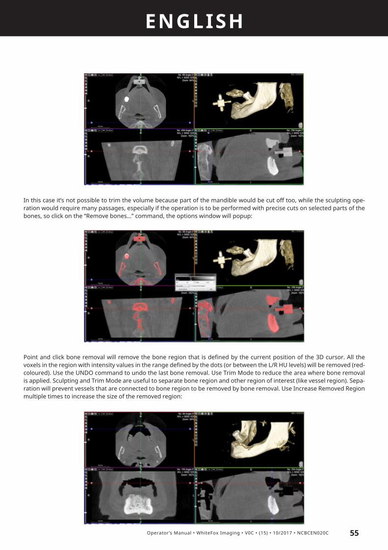
ENGLISH
55Operator’s Manual • WhiteFox Imaging • V0C • (15) • 10/2017 • NCBCEN020C
In this case it’s not possible to trim the volume because part of the mandible would be cut off too, while the sculpting ope-ration would require many passages, especially if the operation is to be performed with precise cuts on selected parts of the bones, so click on the “Remove bones...” command, the options window will popup:
Point and click bone removal will remove the bone region that is defined by the current position of the 3D cursor. All the voxels in the region with intensity values in the range defined by the dots (or between the L/R HU levels) will be removed (red-coloured). Use the UNDO command to undo the last bone removal. Use Trim Mode to reduce the area where bone removal is applied. Sculpting and Trim Mode are useful to separate bone region and other region of interest (like vessel region). Sepa-ration will prevent vessels that are connected to bone region to be removed by bone removal. Use Increase Removed Region multiple times to increase the size of the removed region:

ENGLISH
56 Operator’s Manual • WhiteFox Imaging • V0C • (15) • 10/2017 • NCBCEN020C
2.9.6 SURFACE GENERATION
WhiteFox Imaging can calculate and export a surface starting from the anatomical data. To calculate the surface click on the “Generate surface” command from the “Tools” icon on the toolbar:
Surface will be generated for the region that is defined by the Threshold Value. The region for surface generation contains all the voxels with intensity higher than the Threshold value. For faster execution and lower memory consumption adjust the Quality factor from the drop-down menu and reduce the level of detail of the generated surface.
To export the generated surface in STL file format click on e SAVE icon, select «Export to STL file» and choose the desired directory and filename.
2.9.7 WIZARD MODE
The wizard mode is a guided procedure that step by step prepares the Patient study for the virtual implant planning. The Wizard mode is accessible under the TOOLS menu or it’s possible to open the dataset directly in this mode by selecting the correspondent checkbox under the SETTINGS menu in the Patient Database window.
A video tutorial shows to the user the actions to perform for every step of the wizard.
Clicking on confirms the action and goes to the next step, clicking on cancels the action and exits the wizard.

ENGLISH
57Operator’s Manual • WhiteFox Imaging • V0C • (15) • 10/2017 • NCBCEN020C
The wizard follows the steps:
1. Image trimming: reduce the volume of interest
2. 3D setting: fine tune the 3D view to the desired template
3. CPR plane setting: select the axial image where tracing the CPR curve and, if necessary, modify the plane inclination accor-ding to the acquisition plane and patient anatomy. To modify the plane inclination click on the rotation pointer at the end of the green line on the scout view with the LMB, keep it pressed and drag the mouse in the desired direction.
4. CPR curve drawing: select the Mandible/Maxilla option, the software shows a pre-defined curve that can be adjusted by the user by moving the curve (through the central hotspot) or the dots. If the curve is not correct enough it is possible to switch

ENGLISH
58 Operator’s Manual • WhiteFox Imaging • V0C • (15) • 10/2017 • NCBCEN020C
to the «manual» mode and draw the curve from the beginning. Click on the recycle bin icon to reset the curve and on the «+» or «-» buttons to increase the curve height.
5. Nerve drawing: select the mandible part, the opposite one becomes shaded and it’s possible to draw the nerve on the CPR view by clicking the points with the LMB. The points can be also adjusted on the cross section view. Click on the recycle bin to reset the drawing.
6. Import 3D objects: select the STL files to import and assign the teeth number to the locations where the implants should be inserted. The teeth positions are remembered by the software that automatically moves the cursor in the correspondent position before inserting the implant. The tooth number is assigned
Clicking on OK will open the «Implant layout» to start the implant planning procedure.

ENGLISH
59Operator’s Manual • WhiteFox Imaging • V0C • (15) • 10/2017 • NCBCEN020C
2.10. SETTINGSThe Settings menu is retrievable from the TOOLS icon and includes the following tabs:General: set the font options, the general software layout and the crosshair type
3D Settings: set the software/hardware rendering options. By default the software reconstructs the 3D volume and MIP/Raysum images through software rendering (using CPU and RAM computational capabilities). If the computer that runs the software has an OpenGL based graphic card (nVidia), then it’s possible to activate the hardware rendering to increase the 3D volume quality and speed. While in software rendering mode move the sliders to fine tune the 3D view quality/speed (increa-sing the quality will reduce the reconstruction speed, depending on the installed hardware)

ENGLISH
60 Operator’s Manual • WhiteFox Imaging • V0C • (15) • 10/2017 • NCBCEN020C
Implant planning: set the implant tools options, including the type of guided surgery technique (in order to show the correct sleeves position) and the minimum distance between the implants and the nerve before showing a warning message to the user. The objects default colors can be modified as well.
Report settings: set the default Doctor name and logo for the implant report pdf file

ENGLISH
61Operator’s Manual • WhiteFox Imaging • V0C • (15) • 10/2017 • NCBCEN020C
2.11. WORKING WITH LAYOUTSWhiteFox Imaging 4.0 implements the “layouts” to help the surgeon in optimizing the image processing workflow. Each layout is focused on a particular operation or surgery and enables the user to perform specific analysis on the dataset.
The available layouts are reported here:
MPR/3D Default layout
CPR Layout focused on the CPR management
Implant Layout that reproduces the standard Dentascan view for dental implant simulation
Ortho/CEPH Layout focused on orthodontic and cephalmetric applications
TMJ Layout with multiple views to analyze temporomandibular joints
Airways Layout focused on airways study
2.11.1 MPR/3D LAYOUT
It is the default layout that opens when the user loads the dataset. All the common operations can be performed on this layout.

ENGLISH
62 Operator’s Manual • WhiteFox Imaging • V0C • (15) • 10/2017 • NCBCEN020C
2.11.2 CPR LAYOUT
This layout is recommended to correctly manage the CPR curve. Clicking on the icon will show the following options:- Dental CPR wizard- Custom CPRThe first opens the wizard sections that deals with the curve creation, the second enables the user to draw the curve directly on the axial image for a fast curve reconstruction
2.11.3 IMPLANT LAYOUT
This layout reproduces the standard Dentascan view generally printed on radiology reports. It is enabled after the CPR curve has been drawn and set by default after the wizard procedure has been completed.

ENGLISH
63Operator’s Manual • WhiteFox Imaging • V0C • (15) • 10/2017 • NCBCEN020C
2.11.4 ORTHO/CEPH LAYOUT
This layout is useful for cephalometric analysis.
Procedure:• It’s possible to transform the scout views to simulated RX views by clicking on the SCT button and clicking on the MIP or RAY option• Drag the colored lines on axial view to focus the VOI on LL/AP scout views, the volume in 3D view is reduced accordingly.• Adjust the W/L settings, take measures and export images through the icons on the toolbar
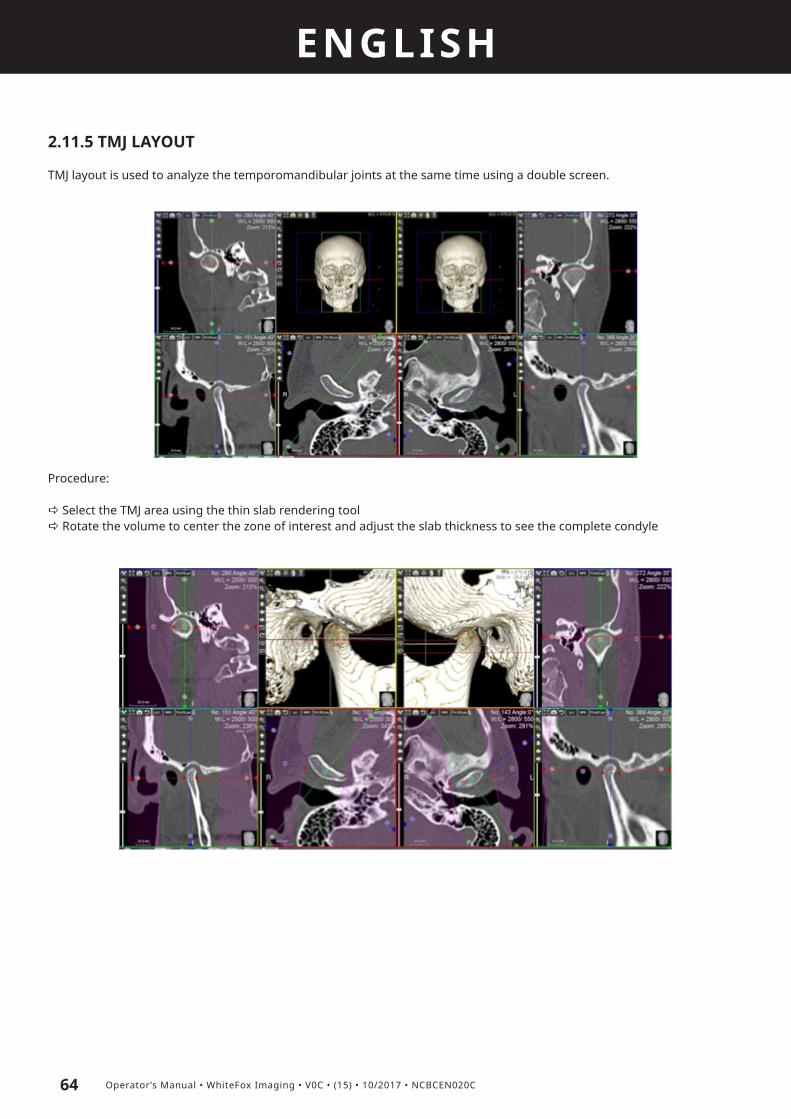
ENGLISH
64 Operator’s Manual • WhiteFox Imaging • V0C • (15) • 10/2017 • NCBCEN020C
2.11.5 TMJ LAYOUT
TMJ layout is used to analyze the temporomandibular joints at the same time using a double screen.
Procedure:
a Select the TMJ area using the thin slab rendering toola Rotate the volume to center the zone of interest and adjust the slab thickness to see the complete condyle

ENGLISH
65Operator’s Manual • WhiteFox Imaging • V0C • (15) • 10/2017 • NCBCEN020C
2.11.6 AIRWAYS LAYOUT
The Airways layout is focused on a set of tools for virtual endoscopy and volume calculation of airways and pipeline structures in generale (blood vessels,...).
Procedure:
a Trace a CPR line on the sagittal image following the airwaysa Click on OK to end the drawing part and click on the CPR view to start the endoscopic sessiona Adjust the camera settings according to the Fly tool options
2.12. REPORT TOOLSWhiteFox Imaging 4.0 can create two types of reports (dependent by the software version):
- Implant report- Radiology report
Implant report
After creating an implant planning, clicking on the report icon will open a pop up window asking for the following para-meters:
Clicking on OK the user can write the file name and location and confirm the action. A sample of the report is depicted below:

ENGLISH
66 Operator’s Manual • WhiteFox Imaging • V0C • (15) • 10/2017 • NCBCEN020C
Radiology report
WhiteFox Imaging 4.0 allows the radiologist to store images in a library while working on the dataset and compose these images in a custom report module. This module can be printed in 1:1 scale according to the installed printers.
Store single images in the Library:Every MPR/3D/Cross section view can be stored in the Image Library by retrieving the window option menu and selecting the “Add to Report Library” command.

ENGLISH
67Operator’s Manual • WhiteFox Imaging • V0C • (15) • 10/2017 • NCBCEN020C
Store multiple images in the Library:Multiple images can be stored in the Image Library by retrieving the window option menu and selecting the “Add Stack to Report Library...” command. A popup options window appears:
Choose the thickness of every image and the range, then click on CREATE button. Click on “Open Library” to access the Library directly without passing through the Layouts menu.
Store cross sections in the Library:Cross sections images can be stored in the Image Library by retrieving the window option menu and selecting the “Add to Report” command from the CPR window toolbar
Store images for Dentascan Reports:To export the images necessary to mix up a Dentascan an automatic option is available. To access this option go to the CPR Layout, draw the CPR curve and click on the CPR window option triangle and choose “Add Stack to Report Library...”
The following pop up window appears:

ENGLISH
68 Operator’s Manual • WhiteFox Imaging • V0C • (15) • 10/2017 • NCBCEN020C
The user can check the images he would like to include in the report, then click on EXPORT button to export them directly in the Library.
Report Library:Click on Layout menu and choose “Report Editor” to open it:
The procedure to correctly work with reports is the following:
a Choose a report template from the list (or create a new one using the Template Editor)a Choose the printer to set up the correct dimensions to print the report in 1:1 scale (or set the parameters manually)a Drag and drop the images in the corresponding places in the reporta Save/Print the report
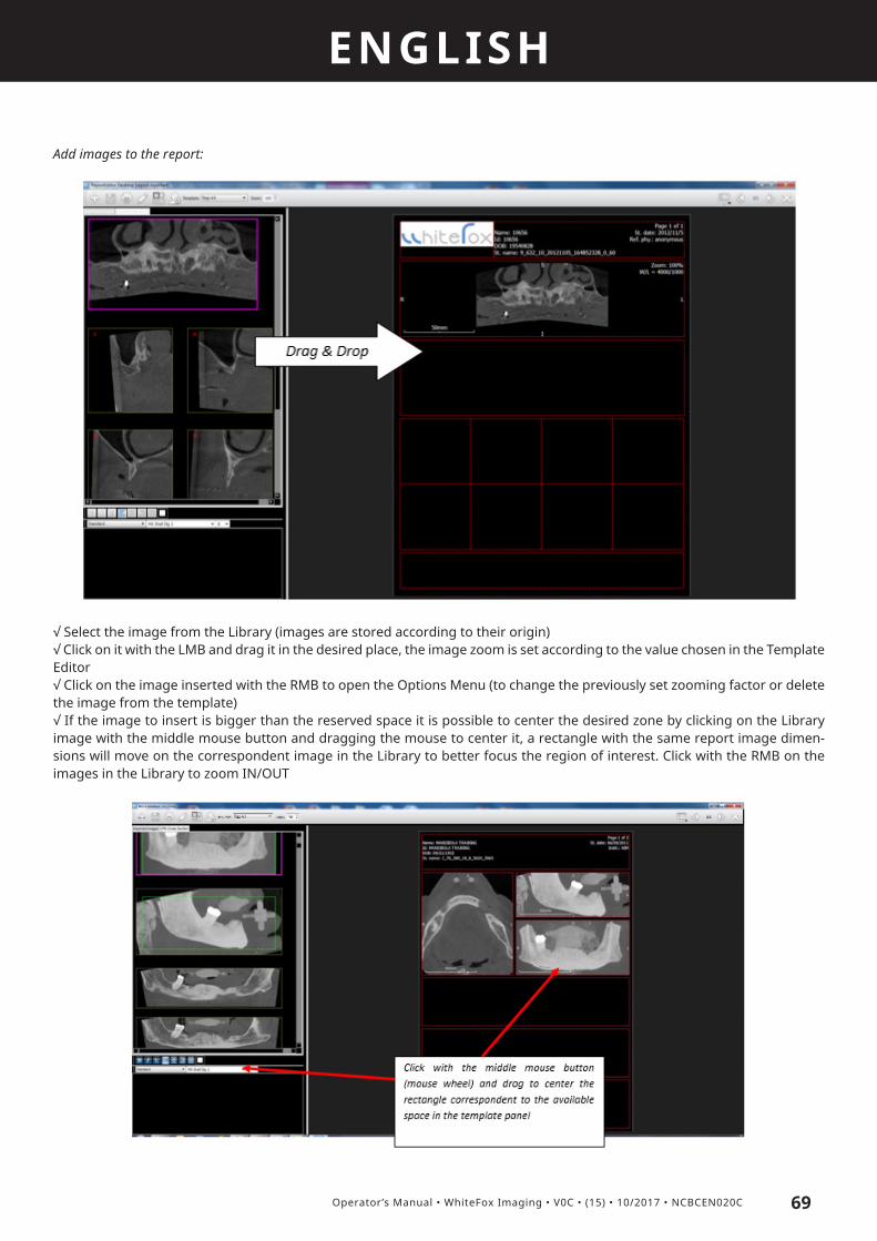
ENGLISH
69Operator’s Manual • WhiteFox Imaging • V0C • (15) • 10/2017 • NCBCEN020C
Add images to the report:
√ Select the image from the Library (images are stored according to their origin)√ Click on it with the LMB and drag it in the desired place, the image zoom is set according to the value chosen in the Template Editor√ Click on the image inserted with the RMB to open the Options Menu (to change the previously set zooming factor or delete the image from the template)√ If the image to insert is bigger than the reserved space it is possible to center the desired zone by clicking on the Library image with the middle mouse button and dragging the mouse to center it, a rectangle with the same report image dimen-sions will move on the correspondent image in the Library to better focus the region of interest. Click with the RMB on the images in the Library to zoom IN/OUT

ENGLISH
70 Operator’s Manual • WhiteFox Imaging • V0C • (15) • 10/2017 • NCBCEN020C
√ Inserting a CPR image will draw its reference lines on scout and correspondent axial views
√ Inserting a cross section image will draw its reference lines and number on CPR and the correspondent axial view. To select multiple cross sections click on the them with the LMB; clicking with the RMB on a cross section will deselect all the images.
√ Click on IMPORT IMAGE button to add an external image file to the library, a new window will pop up to select the image. The imported image will be automatically fitted to the dimensions of the available space in the report√ Click on EDIT HEADER button to change the patient data (taken automatically from the DICOM dataset values) or add/change the logo on the report

ENGLISH
71Operator’s Manual • WhiteFox Imaging • V0C • (15) • 10/2017 • NCBCEN020C
Additional options:Additional options on the report layout can be set in the SETTINGS menuAll the cross section reference lines are shown in the axial and CPR view by default. The user can modify this setting by choo-sing to show the reference numbers on a defined step.
In the same panel it’s possible to show/hide measurements, 3D objects and teeth number labels on the report.
Save and print the report:
Click on SAVE REPORT to store the report library in a proprietary file format. Click on PRINT to send the report to the selected printer.
The report scale depends from the printer/paper settings and might not be in 1:1 scale, check the image rulers for reference.
How to use the Template Editor:
The Template Editor enables the user to build complete custom report starting from the existing library or by creating them from scratch. The Editor layout appears as follows:

ENGLISH
72 Operator’s Manual • WhiteFox Imaging • V0C • (15) • 10/2017 • NCBCEN020C
The correct procedure to set up a new template is the following:
a Choose the printer and the paper format (through the Printer Settings button)a Insert the new template name and save it (“Save as...” button will save a copy of it if the user is modifying an existing report)a Set the font color and size, choose the background and image borders colorsa Set the “Grid distance” value, since the report objects will snap to the grid points, it is suggested to use a small grid distance (1-2 mm) to create nicely aligned reportsa Start adding objects in the following order: Logo, header, comment, images and cross sections (suggestion)a Click with the LMB on the object and drag it in the desired position. Double clicking on it will snap it to the nearest point in the grida Click with the RMB on the object to set its properties (type, zoom factor)
a If the selected object is a cross section the user can decide the number of rows and columns through the options menu and drag the square borders to set the dimensions

ENGLISH
73Operator’s Manual • WhiteFox Imaging • V0C • (15) • 10/2017 • NCBCEN020C
HARDWARE REQUIREMENTSBefore running the WhiteFox Imaging software, please check if your computer corresponds to the WhiteFox Imaging hard-ware requirements. Note that the hardware which does not meet the requirements might affect the software’s performance, especially its speed, but it might as well disable the features which require more RAM and a better processor.
3.1. MOUSEMouse takes charge of inputting information together with the keyboard. The recommendation is 3 button type mouse with the scroll wheel (which can be used as middle button). Separate mouse driver software is not required.
3.2. KEYBOARDSeparate keyboard software is not necessary.
Note: If the software is used in environments which have to meet high hygienic requirement, we recommend the use of keyboards and mice completely disinfectable (InduProof™ - contact de Götzen® S.r.l. (Acteon Group) for more information).
3.3. MONITORWe recommend high-resolution monitor to facilitate image contrast.Monitor takes charge of outputting user information together with printer. The monitor type and resolution has to be set in Microsoft Windows or Macintosh O/S. For further details, refer to the monitor installation information.
3.4. SYSTEM COMPONENTS• CPU: Intel Core 2 Duo or I5. For best performance we suggest Intel I7• RAM: minimum 2 GB, for stacks of images including a skull 4GB is recommended• Hard disk: 300 - 500 GB (for the storage of images, the software only takes about 100 MB)• Graphic card: Nvidia Geforce series is recommended (price range 150-200€). For maximum performance Nvidia GTX family• O/S: MS Windows XP/7 - Apple O/S• Monitor resolution: starting from 1024 x 768For Mac users:• MacBook Pro (13» - 17») or iMac
Please consult our support team regarding specific hardware requirements and recommendations, since these are only general recommendations.
3

2460
de Götzen S.r.l • A company of ACTEON Group Via Roma 45 • 21057 OLGIATE OLONA (VARESE) • ITALY
Tel +39 0331 376 760 • Fax +39 0331 376 763 E-mail: [email protected] •www.acteongroup.com