OPERATOR MANUAL - Heartland Medical€¦ · 4.3 Reverse Patient Orientation ... Table of Contents...
60
OPERATOR MANUAL Cmax™ Surgical Table (03/16/09) P150830-685
Transcript of OPERATOR MANUAL - Heartland Medical€¦ · 4.3 Reverse Patient Orientation ... Table of Contents...

OPERATOR MANUAL
Cmax™ Surgical Table
(03/16/09) P150830-685

iIntroduction Operator Manual 150830-685
A WORD FROM STERIS CORPORATION
©2009, STERIS Corporation. All rights reserved. Printed in U.S.A.
IMPORTANT: Read this entire manual before attempting toinstall or operate your Cmax™ Surgical Table. Ensure allappropriate personnel understand the contents of this manual.
This Operating Manual contains important information on proper useand maintenance of the Cmax Surgical Table. All personnelinvolved in the use and maintenance of this equipment mustcarefully review and comply with the warnings, cautions, andinstructions contained in this manual. These instructions areimportant to protect the health and safety of personnel operating thetable and should be retained in a conveniently accessible area forquick reference.
Complete instructions for uncrating have been furnished. If missing,contact STERIS for a replacement copy, giving the serial, equipmentand model numbers of the unit.
STERIS carries a complete line of accessories for use with this table.STERIS representatives will gladly review these with you.
Advisory A listing of the SAFETY PRECAUTIONS to be observed when operatingand servicing this Cmax Surgical Table is found in SECTION 1 of thismanual. Do not operate or service the equipment until you havebecome familiar with this information.
Any alteration of the surgical table not authorized or performed bySTERIS will void the warranty, could adversely affect operator safetyand could violate national, state and local regulations.
Indications for Use The Cmax Surgical Table is designed for most surgical procedureswith unrestricted radiological access without patient reversing.
Service Information A thorough preventive maintenance program is essential for safe andproper unit operation. This manual contains maintenance schedulesand procedures which should be followed for satisfactory equipmentperformance. Comprehensive instructions for monthly, quarterly andsemi-annual preventive maintenance can be found in the MaintenanceManual (available from STERIS).
Only STERIS-trained personnel should attempt to performmaintenance on the Cmax Surgical Table to avoid personal injury,improper equipment performance, invalidation of the equipmentwarranty or other costly damage.

ii150830-685 Operator Manual Introduction
Customers are encouraged to contact STERIS concerning our comprehensivepreventive maintenance agreement. Under the terms of this agreement,preventive maintenance, adjustments and replacement of worn parts areprovided on a scheduled basis to help ensure optimal equipment performanceand help avoid untimely or costly interruptions. STERIS maintains a global staffof well equipped, factory-trained technicians to provide these services, as wellas expert repair services. Please contact STERIS for details.
NOTE: A patient grounding post/potential equalization terminal (maleconnector, DIN 42801) is provided. The female connector for patientgrounding is not furnished by STERIS.
iiiIntroduction Operator Manual 150830-685
Manufactured by:STERIS Corporation2720 Gunter Park EastMontgomery, AL 36109 • USATEL: 334 277 6660FAX: 334 271 5450www.steris.com
Class 1 EquipmentType B Equipment
Splash-Proof Equipment (enclosed equipment protected against splashingwater, IPX4)
Equipment not suitable for use in the presence of a flammableanesthetic mixture with air or oxygen or nitrous oxide.
Suitable for intermittent operation 3 min/hr.
EC Authorized Representative
STERIS LimitedSTERIS HouseJays CloseViablesBasingstokeHampshireRG22 4AXUNITED KINGDOM
The base language of this document isENGLISH. Any translations must be
made from the base language document.
Manufactured by:STERIS Surgical Technologies SAS645, rue des ChâtaigniersBAT 405-B2-F45774 Saran CedexFRANCE+ 33 2 38 74 54 00
vTable of Contents Operator Manual P150830-685
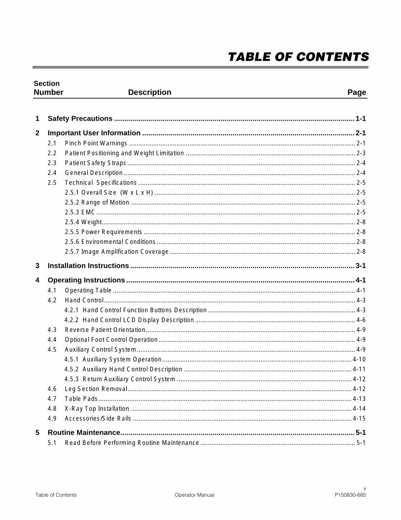
TABLE OF CONTENTS
Section Number Description Page
1 Safety Precautions ........................................................................................................................ 1-1
2 Important User Information .......................................................................................................... 2-12.1 Pinch Point Warnings ............................................................................................................................ 2-1
2.2 Patient Positioning and Weight Limitation ............................................................................................. 2-3
2.3 Patient Safety Straps ............................................................................................................................. 2-4
2.4 General Description ............................................................................................................................... 2-4
2.5 Technical Specifications ....................................................................................................................... 2-5
2.5.1 Overall Size (W x L x H) .............................................................................................................. 2-5
2.5.2 Range of Motion ........................................................................................................................... 2-5
2.5.3 EMC.............................................................................................................................................. 2-5
2.5.4 Weight........................................................................................................................................... 2-8
2.5.5 Power Requirements .................................................................................................................... 2-8
2.5.6 Environmental Conditions............................................................................................................. 2-8
2.5.7 Image Amplification Coverage...................................................................................................... 2-8
3 Installation Instructions ................................................................................................................ 3-1
4 Operating Instructions .................................................................................................................. 4-14.1 Operating Table ..................................................................................................................................... 4-1
4.2 Hand Control.......................................................................................................................................... 4-3
4.2.1 Hand Control Function Buttons Description ................................................................................. 4-3
4.2.2 Hand Control LCD Display Description ........................................................................................ 4-6
4.3 Reverse Patient Orientation................................................................................................................... 4-9
4.4 Optional Foot Control Operation............................................................................................................ 4-9
4.5 Auxiliary Control System........................................................................................................................ 4-9
4.5.1 Auxiliary System Operation........................................................................................................ 4-10
4.5.2 Auxiliary Hand Control Description ............................................................................................ 4-11
4.5.3 Return Auxiliary Control System ................................................................................................ 4-12
4.6 Leg Section Removal........................................................................................................................... 4-12
4.7 Table Pads........................................................................................................................................... 4-13
4.8 X-Ray Top Installation ......................................................................................................................... 4-14
4.9 Accessories/Side Rails ........................................................................................................................ 4-15
5 Routine Maintenance..................................................................................................................... 5-15.1 Read Before Performing Routine Maintenance ..................................................................................... 5-1

viP150830-685 Operator Manual Table of Contents
Section Number Description Page
TABLE OF CONTENTS (CONT’D)
5.2 Cleaning Table....................................................................................................................................... 5-2
5.2.1 General ........................................................................................................................................ 5-2
5.2.2 After Each Usage ......................................................................................................................... 5-3
5.2.3 End-of-Day Cleaning Procedure .................................................................................................. 5-4
5.2.4 Weekly Cleaning Procedure......................................................................................................... 5-4
5.3 Bi-Weekly Maintenance ......................................................................................................................... 5-4
5.4 Monthly Maintenance............................................................................................................................. 5-4
5.5 Battery Charging Procedure .................................................................................................................. 5-5
5.6 Preventive Maintenance Schedule ........................................................................................................ 5-7
5.7 Replacement Parts ................................................................................................................................ 5-8
5.8 ALS Check............................................................................................................................................. 5-9
5.9 LEVEL Check ...................................................................................................................................... 5-10
5.10 Auxiliary Control Check ....................................................................................................................... 5-10
6 Troubleshooting ............................................................................................................................ 6-1
7 Disposal Hazards........................................................................................................................... 7-1
viiTable of Contents Operator Manual P150830-685
LIST OF FIGURES
Description Page
Figure 2-1. Pinch Points.........................................................................................................................................2-1
Figure 2-2. Pinch Points.........................................................................................................................................2-2
Figure 2-3. Cmax Surgical Table Components (Typical) .......................................................................................2-6
Figure 2-4. Cmax Surgical Table Range of Motion (Typical) .................................................................................2-7
Figure 2-5. Cmax Tabletop Dimensions (Typical)..................................................................................................2-8
Figure 2-6. Cmax Surgical Table Image Amplification Coverage ..........................................................................2-9
Figure 3-1. Install/Remove Battery Fuse ...............................................................................................................3-2
Figure 3-2. Connect Cmax Surgical Table to Facility Power..................................................................................3-3
Figure 3-3. Connect Hand Control to Cmax Surgical Table...................................................................................3-4
Figure 3-4. Connect Panel .....................................................................................................................................3-5
Figure 3-5. Connect Optional Foot Control to Cmax Surgical Table......................................................................3-5
Figure 3-6. Install Head Section.............................................................................................................................3-6
Figure 3-7. Hand Control LCD Display ..................................................................................................................3-6
Figure 3-8. Attaching Leg Section..........................................................................................................................3-7
Figure 4-1. Cmax Surgical Table ...........................................................................................................................4-1
Figure 4-2. Head Section Operation (Typical) .......................................................................................................4-2
Figure 4-3. Cmax Surgical Table Hand Control .....................................................................................................4-4
Figure 4-4. Hand Control LCD Display ..................................................................................................................4-8
Figure 4-5. Auxiliary Control System ...................................................................................................................4-10
Figure 4-6. Auxiliary Hand Control .......................................................................................................................4-12
Figure 4-7. Leg Section Removal ........................................................................................................................4-13
Figure 4-8. Tabletop Pads ...................................................................................................................................4-14
Figure 4-9. X-Ray Top Installation .......................................................................................................................4-15
Figure 5-1. INTELLIPOWER Panel LED Display ...................................................................................................5-6

ixTable of Contents Operator Manual P150830-685
LIST OF TABLES
Table Title Page
Table 1-1. Definition of Symbols on Surgical Table.......................................................................................... 1-5
Table 4-1. Cmax Surgical Table Specific Accessories ................................................................................... 4-16
Table 5-1 Recommended Cleaning Products.................................................................................................. 5-2
Table 5-2 Preventive Maintenance Schedule for Cmax Surgical Table .......................................................... 5-7
Table 5-3. Replacement Parts.......................................................................................................................... 5-9
Table 6-1 Troubleshooting Chart..................................................................................................................... 6-2
Table 6-2. Troubleshooting Chart (LCD Message)........................................................................................... 6-3

1-1Safety Precautions Operating Manual 150830-685
1
The following Safety Precautions must be observed when operating or servicing this Cmax™ Surgical Table.WARNING indicates the potential for personal injury and CAUTION indicates the potential for damage to equip-ment. For emphasis, certain Safety Precautions are repeated throughout the manual. It is important to reviewALL Safety Precautions before operating or servicing the unit.
WARNING – PINCHING HAZARD:
WARNING – TIPPING HAZARD:
WARNING – EXPLOSION HAZARD:
WARNING – TRIPPING HAZARD:
Pinch points are created during tabletop articulation. Carefully review illustrations in Figure 2-1 andFigure 2-2 before operating the table.
To avoid serious injury, keep limbs, fingers and other body areas clear of all pinch points whenpositioning the table.
When manually positioning table sections, stay clear of potential pinching hazards.
Do not place patient on the table unless floor locks are engaged.
Do not disengage floor locks when patient is on table.
Do not use this table for patients exceeding the maximum patient weight (patient in normal orientation)of 1100 lb (499 kg) without patient posturing or tabletop slide (except raise/lower), 1000 lb (454 kg) withpatient posturing (except tabletop slide), or 600 lb (272 kg) with full patient posturing (includingtabletop slide).
Center tabletop over column before applying chest compressions.
Center tabletop over column before transferring patient on or off of table.
Table must not be used in the presence of flammable anesthetics.
Route the power cord to the receptacle in a position so that it will not be tripped over by personnel in thearea.
SAFETY PRECAUTIONS 1

1-2150830-685 Operating Manual Safety Precautions
WARNING – PERSONAL INJURY HAZARD:
WARNING – INSTABILITY HAZARD:
WARNING – PINCHING AND TIPPING HAZARD:
Failure to keep the patient properly secured with the patient safety straps at all times could result indeath or serious injury to the patient and the operating room staff.
The floor locks must be engaged at all times when a patient is on the table. Failure to engage the floorlocks before placing a patient on the table or disengaging the floor locks while a patient is on the tablecould result in the table rolling unexpectedly during the procedure.
Keep hands and feet clear of the unloading platform and the table base when unloading the table.Serious personal injury could result.
Section 4.1, Steps 1-6 in "Operating Table" must be executed before patient transfer to the table.Execution of Steps 1-6 with the patient on the table could result in injury to both the patient and theoperating room staff.
Healthcare professionals must ensure patients are positioned and monitored so as to preventcompromising respiration, nerve pathways or circulation.
When installing any table accessory, check for correct attachment and tighten securely (if appropriate).Do not use a worn or damaged accessory. Check installation before using any accessory.
Unanticipated table movement could cause patient injury. Patient must be secured to the table inaccordance with recommended positioning practices.
When cleaning/disinfecting table, do not use phenolics which may cause patient skin burns ifinadequately rinsed off, or alcohol, which does not have sufficient cleaning/disinfecting properties.
The table leg section is designed to support the patient legs. Do not put body weight on the legsection.
If the integrity of the external protective ground installation or arrangement is in doubt, operate the tablefrom its internal power source.
If an antistatic path is necessary, STERIS recommends antistatic pads (specifically developed for thistable) in direct contact with the patient. Table must also be positioned on antistatic floor or connected toequalization device (equipotential connector).
Do not remove table leg section if patient is not properly positioned. Patient's torso and buttocks mustbe firmly held in place by table back and seat sections and legs supported by leg supports.
Possible patient or user injury, as well as table or accessory failure, may result from using STERIS tableaccessories for other than their stated purpose – or from using, on STERIS tables, accessoriesmanufactured and sold by other companies.
Patient injury may result if the operator of this table is not completely familiar with the controls for patientpositioning and table operation.
1-3Safety Precautions Operating Manual 150830-685
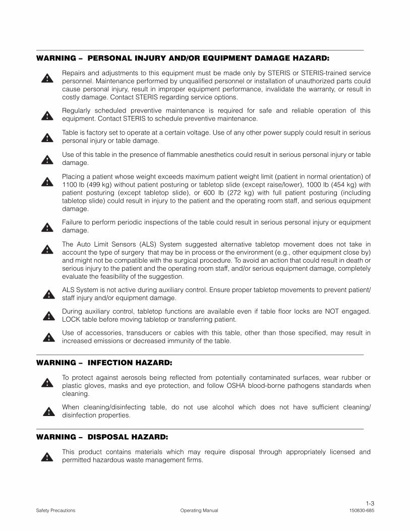
WARNING – PERSONAL INJURY AND/OR EQUIPMENT DAMAGE HAZARD:
WARNING – INFECTION HAZARD:
WARNING – DISPOSAL HAZARD:
Repairs and adjustments to this equipment must be made only by STERIS or STERIS-trained servicepersonnel. Maintenance performed by unqualified personnel or installation of unauthorized parts couldcause personal injury, result in improper equipment performance, invalidate the warranty, or result incostly damage. Contact STERIS regarding service options.
Regularly scheduled preventive maintenance is required for safe and reliable operation of thisequipment. Contact STERIS to schedule preventive maintenance.
Table is factory set to operate at a certain voltage. Use of any other power supply could result in seriouspersonal injury or table damage.
Use of this table in the presence of flammable anesthetics could result in serious personal injury or tabledamage.
Placing a patient whose weight exceeds maximum patient weight limit (patient in normal orientation) of1100 lb (499 kg) without patient posturing or tabletop slide (except raise/lower), 1000 lb (454 kg) withpatient posturing (except tabletop slide), or 600 lb (272 kg) with full patient posturing (includingtabletop slide) could result in injury to the patient and the operating room staff, and serious equipmentdamage.
Failure to perform periodic inspections of the table could result in serious personal injury or equipmentdamage.
The Auto Limit Sensors (ALS) System suggested alternative tabletop movement does not take inaccount the type of surgery that may be in process or the environment (e.g., other equipment close by)and might not be compatible with the surgical procedure. To avoid an action that could result in death orserious injury to the patient and the operating room staff, and/or serious equipment damage, completelyevaluate the feasibility of the suggestion.
ALS System is not active during auxiliary control. Ensure proper tabletop movements to prevent patient/staff injury and/or equipment damage.
During auxiliary control, tabletop functions are available even if table floor locks are NOT engaged.LOCK table before moving tabletop or transferring patient.
Use of accessories, transducers or cables with this table, other than those specified, may result inincreased emissions or decreased immunity of the table.
To protect against aerosols being reflected from potentially contaminated surfaces, wear rubber orplastic gloves, masks and eye protection, and follow OSHA blood-borne pathogens standards whencleaning.
When cleaning/disinfecting table, do not use alcohol which does not have sufficient cleaning/disinfection properties.
This product contains materials which may require disposal through appropriately licensed andpermitted hazardous waste management firms.
1-4150830-685 Operating Manual Safety Precautions
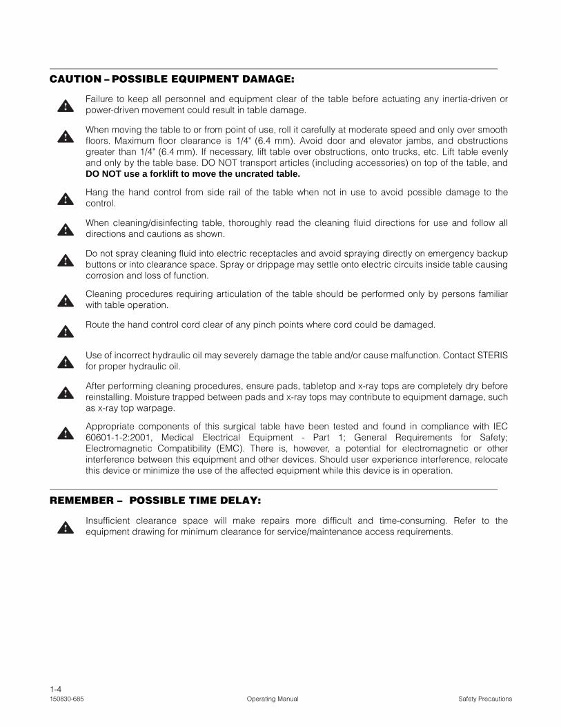
CAUTION – POSSIBLE EQUIPMENT DAMAGE:
REMEMBER – POSSIBLE TIME DELAY:
Failure to keep all personnel and equipment clear of the table before actuating any inertia-driven orpower-driven movement could result in table damage.
When moving the table to or from point of use, roll it carefully at moderate speed and only over smoothfloors. Maximum floor clearance is 1/4" (6.4 mm). Avoid door and elevator jambs, and obstructionsgreater than 1/4" (6.4 mm). If necessary, lift table over obstructions, onto trucks, etc. Lift table evenlyand only by the table base. DO NOT transport articles (including accessories) on top of the table, andDO NOT use a forklift to move the uncrated table.
Hang the hand control from side rail of the table when not in use to avoid possible damage to thecontrol.
When cleaning/disinfecting table, thoroughly read the cleaning fluid directions for use and follow alldirections and cautions as shown.
Do not spray cleaning fluid into electric receptacles and avoid spraying directly on emergency backupbuttons or into clearance space. Spray or drippage may settle onto electric circuits inside table causingcorrosion and loss of function.
Cleaning procedures requiring articulation of the table should be performed only by persons familiarwith table operation.
Route the hand control cord clear of any pinch points where cord could be damaged.
Use of incorrect hydraulic oil may severely damage the table and/or cause malfunction. Contact STERISfor proper hydraulic oil.
After performing cleaning procedures, ensure pads, tabletop and x-ray tops are completely dry beforereinstalling. Moisture trapped between pads and x-ray tops may contribute to equipment damage, suchas x-ray top warpage.
Appropriate components of this surgical table have been tested and found in compliance with IEC60601-1-2:2001, Medical Electrical Equipment - Part 1; General Requirements for Safety;Electromagnetic Compatibility (EMC). There is, however, a potential for electromagnetic or otherinterference between this equipment and other devices. Should user experience interference, relocatethis device or minimize the use of the affected equipment while this device is in operation.
Insufficient clearance space will make repairs more difficult and time-consuming. Refer to theequipment drawing for minimum clearance for service/maintenance access requirements.
1-5Safety Precautions Operating Manual 150830-685
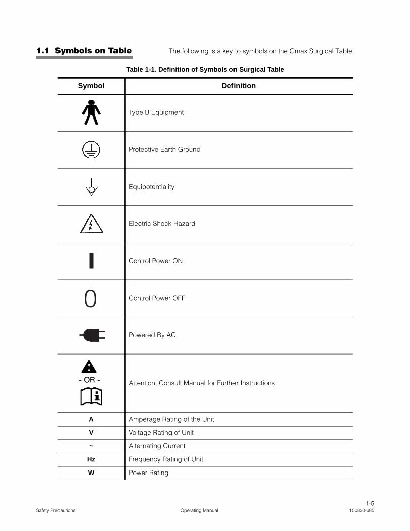
1.1 Symbols on Table The following is a key to symbols on the Cmax Surgical Table.
Table 1-1. Definition of Symbols on Surgical Table
Symbol Definition
Type B Equipment
Protective Earth Ground
Equipotentiality
Electric Shock Hazard
Control Power ON
Control Power OFF
Powered By AC
Attention, Consult Manual for Further Instructions
A Amperage Rating of the Unit
V Voltage Rating of Unit
~ Alternating Current
Hz Frequency Rating of Unit
W Power Rating
0
- OR -- OR -- OR -- OR -- OR -

1-6150830-685 Operating Manual Safety Precautions
SNIPX4
Serial Number of the UnitSplash-Proof Equipment
INTELLIPOWER® Dual Power System Power Panel(Battery Charge/Discharge Status)
Powered By Battery
Table 1-1. Definition of Symbols on Surgical Table (Cont’d)
Symbol Definition
CHARGE BATTERY
INTELLI POWER

2-1Important User Information Operator Manual 150830-685
2.1 Pinch PointWarnings
When inertia-driven or power-driven table parts close (especiallyduring extreme tabletop articulation), pinch-point hazards exist (seeFigure 2-1). All personnel involved in tabletop positioning shouldexamine and be aware of these points before operating the Cmax™
Surgical Table.
Pinch points shown (circled) in Figure 2-1:
1. Between Head Section and Base Cover.
2. Between Leg Section and Floor.
3. Between Leg Section and Column Cover.
4. Between Leg Section and Base Cover.
Figure 2-1. Pinch Points
Pinch points shown (circled) in Figure 2-2:
1. Between Kidney™ Elevator Mechanism and Seat Section.
2. Between Leg Section and Seat Section.
3. Side Rail Lock.
4. Between Back Section and Seat Section.
5. Between Head Section and Back Section.
WARNING – PINCHING HAZARD:
• Pinch points are created during tabletop articulation. Carefully review illustrations in Figure 2-1 and Figure 2-2 before operating the table.
• To avoid serious injury, keep limbs, fingers and other body areas clear of all pinch points when positioning the table.
CAUTION – POSSIBLE EQUIPMENT DAMAGE: Failure to keep all personnel and equipment clear of the table before actuating any inertia-driven or power-driven movement could result in table damage.
C-M
AX
36
C-M
AX
29
C-M
AX
30
C-M
AX
31
FIG. 3.2 PINCH POINTS
1 2
34
WARNING – PINCHING HAZARD:
• Pinch points are created during tabletop articulation. Carefully review illustra-tions in Figure 2-1 and 2-2 before operating the table.
• To avoid serious injury, keep limbs, fingers and other body areas clear of all pinch points when positioning the table.
IMPORTANT USER INFORMATION 2

2-2150830-685 Operator Manual Important User Information
Figure 2-2. Pinch Points
WARNINGAVERTISSEM
ENT
CHARGE
BATTERY
INTELLI POWER
WARNINGAVERTISSEM
ENT
W0109-2000-SW
FDLKM-C.M
AX
Ensurecaps cover
sockets when not in use.
SERVE
C-M
AX
07
FIG. 3.1 PINCH POINTS
1
23
4
5

2-3Important User Information Operator Manual 150830-685
2.2 Patient Positioningand Weight Limitation
NOTE: Accessories may have a specified weight limitation that is lessthan that of the table. Do not exceed the lowest weight limit, table oraccessory.
The Cmax General Surgical Table is designed to safely support (withpatient in normal orientation): 1100 lb (499 kg) without patientposturing or tabletop slide (except raise/lower); 1000 lb (454 kg) fullpatient posturing (except tabletop slide); 600 lb (272 kg) full patientposturing (including tabletop slide). Do not exceed the maximumpatient weight.
NOTE: When positioning the patient on the table, note the following:
1) Always check patient stability when patient is positioned.
2) Do not place patient on the table unless floor locks are engaged.
3) Use extreme care when transferring patients to or from table.
4) Ensure all accessories are properly installed and secured.
5) Check for and eliminate harmful patient pressure points once patient is positioned.
6) Have a qualified medical professional monitor patient during surgery for all possible patient positioning hazards.
7) Do not place patient weight on the Leg Section. Leg Section is designed to support leg weight, not body weight.
All patients must be restrained for proper safety regardless of thelength or type of procedure.
NOTE: STERIS recommends only using STERIS manufactured ordistributed accessories with this table. If an accessory from anothermanufacturer is used, it is the user’s responsibility to ensure theaccessory is compatible with the table and not dangerous to the patientand/or surgical staff.
WARNING – TIPPING HAZARD:
• Do not place patient on the table unless floor locks are engaged.
• Do not use this table for patients exceeding the maximum patient weight (patient in normal orientation) of 1100 lb (499 kg) without patient posturing or tabletop slide (except raise/lower), 1000 lb (454 kg) with patient posturing (except tabletop slide), or 600 lb (272 kg) with full patient posturing (including tabletop slide).
WARNING – PERSONAL INJURY HAZARD:
• The floor locks must be engaged at all times when a patient is on the table. Failure to engage the floor locks before placing a patient on the table or disengaging the floor locks while a patient is on the table could result in the table rolling unexpectedly during the procedure.
• Healthcare professionals must ensure patients are positioned and monitored so as to prevent compro-mising respiration, nerve pathways or circulation.

2-4150830-685 Operator Manual Important User Information
2.3 Patient SafetyStraps
Adjust the patient safety straps such that they restrain the patientaccording to currently accepted patient restraining practices, keepingin mind the Trendelenburg/Reverse Trendelenburg, back, lateral tiltand height adjustment.
2.4 GeneralDescription
The Cmax Surgical Table (see Figure 2-3) is a mobile,electrohydraulically operated surgical table specifically designed toprovide the complete patient positioning flexibility required for modernsurgical care facilities. The Cmax Surgical Table features poweredlateral tilt, Trendelenburg/Reverse Trendelenburg and adjustableheight functions. This table is designed to safely function with patientsnot exceeding the maximum patient weight limit (patient in normalorientation) of 1100 lb (499 kg) without patient posturing or tabletopslide (except raise/lower); 1000 lb (454 kg) full patient posturing(except tabletop slide);600 lb (272 kg) full patient posturing (includingtabletop slide) and is constructed of aluminum alloy, stainless steeland other high quality materials. The Cmax Surgical Table isequipped with a large sliding table top providing unrestrictedradiological access without patient reversing.
The Cmax Surgical Table is powered by either internal battery orfacility electric through use of the patent-pending INTELLIPOWER®
dual power system.
The table accepts positioning commands from three sources:
1. A hand control (which includes “FLEX”, "REFLEX", "SLIDE HEAD", "SLIDE FOOT", "OFF", "Trend.”, "REV. TREND", “Height UP”, "HEIGHT DOWN", “TILT LEFT”, "TILT RIGHT", "BACK DOWN", "BACK UP", "LEG DOWN" , "LEG UP", "KIDNEY UP", "KIDNEY DOWN", "LEVEL", "REV. ORIENT" and "FLOOR LOCK". Refer to Figure 4-3 of this document for control feature locations.
2. An optional physician-controlled foot control (which includes Trendelenburg Tilts, Lateral Tilts and Height functions). Refer to SECTION 4.4, OPTIONAL FOOT CONTROL OPERATION.
3. An Auxiliary Control System permits table operation in the event of primary control malfunction (refer to SECTION 4.5, AUXILIARY CONTROL SYSTEM).
NOTE: The Head Section is manually adjustable.
* SAE Measurements are approximate based on metric dimensions.
WARNING – PERSONAL INJURY HAZARD: Failure to keep the patient properly secured with the patient safety straps at all times could result in death or serious injury to the patient and the operating room staff.
CAUTION – POSSIBLE EQUIPMENT DAMAGE: Appropriate components of this surgical table have been tested and found in compliance with IEC 60601-1-2:2001, Medical Electrical Equipment - Part 1; General Requirements for Safety; Electromagnetic Compatibility (EMC). There is, however, a potential for electromagnetic or other interference between this equipment and other devices. Should user experience interference, relocate this device or minimize the use of the affected equipment while this device is in operation.
2-5Important User Information Operator Manual 150830-685
2.5 TechnicalSpecifications
See Figure 2-4 through Figure 2-6.
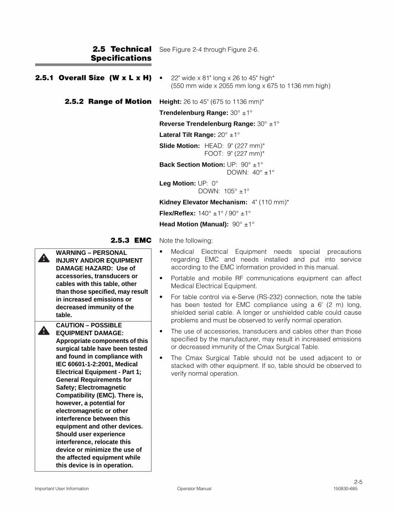
2.5.1 Overall Size (W x L x H) • 22" wide x 81" long x 26 to 45" high*(550 mm wide x 2055 mm long x 675 to 1136 mm high)
2.5.2 Range of Motion Height: 26 to 45" (675 to 1136 mm)*
Trendelenburg Range: 30° ±1°
Reverse Trendelenburg Range: 30° ±1°
Lateral Tilt Range: 20° ±1°
Slide Motion: HEAD: 9" (227 mm)*FOOT: 9" (227 mm)*
Back Section Motion: UP: 90° ±1°DOWN: 40° ±1°
Leg Motion: UP: 0° DOWN: 105° ±1°
Kidney Elevator Mechanism: 4" (110 mm)*
Flex/Reflex: 140° ±1° / 90° ±1°
Head Motion (Manual): 90° ±1°
2.5.3 EMC Note the following:
• Medical Electrical Equipment needs special precautionsregarding EMC and needs installed and put into serviceaccording to the EMC information provided in this manual.
• Portable and mobile RF communications equipment can affectMedical Electrical Equipment.
• For table control via e-Serve (RS-232) connection, note the tablehas been tested for EMC compliance using a 6’ (2 m) long,shielded serial cable. A longer or unshielded cable could causeproblems and must be observed to verify normal operation.
• The use of accessories, transducers and cables other than thosespecified by the manufacturer, may result in increased emissionsor decreased immunity of the Cmax Surgical Table.
• The Cmax Surgical Table should not be used adjacent to orstacked with other equipment. If so, table should be observed toverify normal operation.
WARNING – PERSONAL INJURY AND/OR EQUIPMENT DAMAGE HAZARD: Use of accessories, transducers or cables with this table, other than those specified, may result in increased emissions or decreased immunity of the table.
CAUTION – POSSIBLE EQUIPMENT DAMAGE: Appropriate components of this surgical table have been tested and found in compliance with IEC 60601-1-2:2001, Medical Electrical Equipment - Part 1; General Requirements for Safety; Electromagnetic Compatibility (EMC). There is, however, a potential for electromagnetic or other interference between this equipment and other devices. Should user experience interference, relocate this device or minimize the use of the affected equipment while this device is in operation.

2-6150830-685 Operator Manual Important User Information
Figure 2-3. Cmax Surgical Table Components (Typical)
WARNINGAVERTISSEM
ENT
CHARGE
BATTERY
INTELLI POWER
WARNINGAVERTISSEM
ENT
W0109-2000-SW
FDLKM-C.M
AX
Ensurecaps cover
sockets when not in use.
SERVE
1
2
3
5
6
4
8
14
12
7
03"
00"20¡
T
00¡
TREND
TILT
00¡
SLIDE HEAD
!
-04¡ 13
10
11
FIG. 4.1.2 - DESCRIPTION
9 15
CHARGE BATTERY
INTELLI POWER
16 17
KEY:1. Table Base 11. Intellipower Dual Power System Display2. Column 12. Connection Panel3. Tabletop 13. Hand Control4. Head Section 14. Auxiliary Control System5. Back Section 15. Ground Equalization Terminal (Male Connection)6. Kidney Elevator Mechanism 16. Electrical Characteristics Label7. Seat Section (Sliding) 17. Data Plate8. Leg Section 18. Primary Fuses9. Power Panel 19. Main Power Switch10. Power Cord 20. AC Receptacle
2019 1816 17
11

2-7Important User Information Operator Manual 150830-685
Figure 2-4. Cmax Surgical Table Range of Motion (Typical)
26(675)
45(1136)
9 (227)
9 (227)
Dimensions are inches (mm). SAE measurements are approximatebased on metric dimensions.
90°
40°105°
90°
90°
30°
30°
20°
20°4 (110)
90°
2(51)
140°

2-8150830-685 Operator Manual Important User Information
2.5.4 Weight • Table: 560 lb (250 kg)Maximum Patient Weight (patient in normal orientation): 1100 lb(499 kg) without patient posturing or tabletop slide (except raise/lower); 1000 lb (454 kg) full patient posturing (except tabletopslide);600 lb (272 kg) full patient posturing (including tabletopslide).
2.5.5 Power Requirements Line Power Input:
• 100-240 Vac, One-Phase, 50/60 Hz, 4.0 Amp
NOTE: Each table is shipped from the factory configured to theelectrical requirement specified on the factory order. If this electricalconfiguration needs to be changed in the field,consult STERIS for theneeded procedure and required materials.
2.5.6 EnvironmentalConditions
Temperature: 32-122°F (0-50°C)
Relative Humidity: 20-80% RH
2.5.7 Image AmplificationCoverage
See Figure 2-6
Figure 2-5. Cmax Tabletop Dimensions (Typical)
81” (2055mm)
22”
(550m
m)
13”(325mm)
22”(570mm)
22”(550mm)
24”(610mm)
3” (80mm)
13”(325 mm)
22”(570 mm)
22”(550 mm)
24”(610 mm)
3” (80 mm)
81” (2055 mm)
Dimensions are inches (mm). SAE measurementsare approximate based on metric dimensions.
2-9Important User Information Operator Manual 150830-685
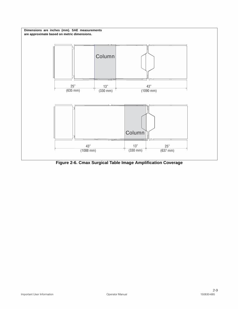
Figure 2-6. Cmax Surgical Table Image Amplification Coverage
25”(635mm)
13”(330mm)
43”(1090mm)
43”(1088mm)
13”(330mm)
25”(637mm)
Column
Column
25”(635 mm)
13”(330 mm)
43”(1090 mm)
43”(1088 mm)
13”(330 mm)
25”(637 mm)
Dimensions are inches (mm). SAE measurementsare approximate based on metric dimensions.
3-1Installation Instaructions Operator Manual 150830-685
Check the overall condition of the Cmax™ Surgical Table and anyapplicable accessories upon receipt to ensure nothing wasdamaged during shipment. If damage appears to have occurred,contact the shipping company and STERIS.
STERIS recommends that only STERIS-trained or STERIS-supervisedpersonnel attempt to uncrate/crate, install and perform maintenanceon the Cmax Surgical Table. Uncrating, crating, installation ormaintenance by others may result in personal injury or damage to theproduct. Any alteration of this equipment not authorized or performedby STERIS will void the warranty, could adversely affect proper tablefunctioning, could violate national, state and local regulations.
NOTE: A patient grounding post/potential equalization terminal (maleconnector, DIN 42801) is provided. The mating female connector forpatient grounding is not furnished by STERIS.
IMPORTANT: Before connecting the table to your ac power system,ensure table is marked for your power system (100, 120, 220 or 230/240).
Install the table as follows:
1. Position table at desired location.
NOTE: The power cord is approximately 20 ft (6 m) long. Ensuretable is positioned properly.
2. The Cmax table is equipped with INTELLIPOWER® dual power system modes. If table is to be operated on battery power, proceed to Step 8.
3. If not already installed, install battery fuse into table base as follows (see Figure 3-1):a. Locate correct battery fuse.
b. Unscrew and remove black fuse cap.
c. Insert fuse in cap.
d. Insert fuse (with cap) into fuse holder assembly in table base.e. Push in fuse and cap and turn a quarter turn to lock assembly
into table base. Pull on cap to ensure fuse is seated and locked properly.
NOTE: If table is going to be stored for more than six months,remove fuse to limit battery discharge.
4. Plug power cord into appropriate socket on table base (see Figure 3-2).
5. Plug power cord into appropriate facility outlet.
WARNING – PERSONAL INJURY HAZARD: • Keep hands and feet clear
of the unloading platform and the table base when unloading the table. Serious personal injury could result.
• If the integrity of the external protective ground installation or arrangement is in doubt, operate the table from its internal power source.
WARNING – EXPLOSION HAZARD: Table must not be used in the presence of flammable anesthetics.
WARNING – TRIPPING HAZARD: Route the power cord to the receptacle to minimize being tripped over by personnel in the area.
WARNING – PERSONAL INJURY AND/OR EQUIPMENT DAMAGE HAZARD: Table is factory set to operate at a certain voltage. Use of any other power supply could result in serious personal injury or table damage.
CAUTION – POSSIBLEEQUIPMENT DAMAGE: Whenmoving the table to or frompoint of use, roll it carefully atmoderate speed and only oversmooth floors. Maximum floorclearance is 1/4" (6.4 mm).Avoid door and elevator jambs,and obstructions greater than 1/4" (6.4 mm). If necessary, lifttable over obstructions, ontotrucks, etc. Lift table evenly andonly by the table base. DO NOTtransport articles (includingaccessories) on top of the table,and DO NOT use a forklift tomove the uncrated table.
If an antistatic path is necessary, STERIS recommendsantistatic pads (specifically developed for this table) indirect contact with the patient. Table must also bepositioned on antistatic floor or connected to equalizationdevice (equipotential connector).
INSTALLATION INSTRUCTIONS 3

3-2150830-685 Operator Manual Installation Instaructions
NOTE: Where the integrity of the external protective earth conductorarrangement is in doubt, use battery power only.
6. Turn Main Power Switch to ON. Switch turns Green and plug symbol on INTELLIPOWER® LED Display lights.
NOTE: A green Main Power Switch indicates facility power is availableto the Cmax table. A lighted plug symbol on the LED Display indicatesthe batteries are charging. Refer to SECTION 5.5, BATTERY CHARGING
PROCEDURE.
7. Route power cord to eliminate Tripping Hazard for facility personnel.
8. Remove hand control from package and plug into appropriate socket on table column (see Figure 3-3 and Figure 3-4) as follows:
a. Lift appropriate protective cover on connection panel.
b. Align red mark (or arrow) on hand control plug with red mark on table socket.
c. Push hand control plug into table socket until a "click" is heard.
d. Place hand control on table side rail.
9. Remove foot control (optional) from package and plug into appropriate socket on table column (see Figure 3-4 and Figure 3-5) as follows:
NOTE: The optional foot control allows operator to control HEIGHT,TREND and TILT movements.
a. Lift appropriate protective cover on connection panel.
Figure 3-1. Install/Remove Battery Fuse
C-M
AX
05
Ensure caps cover
sockets when not in use.
SERVE

3-3Installation Instaructions Operator Manual 150830-685
b. Align red mark (or arrow) on foot control plug with red mark on table socket.
c. Push foot control plug into table socket until a "click" is heard.
d. Place foot control where it will not be damaged.
10. Lock table by using hand control to activate floor locks.
11. Install head section as follows:
a. Fully loosen both locking thumbscrews located at bottom edge of back frame (see Figure 3-6).
b. Insert both head section installation rods into back frame until fully engaged.
NOTE: The head section should slide easily into back frame. Do notforce.
c. Fully tighten both locking thumbscrews to lock head section in place.
d. Pull head section (both sides) to ensure correct installation.
Figure 3-2. Connect Cmax Surgical Table to Facility Power
C-M
AX
04
CHARGE
BATTERY
INTELLI POWER
OFF
ON
Ensure caps cover
sockets when not in use.
SERVE
0 I0 I
3
Head End Foot End
3-4150830-685 Operator Manual Installation Instaructions
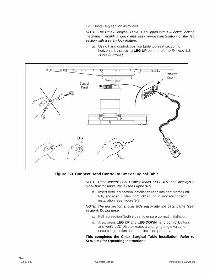
12. Install leg section as follows:
NOTE: The Cmax Surgical Table is equipped with Hi-Lock™ lockingmechanism enabling quick and easy removal/installation of the legsection with a safety lock feature.
a. Using hand control, position table top seat section to horizontal by pressing LEG UP button (refer to SECTION 4.2, HAND CONTROL).
NOTE: Hand control LCD Display reads LEG OUT and displays ablank box for Angle Value (see Figure 3-7).
b. Insert both leg section installation rods into seat frame until fully engaged. Listen for "click" sound to indicate correct installation (see Figure 3-8).
NOTE: The leg section should slide easily into the back frame (seatsection). Do not force.
c. Pull leg section (both sides) to ensure correct installation.
d. Also, press LEG UP and LEG DOWN hand control buttons and verify LCD Display reads a changing angle value to ensure leg section has been installed properly.
This completes the Cmax Surgical Table installation. Refer toSECTION 4 for Operating Instructions.
Figure 3-3. Connect Hand Control to Cmax Surgical Table
ControlPanel
Protective Cover
Click

3-5Installation Instaructions Operator Manual 150830-685
Figure 3-4. Connect Panel
Ensure caps cover
sockets when not in use.
SERVE
Figure 3-5. Connect Optional Foot Control to Cmax Surgical Table
C-M
AX
04
Ensure caps cover
sockets when not in use.
SERVE
Ensurecaps cover
sockets when not in use.
SERVE
Protective Cover
Control Panel
Connect Foot Control Disconnect Foot Control

3-6150830-685 Operator Manual Installation Instaructions
Figure 3-6. Install Head Section
Figure 3-7. Hand Control LCD Display
No Angle Value

3-7Installation Instaructions Operator Manual 150830-685
WARNING – PERSONAL INJURY HAZARD: The table leg section is designed to support the patient legs. Do not put body weight on the leg section.
Figure 3-8. Attaching Leg Section
«Click»

4-1Operating Instructions Operator Manual 150830-685
4.1 Operating Table Operate the Cmax™ Surgical Table as follows:
1. Review Pinch Point Warnings as presented in SECTION 2, PINCH POINT WARNINGS of this manual.
2. Cmax Surgical Table is equipped with Intellipower® dual power system. If table is to be operated on battery power, proceed to Step 4.
NOTE: For more information on the battery system, refer to SECTION
5.5, BATTERY CHARGING PROCEDURE.
3. Verify power cord is plugged into both the facility outlet and table receptacle and Main Power Switch is in ON position (lighted green).
4. For optimum performance, before attempting to operate table, allow table to reach room temperature (see Figure 4-1).
5. After referencing SECTION 4.2.1, HAND CONTROL FUNCTION BUTTONS DESCRIPTION, position tabletop to LEVEL.
NOTE: If the Hand Control AND Foot Control are installed, HandControl has priority. Also, the Cmax Table Head Section is manuallyadjusted as follows (if Head Section is not installed, refer to SECTION 3,INSTALLATION INSTRUCTIONS, Step 11):
1) The head section may be positioned UP and DOWN 90°from horizontal (level).
2) While holding head section securely in one hand, pullrelease handle (spring loaded) located under right side ofhead section (see Figure 4-2) and tilt head section todesired angle (level in this case).
3) Release handle to lock head section at desired angle. Moveheadrest slightly until ratchet mechanism locks headrest inposition.
WARNING – PERSONAL INJURY HAZARD:
• Section 4.1, Steps 1 - 6 in "Operating the Table" must be executed before patient transfer to the table. Execution of Steps 1 - 6 with the patient on the table could result in injury to both the patient and the operating room staff.
• Healthcare professionals must ensure that patients are positioned and monitored so as to prevent compromising respiration, nerve pathways, or circulation.
• Unanticipated table movement could cause patient injury. Patient must be secured to the table in accordance with recommended positioning practices.
• If the integrity of the external protective earth conductor installation or arrangement is in doubt, operate the table from its internal power source.
WARNING – PERSONAL INJURY AND/OR EQUIPMENT DAMAGE HAZARD:
• Table is factory set to operate at a certain voltage. Use of any other power supply could result in serious personal injury or table damage.
• Use of this table in the presence of flammable anesthetics could result in serious personal injury or table damage.
Figure 4-1. Cmax Surgical Table
OPERATING INSTRUCTIONS 4

4-2150830-685 Operator Manual Operating Instructions
6. Engage floor locks by pressing hand control LOCK button (see SECTION 4.2.1).
7. Before placing patient on table, ensure patient does not exceed maximum patient weight limit (patient in normal orientation) of 1100 lb (499 kg) without patient posturing or tabletop slide (except raise/lower); 1000 lb (454 kg) full patient posturing (except tabletop slide);600 lb (272 kg) full patient posturing (including tabletop slide). Assuming patient weight does not exceed table weight capacity, transfer or position patient and ensure patient is properly restrained (refer to SECTION 2.3, PATIENT SAFETY STRAPS, in this manual).
NOTE: A patient grounding post/potential equalization terminal (maleconnector, DIN 42801) is provided. The mating female connector forpatient grounding is not furnished by STERIS.
WARNING – PERSONAL INJURY AND/OR EQUIPMENT DAMAGE HAZARD: Placing a patient whose weight exceeds maximum patient weight limit (patient in normal orientation) of 1100 lb (499 kg) without patient posturing or tabletop slide (except raise/lower), 1000 lb (454 kg) with patient posturing (except tabletop slide), or 600 lb (272 kg) with full patient posturing (including tabletop slide) could result in injury to the patient and the operating room staff, and serious equipment damage.
WARNING – TIPPING HAZARD:
• Do not place patient on the table unless floor locks are engaged.
• Do not use this table for patients exceeding the maximum patient weight (patient in normal orientation) of 1100 lb (499 kg) without patient posturing or tabletop slide (except raise / lower), 1000 lb (454 kg) with patient posturing (except tabletop slide), or 600 lb (272 kg) with full patient posturing (including tabletop slide).
• Center tabletop over column before applying chest compressions.
WARNING – PERSONAL INJURY HAZARD: The Table Leg Section is designed to support the patient legs. Do not put body weight on the Leg Section.
Figure 4-2. Head Section Operation (Typical)
Handle
90°
90°
4-3Operating Instructions Operator Manual 150830-685
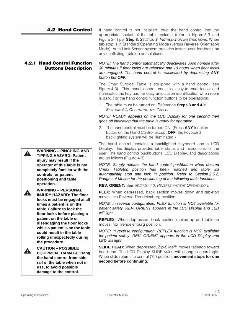
4.2 Hand Control If hand control is not installed, plug the hand control into theappropriate socket of the table column (refer to Figure 3-3 andFigure 3-4) per Step 8, SECTION 3, INSTALLATION INSTRUCTIONS. Whentabletop is in Standard Operating Mode (versus Reverse OrientationMode), Auto Limit Sensor system provides instant user feedback onany conflicting tabletop articulations.
4.2.1 Hand Control FunctionButtons Description
NOTE: The hand control automatically deactivates upon nonuse after30 minutes if floor locks are released and 10 hours when floor locksare engaged. The hand control is reactivated by depressing ANYbutton but OFF.
The Cmax Surgical Table is equipped with a hand control (seeFigure 4-3). This hand control contains easy-to-read icons andilluminates the key pad for easy articulation identification when roomis dark. For the hand control function buttons to be operational:
1. The table must be turned on. Reference Steps 3 and 4 in SECTION 4.1, OPERATING THE TABLE.
NOTE: READY appears on the LCD Display for one second thengoes off indicating that the table is ready for operation.
2. The hand control must be turned ON. (Press ANY function button on the Hand Control except OFF; the keyboard backlighting system will be illuminated.)
The hand control contains a backlighted keyboard and a LCDDisplay. This display provides table status and instructions for theuser. The hand control pushbuttons, LCD Display, and descriptionsare as follows (Figure 4-3):
NOTE: Simply release the hand control pushbutton when desiredCmax Tabletop position has been reached and table willautomatically stop and lock in position. Refer to Section 2.5.2,Ranges of Motion for the positioning of the following table functions.
REV. ORIENT: See SECTION 4.3, REVERSE PATIENT ORIENTATION.
FLEX: When depressed, back section moves down and tabletopmoves into Reverse Trendelenburg position.
NOTE: In reverse configuration, FLEX function is NOT available forpatient safety. REV. ORIENT appears in the LCD Display and LEDwill light.
REFLEX: When depressed, back section moves up and tabletopmoves into Trendelenburg position.
NOTE: In reverse configuration, REFLEX function is NOT availablefor patient safety. REV. ORIENT appears in the LCD Display andLED will light.
SLIDE HEAD: When depressed, Zip-Slide™ moves tabletop towardhead end. The LCD Display SLIDE value will change accordingly.When slide returns to central ("0") position, movement stops for onesecond before continuing.
WARNING – PINCHING AND TIPPING HAZARD: Patient injury may result if the operator of this table is not completely familiar with the controls for patient positioning and table operation.
WARNING – PERSONAL INJURY HAZARD: The floor locks must be engaged at all times a patient is on the table. Failure to lock the floor locks before placing a patient on the table or disengaging the floor locks while a patient is on the table could result in the table rolling unexpectedly during the procedure.
CAUTION – POSSIBLE EQUIPMENT DAMAGE: Hang the hand control from side rail of the table when not in use, to avoid possible damage to the control.

4-4150830-685 Operator Manual Operating Instructions
SLIDE FOOT: When depressed, Zip-Slide moves tabletop towardfoot end. The LCD Display SLIDE value will change accordingly.When slide returns to central ("0") position, movement stops for onesecond before continuing.
HEIGHT UP: When depressed, the entire tabletop will rise. The LCDDisplay HEIGHT value will change accordingly.
HEIGHT DOWN: When depressed, the entire tabletop will lower.The LCD Display HEIGHT value will change accordingly.
Figure 4-3. Cmax Surgical Table Hand Control

4-5Operating Instructions Operator Manual 150830-685
TREND: When depressed, the head end of the tabletop will lower;or, foot end will raise. The LCD Display TREND value will changeaccordingly.
REV. TREND: When depressed, the head end of the tabletop willrise; or, foot end will lower. The LCD Display TREND value willchange accordingly.
TILT LEFT: When depressed, the tabletop will roll to the left(patient's left or viewing the table from the head end). The LCDDisplay LATERAL TILT value will change accordingly.
TILT RIGHT: When depressed, the tabletop will roll to the right(patient's right or viewing the table from the head end). The LCDDisplay LATERAL TILT value will change accordingly.
BACK UP: When depressed, the tabletop back section will raise.The LCD Display BACK SECTION value will change accordingly.
BACK DOWN: When depressed, the tabletop back section willlower. The LCD Display BACK SECTION value will changeaccordingly.
LEG UP: When depressed, the tabletop leg section will raise. TheLCD Display LEG SECTION value will change accordingly.
LEG DOWN: When depressed, the tabletop leg section will lower.The LCD Display LEG SECTION value will change accordingly.
KIDNEY UP: When depressed, the tabletop Kidney™ ElevatorMechanism will raise up to the maximum 4" (110 mm). The LCDDisplay kidney T symbol will come ON accordingly.
KIDNEY DOWN: When depressed, the tabletop Kidney ElevatorMechanism will lower. The LCD Display kidney T symbol will go OFFaccordingly.
LEVEL: When depressed, the tabletop is gradually returned to levelor horizontal position by aligning the tabletop sections in thefollowing order:
• Kidney Elevator Mechanism and lateral tilt;
• Trendelenburg and back;
• Leg.
The LCD Display values will change accordingly.
NOTE: When operating in REVERSE ORIENTATION, LEVELfunction does NOT operate.
FLOOR LOCK, LOCK, UNLOCK: When FLOOR LOCK button isdepressed, the LCD Display will show the symbols for LOCK orUNLOCK. Press LOCK and the control system will order the floorlocks to lower. While the floor locks are lowering, the LCD Display willshow LOCKING. Once the floor locks are engaged, the Lock Symbolwill come ON. If Slide is not centered at 0” the message SLIDEHEADor SLIDEFOOT is displayed and floor locks will not release. PositionSlide to 0” for floor lock release.

4-6150830-685 Operator Manual Operating Instructions
NOTE: When table is in the UNLOCK configuration, NO tabletopfunctioning is active. If a tabletop function button is pressed whiletable is in the UNLOCK configuration, the LCD Display will showLOCK TABLE.
OFF: When depressed, all hand control function buttons deactivate.All functions are stopped immediately.
NOTE: The hand control automatically deactivates upon nonuse after30 minutes if floor locks are released and 10 hours when floor locksare engaged. The hand control is reactivated by depressing ANYbutton but OFF.
4.2.2 Hand Control LCDDisplay Description
The Hand Control is equipped with a LCD (Liquid Crystal Display)Display to assist in the table operation (see Figure 4-4). The LCDDisplay indicator descriptions are as follows:
NOTE: Numbers in ( ) refer to items shown in Figure 4-4
LCD Display (1): displays any control system messages to the userabout table operation.
LCD Status Indicators (2): indicates the table is receiving powerfrom the table batteries (battery icon) or facility power (plug icon)and whether the table floor locks are engaged or not (lock or openlock icons). This also may indicate an operational situation, seeMaintenance (11). Refer to Section 6, Troubleshooting, for moreinformation.
Height Level (3): indicates the tabletop height from 0 to 19" (0 to 483 mm).
NOTE: Height Level and Slide Valueindications can be switched from inchesto centimeters (or centimeters to inches)by simultaneously pressing LEVEL andFLEX pushbuttons just after (within fiveseconds) of turning table ON.
Trendelenburg/Reverse Trendelenburg Angle (4): indicates thetabletop angle of Trendelenburg (upward pointing arrow) or ReverseTrendelenburg (downward pointing arrow) from 0 to 30°.
Lateral Tilt Angle (5): indicates the tabletop angle of right lateral tilt(upward pointing arrow) or left lateral tilt (downward pointing arrow)from 0 to 20°.
Back Section Angle (6): indicates the tabletop back section anglemovement in relation to the level seat section. Up (upward pointingarrow) from 0 to 90° or down (downward pointing arrow) from 0 to40°.
Leg Section Angle (7): indicates the tabletop leg section movementin relation to the level seat section. Up (upward pointing arrow) ordown (downward pointing arrow) from 0 to 105°.
Slide Value (8): indicates the tabletop slide or horizontal movementin relation to centered position. Head slide value (left arrow) and footslide value (right arrow) from 0 to 9" (0 to 229 mm).

4-7Operating Instructions Operator Manual 150830-685
KIDNEY Elevator Mechanism (9): when T symbol is ON, KidneyElevator Mechanism is UP; no T symbol, KIDNEY Elevator is at levelposition.
Auto Limit Sensors (ALS) Warning (10): indicates the tabletop hasbeen ordered into a configuration or has moved into a position thatmay cause tabletop damage or patient injury. This feedback is fromthe Auto Limit Sensor™ (patent pending) control device system. Toprevent a tabletop sectional conflict, or collision of tabletop with thetable or floor, ALS System immediately stops the movement inprocess and the ALS LED lights. The control system will alert theuser to an alternative movement choice in the LCD Display (1).
NOTE: The ALS System suggested alternative movement is not theonly movement available.
Maintenance Key (11): when Y symbol is ON, the auto-diagnosticsystem has detected a situation. Check the LCD Display (1) for moreinformation on the nature of the situation. Press OFF key and thenstart the hand control again to see if the situation disappears. If not,refer to SECTION 6, TROUBLESHOOTING for more information.
NOTE: The LCD Display values are approximate. Their accuracy mayvary according to environmental conditions (e.g., altitude, humidity,temperature). Also, if a sensor is not operating properly, the valueindicated will be incorrect. Ensure checking patient positioningvisually before proceeding.
WARNING – PERSONAL INJURY AND/OR EQUIPMENT DAMAGE HAZARD: The Auto Limit Sensor (ALS) System suggested alternative tabletop movement does not take in account the type of surgery that may be in process or the environment (e.g., other equipment close by) and might not be compatible with the surgical procedure. To avoid an action that could result in death or serious injury to the patient and the operating room staff, and/or serious equipment damage, completely evaluate the feasibility of the suggestion.

4-8150830-685 Operator Manual Operating Instructions
Figure 4-4. Hand Control LCD Display
C-M
AX
08aa
03"
00"
20° T
00°
TREND TILT
00°
SLIDE HEAD !
04°
03"
00"20¡
T
00¡
TREND
TILT
00¡
SLIDE HEAD
!
-04¡
6 9 8 2
3
4 1 5
7AUTO
LIM
IT
SENSORS
10
inches/46cm)rg angle value
1 1
KEY:
1. LCD Display2. LCD Status Indicators3. Height Level4. Trendelenburg/Reverse Trendelenburg Angle5. Lateral Tilt Angle6. Back Section Angle7. Leg Section Angle8. Slide Value9. Kidney Elevator Mechanism10. ALS Warning11. Maintenance Key
4-9Operating Instructions Operator Manual 150830-685
4.3 Reverse PatientOrientation
Some surgeries (e.g., shoulder) require the patient to be in reversepositioning and the table to be operated in a reverse configuration.Press REV. ORIENT button on hand control (see Figure 4-3), LEDshould light. Press REV. ORIENT button again to cancel ReverseOrientation function.
When REV. ORIENT button is pressed, all other hand controlcommands (through the control system) note the new patient headposition. Trendelenburg and Lateral Tilt movements and Back andLeg Sections are automatically reversed.
IMPORTANT:When using the REV. ORIENT button, note thefollowing:
1) The information displayed on the LCD is NOT reversed.
2) When table is turned OFF, control system stores orientationstatus. Before any new positioning is attempted, ensure tablepatient configuration is correct.
3) The Cmax Table Head Section is manually adjusted and willnot be affected by REV. ORIENT button operation.
4) FLEX and REFLEX functions are NOT available for patientsafety.
5) When operating in REVERSE ORIENTATION, LEVEL functiondoes NOT operate.
6) The hand control automatically deactivates after two minutes ofnonuse. The hand control is reactivated by depressing ANYbutton but OFF.
4.4 Optional FootControl Operation
The Cmax Surgical Table may be operated using the optional footcontrol as follows:
1. Connect foot control cord to appropriate control panel socket on table column (refer to Figure 3-5).
2. The foot control allows operator to control HEIGHT, TREND, and TILT movements.
3. Press and release any positioning pedal to switch table control ON. If the hand control is also attached, PEDAL ON will appear on the LCD Display message window.
NOTE: When using the hand control and optional foot control at thesame time, the hand control has priority. Also, if the hand control OFFbutton is pressed, foot control will also switch OFF.
4. If foot control is unplugged from table, ENSURE protective cover is placed over opening.
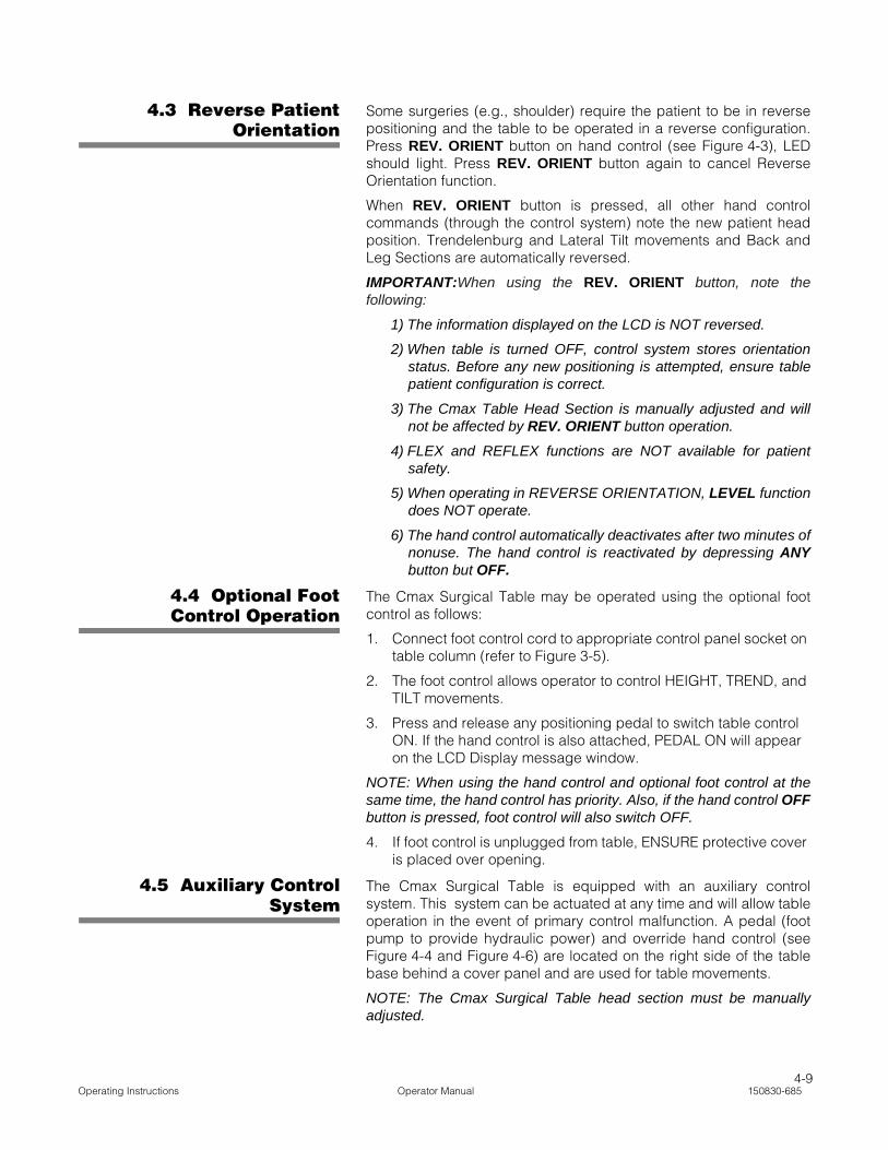
4.5 Auxiliary ControlSystem
The Cmax Surgical Table is equipped with an auxiliary controlsystem. This system can be actuated at any time and will allow tableoperation in the event of primary control malfunction. A pedal (footpump to provide hydraulic power) and override hand control (seeFigure 4-4 and Figure 4-6) are located on the right side of the tablebase behind a cover panel and are used for table movements.
NOTE: The Cmax Surgical Table head section must be manuallyadjusted.
4-10150830-685 Operator Manual Operating Instructions
4.5.1 Auxiliary SystemOperation
To operate system, proceed as follows:
1. Flip pedal down (see Figure 4-5).
2. Pull drawer out and remove auxiliary hand control.
3. Return drawer to table.
4. To operate table functions, pump pedal while pressing desired function button on auxiliary hand control (see Figure 4-6).
NOTE: When using the auxiliary control system, note the following:
1) For UNLOCK and SLIDE functions, it is not necessary to pumppedal.
2) Pressing any button on the auxiliary hand control deactivatesmain hand control.
3) When any key is pressed on auxiliary hand control, the greenLED (see Figure 4-6) should light indicating system is active.
4) The ALS System is NOT active during auxiliary controloperation.
5) When table is in the auxiliary UNLOCK configuration, tabletopfunctioning IS active. LOCK table before moving tabletop.
6) Reverse Orientation is NOT available in auxiliary controloperation. If patient was in reverse orientation when auxiliarycontrol was activated, change TREND to REV. TREND, LEFTTILT to RIGHT TILT, etc.
WARNING – PERSONAL INJURY AND/OR EQUIPMENT DAMAGE HAZARD:
• ALS System is not active during Auxiliary Control. Ensure proper tabletop movements to prevent patient/staff injury and/or equipment damage.
• During Auxiliary Control, tabletop functions are available even if table floor locks are NOT engaged. LOCK table before moving tabletop or transferring patient.
Figure 4-5. Auxiliary Control System

4-11Operating Instructions Operator Manual 150830-685
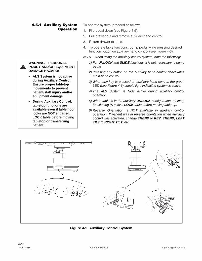
4.5.2 Auxiliary Hand ControlDescription
The auxiliary hand control pushbutton descriptions are as follows(Figure 4-6):
NOTE: Simply release the auxiliary hand control pushbutton whendesired Cmax Tabletop position has been reached and table willautomatically stop and lock in position. Refer to SECTION 2.5.2,RANGES OF MOTION, for the positioning of the following tablefunctions.
SLIDE HEAD: When depressed, Zip-Slide moves tabletop towardhead end. When slide returns to central ("0") position, movementstops for one second before continuing.
SLIDE FOOT: When depressed, Zip-Slide moves tabletop towardfoot end. When slide returns to central ("0") position, movement stopsfor one second before continuing.
HEIGHT UP: When depressed and pumping simultaneously, theentire tabletop will rise.
HEIGHT DOWN: When depressed and pumping simultaneously, theentire tabletop will lower.
TREND: When depressed and pumping simultaneously, the headend of the tabletop will lower; or, foot end will raise.
REV. TREND: When depressed and pumping simultaneously, thehead end of the tabletop will rise; or, foot end will lower.
TILT LEFT: When depressed and pumping simultaneously, thetabletop will roll to the left (patient's left or viewing the table from thehead end).
TILT RIGHT: When depressed and pumping simultaneously, thetabletop will roll to the right (patient's right or viewing the table fromthe head end).
BACK UP: When depressed and pumping simultaneously, thetabletop back section will raise.
BACK DOWN: When depressed and pumping simultaneously, thetabletop back section will lower.
LEG UP: When depressed and pumping simultaneously, thetabletop leg section will raise.
LEG DOWN: When depressed and pumping simultaneously, thetabletop leg section will lower.
KIDNEY UP: When depressed and pumping simultaneously, thetabletop KIDNEY Elevator will raise up to the maximum 4" (110 mm).
KIDNEY DOWN: When depressed and pumping, the tabletopKidney Elevator Mechanism will lower.
LOCK: When depressed and pumping simultaneously, floor locksare slowly lowered. To ensure table is correctly secured to the floor,gently push on table.
UNLOCK: When depressed, floor locks are slowly released. Toensure floor locks are completely disengaged, gently push on table.
NOTE: When table is in the auxiliary UNLOCK configuration, tabletopfunctioning IS active. LOCK table before moving tabletop.
4-12150830-685 Operator Manual Operating Instructions
4.5.3 Return Auxiliary ControlSystem
When situation has been corrected and normal table operation isavailable, replace auxiliary control system as follows (seeSection Figure 4-5):
1. Pull drawer out from right side of table base.
2. Place auxiliary hand control face down in right side of drawer.
3. Wind cable and place in left side of drawer.
4. Push drawer back into table base.
NOTE: When returning drawer to table base, ensure cable is notjammed.
5. Fold pedal back to original position.
4.6 Leg SectionRemoval
The Cmax Surgical Table leg section is designed to be easilyremoved (Hi-Lock™ locking mechanism) to enable proceduresrequiring optional leg supports. Remove the leg section as follows:
Figure 4-6. Auxiliary Hand Control
Pump LineGreen LED
4-13Operating Instructions Operator Manual 150830-685
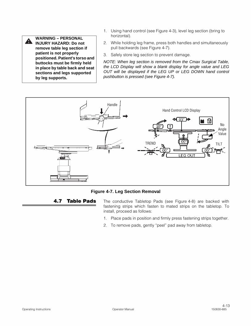
1. Using hand control (see Figure 4-3), level leg section (bring to horizontal).
2. While holding leg frame, press both handles and simultaneously pull backwards (see Figure 4-7).
3. Safely store leg section to prevent damage.
NOTE: When leg section is removed from the Cmax Surgical Table,the LCD Display will show a blank display for angle value and LEGOUT will be displayed if the LEG UP or LEG DOWN hand controlpushbutton is pressed (see Figure 4-7).
4.7 Table Pads The conductive Tabletop Pads (see Figure 4-8) are backed withfastening strips which fasten to mated strips on the tabletop. Toinstall, proceed as follows:
1. Place pads in position and firmly press fastening strips together.
2. To remove pads, gently “peel” pad away from tabletop.
WARNING – PERSONAL INJURY HAZARD: Do not remove table leg section if patient is not properly positioned. Patient's torso and buttocks must be firmly held in place by table back and seat sections and legs supported by leg supports.
Figure 4-7. Leg Section Removal
HandleHand Control LCD Display
No Angle Value
TREND TILT

4-14150830-685 Operator Manual Operating Instructions
4.8 X-Ray TopInstallation
The Cmax Surgical Table is designed to enable installation of an X-ray top to allow use of X-ray cassette film. Attach the four-part X-raytop as follows (see Figure 4-9):
1. Carefully remove X-ray top sections from packing container.
2. Remove pads from tabletop (see SECTION 4.7).
3. Position X-ray top section over corresponding tabletop section, aligning posts to mounting holes.
4. Press down on X-ray top section until a "click" is heard.
5. Ensure X-ray top sections are securely mounted by gently pulling up on section.
6. Reinstall tabletop pads.
7. Remove and store X-ray top by reversing above steps.
Figure 4-8. Tabletop Pads

4-15Operating Instructions Operator Manual 150830-685
4.9 Accessories/SideRails
The standard STERIS permanently attached 3/8" wide x 1-1/8" tallside rails allow for the use of many standard surgery tableattachments and accessories. The rails consist of one rail mountedto each side of each tabletop main section.
For complete information on accessory options, consult STERIS.
Figure 4-9. X-Ray Top Installation
Ensure caps cover
sockets when not in use.
SERVE
C-M
AX
10
2
1
CLICK
LLING X-RAY TOP
pds and stow it with care.
4-16150830-685 Operator Manual Operating Instructions
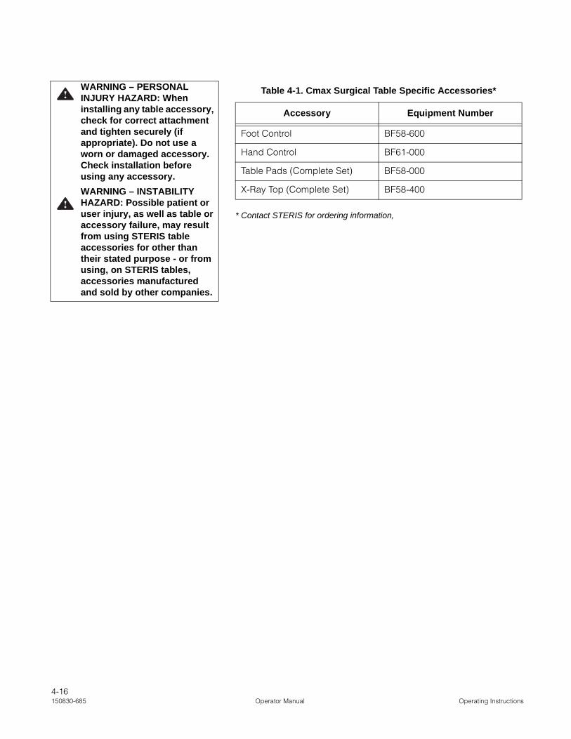
* Contact STERIS for ordering information,
WARNING – PERSONAL INJURY HAZARD: When installing any table accessory, check for correct attachment and tighten securely (if appropriate). Do not use a worn or damaged accessory. Check installation before using any accessory.
WARNING – INSTABILITY HAZARD: Possible patient or user injury, as well as table or accessory failure, may result from using STERIS table accessories for other than their stated purpose - or from using, on STERIS tables, accessories manufactured and sold by other companies.
Table 4-1. Cmax Surgical Table Specific Accessories*
Accessory Equipment Number
Foot Control BF58-600
Hand Control BF61-000
Table Pads (Complete Set) BF58-000
X-Ray Top (Complete Set) BF58-400

5-1Routine Maintenance Operator Manual 150830-685
5.1 Read BeforePerforming Routine
Maintenance
The routine maintenance procedures described in this section of themanual should be performed whenever necessary and as outlined inTABLE 5-2, PREVENTIVE MAINTENANCE SCHEDULE. Any maintenanceprocedures not included in this section should be performed only bySTERIS-trained service personnel fully acquainted with the Cmax™
Surgical Table.
In addition to the routine maintenance described in this section, reg-ularly scheduled preventive maintenance is essential for safe andreliable operation of the equipment. Annual maintenance programsare available to provide scheduled maintenance, adjustments andreplacement of worn parts performed by a qualified technician, tohelp ensure peak equipment performance and help avoidunscheduled downtime. Contact STERIS for details.
Maintain a record of all maintenance procedures performed on thisCmax Surgical Table. If a problem occurs, refer to SECTION 6,TROUBLESHOOTING, or contact STERIS.
NOTE: Never permit unqualified persons to service this equipment.
WARNING – PERSONAL INJURY AND/OR EQUIPMENT DAMAGE HAZARD:
• Repairs and adjustments to this equipment must be made only by STERIS or STERIS-trained service personnel. Maintenance performed by unqualified personnel or installation of unauthorized parts could cause personal injury, result in improper equipment performance, invalidate the warranty, or result in costly damage. Contact STERIS regarding service options.
• Regularly scheduled preventive maintenance is required for safe and reliable operation of this equipment. Contact STERIS to schedule preventive maintenance.
ROUTINE MAINTENANCE 5

5-2150830-685 Operator Manual Routine Maintenance
5.2 Cleaning Table NOTE: The user must follow the requirements of the nationalcommittee responsible for hygiene and disinfection when cleaningtable.
See Table 5-1 for recommended cleaning products. Clean the entiretable per the following procedures.
* Contact STERIS for ordering information.
5.2.1 General Use the following materials to perform the cleaning proceduresdescribed in this section:
• Several clean, dry lint-free cloths.
• Container of clean water.
• Cleaning products listed in Table 5-1, RECOMMENDED CLEANING
PRODUCTS.
NOTE: When using disinfectants, follow all manufacturer's labelrecommendations.
WARNING – INFECTION HAZARD:
• To protect against aerosols being reflected from potentially contaminated surfaces, wear rubber or plastic gloves, masks and eye protection, and follow OSHA blood-borne pathogens standards when cleaning.
• When cleaning/disinfecting table, do not use alcohol which does not have sufficient cleaning/disinfection properties.
WARNING –PERSONAL INJURY HAZARD: When cleaning/disinfecting table, do not use phenolics, which may cause patient skin burns if inadequately rinsed off, or alcohol, which does not have sufficient cleaning/disinfection properties.
Table 5-1. Recommended Cleaning Products*
Product Name Product Use
Coverage® Spray HB Plus Ready-to-Use One-Step
Disinfectant Cleaner
Hospital-grade quaternary-based disinfectant spray
Coverage® HB Concentrated Disinfectant Cleaner
EPA-registered Hepatitis-B-effective quaternary
T.B.Q® Hard Surface Disinfectant
Detergent-based germicide
Germicidal Surface Wipes Disinfecting/Deoderizing/
Cleaning Wipes
Surface disinfectant

5-3Routine Maintenance Operator Manual 150830-685
5.2.2 After Each Usage After each use of the Cmax Surgical Table, clean/disinfect asfollows:
NOTE: Ensure all protective covers are installed over any openreceptacles.
1. Remove gross soil with a disposable cloth and place used cloth in an appropriate biohazardous waste disposal container.
2. Clean tabletop and pads as follows:
a. Articulate tabletop to level and place at comfortable working height.
b. Gently "peel" pad away from tabletop fastening strips and place on another table or flat surface.
c. Hold can 6-8" (152-203 mm) from surface and spray cleaning fluid liberally on top and sides of pads. (It is recommended to clean only one pad at a time.) Carefully avoid any pad seams.
NOTE: Do not use any oxidizing products with chloric deriva-tive base such as bleach, or oxygenic derivatives such asperacetic acid.
d. Wipe sprayed surfaces with a clean lint-free cloth dampened with water to remove cleaning fluid (dampening cloth will minimize streaking).
e. Wipe cleaned surfaces again with clean, damp, lint-free cloth to remove residue.
f. Wipe cleaned surfaces again with clean, dry, lint-free cloth to remove all moisture.
g. Repeat Steps c, d, and e for other pads. Repeat Steps c, d, e, and f for tabletop surfaces exposed when pads are removed. Thoroughly dry bottom of pads and tabletop surfaces.
h. Place pads back onto tabletop by aligning with sides of table and pressing into place on fastening strips.
3. Raise table to maximum height to access lower surfaces.
4. Clean yoke, shrouds and entire base surface as follows:
a. Hold can 6-8" (152-203 mm) from surface and spray cleaning fluid liberally on yoke and shrouds. Avoid spraying in direction of connectors.
b. Wipe sprayed surfaces with a clean cloth dampened with water to remove cleaning fluid (dampening cloth will minimize streaking).
c. Wipe cleaned surfaces again with a clean, damp, lint-free cloth to remove residue.
d. Repeat Steps a, b, and c for base surface.
WARNING – INFECTION HAZARD: To protect against aerosols being reflected from potentially contaminated surfaces, wear rubber or plastic gloves, masks and eye protection, and follow OSHA blood-borne pathogens standards when cleaning.
WARNING –PERSONAL INJURY HAZARD: When cleaning/disinfecting table, do not use phenolics, which may cause patient skin burns if inadequately rinsed off, or alcohol, which does not have sufficient cleaning/disinfection properties.
CAUTION – POSSIBLE EQUIPMENT DAMAGE:
• When cleaning/disinfecting table, thoroughly read the cleaning fluid directions for use and follow all directions and cautions as shown.
• Cleaning procedures requiring articulation of the table should be performed only by persons familiar with table operation.
• Do not spray cleaning fluid into electric receptacles and avoid spraying directly on emergency backup buttons or into clearance space. Spray or drippage may settle onto electric circuits inside table causing corrosion and loss of function.
• After performing cleaning procedures, ensure pads, tabletop and x-ray tops are completely dry before reinstalling. Moisture trapped between pads and x-ray tops may contribute to equipment damage, such as x-ray top warpage.
5-4150830-685 Operator Manual Routine Maintenance
5. Turn hand control OFF and clean as follows:
NOTE: Do NOT immerse hand control in liquid.
a. Hold can 6-8" (152-203 mm) from surface and spray cleaning fluid liberally on hand control.
b. Wipe sprayed surfaces with a clean cloth dampened with water to remove cleaning fluid (dampening cloth will minimize streaking).
5.2.3 End-of-Day CleaningProcedure
At the end of each day, perform the cleaning procedures as outlinedin SECTION 5.2.2, AFTER EACH USAGE.
5.2.4 Weekly CleaningProcedure
After each weekly use of the Cmax Surgical Table, clean/disinfecttable as follows:
1. Perform Steps 1 through 4 of SECTION 5.2.2, AFTER EACH USAGE.
2. Check table casters and floor locks for any accumulated debris and clean as follows:
a. Ensure floor locks are properly engaged (raising casters off floor).
b. Hold cleaner spray can 6-8" (152-203 mm) from caster and spray cleaning fluid liberally on the caster.
c. Wipe caster with a cloth, dampened with water, to remove cleaning fluid and debris.
d. Perform Steps b and c for remaining three casters.
3. Articulate table through all movements and clean all additional surfaces exposed during these articulations as follows:
a. Hold spray cleaner can 6-8" (152-203 mm) from surface to be cleaned and spray cleaning fluid liberally on surface.
b. Wipe sprayed surfaces with a clean lint-free cloth, dampened with water to remove cleaning fluid.
c. Wipe cleaned surfaces again with a clean, damp, lint-free cloth to remove any remaining residue.
4. Turn hand control OFF when finished with cleaning procedure.
5. Perform Steps 5 and 6 of SECTION 5.2.2, AFTER EACH USAGE.
5.3 Bi-WeeklyMaintenance
Operate each Cmax Surgical Table function (refer to SECTION 4,OPERATING INSTRUCTIONS). Operation should be smooth and quiet. Iftable operation is not smooth, have a qualified technician repair thetable. Never permit inexperienced, unqualified persons to attempt tomake any repairs to the table.
5.4 MonthlyMaintenance
Check Cmax Surgical Table casters and floor locks for anyaccumulated debris and clean as follows:
1. Ensure floor locks are properly engaged.
2. Hold spray cleaner can 6-8" (152-203 mm) from caster and spray cleaning fluid liberally on the caster.
5-5150830-685 Operator Manual Routine Maintenance
3. Wipe caster with a cloth, dampened with water, to remove cleaning fluid and debris. Ensure items such as suture, oils, and floor wax are removed.
4. Perform Steps 2 and 3 for remaining three casters.
5.5 Battery ChargingProcedure
Cmax Surgical Table is equipped with INTELLIPOWER® dual powersystem. The table is powered either by facility power or by internalbatteries. If table is to be operated on battery power, note thefollowing:
IMPORTANT: Batteries are recharged automatically as long as theMain Power Switch is set to ON (lighted green) and the ac power isconnected to the Cmax Surgical Table. The PLUG icon appears onPower Panel LED Display (see Figure 5-1) indicating ac power anddiode bar indicates battery condition.
Bar graph description for 120 V tables:
• When table is plugged into facility ac and Main Power Switch isON, diode bar shows battery charge state. This battery chargestate is also indicated by icon on primary hand control (refer toFigure 4-4).
• When table is on battery power and primary hand control isactive (on), diode bar shows battery charge state. This batterycharge state is also indicated by icon on primary hand control(refer to Figure 4-4).
Bar graph description for 220 V tables:
• When table is plugged into facility ac and Main Power Switch isON, diode bar shows battery charge state. This battery chargestate is also indicated by icon on primary hand control (refer toFigure 4-4).
• When table is on battery power and primary hand control isactive (on), diode bar is off. Battery charge state is indicated byicon on primary hand control (refer to Figure 4-4).
Batteries will require recharging on a periodic basis depending onfrequency of table usage. Low or discharged battery conditions areindicated by HALF FILLED or EMPTY BATTERY icon on the HandControl (refer to Figure 4-4 and SECTION 4.2.2, HAND CONTROL LCDDISPLAY DESCRIPTION) and some or all green diode bars on PowerPanel LED Display are OFF.
NOTE: Fully charged batteries enable between 100 and 150procedures (approximately three weeks) without recharging. Note thecharge/discharge icon on the LED Display (see Figure 5-1) of PowerPanel.
Lead acid batteries last longer if not fully discharged. Therefore, toobtain the longest life and capacity from your Cmax Surgical Tablebatteries, always connect ac power cord to table base and plug intoan appropriate ac receptacle as often as possible, and as long aspossible, with the Main Power Switch set to ON (lighted green). If thisis not always possible, recharge batteries at the following times:
NOTE: When two green diode bars on Power Panel LED Display areOFF, batteries are half charged. This level of power enables normal
WARNING – PERSONAL INJURY AND/OR EQUIPMENT DAMAGE HAZARD: Repairs and adjustments to this equipment must be made only by STERIS or STERIS-trained service personnel. Maintenance performed by unqualified personnel or installation of unauthorized parts could cause personal injury, result in improper equipment performance, invalidate the warranty, or result in costly damage. Contact STERIS regarding service options.
WARNING – TRIPPING HAZARD: Route the power cord to the receptacle in a position so that it will not be tripped over by personnel in the area.
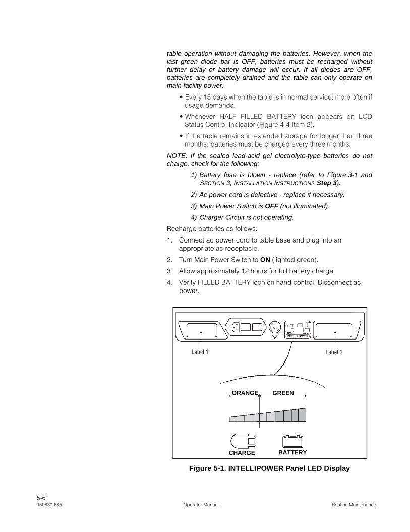
5-6150830-685 Operator Manual Routine Maintenance
table operation without damaging the batteries. However, when thelast green diode bar is OFF, batteries must be recharged withoutfurther delay or battery damage will occur. If all diodes are OFF,batteries are completely drained and the table can only operate onmain facility power.
• Every 15 days when the table is in normal service; more often ifusage demands.
• Whenever HALF FILLED BATTERY icon appears on LCDStatus Control Indicator (Figure 4-4 Item 2).
• If the table remains in extended storage for longer than threemonths; batteries must be charged every three months.
NOTE: If the sealed lead-acid gel electrolyte-type batteries do notcharge, check for the following:
1) Battery fuse is blown - replace (refer to Figure 3-1 andSECTION 3, INSTALLATION INSTRUCTIONS Step 3).
2) Ac power cord is defective - replace if necessary.
3) Main Power Switch is OFF (not illuminated).
4) Charger Circuit is not operating.
Recharge batteries as follows:
1. Connect ac power cord to table base and plug into an appropriate ac receptacle.
2. Turn Main Power Switch to ON (lighted green).
3. Allow approximately 12 hours for full battery charge.
4. Verify FILLED BATTERY icon on hand control. Disconnect ac power.
Figure 5-1. INTELLIPOWER Panel LED Display
Label 1 Label 2
ORANGE GREEN
CHARGE BATTERY

5-7Routine Maintenance Operator Manual 150830-685
5.6 PreventiveMaintenance Schedule
Maintenance procedures described in SECTION 5.2 through 5.5 mustbe performed regularly at the indicated intervals. Use the PreventiveMaintenance Schedule in Table 5-2 as a guide for further CmaxSurgical Table maintenance. Table usage may require more frequentmaintenance than indicated. See SECTION 5.7 for REPLACEMENT
PARTS.
Customer should maintain a record of all maintenance proceduresperformed on the table.
If a problem occurs, refer to SECTION 6, TROUBLESHOOTING.
NOTE: Never permit unqualified persons to service the table andPreventive Maintenance is not covered under warranty.
WARNING – PERSONAL INJURY AND/OR EQUIPMENT DAMAGE HAZARD: Failure to perform periodic inspections of the table could result in serious personal injury or equipment damage.
Table 5-2. Preventive Maintenance Schedule for Cmax Surgical Table
Service Required Minimum Frequency
1.0 PREPARATION FOR PREVENTIVE MAINTENANCE
Discuss equipment operation with department personnel. 1 x per year
Remove pads. Examine pad covers and fastening strips (pads and table). 1 x per year
Examine clamps and other side rail hardware. 1 x per year
Tighten side rails. 1 x per year
Unfasten and remove table shrouds and base cover. 1 x per year
Remove and inspect x-ray tops on each tabletop section (if equipped). 1 x per year
2.0 HYDRAULIC SYSTEM
Check hydraulic oil level. 1 x per year
Inspect floor directly beneath table and all hoses, fittings and components of hydraulic system for evidence of oil leaks.
1 x per year
Verify operation of Auxiliary Control System foot pedal. 1 x per year
3.0 CASTERS AND FLOOR LOCKS
Clean and inspect casters. 1 x per year
Lubricate casters. 1 x per year
Check floor-lock mechanism for proper operation. 1 x per year
4.0 CONTROLS
Using hand control or optional foot control, check table positioning. 1 x per year
5.0 ELECTRICAL CHECKS
Ensure all circuit board connectors and cable plugs are tight. 1 x per year
Check all cables for damage or fraying. 1 x per year
Inspect electrical cord and hand control cable. 1 x per year
Verify operation of Auxiliary Control System. 1 x per year

5-8150830-685 Operator Manual Routine Maintenance
5.7 Replacement Parts The parts listed in this section are those that would be necessary todo minor maintenance on the Cmax Surgical Table.
To order replacement parts, proceed as follows:
1. Include part number and description listed in Table 5-3.
2. Include model and serial numbers of your equipment on your order.
3. Send your order directly to STERIS.
NOTE: NOTE: For Replacement Parts, note the following:
1) Use only STERIS authorized parts on the equipment. Use ofunauthorized parts will void the warranty.
2) This table uses lead-acid batteries. Lead-acid batteriesnormally are subject to self-discharge and battery-lifedeterioration in long-term storage. Therefore, STERIS does notrecommend that batteries be procured and then stored as
Verify condition of batteries and battery charger status. 1 x per year
Verify Auto Limit Sensor status. 1 x per year
6.0 TABLETOP OPERATION
Check operation of Level function. 1 x per year
Check operation of back section. 1 x per year
Check operation of leg section. 1 x per year
Check lateral tilt operation. 1 x per year
Check Trendelenburg, then Reverse Trendelenburg operation. 1 x per year
Check raise and lower operation. 1 x per year
Check headrest Section operation. 1 x per year
Check SLIDE function. Inspect sliding chain tension. Check rack and pinion gear play.
1 x per year
7.0 TABLE RIGIDITY
Verify head and leg sections locking devices. 1 x per year
Check for any play in floor-lock legs. 1 x per year
8.0 FINAL TEST
Examine all lubricated parts. Apply lubrication as needed. 1 x per year
Secure all covers and shrouds. 1 x per year
Reinstall any pads that were removed. Check for rips, tears, etc. 1 x per year
Inspect area to ensure removal of all materials used during inspection. 1 x per year
Table 5-2. Preventive Maintenance Schedule for Cmax Surgical Table (Cont’d)
Service Required Minimum Frequency
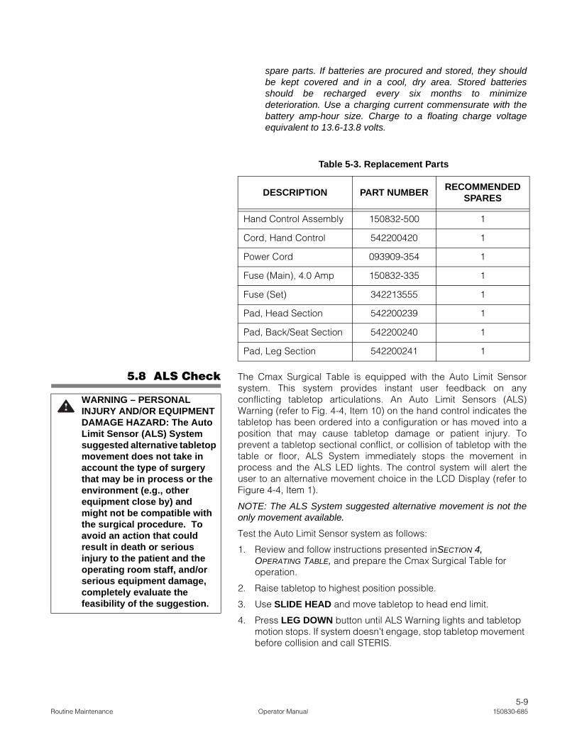
5-9Routine Maintenance Operator Manual 150830-685
spare parts. If batteries are procured and stored, they shouldbe kept covered and in a cool, dry area. Stored batteriesshould be recharged every six months to minimizedeterioration. Use a charging current commensurate with thebattery amp-hour size. Charge to a floating charge voltageequivalent to 13.6-13.8 volts.
5.8 ALS Check The Cmax Surgical Table is equipped with the Auto Limit Sensorsystem. This system provides instant user feedback on anyconflicting tabletop articulations. An Auto Limit Sensors (ALS)Warning (refer to Fig. 4-4, Item 10) on the hand control indicates thetabletop has been ordered into a configuration or has moved into aposition that may cause tabletop damage or patient injury. Toprevent a tabletop sectional conflict, or collision of tabletop with thetable or floor, ALS System immediately stops the movement inprocess and the ALS LED lights. The control system will alert theuser to an alternative movement choice in the LCD Display (refer toFigure 4-4, Item 1).
NOTE: The ALS System suggested alternative movement is not theonly movement available.
Test the Auto Limit Sensor system as follows:
1. Review and follow instructions presented inSECTION 4, OPERATING TABLE, and prepare the Cmax Surgical Table for operation.
2. Raise tabletop to highest position possible.
3. Use SLIDE HEAD and move tabletop to head end limit.
4. Press LEG DOWN button until ALS Warning lights and tabletop motion stops. If system doesn't engage, stop tabletop movement before collision and call STERIS.
Table 5-3. Replacement Parts
DESCRIPTION PART NUMBERRECOMMENDED
SPARES
Hand Control Assembly 150832-500 1
Cord, Hand Control 542200420 1
Power Cord 093909-354 1
Fuse (Main), 4.0 Amp 150832-335 1
Fuse (Set) 342213555 1
Pad, Head Section 542200239 1
Pad, Back/Seat Section 542200240 1
Pad, Leg Section 542200241 1
WARNING – PERSONAL INJURY AND/OR EQUIPMENT DAMAGE HAZARD: The Auto Limit Sensor (ALS) System suggested alternative tabletop movement does not take in account the type of surgery that may be in process or the environment (e.g., other equipment close by) and might not be compatible with the surgical procedure. To avoid an action that could result in death or serious injury to the patient and the operating room staff, and/or serious equipment damage, completely evaluate the feasibility of the suggestion.

5-10150830-685 Operator Manual Routine Maintenance
5.9 LEVEL Check Check the Cmax Surgical Table tabletop LEVEL function as follows:
1. Review and follow instructions presented in SECTION 4, OPERATING TABLE and prepare Cmax Surgical Table for operation.
2. Press LEVEL pushbutton.
NOTE: When operating in REVERSE ORIENTATION, LEVELfunction does NOT include the back section for compliance withanesthesia procedures. Ensure REV. ORIENT is not active.
3. When depressed, tabletop is gradually returned to level or hori-zontal position by aligning tabletop sections in following order:
a. KIDNEY Elevator and lateral tilt.
b. Trendelenburg and back.
c. Leg.
NOTE: The LCD Display values will change accordingly.
4. Use a level and ensure tabletop is level. If not, call STERIS.
5.10 Auxiliary ControlCheck
Check the Cmax Surgical Table auxiliary control system as follows:
1. Review and follow instructions presented in SECTION 4, AUXILIARY CONTROL SYSTEM and prepare the Cmax Surgical Table for auxiliary control system operation.
2. With tabletop at extreme low point, press HEIGHT UP pushbut-ton and pump pedal.
3. Ensure tabletop rises correctly. If not, call STERIS.

6-1Troubleshooting Operator Manual 150830-685
This section of the manual describes the types of table malfunctionswhich may occur and indicates probable causes.
If you are unable to correct the situation following the TroubleshootingCharts (or if a problem occurs which is not described on the charts) orROUTINE MAINTENANCE SECTION of this publication, please contactSTERIS. Service charges may be incurred, consult your warranty fordetails. A trained service technician will promptly place your Cmax™
Surgical Table in proper working order.
NOTE: Never permit unqualified persons to service the table. If you areunable to correct a table malfunction, please contact STERIS.
Calling For Service: First, try to define the situation and determinewhether you can solve it yourself (see Table 6-1 or Table 6-2). If youcan't solve the situation, call STERIS and give the following informationfor the table: model number, serial number, date of purchase.
NOTE: To prevent possible hand control functioning issues, returntable to level between a series of hand control commands.
WARNING – PERSONAL INJURY AND/OR EQUIPMENT DAMAGE HAZARD:
• Failure to perform periodic inspections of the table could result in serious personal injury or table damage.
• Repairs and adjustments to this equipment must be made only by STERIS or STERIS-trained service personnel. Maintenance performed by unqualified personnel or installation of unauthorized parts could cause personal injury, result in improper equipment performance, invalidate the warranty, or result in costly damage. Contact STERIS regarding service options.
CAUTION – POSSIBLE EQUIPMENT DAMAGE: When moving the table to or from the point of use, roll it carefully at moderate speed and only over smooth floors. Maximum floor clearance is 1/4" (6.4 mm). Avoid door and elevator jambs, and obstructions greater than 1/4" (6.4 mm). If necessary, lift table over obstructions, onto trucks, etc. Lift table evenly and only by the table base. DO NOT transport articles (including accessories) on top of the table, and DO NOT use a forklift to move uncrated table.
TROUBLESHOOTING 6
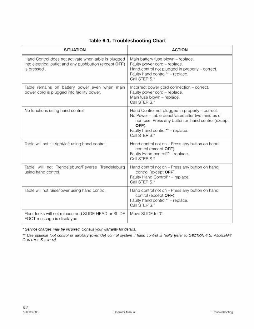
6-2150830-685 Operator Manual Troubleshooting
* Service charges may be incurred. Consult your warranty for details.
** Use optional foot control or auxiliary (override) control system if hand control is faulty [refer to SECTION 4.5, AUXILIARYCONTROL SYSTEM].
Table 6-1. Troubleshooting Chart
SITUATION ACTION
Hand Control does not activate when table is pluggedinto electrical outlet and any pushbutton (except OFF)is pressed .
Main battery fuse blown – replace.Faulty power cord – replace.Hand control not plugged in properly – correct.Faulty hand control** – replace.Call STERIS.*
Table remains on battery power even when mainpower cord is plugged into facility power.
Incorrect power cord connection – correct.Faulty power cord – replace.Main fuse blown – replace.Call STERIS.*
No functions using hand control. Hand Control not plugged in properly – correct.No Power – table deactivates after two minutes of
non-use. Press any button on hand control (except OFF).
Faulty hand control** – replace.Call STERIS.*
Table will not tilt right/left using hand control. Hand control not on – Press any button on hand control (except OFF).
Faulty Hand control** – replace.Call STERIS.*
Table will not Trendeleburg/Reverse Trendeleburgusing hand control.
Hand control not on – Press any button on hand control (except OFF).
Faulty Hand Control** – replace.Call STERIS.*
Table will not raise/lower using hand control. Hand control not on – Press any button on hand control (except OFF).
Faulty hand control** – replace.Call STERIS.*
Floor locks will not release and SLIDE HEAD or SLIDEFOOT message is displayed.
Move SLIDE to 0”.

6-3Troubleshooting Operator Manual 150830-685
Table 6-2. Troubleshooting Chart (LCD Message)
FAULT DISPLAYED FAULT DESCRIPTION FAULT ACTION
1 KEY ONLY Two pushbuttons are pressed at the sametime
Press one button only
DUAL COMMAND Commands are sent from the optional footpedal and the hand control at the sametime.
Hand control has priority
REV ORIENT Flex and Reflex are disabled in reverseorientation.
Press REV. ORIENT
LOW BATT Battery voltage below 23 V. Plug the power cord into facility power andensure Power switch is ON
LOCK AGAIN The pressure switch status does notchange after FLOOR LOCK is pressed orstatus does change and FLOOR LOCK wasnot pressed.
Inspect for oil leakage; verify pressureswitch connect; change floor lock valveblock
WRONG USE Hand control pushbutton is pressed andheld for longer than one minute.
Release button
SENSOR DEF The sensor voltage is out of range (0.3 - 4.7 V)
Check sensor, wire and connection;calibrate sensor; change sensor
SENSOR FAIL Voltage difference between sensor andexpected value by control board.
Calibrate table
BATT FUSE No fuse or blown fuse. Check fuse; plug the power cord into facilitypower
BATT DEF Battery voltages differ by more than 0.6 V. Check voltage of each battery; replacebattery
CHARGER DEF Battery charger is defective or fuse (insidethe charger) is blown.
Check fuse F1; change battery charger
POWER DEF Transformer too hot or fuse F2 is blown.Table still operates on battery power.
Wait for transformer to cool; check fuse F2(inside power supply); replace powersupply
PUMP DEF No hydraulic pump control. Change power supply
VALVE DEF No valve control. Change control board
MOTOR DEF No SLIDE motor control. SLIDE inoperative. Replace sliding board
MOTOR FAIL The power control is always on. SLIDEinoperative.
Replace sliding board
SLIDE DEF No SLIDE control. SLIDE inoperative. Change sliding board
SLIDE FAIL SLIDE continuously operating. SLIDEinoperative.
Replace sliding board
PUMP FAIL Pump does not shut off. Change power supply
BAD VERSION Hand control software version isincompatible with control board softwareversion.
Replace hand control
VOLTAGE PEAK Battery voltage reaches 31 V. Replace power supply
VALVE FAIL Valve does not shut off. Replace control board
SLIDE HEAD or SLIDE FOOT SLIDE is not within 1” (25 mm) of centerposition when unlock floor locks isattempted.
Position SLIDE to 0”.

7-1Disposal Hazards Operator Manual 150830-685
The following materials may be contained within the table. When dis-posing of the table or its parts, ensure the proper disposal of hazard-ous and other regulated waste in compliance with federal, state, andlocal regulations.
Lead Acid (Pb/H2SO4): gelled cell batteries located in the table baseat the head end of the table. Approximate weight 5 lb (2 kg).
Lead (Pb) in Solder: contained in solder on circuit boards and insome miscellaneous wire connections. Minute amounts.
Electronic and Electrical Parts: not known to require special dis-posal at date of this manual.
Metal Parts: made from aluminum (Al), steel (Fe), cast iron (Fe), cop-per (Cu), and copper alloys (Cu/x), plastic, synthetic rubber, plating(Cr, Ni, Zn, Au), and adhesives not known to require special disposalmethods at date of this manual.
Hydraulic Oil: contained in hydraulic components located in thebase, column, leg section, back section, and hydraulic system linesand hoses.
WARNING – DISPOSAL HAZARD: This product contains materials which may require disposal through appropriately licensed and permitted hazardous waste management firms.
CAUTION – POSSIBLE EQUIPMENT DAMAGE: Use of incorrect hydraulic oil may severely damage the table and/or cause malfunction. Contact STERIS for proper hydraulic oil.
DISPOSAL HAZARDS 7