
OPERATOR MANUAL '16' Series - duntonfarms.com · personnel, genuine Mahindra parts and necessary...
140
Transcript of OPERATOR MANUAL '16' Series - duntonfarms.com · personnel, genuine Mahindra parts and necessary...

Click here to go on
INDEX
OPERATOR MANUAL
2816 Gear
'16' Series
Main Menu
Portabl
Zone de texte

16 S
eries, Model - 2
816 4
WD
AB
OU
T TH
IS M
AN
UA
L
Th
is M
an
ual h
as b
een
p
rep
ared
to
assist yo
u in
fo
llo
win
g th
e co
rrect
procedure for break-in, operation and m
aintenance of your new
M
ahindra
tracto
r.
Yo
ur tracto
r h
as b
een
d
esign
ed
an
d b
uilt to
give m
axim
um
p
erfo
rm
an
ce,
with
go
od
fu
el eco
no
my an
d ease o
f o
peratio
n u
nd
er a w
id
e variety o
f
operating conditions. Prior to delivery, the tractor w
as carefully inspected,
both at the factory and by your M
ahindra dealer, to ensure that it reaches
yo
u in
o
ptim
um
co
nd
itio
n. To
m
ain
tain
th
is co
nd
itio
n an
d en
su
re tro
ub
le
free p
erfo
rm
an
ce, it is im
po
rtan
t th
at th
e ro
utin
e services, as sp
ecified
in
this m
anual, are carried out at the recom
mended intervals.
We have enclosed a page on new
tractor inspection sheets. The first sheet
is th
e d
ealer’s co
py an
d sh
ou
ld
b
e rem
oved
b
y th
e d
ealer after th
e
in
sp
ectio
n h
as b
een
carried
o
ut. T
he seco
nd
sh
eet is yo
ur co
py o
f th
e
service perform
ed. Ensure that you &
the dealer sign both copies.
Read
th
is m
an
ual carefu
lly an
d keep
it in
a co
nven
ien
t p
lace fo
r fu
tu
re
referen
ce. If at an
y tim
e yo
u req
uire ad
vice co
ncern
in
g yo
ur tracto
r, d
o
no
t h
esitate to
co
ntact yo
ur au
th
orised
M
ah
in
dra d
ealer. H
e h
as train
ed
personnel, genuine M
ahindra parts and necessary equipm
ents to undertake
all your service requirem
ents.
Mah
in
dra U
SA
In
c’s p
olicy is o
ne o
f co
ntin
uo
us im
pro
vem
en
t, an
d th
e
righ
t to
ch
an
ge p
rices, sp
ecificatio
ns o
r eq
uip
men
ts at an
y tim
e w
ith
ou
t
notice is reserved.
All data given in this book is subject to production variations. D
im
ensions
& w
eigh
t are ap
pro
xim
ate o
nly an
d th
e illu
stratio
ns d
o n
ot n
ecessarily
sh
ow
tracto
rs in
stan
dard
co
nd
itio
n. Fo
r exact in
fo
rm
atio
n ab
ou
t an
y
particular tractor, please consult your M
ahindra dealer.

16 S
eries, Model - 2
816 4
WD
Off-R
oad Diesel E
ngine
Em
ission Control System
Warranty Statem
ent
MIT
SUB
ISHI H
EA
VY
IND
UST
RIE
S, LT
D.
GE
NE
RA
L M
AC
HIN
ER
Y &
SPE
CIA
L V
EH
ICL
E H
EA
DQ
UA
RT
ER
S
MIT
SUB
ISHI
DIE
SEL
EN
GIN
E

16 S
eries, Model - 2
816 4
WD
Man
ufactu
rer Statem
ent
Mitsubishi H
eavy Industries, ltd. (MH
I) will give a w
arranty condition, required by the
U.S
. Environm
ental Protection A
gency(EPA
) and the California A
ir Resource
Board(C
AR
B) to O
riginal Equipm
ent Manufacturers (O
EM
s) for small off-road engines
purchased in 1997 and later which are used in U
.S.A.
It is the OE
Ms responsibility to give the follow
ing warranty to the end-users for sm
all
off-road engines purchased in 1997 and later which are used in U
.S.A.
The m
anufacturer of MH
I small off-road engines has authorized equipm
ent
manufacturers to be the direct contact for all w
arranty and service related questions
and/or repairs. All inquiries should be directed to equipm
ent manufacturers only.
Em
ission Control W
arranty Statement
Applicable only to engines purchased in U
.S.A. in 1997 and thereafter w
hich are used
in U.S.A
..
EPA
emission control defects w
arranty statement – Y
our (Custom
er) defects warranty
rights and obligations:
EPA
and Mitsubishi H
eavy Industries, Ltd. are pleased to explain the em
ission control
system w
arranty on your 1997 and later small off-road engine. In U
.S.A
., new sm
all
off-road engines must be designed, built and equipped to m
eet the EPA
stringent
anti-smog standards. M
itsubishi Heavy Industries, L
td. must w
arrant the emission
control system on your sm
all off-road engine for the periods of time listed below
,
provided there has been no abuse, neglect or improper m
aintenance of your small
off-road engine.
Where a w
arrantable condition exists, the (OE
Ms) w
ill repair your small off-road
engine at no cost to you including diagnosis, parts and labor.
Off-R
oad Diesel E
ngine
Em
ission Control System
Warranty Statem
ent
Em
ission Related System
Defect W
arranty

16 S
eries, Model - 2
816 4
WD
Manufacturer’s E
mission C
ontrol Warranty C
overage
Applicable only to engines purchased in U
.S.A. in 1997 and thereafter w
hich are used
in U.S.A
..
Em
ission control systems w
arranty coverage.
The sm
all off-road engines are warranted as to em
ission control parts defects for a
period, which is prescribed by U
S EPA
CFR
Part 89, subject to provisions as set forth
hereafter. If any covered part on your engine is defective, the part will be repaired by
(OE
Ms).
Ow
ner’s warranty responsibilities:
As the sm
all off-road engine owner, you are responsible for the perform
ance of the
required maintenance listed in your ow
ner’s manual. (O
EM
s) recomm
ends that you
retain all receipts covering maintenance on your sm
all off-road engine. But (O
EM
s)
cannot deny warranty solely for the lack of receipts or for your failure to ensure the
performan ce of all scheduled m
aintenance.
As the sm
all off-road engine owner, you should be aw
are, however, that O
EM
s may
deny you warranty coverage if your sm
all off-road engine or a part has failed due to
abuse, neglect, improper m
aintenance or unapproved modifications.
You are responsible for presenting your sm
all off-road engine to an authorized service
dealer (authorized by OE
Ms) of sm
all off-road engines as soon as a problem exists. T
he
undisputed warranty repairs should be com
pleted in a reasonable amount of tim
e, not
to exceed 30 days. If you have any question regarding your warranty rights and
responsibilities, you should contact (Mahindra, U
SA
Inc) at 1-800-561-9256. The
emission w
arranty is a defects warranty. D
efects are judged on normal engine
performance.
The w
arranty is not related to an in-use emission test.
Specific Warranty P
rovisions
The follow
ing are specific provisions relative to your emissions control system
s
warranty coverage.
Warranted P
arts
Coverage under this w
arranty extends only to the parts listed below (the em
ission
control systems parts) to the extent these parts w
ere present on the engine purchased.

16 S
eries, Model - 2
816 4
WD
Fuel injection system
•Fuel injection pum
p
•Fuel injectors
Inlet system
•Intake m
anifold
Exhaust system
•E
xhaust manifold
Turbocharger system
•T
urbocharger (if equipped)
Miscellaneous item
s used in above systems
•C
ylinder Head G
asket
•V
alve Stem Seal
Length of C
overage
MH
I warrants to the initial ow
ner and each subsequent purchaser that the warranted
parts shall be free from defects in m
aterials and workm
anship which cause the failure
of the warranted part(s) for a period, w
hich is prescribed by US
EPA
CF
R P
art 89,
from the date the engine is delivered to a retail purchaser.
For all engines rated under 19kW
and for constant speed engines rated under 37kW
with rated speeds greater than or equal to 3,000 rpm
, the warranty period is
3,000 hours or 5 years of use, whichever first occurs.
For all other engines rated at or above 19kW, the w
arranty period is 5,000 hours or 7
years of use, whichever first occurs.
No C
harge
Repair or replacem
ent of any warranted part w
ill be performed at no charge to the
owner, including diagnostic labor w
hich leads to the determination that a w
arranted
part is defective, if the diagnostic work is perform
ed at an authorized service dealer of
small off-road engines to w
hom O
EM
s would sell engines.
Claim
s and Coverage E
xclusions
Warranty claim
s shall be filled in accordance with the provisions of the O
EM
s engine
warranty policy. W
arranty coverage shall be excluded failures of warranted parts

16 S
eries, Model - 2
816 4
WD
which are not original O
EM
s parts or because of abu
se, neg
lect or im
pro
per
maintenance as set forth in the O
EM
s engine warranty policy. O
EM
s is not liable to
cover failures of warranted parts caused by the use of add-on, non-original, or m
odified
parts.
Maintenance
Any w
arranted part which is not scheduled for replacem
ent as required maintenance
or which is scheduled only for regular inspection to the effect of “repair or replace as
necessary” shall be warranted as to defects for the w
arranty period. Any w
arranted
part which is scheduled for replacem
ent as required maintenance shall be w
arranted
as to defects only of the period of time up to the first scheduled replacem
ent for that
part. Any replacem
ent part that is equivalent in performance and durability m
ay be
used in the performance of any m
aintenance or repairs. The ow
ner is responsible for
the performance of all required m
aintenance, as defined in the MH
I owner’s m
anual.
Consequential C
overage
Coverage hereunder shall extend to the failure of any engine com
ponents caused by
the failure of any warranted part still under w
arranty.

16 S
eries, Model - 2
816 4
WD
I
REAR
INT
RO
DU
CT
ION
This
instru
ctio
n m
anual c
onta
ins in
form
atio
n o
n th
e o
pera
tion, lu
bric
atio
na
nd
ma
inte
na
nce
of y
ou
r tracto
r. Th
e in
form
atio
n c
on
tain
ed
is c
om
pre
-h
en
siv
e a
nd
esse
ntia
l, an
d is
de
sig
ne
d to
assis
t yo
u, e
ve
n if u
n-
experie
nced, in
utiliz
ing y
our tra
cto
r.H
ow
we
ll yo
ur tra
cto
r co
ntin
ue
s to
giv
e s
atis
facto
ry p
erfo
rma
nce
de
-p
en
ds g
rea
tly u
po
n th
e m
an
ne
r in w
hic
h it is
op
era
ted
. It is, th
ere
fore
,re
qu
este
d th
at th
is m
an
ua
l be
rea
d c
are
fully
an
d k
ep
t rea
dy fo
r use
so
that th
e o
pera
tion a
nd m
ain
tenance s
erv
ice w
ill pro
perly
be c
arrie
d o
ut in
ord
er to
keep th
e tra
cto
r in to
p m
echanic
al c
onditio
n a
t all tim
es.
Should
any in
form
atio
n a
s to
your tra
cto
r be re
quire
d, c
onsult y
our lo
cal
de
ale
r or d
istrib
uto
r sta
ting
the
ma
ch
ine
an
d e
ng
ine
se
rial n
um
be
rs o
fth
e tra
cto
r concern
ed. W
e a
re s
ure
you w
ill be h
appy w
ith y
our tra
cto
r.
NO
TE
: Exp
ressio
ns s
uch
as L
EF
T, R
IGH
T, F
RO
NT, o
r RE
AR
use
d in
this
manual s
hould
be u
nders
tood in
accord
ance w
ith fo
llow
ing ru
les:
FR
ON
T m
eans th
e fro
nt g
rill end w
hile
RE
AR
means th
e liftin
g a
rm e
nd
of th
e tra
cto
r. LE
FT
or R
IGH
T m
ea
ns th
e le
ft or rig
ht h
an
d s
ide
of th
etra
cto
r lookin
g fo
rward
from
opera
tor’s
seat.
INT
RO
DU
CT
ION
RIG
HT
LEFT
FRONT

16 S
eries, Model - 2
816 4
WD
II
SE
RIA
L N
UM
BE
RS
Write
yo
ur m
ach
ine
Mo
de
l Nu
mb
er a
nd
Se
rial N
um
be
rs o
f ma
jor c
om
-p
on
en
ts o
n th
e lin
es p
rovid
ed
. If ne
ed
ed
, giv
e th
ese
nu
mb
ers
to y
ou
rdeale
r when y
ou n
eed p
arts
or in
form
atio
n fo
r your m
achin
e.
1.
TR
AC
TO
R M
OD
EL
NU
MB
ER
________________________________
2.
TR
AC
TO
R S
ER
IAL
NU
MB
ER
________________________________
3.
EN
GIN
E S
ER
IAL
NU
MB
ER
__________________________________
4.
RO
PS
SE
RIA
L N
UM
BE
R____________________________________
SE
RIA
L N
UM
BE
R L
OC
AT
ION
S
TR
AC
TO
R M
OD
EL N
UM
BE
R A
ND
SE
RIA
L N
UM
BE
R P
LA
TE
RO
PS
SE
RIA
L N
UM
BE
R P
LA
TE
SE
RIA
L N
UM
BE
RS
EN
GIN
E S
ER
IAL N
UM
BE
R

16 S
eries, Model - 2
816 4
WD
GE
NE
RA
L T
AB
LE
OF
CO
NT
EN
TS
Sa
fety
/De
ca
ls...............................................................................................1
-19
Sp
ecific
atio
ns
.............................................................................................20
-24
Instru
me
nts
/Co
ntro
ls..................................................................................2
5-4
1
Op
era
ting
Instru
ctio
ns
................................................................................42
-61
Fie
ld O
pe
ratio
n...........................................................................................6
2-7
5
Tire
s/W
he
els
/Sp
acin
g/B
alla
st....................................................................7
1-8
6
Lu
bric
atio
n/F
ilters
/Flu
ids
..........................................................................87-1
13
Ma
inte
na
nce
/Ad
justm
en
ts.....................................................................
11
4-1
20
Ele
ctric
al S
yste
m....................................................................................1
21
-12
8
Sto
rag
e...................................................................................................1
29
-13
0
III

16 S
eries, Model - 2
816 4
WD
RE
ME
MB
ER
:“S
AF
ET
Y” IS
ON
LY
A W
OR
D U
NT
IL IT
IS P
UT
INT
OP
RA
CT
ICE
Imp
rop
er h
an
dlin
g o
f the
tracto
r co
uld
ca
use
an
accid
en
t. Prio
r to th
eopera
tion o
f the tra
cto
r, be s
ure
to re
ad th
is M
anual c
are
fully
and h
ave a
tho
rou
gh
un
de
rsta
nd
ing
of a
ll of th
e c
on
ten
ts. In
pa
rticu
lar, th
e in
stru
c-
tion
s g
ive
n in
this
se
ctio
n e
ntitle
d “S
afe
ty P
reca
utio
ns” m
ust b
e s
trictly
follo
we
d.
A.
GE
NE
RA
L O
PE
RA
TIN
GS
AF
ET
Y P
RE
CA
UT
ION
1.
Observ
e a
ll the s
afe
typre
cautio
ns in
this
manual
when o
pera
ting th
e tra
cto
r.
2.
Opera
te th
e tra
cto
r while
wearin
g tig
ht c
loth
ing th
at
allo
ws e
asy m
ovem
ent.
Avoid
loose ja
ckets
, muffle
rs,
ties, s
carv
es, o
r loose s
hirt
sle
eves to
pre
vent fro
m b
ein
gcaught b
y m
ovin
g p
arts
.
5.
Never a
llow
riders
on th
etra
cto
r, linkage d
raw
bar o
ratta
chm
ent w
hile
travellin
g a
nd
opera
ting th
em
.
3.
Alw
ays w
ork
wh
en
yo
u a
re in
go
od
ph
ysic
al c
on
ditio
n b
yta
kin
g s
uffic
ien
t rest to
avo
ido
ve
rwo
rk.
4.
Do
no
t allo
w c
hild
ren
or a
du
ltsh
avin
g n
o k
no
wle
dg
e o
f the
tracto
r or tra
cto
r op
era
tion
, too
pe
rate
the
tracto
r.
B.
BA
SIC
SA
FE
TY
RE
QU
IRE
-M
EN
TS
FO
R M
AIN
TE
NA
NC
EA
lways fo
llow
these m
ain
te-
nance in
stru
ctio
ns b
efo
reopera
ting th
e tra
cto
r:
1.
Imm
edia
tely
repair th
e h
ead
lights
and w
ork
lam
ps re
quire
dto
confo
rm to
traffic
regula
tions
where
the tra
cto
r is o
pera
ted.
2.
Keep tra
cto
r ste
ps c
lean to
avoid
accid
ents
due to
slip
-p
ag
e.
SAFETY/DECALS_______________________________________________________
SA
FE
TY
PR
EC
AU
TIO
NS
1

16 S
eries, Model - 2
816 4
WD
3.
Cover th
e P
TO
shaft w
ith a
guard
when n
ot u
sin
g.
4.
Be s
ure
to e
ngage th
e b
rake
and lo
wer a
ny a
ttachm
ent o
rim
ple
ment b
efo
redis
assem
blin
g a
ny p
art.
5.
Never a
dju
st o
r serv
ice th
etra
cto
r when it is
in m
otio
n o
rw
hile
the e
ngin
e is
runnin
g.
Alw
ays a
dju
st th
e b
rake o
rclu
tch p
roperly
in a
ccord
ance
with
the a
dju
stin
g p
rocedure
inth
e in
stru
ctio
n b
ook.
6.
Do n
ot re
move th
e ra
dia
tor c
ap
while
the e
ngin
e is
runnin
g.
Shut d
ow
n th
e e
ngin
e a
nd w
ait
until it c
ools
suffic
iently. F
or
rem
oval, tu
rn th
e c
ap to
the firs
tsto
p to
relie
ve p
ressure
.To re
pla
ce th
e c
oola
nt, u
se th
ecoola
nt re
covery
tank.
7.
Hyd
rau
lic o
il or fu
el e
sca
pin
gu
nd
er p
ressu
re c
an
pe
ne
trate
the
skin
, ca
usin
g s
erio
us in
jury.
Be
fore
dis
co
nn
ectin
g o
il or fu
el
line
s, b
e s
ure
to re
lieve
all
pre
ssu
re. B
efo
re re
sto
ring
pre
ssu
re a
fter re
pa
ir, be
su
re a
llco
nn
ectio
ns a
re tig
ht a
nd
all
hyd
rau
lic c
om
po
ne
nts
are
inn
orm
al c
on
ditio
n. If in
jure
d b
yle
ake
d flu
id, s
ee
a d
octo
rim
me
dia
tely
for p
rop
er
trea
tme
nt.
8.
Wh
en
refu
elin
g, b
e p
artic
ula
rlyca
refu
l first to
sto
p th
e e
ng
ine
co
mp
lete
ly to
pre
ve
nt th
e fu
el
from
ign
iting
. Ne
ve
r refu
el in
the
pre
se
nce
of a
n o
pe
n fla
me
or
wh
ile s
mo
kin
g.
SAFETY/DECALS_______________________________________________________
2

16 S
eries, Model - 2
816 4
WD
c)
If dilu
ted s
ulp
huric
acid
has
gotte
n o
n th
e s
kin
of c
loth
ing:
Wash a
way th
e d
ilute
dsulp
huric
acid
com
ple
tely
with
alo
t of c
lean ru
nnin
g w
ate
r and
neutra
lize w
ith s
oap s
olu
tion.
Then rin
se w
ith w
ate
r.
d)
If the d
ilute
d s
ulp
huric
acid
issp
illed
:W
ash a
way w
ith a
lot o
f wate
ror n
eutra
lize w
ith s
lacked lim
eor b
icarb
onate
of s
oda.
10
.Sto
p th
e e
ngin
e a
nd m
ake s
ure
the P
TO
shift l e
ver is
in N
eutra
lbefo
re p
erfo
rmin
g a
ny o
f the
follo
win
g s
erv
ices, in
clu
din
g.
a)
Rem
oval o
f the p
ropelle
r shaft
betw
een P
TO
and a
ny
atta
ch
me
nt.
b)
Adju
stm
ent o
f PT
O d
rive tra
inand h
itch.
c)
Adju
stm
ent o
r cle
anin
g o
f PT
Odriv
en a
ttachm
ent.
11
.The s
teerin
g w
heel a
lways h
as
built-in
pla
y to
som
e e
xte
nt,
whic
h is
require
d fo
r sm
ooth
meshin
g o
f secto
r gear a
nd
pin
ion g
ear.
Alw
ays in
spect th
e a
mount o
fth
e p
lay. D
o n
ot o
pera
te th
etra
cto
r if there
is to
o m
uch o
rto
o little
pla
y in
the s
teerin
g.
b)
If dilu
ted s
ulp
huric
acid
from
the
batte
ry h
as b
een s
wallo
wed:
Rin
se th
e m
outh
with
cle
an
wate
r imm
edia
tely
and d
rink a
lot o
f raw
eggs o
r milk
. Lie
dow
n q
uie
tly.
9.
Befo
re s
tartin
g a
ny w
ork
on
ele
ctric
al e
quip
ment o
r work
that
may c
ause y
ou to
touch th
eele
ctric
al p
art a
ccid
enta
lly, first
dis
connect th
e b
atte
ry c
able
s.
Never re
move th
e ru
bber c
ap
cover a
t the p
ositiv
e te
rmin
al o
fth
e b
atte
ry c
able
end. B
efo
reconnectin
g th
e b
atte
ry to
the
charg
er, m
ake s
ure
that th
echarg
er s
witc
h is
in “O
FF
”p
ositio
n.
Be s
ure
t o c
onnect th
e c
harg
er
to th
e c
orre
ct te
rmin
als
on th
ebatte
ry (p
ositiv
e to
positiv
e,
negativ
e to
negativ
e).
A g
reat a
mount o
f hydro
gen
gas is
genera
ted b
y th
e b
atte
ryw
hen it is
bein
g c
harg
ed. T
ake
pre
cautio
ns a
gain
st fire
: Do n
ot
have a
ny e
xposed fla
me in
the
are
a w
here
you a
re w
ork
ing.
Be s
ure
not to
cause a
ny
leakage o
f the e
lectro
lyte
, sin
ce
it will c
orro
de th
e s
kin
or
clo
thin
g. In
case o
f accid
ent a
sdescrib
ed b
elo
w, im
media
tely
seek firs
t aid
, and s
ee a
docto
rim
media
tely
for p
roper
trea
tme
nt.
a)
If the d
ilute
d s
ulp
huric
acid
from
the b
atte
ry h
as g
otte
n in
to th
ee
ye
s:
Cle
anse th
e e
yes w
ith a
lot o
fcle
an ru
nnin
g w
ate
r for m
ore
than 1
5 m
inute
s, w
hile
openin
gth
e e
yes w
idely.
3
SAFETY/DECALS_______________________________________________________
16 S
eries, Model - 2
816 4
WD
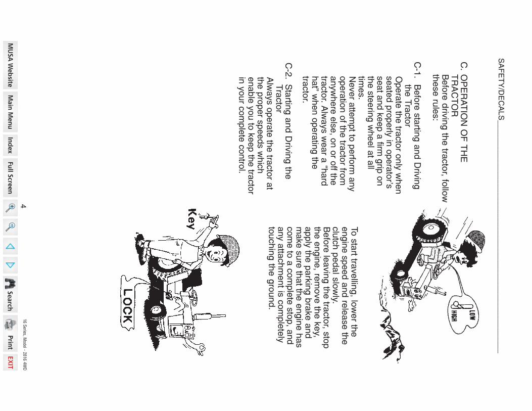
C.
OP
ER
AT
ION
OF
TH
ET
RA
CT
OR
Befo
r e d
rivin
g th
e tra
cto
r, follo
wth
ese ru
les:
C-1
.B
efo
re s
tartin
g a
nd D
rivin
gth
e T
racto
rO
pe
rate
the tra
cto
r only
when
seate
d p
roperly
in o
pera
tor’s
seat a
nd k
eep a
firm g
rip o
nth
e s
teerin
g w
heel a
t all
time
s.
Never a
ttem
pt to
perfo
rm a
ny
opera
tion o
f the tra
cto
r from
anyw
here
els
e, o
n o
r off th
etra
cto
r. Alw
ays w
ear a
“hard
hat” w
hen o
pera
ting th
etra
cto
r.
C-2
.S
tartin
g a
nd D
rivin
g th
eT
racto
rA
lways o
pera
te th
e tra
cto
r at
the p
roper s
peeds w
hic
henable
you to
keep th
e tra
cto
rin
your c
om
ple
te c
ontro
l.
To s
tart t ra
vellin
g, lo
wer th
eengin
e s
peed a
nd re
lease th
eclu
tch p
edal s
low
ly.B
efo
re le
avin
g th
e tra
cto
r, sto
pth
e e
ngin
e, re
move th
e k
ey,
apply
the p
ark
ing b
rake a
nd
make s
ure
that th
e e
ngin
e h
as
com
e to
a c
om
ple
te s
top, a
nd
any a
ttachm
ent is
com
ple
tely
touchin
g th
e g
round.
4
SAFETY/DECALS_______________________________________________________
16 S
eries, Model - 2
816 4
WD
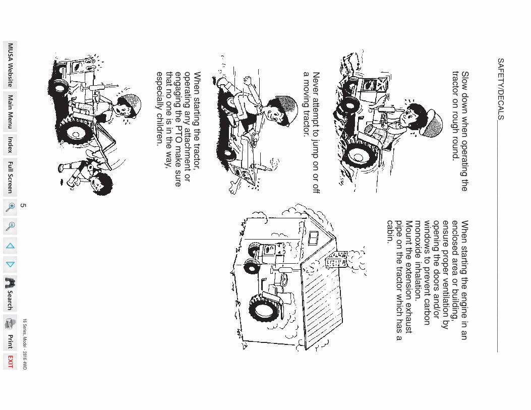
Slo
w d
ow
n w
hen o
pera
ting th
etra
cto
r on ro
ugh ro
und.
Never a
ttem
pt to
jum
p o
n o
r off
a m
ovin
g tra
cto
r.
When s
tartin
g th
e tra
cto
r,opera
ting a
ny a
ttachm
ent o
rengagin
g th
e P
TO
make s
ure
that n
o o
ne is
in th
e w
ay,
especia
lly c
hild
ren.
When s
tartin
g th
e e
ngin
e in
an
enclo
sed a
rea o
r build
ing,
ensure
pro
per v
entila
tion b
yopenin
g th
e d
oors
and/o
rw
indow
s to
pre
vent c
arb
on
monoxid
e in
hala
tion.
Mount th
e e
xte
nsio
n e
xhaust
pip
e o
n th
e tra
cto
r whic
h h
as a
ca
bin
.
5
SAFETY/DECALS_______________________________________________________

16 S
eries, Model - 2
816 4
WD
C-3.
Tra
vellin
g o
n R
oa
ds a
nd
Stre
ets
For trave
lling
on
roa
ds a
nd
streets, be sure to lock bothbrake p
ed
als to
ge
the
r be
fore
driving
to p
reve
nt e
ithe
r bra
kefrom
actin
g in
de
pe
nd
en
tly.
C-4.
Steering and T
urning theT
racto
r
Never operate the differential
lock while driving at high speed
or travelling on
the
roa
d. F
or
driving the 4-WD
tractor on theroad, be sure to place the 4-W
Dshift lever in O
FF
position.
Slow
down your tractor and
disengage the differential lockbefore going into a turn, beingcareful to prevent anyattachm
ents mounted on the
front or rear from hitting anyone
or anything.
C-5.
Towing and O
perating onH
illsF
or towing w
ork on downw
ardslope, place the shift lever inlow
speed and use enginebrake.
Never try to reduce the speed
with brake only. Tow
ing aheavy object on a hill is highlyhazardous. W
iden the tread ofthe tractor and m
ount the wheel
weight or chassis w
eight toincrease the stability andoperate w
ith extra precaution.
6
SAFETY/DECALS_______________________________________________________

16 S
eries, Model - 2
816 4
WD
When operating the tractor on
either a steep slope or flatground, be sure not to suddenlysteer, brake, clutch or operateattachm
ents.D
o not operate the tractor at theedge of cliff or steep slope. B
eparticularly careful right afterthe rain w
hen soil is soft andm
ay give way easily.
For tow
ing, be sure to use thedraw
bar only. Set the hitch
point below the center line of
the rear axle. When using a
chain, never try to move
forward abruptly.
When using agricultural
chemicals w
ith an attachment
on the tractor, always follow
theinstructions in the m
anual forthe attachm
ent as well as the
instructions provided by thechem
ical manufacturer.
C-6.
Using A
ttachment
To mount or operate
attachm
ent, follow the instruc-
tion m
anual for the particularattachm
ent for safe operation.
Avoid operating the tractor on
an extreme slope that appears
hazardous, when forced to
operate on such slope, useextra care. D
riving forward out
of a ditch or mired condition or
up a steep slope could causetractor to tip over rearw
ard.B
ack out of such situation ifpossible. If the situation doesnot perm
it you to back out, usethe front w
heel weight or the
chas sis weight for balancing the
tractor lengthwise. A
lso in caseany extra-heavy rear m
ountingattachm
ent is used, try to obtainbetter balance in this m
anner.
7
SAFETY/DECALS_______________________________________________________

16 S
eries, Model - 2
816 4
WD
DE
CA
LS
IMP
OR
TA
NT: In
sta
ll ne
w d
eca
ls if th
e o
ld d
eca
ls a
re d
estro
ye
d, lo
st,
pa
inte
d o
ve
r or c
an
no
t be
rea
d. W
he
n p
arts
are
rep
lace
d th
at h
ave
decals
, make s
ure
you in
sta
ll a n
ew
decal w
ith e
ach n
ew
part.
NO
TE
: New
decals
are
availa
ble
from
your D
eale
r.
EX
PL
OS
IO
N A
ND
IN
JU
RY
CA
N R
ES
ULT
F
RO
M U
SE
OF
S
TA
RT
IN
G A
ID
S W
IT
H
HO
T G
LO
W P
LU
GS
.
DO
NO
T IN
JE
CT
GA
SO
LIN
E
OR
ET
HE
R I
N A
IR
IN
TA
KE
.
WA
RN
ING
321-6864
WA
RN
ING
BA
TT
ER
IES
CO
NTA
IN A
CID
AN
D E
XP
LO
SIV
EG
AS
. E
XP
LO
SIO
N
CA
N
RE
SU
LT
F
RO
MS
PA
RK
S, F
LA
ME
S, O
R W
RO
NG
CA
BLE
CO
N-
NE
CT
ION
S.
TO
C
ON
NE
CT
JU
MP
ER
C
AB
LE
SO
R C
HA
RG
ER
, S
EE
M
AN
UA
L(S
) F
OR
T
HE
CO
RR
EC
T
PR
OC
ED
UR
E.
FA
IL
UR
E
TO
FO
LL
OW
T
HE
A
BO
VE
IN
ST
RU
CT
ION
S C
AN
CA
US
E S
ER
IOU
S P
ER
SO
NA
L IN
JU
RY
O
RD
EA
TH
.
321-6754
8
SAFETY/DECALS_______________________________________________________

16 S
eries, Model - 2
816 4
WD
RO
TA
TIN
G M
AC
HIN
E P
AR
TS
STA
Y C
LE
AR
, KE
EP
SH
IEL
DS
INS
TA
LL
ED
TO
H
EL
P
PR
OT
EC
T
FR
OM
C
LO
TH
ING
EN
TA
NG
LE
ME
NT
A
ND
IN
JU
RY.
WA
RN
ING
321-3710
9
SAFETY/DECALS_______________________________________________________

16 S
eries, Model - 2
816 4
WD
Fold
able
RO
PS
Fra
me
RO
PS
is fo
lda
ble
so
tha
t the
tracto
r ca
n b
e o
pe
rate
d in
pla
ce
s s
uch
as
orc
ha
rds w
he
re th
e h
eig
ht is
restric
ted
. Se
e F
old
ing
the
RO
PS
in th
ism
an
ua
l.
Norm
al O
pera
ting P
ositio
n
For n
orm
al o
pera
tion, in
clu
din
g tra
nsport, a
lways u
se th
e fo
ldable
RO
PS
in th
e s
ecu
red
up
righ
t po
sitio
n w
ith a
faste
ne
d s
ea
t be
lt for fu
ll rollo
ve
rp
rote
ctio
n.
Wh
en
imp
rop
erly
op
era
ted
, this
tracto
r can
roll o
ver o
r up
set. U
se o
fth
e R
OP
S a
nd
seat b
elt m
inim
ize th
e p
ossib
ility o
f inju
ry o
r death
ifro
llover o
r up
set o
ccu
rs. F
or lo
w c
leara
nce u
se o
nly, th
e R
OP
S c
an
be lo
were
d. N
o p
rote
ctio
n is
pro
vid
ed
in th
is p
ositio
n a
nd
the s
eat
belt s
ho
uld
no
t be fa
ste
ned
. Fo
r all o
ther u
ses, s
ecu
re th
e R
OP
S in
the u
prig
ht p
ositio
n a
nd
faste
n th
e s
eat b
elt.
M1
67
A
RO
LL O
VE
R P
RO
TE
CT
IVE
ST
RU
CT
UR
E (R
OP
S)
10
SAFETY/DECALS_______________________________________________________
16 S
eries, Model - 2
816 4
WD
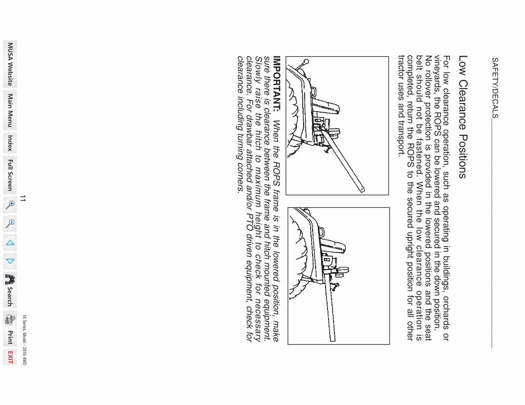
Low
Cle
ara
nce P
ositio
ns
For lo
w c
leara
nce o
pera
tion, s
uch a
s o
pera
ting in
build
ings, o
rchard
s o
rvin
eyard
s, th
e R
OP
S c
an b
e lo
were
d a
nd s
ecure
d in
the d
ow
n p
ositio
n.
No
rollo
ve
r pro
tectio
n is
pro
vid
ed
in th
e lo
we
red
po
sitio
ns a
nd
the
se
at
be
lt sh
ou
ld n
ot b
e fa
ste
ne
d. W
he
n th
e lo
w c
lea
ran
ce
op
era
tion
iscom
ple
ted, re
turn
the R
OP
S to
the s
ecure
d u
prig
ht p
ositio
n fo
r all o
ther
tracto
r uses a
nd tra
nsport.
IMP
OR
TA
NT: W
hen th
e R
OP
S fra
me is
in th
e lo
were
d p
ositio
n, m
ake
sure
there
is c
leara
nce b
etw
een th
e fra
me a
nd h
itch m
ounte
d e
quip
ment.
Slo
wly
rais
e th
e h
itch
to m
axim
um
he
igh
t to c
he
ck fo
r ne
ce
ssa
rycle
ara
nce. F
or d
raw
bar a
ttached a
nd/o
r PT
O d
riven e
quip
ment, c
heck fo
rcle
ara
nce in
clu
din
g tu
rnin
g c
orn
ers
.
11
SAFETY/DECALS_______________________________________________________

16 S
eries, Model - 2
816 4
WD
RO
PS
is a
sp
ecia
l sa
fety
un
it. Afte
r an
accid
en
t the
RO
PS
mu
st b
ere
pla
ced s
o th
at y
ou w
ill get th
e s
am
e p
rote
ctio
n a
s a
new
RO
PS
.R
OP
S, th
e s
ea
t, the
se
at b
elts
an
d a
ll the
mo
un
ting
, acce
sso
ries a
nd
wirin
g in
sid
e th
e o
pe
rato
rs p
rote
ctiv
e a
rea
mu
st b
e c
are
fully
ch
ecke
da
fter a
tracto
r accid
en
t an
d a
ll pa
rts w
ith d
am
ag
e s
ho
uld
be
rep
lace
dim
media
tely. D
O N
OT
TR
Y T
O M
AK
E R
EP
AIR
S O
R W
ELD
RO
PS
.
Tra
cto
r Roll O
ver
Safe
ty R
ule
s
1.
Do
no
t ma
ke
mo
dific
atio
ns to
the
RO
PS
. Exa
mp
le, w
eld
ing
an
accessory
to th
e R
OP
S, o
r drillin
g a
hole
in th
e R
OP
S.
2.
Sp
ecia
l faste
ne
rs a
re u
se
d to
insta
ll the
op
era
tor p
rote
ctiv
e p
arts
.R
ep
lace
me
nt p
arts
mu
st b
e th
e s
am
e a
s g
ive
n in
the
Pa
rts C
ata
log
for y
our tra
cto
r.
RO
PS
Label
1.
RO
PS
is e
quip
ped w
ith a
RO
PS
label.
2.
Th
e la
be
l co
nta
ins th
e R
OP
S s
eria
l nu
mb
er a
nd
ap
plic
ab
le s
tan
d-
ard
s.
12
SAFETY/DECALS_______________________________________________________

16 S
eries, Model - 2
816 4
WD
To
fold
the
RO
PS
, pu
t the
tracto
r on
leve
l gro
un
d, p
ut th
e ra
ng
e s
hift
lever in
the L
positio
n, a
pply
the p
ark
bra
ke a
nd s
top th
e e
ngin
e.
Fold
ing th
e R
OP
S
IMP
OR
TA
NT: D
o n
ot fo
ld th
e R
OP
S w
ith a
sunshade in
sta
lled.
Rem
ove th
e lo
ck p
ins.
LO
CK
P
IN
LO
CK
N
UT
ST
EP
2
LO
CK
P
IN
Lo
ose
n th
e ja
m n
ut o
n th
e lo
ck
bo
lts.
Rem
ove th
e lo
ck n
uts
.
Lo
ose
n th
e lo
ck b
olts
en
ou
gh
top
erm
it th
e p
os
ition
p
in to
b
ere
mo
ve
d. D
O N
OT
rem
ove
pin
suntil S
TE
P 6
.
ST
EP
4
LO
CK
B
OL
T
RO
PS
BA
R(N
OR
MA
L O
PE
RA
TIN
G P
OS
ITIO
N)
JA
M N
UT
LO
CK
B
OL
T
PO
SIT
ION
P
IN
ST
EP
1
LO
CK
N
UT
JA
M N
UT
LO
CK
B
OL
T
ST
EP
3
13
SAFETY/DECALS_______________________________________________________

16 S
eries, Model - 2
816 4
WD
Tig
hte
n th
e ja
m n
ut o
n th
e lo
ck
bo
lts to
a to
rqu
e o
f 33
to 4
0 lb
.ft(4
4 to
54 N
.m).
Insta
ll the p
ositio
n p
ins.
Wh
ile
ho
ldin
g
the
R
OP
S
ba
r,C
AR
EF
UL
LY
rem
ove
the
po
sitio
np
ins.
Insta
ll the lo
ck p
ins.
CA
RE
FU
LLY
mo
ve
the
RO
PS
bar to
the d
esire
d p
ositio
n.
Insta
ll lock n
uts
an
d tig
hte
n to
ato
rqu
e o
f 33
to 4
0 lb
ft (44
to 5
4N
m).
NO
TE
:T
he
lo
ck
n
uts
c
an
b
eo
mitte
d
for
op
era
tor
co
nv
en
-ie
nce
, if the
RO
PS
is fo
lde
d fre
-quently.
When th
e lo
w c
leara
nce tra
cto
r opera
tion is
com
ple
ted, re
turn
the R
OP
Sto
the s
ecure
d u
prig
ht p
ositio
n.
ST
EP
9
ST
EP
7S
TE
P 1
0
LO
W C
LE
AR
AN
CE
PO
SIT
ION
SP
OS
ITIO
N P
IN
JA
M N
UT
LO
CK
B
OL
T
ST
EP
5
LO
CK
PIN
LO
W C
LE
AR
AN
CE
PO
SIT
ION
S
ST
EP
6
RO
PS
BA
R
PO
SIT
ION
PIN
RO
PS
BA
R
TO
TH
E L
OW
PO
SIT
ION
LO
CK
N
UT
LO
CK
P
IN
ST
EP
8
14
SAFETY/DECALS_______________________________________________________

16 S
eries, Model - 2
816 4
WD
RO
PS
BA
R
(NO
RM
AL
OP
ER
AT
ING
PO
SIT
ION
)
LO
CK
PIN
PO
SIT
ION
PIN
JA
M N
UT
LO
CK
BO
LT
LO
CK
NU
T
For n
orm
al o
pera
tion, th
e R
OP
S m
ust b
e in
th
e secure
d uprig
ht
positio
n
Pla
ce th
e tr
acto
r on le
vel
ground,
put
the range shift
lever in
th
e L
positio
n, a
pply
the p
ark
bra
ke a
nd s
top th
e e
ngin
e.
ST
EP
1
Rem
ove th
e lo
ck n
uts
.R
em
ove th
e lo
ck p
ins.
LO
CK
PIN
LO
CK
NU
T
ST
EP
2
Securin
g th
e R
OP
S in
the U
prig
ht P
ositio
n
15
SAFETY/DECALS_______________________________________________________

16 S
eries, Model - 2
816 4
WD
RO
PS
BA
R
CA
RE
FU
LLY
rais
e th
e R
OP
S b
ar
to th
e u
prig
ht p
ositio
n.
Wh
ile h
old
ing
th
e R
OP
S b
ar,
CA
RE
FU
LLY
rem
ove
the
po
sitio
np
ins.
Insta
ll the
po
sitio
n p
ins. If b
oth
pin
s c
an
be
insta
lled
, co
ntin
ue
toS
TE
P 1
0.
ST
EP
3
PO
SIT
ION
PIN
ST
EP
6
If the
po
sitio
n p
ins
ca
nn
ot b
ein
sta
lled
, CA
RE
FU
LLY
low
er th
eR
OP
S
ba
r to
th
e
ho
rizo
nta
lp
ositio
n.
ST
EP
4
ST
EP
7T
O T
HE
UP
RIG
HT
PO
SIT
ION
Loosen th
e lo
ck b
olts
.
Lo
ose
n th
e ja
m n
ut o
n th
e lo
ck
bo
lts.
LO
CK
BO
LT
ST
EP
5
ST
EP
8
JA
M N
UT
LO
CK
BO
LT
PO
SIT
ION
PIN
RO
PS
BA
R
RO
PS
BA
R
16
SAFETY/DECALS_______________________________________________________

16 S
eries, Model - 2
816 4
WD
RO
PS
BA
R
LO
CK
PIN
LO
CK
NU
T
TO
TH
E U
PR
IGH
T P
OS
ITIO
N
ST
EP
9S
TE
P 1
0
RO
PS
BA
RR
OP
S B
AR
PO
SIT
ION
PIN
CA
RE
FU
LL
Y m
ov
e th
e R
OP
Sbar to
the u
prig
ht p
ositio
n.
Insta
ll the p
ositio
n p
ins. A
lign th
eh
ole
s o
f the
po
sitio
n p
ins a
nd
RO
PS
bra
cke
ts s
o th
at th
e lo
ck
pin
s c
an b
e in
sta
lled e
asily.
PO
SIT
ION
PIN
JA
M N
UT
LO
CK
BO
LT
(NO
RM
AL
OP
ER
AT
ING
PO
SIT
ION
)
17
SAFETY/DECALS_______________________________________________________

16 S
eries, Model - 2
816 4
WD
ST
EP
15
Fo
r trac
tors
with
a s
un
sh
ad
e,
ST
EP
12, S
TE
P 1
3 a
nd S
TE
P 1
4m
ust b
e fo
llow
ed
for u
sin
g th
elo
ck b
olts
. On
tracto
rs w
itho
ut a
su
nsh
ad
e, it is
reco
mm
en
de
dth
at
ST
EP
1
2,
ST
EP
1
3
an
dS
TE
P 1
4 b
e u
se
d, h
ow
eve
r, ifR
OP
S is
fold
ed fre
quently
for lo
wcle
ara
nce
tracto
r op
era
tion
, the
follo
win
g s
etu
p m
ay b
e u
sed:
ST
EP
11
Fo
r tracto
rs w
itho
ut a
su
nsh
ad
ea
nd
for o
pe
rato
rs w
ho
freq
ue
ntly
fold
the
RO
PS
for lo
w c
lea
ran
ce
trac
tor
op
era
tion
, c
on
tinu
e to
ST
EP
15.
ST
EP
12
Lo
ose
n th
e ja
m n
ut o
n th
e lo
ck
bo
lts.
ST
EP
13
Tig
hte
n th
e lo
ck b
olt o
nly
enough
to re
mo
ve
the
loo
se
ne
ss o
f the
hin
ge
join
t. Pu
sh
the
RO
PS
ba
rfo
rwa
rd to
pe
rmit th
e p
ositio
n p
into
be
rota
ted
an
d re
mo
ve
d b
yh
an
d.
Tig
hte
n th
e ja
m n
ut o
n th
e lo
ck
bolts
to a
torq
ue o
f 33 to
40 lb
ft(4
4 to
54 N
m)
ST
EP
16
Ch
eck th
e a
sse
mb
ly. If the
po
si-
tion
pin
s a
re to
o tig
ht o
r loo
se
,re
peat S
TE
P 1
5.
Tig
hte
n th
e lo
ck b
olts
to a
torq
ue
of 3
3 to
40 lb
ft (44 to
54 N
m).
ST
EP
14
Tig
hte
n th
e ja
m n
ut o
n th
e lo
ck
bo
lts to
a to
rqu
e o
f 33
to 4
0 lb
ft(4
4 to
54 N
m). C
ontin
ue to
ST
EP
17
.
JA
M N
UT
LO
CK
BO
LT
LO
CK
BO
LT
LO
CK
BO
LT
JA
M N
UT
LO
CK
BO
LT
JA
M N
UT
LO
CK
BO
LT
18
SAFETY/DECALS_______________________________________________________

16 S
eries, Model - 2
816 4
WD
Ro
llov
er p
rote
ctio
n is
pro
vid
ed
on
ly w
ith p
rop
er a
ss
em
bly
. Lo
ck
pin
s, h
ing
e p
ins a
nd
po
sitio
n p
ins m
ust b
e in
pla
ce. C
orre
ct p
arts
may b
e o
bta
ined
from
yo
ur d
eale
r.M
23
4A
RO
PS
BA
R
(NO
RM
AL
OP
ER
AT
ING
PO
SIT
ION
)
LO
CK
PIN
PO
SIT
ION
PIN
JA
M N
UT
LO
CK
BO
LT
LO
CK
NU
T
ST
EP
18
ST
EP
17
Insta
ll the lo
ck p
ins.
Insta
ll the
lock n
uts
. Tig
hte
n th
en
uts
to a
torq
ue
of 3
3 to
40
lb ft
(44 to
54 N
m).
NO
TE
: Th
e lo
ck n
ut in
sta
llatio
ncan b
e o
mitte
d fo
r opera
tor c
onve-
nie
nc
e if
the
R
OP
S is
fo
lde
dfre
qu
en
tly.
LO
CK
NU
TL
OC
K P
IN
19
SAFETY/DECALS_______________________________________________________

16 S
eries, Model - 2
816 4
WD
SPECIFICATIO
NS_______________________________________________________
Type ........................................................... Three C
ylinder, Four S
troke Cycle,
Valve in C
ylinder Head, C
ross F
low P
ortingF
iring Order....................................................................................1 —
3— 2
Bore
................................................................. 78mm
(3.071 inch)S
troke.....................................................................92m
m (3.622 inch)
Piston D
isplacement
.......................................................1318 cm3 (80.43 C
ubic inch)C
ompression R
atio.........................................................................22.0 to 1G
overnor Engine S
peed Without Load............................... 2730 to 2780 R
PM
Rated E
ngine Speed........................................................................ 2600 R
PM
Engine Idle S
peed................................................................. 950 to 1000 RP
M*M
aximum
Horsepow
er (Manufacturing R
ating)................................................................. 28H
P at 2600 R
PM
Valve C
learance (Intake and Exhaust C
old Engine)
.......................................................0.25mm
(0.010 inch)IM
PO
RTA
NT:
Va
lve cle
ara
nce
ad
justm
en
t mu
st be
ma
de
wh
en
the
engine is not running and is cold.
Ge
ne
ral
DIE
SE
L EN
GIN
E
Engine Lubrication S
ystemO
il Pressure
....................................392kPa (57P
SI) at 2500
En
gin
e R
PM
with
10
W–
30
Oil
at 90°C (194°F
)
Fuel S
ystem
Fuel Injection P
ump.............................................B
OS
CH
M P
lunger In Line N
IPP
ON
DE
NS
OInjection P
ump Tim
ing...................... 17 D
egrees Before Top D
ead Center (B
TD
C)
Fuel Injectors
...............T
hrottle Type, NIP
PO
ND
EN
SO
*Manufacturer’s estim
ate under standard condition and subject to change without prior notice.
20

16 S
eries, Model - 2
816 4
WD
Air Intake S
ystem
Type ..........................................................Dry Type A
ir Cleaning S
ystem
Coolin
g S
yste
m
Typ
e.................................................
Pre
ssu
re S
yste
m, T
he
rmo
sta
t Co
n-
trolle
d B
ypass, Im
pelle
r Type P
um
pR
ad
iato
r.................................................
Corru
gate
d a
nd L
ouver F
in T
ype
Th
erm
osta
t......................................Sta
rt to O
pen a
t Appro
x. 8
2°C(1
80°F
)F
ully
Open a
t 95°C
(203°F
)P
ressure
Cap
...............................................................88
.3 k
Pa
(12.8
PS
I)W
ate
r Tem
pera
ture
...............................Therm
om
ete
r on In
stru
ment P
anel
PO
WE
R T
RA
IN
Tra
cto
r Bra
kes
Typ
e.............................................................................W
et D
isk P
late
Type
Op
era
tion
.................................................................................. Me
ch
an
ica
lP
ark
ing B
rakes.................................................. H
and O
pera
ting L
ock T
ype
Tra
nsm
issio
n
Typ
eGear D
rive............................... S
ynchro
mesh o
n G
ear S
hift w
ith T
hre
eR
anges o
f Sele
ctiv
e S
lidin
g G
ears
Gear S
ele
ctio
nG
ear D
rive....................... 9
Speeds F
orw
ard
and 3
Speeds R
evers
e
Shift C
ontro
lG
ea
r Driv
e ......................A
ctu
ate
d b
y T
wo S
hift L
evers
on th
e L
HF
en
de
r
PT
O H
P......................................................................................... 2
3.0
HP
21
SPECIFICATIO
NS_______________________________________________________

16 S
eries, Model - 2
816 4
WD
SPECIFICATIO
NS_______________________________________________________
Clu
tch
Type, D
iam
ete
rG
ear D
rive
.....................................D
ry, Du
al D
isc, D
iaphra
gm
Type,
215 m
m (8
.46 In
ch)
Op
era
tion
...................................................................................M
ech
an
ica
l
22
Mechanic
al F
ront D
rive (M
FD
)
Fro
nt A
xle
.............................................Sp
iral B
evel G
ear T
ype D
iffere
ntia
lw
ith B
evel G
ear T
ype R
eductio
ns
Diffe
rentia
l Lock
Ge
ar D
rive
.....................................C
on
trolle
d b
y p
ed
al o
n th
e R
HS
tep a
nd M
echanic
ally
Actu
ate
d
Ste
erin
g
Type o
f Ste
erin
g.................................................................
Hyd
rosta
ticT
yp
e
Hitc
h S
yste
m
Typ
e........................................................................
Th
ree
Poin
t, Cate
gory
IType C
ontro
l........................................................................P
ositio
n C
ontro
lType V
alv
e........................................T
hre
e P
ositio
ns, L
ift, Hold
and lo
wer
Liftin
g C
apacity
at 2
4” b
ehin
d L
ift Poin
t (Per A
SA
E S
349.1
).....................................................................................
75
0 k
g (1
653 L
b)
Type o
f Cylin
der..............................................................S
ingle
Actin
g T
ype

16 S
eries, Model - 2
816 4
WD
Hyd
rau
lic S
yste
m
Hydra
ulic
Pum
p T
ype ..................... F
ront M
ounte
d, E
ngin
e D
riven, P
res-
sure
Loadin
g G
ear T
ype
Ca
pa
city
Pum
p fo
r Thre
e P
oin
t Hitc
h....................................2
9.6
l /m
in. (7
.8G
PM
)at 2
600 E
ngin
eR
PM
Pum
p fo
r Pow
er S
teerin
g..........................................1
3.4
l /m
m.(3
.5G
PM
)at 2
600 E
ngin
eR
PM
Maxim
um
Syste
m P
ressure
.......................................... 14710 k
Pa (2
133 P
SI)
Rem
ote
Hydra
ulic
Contro
l Valv
e (O
PT
ION
AL) ........... O
ne D
ouble
actin
g T
ype
.............................................................................Auxilia
ry V
alv
e A
vaila
ble
Auxilia
ry C
onnecto
r .......................................................F
ront H
ydra
ulic
Blo
ck
Connecto
r Siz
e .............................................................. 9
.5 m
m (3
/8in
ch)
Re
ar P
ow
er T
ake
off (P
TO
)
PT
O T
ype
Gear D
rive ................................................................................. L
ive P
TO
Lo
ca
tion
................................................................At th
e re
ar o
f tran
sm
issio
nR
ota
tion
...........................................................Clo
ckw
ise
from
rea
r of tra
cto
rS
ha
ft Siz
e......................................3
4.9
mm
(1.3
75
Inch
) Dia
me
ter, 6
Sp
line
sS
pe
ed
............................................................5
40
RP
M a
t 23
76
En
gin
e R
PM
Mid
Pow
er T
akeoff (P
TO
)(OP
TIO
NA
L)
PT
O T
ype
Ge
ar D
rive
..................................................................................Liv
e P
TO
Lo
ca
tion
..........................................................At th
e B
otto
m o
f Tra
nsm
issio
nR
ota
tion
........................................................C
lockw
ise
from
Re
ar o
f Tra
cto
rS
ha
ft Siz
e........................................
25
.4 m
m (1
Inch
) Dia
me
ter, 1
5 S
plin
es
Sp
ee
d..........................................................
20
00
RP
M a
t 26
32
En
gin
e R
PM
Dra
wb
ar
Typ
e................................................................................................F
ixe
d T
yp
eD
ista
nce
from
Hitc
h H
ole
to th
e E
ND
of P
TO
Sh
aft
....8
5 m
m (3
.34
6 in
ch
)M
axim
um
Ve
rtica
l Lo
ad
on
Dra
wb
ar
....................................13
6kg
(30
0 lb
s)
23
SPECIFICATIO
NS_______________________________________________________

16 S
eries, Model - 2
816 4
WD
OV
ER
AL
L L
EN
GT
H(T
o e
nd
of lo
we
r link)
OV
ER
AL
L W
IDT
H(T
o e
nd
of tire
)
HE
IGH
T
(To to
p o
f rops)
WH
EE
LB
AS
E
GR
OU
ND
CL
EA
RA
NC
E
TU
RN
ING
RA
DIU
S(W
ith b
rake a
ssis
tance)
WE
IGH
T
29
20
mm
11
5.0
inc
h
13
80
mm
54
.3in
ch
21
40
mm
84
.3in
ch
16
50
mm
65
.0in
ch
33
0m
m1
3.0
inc
h
24
00
mm
94
.5in
ch
10
50
kg
23
15
lbs
24
DIM
ENSIO
NS_______________________________________________________

16 S
eries, Model - 2
816 4
WD
INS
TR
UM
EN
TS
AN
D IN
DIC
AT
OR
S
1.
TA
CH
OM
ET
ER
AN
D H
OU
RM
ET
ER
– T
he
tach
om
ete
r sh
ow
s th
eengin
e s
peed in
revolu
tions p
er
min
ute
(RP
M). A
sym
bol o
n th
efa
ce
in
dic
ate
s
the
c
orre
ct
Po
we
r Ta
ke
off (P
TO
) op
era
ting
sp
ee
d. T
he
ho
urm
ete
r sh
ow
sth
e h
ou
rs a
nd
ten
ths o
f ho
urs
that th
e e
ngin
e h
as o
pera
ted a
tan a
vera
ge R
PM
.
Ye
llow
line
A s
ho
ws th
e 5
40
rpm
of th
e R
ea
rP
TO
speed.
Yello
w lin
e B
show
s th
e 2
000 rp
m o
f the M
IDP
TO
speed.25
INS
TR
UM
EN
TS
/C
ON
TR
OL
S _
__
__
__
__
__
__
__
__
__
__
__
__
__
__
__
__
__
__
__
__
__
__
_

16 S
eries, Model - 2
816 4
WD
Th
e p
oin
ter is
in th
is a
rea
wh
en
the
en
gin
e is
co
ol
be
fore
an
d im
me
dia
tely
afte
r sta
rting
. Ru
n th
ee
ng
ine
at 1
50
0 R
PM
with
ou
t loa
d u
ntil th
e p
oin
ter
ind
ica
tes th
e g
ree
n a
rea
.T
he
po
inte
r is in
this
are
a w
he
n th
e c
oo
lan
tte
mp
era
ture
is p
rop
er d
urin
g e
ng
ine
op
era
tion
.If th
e e
ng
ine
ove
rhe
ats
, the
po
inte
r mo
ve
s rig
ht
into
this
are
a.
In th
is c
ase
run
the
en
gin
e a
t 15
00
RP
M w
itho
ut
loa
d u
ntil th
e p
oin
ter in
dic
ate
s th
e g
ree
n a
rea
. Ifth
e p
oin
ter s
till sta
ys in
the
red
are
a a
fter th
ree
tofiv
e m
inu
tes, s
top
the
en
gin
e im
me
dia
tely
an
dch
eck fo
r the
ca
use
.
3. F
UE
L G
AU
GE
– T
he
me
ter s
ho
ws h
ow
mu
ch
fue
l is in
the
tan
k. F
ue
lle
ve
l is s
ho
wn
by th
ree
po
sitio
ns.
.............F
ue
l is n
ee
de
d.
Fu
el ta
nk is
ha
lffille
d w
ith fu
el.
.............F
ue
l tan
k is
full.
NO
TE
: T
he
po
inte
r ca
n b
e in
an
y p
o-
sitio
n w
he
n th
e s
tarte
r ke
y s
witc
h is
in th
e O
FF
po
sitio
n. T
o g
et a
fue
l leve
lin
dic
atio
n, tu
rn th
e s
tarte
r ke
y s
witc
hto
the
ON
po
sitio
n.
4. T
UR
N S
IGN
AL IN
DIC
AT
OR
S –
Th
e L
H in
dic
ato
r on
the
TA
CH
O-
ME
TE
R w
ill op
era
te w
he
n th
e tu
rnsig
na
l sw
itch
is tu
rne
d to
the
left.
Th
e R
H in
dic
ato
r will o
pe
rate
wh
en
the
sw
itch
is tu
rne
d to
the
righ
t.B
oth
ind
ica
tors
will o
pe
rate
ON
an
dO
FF
wh
en
Ha
za
rd s
witc
h is
pu
sh
ed
do
wn
.
2. E
NG
INE
CO
OL
AN
T T
EM
PE
RA
TU
RE
GA
UG
E –
Th
e g
au
ge
ind
ica
tes
the
co
ola
nt te
mp
era
ture
wh
en
the
sta
rter k
ey s
witc
h is
in th
e O
N p
osi-
tion
.T
he
ga
ug
e h
as a
ye
llow
are
a, g
ree
na
rea
an
d re
d a
rea
:
Ye
llow
are
a
Gre
en
are
a
Re
d a
rea
26
INS
TR
UM
EN
TS
/C
ON
TR
OL
S _
__
__
__
__
__
__
__
__
__
__
__
__
__
__
__
__
__
__
__
__
__
__
_
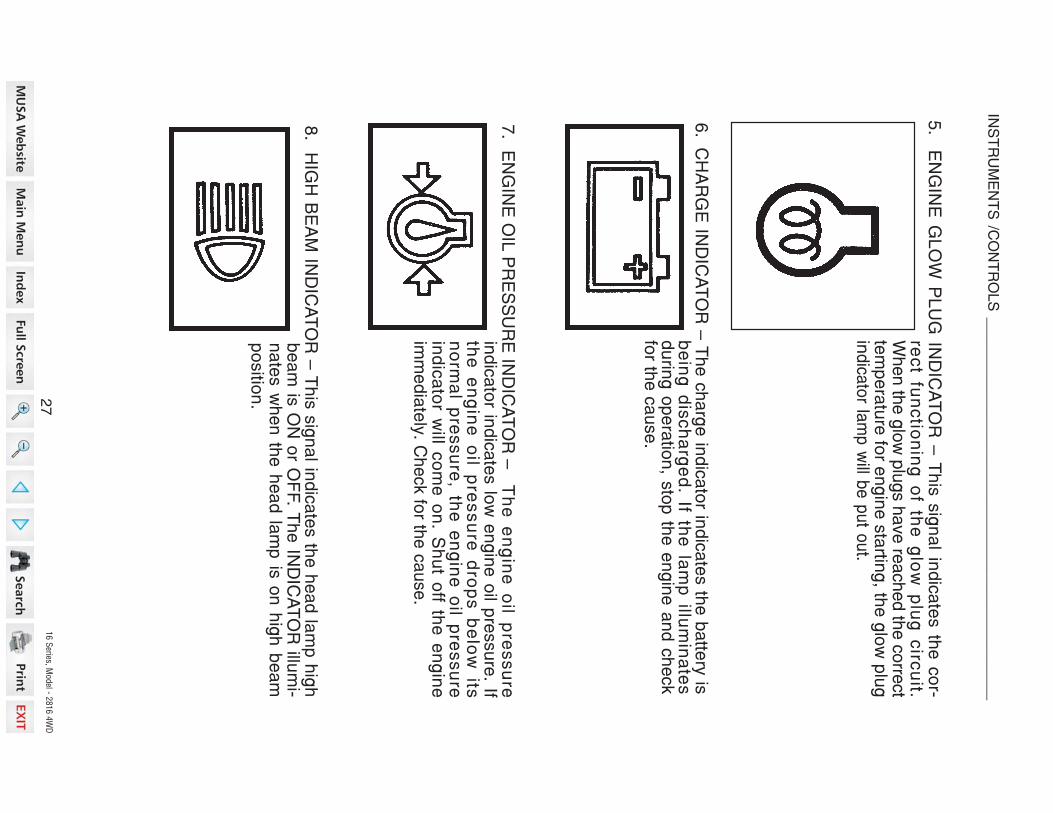
16 S
eries, Model - 2
816 4
WD
5. E
NG
INE
GL
OW
PL
UG
IND
ICA
TO
R –
Th
is s
ign
al in
dic
ate
s th
e c
or-
rec
t fun
ctio
nin
g o
f the
glo
w p
lug
circ
uit.
When th
e g
low
plu
gs h
ave re
ached th
e c
orre
ct
tem
pe
ratu
re fo
r en
gin
e s
tartin
g, th
e g
low
plu
gin
dica
tor la
mp
will b
e p
ut o
ut.
6.
CH
AR
GE
IND
ICA
TO
R –
Th
e c
ha
rge
ind
ica
tor in
dic
ate
s th
e b
atte
ry is
be
ing
dis
ch
arg
ed
. If the
lam
p illu
min
ate
sd
urin
g o
pe
ratio
n, s
top
the
en
gin
e a
nd
ch
eck
for th
e c
au
se
.
8.
HIG
H B
EA
M IN
DIC
AT
OR
– T
his
sig
na
l ind
ica
tes th
e h
ea
d la
mp
hig
hb
ea
m is
ON
or O
FF. T
he
IND
ICA
TO
R illu
mi-
na
tes w
he
n th
e h
ea
d la
mp
is o
n h
igh
be
am
po
sitio
n.
7. E
NG
INE
OIL
PR
ES
SU
RE
IND
ICA
TO
R –
Th
e e
ng
ine
oil p
res
su
rein
dic
ato
r ind
ica
tes lo
w e
ng
ine
oil p
ressu
re. If
the
e
ng
ine
o
il p
res
su
re d
rop
s b
elo
w its
no
rma
l pre
ssu
re, th
e e
ng
ine
oil p
ressu
rein
dic
ato
r will c
om
e o
n. S
hu
t off th
e e
ng
ine
imm
ed
iate
ly. C
he
ck fo
r the
ca
use.
27
INS
TR
UM
EN
TS
/C
ON
TR
OL
S _
__
__
__
__
__
__
__
__
__
__
__
__
__
__
__
__
__
__
__
__
__
__
_

16 S
eries, Model - 2
816 4
WD
1.
STA
RT
ER
KE
Y S
WIT
CH
— T
he
sta
rter k
ey s
witc
h c
an
be
rem
ove
dw
ith th
e s
witc
h in
the
OF
F p
ositio
n. F
ou
rp
ositio
n s
witc
h a
s fo
llow
s:
En
gin
e a
nd
all la
mp
s e
xce
pt
the
turn
sig
na
l an
d fla
sh
er
lam
ps a
re tu
rne
d o
ff.
Firs
t po
sitio
n c
lockw
ise
from
OF
F. In
this p
ositio
n (E
ngin
e n
ot
run
nin
g) e
ne
rgiz
es th
e g
low
plu
gs. T
he ch
arg
e in
dica
tor, g
low
plu
g in
dica
tor a
nd o
il pre
ssure
in-
dica
tor w
ill illum
inate
. T
he
fue
l ga
ug
e a
nd
tem
pe
ratu
re g
au
ge
will s
ho
w c
orre
ct v
alu
es.
OPERATING
CONTROLS
Contro
l Switc
hes
po
sitio
n–
(OF
F)
po
sitio
n–
(HE
AT
) & (O
N)
po
sitio
n –
(START)
Tu
rn th
e k
ey fu
lly c
lockw
ise
ag
ain
st th
e fo
rce
of th
esp
ring
in th
e s
witc
h. T
he
sta
rter m
oto
r will tu
rn th
ee
ng
ine
. Re
lea
se
the
ke
y im
me
dia
tely
wh
en
en
gin
esta
rts.
NO
TE
: To
pre
ve
nt o
pe
ratio
n b
y p
ers
on
s n
ot a
uth
oriz
ed
an
d th
ep
ossib
le d
isch
arg
e o
f the
ba
ttery, re
mo
ve
the
sta
rter k
ey w
he
n y
ou
lea
ve
the
tracto
r.
IMP
OR
TA
NT: D
o n
ot k
ee
p th
e s
tarte
r ke
y s
witc
h in
the
ON
po
sitio
n fo
ra
lon
g p
erio
d o
f time
wh
en
the
en
gin
e is
no
t op
era
ting
.2
8
INS
TR
UM
EN
TS
/C
ON
TR
OL
S _
__
__
__
__
__
__
__
__
__
__
__
__
__
__
__
__
__
__
__
__
__
__
_

16 S
eries, Model - 2
816 4
WD
2. E
NG
INE
SP
EE
D C
ON
TR
OL
LE
VE
R –
Mo
ve
the
en
gin
e s
pe
ed
co
ntro
l leve
r to th
e re
ar to
incre
ase
en
gin
esp
ee
d. M
ove
the
en
gin
e s
pe
ed
co
ntro
l leve
rfo
rwa
rd to
de
cre
ase
en
gin
e s
pe
ed
.
3. L
AM
P S
WIT
CH
– T
hre
e p
ositio
n s
witc
h a
s fo
llow
s:
–A
LL la
mp
s a
re O
FF. (T
urn
sig
na
l an
dfla
sh
er la
mp
s c
an
be
turn
ed
on
.)–
Firs
t po
sitio
n c
lockw
ise
illum
ina
tes
instru
me
nt p
an
el la
mp
an
d re
ar re
dla
mp
.–
Se
co
nd
po
sitio
n c
loc
kw
ise
illum
i-n
ate
s h
ea
dla
mp
s, in
stru
me
nt p
an
el
an
d re
ar re
d la
mp
.U
se
dim
me
r sw
itch
to d
im o
r brig
hte
nth
e h
ea
dla
mp
s.
4.
DIM
ME
R S
WIT
CH
– M
ove
the
dim
me
r sw
itch
to d
im o
r brig
hte
n th
eh
ea
d la
mp
s, w
he
n la
mp
sw
itch
is in
se
co
nd
po
sitio
n.
–M
ove
the
sw
itch
up
to b
righ
ten
the
he
ad
lam
ps.
–M
ov
e th
e s
witc
h d
ow
n to
dim
the
he
ad
lam
ps.
5. F
LA
SH
ER
CO
NT
RO
L B
UT
TO
N –
To
flash
the
Fla
sh
er L
am
ps w
he
n-
eve
r the
tracto
r is o
pe
rate
d o
r trave
ling
on
roa
ds.
Pu
sh
the
bu
tton
to e
ne
rgize
the
lam
ps.
29
INS
TR
UM
EN
TS
/C
ON
TR
OL
S _
__
__
__
__
__
__
__
__
__
__
__
__
__
__
__
__
__
__
__
__
__
__
_

16 S
eries, Model - 2
816 4
WD
6. T
UR
N S
IGN
AL S
WIT
CH
— T
o in
dic
ate
tha
t yo
u a
re g
oin
g to
turn
the
tracto
r to th
e R
IGH
T, m
ove
the
turn
sig
na
lsw
itch
up
. To
ind
ica
te th
at y
ou
are
go
ing
totu
rn th
e tra
cto
r to th
e L
EF
T, m
ove
the
turn
sig
na
l sw
itch
do
wn
. Ce
nte
r po
sitio
n is
OF
F.
7.
HO
RN
BU
TT
ON
(OP
TIO
NA
L) —
Pre
ss th
e b
utto
n to
en
erg
ize
the
ho
rn.
30
INS
TR
UM
EN
TS
/C
ON
TR
OL
S _
__
__
__
__
__
__
__
__
__
__
__
__
__
__
__
__
__
__
__
__
__
__
_

16 S
eries, Model - 2
816 4
WD
1.A
CC
ELE
RA
TO
R P
ED
AL
-U
se th
is pe
da
l wh
en
op
era
ting
the
tracto
r on
the
roa
d.
Pu
sh
the
p
ed
al
do
wn
to
in
crea
seengine speed.
NO
TE
:T
he
e
ng
ine
sp
ee
d
con
trol
leve
r mu
st be
set to
give
the
slow
est
engine speed when the throttle pedal is
used.
Control Levers and P
edals
(Gear D
rive)
31
INS
TR
UM
EN
TS
/C
ON
TR
OL
S _
__
__
__
__
__
__
__
__
__
__
__
__
__
__
__
__
__
__
__
__
__
__
_

16 S
eries, Model - 2
816 4
WD
2.
BR
AK
E P
ED
AL
S —
Th
e b
rake
pe
da
ls w
he
n lo
cke
d to
ge
the
r, pro
vid
es
bra
kin
g to
bo
th re
ar w
he
els
for s
top
-p
ing
the
tracto
r. Wh
en
the
bra
ke
pe
da
ls a
re u
nlo
cke
d, th
e p
ed
als
are
use
d fo
r ind
ivid
ua
l bra
kin
g o
f the
rea
r wh
ee
ls to
aid
in tu
rnin
g th
etra
cto
r in s
oft s
oil c
on
ditio
ns.
Pu
sh
the
RH
bra
ke
pe
da
l do
wn
tos
low
or s
top
the
RH
rea
r trac
tor
wh
ee
l, pu
sh
the
LH
bra
ke
pe
da
ld
ow
n to
slo
w o
r sto
p th
e L
H re
ar
wh
ee
l. Th
e tra
cto
r will tu
rn in
the
dire
ctio
n o
f the
wh
ee
l tha
t is s
low
ed
or s
top
pe
d.
3.
BR
AK
E P
ED
AL
LO
CK
– T
he
bra
ke
pe
da
l lock is
loca
ted
at th
e b
rake
pe
da
l arm
s a
nd
is u
se
d to
lock th
etw
o b
rake
pe
da
ls to
ge
the
r so
tha
tb
oth
bra
ke
s a
re a
pp
lied
.
CA
UT
ION
: Bra
ke
pe
da
ls m
us
t be
loc
ke
d to
ge
the
r for ro
ad
trav
el.
Th
is w
ill insu
re u
nifo
rm b
rake a
pp
licatio
n a
nd
maxim
um
sto
pp
ing
ab
ility.
WA
RN
ING
: E
xtra
weig
ht a
nd
bad
tractio
n c
on
ditio
ns s
uch
as m
ud
or
ice in
cre
ase y
ou
r sto
pp
ing
dis
tan
ce. R
em
em
ber th
at liq
uid
in th
etire
s, w
eig
hts
on
the m
ach
ine o
r wh
eels
, tan
ks fille
d w
ith fe
rtilizer,
herb
icid
es o
r insectic
ides - a
ll these a
dd
weig
ht a
nd
incre
ase th
ed
ista
nce y
ou
need
in w
hic
h to
sto
p.
32
INS
TR
UM
EN
TS
/C
ON
TR
OL
S _
__
__
__
__
__
__
__
__
__
__
__
__
__
__
__
__
__
__
__
__
__
__
_

16 S
eries, Model - 2
816 4
WD
(Gear D
rive)
4. P
AR
K B
RA
KE
LE
VE
R –
Th
e p
ark
bra
ke
mu
st b
e o
n to
pre
ve
nt
mo
ve
me
nt
of
the
tra
cto
r d
urin
gsta
tion
ary
po
we
r take
off w
ork
or
wh
en
the
tracto
r is p
ark
ed
. To
en
-g
ag
e th
e p
ark
bra
ke
, lock th
e b
rake
pe
da
ls to
ge
the
r, pu
sh
do
wn
on
the
bra
ke
pe
da
ls a
nd
mo
ve
the
pa
rkb
rake
leve
r do
wn
wa
rd. P
ush
the
bra
ke
pe
da
l do
wn
to re
lea
se
the
pa
rk b
rake
.
33
INS
TR
UM
EN
TS
/C
ON
TR
OL
S _
__
__
__
__
__
__
__
__
__
__
__
__
__
__
__
__
__
__
__
__
__
__
_

16 S
eries, Model - 2
816 4
WD
5.
CLU
TC
H P
ED
AL –
The c
lutc
h m
ust b
e d
isengaged w
hen s
tartin
g th
ee
ng
ine
, sto
pp
ing
the
tracto
r, sto
ring
the
tracto
r an
d o
pe
ratin
g th
efo
llow
ing
leve
rs,g
ea
r sh
ift leve
r, ran
ge
leve
r, rea
r PT
O le
ve
r, MID
PT
O L
ever, M
FD
lever c
reep le
ver.
5-1
.D
UA
L C
LU
TC
H
6.CLUTCH
LOC
K LATCH
– F
or lo
ng te
rm storage, lo
ck th
e clutch
pedal in
the disengaged positio
n. T
his
will p
revent th
e c
lutch
disc
from
sticking to
the engine flyw
heel.
Pedal h
as th
ree positio
ns as fo
llows:
1.Pedal c
ompletely
released –
Transmission and P
TO
engaged
2.Pedal p
artia
lly re
leased - T
ransmission disengaged, P
TO
en-
gaged
3.Pedal c
ompletely
depressed –
Transmission
and
PTO
disen-
gaged
34
INS
TR
UM
EN
TS
/C
ON
TR
OL
S _
__
__
__
__
__
__
__
__
__
__
__
__
__
__
__
__
__
__
__
__
__
__
_

16 S
eries, Model - 2
816 4
WD
Contro
l Levers
(Gear D
rive)
1.
GE
AR
SH
IFT
LE
VE
R —
The g
ear s
hift le
ver is
used to
shift th
etra
nsm
issio
n g
ears
into
revers
e o
r any o
fth
e th
ree fo
rward
speeds.
35
INS
TR
UM
EN
TS
/C
ON
TR
OL
S _
__
__
__
__
__
__
__
__
__
__
__
__
__
__
__
__
__
__
__
__
__
__
_

16 S
eries, Model - 2
816 4
WD
2.
RA
NG
E S
HIF
T L
EV
ER
— M
ove th
e ra
nge s
hift le
ver fo
rward
to p
lace
the tra
nsm
issio
n in
L ra
nge.
Mo
ve
the
leve
r to th
e re
ar-
wa
rd to
pla
ce
the
tran
s-
mis
sio
n in
M o
r H ra
ng
e.
Th
e c
en
ter
po
sitio
n b
e-
twe
en
M a
nd
L o
r H a
nd
Mp
lace
s th
e tra
nsm
issio
n in
N.
NO
TE
: Be
su
re th
e ra
ng
esh
ift leve
r is in
N (E
ng
ine
sta
rt) slo
t wh
en
sta
rting
the
en
gin
e.
3.REAR
PTO
CONTROL LEVER
– M
ove
the le
ver fo
rward
to engage
the R
EAR
PTO. M
ove th
elever re
arw
ard
to d
isen-
gage th
e R
ear P
TO.
NO
TE
: Be
su
re th
e R
ea
rP
TO
contro
l lever is
in O
FF
slo
t w
he
n
sta
rting
th
ee
ng
ine
.
4.
MID
PT
O C
ON
TR
OL
LE
VE
R (IF
EQ
UIP
PE
D) –
Mo
ve
the
leve
rfo
rwa
rd to
en
ga
ge
the
MID
PT
O. M
ove
the
leve
r rea
r-w
ard
to d
ise
ng
ag
e th
e M
idP
TO
.
NO
TE
:B
e s
ure
th
e M
idP
TO
contro
l lever is
in O
FF
slo
t w
he
n
sta
rting
th
ee
ng
ine
.
36
NO
TE
:
1.
The R
ear a
nd M
id P
TO
shaft c
an b
e o
pera
ted a
t the s
am
e tim
e.
2.
When n
ot u
sin
g th
e M
id P
TO
shaft, c
over th
e s
haft w
ith th
e M
id P
TO
co
ve
r.
INS
TR
UM
EN
TS
/C
ON
TR
OL
S _
__
__
__
__
__
__
__
__
__
__
__
__
__
__
__
__
__
__
__
__
__
__
_

16 S
eries, Model - 2
816 4
WD
5.
HIT
CH
CO
NT
RO
L L
EV
ER
– U
se
this
leve
r to c
on
trol th
e p
ositio
n o
fth
e h
itch
. Mo
ve
the
leve
r forw
ard
to lo
we
r the
hitc
h to
the
req
uire
dd
ep
th. M
ove
the
leve
r to th
e re
ar
to ra
ise
the
hitc
h to
the
req
uire
dh
eig
ht.
(Gear D
rive)
37
INS
TR
UM
EN
TS
/C
ON
TR
OL
S _
__
__
__
__
__
__
__
__
__
__
__
__
__
__
__
__
__
__
__
__
__
__
_

16 S
eries, Model - 2
816 4
WD
6. D
RA
FT
CO
NT
RO
L L
EV
ER
(IF E
QU
IPP
ED
) – U
se
dra
ft co
ntro
l with
so
il en
ga
gin
g im
ple
me
nts
to m
ain
-ta
in a
co
nsta
nt lo
ad
on
the
tracto
rth
rou
gh
va
riab
le s
oil c
on
ditio
ns. F
or
ligh
t loa
d o
pe
ratio
n, m
ove
the
leve
rto
the
rea
r. Fo
r he
avy lo
ad
op
era
-tio
n, m
ov
e th
e le
ve
r forw
ard
. To
sto
p th
e d
raft c
on
trol, m
ov
e th
ele
ve
r fully
forw
ard
.S
ee
Op
era
ting
with
Dra
ft Co
ntro
l inth
is m
an
ua
l for m
ore
info
rma
tion
.
7. R
EM
OT
E H
YD
RA
UL
IC C
ON
TR
OL L
EV
ER
, WIT
H F
LO
AT
PO
SIT
ION
(IF E
QU
IPP
ED
) – A
do
ub
le a
ctin
gre
mo
te c
on
trol v
alv
e is
ava
ilab
le fo
ryo
ur tra
cto
r. Th
e re
mo
te h
yd
rau
licc
on
trol le
ve
r wh
ich
op
era
tes
the
rem
ote
co
ntro
l va
lve
is lo
ca
ted
on
the
RH
sid
e fe
nd
er.
Se
e R
em
ote
Hyd
rau
lic C
on
trol in
this
ma
nu
al fo
r mo
re in
form
atio
n.
38
INS
TR
UM
EN
TS
/C
ON
TR
OL
S _
__
__
__
__
__
__
__
__
__
__
__
__
__
__
__
__
__
__
__
__
__
__
_

16 S
eries, Model - 2
816 4
WD
(Gear D
rive)
1.
DIF
FE
RE
NT
IAL
LO
CK
PE
DA
L –
Pu
sh
the
pe
da
l do
wn
to e
ng
ag
e th
ed
iffere
ntia
l lock. A
sp
ring
insid
e th
e d
iffere
ntia
l lock w
ill pu
sh
it ou
t of
en
ga
ge
me
nt w
he
n p
ed
al is re
lea
sed
.
GE
AR
DR
IVE
39
INS
TR
UM
EN
TS
/C
ON
TR
OL
S _
__
__
__
__
__
__
__
__
__
__
__
__
__
__
__
__
__
__
__
__
__
__
_

16 S
eries, Model - 2
816 4
WD
NO
TE
: W
he
n e
ng
ag
ing
the
diffe
ren
tial lo
ck, p
ush
the
clu
tch
pe
da
ld
ow
n o
r brin
g s
pe
ed
ratio
co
ntro
l pe
da
l to N
eu
tral, to
sto
p th
e w
he
els
that a
re ro
tatin
g, th
en p
ush th
e d
iffere
ntia
l lock p
edal. D
o n
ot o
pera
te th
ediffe
rentia
l lock p
edal w
hile
the w
heels
are
rota
ting.
2. M
FD
CO
NT
RO
L L
EV
ER
– T
o e
ng
ag
e th
e M
FD
(Me
ch
an
ica
l Fro
nt
Driv
e),
mo
ve
th
e
MF
Dc
on
trol
lev
er
do
wn
wa
rd.
Mo
ve
th
e le
ve
r u
pw
ard
to
dis
en
ga
ge
MF
D (d
rive
to th
ere
ar w
heels
only
).
IMP
OR
TA
NT:
Th
e
clu
tch
pedal m
ust b
e p
ushed d
ow
nto
opera
te th
e M
FD
lever.
3.
HY
DR
AU
LIC
FL
OW
CO
NT
RO
L K
NO
B –
Use
the
hyd
rau
lic flo
wco
ntro
l kn
ob
to a
dju
st th
e h
itch
low
erin
g s
pe
ed
. Ad
just th
e lo
we
ring
sp
ee
d to
pro
vid
e s
mo
oth
op
era
tion
of th
e h
itch
with
the
imp
lem
en
tbein
g u
sed. T
urn
the k
nob fu
lly c
lockw
ise to
lock th
e h
itch in
positio
n.
Se
e H
itch
Lo
we
ring
Sp
ee
d A
dju
stm
en
t in th
is m
an
ua
l for m
ore
in-
form
atio
n.
Do
no
t driv
e o
n ro
ad
s, o
r at h
igh
sp
ee
d a
ny
wh
ere
, with
the
diffe
ren
tial lo
ck e
ng
ag
ed
. Diffic
ult s
teerin
g w
ill occu
r, an
d c
an
re-
su
lt in a
n a
ccid
en
t. In fie
ld o
pera
tion
, use th
e d
iffere
ntia
l lock fo
rtra
ctio
n im
pro
vem
en
t, bu
t rele
ase fo
r turn
ing
at ro
w e
nd
s.
M116
40
INS
TR
UM
EN
TS
/C
ON
TR
OL
S _
__
__
__
__
__
__
__
__
__
__
__
__
__
__
__
__
__
__
__
__
__
__
_

16 S
eries, Model - 2
816 4
WD
SE
AT
AD
JU
ST
ING
LE
VE
R
OPERATORS
SEAT
The
seat c
an
be
adjusted
in 5
fore
/aft p
ositio
ns b
y th
e le
ver lo
cated
under th
e R
H side
of th
e seat.
The
seat is a
djusta
ble
fore
and
aft b
y movin
g a
leve
r.
1.
Move
the
lever u
pward.
2.
Move
the
seat re
arw
ard
or fo
rward
to th
e re
quire
d p
ositio
n th
en
re-
lease
the
lever.
3.
Push
the
seat re
arw
ard
to m
ake
sure
that th
e lo
ck is engaged.
STEERIN
G C
OLUMN
TILT
The
steerin
g wheel angle
can
be
adjusted
in th
ree
positio
ns by th
e le
ver
located
under th
e steerin
g column.
To
adjust th
e p
ositio
n o
f the
steerin
gwheel, u
se
f ollo
wing
procedure.
1.
Move th
e le
ver fu
lly downward
todisengage
the
latch
fro
m the
column.
2.
Move
the
steerin
g w
heel re
arw
ard
or fo
rward
to th
e re
quire
d positio
n,
then
return
the
lever u
pward
to lo
ck
the
steerin
g column.
3.
Make
sure
that the
lock
is
en-
gaged.
ST
EE
RIN
G
CO
LU
MN
T
ILT
LE
VE
R
41
INS
TR
UM
EN
TS
/C
ON
TR
OL
S _
__
__
__
__
__
__
__
__
__
__
__
__
__
__
__
__
__
__
__
__
__
__
_

16 S
eries, Model - 2
816 4
WD
BEFORE
STARTIN
G T
HE
ENGIN
E
Before
startin
g your tra
ctor fo
r the
first tim
e and
before
each
operatin
gperio
d afte
r that, m
ake
these
checks:
1.Make
sure
all p
ersons th
at o
perate
or d
o m
aintenance
on
the
tractor
understand
that c
lean
fuel is
importa
nt.
2.Check all lu
bric
atio
n fittin
gs fo
r grease
as given
in th
e Lubric
atio
nChart.
3.Check th
e oil le
vel in
the
engine
crankcase. C
heck th
e flu
id le
vel in
the
transmission.
4.Check th
at th
e tra
ctor fu
el ta
nk is
filled
with
clean
fuel th
at h
as th
especific
atio
ns given
in th
is m
anual.
NO
TE
: Cle
an
aro
un
d th
e fu
el ta
nk c
ap
be
fore
yo
u re
mo
ve
the
ca
p.
5.
Ch
eck th
e fu
el s
yste
m, c
oo
ling
syste
m a
nd
en
gin
e o
il pa
n fo
r lea
ks.
6.
Ch
eck th
e fa
n b
elt is
ad
juste
d c
orre
ctly.
7.
Re
mo
ve
an
y w
ate
r or s
ed
ime
nt fro
m th
e fu
el filte
r cu
p.
8.
Ch
eck th
e a
ir pre
ssu
re o
f the
tires.
9.
Ma
ke
su
re th
e P
TO
sa
fety g
ua
rd is in
stalle
d.
10
.C
he
ck th
e c
oo
lan
t leve
l in th
e ra
dia
tor a
nd
rese
rvo
ir bo
ttle. A
dd
wa
ter a
nd
eth
yle
ne
gly
co
l co
ola
nt a
s n
ee
de
d.
42
OP
ER
AT
ING
INS
TR
UC
TIO
NS
_
___________________________________________

16 S
eries, Model - 2
816 4
WD
RUN-IN
PROCEDURE
If run-in
instru
ctio
ns fo
r a new
engine
are
not fo
llowed, y
ou
can
cause
damage
to piston
rings and
cylin
der w
alls.
LOAD
Never o
perate
an
engine
immediately
under fu
ll load. A
llow
the
engine
towarm
up
before
operatin
g it a
t full lo
ad. R
un-in
the
engine
carefully
as
shown
in th
e ta
ble.
NO
LO
AD
Do
no
t run
the
en
gin
e a
t idle
sp
ee
d. W
he
n n
ot o
pe
ratin
g th
e e
ng
ine
with
a lo
ad
, yo
u c
an
ke
ep
the
co
rrect e
ng
ine
op
era
ting
tem
pe
ratu
re if y
ou
run
the
en
gin
e a
t ap
pro
xim
ate
ly 1
50
0 R
PM
.
RE
AR
WH
EE
L B
OLT
SA
fter th
e firs
t 10
ho
urs
of o
pe
ratio
n, c
he
ck th
e re
ar w
he
el b
olts
. Tig
hte
na
ll wh
ee
l bo
lts to
the
torq
ue
giv
en
in th
e W
he
el M
ou
ntin
g T
orq
ue
s in
this
ma
nu
al.
FR
ON
T W
HE
EL B
OLT
SA
fter th
e firs
t 10
ho
urs
of o
pe
ratio
n, c
he
ck th
e fro
nt w
he
el b
olts
. Tig
hte
nth
e b
olts
to th
e to
rqu
es s
ho
wn
in th
e W
he
el M
ou
ntin
g T
orq
ue
s in
this
ma
nu
al.
FR
ON
T F
RA
ME
BO
LT
SA
fter th
e firs
t 10
ho
urs
of o
pe
ratio
n, c
he
ck th
e fro
nt fra
me
bo
lts. T
igh
ten
the
bo
lts to
the
torq
ue
sh
ow
n b
elo
w.
Fro
nt F
ram
e M
ou
ntin
g T
orq
ue
sS
ide
(M1
2x3
5), 8
Bo
lts (4
LH
an
d 4
RH
) ... 83
to 9
3 N
m (6
1 to
69
lb ft)
LO
WE
R L
INK
BR
AC
KE
T B
OLT
SA
fter th
e firs
t 10
ho
urs
of o
pe
ratio
n, c
he
ck th
e lo
we
r link b
racke
t bo
lts.
Tig
hte
n th
e b
olts
to th
e c
orre
ct tig
hte
nin
g to
rqu
e 3
9 to
44
Nm
(29
to 3
3Ib
ft).
Fu
ll load
go
vern
ed
sp
eed
with
occasio
nal
sh
ort p
erio
ds o
f ligh
ter
loa
d.
Fu
lly
ad
va
nc
ed
1st H
ou
r
2n
d
Th
ro
ug
h
5th
Ho
ur
Fu
lly
ad
va
nc
ed
Pe
rio
d
En
gin
e S
peed
Co
ntr
ol L
ever
Po
sitio
n
Lo
ad
Main
tain
en
gin
e s
peed
100 R
PM
ab
ove fu
ll load
go
vern
ed
sp
eed
.
43
OP
ER
AT
ING
INS
TR
UC
TIO
NS
_
___________________________________________

16 S
eries, Model - 2
816 4
WD
En
gin
e c
an
sta
rt with
tran
sm
issio
n in
gear w
hen
neu
tral o
r safe
tysta
rt sw
itch
is b
y-p
assed
:1
.D
o n
ot c
on
nect a
cro
ss te
rmin
als
on
sta
rter.
2.
Atta
ch
a b
oo
ste
r batte
ry b
y c
on
nectin
g th
e p
ositiv
e te
rmin
al o
f the
bo
oste
r batte
ry to
the “
po
sitiv
e te
rmin
al”
pro
vid
ed
or to
the p
o-
sitiv
e te
rmin
al o
f the m
ach
ine b
atte
ry. C
on
nect th
e n
eg
ativ
e te
r-m
inal o
f the b
oo
ste
r batte
ry to
the “
neg
ativ
e te
rmin
al”
pro
vid
ed
or
to th
e c
hassis
of th
e m
ach
ine.
Th
en
use re
co
mm
en
ded
sta
rting
pro
ced
ure
s fro
m o
pera
tors
seat.
3.
Wh
en
necessary
, rep
air e
lectric
al s
yste
m c
om
po
nen
ts p
rom
ptly
so
that “
jum
p s
tartin
g” w
ill no
t be a
ttem
pte
d.
Mach
ine ru
n-a
way c
an
cau
se in
jury
or d
eath
to o
pera
tor a
nd
bysta
n-
de
rs.
Ma
ke
su
re th
e fu
el s
hu
t-off v
alv
eis
op
en
. Th
e v
alv
e is
loca
ted
at
the
bo
ttom
RH
sid
e o
f the
fue
lta
nk.
NORMAL S
TARTIN
G P
ROCEDURE
IMP
OR
TA
NT:
It is v
ery
imp
orta
nt th
at e
no
ug
h lu
bric
an
t rea
ch
es th
een
gin
e p
arts
be
fore
op
era
ting
the
en
gin
e a
t rate
d s
pe
ed
.
Op
era
te c
on
trols
on
ly w
he
n s
ea
ted
in th
e o
pe
rato
rs s
ea
t.
Be
fore
sta
rting
the
en
gin
e, b
e s
ure
all o
pe
ratin
g c
on
trols
are
inn
eu
tral o
r pa
rk lo
ck
po
sitio
n. T
his
will e
limin
ate
ac
cid
en
tal
mo
ve
me
nt o
f the
ma
ch
ine
or s
tart u
p o
f po
we
r driv
en
eq
uip
me
nt.
Pu
t the
ge
ar s
hift le
ve
r in th
eN
eu
tral p
ositio
n (G
ea
r Driv
e)
M137
ST
EP
1
OP
EN
FU
EL
S
HU
T-O
FF
V
ALV
ES
TE
P 2
NE
UT
RA
L P
OS
ITIO
N
M106D
M107C
44
OP
ER
AT
ING
INS
TR
UC
TIO
NS
_
___________________________________________

16 S
eries, Model - 2
816 4
WD
Tu
rn th
e s
tarte
r ke
y s
witc
h to
the
he
at &
ON
po
sitio
n.
Wa
it un
til the
glo
w p
lug
ind
ica
tor
lam
p is
pu
t ou
t.(A
pp
roxim
ate
ly 1
to 3
se
co
nd
s.)
Pu
t the
ran
ge
sh
ift leve
r in th
e N
(En
gin
e s
tart) s
lot.
Pu
t the
RE
AR
PT
O a
nd
MID
PT
O c
on
trol le
ve
rs in
the
OF
F(E
ng
ine
sta
rt) slo
t.
ST
EP
2
ST
EP
3S
TE
P 5
OF
F P
OS
ITIO
N
N S
LO
TS
HE
AT
Pu
t the
en
gin
e s
pe
ed
co
ntro
lle
ve
r at th
e lo
w id
le p
ositio
n.
ST
EP
4
ST
OP
45
OP
ER
AT
ING
INS
TR
UC
TIO
NS
_
___________________________________________

16 S
eries, Model - 2
816 4
WD
Tu
rn k
ey s
witc
h to
sta
rt po
sitio
nu
ntil e
ng
ine
sta
rts, b
ut n
o m
ore
tha
n 1
0 s
eco
nd
s, th
en
rele
ase
the
k
ey.
Ru
n
en
gin
e
for
two
min
ute
s a
t 15
00
RP
M.
NO
TE
: If the
oil p
ressu
re in
dic
ato
r sta
ys o
n a
fter th
e e
ng
ine
sta
rts, s
top
the
en
gin
e a
nd
ch
eck th
e o
il leve
l in th
e c
ran
kca
se
. Ad
d o
il if ne
ce
ssa
ry.S
tart th
e e
ng
ine
, if the
ind
ica
tor is
still o
n, d
o n
ot o
pe
rate
the
en
gin
e.
Op
era
ting
the
en
gin
e w
itho
ut o
il pre
ssu
re w
ill da
ma
ge
en
gin
e b
ea
ring
san
d o
the
r en
gin
e p
arts
. Se
e y
ou
r de
ale
r.
IMP
OR
TA
NT:
1.
If hig
h id
le p
ositio
n is
use
d fo
r sta
rting
, ad
just th
e e
ng
ine
sp
ee
dco
ntro
l leve
r to o
bta
in a
bo
ut 1
50
0 R
PM
as s
oo
n a
s th
e e
ng
ine
sta
rts.
2.
If the
en
gin
e s
tarts
an
d th
en
sto
ps, w
ait fo
r the
sta
rting
mo
tor to
sto
ptu
rnin
g b
efo
re y
ou
turn
the
ke
y s
witc
h to
STA
RT
po
sitio
n a
ga
in.
ST
EP
7
ST
EP
6
CL
UT
CH
PE
DA
L
Pu
sh
the
clu
tch
pe
da
l do
wn
.
ST
EP
8
Wh
en
the
en
gin
e s
tarts
, ch
eck
the
oil p
res
su
re in
dic
ato
r an
dch
arg
e in
dic
ato
r.If th
e in
dic
ato
rs s
tay
on
, sto
pth
e e
ng
ine
an
d fin
d o
ut w
ha
t isw
ron
g.
STA
RT
46
OP
ER
AT
ING
INS
TR
UC
TIO
NS
_
___________________________________________

16 S
eries, Model - 2
816 4
WD
3.
Do
no
t use
the
sta
rter m
oto
r for m
ore
tha
n 1
0 s
eco
nd
s w
itho
ut
sto
pp
ing
. Wa
it on
e m
inu
te b
etw
ee
n s
tarts
so
the
sta
rter m
oto
r ca
nco
ol.
4.
If the
en
gin
e s
top
s w
he
n o
pe
ratin
g w
ith a
loa
d, im
me
dia
tely
sta
rt the
en
gin
e a
ga
in to
pre
ve
nt o
ve
rhe
atin
g c
au
se
d b
y s
top
pin
g th
e flo
w o
fo
il for c
oo
ling
an
d lu
bric
atio
n.
5.
If the
ch
arg
e in
dic
ato
r co
me
s o
n d
urin
g o
pe
ratio
n, d
ete
rmin
e a
nd
co
rrect th
e c
au
se
to a
vo
id c
om
ple
te d
isch
arg
e o
f the
ba
ttery
an
dp
ossib
le d
am
ag
e to
oth
er c
om
po
ne
nts
of th
e e
lectric
al s
yste
m. S
ee
yo
ur D
ea
ler.
6.
If the
co
ola
nt te
mp
era
ture
ind
ica
tor c
om
es o
n, re
mo
ve
the
loa
d a
nd
allo
w th
e e
ng
ine
to ru
n a
t 15
00
rpm
un
til the
ind
ica
tor g
oe
s o
ut. If th
ein
dic
ato
r do
es n
ot g
o o
ut w
ithin
on
e m
inu
te, s
top
the
en
gin
e a
nd
de
term
ine
the
ca
use
.
47
OP
ER
AT
ING
INS
TR
UC
TIO
NS
_
___________________________________________

16 S
eries, Model - 2
816 4
WD
ST
EP
1S
TE
P 3
OF
F
ST
EP
2
RE
AR
P
TO
LE
VE
R
IMP
OR
TA
NT:
W
he
n s
top
pin
g th
e e
ng
ine
afte
r op
era
ting
un
de
r he
avy
loa
d, ru
n th
e e
ng
ine
at 1
50
0 R
PM
for a
sh
ort p
erio
d o
f time
. Th
is w
illa
llow
the
en
gin
e te
mp
era
ture
to d
ecre
ase
gra
du
ally.
Pu
t the
RE
AR
PT
O c
on
trol le
ve
r,M
ID P
TO
co
ntro
l leve
r an
d th
era
ng
e s
hift le
ve
r in th
e O
FF
or N
(ne
utra
l) po
sitio
n.
Mo
ve
the
en
gin
e s
pe
ed
co
ntro
lle
ve
r to ru
n e
ng
ine
at id
le s
pe
ed
for
thre
e
to
five
m
inu
tes
to
de
cre
as
e
the
te
mp
era
ture
o
fe
ng
ine
.
Tu
rn th
e k
ey s
witc
h to
OF
F p
osi-
ti on
. Re
mo
ve
the
ke
y.
STOPPIN
G T
HE
ENGIN
E
MID
P
TO
LE
VE
R
48
OP
ER
AT
ING
INS
TR
UC
TIO
NS
_
___________________________________________
ST
OP

16 S
eries, Model - 2
816 4
WD
COLD
TEMPERATURE
OPERATIO
N
To
sta
rt an
d o
pe
rate
yo
ur tra
cto
r du
ring
co
ld a
mb
ien
t tem
pe
ratu
res, u
se
the
se
pro
ce
du
res :
1.
BA
TT
ER
Y –
Mu
st h
ave
a fu
ll ch
arg
e.
2.
FU
EL —
Mu
st b
e c
lea
n a
nd
with
no
wa
ter. S
ee
fue
l Sp
ecific
atio
ns in
this
ma
nu
al.
3.
EN
GIN
E O
IL –
Mu
st h
ave
the
co
rrect v
iso
city
for th
e a
mb
ien
t tem
-p
era
ture
ran
ge
.
4. T
RA
NS
MIS
SIO
N H
YD
RA
UL
IC F
LU
ID –
Use
Hyd
rau
lic Tra
nsm
ission
fluid
.
5.
CO
OL
ING
SY
ST
EM
– M
ust h
ave
eth
yle
ne
gly
co
l so
lutio
n fo
r pro
tec-
tion
.
6.
TIR
ES
– If th
ere
is liq
uid
in th
e tire
s, th
e tire
s m
ust h
ave
pro
tectio
na
ga
inst te
mp
era
ture
s b
elo
w 0
o C
(32
o F
). Se
e y
ou
r De
ale
r.
7.
ST
OP
PIN
G T
HE
EN
GIN
E –
Ru
n th
e e
ng
ine
at id
le s
pe
ed
for a
sh
ort
pe
riod
of tim
e to
pe
rmit th
e e
ng
ine
tem
pe
ratu
re to
de
cre
ase
be
fore
sto
pp
ing
.
8.
CO
ND
EN
SA
TIO
N IN
FU
EL T
AN
K –
To
pre
ve
nt c
on
de
nsa
tion
in th
efu
el ta
nk a
nd
wa
ter e
nte
ring
the
fue
l syste
m, fill th
e fu
el ta
nk a
fter
ea
ch
op
era
ting
da
y.
9.
FU
EL F
ILT
ER
CU
P –
Du
ring
co
ld a
mb
ien
t tem
pe
ratu
res, m
ake
su
reyou
rem
ove
wa
ter fro
m th
e fu
el filte
r cu
p e
ach
da
y.
NO
TE
: Do
no
t use
eth
er a
s a
co
ld te
mp
era
ture
sta
rting
aid
.
IMP
OR
TA
NT:
To
sta
rt en
gin
e d
urin
g c
old
am
bie
nt te
mp
era
ture
s, p
ut th
e
en
gin
e co
ntro
l leve
l at th
e lo
w id
le p
ositio
n.
Afte
r sta
rting
the
en
gin
e, ru
n a
t 15
00
rpm
for a
pp
roxim
ate
ly 5
min
ute
s to
wa
rm th
e
en
gin
e.
49
OP
ER
AT
ING
INS
TR
UC
TIO
NS
_
___________________________________________

16 S
eries, Model - 2
816 4
WD
IMP
OR
TA
NT: D
urin
g c
old
am
bie
nt te
mp
era
ture
s, n
eve
r run
the
en
gin
eat lo
w id
le s
peed fo
r long p
erio
ds o
f time.
Durin
g c
old
am
bie
nt te
mpera
ture
s, th
e e
ngin
e w
ill not h
eat to
or k
eep th
era
ted o
pera
ting
tem
pera
ture
at s
low
engin
e s
peeds. S
low
engin
e s
peeds
in c
old
tem
pera
ture
s c
an c
ause d
am
age to
the e
ngin
e. U
se th
e fo
llow
ing
pro
cedure
s to
warm
the e
ngin
e a
nd tra
nsm
issio
n flu
ids, a
nd to
keep th
ecorre
ct o
pera
ting te
mpera
ture
s.
1. W
AR
MIN
G T
HE
EN
GIN
E A
ND
TR
AN
SM
ISS
ION
.
A.
To
he
at
the
tran
sm
issio
n flu
id to
op
era
ting
tem
pe
ratu
re, ru
n th
eengin
e a
t 1500 R
PM
for a
ppro
xim
ate
ly fiv
e m
inute
s.
IMP
OR
TA
NT:
Op
era
ting
the
tracto
r with
co
ld tra
nsm
issio
n flu
id c
an
cause ro
ugh tra
ctor o
pera
tion w
ith p
ossib
le in
jury to
the o
pera
tor.
2. K
EE
P E
NG
INE
AT
CO
RR
EC
T O
PE
RA
TIN
G T
EM
PE
RA
TU
RE
.
A.
Never ru
n th
e e
ngin
e b
elo
w 1
500 R
PM
.B
.P
ut a
cover in
front o
f the g
rille to
contro
l the a
mount o
f air g
oin
gth
rough th
e ra
dia
tor.
3. S
TO
PP
ING
TH
E E
NG
INE
.
A.
Run th
e e
ngin
e a
t slo
w s
peed fo
r a s
hort p
erio
d o
f time. T
his
will
pe
rmit th
e e
ng
ine
tem
pe
ratu
re to
de
cre
ase
gra
du
ally
be
fore
sto
p-
pin
g th
e e
ngin
e.
50
OP
ER
AT
ING
INS
TR
UC
TIO
NS
_
___________________________________________

16 S
eries, Model - 2
816 4
WD
Wh
en
tow
ing
a tra
cto
r, follo
w th
ese
rule
s:
1.
Ne
ve
r pu
ll the
tracto
r faste
r tha
n a
gro
un
d s
pe
ed
of 1
6 K
m/h
(10
MP
H).
2.
Ma
ke su
re a
ll con
trols a
re in
the
ne
utra
l or O
FF
po
sition
.
3.
Be
ca
use
of a
po
ssib
le lo
ss o
f ste
erin
g a
nd
bra
ke
s w
he
n th
e tra
cto
re
ng
ine
is n
ot ru
nn
ing
, use
on
ly a
rigid
tow
ing
ba
r an
d s
afe
ty c
ha
ins to
pu
ll the
tracto
r.
TOWING
Make s
ure
that th
e w
eig
ht o
f a tra
iled
veh
icle
that is
no
t eq
uip
ped
with
bra
ke
s, N
EV
ER
EX
CE
ED
S th
e w
eig
ht o
f the
ma
ch
ine
tha
t is
tow
ing
the
ve
hic
le. S
top
pin
g d
ista
nc
e in
cre
as
es
with
inc
rea
sin
g
sp
eed
as th
e w
eig
ht o
f the to
wed
load
incre
ases, e
sp
ecia
lly o
n h
ills
an
d s
lop
es.
Wh
en
yo
u tra
nsp
ort th
e tra
cto
r by tru
ck o
r rail, fo
llow
the
se
rule
s:
1.
Ho
ld th
e tra
cto
r with
tie d
ow
ns a
nd
blo
ck th
e w
he
els
.
2.
Hyd
rosta
tic D
rive
: Mo
ve
the
Sp
ee
d L
ock le
ve
r to O
FF
po
sitio
n a
nd
pu
t the
ran
ge
sh
ift leve
r in th
e L
po
sitio
n.
3.
Lo
ck th
e b
rake
pe
da
ls to
ge
the
r, pu
sh
the
bra
ke
pe
da
ls d
ow
n a
nd
mo
ve
the
pa
rk b
rake
leve
r up
to e
ng
ag
e th
e p
ark
bra
ke
.
HOW
TO
TRANSPORT
TRACTOR
M111A
51
OP
ER
AT
ING
INS
TR
UC
TIO
NS
_
___________________________________________

16 S
eries, Model - 2
816 4
WD
GEAR
DRIVE
TRANSMISSIO
N
Th
e g
ea
r driv
e tra
nsm
issio
n h
as a
thre
e fo
rwa
rd a
nd
on
e re
ve
rse
ge
ar
se
ctio
n a
nd
a th
ree
-sp
ee
d ra
ng
e s
ectio
n. T
his
arra
ng
em
en
t giv
es 9
forw
ard
and 3
revers
e s
peeds.
Transmission O
peratio
n
1.
The tra
cto
r is e
quip
ped w
ith d
ual c
lutc
h. T
he tra
cto
r movem
ent s
tops
by p
ressin
g th
e c
lutc
h p
edal h
alfw
ay. P
ressin
g th
e p
edal fu
lly s
tops
the P
TO
shafts
.2
.P
ush th
e c
lutc
h p
edal a
nd s
top th
e tra
cto
r. Move th
e g
ear s
hift le
ver
to th
e g
ear n
eeded.
3.
Mo
ve
the
ran
ge
sh
ift leve
r to th
e p
ositio
n n
ee
de
d, H
, M o
r L, (T
he
tracto
r mu
st b
e s
top
pe
d b
efo
re th
e ra
ng
e le
ve
r is o
pe
rate
d.)
4.
Rele
ase th
e c
lutc
h p
edal s
low
ly.5
.T
he g
ear s
hift le
ver c
an b
e s
hifte
d in
to a
ny ra
nge w
hen tra
velin
g. T
odo th
is, p
ush th
e c
lutc
h p
edal h
alf w
ay a
nd m
ove th
e g
ear s
hift le
ver
to th
e p
ositio
n n
eeded.
IMPORTANT:
Be
fore
se
lectin
g a
ne
w ra
ng
e, p
ush
the
clu
tch
pe
da
lh
alfw
ay a
nd
sto
p th
e tra
cto
r. Do
no
t ch
an
ge
ran
ge
wh
en
the
tracto
r ism
ovin
g.
NOTE:
When s
hiftin
g fro
m th
ird to
anoth
er ra
nge, b
e c
are
ful n
ot to
run
the e
ngin
e a
t more
than 2
700 R
PM
.52
OP
ER
AT
ING
INS
TR
UC
TIO
NS
_
___________________________________________

16 S
eries, Model - 2
816 4
WD
DIFFERENTIAL LOCK
GE
AR
DR
IVE
RIG
HT
SID
E o
f the tra
nsm
issio
n
Yo
ur tra
cto
r ha
s a
diffe
ren
tial lo
ck th
at w
ill ma
ke
bo
th re
ar w
he
els
turn
at
the
sa
me
sp
ee
d. T
he
diffe
ren
tial lo
ck p
reve
nts
loss o
f po
we
r wh
en
on
ew
he
el d
oe
s n
ot h
ave
tractio
n b
ut th
e o
the
r wh
ee
l do
es h
ave
tractio
n. It
als
o p
rovid
es a
stra
igh
t in lin
e s
tee
ring
aid
wh
en
op
en
ing
up
the
field
an
dto
co
ntro
l imp
lem
en
t ove
rlap
.
TO
EN
GA
GE
TH
E D
IFF
ER
EN
TIA
L L
OC
K:
De
pre
ss a
nd
ho
ld th
e d
iffere
ntia
l lock p
ed
al d
ow
n.
IMP
OR
TA
NT
: Do
no
t en
ga
ge
the
diffe
ren
tial lo
ck w
hile
on
e re
ar w
he
el
is ro
tatin
g a
nd
the
oth
er re
ar w
he
el is
sto
pp
ed
. Alw
ays s
top
the
wh
ee
lth
at is
rota
ting a
nd th
en e
ngage th
e d
iffere
ntia
l lock.
IMP
OR
TA
NT: W
he
n y
ou
en
ga
ge
or d
ise
ng
ag
e th
e d
iffere
ntia
l lock, th
efro
nt w
he
els
mu
st b
e in
the
stra
igh
t forw
ard
po
sitio
n. B
efo
re tu
rnin
g th
etra
cto
r, dis
engage th
e d
iffere
ntia
l lock.
TO
DIS
EN
GA
GE
TH
E D
IFF
ER
EN
TIA
L L
OC
K:
Th
e d
iffere
ntia
l lock w
ill dis
en
ga
ge
wh
en
the
diffe
ren
tial lo
ck p
ed
al is
rele
ase
d. If th
e d
iffere
ntia
l lock d
oe
s n
ot d
ise
ng
ag
e e
asily, p
ush
do
wn
on
eith
er b
rake
pe
da
l insta
nta
ne
ou
sly.
DIF
FE
RE
NT
IAL L
OC
K P
ED
AL
53
OP
ER
AT
ING
INS
TR
UC
TIO
NS
_
___________________________________________
Do
no
t driv
e o
n ro
ad
s, o
r at h
igh
sp
ee
d a
ny
wh
ere
, with
the
diffe
ren
tial lo
ck
en
ga
ge
d. D
ifficu
lt ste
erin
g w
ill oc
cu
r, an
d c
an
res
ult
in a
n a
cc
ide
nt. In
field
op
era
tion
, us
e th
e d
iffere
ntia
l loc
k fo
r trac
tion
imp
rov
em
en
t, bu
t rele
as
e fo
r turn
ing
at ro
w e
nd
s.
M11
6

16 S
eries, Model - 2
816 4
WD
POWER
TAKEOFF
(PTO)
PT
O d
riven
mach
inery
can
cau
se s
erio
us in
jury
or d
eath
, usu
ally
du
e
to w
rap
ped
clo
thin
g. W
hen
req
uire
d b
y th
e jo
b to
be in
the d
rive s
haft
are
a, s
tay c
lear o
f rota
ting
parts
. Befo
re w
ork
ing
on
the d
rive s
haft,
or s
erv
icin
g o
r cle
arin
g th
e d
riven
mach
ine, w
here
ap
plic
ab
le o
n th
is
tracto
r, pu
t the P
TO
clu
tch
lever in
the D
ISE
NG
AG
E p
ositio
n, th
e P
TO
lev
er in
the
NE
UT
RA
L o
r OF
F, a
nd
ST
OP
the
en
gin
e M
12
5A
Rear P
TO
Th
e re
ar P
TO
is a
54
0 R
PM
with
a 3
4.9
mm
(1 3
/8 in
ch
) dia
me
ter 6
sp
line
ou
tpu
t sh
aft.
EN
GA
GE
TH
E R
EA
R P
TO
AS
FO
LL
OW
S:
1.
Pu
sh
the
clu
tch
pe
da
l fully.
2.
Mo
ve
the
PT
O c
on
trol le
ve
rfo
rwa
rd o
r rea
rwa
rd.
3.
Re
lea
se
the
clu
tch
pe
da
l slo
w-
ly.
DIS
EN
GA
GE
TH
E R
EA
R P
TO
AS
FO
LL
OW
S:
1.
Pu
sh
the
clu
tch
pe
da
l fully.
2.
Mo
ve
the
PT
O c
on
trol le
ve
r toth
e O
FF
(En
gin
e S
tart) s
lot.
NO
TE
: K
ee
p th
e P
TO
c
on
trol
leve
r in th
e O
FF
(En
gin
e S
tart)
slo
t wh
en
sta
rting
the
en
gin
e a
nd
whe
n th
e P
TO
is n
ot b
ein
g u
se
d.
3.
Re
lea
se
the
clu
tch
pe
da
l slo
w-
ly.
Th
e fo
llow
ing
tab
le s
ho
ws th
e re
qu
ired
en
gin
e s
pe
ed
to g
et th
e re
qu
ired
Rea
r PT
O o
utp
ut s
ha
ft sp
ee
d.
PT
O O
utp
ut
Sh
aft S
peed
540 R
PM
Re
qu
ired
En
gin
e S
peed
2376 R
PM
RE
AR
PT
O S
HA
FT
CL
UT
CH
PE
DA
L
RE
AR
PT
O
CO
NT
RO
L L
EV
ER
54
OP
ER
AT
ING
INS
TR
UC
TIO
NS
_
___________________________________________

16 S
eries, Model - 2
816 4
WD
Mid
PTO
(OPTIO
N)
Th
e M
id P
TO
ha
s a
25
.4 m
m (1
inch
) dia
me
ter 1
5 s
plin
e o
utp
ut
sh
aft.
EN
GA
GE
TH
E M
ID P
TO
AS
FO
LL
OW
S:
1.
Push th
e c
lutc
h p
edal fu
lly.
2.
Mo
ve
the
Mid
PT
O c
on
trol
lever fo
rward
.
3.
Rele
ase th
e c
lutc
h p
edal
slo
w-
ly.
DIS
EN
GA
GE
TH
E M
ID P
TO
AS
FO
LL
OW
S:
1.
Push th
e c
lutc
h p
edal fu
lly.
2.
Mo
ve
th
e M
id P
TO
c
on
trol
lever to
the O
FF
(Engin
e S
tart)
slo
t.
NO
TE
:K
ee
p
the
M
id
PT
Oco
ntro
l leve
r in th
e O
FF
(En
gin
eS
tart) s
lot w
he
n s
tartin
g th
e e
n-
gin
e a
nd w
hen th
e P
TO
is n
ot b
ein
g u
sed
3.
Rele
ase th
e c
lutc
h p
edal.
The fo
llow
ing ta
ble
show
s th
e re
quire
d e
ngin
e s
peed to
get th
e re
quire
dM
id P
TO
outp
ut s
haft s
peed.
MID
PT
O S
HA
FT
CL
UT
CH
PE
DA
L
MID
PT
O
LE
VE
R
Mid
PT
O O
utp
ut
Sh
aft S
peed
2000 R
PM
Re
qu
ired
En
gin
e S
peed
2632 R
PM
55
OP
ER
AT
ING
INS
TR
UC
TIO
NS
_
___________________________________________

16 S
eries, Model - 2
816 4
WD
Th
e D
ua
l Clu
tch
syste
m p
erm
its th
e o
pe
rato
r to s
top
the
tracto
r mo
tion
while
main
tain
ing P
TO
opera
tion. (L
ive P
TO
)
DUAL
CLUTCH
To
op
era
te th
e D
ua
l Clu
tch
syste
m, u
se
the
follo
win
g p
roce
du
re.
1.
Pu
sh
the
clu
tch
pe
da
l fully
to p
ositio
n 1
. Mo
ve
the
ge
ar s
hift le
ve
r, the
rea
r PT
O c
on
trol le
ve
r an
d th
e M
id P
TO
co
ntro
l leve
r, if eq
uip
pe
d, to
the
co
rrect o
pe
ratin
g p
ositio
ns.
2.
Slo
wly
rele
ase
the
clu
tch
pe
da
l to p
ositio
n 2
. In th
is p
ositio
n, th
e P
TO
sh
aft w
ill rota
te b
ut th
e tra
cto
r do
es n
ot m
ove
.
3.
Ho
ld th
e c
lutc
h p
ed
al in
po
sitio
n 2
un
til the
en
gin
e s
pe
ed
be
co
me
sco
nsta
nt.
4.
Slo
wly
rele
ase
the
clu
tch
pe
da
l to p
ositio
n 3
to s
tart th
e tra
cto
r inm
otio
n.
5.
To
sto
p th
e tra
cto
r wh
ile k
ee
pin
g th
e P
TO
op
era
ting
, pu
sh
the
clu
tch
pe
da
l ha
lfwa
y to
po
sitio
n 2
.
6.
To
sto
p th
e tra
cto
r an
d P
TO
, pu
sh
the
clu
tch
pe
da
l fully
to p
ositio
n 1
.
IMP
OR
TA
NT:
Push th
e c
lutc
h p
edal to
positio
n 2
and s
top th
e T
racto
rbefo
re s
hiftin
g R
ange L
ever.
NO
TE
:T
he
ge
ar s
hift le
ve
r, the
ran
ge
leve
r, the
MF
D le
ve
r or c
ree
ple
ve
r if eq
uip
pe
d c
an
be
op
era
ted
with
the
clu
tch
pe
da
l pu
sh
ed
top
ositio
n 2
. Be
su
re to
fully
pu
sh
the
clu
tch
pe
da
l to p
ositio
n 1
be
fore
movin
g R
ear P
TO
contro
l lever o
r the M
id P
TO
contro
l lever, if e
quip
ped.
PO
SIT
ION
3
TR
AN
SM
ISS
ION
A
ND
PT
O E
NG
AG
ED
PO
SIT
ION
2
TR
AN
SM
ISS
ION
D
ISE
NG
AG
ED
PT
O E
NG
AG
ED
PO
SIT
ION
1
PT
O A
ND
TR
AN
SM
ISS
ION
DIS
EN
GA
GE
D
56
OP
ER
AT
ING
INS
TR
UC
TIO
NS
_
___________________________________________
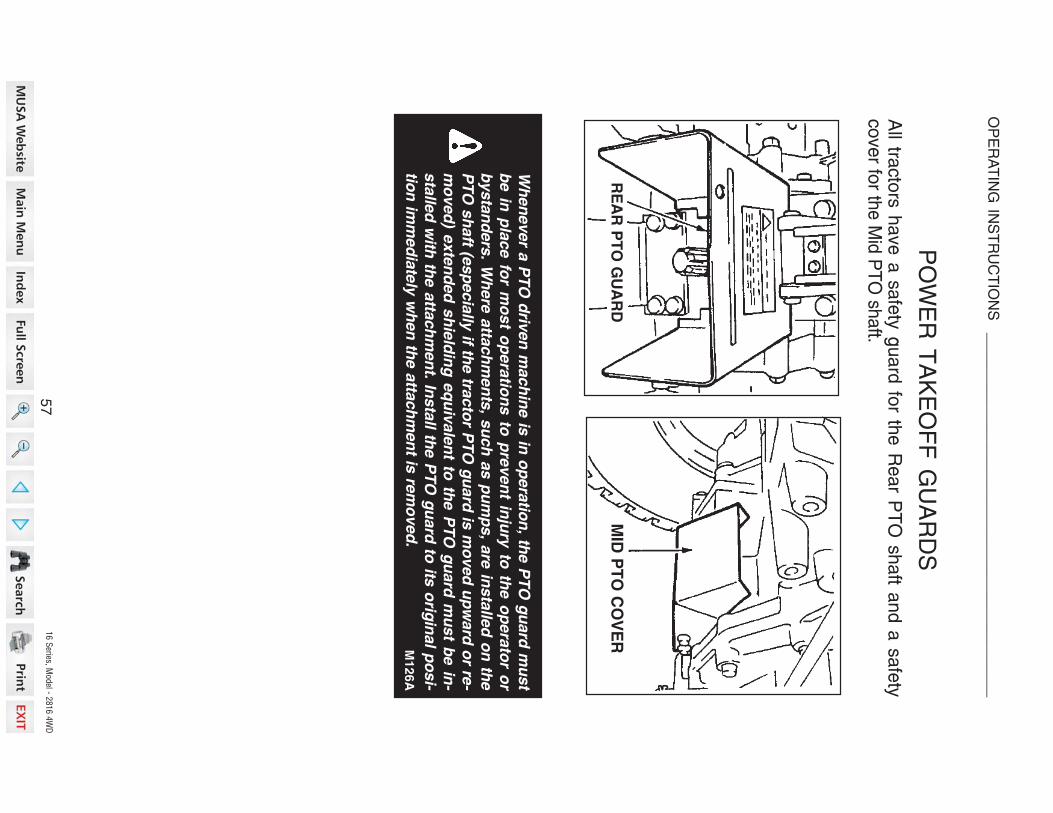
16 S
eries, Model - 2
816 4
WD
POWER
TAKEOFF
GUARDS
All tra
ctors
have
a safety
guard
for th
e R
ear P
TO
shaft a
nd a
safety
cover fo
r the M
id PTO
shaft.
Wh
en
ever a
PT
O d
riven
mach
ine is
in o
pera
tion
, the P
TO
gu
ard
mu
st
be
in p
lac
e fo
r mo
st o
pe
ratio
ns
to p
rev
en
t inju
ry to
the
op
era
tor o
r
bysta
nd
ers
. Wh
ere
atta
ch
men
ts, s
uch
as p
um
ps, a
re in
sta
lled
on
the
PT
O s
haft (e
sp
ecia
lly if th
e tra
cto
r PT
O g
uard
is m
oved
up
ward
or re
-
mo
ved
) exte
nd
ed
sh
ield
ing
eq
uiv
ale
nt to
the P
TO
gu
ard
mu
st b
e in
-
sta
lled
with
the a
ttach
men
t. Insta
ll the P
TO
gu
ard
to its
orig
inal p
osi-
tion
imm
ed
iate
ly w
hen
the a
ttach
men
t is re
mo
ved
.
RE
AR
PT
O G
UA
RD
MID
PT
O C
OV
ER
M126A
57
OP
ER
AT
ING
INS
TR
UC
TIO
NS
_
___________________________________________

16 S
eries, Model - 2
816 4
WD
PTO
OPERATING
SAFETY
Fo
r the
sa
fe o
pe
ratio
n o
f the
PT
O, fo
llow
the
se
sa
fe o
pe
ratin
g p
roce
-d
ure
s.
Three
Point H
itch
Connectin
g Im
plements
1.
Co
nn
ect th
e im
ple
me
nt to
the
hitc
h.
Se
e T
HR
EE
PO
INT
HIT
CH
SY
ST
EM
in th
is m
an
ua
l.2
.C
on
ne
ct th
e im
ple
me
nt d
rive
line
to th
e tra
cto
r.3
Ch
ec
k th
e d
rive
line
for c
orre
ct le
ng
th a
nd
for fre
e te
les
co
pic
mo
ve
me
nt b
y liftin
g a
nd
low
erin
g h
itch
syste
m. T
he
co
rrect le
ng
th is
imp
orta
nt to
pre
ve
nt th
e d
rive
line
from
hittin
g b
otto
m o
r from
se
pa
ratin
g in
an
y tra
cto
r imp
lem
en
t op
era
ting
po
sitio
n.
Drawbar C
onnectin
g Im
plements
1.
Co
nn
ect th
e im
ple
me
nt h
itch
to th
e d
raw
ba
r with
a h
ard
en
ed
ste
el
pin
. Ma
ke
su
re th
e p
in is
se
cu
rely
he
ld in
pla
ce
with
a c
otte
r pin
or
lock p
in a
nd d
oes n
ot m
ake c
onta
ct w
ith th
e im
ple
ment d
rivelin
e.
2.
Connect th
e im
ple
ment h
itch to
the tra
cto
r dra
wbar b
efo
re c
onnectin
gth
e im
ple
ment d
rivelin
e to
the P
TO
.3
.C
onnect th
e im
ple
ment d
rivelin
e to
the tra
cto
r. Check th
e d
rivelin
e fo
rcorre
ct le
ngth
and fo
r free te
lescopic
movem
ent. T
he c
orre
ct le
ngth
isim
po
rtan
t to p
rev
en
t the
driv
elin
e fro
m h
itting
bo
ttom
or fro
msepara
ting in
any tra
cto
r or im
ple
ment o
pera
ting p
ositio
n.
Wh
en
do
ing
sta
tion
ary
PT
O w
ork
an
d d
ism
ou
ntin
g fro
m th
e tra
cto
rw
ith th
e P
TO
run
nin
g, k
eep
cle
ar o
f all m
ovin
g p
arts
as th
ey a
re a
Po
ten
tial s
afe
ty h
azard
. M
127
PT
O d
riven
mach
inery
can
cau
se s
erio
us in
jury
. Befo
re w
ork
ing
on
or n
ear th
e P
TO
sh
aft, o
r serv
icin
g o
r cle
arin
g th
e d
riven
mach
ine,
pu
t the P
TO
lever in
the D
ISE
NG
AG
E p
ositio
n a
nd
ST
OP
the e
ng
ine.
M1
54
IMP
OR
TA
NT:
Fo
llow
the
imp
lem
en
t ma
nu
factu
rers
reco
mm
en
da
tion
s in
ad
justin
g a
nd
alig
nin
g th
e im
ple
me
nt a
nd
imp
lem
en
t driv
elin
e w
ith th
etra
cto
r.
58
OP
ER
AT
ING
INS
TR
UC
TIO
NS
_
___________________________________________

16 S
eries, Model - 2
816 4
WD
DRAWBAR
Your tra
cto
r is e
quip
ped w
ith a
dra
wbar. U
se th
e d
raw
bar fo
r connectin
gall p
ull-b
ehin
d im
ple
ments
.
Th
e d
raw
ba
r mu
st b
e in
the
sto
rag
e p
ositio
n w
he
n u
sin
g th
e th
ree
-po
int
hitc
h.
Re
ar u
ps
et c
an
res
ult if p
ullin
g fro
m w
ron
g lo
ca
tion
on
trac
tor. H
itch
on
ly to
the
dra
wb
ar. U
se
3 p
oin
t hitc
h o
nly
with
the
imp
lem
en
ts d
es
ign
ed
for its
us
e - n
ot a
s a
dra
wb
ar
DR
AW
BA
R H
ITC
HC
ON
NE
CT
ING
PIN
HO
LE
ST
OR
AG
E P
IN H
OL
EW
ITH
OU
T M
ID P
TO
IMP
LE
ME
NT
C
ON
NE
CT
ING
PIN
HO
LE
DR
AW
BA
RO
PE
RA
TIN
GP
OS
ITIO
N
ST
OR
AG
E P
OS
ITIO
N(W
ITH
MID
PT
O)
ST
OR
AG
E P
OS
ITIO
N(W
ITH
OU
T M
ID P
TO
)
WIT
H M
ID P
TO
(OP
TIO
N)
WIT
HO
UT
MID
PT
O
Try
to b
ala
nce th
e lo
ad
prim
arily
on
the im
ple
men
t wh
eels
- a
s in
load
ing
a tra
iler o
r sp
read
er. A
vo
id o
verlo
ad
ing
the d
raw
bar. A
dd
fron
t en
d w
eig
hts
for im
pro
ve
d s
tab
ility. E
ng
ag
e th
e c
lutc
h
sm
oo
thly, a
vo
id je
rkin
g a
nd
use th
e b
rakes c
au
tiou
sly
to a
vo
id ja
ck-
kn
ifing
.
M119
59
OP
ER
AT
ING
INS
TR
UC
TIO
NS
_
___________________________________________
M117

16 S
eries, Model - 2
816 4
WD
WARNIN
G LAMPS
Th
e la
mp
sw
itch
ha
s th
ree
po
sitio
ns. T
urn
the
sw
itch
clo
ckw
ise
toillu
min
ate
the h
eadla
mp, re
ar re
d la
mp, a
nd in
stru
ment p
anel la
mps.
Pu
sh
the
flash
er c
on
trol b
utto
n d
ow
n to
op
era
te th
e a
mb
er w
arn
ing
lam
ps.
Wh
en
the
turn
sig
na
l sw
itch
is m
ove
d u
pw
ard
to m
ake
a rig
ht tu
rn, th
eR
H w
arn
ing
lam
p w
ill illum
ina
te O
N a
nd
OF
F a
nd
the
LH
lam
p w
illillu
min
ate
contin
uously.
When th
e tu
rn s
ignal s
witc
h is
moved d
ow
nw
ard
to m
ake a
left tu
rn, th
eL
H w
arn
ing
lam
p w
ill illum
ina
te O
N a
nd
OF
F a
nd
the
RH
lam
p w
illillu
min
ate
contin
uously
.
Wh
en
the
turn
sig
na
l sw
itch
is re
turn
ed
to th
e c
en
ter p
ositio
n, b
oth
warn
ing la
mps w
ill illum
inate
ON
and O
FF.
IMP
OR
TA
NT:
Wh
en
tow
ing
an
imp
lem
en
t or w
ag
on
with
the
tracto
r, the
co
mp
lete
rea
r are
a w
arn
ing
syste
m (a
mb
er w
arn
ing
lam
ps, re
ar re
d la
mp
an
d S
MV
em
ble
m) m
ust b
e e
asily
se
en
by a
ny v
eh
icle
op
era
tor c
om
ing
ne
ar th
e tra
cto
r.
FL
AS
HE
RC
ON
TR
OL
BU
TT
ON
TU
RN
SIG
NA
L
SW
ITC
H
LA
MP
SW
ITC
H
60
OP
ER
AT
ING
INS
TR
UC
TIO
NS
_
___________________________________________

16 S
eries, Model - 2
816 4
WD
REAR
WORK
LAMP
(IF E
QUIPPED)
Th
e re
ar w
ork
lam
p is
turn
ed
on
by th
e s
witc
h o
n th
e la
mp
. Th
e s
tarte
rke
y s
witc
h m
ust b
e in
the
ON
po
sitio
n b
efo
re th
e w
ork
lam
p c
an
be
turn
ed o
n.
IMP
OR
TA
NT:
Do n
ot tu
rn o
n th
e re
ar w
ork
lam
p w
hile
travellin
g o
n p
ub -
lic ro
ads.
61
OP
ER
AT
ING
INS
TR
UC
TIO
NS
_
___________________________________________

16 S
eries, Model - 2
816 4
WD
CONNECTIN
G IM
PLEMENT
TO
DRAWBAR
Th
e c
orre
ct c
on
ne
ctio
n o
f the
imp
lem
en
t to th
e d
raw
ba
r will p
reve
nt
stre
ss o
n b
oth
the tra
cto
r and th
e im
ple
ment.
To a
ssure
pro
per tra
cto
r opera
tion a
nd o
ptim
um
imple
ment p
erfo
rmance,
the im
ple
ment m
ust b
e c
onnecte
d to
the d
raw
bar c
orre
ctly.
1.
Connect p
ull-b
ehin
d im
ple
ments
to th
e d
raw
bar o
nly.
2.
Use
a h
ard
en
ed
ste
el h
itch
pin
to c
on
ne
ct th
e im
ple
-m
en
t to th
e d
raw
ba
r. Ma
ke
sure
the p
in is
held
secure
lyin
pla
ce w
ith a
lock p
in.
3.
Wh
en
w
ork
ing
w
ith
the
dra
wb
ar,
rais
e
the
lo
we
rlin
ks a
s h
igh
as p
ossib
le to
pre
ve
nt
inte
rfere
nc
e
be
-tw
ee
n th
e lo
we
r links a
nd
the im
ple
ment.
4.
Th
e d
raw
ba
r pro
vid
es th
esta
ndard
hitc
h d
ista
nce fro
mth
e e
nd
of th
e P
TO
sh
aft to
the c
ente
rline
of
the
re
ar
ho
le in
the
dra
wb
ar. T
his
isn
ec
es
sa
ry
for
sa
fe
PT
Oo
pe
ratio
n o
f tra
iling
ty
pe
eq
uip
me
nt.
IMP
OR
TA
NT
:T
he m
axim
um
fixed d
raw
bar v
ertic
al lo
ad is
300 lb
s (1
36
kg
).
TR
AC
TO
R D
RA
WB
AR
IMP
LE
ME
NT
HIT
CH
IMP
LE
ME
NT
HIT
CH
WIT
H C
LE
VIS
RE
AR
PT
O S
HA
FT
DR
AW
BA
R
PT
O R
PM
54
0
PT
O S
HA
FT
DIA
ME
TE
R
1.3
75
In.
(34.9
mm
)
DIM
EN
SIO
N A
14 In
.(3
56 m
m)
LO
CK
PIN
62
FIE
LD
OP
ER
AT
ION
__
__
__
__
__
__
__
__
__
__
__
__
__
__
__
__
__
__
__
__
__
__
__
__
__
__

16 S
eries, Model - 2
816 4
WD
SAFETY
CHAIN
Wh
en
tow
ing
eq
uip
me
nt o
n a
hig
hw
ay, u
se
a s
afe
ty c
ha
in a
s a
n a
uxilia
ryco
nn
ectio
n b
etw
ee
n th
e tra
cto
r an
d th
e to
we
d e
qu
ipm
en
t. Th
e s
afe
tych
ain
mu
st h
ave
a ra
ting
gre
ate
r tha
n th
e g
ross lo
ad
of th
e to
we
de
qu
ipm
en
t. Co
nn
ect th
e c
ha
in to
the
tracto
r dra
wb
ar s
up
po
rt an
d th
eto
we
d e
qu
ipm
en
t as s
ho
wn
in th
e illu
stra
tion
. Ch
eck th
e a
dju
stm
en
t of
the
sa
fety
ch
ain
by tu
rnin
g th
e tra
cto
r co
mp
lete
ly to
the
righ
t an
d le
ft.A
dju
st th
e c
ha
in a
s n
ece
ssa
ry.
SA
FE
TY
CH
AIN
63
FIE
LD
OP
ER
AT
ION
__
__
__
__
__
__
__
__
__
__
__
__
__
__
__
__
__
__
__
__
__
__
__
__
__
__

16 S
eries, Model - 2
816 4
WD
THREE
POIN
T H
ITCH
SYSTEM
Th
e th
ree
po
int h
itch
syste
m g
ive
s p
ositio
n c
on
trol a
nd
dra
ft co
ntro
l (Ifequip
ped) o
f imple
ments
. This
tracto
r is e
quip
ped w
ith a
cate
gory
I hitc
h.
The th
ree-p
oin
t hitc
h d
imensio
ns a
re s
how
n in
the fo
llow
ing ta
ble
.
Imp
lem
en
t Ide
ntific
atio
nD
ime
ns
ion
s
Cat I
Imp
lem
en
t
A –
Ga
p In
top
of Im
ple
me
nt m
as
t
B –
Dia
me
ter o
f ho
les
in to
p o
f Im
ple
me
nt m
as
t
C –
Dia
me
ter o
f hitc
h p
ins
D –
Lo
wer H
itch
Pin
Inn
er S
ho
uld
er S
pre
ad
44
.5 m
m (1
-3/4
Inc
h)
19
.1 m
m (3
/4 In
ch
)
22
.2 m
m (7
/8 In
ch
)
68
2.6
mm
(26
-7/8
Inc
h)
MA
ST
HIT
CH
PIN
HIT
CH
PIN
64
FIE
LD
OP
ER
AT
ION
__
__
__
__
__
__
__
__
__
__
__
__
__
__
__
__
__
__
__
__
__
__
__
__
__
__

16 S
eries, Model - 2
816 4
WD
HITCH
SYSTEM
AD
JUSTMENTS
Th
e u
pp
er a
nd
low
er lin
ks m
ust
be
ad
juste
d c
orre
ctly
so
the
im-
ple
me
nt c
an
wo
rk a
t the
ne
ed
ed
de
pth
an
d th
e lin
ks a
re fre
e to
mo
ve
u
p
an
d
do
wn
w
ith
the
sh
ap
e o
f the
gro
un
d.
1.
Co
nn
ec
t the
lift link
s to
the
tracto
r an
d to
the
low
er lin
ks.
Ma
ke
su
re th
e lift lin
ks
are
insta
lled
on
the
pro
pe
r sid
es
as s
ho
wn
belo
w.
2.
Th
e R
H s
ide
lift link is
ad
-ju
sta
ble
by tu
rnb
uckle
to o
b-
tain
the
de
sire
d p
ositio
n o
f the
hitc
h p
oin
t.T
urn
the
turn
bu
ckle
clo
ckw
ise
to s
ho
rten
the
link o
r co
un
ter-
clo
ckw
ise
to le
ng
the
n th
e lin
k.
IMP
OR
TA
NT:
Afte
r the
lift link is
ad
juste
d, m
ake
su
re th
e lo
ckn
ut is
tighte
ned a
gain
st th
e tu
rnbuckle
.
LIF
T
LIN
KS
STA
BIL
IZE
RS
LO
WE
R L
INK
S
UP
PE
R
LIN
K
Lift L
inks
LO
CK
NU
T
TU
RN
BU
CK
LE
RH
LIF
T L
INK
LH
LIF
T L
INK
65
FIE
LD
OP
ER
AT
ION
__
__
__
__
__
__
__
__
__
__
__
__
__
__
__
__
__
__
__
__
__
__
__
__
__
__

16 S
eries, Model - 2
816 4
WD
Upper L
ink
Th
e le
ng
th A
of th
e u
pp
er lin
k c
an
be
ad
juste
d fro
m 4
70
to 7
50
mm
(18
.5 to
29
.5 in
ch
es).
Tu
rn
the
tu
rnb
uc
kle
c
loc
kw
ise
to
sh
orte
n th
e lin
k o
r co
un
terc
lockw
ise
to le
ng
the
n th
e lin
k.
IMPORTANT:
Afte
r the
up
pe
r link is
co
rrectly
ad
juste
d, m
ake
su
re th
elo
ck n
ut is
tighte
ned a
gain
st th
e tu
rnbuckle
.
Stabiliz
er
Wh
en
sid
e m
ove
me
nt o
f the
hitc
his
un
de
sira
ble
or h
aza
rdo
us, th
ela
tera
l sw
ing
is a
dju
ste
d b
y th
etu
rnb
uckle
on
the
sta
biliz
er.
Tu
rn th
e tu
rnb
uckle
clo
ckw
ise
tole
ng
the
n
the
s
tab
ilize
r o
rco
un
terc
lockw
ise
to s
ho
rten
the
sta
biliz
er.
IMP
OR
TA
NT:
Afte
r ma
kin
g fin
al
ad
justm
en
ts, c
are
fully
rais
e th
eim
ple
me
nt to
ma
ke
su
re th
at th
ere
is p
rop
er c
lea
ran
ce
be
twe
en
the
imp
lem
en
t a
nd
tra
cto
rco
mp
on
en
ts.
NO
TE
:M
ake sure the lock nut istig
hte
ne
d
afte
r a
dju
sting
th
estabilizer.
UP
PE
R
LIN
K
TU
RN
BU
CK
LE
LO
CK
NU
T
TU
RN
BU
CK
LE
LO
CK
NU
T
TU
RN
BU
CK
LE
LO
CK
NU
T
HOOK
66
FIE
LD
OP
ER
AT
ION
__
__
__
__
__
__
__
__
__
__
__
__
__
__
__
__
__
__
__
__
__
__
__
__
__
__

16 S
eries, Model - 2
816 4
WD
HITCH
OPERATIO
N
Connectin
g Im
plement to
Hitc
h
To
co
nn
ect a
n im
ple
me
nt to
the
hitc
h, u
se
the
follo
win
g p
roce
du
re:
NO
TE
: B
e sure the tractor and implem
ent are on level ground.
1.
Put th
e d
raw
bar in
the s
tora
ge p
ositio
n.
2.
Slo
wly
move th
e tra
cto
r backw
ard
s to
the im
ple
ment.
3.
When th
e h
itch p
oin
ts o
n th
e tra
cto
r and im
ple
ment a
re in
the c
orre
ct
positio
n, s
top th
e tra
cto
r.4
.A
pply
the p
ark
bra
ke a
nd s
top th
e e
ngin
e.
5.
Connect th
e im
ple
ment to
the U
pper a
nd L
ow
er L
inks.
6.
Ad
just th
e U
pp
er a
nd
Lo
we
r Lin
ks a
s n
ece
ssa
ry. Se
e H
itch
Syste
mA
dju
stm
ents
in th
is m
anual.
Disconnectin
g Im
plement fro
m H
itch
To d
isconnect a
n im
ple
ment fro
m th
e h
itch, u
se th
e fo
llow
ing p
rocedure
:
NO
TE
: B
e sure the tractor and implem
ent are on level ground.
1.
Sto
p th
e tra
cto
r co
mp
lete
ly a
nd
ap
ply
the
pa
rk b
rake
.2
.D
ise
ng
ag
e th
e P
TO
, low
er th
e im
ple
me
nt to
the
gro
un
d.
3.
Ge
ar D
rive
: Pla
ce
the
ge
ar s
hift a
nd
ran
ge
sh
ift leve
rs in
Ne
utra
l.H
yd
rosta
tic D
rive
: Re
lea
se
the
sp
ee
d lo
ck le
ve
r, an
d p
lace
the
ran
ge
sh
ift leve
r in N
eu
tral.
4.
Sto
p th
e e
ng
ine
an
d re
mo
ve
the
ke
y fro
m th
e k
ey s
witc
h b
efo
rele
avin
g th
e tra
cto
r.5
.D
isco
nn
ect th
e im
ple
me
nt fro
m th
e h
itch
.
NO
TE
:B
e sure the tractor and implem
ent are stable and free from any
tendency to roll over.
67
FIE
LD
OP
ER
AT
ION
__
__
__
__
__
__
__
__
__
__
__
__
__
__
__
__
__
__
__
__
__
__
__
__
__
__

16 S
eries, Model - 2
816 4
WD
Hitc
h C
ontro
l Lever
HIT
CH
CO
NT
RO
L L
EV
ER
Th
e h
itch
co
ntro
l leve
r is u
se
d to
rais
e o
r low
er th
e im
ple
me
nt m
ou
nte
dto
the
thre
e p
oin
t hitc
h. T
o ra
ise
the
hitc
h, m
ove
the
leve
r to th
e re
ar. T
olo
we
r the
hitc
h, m
ove
the
leve
r forw
ard
.A
dju
sta
ble
sto
ps a
re p
rovid
ed
for u
se
wh
en
eve
r it is d
esira
ble
to re
turn
the
hitc
h c
on
trol le
ve
r to th
e s
am
e o
pe
ratin
g p
ositio
n.
IMP
OR
TA
NT:
Po
sitio
n o
f the
rais
e s
top
sh
ou
ld n
ot b
e s
et s
o re
arw
ard
tha
t a in
su
fficie
nt fre
e p
lay o
f the
lift arm
s is
ava
ilab
le a
t the
hig
he
st
po
sitio
n w
he
n h
itch
co
ntro
l leve
r is m
ove
d u
ntil th
e le
ve
r is re
ach
ed
toth
e ra
ise s
top.
RA
ISE
ST
OP
LO
WE
R S
TO
P
RA
ISE
ST
OP
LO
WE
R
ST
OP
HIT
CH
CO
NT
RO
L
LE
VE
R
68
FIE
LD
OP
ER
AT
ION
__
__
__
__
__
__
__
__
__
__
__
__
__
__
__
__
__
__
__
__
__
__
__
__
__
__

16 S
eries, Model - 2
816 4
WD
Draft C
ontro
l Lever (If E
quipped)
Dra
ft c
on
trol
ca
n
be
u
se
d
toa
uto
ma
tica
lly lift a
nd
low
er a
nim
ple
me
nt to
ma
inta
in a
co
nsta
nt
loa
d th
rou
gh
va
riab
le s
oil c
on
di-
tion
s. T
he
am
ou
nt o
f dra
ft ca
nb
e a
dju
ste
d fo
r the
imp
lem
en
tb
ein
g u
se
d.
DR
AF
T C
ON
TR
OL
LE
VE
RLIG
HT
HEAVY
To
se
lect th
e c
orre
ct p
ositio
n fo
r the
dra
ft co
ntro
l leve
r, the
tracto
r an
dim
ple
ment m
ust b
e o
pera
ted in
a fie
ld.
ST
EP
1ST
OP
PE
R
DR
AF
TL
OC
K
LIG
HT
DR
AF
T C
ON
TR
OL
LE
VE
R
ST
EP
3
HE
AV
Y
ST
EP
2H
ITC
H C
ON
TR
OL
LE
VE
R
RA
ISE
LO
WE
R
Lo
we
r the
imp
lem
en
t an
d ro
tate
the s
topper lo
cate
d o
n th
e to
p o
fth
e u
pper lin
k b
racket.
Mo
ve
the
dra
ft co
ntro
l leve
r rea
r-w
ard
to s
ele
ct th
e c
orre
ct p
osi-
tion o
f the le
ver. If th
e im
ple
ment
is
lifting
u
p,
mo
ve
th
e
lev
er
forw
ard
. If the
en
gin
e R
PM
isd
ecre
asin
g, m
ove
the
leve
r rea
r-w
ard
. The d
epth
of th
e im
ple
ment
will b
e a
uto
ma
tica
lly c
on
trolle
dby th
e d
raft o
n th
e im
ple
ment.
Slo
wly
mo
ve
the
hitc
h c
on
trol
leve
r forw
ard
un
til the
imp
lem
en
tis
at th
e n
ee
de
d d
ep
th.
69
FIE
LD
OP
ER
AT
ION
__
__
__
__
__
__
__
__
__
__
__
__
__
__
__
__
__
__
__
__
__
__
__
__
__
__

16 S
eries, Model - 2
816 4
WD
Operatin
g w
ith D
raft C
ontro
l (IF
EQ
UIP
PE
D)
Fo
r exa
mp
le, th
e d
raft c
on
trol a
dju
stm
en
t for a
mo
ldb
oa
rd p
low
is a
sfo
llow
s:
1.
Se
t the
up
pe
r link a
t the
56
0 m
m (2
2-in
ch
es) le
ng
th, p
in to
pin
.
2.
Pla
ce
the
dra
ft co
ntro
l leve
r at th
e c
en
ter o
f its o
pe
ratin
g ra
ng
e.
3.
Sta
rting
at th
e e
nd
of th
e fie
ld, m
ove
the
hitc
h c
on
trol le
ve
r fully
for-
wa
rd to
the
LO
WE
R p
ositio
n a
nd
driv
e a
he
ad
se
ve
ral fe
et.
4.
Sto
p th
e tra
cto
r an
d a
dju
st th
e le
ng
th o
f the
up
pe
r link to
leve
l the
plo
w fro
nt to
rea
r.
5.
Ad
just th
e lift lin
k tu
rnb
uckle
to le
ve
l the
plo
w s
ide
to s
ide
.
6.
Afte
r the
plo
w h
as b
ee
n le
ve
led
, ad
just th
e d
raft c
on
trol le
ve
r eith
er
forw
ard
(to g
o d
ee
pe
r) or re
arw
ard
(for s
ha
llow
er d
ep
th) u
ntil th
ed
esire
d d
ep
th is
rea
ch
ed
.
7.
If the
dro
p a
ctio
n o
f the
plo
w is
too
fast, ro
tate
the
hyd
rau
lic flo
wco
ntro
l kn
ob
slo
wly
un
til the
plo
w re
acts
at th
e d
esire
d s
pe
ed
. Se
eH
itch
Lo
we
ring
Sp
ee
d A
dju
stm
en
t in th
is m
an
ua
l.
8.
Wh
en
the
co
ntro
l leve
rs a
re s
et fo
r the
field
co
nd
ition
s, s
et th
e s
top
so
the
hitc
h c
on
trol le
ve
r is re
turn
ed
to th
is p
ositio
n e
ach
time
the
plo
w is
low
ere
d in
to th
e g
rou
nd
.
9.
Wh
en
rea
ch
ing
the
en
d o
f the
field
, mo
ve
the
hitc
h c
on
trol le
ve
rre
arw
ard
to lift th
e p
low
to tra
nsp
ort p
ositio
n.
10
.R
e-e
nte
r the
field
an
d lo
we
r the
plo
w b
y m
ovin
g th
e h
itch
co
ntro
lle
ve
r forw
ard
to th
e s
top
.
11
.T
he
plo
w w
ill ma
inta
in th
e d
esire
d d
ep
th a
s p
revio
usly
se
t by th
ed
raft c
on
trol le
ve
r.
70
FIE
LD
OP
ER
AT
ION
__
__
__
__
__
__
__
__
__
__
__
__
__
__
__
__
__
__
__
__
__
__
__
__
__
__

16 S
eries, Model - 2
816 4
WD
Hitc
h Lowerin
g S
peed
Adjustm
ent
To
ad
just th
e h
itch
low
erin
g s
pe
ed
, use
the
follo
win
g p
roce
du
re:
1.
Mo
ve
the
hitc
h c
on
trol le
ve
r for-
wa
rd to
low
er th
e im
ple
me
nts
.
2.
Tu
rn th
e h
yd
rau
lic flo
w c
on
trol
kn
ob
to
a
dju
st
the
lo
we
ring
sp
ee
d. T
urn
the
kn
ob
co
un
ter
clo
ckw
ise
to in
cre
ase
the
low
er-
ing
sp
ee
d. T
urn
the
kn
ob
clo
ck-
wis
e to
de
cre
ase
the
sp
ee
d o
rlo
ck th
e h
itch
.
3.
Afte
r ad
justin
g th
e s
pe
ed
, rais
eth
e h
itch
an
d th
en
low
er it to
ch
eck th
e s
pe
ed
.
NO
TE
: W
he
n tra
nsp
ortin
g th
e tra
cto
r on
the
roa
d w
ith th
e im
ple
me
nt
mounte
d o
n th
e th
ree p
oin
t hitc
h, a
lways s
et th
e flo
w c
ontro
l knob to
the
LO
CK
positio
n.
IMP
OR
TA
NT:
Ne
ve
r pa
rk a
tracto
r with
an
imp
lem
en
t in th
e ra
ise
dp
ositio
n. M
ovin
g th
e c
on
trol le
ve
r forw
ard
will lo
we
r the
imp
lem
en
t eve
nth
ou
gh
the
en
gin
e is
no
t run
nin
g. If it is
ne
ce
ssa
ry to
se
rvic
e th
eim
ple
me
nt in
the
rais
ed
po
sitio
n, u
se
jack s
tan
ds to
sa
fely
blo
ck th
eim
ple
me
nt in
pla
ce
. Pu
t the
hyd
rau
lic flo
w c
on
trol k
no
b in
the
LO
CK
po
sitio
n.
Lo
wer o
r blo
ck e
levate
d im
ple
men
ts a
nd
oth
er a
ttach
men
ts b
efo
reserv
icin
g o
r wh
en
leavin
g th
e e
qu
ipm
en
t.M132A
HY
DR
AU
LIC
FL
OW
CO
NT
RO
L K
NO
B
FA
ST
SLO
W
LO
CK
ST
EP
1
71
FIE
LD
OP
ER
AT
ION
__
__
__
__
__
__
__
__
__
__
__
__
__
__
__
__
__
__
__
__
__
__
__
__
__
__

16 S
eries, Model - 2
816 4
WD
REMOTE
HYDRAULIC
CONTROL V
ALVE
(IF EQUIPPED)
A d
ou
ble
actin
g re
mo
te h
yd
rau
lic c
on
trol v
alv
e w
ith a
“floa
t po
sitio
n”, is
ava
ilable
from
your D
eale
r or F
acto
ry Insta
lled.
If eq
uip
pe
d, th
e c
on
trol le
ve
r is lo
ca
ted
on
the
righ
t sid
e.
RE
MO
TE
H
YD
RA
UL
IC
CO
NT
RO
L L
EV
ER
Co
nn
ect th
e im
ple
me
nt h
ose
s to
the
rem
ote
hyd
rau
lic c
ou
ple
rs s
o th
at
the
imp
lem
en
t low
ers
wh
en
the
co
ntro
l leve
r is p
ush
ed
forw
ard
an
dra
ise
s w
he
n th
e le
ve
r is p
ulle
d re
arw
ard
. Sw
itch
the
ho
se
s if th
e im
ple
-m
ent w
ork
s in
the o
pposite
way.
HY
DR
AU
LIC
CO
UP
LE
RS
72
FIE
LD
OP
ER
AT
ION
__
__
__
__
__
__
__
__
__
__
__
__
__
__
__
__
__
__
__
__
__
__
__
__
__
__

16 S
eries, Model - 2
816 4
WD
REMOTE
HYDRAULICS
OPERATIO
N (IF
EQUIPPED)
RE
MO
TE
H
YD
RA
UL
IC
CO
NT
RO
L L
EV
ER
Float O
peratio
n
To
op
era
te th
e re
mo
te h
yd
rau
lics in
a flo
at c
on
ditio
n, m
ove
the
co
ntro
lle
ve
r fully
forw
ard
to th
e d
ete
nt p
ositio
n.
Th
e le
ve
r will n
ot re
turn
to n
eu
tral a
uto
ma
tica
lly w
he
n in
the
floa
tp
ositio
n.
IMP
OR
TA
NT
:If im
ple
me
nt is
atta
ch
ed
tha
t ha
s s
ing
le a
ctin
g c
ylin
de
rs,
alw
ays u
se
the
“FL
OA
T” p
ositio
n w
he
n lo
we
ring
. Co
ntin
ua
l use
of th
e“L
OW
ER
” po
sitio
n w
ill ca
use
ove
rhe
atin
g a
nd
po
ssib
le d
am
ag
e to
the
hyd
rau
lic s
yste
m.
NO
TE
: T
he
co
ntro
l leve
r for th
e re
mo
te h
yd
rau
lic v
alv
e m
ust b
e in
the
ne
utra
l for th
e th
ree
po
int h
itch
to o
pe
rate
.
IMP
OR
TA
NT:
Ne
ve
r pa
rk a
tracto
r with
an
imp
lem
en
t in th
e ra
ise
dp
ositio
n. M
ovin
g th
e c
on
trol le
ve
r forw
ard
will lo
we
r the
imp
lem
en
t eve
nth
ou
gh
the
en
gin
e is
no
t run
nin
g. If it is
ne
ce
ssa
ry to
se
rvic
e th
eim
ple
me
nt in
the
rais
ed
po
sitio
n, u
se
jack s
tan
ds to
sa
fely
blo
ck th
eim
ple
me
nt in
pla
ce
. Pu
t the
hyd
rau
lic flo
w c
on
trol k
no
b in
the
LO
CK
po
sitio
n.
FL
OA
T P
OS
ITIO
N
73
FIE
LD
OP
ER
AT
ION
__
__
__
__
__
__
__
__
__
__
__
__
__
__
__
__
__
__
__
__
__
__
__
__
__
__

16 S
eries, Model - 2
816 4
WD
HYDRAULIC
BLOCK
A h
ydra
ulic
blo
ck is
locate
d o
n th
e rig
ht s
ide o
f the tra
cto
r. This
blo
ck c
an
pro
vid
e a
n e
xte
rna
l hyd
rau
lic c
ircu
it for lo
ad
er u
se
or o
the
r ap
plic
atio
ns.
See y
our d
eale
r.
IMP
OR
TA
NT: N
eve
r pa
rk a
tracto
r with
an
imp
lem
en
t in th
e ra
ise
dp
ositio
n. M
ovin
g th
e c
on
trol le
ve
r forw
ard
will lo
we
r the
imp
lem
en
t eve
nth
ou
gh
the
en
gin
e is
no
t run
nin
g. If it is
ne
ce
ssa
ry to
se
rvic
e th
eim
ple
me
nt in
the
rais
ed
po
sitio
n, u
se
jack s
tan
ds to
sa
fely
blo
ck
the
imp
lem
en
t in p
lace
. Pu
t the
hyd
rau
lic flo
w c
on
trol k
no
b in
the
LO
CK
po
sitio
n.
IMP
OR
TA
NT:
Wh
en
eve
r the
sh
ut o
ff pla
te is
se
t at th
e “S
” po
sitio
n,
ne
ve
r plu
g th
e in
let a
nd
ou
tlet o
f the
hyd
rau
lic b
lock. C
ha
ng
e th
e s
et
po
sitio
n o
f sh
ut-o
ff pla
te to
“0” p
ositio
n, if th
e re
mo
te a
ttach
me
nt is
no
tin
sta
lled
. Fa
ilure
to d
o s
o w
ill ca
use
da
ma
ge
to th
e h
yd
rau
lic s
yste
m.
HYDRAULIC
BLOCK
SH
UT
-OF
F
PL
AT
E
74
FIE
LD
OP
ER
AT
ION
__
__
__
__
__
__
__
__
__
__
__
__
__
__
__
__
__
__
__
__
__
__
__
__
__
__

16 S
eries, Model - 2
816 4
WD
Adding
Fluid
afte
r Connectin
g C
ylin
ders
and
Hoses
Opera
te th
e e
ngin
e a
t a m
odera
te id
le s
peed. S
et th
e s
troke s
top a
t the
yo
ke
en
d o
f the
cylin
de
r rod
to p
rovid
e m
axim
um
stro
ke
. Th
en
op
era
teth
e c
ylin
de
r in b
oth
dire
ctio
ns a
bo
ut te
n tim
es, b
y m
ovin
g th
e c
on
trol
lever u
p a
nd d
ow
n.
This
will fill th
e c
ylin
der a
nd h
oses w
ith flu
id a
nd re
move th
e a
ir from
the
syste
m. F
ill the
cylin
de
r co
mp
lete
ly, sto
p th
e e
ng
ine
an
d c
he
ck th
e flu
idle
vel w
ith th
e tra
nsm
issio
n d
ipstic
k.
Add s
uffic
ient, c
lean s
pecifie
d flu
id to
brin
g th
e o
il up to
the p
roper le
vel.
See T
RA
NS
MIS
SIO
N A
ND
HY
DR
AU
LIC
LU
BR
ICA
TIO
N in
this
manual.
NO
TE
: If a
ny o
f the
hyd
rau
lic u
nits
are
rem
ove
d a
nd
rep
lace
d fo
r an
yre
ason, c
heck th
e o
il level a
nd a
dd th
e s
pecifie
d flu
id to
the tra
nsm
issio
nto
brin
g th
e o
il up to
the p
roper le
vel.
Wh
en
rem
ote
cylin
ders
are
co
nn
ecte
d to
the h
yd
rau
lic s
yste
m, c
ycle
the c
on
trol le
ver a
bo
ut th
ree tim
es to
rem
ove a
ir from
the c
ylin
der
an
d h
os
es
. With
air in
the
sy
ste
m, ra
ise
d e
qu
ipm
en
t ca
n d
rop
accid
en
tally
an
d c
au
se p
ers
on
al in
jury
or m
ach
ine d
am
ag
e.
Hyd
rau
lic o
il or d
iesel fu
el le
akin
g u
nd
er p
ressu
re c
an
pen
etra
te th
e
skin
an
d c
au
se in
fectio
n o
r oth
er in
jury
.
To
Pre
ven
t Pers
on
al In
jury
:
Relie
ve a
ll pre
ssu
re, b
efo
re d
isco
nn
ectin
g flu
id lin
es.
Befo
re a
pp
lyin
g p
ressu
re, m
ake s
ure
all c
on
nectio
ns a
re tig
ht a
nd
co
mp
on
en
ts a
re in
go
od
co
nd
ition
.
Never u
se y
ou
r han
d to
ch
eck fo
r su
sp
ecte
d le
aks u
nd
er p
ressu
re.
Use a
pie
ce o
f card
bo
ard
or w
oo
d fo
r this
pu
rpo
se.
If inju
red
by le
akin
g flu
id, s
ee y
ou
r do
cto
r imm
ed
iate
ly.
Lo
we
r or b
loc
k e
lev
ate
d im
ple
me
nts
an
d o
the
r atta
ch
me
nts
befo
re s
erv
icin
g o
r wh
en
leavin
g th
e e
qu
ipm
en
t.
Th
e im
ple
men
t sh
ou
ld b
e lo
were
d to
the g
rou
nd
befo
re u
nco
up
ling
of th
e re
mo
te h
yd
rau
lic h
oses.
M1
49
A
M1
34
M1
32
A
M1
33
75
FIE
LD
OP
ER
AT
ION
__
__
__
__
__
__
__
__
__
__
__
__
__
__
__
__
__
__
__
__
__
__
__
__
__
__

16 S
eries, Model - 2
816 4
WD
76
ME
MO
__
__
__
__
__
__
__
__
__
__
__
__
__
__
__
__
__
__
__
__
__
__
__
__
__
__
__
__
__
__
__

16 S
eries, Model - 2
816 4
WD
TIR
E A
ND
RIM
EQUIPMENT
Tire
Infla
tion
Specific
atio
ns
Fo
r no
rma
l tracto
r op
era
tion
use
the
infla
tion
pre
ssu
re s
ho
wn
in th
e tire
an
d w
he
el c
ha
rt. Th
e in
flatio
n p
ressu
re a
re b
ase
d o
n c
old
infla
tion
pre
ssu
re re
co
mm
en
da
tion
s b
y T
ire a
nd
Rim
Asso
cia
tion
Inc.
Fo
r ma
xim
um
tracto
r pe
rform
an
ce
alw
ays a
dju
st th
e tire
pre
ssu
re, w
ithin
the
min
imu
m/m
axim
um
ran
ge
, to c
on
form
with
the
actu
al lo
ad
on
the
tires. U
nd
er n
orm
al c
on
ditio
ns u
se
the
min
imu
m p
ressu
re ra
ting
for
ge
ne
ral d
raw
ba
r wo
rk. U
se
the
hig
he
r pre
ss
ure
ratin
g, u
p to
the
ma
xim
um
, for h
ea
vy th
ree
po
int h
itch
mo
un
ted
eq
uip
me
nt, o
r he
avy fro
nt
en
d m
ou
nte
d e
qu
ipm
en
t.
Exa
mp
le A
sh
ow
s th
e c
ross s
ectio
n o
f a tire
infla
ted
for m
axim
um
loa
db
ut w
ith a
min
imu
m lo
ad
on
the
tire. T
he
tire tre
ad
is n
ot m
akin
g fu
llco
nta
ct w
ith th
e g
rou
nd
wh
ich
will g
ive
po
or p
erfo
rma
nce
.
Exa
mp
le B
sh
ow
s th
e c
ross s
ectio
n o
f a tire
with
the
infla
ted
pre
ssu
reco
rrectly
ad
juste
d to
the
loa
d o
n th
e tire
. Th
e tire
trea
d is
ma
kin
g fu
llco
nta
ct w
ith th
e g
rou
nd
wh
ich
will g
ive
ma
xim
um
pe
rform
an
ce
.
Tire
pre
ssu
re c
an
als
o b
e a
dju
ste
d a
s re
qu
ired
to s
atis
fy th
e fo
llow
ing
req
uire
me
nts
.
A.
Se
ve
re S
erv
ice
. Tire
pre
ssu
re c
an
be
incre
ase
d 2
8 k
Pa
(4 P
SI) m
ore
tha
n th
e m
axim
um
pre
ssu
re s
ho
wn
in th
e c
ha
rt, for tire
s u
se
d in
se
ve
re s
erv
ice
. Se
ve
re s
erv
ice
inclu
de
s th
e fu
rrow
tire in
reg
ula
rp
low
ing
op
era
tion
s, th
e d
ow
nh
ill tire in
sid
eh
ill plo
win
g a
nd
in o
the
rh
illsid
e o
pe
ratio
ns.
B.
Tire
s W
ith L
iqu
id B
alla
st. In
flate
the
tires 1
4 k
Pa
(2 P
SI) m
ore
tha
nth
e re
co
mm
en
de
d p
ressu
re. T
his
will c
om
pe
nsa
te fo
r ae
ratio
n th
at
occu
rs w
he
n th
e tire
s a
re in
mo
tion
.
MA
XIM
UM
INF
LA
TIO
N
PR
ES
SU
RE
MIN
IMU
M L
OA
D
EX
AM
PL
E A
INF
LA
TIO
N
PR
ES
SU
RE
AD
JU
ST
ED
TO
TR
AC
TO
R
WE
IGH
T
EX
AM
PL
E B
IMP
OR
TA
NT:
Du
ring
tran
sp
orta
tion
on
a ra
ilroa
d c
ar o
r traile
r, the
tracto
r tires a
re o
ften
infla
ted
to h
igh
er th
an
no
rma
l op
era
ting
pre
ssu
res.
Be
fore
usin
g y
ou
r tracto
r ch
eck th
e a
ir pre
ssu
re in
the
tires to
ma
ke
su
reth
at th
e a
ir pre
ssu
re d
oe
s n
ot e
xce
ed
the
ma
xim
um
pre
ssu
res s
ho
wn
inth
e tire
and w
heel e
quip
ment c
hart.7
7
TIRES/W
HEELS/SPACING/BALLAST
__
__
__
__
__
__
__
__
__
__
__
__
__
__
__
__
__
__
__
_

16 S
eries, Model - 2
816 4
WD
A tire
ca
n e
xp
lod
e d
urin
g in
flatio
n a
nd
ca
us
e s
erio
us
inju
ry o
rd
eath
. Never in
cre
ase a
ir pre
ssu
re b
eyo
nd
35 P
SI to
seat th
e b
ead
on
the rim
. Rep
lace a
tire if it h
as a
defe
ct. R
ep
lace a
wh
eel rim
wh
ich
has c
racks, w
ear o
r severe
rust. M
ake s
ure
that a
ll the a
ir isre
mo
ved
from
a tire
befo
re re
mo
vin
g th
e tire
from
the rim
. Never
use fo
rce o
n a
n in
flate
d o
r partia
lly in
flate
d tire
. Make s
ure
the tire
is c
orre
ctly
seate
d b
efo
re in
flatin
g.
M170
Tire
Load C
apacity
Th
e m
axim
um
loa
d c
ap
acity
, sh
ow
n in
the
tire p
ressu
re a
nd
loa
dca
pa
city
ch
art, is
of th
e w
he
el w
ith th
e tire
infla
ted
to th
e m
axim
um
pre
ssure
. Do n
ot e
xceed th
e m
axim
um
load c
apacity
of th
e tire
.
2816 4
WD
Po
sitio
nT
ire S
ize
Tire
Type
Tire
SLR
(in.)
Tire
Cap.
@ 2
0 m
ph
lb. @
psi
Ro
lling
Circ
. (in.)
De
scrip
tion
Re
ar
11.2
x2
4A
g T
ire20.1
1650@
18
13
04 p
ly, R-1
Fro
nt
7x1
6A
g T
ire13.4
1100 @
36
87
6 p
ly, R-1
Re
ar
15
x1
9.5
Industria
l Tire
17.9
4170 @
30
117
6 p
ly, R-4
Fro
nt
27
x8
.50
-15
Industria
l Tire
12.3
1570 @
40
80
6 p
ly, R-4
Re
ar
13
.6x1
6T
urf T
ire17.5
1570 @
14
115
4 p
ly, R-3
Fro
nt
25
x8
.50
-14
Turf T
ire11
.31060@
22
74
4 p
ly, R-3
78
TIRES/W
HEELS/SPACING/BALLAST
__
__
__
__
__
__
__
__
__
__
__
__
__
__
__
__
__
__
__
_

16 S
eries, Model - 2
816 4
WD
Check A
ir Pressure
Tir
e P
ressu
re C
heck In
terval .... E
very
50 h
ours
of o
pera
tion o
r weekly.
Check th
e c
onditio
n o
f the tire
s a
nd rim
s fo
r wear o
r dam
age. K
eep th
etire
s in
flate
d to
the
reco
mm
en
de
d p
ressu
res. S
ee
Tire
an
d W
he
el
Sp
ecific
atio
ns in
this
ma
nu
al fo
r reco
mm
en
de
d in
flatio
n p
ressu
res fo
reach tire
siz
e.
For tire
s e
quip
ped w
ith liq
uid
balla
st, c
heck th
e a
ir pre
ssure
as fo
llow
s:
1.
Use a
n a
ir-wate
r gauge. T
he v
alv
e m
ust b
e a
t the b
otto
m o
f the tire
toget a
n a
ccura
te re
adin
g.
2.
Use a
sta
ndard
air g
auge a
s fo
llow
s:
A.
The v
alv
e m
ust b
e a
t the to
p o
f the tire
.B
.M
easure
the rim
dia
mete
r.C
.A
dd
3.5
kP
a (1
/2 P
SI) fo
r ea
ch
30
5 m
m (1
2 in
ch
es) o
f rim d
iam
-ete
r to th
e s
tandard
gauge re
adin
g.
Tire
Infla
tion
Procedure
A tire
can
exp
lod
e d
urin
g in
flatio
n a
nd
cau
se s
erio
us in
jury
or d
eath
.N
ever in
cre
ase a
ir pre
ssu
re b
eyo
nd
35 P
SI to
seat th
e b
ead
on
the
rim. R
ep
lace a
tire if it h
as a
defe
ct. R
ep
lace a
wh
eel rim
wh
ich
has
cra
cks, w
ear o
r severe
rust. M
ake s
ure
that a
ll the a
ir is re
mo
ved
from
a tire
befo
re re
mo
vin
g th
e tire
from
the rim
. Never u
se fo
rce
on
an
infla
ted
or p
artia
lly in
flate
d tire
. Make s
ure
the tire
is c
or-
rectly
seate
d b
efo
re in
flatin
g.
DO
NO
T in
flate
a tire
that h
as h
ad a
com
ple
te lo
ss o
f air. If th
e tire
has
lost a
ll air p
ressu
re, h
ave
a q
ua
lified
tire m
ech
an
ic s
erv
ice
the
tire.
To A
DD
air to
a p
artly
infla
ted tire
, use th
e fo
llow
ing p
rocedure
:
1.
Use
an
air h
ose
with
a re
mo
te s
hu
t off v
alv
e a
nd
a s
elf-lo
ckin
g a
irch
uck.
2.
Sta
nd b
ehin
d th
e tre
ad o
f the tire
and m
ake s
ure
all p
ers
ons a
re a
way
from
the s
ide o
f the tire
befo
re y
ou s
tart to
add a
ir.
3.
Infla
te th
e tire
to th
e re
co
mm
en
de
d a
ir pre
ssu
re. D
O N
OT
infla
te th
etire
more
than th
e re
com
mended p
ressure
.
NO
TE
:T
ires c
an
be
infla
ted
28
kP
a (4
PS
I) ove
r ma
xim
um
reco
m-
me
nd
ed
in c
ha
rt wh
en
tracto
r is u
se
d fo
r he
avy d
raft o
pe
ratio
n a
nd
gro
und c
om
pactio
n is
not a
pro
ble
m.
M1
70
79
TIRES/W
HEELS/SPACING/BALLAST
__
__
__
__
__
__
__
__
__
__
__
__
__
__
__
__
__
__
__
_

16 S
eries, Model - 2
816 4
WD
WHEEL M
OUNTING
TORQUES
Front W
heel D
isc to
Axle
Hub Bolts
...............................118 to
132 N
m (8
7 to
98 Ib
ft)Rear W
heel D
isc to
Axle
Hub Bolts
...............................118 to
132 N
m (8
7 to
98 lb
ft)Rear W
heel R
im to
Wheel D
isc N
uts
...........................152
to 172 N
m (1
12 to
127 Ib
ft)
IMPORTANT:
Check th
e w
heel b
olts
and n
uts
afte
r the firs
t 10 h
ours
of
op
era
tion
an
d a
ga
in a
fter e
ve
ry 1
00
ho
urs
of o
pe
ratio
n. A
lso
do
this
pro
cedure
any tim
e th
e w
heel o
r rim is
rem
oved.
80
TIRES/W
HEELS/SPACING/BALLAST
__
__
__
__
__
__
__
__
__
__
__
__
__
__
__
__
__
__
__
_

16 S
eries, Model - 2
816 4
WD
FRONT
WHEEL
AD
JUSTMENT
87 tO
98 L
B F
T
(118 to
132 N
m)
The fro
nt w
heels
are
tighte
ned w
ith s
ix b
olts
for M
FD
to th
e a
xle
hubs.
NO
TE
:T
he
fron
t wh
ee
l of tire
s m
ust a
lwa
ys b
e a
sse
mb
led
with
the
va
lve
sid
e o
ut.
BO
LT
S A
ND
NU
TS
PO
SIT
ION
S
Fro
nt w
heel d
isc
to a
xle
hu
b b
olts
TO
RQ
UE
118 to
132 N
m (8
7 to
98 L
B F
T)
59 to
88 N
m (4
3 to
65 L
B F
T)
Torq
ues fo
r wheel b
olts
and tie
rod e
nd n
uts
as fo
llow
s:
Tie
rod
en
d n
uts
Ch
eck th
e b
olts
to k
ee
p th
em
tigh
t at th
e in
terv
als
reco
mm
en
de
d in
the
Se
rvic
e C
ha
rt in th
is m
an
ua
l.
81
TIRES/W
HEELS/SPACING/BALLAST
__
__
__
__
__
__
__
__
__
__
__
__
__
__
__
__
__
__
__
_

16 S
eries, Model - 2
816 4
WD
Toe-in
Adjustm
ent
TO
CH
EC
K T
HE
TO
E-IN
, US
E T
HE
FO
LL
OW
ING
PR
OC
ED
UR
E:
1.
Pu
t the
tracto
r on
leve
l gro
un
d a
nd
the
wh
ee
ls in
the
stra
igh
t ah
ea
dp
ositio
n.
2.
Pla
ce c
halk
mark
s a
t poin
ts A
on th
e c
ente
rlines o
f both
front tire
s a
tth
e s
am
e h
eig
ht a
s th
e c
ente
rline o
f the h
ub c
ap.
3.
Measure
the d
ista
nce (L
1 ) betw
een th
e c
halk
mark
s a
t poin
ts A
.
4.
Move th
e tra
cto
r forw
ard
a d
ista
nce e
qual to
one-h
alf re
volu
tion o
f the
front w
heels
.
5.
Th
e c
ha
lk m
ark
s w
ill no
w b
e a
t po
ints
B. M
ea
su
re th
e d
ista
nce
(L2 )
betw
een th
e c
halk
mark
s a
t poin
ts B
.
6.
Th
e fig
ure
of L
2 m
inu
s L
1 is
the
toe
-in. M
ake
su
re th
e to
e-in
isadju
ste
d p
roperly. If n
ot, a
dju
st th
e to
e-in
.
FR
ON
T A
XL
E T
YP
E
MF
D
TO
E-IN
(L2 –
L1 )
0 t0
0.2
0 IN
CH
(0 to
5 m
m)
TU
RN
TH
E W
HE
EL
SO
NE
-HA
LF
RE
VO
LU
TIO
N
82
TIRES/W
HEELS/SPACING/BALLAST
__
__
__
__
__
__
__
__
__
__
__
__
__
__
__
__
__
__
__
_

16 S
eries, Model - 2
816 4
WD
TO
AD
JU
ST
TH
E T
OE
-IN, U
SE
TH
E F
OL
LO
WIN
G P
RO
CE
DU
RE
:
1.
Lo
os
en
the
loc
k n
uts
at b
oth
turn
bu
ckle
en
ds to
allo
w th
e tie
rod tu
rnbuckle
to tu
rn fre
ely.
2.
Turn
the tu
rnbuckle
to s
horte
n o
rle
ngth
en th
e tie
rod le
ngth
.
3.
Ma
ke
su
re th
e c
orre
ct to
e-in
isobta
ined. If n
ot, a
dju
st th
e tie
rod
length
again
.
4. A
fter a
dju
stin
g th
e to
e-in
, tigh
ten
bo
th lo
ck n
uts
to a
torq
ue
of 5
9to
88 N
m (4
3 to
65 lb
ft).
NO
TE
:1.
Th
e R
H s
ide
Tie
-Ro
d h
as a
LH
thre
ad
an
d th
e L
H s
ide
Tie
-Rod h
as a
RH
thre
ad.
Wh
en
loo
se
nin
g o
r tigh
ten
ing
the
lock-n
ut, o
r ad
justin
g th
eT
ie-R
od, m
ake s
ure
that ...
(1)
RH
sid
e T
ie-R
od
Unlo
ck
:Turn
the lo
ck-n
ut c
lockw
ise
Lo
ck
:Tu
rn th
e lo
ck-n
ut c
ou
nte
rclo
ckw
ise
Le
ng
the
n:T
urn
the
Tie
-Ro
d c
ou
nte
rclo
ckw
ise
Shorte
n:T
urn
the T
ie-R
od c
lockw
ise
(2)
LH
sid
e T
ie-R
od
Un
lock
:Tu
rn th
e lo
ck-n
ut c
ou
nte
rclo
ckw
ise
Lock
:Turn
the lo
ck-n
ut c
lockw
ise
Le
ng
the
n:T
urn
the
Tie
-Rod c
lockw
ise
Sh
orte
n:T
urn
the
Tie
-Ro
d c
ou
nte
rclo
ckw
ise
2.
On
e tu
rn o
f the
Tie
-Ro
d m
ake
s a
bo
ut 1
2 m
m (a
ha
lf inch
)diffe
rence o
f the T
oe-in
.
LO
CK
NU
T
TIE
-RO
D
TU
RN
BU
CK
LE
83
TIRES/W
HEELS/SPACING/BALLAST
__
__
__
__
__
__
__
__
__
__
__
__
__
__
__
__
__
__
__
_

16 S
eries, Model - 2
816 4
WD
TIR
E S
IZE
COMBIN
ATIO
NS
— M
FD
Yo
ur M
FD
Tra
cto
r mu
st u
se
fron
t an
d re
ar tire
co
mb
ina
tion
s th
at a
reco
rrectly
ma
tch
ed
. Th
e u
se
of re
co
mm
en
de
d tire
co
mb
ina
tion
s w
ill giv
em
axim
um
tracto
r pe
rform
an
ce
, exte
nd
ed
tire life
an
d re
du
ce
d w
ea
r on
driv
e tra
in c
om
po
ne
nts
.
IMP
OR
TA
NT:
Th
e tire
siz
e c
om
bin
atio
ns s
ho
wn
be
low
are
sp
ecifie
d to
pro
vid
e m
atc
he
d g
rou
nd
sp
ee
ds o
f the
fron
t an
d re
ar tire
s. M
ixin
g w
orn
an
d n
ew
tires o
r tires o
f diffe
ren
t dia
me
ters
or lo
ad
ed
rad
ii ca
n g
ive
inco
rrect g
rou
nd
sp
ee
d m
atc
h. W
he
n re
pla
cin
g tire
s, c
on
su
lt yo
ur D
ea
ler.
MODEL
NUM
BER
2816 4
WD
TIR
ES
IZE
SY
TL
E
Fro
nt
7-1
6R
1*
Re
ar
11
.2-2
4R
1*
Fro
nt
25
X8
.50
-14
R3
*
Re
ar
13
.6-1
6R
3*
Fro
nt
27
X8
.50
-15
R4
*
Re
ar
15
-19
.5R
4*
*R-1
–A
gric
ultu
ral tre
ad
for g
en
era
l farm
ing
*R-3
–Tu
rf tire*R
-4–
Ind
ustria
l tire
84
TIRES/W
HEELS/SPACING/BALLAST
__
__
__
__
__
__
__
__
__
__
__
__
__
__
__
__
__
__
__
_

16 S
eries, Model - 2
816 4
WD
TRACTOR
BALLAST
Ba
llast fo
r yo
ur tra
cto
r inclu
de
s fro
nt e
nd
we
igh
ts, re
ar w
he
el w
eig
hts
an
d liq
uid
ba
llast in
the
rea
r tires. F
ron
t en
d w
eig
hts
imp
rove
the
ste
erin
gch
ara
cte
ristic
wh
en
he
avy h
itch
loa
ds c
au
se
a m
ove
me
nt o
f tracto
rw
eig
ht fro
m th
e fro
nt to
the
rea
r wh
ee
ls. R
ea
r wh
ee
l we
igh
ts a
nd
ad
din
gliq
uid
to th
e re
ar tire
s in
cre
ase
tractio
n b
y p
uttin
g w
eig
ht o
n th
e d
rivin
gw
he
els
.
IMPORTANT:
Th
e M
axim
um
op
era
ting
we
igh
t of tra
cto
r sh
ou
ld n
ot
exceed th
e fo
llow
ing v
alu
es. T
he o
pera
ting w
eig
ht o
f tracto
r inclu
des th
ew
eig
ht o
f tracto
r, opera
tor, b
alla
st w
eig
ht a
nd im
ple
ment.
Fro
nt A
xle
..................................970 k
gR
ea
r Axle
.................................1
35
0kg
To
tal.........................................
2200 k
g
Front E
nd
Weights
(O
PTIO
NAL)
Fro
nt e
nd
we
igh
ts c
an
be
mo
un
ted
on
the
fron
t en
d b
racke
t of th
e tra
cto
rw
ith lo
ckin
g b
olts
an
d n
uts
. Th
e w
eig
hts
, lockin
g b
olts
an
d n
uts
are
ava
ilab
le fro
m y
ou
r De
ale
r. A m
axim
um
of s
ix w
eig
hts
at 2
2 k
g (4
9 lb
s)
ea
ch
ca
n b
e in
sta
lled
, de
pe
nd
ing
on
imp
lem
en
t ap
plic
atio
n a
nd
so
ilco
nd
ition
s.
Use
fron
t en
d w
eig
hts
as n
ee
de
d to
pro
vid
e e
ffectiv
e s
tee
ring
co
ntro
l an
dfro
nt e
nd
sta
bility
an
d to
ach
ieve
ma
xim
um
op
era
ting
effic
ien
cy a
nd
tracto
r field
pe
rform
an
ce
.
FR
ON
T E
ND
WE
IGH
T
BR
AC
KE
T
85
TIRES/W
HEELS/SPACING/BALLAST
__
__
__
__
__
__
__
__
__
__
__
__
__
__
__
__
__
__
__
_

16 S
eries, Model - 2
816 4
WD
TO
O M
UC
H C
OR
RE
CT
BA
LL
AS
TT
OO
LIT
TL
EB
AL
LA
ST
BA
LL
AS
T
NO
TE
:W
he
n
you
h
ave
to
om
uch
ba
llast in
stalle
d o
n th
etra
ctor, yo
u w
ill see
the
clea
rsh
ap
e o
f the
tire tre
ad
in th
eground w
hich is an indication ofn
o
slipp
ag
e.
With
to
o
littleballast, the tire tread m
arks will
no
t sho
w b
eca
use
of th
e tire
slippage.
86
TIRES/W
HEELS/SPACING/BALLAST
__
__
__
__
__
__
__
__
__
__
__
__
__
__
__
__
__
__
__
_

16 S
eries, Model - 2
816 4
WD
HOOD
To
do
ma
inte
na
nce
wo
rk o
n th
e e
ng
ine
lub
rica
tion
syste
m, c
oo
ling
syste
m, fu
el s
yste
m a
nd
air in
du
ctio
n s
yste
m, y
ou
mu
st lift th
e tra
cto
rh
oo
d.
Pull th
e h
ood la
tch to
rele
ase th
eh
oo
d.
Un
lock th
e ru
bb
er la
tch
es o
n to
po
f ea
ch
sid
e c
ove
r to re
lea
se
the
sid
e c
over.
Lift th
e h
oo
d a
nd
co
nn
ec
t the
Support R
od.
Rem
ove b
oth
sid
e c
overs
.
ST
EP
1S
TE
P 3
ST
EP
2S
TE
P 4
RU
BB
ER
LA
TC
H
R.H
. SID
E C
OV
ER
BO
NN
ET
PR
OP
RO
D
87
LUBRICATIO
N/FILTERS/FLUIDS
__
__
__
__
__
__
__
__
__
__
__
__
__
__
__
__
__
__
__
__
__
_

16 S
eries, Model - 2
816 4
WD
Lubric
atio
n Table
Ap
plic
atio
nK
ind
of O
ilA
PI
Cla
ss
ifi-c
atio
n
Am
bie
nt
Te
mp
era
ture
Gra
de
Sin
gle
Mu
lti
(SA
E N
o.)
De
sc
riptio
nR
ec
om
me
nd
atio
nO
il Bra
nd
En
gin
eE
ng
ine O
ilC
D
(Fo
r 15 W 40 o
il)C
itgo
-Citg
ard 500 15W
40E
xxon
-XD
3Extra 15W
40C
hevro
n-D
elo 400 15W
40M
ob
il-Devlac 1300 15W
40S
hell-R
otella T
15W40
Texaco-U
rsa Su
per P
lus 15W
40
-100C
(140F
)5W
10
W*
-20-0
0C(-4
-320F
)
-10-1
00C
(14-5
00F
)2
0W
0-2
00C
(32-6
80F
)20
10-3
00C
(50-8
60F
)30*
300C
(860F
)40
5W
-20
10W
-30
15W
-40
Use h
igh
Gra
de D
isel O
il
En
gin
e O
il
Use h
igh
Gra
de
Dis
el O
il
20W
-30
Tra
ns
mis
-sio
n o
il,fro
nt d
iff. oil
Hy
dra
ulic
Tra
ns
mis
sio
nF
luid
Hy
dra
ulic
Tra
ns
mis
sio
nF
luid
Citg
o-T
ran
sg
ard
Tra
cto
r H
yd
rau
lic F
luid
sE
xxo
n-T
orq
ue F
luid
56
Ch
evro
n-C
hevro
n 1
000 T
HF
Mo
bil-M
ob
il Flu
id 4
24
Sh
ell-D
on
ax T
DTexaco
-TD
H o
il Sp
ecia
l
Use g
oo
d g
rade g
rease, desig
ned
for p
inan
d b
ush
ing
s on
agricu
ltural eq
uip
men
t.L
ithiu
m o
r alum
iniu
m co
mp
lex type g
reasew
ith h
igh
viscosity b
ase oil, takin
ess and
mo
lybd
enu
m d
isulp
hid
e are suitab
le.G
rease app
roved
for th
e NL
GI certificatio
nm
ark GC
-LB
are recom
med
ed.
Gre
as
eN
ipp
leG
rea
se
——
88
LUBRICATIO
N/FILTERS/FLUIDS
__
__
__
__
__
__
__
__
__
__
__
__
__
__
__
__
__
__
__
__
__
_
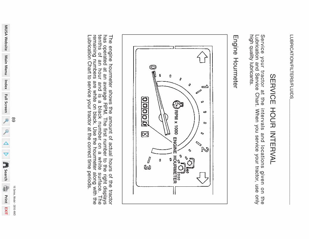
16 S
eries, Model - 2
816 4
WD
SERVIC
E H
OUR
INTERVAL
Se
rvic
e y
ou
r tra
cto
r a
t th
e in
terv
als
a
nd
lo
ca
tion
s g
ive
n o
n th
eL
ub
rica
tion
an
d S
erv
ice
Ch
art. W
he
n y
ou
se
rvic
e y
ou
r tracto
r, use
on
lyhig
h q
uality
lubric
ants
.
Engine
Hourm
eter
Th
e e
ng
ine
ho
urm
ete
r sh
ow
s th
e a
mo
un
t of a
ctu
al h
ou
rs o
f the
tracto
rh
as o
pe
rate
d a
t an
ave
rag
e R
PM
. Th
e firs
t nu
mb
er to
the
righ
t dis
pla
ys
ten
ths o
f an
ho
ur a
nd
is a
bla
ck n
um
be
r on
a w
hite
su
rface
. Th
ere
main
ing n
um
bers
are
white
on b
lack. U
se th
e h
ourm
ete
r alo
ng w
ith th
eLubric
atio
n C
hart to
serv
ice y
our tra
cto
r at th
e c
orre
ct tim
e p
erio
ds.
RP
M x
1000
EN
GIN
E H
OU
RM
ET
ER
89
LUBRICATIO
N/FILTERS/FLUIDS
__
__
__
__
__
__
__
__
__
__
__
__
__
__
__
__
__
__
__
__
__
_

16 S
eries, Model - 2
816 4
WD
Service
Afte
r Firs
t 50
Hours
1.
Engin
e O
ilD
rain
all th
e o
il from
the c
rankcase w
hile
the e
ngin
e is
warm
and re
fillw
ith n
ew
oil to
the
up
pe
r No
tch
(full) o
n th
e e
ng
ine
oil d
ipstic
k. S
ee
Engin
e O
il Change in
this
manual.
2.
Engin
e O
il Filte
rR
epla
ce th
e e
ngin
e o
il filter. S
ee E
ngin
e O
il Filte
r in th
is m
anual.
3.
Tra
nsm
issio
n &
Hydra
ulic
Syste
m (1
)T
ransm
issio
n O
ilC
he
ck th
e le
ve
l of th
e tra
nsm
issio
n o
il. Ad
d th
e s
pe
cifie
d flu
id a
sneeded to
main
tain
pro
per le
vel. S
ee T
ransm
issio
n O
il Level in
this
ma
nu
al.
(2)
Hydra
ulic
filter
Repla
ce filte
r with
a n
ew
one. S
ee H
ydra
ulic
Filte
r in th
is m
anual.
4.
Fro
nt A
xle
Lubric
ant (M
FD
)C
ha
ng
e th
e o
il. Se
e F
RO
NT
AX
LE
LU
BR
ICA
TIO
N (M
FD
) in th
ism
an
ua
l.
5.
Radia
tor C
ore
Insp
ect th
e ra
dia
tor c
ore
an
d c
lea
n if n
ece
ssa
ry. Se
e C
OO
LIN
GS
YS
TE
M in
this
manual.
6.
Hoses a
nd C
onnectio
ns b
etw
een A
ir Cle
aner a
nd M
anifo
ld.
Inspect fo
r loose fit o
r leakage. S
ee A
IR IN
DU
CT
ION
SY
ST
EM
in th
ism
an
ua
l.
7.
Wate
r Pum
p, F
an a
nd A
ltern
ato
r Belt T
ensio
nC
he
ck th
e b
elt fo
r ten
sio
n, re
pla
ce
if ne
ce
ssa
ry. Se
e F
an
Be
ltA
dju
stm
ent in
this
manual.
90
LUBRICATIO
N/FILTERS/FLUIDS
__
__
__
__
__
__
__
__
__
__
__
__
__
__
__
__
__
__
__
__
__
_

16 S
eries, Model - 2
816 4
WD
SYSTEM
CAPACITIES
SY
ST
EM
U.S
.M
EA
SU
RE
ME
TR
ICM
EA
SU
RE
IMP
ER
IAL
ME
AS
UR
E
Engin
e O
ilno filte
r change
3.9
QT
S3.7
Litre
s3.2
QT
Sw
ith filte
r change
4.4
QT
S4.2
Litre
s3.7
QT
S
Fu
el
tank
7.9
Gallo
ns
30 L
itres
6.6
Gallo
ns
Co
ola
nt
engin
e a
nd ra
dia
tor
7.1
QT
S6.7
Litre
s5.9
QT
Scoola
nt b
ottle
0.4
QT
S0.4
Litre
s0.4
QT
S
Tra
nsm
issio
n O
ilgear d
rive
Fro
nt A
xle
MF
D4.2
QT
S4.0
Litre
s3.5
QT
S
25.4
QT
S24 L
itres
21.1
QT
S
91
LUBRICATIO
N/FILTERS/FLUIDS
__
__
__
__
__
__
__
__
__
__
__
__
__
__
__
__
__
__
__
__
__
_

16 S
eries, Model - 2
816 4
WD
MA
RK
Y :
Yearly o
r 1000 H
ours, w
hich
eve
r occu
r first. A
Y : Y
early o
r as n
eeded.
No
te 1
: Co
nsu
lt yo
ur D
ea
ler.
No
te 2
: Re
pla
ce e
lem
en
t afte
r 10
clea
nin
gs o
r yea
rly.N
ote
3: A
pp
ly G
ea
r Oil.
FR
EQ
UE
NC
Y IN
HO
UR
S
CLEAN
CHANGE
CHECK
GREASE
DRAIN
NOOFPOINTSS
ER
VIC
E P
OIN
T
En
gin
e O
il Level
11
0
Fro
nt A
xle
Tie
Ro
d2
10
Fro
nt A
xle
Piv
ot P
in1
10
Po
wer S
teerin
g C
ylin
der E
nd
10
Bra
ke P
ed
al B
oss
21
0
Tra
nsm
issio
n O
il Level
11
0
Rad
iato
r Co
ola
nt L
evel
11
0
Fu
el F
ilter C
up
11
01
0
Air C
lean
er
11
01
0
Fan
Belt T
en
sio
n1
10
Grill a
nd
Ra
dia
tor A
rea
15
05
0
Tire
Pre
ssu
re4
50
Fu
el T
an
k W
ate
r Dra
in P
lug
15
0
En
gin
e O
il1
10
0
Wh
eel R
eta
inin
g B
olts
an
d N
uts
10
0
En
gin
e O
il Filte
r1
20
0
Tra
nsm
issio
n O
il1
20
0
Hy
dra
ulic
Fllte
r1
20
0
MF
D F
ron
t Axle
Lu
bric
an
t1
20
0
Clu
tch
Ped
al
12
00
Bra
ke P
ed
al
22
00
Air In
du
ctio
n S
yste
m1
20
0
En
gin
e V
alv
e C
leara
nce (S
ee N
ote
1)
b2
00
RO
PS
Eq
uip
men
t2
00
Co
olin
g S
yste
mY
YY
Air C
lea
ne
r Filte
r Ele
me
nt (S
ee
No
te 2
)1
AY
All L
ink
ag
e P
ivo
t Po
ints
(Se
e N
ote
3)
8A
Y
Th
read
s o
f 3-P
oin
t Hitc
h L
inks
2A
Y
Fu
el F
ilter
1A
Y
Hyd
rau
lic S
yste
mA
Y
Batte
ry T
erm
inals
AY
AY
92
LUBRICATIO
N/FILTERS/FLUIDS
__
__
__
__
__
__
__
__
__
__
__
__
__
__
__
__
__
__
__
__
__
_

16 Series, Model - 2816 4WD
LUBRICATION/FILTERS/FLUIDS______________________________________________________________________________________________________________________________
Fluid
Levels
and
Filters
100 HRS 1000 HRS 10 HRS 10 HRS 100 HRS
10 HRS 200 HRS
10 HRS
200 HRS 200 HRS10 HRS 50 HRS Yearly
Engine Oil - Change Radiator and Coolant - Drain,Flush and Fill
Coolant Recovery Reservoir
- CheckAir Cleaner-Clean Engine Oil - Drain
Engine Oil Filter - ChangeEngine Oil - Check
Brake Pedal - Grease
Hydraulic Filter - ChangeTransmission Oil - ChangeFuel Filter - ChangeFuel - DrainTransmission Oil - Check(Gear Drive)

16 Series, Model - 2816 4WD
LUBRICATION/FILTERS/FLUIDS ___________________________________________________________________________________
Front Axle Pivot Pin - Grease
10 HRS 10 HRS
Tie Rod End - Grease
USE NLGI No.2 MULTIPURROSE
LITHIUM EP GREASE.
10 HRS
200 HRS
200 HRS200 HRS200 HRS
Power Steering Piston End -Grease
MFD Lubricant - Check
MFD Lubricant - DrainMFD Lubricant - DrainMFD Lubricant - Change
FRONT AXLE
MFD

16 S
eries, Model - 2
816 4
WD
ENGIN
E LUBRIC
ATIO
N
Service
Specific
atio
ns
Oil L
evel C
heck In
terv
al........................................................................
Da
ily.O
il Change In
terv
al.........................................E
very
100 h
ours
(See N
OT
E)
Oil T
ype
...............................................See L
ubric
atio
n T
able
in th
is m
anual.
Oil C
apacity
—W
ithout F
ilter C
hange
....................3.7
Litre
(3.9
QT
)W
ith F
ilter C
hange
.........................4.2
Litre
(4.4
QT
)
NO
TE
: C
ha
ng
e th
e e
ng
ine
oil a
fter th
e firs
t 50
ho
urs
of o
pe
ratio
n a
nd
the
n u
se
the
reg
ula
r ch
an
ge
inte
rva
l. Ch
an
ge
the
en
gin
e o
il mo
refre
qu
en
tly w
he
n th
e o
pe
ratin
g c
on
ditio
ns a
re s
eve
re, s
uch
as, o
pe
ratin
gu
nd
er h
ea
vy lo
ad
, sta
rting
an
d s
top
pin
g w
ith fre
qu
en
cy, o
r op
era
ting
invery
hig
h o
r very
low
am
bie
nt te
mpera
ture
s.
Engine
Oil L
evel
To
ch
eck th
e e
ng
ine
oil le
ve
l, pu
tth
e tra
cto
r on
leve
l gro
un
d a
nd
sto
pth
e e
ng
ine
. Pu
ll the
dip
stic
k o
ut,
wip
e th
e d
ipstic
k w
ith a
dry
clo
tha
nd
insta
ll the
dip
stic
k to
ch
eck th
eo
il leve
l. If the
oil le
ve
l is b
elo
w th
eA
(Add) M
ark
, add o
il to ra
ise th
e o
ille
vel to
the F
(Full) M
ark
.D
o n
ot ra
ise
the
oil le
ve
l ab
ove
the
F(F
ull) M
ark
.
IMP
OR
TA
NT
: The le
vel s
hould
be c
hecked b
efo
re s
tartin
g o
f 5 m
inute
safte
r the e
ngin
e h
as b
een s
hut o
ff.
EN
GIN
E O
IL D
IPS
TIC
K
FU
LL
MA
RK
EN
GIN
E O
IL D
IPS
TIC
K
AD
D M
AR
K
95
LUBRICATIO
N/FILTERS/FLUIDS
__
__
__
__
__
__
__
__
__
__
__
__
__
__
__
__
__
__
__
__
__
_

16 S
eries, Model - 2
816 4
WD
Engine
Oil C
hange
To
ch
an
ge
the
en
gin
e o
il, pu
t the
tracto
r on
leve
l gro
un
d a
nd
sto
p th
eengin
e. C
hange th
e e
ngin
e o
il as fo
llow
s:
NO
TE
: For b
est re
sults
change th
e o
il while
the e
ngin
e is
still w
arm
.
DR
AIN
PL
UG
OIL
FIL
L C
AP
1.
Rem
ove th
e o
il pan d
rain
plu
g a
nd d
rain
the o
il from
the e
ngin
e.
2.
See E
ngin
e O
il Filte
r in th
is m
anual, if th
e filte
r is to
be c
hanged.
3.
Insta
ll the d
rain
plu
g in
the o
il pan. T
ighte
n th
e p
lug to
a to
rque o
f 50
to 6
0 N
m (3
6 to
43 lb
ft).
4.
Pu
t the
co
rrect ty
pe
an
d a
mo
un
t of n
ew
oil in
to th
e e
ng
ine
. Se
eE
ngin
e O
il Sele
ctio
n in
this
manual fo
r recom
mended o
il type.
IMPORTANT: D
o n
ot u
se
the
oil le
ve
l dip
stic
k a
s a
gu
ide
wh
en
yo
u fill
the
en
gin
e c
ran
kca
se
with
oil. A
lwa
ys m
ea
su
re th
e a
mo
un
t of o
il yo
uin
sta
ll.
5.
Sta
rt the e
ngin
e. O
pera
te th
e e
ngin
e fo
r five m
inute
s a
t 1200 rp
m.
Check fo
r oil le
aks a
t the filte
r base a
nd d
rain
plu
g.
6.
Sto
p th
e e
ng
ine
. Wa
it ap
pro
xim
ate
ly fiv
e m
inu
tes fo
r the
oil to
retu
rnto
the
oil p
an
. Ch
eck th
e o
il leve
l on
the
dip
stic
k a
nd
ad
d o
il ifn
ee
de
d.
96
LUBRICATIO
N/FILTERS/FLUIDS
__
__
__
__
__
__
__
__
__
__
__
__
__
__
__
__
__
__
__
__
__
_

16 S
eries, Model - 2
816 4
WD
Engine
Oil F
ilter
Change In
terv
al............................................E
ve
ry 2
00 h
ours
(See N
OT
E)
NO
TE
:C
ha
ng
e th
e e
ng
ine
oil filte
r afte
r the
first 5
0 h
ou
rs o
f op
era
tion
and th
en u
se th
e re
gula
r change in
terv
al.
IMP
OR
TA
NT:
Ch
an
ge
the
oil filte
ra
t the
reco
mm
en
de
d tim
e in
terv
al.
Yo
ur D
ea
ler h
as a
pp
rove
d g
en
uin
efilte
rs. D
o n
ot u
se o
ther ty
pe filte
rs.
Ch
an
ge
the
en
gin
e o
il filters
as fo
l-lo
ws :
1.
Dra
in th
e o
il from
the
en
gin
e.
Se
e E
ng
ine
Oil C
ha
ng
e in
this
ma
nu
al.
2.
Tu
rn th
e o
il filter c
ou
nte
rclo
ck-
wis
e
to
rem
ov
e.
Us
e
a
filter
wre
nch, if n
ecessary.
3.
Ap
ply
cle
an
oil to
the
O-rin
g o
nth
e n
ew
filter.
4.
Insta
ll the filte
r. Turn
the filte
r until
the O
-ring c
om
es in
conta
ct w
ith th
eca
se
su
rface
. Tig
hte
n th
e filte
r an
additio
nal 2
/3 tu
rn b
y h
and.
IMP
OR
TA
NT
:D
O N
OT
use
a filte
rw
rench to
insta
ll the o
il filter. W
hen th
efilte
r is to
o tig
ht, y
ou c
an c
ause d
am
-age to
the O
-ring a
nd filte
r.
5.
Pu
t new
oil in
the e
ngin
e. S
ee E
n-
gin
e O
il change in
this m
anual.
EN
GIN
E O
IL F
ILT
ER
INS
TA
LL
RE
MO
VE
97
LUBRICATIO
N/FILTERS/FLUIDS
__
__
__
__
__
__
__
__
__
__
__
__
__
__
__
__
__
__
__
__
__
_

16 S
eries, Model - 2
816 4
WD
Ch
ec
k a
nd
se
rvic
e c
oo
ling
sy
ste
m a
cc
ord
ing
to m
ain
ten
an
ce
in-
stru
ctio
ns. H
ot c
oo
lan
t can
sp
ray o
ut if ra
dia
tor c
ap
is re
mo
ved
wh
ilesyste
m is
ho
t. To
rem
ove ra
dia
tor c
ap
, let s
yste
m c
oo
l, turn
to firs
tn
otc
h. T
hen
wait u
ntil a
ll pre
ssu
re is
rele
ased
. Scald
ing
can
resu
ltfro
m fa
st re
mo
val o
f rad
iato
r cap
.
COOLIN
G S
YSTEM
Service
Specific
atio
ns
Co
ola
nt C
ha
ng
e In
terv
al.........................E
ve
ry 1
00
0 h
ou
rs o
r on
ce
ea
ch
ye
ar w
hic
he
ve
r occu
rs firs
tC
ap
acity
of S
yste
mE
ng
ine
an
d R
ad
iato
r..............................
6.7
Litre
s (7
.1 Q
TS
)C
oo
lan
t Bo
ttle.........................................
0.4
Litre
s (0
.4 Q
TS
)T
he
rmo
sta
t............................................. 8
2oC
to 9
5oC
(18
0oF
to 2
03
oF)
Ra
dia
tor C
ap
Pre
ssu
re..............................................
88
.2 k
Pa
(12
.8 P
SI)
Da
ily b
efo
re s
tartin
g th
e e
ng
ine
, ch
eck th
e c
oo
lan
t leve
l of th
e c
oo
lan
tre
se
rve
bo
ttle. T
he
co
ola
nt le
ve
l sh
ou
ld b
e b
etw
ee
n th
e “F
UL
L” a
nd
“LO
W” lin
es w
he
n th
e e
ng
ine
is c
oo
l.
Pressure
Coolin
g S
ystem
1.
Th
e p
ressu
re c
ap
on
a p
res-
su
re
co
olin
g
sy
ste
m
ha
s
aco
ntro
l va
lve
tha
t op
era
tes a
s a
SA
FE
TY
R
EL
IEF
V
AL
VE
to
ke
ep
the
pre
ssu
re w
ithin
the
syste
m o
pe
ratin
g ra
ng
e. O
pe
r-a
ting
th
e
en
gin
e
with
ou
t a
pre
ssu
re c
ap
or w
ith a
pre
s-
su
re c
ap
tha
t ha
s a
co
ntro
lva
lve
tha
t is n
ot s
et to
op
era
tea
t the
co
rrect p
ressu
re, c
an
ca
use
da
ma
ge
.2
.A
pre
ssu
re c
oo
ling
syste
m d
e-
cre
as
es
the
los
s o
f co
ola
nt
ca
use
d b
y e
va
po
ratio
n o
r bo
iling
. Th
e s
yste
m m
ust h
ave
go
od
se
als
at th
e ra
dia
tor c
ap
, ho
se
s a
nd
ho
se
co
nn
ectio
ns. It is
imp
orta
nt th
at
yo
u s
top
AL
L L
EA
KS
OF
AN
Y S
IZE
as s
oo
n a
s th
e le
aks a
re fo
un
d.
A s
ma
ll lea
k c
an
be
co
me
a la
rge
flow
wh
en
pre
ssu
re is
incre
ase
d in
the
co
olin
g s
yste
m. W
hile
the
tracto
r is in
op
era
tion
, a w
ea
k h
ose
ca
nb
rea
k a
nd
ca
us
e in
jury
or d
am
ag
e. C
he
ck
all h
os
es
an
d h
os
eco
nn
ectio
ns w
ith fre
qu
en
cy. K
EE
P H
OS
ES
, HO
SE
CO
NN
EC
TIO
NS
AN
D P
RE
SS
UR
E C
AP
IN G
OO
D C
ON
DIT
ION
.
M305
PR
ES
SU
RE
CA
P
98
LUBRICATIO
N/FILTERS/FLUIDS
__
__
__
__
__
__
__
__
__
__
__
__
__
__
__
__
__
__
__
__
__
_

16 S
eries, Model - 2
816 4
WD
Coolant S
olutio
ns
Your tra
ctor c
oolin
g system
is equipped
with
an
ethylene
glycol c
oolant
solutio
n th
at h
as a
high boilin
g point.
IMP
OR
TA
NT:
Ch
an
ge
the
co
ola
nt s
olu
tion
at th
e c
ha
ng
e in
terv
al
reco
mm
en
de
d in
this
ma
nu
al (S
ee
Lu
bric
atio
n a
nd
se
rvic
e C
ha
rt). Th
eh
ea
t ge
ne
rate
d b
y th
e d
iese
l en
gin
e c
au
se
s a
na
tura
l ch
an
ge
in th
ein
hib
itors
in th
e c
oola
nt w
hic
h re
sults
in lo
ss o
f corro
sio
n p
rote
ctio
n. T
he
loss o
f the in
hib
itors
may c
ause w
ate
r pum
p c
avita
tion a
nd c
ylin
der b
lock
ero
sio
n.
Insta
ll on
ly e
thyle
ne
gly
co
l co
ola
nt s
olu
tion
in th
e c
oo
ling
syste
m. U
se
ag
oo
d q
ua
lity, hig
h b
oilin
g p
oin
t, eth
yle
ne
gly
co
l tha
t do
es n
ot h
ave
an
ya
dd
itive
s to
sto
p le
aks. D
o n
ot in
sta
ll an
y ru
st in
hib
itors
tha
t are
no
tappro
ved. It is
possib
le th
at th
e ru
st in
hib
itors
and e
thyle
ne g
lycol w
ill not
mix
an
d w
ork
ag
ain
st e
ach
oth
er to
de
cre
ase
co
rrosio
n p
rote
ctio
n, fo
rmdeposits
in th
e c
oolin
g s
yste
m a
nd c
ause d
am
age to
the c
oolin
g s
yste
mand th
e ra
dia
tor.
Do n
ot u
se a
low
boilin
g p
oin
t, alc
ohol ty
pe c
oola
nt s
olu
tion.
Th
e b
olin
g p
oin
t of a
lco
ho
l is b
elo
w th
e tra
cto
r min
imu
m o
pe
ratin
g te
m-
pera
ture
, loss o
f coola
nt d
ue to
evapora
tion w
ill result.
IMPORTANT
Alw
ays h
ave
a m
inim
um
of 5
0 p
erc
en
t eth
yle
ne
gly
co
lcoola
nt in
the c
oolin
g s
yste
m a
t all tim
es a
nd a
t all a
mbie
nt te
mpera
ture
ranges. D
o n
ot in
sta
ll more
than 5
0 p
erc
ent e
thyle
ne g
lycol in
the c
oolin
gsyste
m u
nle
ss th
e a
mb
ien
t air te
mp
era
ture
will b
e le
ss th
an
– 3
7oC
( – 3
4
o F
). More
than 5
0 p
erc
ent e
thyle
ne g
lycol d
ecre
ases h
eat tra
nsfe
rand w
ill cause th
e e
ngin
e s
urfa
ce te
mpera
ture
to b
e h
igher th
an n
orm
al.
99
LUBRICATIO
N/FILTERS/FLUIDS
__
__
__
__
__
__
__
__
__
__
__
__
__
__
__
__
__
__
__
__
__
_

16 S
eries, Model - 2
816 4
WD
Cleaning
The
Coolin
g S
ystem
IMP
OR
TA
NT:
N
EV
ER
P
UT
C
OO
LA
NT
IN
A
H
OT
E
NG
INE
: T
HE
E
NG
INE
BLO
CK
O
R C
YLIN
DE
R H
EA
DS
C
AN
G
ET
C
RA
CK
S B
EC
AU
SE
O
F T
HE
D
IF-
FE
RE
NC
E IN
TE
MP
ER
AT
UR
E B
ET
WE
EN
TH
E M
ETA
L A
ND
TH
E C
OO
LA
NT.
CO
OL
AN
T D
RA
IN P
LU
G
CLO
SE
OP
EN
CO
OL
AN
T R
ES
ER
VE
BO
TT
LE
FU
LL
LO
W
Cle
an
the
co
olin
g s
yste
m e
ach
time
the
co
ola
nt is
ch
an
ge
d. S
ee
the
Lu
bric
atio
n a
nd
Se
rvic
e C
ha
rt in th
is m
an
ua
l for re
co
mm
en
de
d c
ha
ng
ein
terv
als
. Cle
an th
e s
yste
m a
s fo
llow
s :
1.
Re
mo
ve
the
dra
in p
lug
to d
rain
the
co
ola
nt. C
lose
the
plu
g a
fter th
esyste
m is
em
pty.
2.
Insta
ll a g
oo
d ty
pe
of ra
dia
tor c
lea
ne
r an
d fill th
e s
yste
m w
ith c
lea
nw
ate
r. Follo
w th
e in
stru
ctio
ns g
iven w
ith th
e ra
dia
tor c
leaner.
3.
Re
mo
ve
the
rad
iato
r cle
an
er s
olu
tion
. Flu
sh
the
syste
m w
ith c
lea
nw
ate
r.
4.
Fill th
e c
oo
ling
syste
m w
ith th
e c
oo
lan
t so
lutio
n s
pe
cifie
d in
this
ma
nu
al. In
sta
ll co
ola
nt s
yste
m tre
atm
en
t (If req
uire
d). S
ee
Co
ola
nt
Solu
tions in
this
manual fo
r more
info
rmatio
n.
5.
Check th
e h
oses, ra
dia
tor, p
um
p a
nd w
ate
r manifo
ld fo
r leaks.
IMPORTANT:
Never d
rain
the c
oola
nt w
hen th
e e
ngin
e is
hot.
NO
TE
: Afte
r the
co
olin
g s
yste
m is
co
mp
lete
ly fille
d, ru
n th
e e
ng
ine
for
ap
pro
xim
ate
ly fiv
e m
inu
tes to
rem
ove
all a
ir from
the
syste
m. C
he
ck th
eco
ola
nt le
ve
l an
d a
dd
co
ola
nt if n
ee
de
d.
10
0
LUBRICATIO
N/FILTERS/FLUIDS
__
__
__
__
__
__
__
__
__
__
__
__
__
__
__
__
__
__
__
__
__
_

16 S
eries, Model - 2
816 4
WD
FUEL
SYSTEM
Service
Specific
atio
ns
Fuel F
ilter C
up S
erv
ice In
terv
al..........................................
Every
10 H
ours
Fuel F
ilter E
lem
ent C
ha
ng
e................................
Re
pla
ce
w
he
n
los
s
of
pow
er o
r mis
firing o
ccurs
Th
is ty
pe
filter c
an
no
t be
cle
an
ed
. Ch
an
ge
the
filter w
he
n th
e e
ng
ine
ism
isfirin
g o
r a lo
ss o
f po
we
r is e
vid
en
t, It is n
ece
ssa
ry to
rem
ove
the
air
from
the
syste
m a
fter e
ach
rep
lace
me
nt.
On
ly a
filter re
co
mm
en
de
d b
y y
ou
r de
ale
r sh
ou
ld b
e u
se
d, to
be
su
reth
at it is
bo
th e
ffectiv
e a
nd
ca
pa
ble
of w
ithsta
nd
ing
the
req
uire
d s
uctio
no
r pre
ssu
re w
itho
ut d
am
ag
e to
the
filter e
lem
en
t.F
ill the
fue
l tan
k a
t the
en
d o
f ea
ch
da
y to
red
uce
co
nd
en
sa
tion.
NO
TE
: D
o n
ot fill th
e fu
el ta
nk to
its fu
ll ca
pa
city. S
pa
ce
is re
qu
ired
for
va
po
r exp
an
sio
n in
the
eve
nt o
f a te
mp
era
ture
ch
an
ge
. A ta
nk fille
d to
ca
pa
city
ma
y o
ve
rflow
if exp
ose
d to
a ris
e in
tem
pe
ratu
re o
r dire
ct
su
nlig
ht.
Water R
emoval fro
m th
e Filte
r Cup
Before
startin
g e
ach
day
’s w
ork,
check fo
r water o
r sedim
ent in
the
filter c
up. If w
ater o
r sedim
ent is
inthe
cup, close
the
fuel shut-o
ffvalve
remove
filter c
up, c
lean
and
reinstall.
NO
TE
: B
e c
are
ful n
ot to
allo
w d
irt,w
ate
r an
d o
the
r fore
ign
ma
teria
ls to
ge
t into
the
filter w
he
n c
lea
nin
g th
ecu
p.
FIL
TE
R C
UP
10
1
LUBRICATIO
N/FILTERS/FLUIDS
__
__
__
__
__
__
__
__
__
__
__
__
__
__
__
__
__
__
__
__
__
_

16 S
eries, Model - 2
816 4
WD
Diesel F
uel S
pecific
atio
ns
Use a
good grade of N
umber T
wo D
iesel F
uel in
your D
iesel E
ngine. D
onot u
se other ty
pes or g
rades of fu
el. T
he use of o
ther fu
els
will re
sult in
loss of e
ngine power a
nd high fu
el c
onsumptio
n.
NO
TE
:W
he
n th
e te
mp
era
ture
is v
ery
co
ld, th
e u
se
of a
mix
ture
of
Num
ber o
ne a
nd N
um
ber T
wo D
iesel F
uel is
perm
itted fo
r a s
hort p
erio
dof tim
e. S
ee y
our fu
el D
eale
r for w
inte
r fuel re
quire
ments
in y
our a
rea.
10
2
LUBRICATIO
N/FILTERS/FLUIDS
__
__
__
__
__
__
__
__
__
__
__
__
__
__
__
__
__
__
__
__
__
_

16 S
eries, Model - 2
816 4
WD
Clo
se
the
fue
l sh
ut-o
ff va
lve
.In
sta
ll ne
w filte
r ele
me
nt. A
sse
m-
ble
filter c
up
an
d re
tain
ing
nu
t tofilte
r bo
dy.
NO
TE
:
Be
s
ure
O
-ring
is
in
pla
ce
on
the
filter b
od
y a
nd
filter
cu
p.
Cle
an
the
ou
tsid
e o
f the
filter
bo
dy a
nd
cu
p to
pre
ve
nt d
irt or
fore
ign
ma
teria
ls fro
m e
nte
ring
the
syste
m.
Lo
ose
n th
e filte
r cu
p re
tain
ing
nu
t. Re
mo
ve
filter c
up
. Re
mo
ve
old
filter e
lem
en
t an
d c
lea
n in
sid
eo
f filter c
up
.
Op
en
the
fue
l sh
ut-o
ff va
lve
an
dve
nt th
e fu
el s
yste
m. S
ee
Fu
el
Sy
ste
m
Air
rem
ov
al
in
this
ma
nu
al.
ST
EP
6
Cle
an
fue
l off th
e e
ng
ine
. Sta
rtth
e e
ng
ine
to c
he
ck fo
r fue
l lea
ks
aro
un
d th
e filte
r, line
s a
nd
fit-tin
gs.
NO
TE
: If th
e e
ng
ine
do
es n
ot
ha
ve
po
we
r with
a fu
ll loa
d a
fter
yo
u h
ave
do
ne
the
filter s
erv
ice
an
d re
mo
ve
d th
e a
ir from
the
syste
m, s
ee
yo
ur D
ea
ler to
find
an
d c
orre
ct th
e c
au
se
.
Fuel F
ilter E
lement R
eplacement
To
replace
the
filter e
lement, u
se
follo
wing
procedure:
OP
EN
ST
EP
5
ST
EP
3
RE
TA
ININ
G N
UT
ST
EP
2
ST
EP
1
CL
OS
E
FU
EL
SH
UT
-OF
F V
ALV
ES
TE
P 4
FIL
TE
R E
LE
ME
NT
10
3
LUBRICATIO
N/FILTERS/FLUIDS
__
__
__
__
__
__
__
__
__
__
__
__
__
__
__
__
__
__
__
__
__
_

16 S
eries, Model - 2
816 4
WD
Fuel S
ystem
Air R
emoval
AIR
MUST
BE
REMOVED
FROM
THE
FUEL
SYSTEM.
AIR
CAN
ENTER
THE
FUEL
SYSTEM
WHEN:
1.
An
en
gin
e s
top
pe
d fro
m la
ck o
f fue
l.2
.T
he
fue
l filter h
as b
ee
n re
pla
ced
or th
e filte
r cup
ha
s be
en
clea
ne
d.
3.
An
y c
on
ne
ctio
ns b
etw
ee
n th
e in
jectio
n p
um
p a
nd
fue
l tan
k h
ave
be
en
loo
se
ne
d o
r dis
co
nn
ecte
d fo
r an
y re
aso
n.
4.
The
tracto
r ha
s n
ot b
ee
n o
pe
rate
d fo
r an
exte
nd
ed
pe
riod
of tim
e.
5.
Th
e fu
el p
um
p h
as n
ot o
pe
rate
d c
orre
ctly.
NO
TE
: If the
tracto
r ha
s n
o fu
el, it is
po
ssib
le to
pu
t fue
l in th
e ta
nk a
nd
sta
rt the
en
gin
e w
itho
ut d
oin
g th
e a
ir rem
ova
l pro
ce
du
re, b
ut a
sm
all
am
ou
nt o
f air c
an
be
in th
e filte
rs. A
ir in th
e s
yste
m w
ill ca
use
loss o
fpow
er a
nd s
tall th
e e
ngin
e w
hen a
load is
applie
d.
To
rem
ove
air fro
m th
e fu
el s
yste
m, tu
rn o
ff the
en
gin
e a
nd
use
the
follo
win
g p
roce
du
res:
Lo
ose
n th
e N
o. 1
air v
en
t scre
wo
n th
e fu
el filte
r un
til the
fue
lflo
win
g fro
m th
e fu
el filte
r is fre
eo
f air b
ub
ble
s. T
igh
ten
the
No
. 1a
ir ve
nt s
cre
w.
Lo
ose
n th
e a
ir ve
nt s
cre
w o
n th
ein
jectio
n p
um
p a
nd
turn
the
ke
ysw
itch
“ON
” po
sitio
n u
ntil th
e fu
el
flow
ing
from
the
pu
mp
is fre
e o
fa
ir bu
bb
les. T
igh
ten
the
air v
en
tscre
w.
Lo
ose
n th
e N
o. 2
air v
en
t scre
wu
ntil th
e fu
el flo
win
g is
free
of a
irb
ub
ble
s.
Tig
hte
n th
e N
o. 2
air ve
nt scre
w.
ST
EP
1S
TE
P 3
OP
EN
FU
EL
SH
UT
-OF
FV
AL
VE
OP
ENCL
OS
E
NO
.2 A
IR V
EN
TS
CR
EW
Op
en
the
fue
l sh
ut-o
ff va
lve
.
ST
EP
2N
O.1
AIR
VE
NT
SC
RE
W
OP
EN
CL
OS
E
ST
EP
4A
IR V
EN
T S
CR
EW
10
4
LUBRICATIO
N/FILTERS/FLUIDS
__
__
__
__
__
__
__
__
__
__
__
__
__
__
__
__
__
__
__
__
__
_

16 S
eries, Model - 2
816 4
WD
Fuel In
jectio
n P
ump
and
Nozzle
Check
Th
e fu
el in
jectio
n p
um
p a
nd
no
zzle
s a
re p
recis
ion
un
its a
nd
mu
st b
eserv
iced o
nly
by y
our d
eale
r.T
he in
jectio
n p
um
p is
corre
ctly
set a
nd s
eale
d a
t the fa
cto
ry a
nd s
hould
no
t req
uire
an
ad
justm
en
t. Wh
en
eve
r ad
justm
en
ts o
r rep
airs
are
ne
ce
s-
sa
ry, se
e y
ou
r de
ale
r. Do
no
t tam
pe
r with
an
y o
f the
pu
mp
un
its.
Hyd
rau
lic o
il or d
iesel fu
el le
akin
g u
nd
er p
ressu
re c
an
pen
etra
te th
eskin
an
d c
au
se in
fectio
n o
r oth
er in
jury
.To
Pre
ven
t Pers
on
al In
jury
:R
elie
ve a
ll pre
ssu
re, b
efo
re d
isco
nn
ectin
g flu
id lin
es.
Befo
re a
pp
lyin
g p
ressu
re, m
ake s
ure
all c
on
nectio
ns a
re tig
ht a
nd
co
mp
on
en
ts a
re in
go
od
co
nd
ition
.N
ever u
se y
ou
r han
d to
ch
eck fo
r su
sp
ecte
d le
aks u
nd
er p
ressu
re.
Use a
pie
ce o
f card
bo
ard
or w
oo
d fo
r this
pu
rpo
se.
If inju
red
by le
akin
g flu
id, s
ee y
ou
r do
cto
r imm
ed
iate
ly. M
149A
INJ
EC
TIO
N P
UM
PN
OZ
ZL
E
10
5
LUBRICATIO
N/FILTERS/FLUIDS
__
__
__
__
__
__
__
__
__
__
__
__
__
__
__
__
__
__
__
__
__
_

16 S
eries, Model - 2
816 4
WD
AIR
INDUCTIO
N S
YSTEM
Th
e a
ir ind
uctio
n s
yste
m c
om
po
ne
nts
req
uire
se
rvic
e a
t diffe
ren
t inte
r-vals
accord
ing to
local o
pera
ting c
onditio
ns.
Service
Specific
atio
ns
Dum
p V
alv
e...................................................C
lean d
aily
or e
very
10 h
ours
Filte
r Ele
ment
Cle
an E
lem
ent
.......................................................Wh
en
ne
ce
ssa
ryR
epla
ce E
lem
ent ................................ A
fter 1
0 c
leanin
gs o
r yearly
Syste
m In
spectio
n.........
Every
200 h
ours
or y
early
whic
hever o
ccurs
first
Yo
ur tra
cto
r is e
qu
ipp
ed
with
a d
ry-ty
pe
air c
lea
ne
r with
a re
pla
ce
ab
lee
lem
en
t.
IMP
OR
TA
NT: S
erv
ice
the
air in
du
ctio
n s
yste
m a
t the
giv
en
se
rvic
ein
terv
als
. Corre
ct m
ain
tenance w
ill add to
the life
of th
e e
ngin
e. K
eep a
llconnectio
ns o
n th
e o
utle
t hose tig
ht.
Th
e d
ust in
a filte
r ca
se
sh
ou
ld b
ed
um
pe
d d
aily
usin
g th
e d
um
p v
alv
ew
he
n o
pe
ratin
g in
extre
me
ly d
usty
co
nd
ition
s.
INL
ET
HO
SE
AIR
CL
EA
NE
R
DU
MP
V
ALV
E
Dump
Valve
10
6
LUBRICATIO
N/FILTERS/FLUIDS
__
__
__
__
__
__
__
__
__
__
__
__
__
__
__
__
__
__
__
__
__
_

16 S
eries, Model - 2
816 4
WD
Sto
p th
e e
ng
ine
.
Air F
ilter E
lement R
emoval
Avoid
over s
ervicing
the
air filte
r element. T
he
filter e
lement s
hould
be
removed
for c
leaning
only
when
restric
tion
causes a
power lo
ss.
Wh
en
s
erv
icin
g
the
a
ir filte
re
lem
en
t, loo
se
n th
e w
ing
bo
lta
nd
rem
ove
ele
me
nt b
y p
ullin
g it
stra
igh
t o
ut
ve
ry
slo
wly
a
nd
ca
refu
lly.
Cle
an
in
terio
r o
fca
nis
ter.
Re
mo
ve
the
LH
sid
e c
ove
r.
Lift th
e h
oo
d a
nd
co
nn
ec
t the
ho
od
su
pp
ort ro
d.
Afte
r re
pla
cin
g
the
n
ew
o
rc
lea
ne
d
ele
me
nt,
ins
tall
an
dtig
hte
n th
e w
ing
bo
lt.
NO
TE
: Ne
ve
r atte
mp
t to re
mo
ve
the
ele
me
nt fro
m th
e a
ir cle
an
er
wh
ile th
e e
ng
ine
is ru
nn
ing
.
Wh
en
in
sta
lling
th
e
ele
me
nt,
insp
ect th
e e
lem
en
t ga
ske
t. If the
ga
sk
et
or
ele
me
nt
su
rfac
e
isd
am
ag
ed
, rep
lace
the
ele
me
nt
imm
ed
iate
ly.
ST
EP
1S
TE
P 4
EL
EM
EN
T
ST
EP
2
ST
EP
5
WIN
G B
OL
T
ST
EP
3
10
7
LUBRICATIO
N/FILTERS/FLUIDS
__
__
__
__
__
__
__
__
__
__
__
__
__
__
__
__
__
__
__
__
__
_
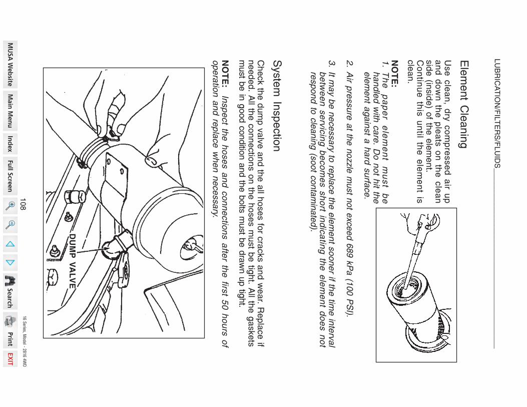
16 S
eries, Model - 2
816 4
WD
Element C
leaning
Use
clean, d
ry compressed
air u
pand
down
the
pleats
on
the
clean
side
(inside) o
f the
element.
Contin
ue
this
until th
e e
lement is
clean.
NO
TE
:
1.
Th
e
pa
pe
r e
lem
en
t m
us
t b
eh
an
dle
d w
ith c
are
. Do
no
t hit th
ee
lem
en
t ag
ain
st a
ha
rd s
urfa
ce
.
2.
Air p
ressu
re a
t the
no
zzle
mu
st n
ot e
xce
ed
68
9 k
Pa
(10
0 P
SI).
3.
It ma
y b
e n
ece
ssa
ry to
rep
lace
the
ele
me
nt s
oo
ne
r if the
time
inte
rva
lb
etw
ee
n s
erv
icin
g b
eco
me
s s
ho
rt ind
ica
ting
the
ele
me
nt d
oe
s n
ot
resp
on
d to
cle
an
ing
(so
ot c
on
tam
ina
ted
).
System
Inspectio
n
Check th
e dump
valve
and
the
all h
oses fo
r cracks and
wear. R
eplace
ifneeded. A
ll the
connectio
ns on
the
hoses m
ust b
e tig
ht. A
ll the
gaskets
must b
e in
good conditio
n and th
e bolts
must b
e drawn up tig
ht.
NO
TE
: In
sp
ect th
e h
ose
s a
nd
co
nn
ectio
ns a
fter th
e firs
t 50
ho
urs
of
op
era
tion
an
d re
pla
ce
wh
en
ne
ce
ssa
ry.
DU
MP
V
AL
VE
10
8
LUBRICATIO
N/FILTERS/FLUIDS
__
__
__
__
__
__
__
__
__
__
__
__
__
__
__
__
__
__
__
__
__
_

16 S
eries, Model - 2
816 4
WD
DIP
ST
ICK
Transmission
Oil L
evel
(Gear D
rive)
To
check
the
tra
nsmission
flu
idlevel, p
ut th
e tra
ctor o
n le
vel g
round.
Unscrew
the
filler c
ap
with
dipstic
kand
wipe
it clean. C
heck le
vel - D
onot s
crew
in cap
when
checking. If
the
fluid
level is
below
the
lower lin
eof th
e dipstic
k, a
dd
the
recommended
fluid
to ra
ise
the
fluid
level to
the
F(Full) m
arke
d positio
n.
Check th
e oil le
vel o
n th
e tra
nsmission
dipstic
k. If th
e oil le
vel is
below
the
lower lin
e of th
e dipstic
k, a
dd
the
recommended
oil to
the
transmis-
sion
to ra
ise
the
oil le
vel to
the
F (F
ull) m
arke
d positio
n.
TRANSMISSIO
N &
HYDRAULIC
LUBRIC
ATIO
N
Service
Specific
atio
ns
Oil L
evel C
heck In
terval.....................................................................D
aily
Oil C
hange
Interval..........................................................E
very
200
hours.
Oil C
apacity
–Hydrostatic
Driv
e.........................2
2 Litre
s (2
3.2
Quarts
).Oil T
ype
– H
ydrostatic
Driv
e.........
Refer L
ubric
atio
n Table
page
88
Hydraulic
System
Check........................Y
early
inspect fo
r leaks, c
racks
and
abrasion. T
ighten
fittings or
replace
as needed.
10
9
LUBRICATIO
N/FILTERS/FLUIDS
__
__
__
__
__
__
__
__
__
__
__
__
__
__
__
__
__
__
__
__
__
_
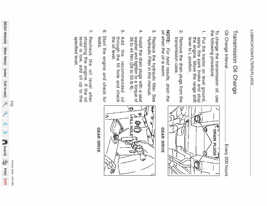
16 S
eries, Model - 2
816 4
WD
Transmission
Oil C
hange
Oil C
hange In
terv
al............................................................
Every
200 h
ours
To
ch
an
ge
the
tran
sm
issio
n o
il, use
the fo
llow
ing p
rocedure
:
1.
Pu
t the
tracto
r on
leve
l gro
un
d,
ap
ply
the
pa
rk b
rake
an
d s
top
the e
ngin
e. M
ove th
e ra
nge s
hift
lever to
L p
ositio
n.
2.
Rem
ove th
e d
rain
plu
gs fro
m th
etra
nsm
issio
n c
ase.
NO
TE
: Fo
r be
st re
su
lts, d
rain
the
oil w
hen th
e o
il is w
arm
.
3.
Re
pla
ce
the
hyd
rau
lic filte
r. Se
eH
ydra
ulic
Filte
r in th
is m
anual.
4.
Insta
ll the d
rain
plu
gs w
ith a
seal
washer a
nd tig
hte
n to
a to
rque o
f39 to
44 N
m (2
9 to
33 lb
ft).
5.
Ad
d
the
re
co
mm
en
de
d
oil
thro
ug
h th
e fill h
ole
an
d c
he
ck
the o
il level.
6. S
tart th
e e
ng
ine
an
d c
he
ck fo
rle
aks.
7.
Re
ch
ec
k
the
o
il le
ve
l a
fter
sto
pp
ing
the
en
gin
e. If th
e o
ille
ve
l is lo
w, a
dd
oil u
p to
the
specifie
d le
vel.
DR
AIN
PL
UG
S
GE
AR
DR
IVE
GE
AR
DR
IVE
FIL
L H
OL
E
11
0
LUBRICATIO
N/FILTERS/FLUIDS
__
__
__
__
__
__
__
__
__
__
__
__
__
__
__
__
__
__
__
__
__
_

16 S
eries, Model - 2
816 4
WD
HY
DR
AU
LIC
FIL
TE
R
CH
AN
GE
TH
E H
YD
RA
UL
IC F
ILT
ER
AS
FO
LL
OW
S:
1.
Pu
t the
tracto
r on
leve
l gro
un
d, m
ove
the
ran
ge
sh
ift leve
r to th
e L
po
sitio
n a
nd
ap
ply th
e p
ark b
rake
.
2.
Pu
t an
oil c
an
iste
r un
de
r the
hyd
rau
lic filte
r.
3.
Tu
rn th
e filte
r co
un
terc
lockw
ise
to re
mo
ve
. Use
a filte
r wre
nch
ifn
ece
ssa
ry.
4.
Ap
ply
clea
n o
il to th
e O
-ring
on
the
ne
w filte
r.
5.
Insta
ll the
filter. T
urn
the
filter u
ntil th
e O
-ring
co
me
s in
co
nta
ct w
ithth
e c
ase
su
rface
. Tig
hte
n th
e filte
r an
ad
ditio
na
l 2/3
turn
by h
an
d.
IMP
OR
TA
NT:
DO
NO
T u
se
a filte
r wre
nch
to in
sta
ll the
hyd
rau
lic filte
r.W
he
n th
e filte
r is to
o tig
ht, y
ou
ca
n c
au
se
da
ma
ge
to th
e O
-ring
an
dfilte
r.
6.
Wip
e a
rou
nd
the
hyd
rau
lic filte
r with
a d
ry c
loth
.
7.
Ch
an
ge
the
tran
sm
issio
n o
il. Se
e T
ran
sm
issio
n O
il Ch
an
ge
in th
ism
an
ua
l.
NO
TE
: R
ep
lace
the
hyd
rau
lic filte
ra
fter th
e firs
t 50
ho
urs
of o
pe
ratio
na
nd
eve
ry 2
00
ho
urs
of o
pe
ratio
nth
ere
afte
r. Y
ou
r D
ea
ler
ha
s a
p-
pro
ve
d g
en
uin
e filte
rs. D
o n
ot u
se
oth
er typ
e filte
rs.
Hydraulic
Filte
r (Hydrostatic
Driv
e)
Change
Interval..................................................
Every
200
hours
(See
NOTE)
111
LUBRICATIO
N/FILTERS/FLUIDS
__
__
__
__
__
__
__
__
__
__
__
__
__
__
__
__
__
__
__
__
__
_

16 S
eries, Model - 2
816 4
WD
Front A
xle
Oil L
evel
To
check th
e fro
nt a
xle
oil le
vel, p
ut
the
tractor o
n le
vel g
round. R
emove
the
oil le
vel p
lugs lo
cated
on
the
rear o
f the
both
gear c
ases. If th
e oil
level is
low, a
dd
the
recommended
oil ty
pe
through
the
fill hole
located
on
the
RH
side
of a
xle
housing
until
the
oil b
egins to
flow
out o
f the
level
plug
holes. FRONT
AXLE
LUBRIC
ATIO
N (M
FD)
Service
Specific
atio
ns
Oil C
hange
Interval.....................................
Every
200
hours
(See
NOTE)
Oil C
apacity
..............................................................4.0
Litre
s (4
.2 Q
uarts
)Oil T
ype.......................................................S
AE
85W-140
Gear L
ubric
ant
NO
TE
: C
ha
ng
e th
e o
il afte
r the
first 5
0 h
ou
rs o
f op
era
tion
an
d th
en
eve
ry 2
00
ho
urs
of o
pe
ratio
n.D
RA
IN P
LU
G
LE
VE
L
PL
UG
LE
VE
L
PL
UG
GR
EA
SE
NIP
PL
E
FIL
L C
AP
OIL
LE
VE
L
PL
UG
11
2
LUBRICATIO
N/FILTERS/FLUIDS
__
__
__
__
__
__
__
__
__
__
__
__
__
__
__
__
__
__
__
__
__
_

16 S
eries, Model - 2
816 4
WD
Front A
xle
Oil C
hange
1.To
change
the
front a
xle
oil, p
ut th
e tra
ctor o
n le
vel g
round. P
ut th
erange
lever in
L, e
ngage
the
park b
rake
and
stop
the
engine.
DR
AIN
PL
UG
DIF
FE
RE
NT
IAL
DR
AIN
PL
UG
FIL
L H
OL
E
2.
Re
mo
ve
the
fill ca
p lo
ca
ted
on
the
axle
ho
usin
g, th
e d
iffere
ntia
ld
rain
plu
g lo
ca
ted
in th
e b
otto
mo
f the
ho
usin
g a
nd
the
ge
ar c
ase
dra
in p
lug
s lo
ca
ted
on
the
bo
t-to
m o
f bo
th s
ide
ge
ar c
ase
s to
dra
in th
e o
il.
NO
TE
: F
or b
est re
su
lts, d
rain
the
oil w
he
n th
e o
il is w
arm
.
3.
Insta
ll the
diffe
ren
tial a
nd
bo
th g
ea
r ca
se
dra
in p
lug
s. R
em
ove
the
oil
leve
l plu
gs lo
ca
ted
on
bo
th g
ea
r ca
se
s. A
dd
the
reco
mm
en
de
d o
ilth
rou
gh
the
fill ho
le u
ntil th
e o
il be
gin
s to
flow
ou
t of th
e le
ve
l plu
gh
ole
s. In
sta
ll the
oil le
ve
l plu
gs a
nd
the
fill ca
p.
11
3
LUBRICATIO
N/FILTERS/FLUIDS
__
__
__
__
__
__
__
__
__
__
__
__
__
__
__
__
__
__
__
__
__
_

16 S
eries, Model - 2
816 4
WD
COOLIN
G S
YSTEM
Grille
Screens and
Radiator A
rea
Grille
Screens and
Radiator A
rea
Service
Interval..................E
very
50
hours
or m
ore
frequently
if require
d.
To
clean
the
radiator s
creen, p
ut th
e tra
ctor o
n le
vel g
round, a
pply
the
park
brake
and
stop
the
engine.
Lift a
nd
Lo
ck th
e h
oo
d.
Lift th
e ra
dia
tor s
cre
en
.
ST
EP
3
Cle
an
the
rad
iato
r scre
en
an
d th
esu
rrou
nd
ing
are
a.
ST
EP
4
Insta
ll the
rad
iato
r scre
en
.L
ow
er th
e h
oo
d.
RA
DIA
TO
R
SC
RE
EN
ST
EP
2
ST
EP
1
11
4
MAINTENANCE/ADJUSTMENTS
__
__
__
__
__
__
__
__
__
__
__
__
__
__
__
__
__
__
__
__
__
_

16 S
eries, Model - 2
816 4
WD
Fan
Belt A
djustm
ent
Fan
Belt T
ension
Check In
terval ............................ D
aily
or a
fter 1
0 H
ours
NO
TE
: A
dju
st th
e b
elt te
nsio
n a
fter th
e firs
t 50
ho
urs
of o
pe
ratio
n a
nd
rep
lace
wh
en
ne
ce
ssa
ry.
Me
asu
re th
e fa
n b
elt fo
r co
rrect te
nsio
n. C
he
ck to
se
e if th
e b
elt
de
flectio
n is
ab
ou
t 13
mm
(0.5
inch
) wh
en
pu
sh
ing
the
be
lt with
10
kg
(22
lb) lo
ad
at p
oin
t �
.
To
Ad
just th
e fa
n b
elt te
nsio
n lo
ose
n th
e a
dju
stin
g b
olt a
nd
piv
ot n
ut o
fth
e a
ltern
ato
r. Mo
ve
the
alte
rna
tor a
wa
y fro
m th
e e
ng
ine
un
til co
rrect b
elt
ten
sio
n is
rea
ch
ed
. Tig
hte
n th
e a
dju
stin
g b
olt a
nd
piv
ot n
ut to
a to
rqu
e o
f16
Nm
(12
lb ft).
NO
TE
: To
o m
uch
ten
sio
n w
ill ca
use
alte
rna
tor a
nd
wa
ter p
um
p b
ea
ring
failu
re a
nd
be
lt we
ar. T
oo
little te
nsio
n w
ill ca
use
a d
ecre
ase
in a
ltern
ato
ro
utp
ut a
nd
be
lt we
ar.
Ro
tatin
g fa
n a
nd
belts
. Co
nta
ct c
an
inju
re. K
eep
cle
ar.
M150
PIV
OT
NU
T
AD
JU
ST
ING
BO
LT
11
5
MAINTENANCE/ADJUSTMENTS
__
__
__
__
__
__
__
__
__
__
__
__
__
__
__
__
__
__
__
__
__
_

16 S
eries, Model - 2
816 4
WD
Fan
Belt R
eplacement
To re
place th
e fa
n belt, u
se fo
llowing procedure:
Ra
ise
the
ho
od
. Re
mo
ve
the
LH
sid
e c
ove
r.
Lo
ose
n th
e a
ltern
ato
r ad
justin
gb
olt.
Insta
ll ne
w fa
n b
elt a
nd
ad
just th
eb
elt te
nsio
n. S
ee
Fa
n B
elt A
dju
st-
me
nt in
this
ma
nu
al fo
r instru
c-
tion
s.
Lo
ose
n th
e a
ltern
ato
r piv
ot n
ut
an
d p
ush
the
alte
rna
tor to
wa
rdth
e e
ng
ine
to re
mo
ve
the
be
lt.
ST
EP
1L
.H. S
IDE
CO
VE
RS
TE
P 3
PIV
OT
NU
T
ST
EP
2A
DJ
US
TIN
G B
OLT
ST
EP
4
11
6
MAINTENANCE/ADJUSTMENTS
__
__
__
__
__
__
__
__
__
__
__
__
__
__
__
__
__
__
__
__
__
_

16 S
eries, Model - 2
816 4
WD
CL
UT
CH
RO
D
CL
UT
CH
AR
M
AD
JU
ST
ING
NU
TS
CLUTCH
PEDAL
ADJUSTMENT
Service
Specific
atio
ns
Clutch
Pedal C
heck and
Adjustm
ent In
terval.........
Every
200
hours
of o
p-
eratio
n or y
early
Free
Pedal M
ovement...................................2
0 –
30
mm
(0.8
– 1.2
inch)
Max. P
edal M
ovement
Dual C
lutch........................................1
25–130
mm
(4.9
– 5.1
inch)
Free
Movement A
djustm
ent
Clutch
pedal fre
e m
ovement is
very
importa
nt a
nd
must b
e checked
at
the
recommended
intervals. If th
ere
is no
free
movement, th
e clutch
disc
will w
ear q
uickly. If th
ere
is to
o m
uch
free
movement, th
e clutch
will n
ot
disengage
corre
ctly
and
the
transmission
will b
e diffic
ult to
shift.
Put the
tra
ctor on
level gro
und,
move
the
range
shift le
ver in
the
Lpositio
n, a
pply
the
park
brake, s
top
the
engine
and
adjust th
e c
lutch
pedal fre
e m
ovement a
s fo
llows:
Push
the
clutch
pedal down
by
hand, to
measure
the
amount o
fpedal fre
e m
ovement.
The
pedal fre
e m
ovement m
ust b
ewith
in th
e specific
atio
n shown
above.
Adjust th
e pedal fre
e m
ovement a
snecessary
with
the
adjustin
g nuts
on
the
clutch
rod.
To
increase
free
movement, tu
rn th
enuts
in.
To
decrease
free
movement, tu
rnthe
nuts
out. T
ighten
the
nuts
to a
torque
of 4
4 to
54
Nm
(32
to 40
lbft).
11
7
MAINTENANCE/ADJUSTMENTS
__
__
__
__
__
__
__
__
__
__
__
__
__
__
__
__
__
__
__
__
__
_

16 S
eries, Model - 2
816 4
WD
Maxim
um
Pedal M
ovement A
djustm
ent
The
Maxim
um
Pedal M
ovement is
very
importa
nt a
nd
must b
e checked
at th
e re
commended
intervals. If th
ere
is to
o little
movement, th
e clutch
can
disengage. If th
ere
is to
o m
uch
movement, th
e clutch
component
parts
can
be
damaged.
NO
TE
: A
dju
st th
e M
axim
um
Pe
da
l Mo
ve
me
nt a
fter a
dju
stin
g th
e F
ree
Mo
ve
me
nt.
Pu
t the
tracto
r on
leve
l gro
un
d, m
ove
the
ran
ge
sh
ift leve
r in th
e L
po
sitio
n, a
pp
ly th
e p
ark
bra
ke
, sto
p th
e e
ng
ine
an
d a
dju
st th
e c
lutc
hp
ed
al m
axim
um
mo
ve
me
nt a
s fo
llow
s:
Pu
sh
the
clu
tch
pe
da
l do
wn
by h
an
dto
elim
ina
te th
e p
ed
al fre
e m
ove
-m
en
t.
Me
asu
re th
e d
ista
nce
be
twe
en
the
sto
p b
olt a
nd
the
clu
tch
pe
da
l arm
.T
he
Ma
xim
um
Pe
da
l Mo
ve
me
nt
mu
st b
e w
ithin
the
sp
ec
ifica
tion
ssh
ow
n o
n th
e p
revio
us p
ag
e.
Ad
just th
e M
axim
um
Pe
da
l Mo
ve
-m
en
t as n
ece
ssa
ry w
ith th
e s
top
bo
lt.
To
incre
ase
Ma
xim
um
Pe
da
l Mo
ve
-m
en
t – L
oo
se
n th
e lo
ck n
ut a
nd
turn
the
stop
bo
lt in.
To
de
cre
ase
Ma
xim
um
Pe
da
l Mo
ve
-m
en
t – L
oo
se
n th
e lo
ck n
ut a
nd
turn
the
sto
p b
olt o
ut.
ST
OP
B
OLT
LO
CK
N
UT
CL
UT
CH
AR
M
11
8
MAINTENANCE/ADJUSTMENTS
__
__
__
__
__
__
__
__
__
__
__
__
__
__
__
__
__
__
__
__
__
_

16 S
eries, Model - 2
816 4
WD
BRAKE
PEDAL
ADJUSTMENT
Service
Specific
atio
ns
Brake
Pedal C
heck and
Adjustm
ent In
terval...
Every
200
hours
or y
early
Free
Pedal M
ovement S
pecific
atio
n..................................
25
mm
(1 in
ch)
Brake
pedal fre
e p
lay is
very
importa
nt a
nd
must b
e checked
at th
erecommended
intervals. If th
ere
is no
free
movement, th
e brake
shoes
will w
ear q
uickly.
If there
is to
o m
uch
free
movement, a
ccidents
may occur. If th
ere
is not
the
same
free
movement b
etw
een
LH
pedal a
nd
RH
pedal, it m
ay cause
serio
us accidents.
Put th
e tra
ctor o
n le
vel g
round, m
ove
the
range
lever in
the
L positio
n.
Stop
the
engine.
Loosen
lock
nut and
ro
tate
the
brake
rod
to m
ake
a fre
e play of 2
0to
30
mm
(0.79
to 1
.18
in.) a
t the
brake
pedal.
With
this
much
play
obtained,
tighten
the
lock nut.
Confirm
that th
e rig
ht a
nd
left b
rakes
operate
sim
ulta
neously
by ru
nning
the
tractor.
If not, a
djust b
oth
of th
em
by m
eans
of th
e brake
rods.
BR
AK
E R
OD
LO
CK
NU
T
FR
EE
MO
VE
ME
NT
11
9
MAINTENANCE/ADJUSTMENTS
__
__
__
__
__
__
__
__
__
__
__
__
__
__
__
__
__
__
__
__
__
_
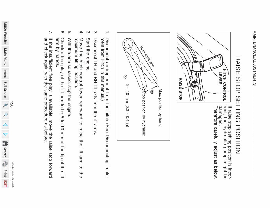
16 S
eries, Model - 2
816 4
WD
1.
Dis
co
nn
ect a
n im
ple
me
nt fro
m th
e h
itch
(Se
e D
isco
nn
ectin
g Im
ple
-m
ent fro
m H
itch in
this m
anual.)
2.
Disco
nnect L
H a
nd R
H lift ro
ds fro
m th
e lift a
rms.
3.
Sta
rt the
en
gin
e.
4.
Mo
ve
the
hitc
h c
on
trol le
ve
r rea
rwa
rd to
rais
e th
e lift a
rm to
the
ma
xim
um
lifting
po
sitio
n.
5.
With
the a
rm so
raise
d, sto
p th
e e
ngin
e.
6.
Ch
eck a
free
pla
y o
f the
lift arm
to b
e 5
to 1
0 m
m a
t the
tip o
f the
lifta
rm b
y h
an
ds.
7.
If the
insu
fficie
nt fre
e p
lay is
ava
ilab
le, m
ove
the
rais
e s
top
forw
ard
an
d c
he
ck a
ga
in w
ith th
e s
am
e p
roce
du
re a
s b
efo
re.
If rais
e s
top
se
tting
po
sitio
n is
inco
r-re
ct, th
e h
yd
rau
lic p
um
p m
igh
t be
da
ma
ge
d.
Th
ere
fore
ca
refu
lly a
dju
st a
s b
elo
w.
RAISE
STOP
SETTIN
G P
OSITIO
N
HIT
CH
CO
NT
RO
L L
EV
ER
5 ~
10
mm
(0.2
~ 0
.4 in
)
Sto
p p
ositio
n b
y h
yd
rau
lic
Ma
x. p
ositio
n b
y h
an
d
Ram
shaft a
rm
RA
ISE
S
TO
P
12
0
MAINTENANCE/ADJUSTMENTS
__
__
__
__
__
__
__
__
__
__
__
__
__
__
__
__
__
__
__
__
__
_

16 S
eries, Model - 2
816 4
WD
Electric
al S
ystem
Type
of S
ystem
...................................................12
Volt, N
egativ
e G
round
Batte
ry................................................................
EX
IED
58
-60
12
V-5
40
CC
A
9-13/
16 L
; 7-13/
16 W
; 7H
SA
E T
AP
ER
Alte
rna
tor
...........................................................12
Vo
lt, 50
Am
pe
re O
utp
ut
Vo
ltag
e R
eg
ula
tor........................................................IC
Bu
ilt in A
ltern
ato
r
Sta
rter M
oto
r............................1
2 V
olt, 1
.6 k
W w
ith S
ole
no
id S
witc
h
He
ad
La
mp
.......................................................................................35
wa
tt
Fla
sh
er L
am
p..................................................................................
32
wa
tt
Re
ar R
ed
La
mp
................................................................................8
wa
tt
Re
ar W
ork
ing
La
mp
(If Eq
uip
pe
d)
.................................................2
3 w
att
Pa
ne
l La
mp
.....................................................................................3.4
wa
tt
Tu
rn In
dic
ato
r La
mp
.......................................................................2.0
wa
tt
Ind
ica
tor L
am
p...............................................................................2
.0 w
att
Fuses
Glove
indicator la
mp..................................................................................1
0 Amp
Charge
indicator la
mp, E
ngine
oil p
ressure
indicator la
mp...................1
0 A
mp
Engine
Coolant T
emperature
Gauge, F
uel G
auge, F
uel P
ump
Head
lamps, R
ear R
ed
Lamp, H
igh
Beam
indicator la
mp....................
15 A
mp
Instru
ment P
anel L
amps
Turn
signal la
mps......................................................................................1
5 Amp
Other o
ptio
nal e
lectric
al e
quipments........................................................1
5 Amp
SPECIFIC
ATIO
NS
12
1
EL
EC
TR
ICA
L S
YS
TE
M_
__
__
__
__
__
__
__
__
__
__
__
__
__
__
__
__
__
__
__
__
__
__
__
__

16 S
eries, Model - 2
816 4
WD
GENERAL S
ERVIC
E IN
FORMATIO
N
Alte
rnator C
harging
System
Follo
w th
ese
general ru
les to
prevent d
amage
to th
e electric
al s
ystem:
1.
Before
working
on
the
electric
al s
ystem, d
isconnect th
e b
atte
rycables.
2.
Do
not m
ake
a re
verse
batte
ry connectio
n.
3.
When
you
use
an
auxilia
ry batte
ry fo
r startin
g, c
onnect p
ositiv
e to
positiv
e and
negativ
e on
the
auxilia
ry batte
ry to
the
tractor s
ide
rail a
sa
ground.
4.
When
charging
the
tractor b
atte
ry, disconnect th
e batte
ry cables fro
mthe
batte
ry te
rminals. D
o n
ot u
se
a b
atte
ry charging
machine
for
startin
g th
e tra
ctor.
5.
Never o
perate
the
tractor w
hen
the
batte
ry cables are
disconnected.
6.
When
you
do
maintenance
on
the
engine, p
revent fo
reign
materia
lfro
m enterin
g th
e alte
rnator.
7.
If you
must d
o w
elding, d
isconnect th
e batte
ry. Put th
e w
elder g
round
cable
as close
as you
can
to th
e w
eld
area. D
o not p
ut th
e ground
cable
where
the
curre
nt c
an
flow
through
bearin
gs or a
long
channels
with
wire
harnesses.
12
2
EL
EC
TR
ICA
L S
YS
TE
M_
__
__
__
__
__
__
__
__
__
__
__
__
__
__
__
__
__
__
__
__
__
__
__
__

16 S
eries, Model - 2
816 4
WD
Ca
rtridg
e ty
pe
fuse
s a
re u
se
d fo
r he
ad
lam
ps, re
ar re
d la
mp
, instru
me
nt
lam
ps, tu
rn s
ign
al a
nd
flash
er la
mp
s, a
nd
rea
r wo
rk la
mp
(if eq
uip
pe
d).
Th
e fu
ses a
re lo
cate
d in
the
fuse
blo
ck, R.H
. rea
r of e
ng
ine
roo
m.
If a s
ho
rt circ
uit o
ccu
rs, th
e fu
se
will b
urn
ou
t an
d b
rea
k th
e c
ircu
it,p
reve
ntin
g d
am
ag
e to
the
ele
ctrical syste
m.
Fu
se A
(10
AM
P) is fo
r the
glo
w p
lug
ind
icato
r lam
ps.
Fu
se
B (1
0 A
MP
) is fo
r the
ch
arg
e in
dic
ato
r lam
p, e
ng
ine
oil p
ressu
re in
dic
a-
tor la
mp
, en
gin
e co
ola
nt te
mp
era
ture
ga
ug
e, fu
el g
au
ge
an
d fu
el p
um
p.
Fu
se C
(10
AM
P) is fo
r the
hig
h b
ea
m in
dica
tor la
mp
, instru
me
nt p
an
el la
mp
s,
he
ad
lam
ps a
nd
rea
r red
lam
p.
Fu
se
D (1
5 A
MP
) is for th
e tu
rn sig
na
l lam
ps.
Fu
se
E (1
5 A
MP
) is for th
e o
ptio
na
l ele
ctrical e
qu
ipm
en
ts.
Fuses
12
3
EL
EC
TR
ICA
L S
YS
TE
M_
__
__
__
__
__
__
__
__
__
__
__
__
__
__
__
__
__
__
__
__
__
__
__
__

16 S
eries, Model - 2
816 4
WD
FU
SIB
LE
LIN
K
LIN
E F
US
E
Tw
oL
ine
fuse
s a
re in
sta
lled
an
d th
e c
ircu
it ca
n b
e id
en
tified
by c
olo
r of b
ox.
Re
d B
ox
(50
AM
P):S
ole
no
id s
witc
h circu
it
Ye
llow
Bo
x(6
0A
MP
):Wirin
g h
arn
ess a
nd
alte
rna
tor c
ha
rgin
g s
yste
m
Line
Fuse
If the
electric
al c
ircuit is
accidently
grounded
or a
reverse
batte
ry connectio
nis
made, th
e Line
fuse
located
on
the
LH
side
of th
e engine
will b
urn
out a
nd
break th
e circ
uit to
prevent th
e solenoid
switch, w
iring
harness and
alte
rnator c
harg-
ing
system
from
being
damaged. If e
lectric
al p
roblems
occur, th
e L
ine
fuse
must b
e checked
for c
ontin
uity
to d
eterm
ine
if one
of th
e circ
uits
isbroken, s
ee
your D
ealer to
replace
and
corre
ct.
12
4
EL
EC
TR
ICA
L S
YS
TE
M_
__
__
__
__
__
__
__
__
__
__
__
__
__
__
__
__
__
__
__
__
__
__
__
__

16 S
eries, Model - 2
816 4
WD
Auxilia
ry B
atte
ry C
onnectio
ns
IMP
OR
TA
NT:
Alw
ays c
on
ne
ct th
e n
eg
ativ
e c
ab
le la
st a
nd
dis
co
nn
ect
the
ne
ga
tive
ca
ble
first s
o y
ou
do
no
t ca
use
a s
pa
rk a
t the
ba
ttery. A
sp
ark
ca
n c
au
se
a b
atte
ry e
xp
losio
n a
nd
ca
use
inju
ry.
Co
nn
ect th
e n
eg
ativ
e (–
) ca
ble
cla
mp
of th
e a
uxilia
ry b
atte
ry to
the
tracto
r sid
e ra
il as a
gro
un
d.
Co
nn
ect th
e p
ositiv
e (+
) ca
ble
cla
mp
of th
e a
uxilia
ry b
atte
ry to
the
po
sitiv
e c
ab
le te
rmin
al o
f the
tracto
r ba
ttery.
Wh
en
co
nn
ectin
g a
n a
uxilia
ry b
atte
ry o
r ch
arg
er to
the
tracto
r ba
ttery,
ma
ke
su
re y
ou
co
nn
ect p
ositiv
e to
po
sitiv
e a
nd
ne
ga
tive
on
the
au
xilia
ryb
atte
ry to
the
tracto
r sid
e ra
il as a
gro
un
d. D
o n
ot c
on
ne
ct a
uxilia
ryb
atte
ry c
ab
les a
cro
ss th
e te
rmin
als
of th
e s
tarte
r. Sta
rt the
en
gin
e fro
mth
e o
pe
rato
r’s s
ea
t.
PO
SIT
IVE
( + )
NE
GA
TIV
E ( –
)
IMP
OR
TA
NT:
Th
is is
the
on
ly s
afe
me
tho
d to
sta
rt the
tracto
r en
gin
ew
ith a
n e
xte
rna
l po
we
r su
pp
ly. An
y o
the
r me
tho
d o
f sta
rting
ca
n c
au
se
inju
ry o
r de
ath
to th
e o
pe
rato
r or o
the
r pe
rson
s.
En
gin
e c
an
sta
rt with
tran
sm
issio
n in
gear w
hen
neu
tral o
r safe
tysta
rt sw
itch
is b
y-p
assed
:1.
Do
no
t co
nn
ect a
cro
ss te
rmin
als
on
sta
rter.
2.
Atta
ch
a b
oo
ste
r batte
ry b
y c
on
nectin
g th
e p
ositiv
e te
rmin
al o
fth
e b
oo
ste
r batte
ry to
the “
po
sitiv
e te
rmin
al”
pro
vid
ed
or to
the
po
sitiv
e te
rmin
al o
f the m
ach
ine b
atte
ry. Co
nn
ect th
e n
eg
ativ
e te
r-m
inal o
f the b
oo
ste
r batte
ry to
the “
neg
ativ
e te
rmin
al”
pro
vid
ed
or
to th
e c
hassis
of th
e m
ach
ine.
Th
en
use re
co
mm
en
ded
sta
rting
pro
ced
ure
s fro
m o
pera
tors
seat.
3. W
hen
necessary, re
pair e
lectric
al s
yste
m c
om
po
nen
ts p
rom
ptly
so
that “
jum
p s
tartin
g” w
ill no
t be a
ttem
pte
d.
Mach
ine ru
n-a
way c
an
cau
se in
jury
or d
eath
to o
pera
tor a
nd
bysta
n-
ders
.M107C
BATTERY
TE
RM
INA
L
12
5
EL
EC
TR
ICA
L S
YS
TE
M_
__
__
__
__
__
__
__
__
__
__
__
__
__
__
__
__
__
__
__
__
__
__
__
__

16 S
eries, Model - 2
816 4
WD
Batte
ry C
ables and
Term
inals
The
batte
ry te
rminals
must b
e kept
clean
and
tight. A
good
method
toclean
term
inals
is to
use
Batte
rySaver.
If Saver is
not availa
ble,
remove
all c
orro
sion
with
a w
irebru
sh,
then
wash
with
a
weak
solutio
n of b
aking
soda
or a
mmonia.
Put s
ome
petro
leum
jelly
or lig
ht
gre
ase
on
term
inals
to
pre
vent
corro
sion.
Removal a
nd
Installa
tion
of B
atte
ry
To
remove
the
batte
ry d
isconnect th
e b
atte
ry cables a
nd
remove
the
batte
ry bracket. W
hen
the
batte
ry is
installe
d, m
ake
sure
the
cables are
installe
d o
n th
e corre
ct te
rminals. T
his
is a
12
volt, n
egativ
e g
round
electric
al s
ystem
and
must b
e so
connected.
NO
TE
: Wh
en
dis
co
nn
ectin
g th
e b
atte
ry, rem
ove
the
ne
ga
tive
ca
ble
first
from
the
ba
ttery
an
d re
co
nn
ect it la
st fo
r sa
fety
rea
so
ns.
IMP
OR
TA
NT:
Do
no
t sta
rt or o
pe
rate
the
en
gin
e w
ith th
e e
lectric
al
syste
m n
ot c
om
ple
tely
co
nn
ecte
d.
WARNIN
G
321-6714
BA
TT
ER
IES
CO
NTA
IN A
CID
AN
D E
XP
LO
SIV
EG
AS
. E
XP
LO
SIO
N
CA
N
RE
SU
LT
F
RO
MS
PA
RK
S, F
LA
ME
S, O
R W
RO
NG
CA
BL
E C
ON
-N
EC
TIO
NS
, TO
CO
NN
EC
T J
UM
PE
R C
AB
LE
SO
R C
HA
RG
ER
, SE
E M
AN
UA
L(S
) FO
R T
HE
CO
RR
EC
T
PR
OC
ED
UR
E.
FA
ILU
RE
T
OF
OL
LO
W T
HE
AB
OV
E IN
ST
RU
CT
ION
S C
AN
CA
US
E S
ER
IOU
S P
ER
SO
NA
L IN
JU
RY
OR
DE
AT
H.
12
6
EL
EC
TR
ICA
L S
YS
TE
M_
__
__
__
__
__
__
__
__
__
__
__
__
__
__
__
__
__
__
__
__
__
__
__
__

16 S
eries, Model - 2
816 4
WD
When
Charging
the
Batte
ry
IMP
OR
TA
NT:
Ba
ttery
ca
n e
xp
lod
e d
urin
g b
oo
stin
g o
r ch
arg
ing
. Alw
ays
we
ar p
rop
er e
ye
pro
tectio
n, s
uch
as a
sa
fety
go
gg
les.
If the
ele
ctric
circ
uit in
sid
e th
e b
atte
ry is
bro
ke
n, c
ha
rgin
g c
an
ge
ne
rate
asp
ark
insid
e th
e b
atte
ry w
hic
h c
an
ca
use
it to e
xp
lod
e.
If the
ba
ttery
is d
isch
arg
ed
, an
d th
e re
aso
n fo
r dis
ch
arg
e is
un
kn
ow
n a
nd
if the
lam
ps o
r ho
rn d
o n
ot in
dic
ate
so
me
ba
ttery
vo
ltag
e, c
he
ck th
eb
atte
ry w
ith a
vo
lt me
ter fo
r an
op
en
circuit u
sing
follo
win
g p
roce
du
re.
1.
Dis
co
nn
ect th
e n
eg
ativ
e ( –
) ca
ble
.2
.C
on
ne
ct th
e v
olt m
ete
r acro
ss b
atte
ry te
rmin
als
.3
.If th
ere
is n
o v
olta
ge
pre
se
nt, a
n o
pe
n in
tern
al c
ircu
it is in
dic
ate
d.
Re
pla
ce
the
ba
ttery.
4.
If vo
ltag
e is
pre
se
nt, th
e b
atte
ry is
OK
to c
ha
rge
. Ch
arg
e th
e b
atte
ryw
ith a
cu
rren
t of 4
am
pe
res fo
r 5 to
10
ho
urs
. To
ch
arg
e th
e b
atte
ryq
uic
kly
for u
rge
nt n
ee
d, u
se
a c
urre
nt o
f 25
am
pe
res fo
r 30
min
ute
so
r less. A
cu
rren
t larg
er th
an
sp
ecifie
d w
ill ca
use
liqu
id o
ve
rflow
du
eto
foa
min
g.
5.
Th
e s
pe
cific
gra
vity
of e
lectro
lyte
of a
fully
ch
arg
ed
ba
ttery
is 1
.28
0 a
t20oC
(68oF
).
NO
TE
:
1.
If usin
g a
ba
ttery
ch
arg
er, b
e c
erta
in th
e c
ha
rge
r is tu
rne
d o
ff be
fore
con
ne
ctin
g to
the
ba
ttery.
2.
Ch
arg
e th
e b
atte
ry in
a w
ell v
en
tilate
d a
rea
.3
.D
o n
ot a
ttem
pt to
ch
arg
e a
froze
n b
atte
ry.
When
Batte
ry is
Not in
Use
When
the
tractor is
not in
use, th
e batte
ry w
ill need
a charge
every
three
months to
keep
the
specific
gravity
at o
r above
1.240. A
storage
batte
rynot in
use
will s
lowly
discharge. A
batte
ry th
at h
as discharged
can
freeze
at lo
w ambient te
mperature
and
cause
damage
to th
e batte
ry and
tractor.
Wh
en
wo
rkin
g a
rou
nd
sto
rag
e b
atte
ries, re
mem
ber th
at a
ll of th
eexp
osed
meta
l parts
are
“liv
e”. N
ever la
y a
meta
l ob
ject a
cro
ss th
ete
rmin
als
becau
se a
sp
ark
or s
ho
rt circ
uit m
ay re
su
lt.M145
12
7
EL
EC
TR
ICA
L S
YS
TE
M_
__
__
__
__
__
__
__
__
__
__
__
__
__
__
__
__
__
__
__
__
__
__
__
__

16 S
eries, Model - 2
816 4
WD
Head
Lamp
Adjustm
ent
NO
TE
: T
o k
ee
p m
axim
um
gro
un
d a
nd
roa
d illu
min
atio
n, c
he
ck a
nd
ad
just th
e h
ea
d la
mp
s fro
m tim
e to
time
. Tire
we
ar a
nd
diffe
ren
t tire s
ize
sw
ill ch
an
ge
the
se
tting
.
Th
e h
ea
d la
mp
s c
an
be
ad
juste
d to
va
riou
s p
ositio
ns b
y a
dju
stin
g th
em
ou
ntin
g s
cre
ws in
the
rea
r of th
e h
ea
d la
mp
un
it.
1.
Pu
t the
tracto
r on
leve
l gro
un
d n
ea
r a w
all w
ith th
e fro
nt e
nd
to th
ew
all a
nd
the
he
ad
lam
ps 6
.1 m
(20
fee
t) from
the
wa
ll.
2.
Me
asu
re th
e d
ista
nce
from
the
gro
un
d to
the
ce
nte
r of th
e h
ea
d la
mp
and
pu
t this d
ime
nsio
n o
n th
e w
all in
the
form
of a
ho
rizon
tal lin
e.
3.
Pu
t a s
eco
nd
ho
rizo
nta
l line
on
the
wa
ll 40
5 m
m (1
6 in
ch
es) lo
we
rth
an
the
first lin
e. T
he
ce
nte
r of th
e lo
w h
ea
d la
mp
be
am
s m
ust b
e o
nth
e s
eco
nd
ho
rizo
nta
l line
, 40
5 m
m (1
6 in
ch
es) b
elo
w th
e firs
th
oriz
on
tal lin
e. A
dju
st th
e h
ea
d la
mp
s u
p o
r do
wn
as n
ee
de
d.
NO
TE
: S
om
e c
ou
ntrie
s h
av
e d
iffere
nt re
gu
latio
ns
for h
ea
d la
mp
alig
nm
en
t an
d o
pe
ratio
n o
n a
roa
d. C
he
ck y
ou
r loca
l reg
ula
tion
s.
CE
NT
ER
OF
HE
AD
LA
MP
BE
AM
20
’ (6.1
m)
16
” (4
05
mm
)
16
” (4
05
mm
)
MA
RK
D
ISTA
NC
E O
F C
EN
TE
R O
F
HE
AD
L
AM
P F
RO
M G
RO
UN
D
12
8
EL
EC
TR
ICA
L S
YS
TE
M_
__
__
__
__
__
__
__
__
__
__
__
__
__
__
__
__
__
__
__
__
__
__
__
__

16 S
eries, Model - 2
816 4
WD
CL
UT
CH
LO
CK
LA
TC
H
STORIN
G T
HE
TRACTOR
When
your tra
ctor is
not to
be
used
for s
ome
time, it s
hould
be
stored
ina
dry
and
protected
place. L
eaving
your tra
ctor o
utdoors, e
xposed
to th
eelements, w
ill shorte
n its
life. F
ollo
w th
e procedure
outlin
ed
below
when
your tra
ctor is
placed
in storage
for p
erio
ds u
p to
approxim
ately
six
months. S
ee
your D
ealer fo
r the
procedure
on
longer s
torage
perio
ds.
A.Store
the
tractor s
o th
e tire
s are
protected
from
light. B
efore
storin
gthe
tractor, c
lean
the
tires th
oroughly, J
ack up
the
tractor, w
hen
it is to
be
out o
f service
for a
long
perio
d. If n
ot ja
cked
up, in
flate
the
tires at
regular in
tervals.
B.Run
the
engine
long
enough
to th
oroughly
warm
the
oil in
the
crankcase, th
en
drain
the
oil. C
hange
the
oil filte
r as in
stru
cted
inEngine
Oil F
ilter. R
efill th
e crankcase
with
a new
oil a
s specifie
d in
Engine
Oil S
electio
n in
this
manual a
nd
run
the
engine
for fiv
eminutes.
C.Fill th
e fu
el ta
nk w
ith a
good
grade
of N
umber T
wo
diesel e
ngine
fuel.
If this
grade
has not b
een
used
regularly, d
rain
the
fuel a
nd
refill. R
un
the
engine
for a
bout fiv
e m
inutes to
circ
ulate
the
fuel th
rough
the
injectio
n system.
D.Drain, flu
sh
and
fill the
coolin
g system
with
an
antifre
eze
mixture
ratio
to p
rotect th
e e
ngine
to th
e lo
west a
ntic
ipated
temperature
or a
minim
um
of 5
0%
antifre
eze
and
add
coolin
g system
conditio
ner. S
ee
COOLIN
G S
YSTEM
in th
is m
anual.
E.Do
not re
move
the
batte
ry fro
m th
e tra
ctor, e
xcept fo
r prolonged
storage
at b
elow
freezing
temperature. T
he
batte
ry should
be
fully
charged
to prevent fre
ezing
of e
lectro
lyte. D
isconnect th
e negativ
eground
cable
at th
e batte
ry to
prevent p
ossible
discharge.
F.
Clutch
assembly
may b
ecome
bound
together if a
tractor is
not
used
for a
n e
xtended
perio
d o
ftim
e. A
clutch
lock la
tch
is pro-
vided
on
your tra
ctor to
lock th
eclutch
in th
e disengaged
positio
nand
should
be
used
to p
revent
this
conditio
n if y
our tra
ctor is
not
used
for a
n e
xtended
perio
d o
ftim
e.
12
9
ST
OR
AG
E_____________________________________________________________

16 S
eries, Model - 2
816 4
WD
REMOVING
FROM
STORAGE
Be
sure
that th
e grade
of o
il in th
e engine
crankcase
is as specifie
d in
Engine
Oil S
electio
n in
this
manual.
A.Loosen
the
fuel ta
nk drain
plug
and
fuel filte
r cup, a
nd
be
sure
all
water a
nd
sedim
ent h
as drained
from
the
fuel s
ystem
before
closing.
Tighten
the
drain
plug
and
replace
the
filter c
up.
B.Check th
e le
vel o
f the
coolant in
the
radiator.
C.Check engine
oil le
vel.
D.Check hydraulic
fluid
level.
E.See
that th
e batte
ry is
fully
charged
and
that th
e te
rminal c
onnectio
ns
are
clamped
tightly.
F.
On
hydrostatic
driv
e tra
ctors, fo
llow
the
same
procedure
for s
tartin
g as
Startin
g Procedure
for H
ydrostatic
Driv
e Tractors
afte
r Transportin
g on
Truck or fla
t car in
this
manual.
G.Start th
e engine
and
let it ru
n slowly.
IMP
OR
TA
NT: K
ee
p th
e d
oo
rs w
ide
op
en
an
d m
ove
the
ma
ch
ine
ou
tsid
eo
f the
sto
rag
e ro
om
imm
ed
iate
ly to
avo
id d
an
ge
r from
exh
au
st fu
me
s. D
on
ot a
cce
lera
te th
e e
ng
ine
rap
idly
or o
pe
rate
it at h
igh
sp
ee
d im
me
dia
tely
afte
r sta
rting
.
NOTE:
Ma
hin
dra
Tra
cto
rs
ST
OR
AG
E_____________________________________________________________
13
0