OPERATOR AND SERVICE MANUAL OM/SM-TDH-CE
31
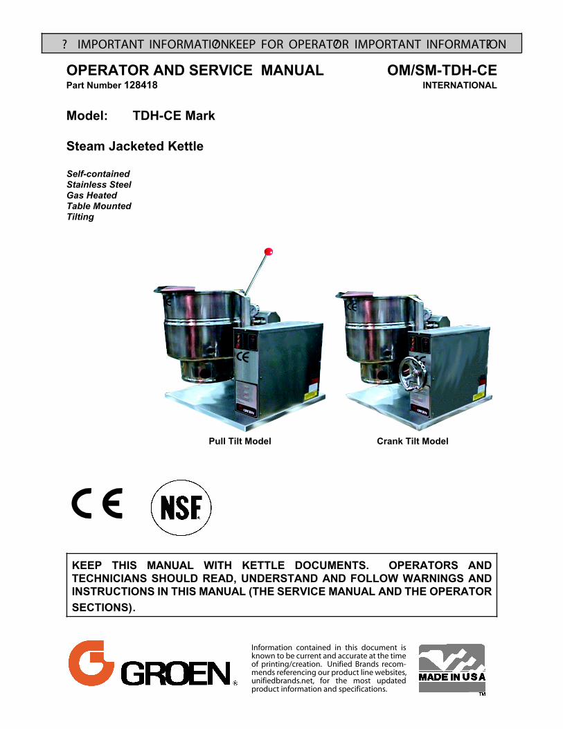
? IMPORTANT INFORMATION ? KEEP FOR OPERATOR ? IMPORTANT INFORMATION ? Pull Tilt Model Crank Tilt Model OPERATOR AND SERVICE MANUAL OM/SM-TDH-CE Part Number 128418 INTERNATIONAL Model: TDH-CE Mark Steam Jacketed Kettle Self-contained Stainless Steel Gas Heated Table Mounted Tilting KEEP THIS MANUAL WITH KETTLE DOCUMENTS. OPERATORS AND TECHNICIANS SHOULD READ, UNDERSTAND AND FOLLOW WARNINGS AND INSTRUCTIONS IN THIS MANUAL (THE SERVICE MANUAL AND THE OPERATOR SECTIONS). Information contained in this document is known to be current and accurate at the time of printing/creation. Unified Brands recom- mends referencing our product line websites, unifiedbrands.net, for the most updated product information and specifications.
-
Upload
hoanghuong -
Category
Documents
-
view
236 -
download
1
Transcript of OPERATOR AND SERVICE MANUAL OM/SM-TDH-CE
? IMPORTANT INFORMATION ? KEEP FOR OPERATOR ? IMPORTANT INFORMATION?
Pull Tilt Model Crank Tilt Model
OPERATOR AND SERVICE MANUAL OM/SM-TDH-CEPart Number 128418 INTERNATIONAL
Model: TDH-CE Mark
Steam Jacketed Kettle
Self-containedStainless Steel Gas HeatedTable MountedTilting
KEEP THIS MANUAL WITH KETTLE DOCUMENTS. OPERATORS ANDTECHNICIANS SHOULD READ, UNDERSTAND AND FOLLOW WARNINGS ANDINSTRUCTIONS IN THIS MANUAL (THE SERVICE MANUAL AND THE OPERATORSECTIONS).
Information contained in this document is known to be current and accurate at the time of printing/creation. Unified Brands recom-mends referencing our product line websites, unifiedbrands.net, for the most updated product information and specifications.
OM/SM-TDH-CE
2
IMPORTANT — READ FIRST — IMPORTANTIT IS MOST IMPORTANT THAT THESE INSTRUCTIONS AND THE OPERATOR AND SERVICEMANUALS BE CONSULTED BEFORE INSTALLING AND COMMISSIONING THE APPLIANCE. FAILURE TO COMPLY WITH SPECIFIED PROCEDURES MAY RESULT IN DAMAGE OR THE NEEDFOR A SERVICE CALL.
THESE APPLIANCES HAVE BEEN CE MARKED ON THE BASIS OF COMPLIANCE WITH THE GASAPPLIANCE DIRECTIVE, EMC AND LOW VOLTAGE DIRECTIVE FOR THE COUNTRIES, GAS TYPESAND PRESSURES AS STATED ON THE DATA PLATE.
THESE APPLIANCES MUST BE INSTALLED BY A COMPETENT PERSON IN CONFORMITY WITHINSTALLATION AND SERVICING INSTRUCTIONS AND NATIONAL REGULATIONS IN FORCE ATTHE TIME. PARTICULAR ATTENTION MUST BE PAID TO THE FOLLOWING:
I. E. E. REGULATIONS FOR ELECTRICAL INSTALLATIONSELECTRICITY AT WORK REGULATIONSGAS SAFETY (INSTALLATION AND USE) REGULATIONSHEALTH AND SAFETY AT WORK ACTLOCAL AND NATIONAL BUILDING REGULATIONSFIRE PRECAUTIONS ACT
DETAILED RECOMMENDATIONS ARE CONTAINED IN INSTITUTE OF GAS ENGINEERSPUBLISHED DOCUMENTS: IGE/UP/1, IGE/UP/2, BS6173 AND BE5440. FURTHERMORE, IF A NEEDARISES TO CONVERT THE APPLIANCE FOR USE WITH ANOTHER GAS, A COMPETENT PERSONMUST BE CONSULTED. THOSE PARTS WHICH HAVE BEEN PROTECTED BY THEMANUFACTURER MUST NOT BE ADJUSTED BY THE USER.
USERS SHOULD BE CONVERSANT WITH THE APPROPRIATE PROVISIONS OF THE FIREPRECAUTIONS ACT AND THE REQUIREMENTS OF THE GAS SAFETY REGULATIONS. INPARTICULAR THEY SHOULD BE AWARE OF THE NEED FOR REGULAR SERVICING BY ACOMPETENT PERSON TO ENSURE THE CONTINUED SAFE AND EFFICIENT PERFORMANCE OFTHE APPLIANCE.
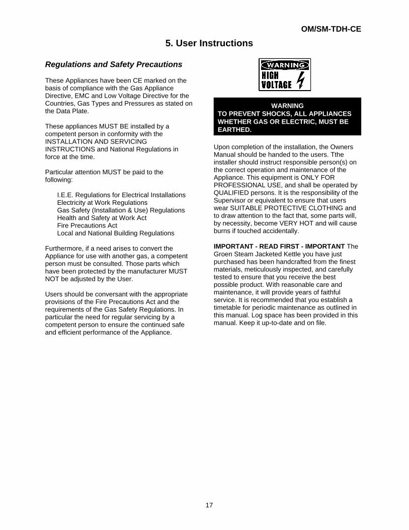
WARNING: TO PREVENT SHOCKS, ALL APPLIANCES GAS OR ELECTRIC, MUST BEEARTHED.
UPON COMPLETION OF THE INSTALLATION, THE OWNERS MANUAL SHOULD BE HANDED TOTHE USERS AND THE INSTALLER SHOULD INSTRUCT THE RESPONSIBLE PERSON(S) IN THECORRECT OPERATION AND MAINTENANCE OF THE APPLIANCE.THIS EQUIPMENT IS ONLY FOR PROFESSIONAL USE, AND SHALL BE OPERATED BY QUALIFIEDPERSONS. IT IS THE RESPONSIBILITY OF THE SUPERVISOR OR EQUIVALENT TO ENSURE THATUSERS WEAR SUITABLE PROTECTIVE CLOTHING AND TO DRAW ATTENTION TO THE FACTTHAT, SOME PARTS WILL, BY NECESSITY, BECOME VERY HOT AND WILL CAUSE BURNS IFTOUCHED ACCIDENTALLY.
WARNING: BEFORE REMOVING ANY PARTITION OR PANEL, ALWAYS TURN OFF THEELECTRIC POWER AND ALLOW THE FAN TO STOP ROTATING. BEFOREWORKING ON ANY ELECTRICAL COMPONENT, DISCONNECT THE POWERSOURCE FROM THE UNIT.
NOTE: IT IS IMPORTANT THAT THE END-USER ROUTINELY EXAMINE THE FLUE OUTLETON A REGULAR BASIS. DEBRIS COVERING THE FLUE OUTLET CAN CAUSE APOTENTIALLY HAZARDOUS CONDITION. REMOVE ANY FOREIGN MATERIALBEFORE USING THIS PIECE OF EQUIPMENT.
WARNINGS AND CAUTIONS PROVIDED IN THIS OPERATOR AND SERVICE MANUAL MUST BECOMPLIED WITH.
OM/SM-TDH-CE
3
TABLE OF CONTENTS
Section Page1 Installation . . . . . . . . . . . . . . . . . . . . . . . . . . . . . . . . . . . . . . . . . . . . . . . . . . . . . . . . . . 5
1.1 Model Numbers, Net Weights & Dimensions . . . . . . . . . . . . . . . . . . . . . . . . . . . . . . . . 51.2 Siting . . . . . . . . . . . . . . . . . . . . . . . . . . . . . . . . . . . . . . . . . . . . . . . . . . . . . . . . . . . . . . . . 51.3 Clearances . . . . . . . . . . . . . . . . . . . . . . . . . . . . . . . . . . . . . . . . . . . . . . . . . . . . . . . . . . . 51.4 Ventilation . . . . . . . . . . . . . . . . . . . . . . . . . . . . . . . . . . . . . . . . . . . . . . . . . . . . . . . . . . . . 51.5 Electrical Supply . . . . . . . . . . . . . . . . . . . . . . . . . . . . . . . . . . . . . . . . . . . . . . . . . . . . . . . 51.6 Gas Supply . . . . . . . . . . . . . . . . . . . . . . . . . . . . . . . . . . . . . . . . . . . . . . . . . . . . . . . . . . . 51.7 Total Gas Rate - Natural & Propane Gas . . . . . . . . . . . . . . . . . . . . . . . . . . . . . . . . . . . . 61.8 Injector Diameters-Natural and Propane Gas . . . . . . . . . . . . . . . . . . . . . . . . . . . . . . . . 61.9 Gas Pressure Adjustment . . . . . . . . . . . . . . . . . . . . . . . . . . . . . . . . . . . . . . . . . . . . . . . 6
2 Assembly and Conditioning . . . . . . . . . . . . . . . . . . . . . . . . . . . . . . . . . . . . . . . . . . . . 72.1 Assembly . . . . . . . . . . . . . . . . . . . . . . . . . . . . . . . . . . . . . . . . . . . . . . . . . . . . . . . . . . . . 72.2 Gas Supply . . . . . . . . . . . . . . . . . . . . . . . . . . . . . . . . . . . . . . . . . . . . . . . . . . . . . . . . . . . 72.3 Electrical Supply . . . . . . . . . . . . . . . . . . . . . . . . . . . . . . . . . . . . . . . . . . . . . . . . . . . . . . . 72.4 Jacket Water Level/Jacket Pressure . . . . . . . . . . . . . . . . . . . . . . . . . . . . . . . . . . . . . . . 72.5 Pre-Commissioning Check . . . . . . . . . . . . . . . . . . . . . . . . . . . . . . . . . . . . . . . . . . . . . . . 72.6 Instruction to User . . . . . . . . . . . . . . . . . . . . . . . . . . . . . . . . . . . . . . . . . . . . . . . . . . . . . 8
3 Servicing and Conversion . . . . . . . . . . . . . . . . . . . . . . . . . . . . . . . . . . . . . . . . . . . . . . 93.1 Conversion . . . . . . . . . . . . . . . . . . . . . . . . . . . . . . . . . . . . . . . . . . . . . . . . . . . . . . . . . . . 93.2 Jacket Vacuum . . . . . . . . . . . . . . . . . . . . . . . . . . . . . . . . . . . . . . . . . . . . . . . . . . . . . . . 103.3 Jacket Filling . . . . . . . . . . . . . . . . . . . . . . . . . . . . . . . . . . . . . . . . . . . . . . . . . . . . . . . . . 103.4 Water Treatment Procedure . . . . . . . . . . . . . . . . . . . . . . . . . . . . . . . . . . . . . . . . . . . . 103.5 Removal of Control Panels . . . . . . . . . . . . . . . . . . . . . . . . . . . . . . . . . . . . . . . . . . . . . . 113.6 Removal of Spark Ignition Module . . . . . . . . . . . . . . . . . . . . . . . . . . . . . . . . . . . . . . . . 113.7 Removal of Low Water Level Control . . . . . . . . . . . . . . . . . . . . . . . . . . . . . . . . . . . . . . 113.8 Removal of Tilt Switch . . . . . . . . . . . . . . . . . . . . . . . . . . . . . . . . . . . . . . . . . . . . . . . . . 113.9 Removal of Gas Control Valve . . . . . . . . . . . . . . . . . . . . . . . . . . . . . . . . . . . . . . . . . . . 123.10 ON/OFF Switch and Reset Button . . . . . . . . . . . . . . . . . . . . . . . . . . . . . . . . . . . . . . . . 123.11 Removal of Neons . . . . . . . . . . . . . . . . . . . . . . . . . . . . . . . . . . . . . . . . . . . . . . . . . . . . 123.12 Removal of Thermostat . . . . . . . . . . . . . . . . . . . . . . . . . . . . . . . . . . . . . . . . . . . . . . . . 123.13 Removal of Pressure Switch . . . . . . . . . . . . . . . . . . . . . . . . . . . . . . . . . . . . . . . . . . . . 133.14 Low Water Level Sensor . . . . . . . . . . . . . . . . . . . . . . . . . . . . . . . . . . . . . . . . . . . . . . . 133.15 Removal of the Burner . . . . . . . . . . . . . . . . . . . . . . . . . . . . . . . . . . . . . . . . . . . . . . . . . 133.16 Removal of Pilot Assembly/Injector . . . . . . . . . . . . . . . . . . . . . . . . . . . . . . . . . . . . . . . 133.17 Spark Electrode/Flame Sensing Bracket . . . . . . . . . . . . . . . . . . . . . . . . . . . . . . . . . . . 143.18 Removal of Pressure Gauge . . . . . . . . . . . . . . . . . . . . . . . . . . . . . . . . . . . . . . . . . . . . 143.19 Removal of Sight Glass . . . . . . . . . . . . . . . . . . . . . . . . . . . . . . . . . . . . . . . . . . . . . . . . 143.20 Safety Valve . . . . . . . . . . . . . . . . . . . . . . . . . . . . . . . . . . . . . . . . . . . . . . . . . . . . . . . . . 143.21 Filling Valve . . . . . . . . . . . . . . . . . . . . . . . . . . . . . . . . . . . . . . . . . . . . . . . . . . . . . . . . . 153.22 Fuse Replacement . . . . . . . . . . . . . . . . . . . . . . . . . . . . . . . . . . . . . . . . . . . . . . . . . . . . 15
4 Troubleshooting . . . . . . . . . . . . . . . . . . . . . . . . . . . . . . . . . . . . . . . . . . . . . . . . . . . . . 155 User Instructions . . . . . . . . . . . . . . . . . . . . . . . . . . . . . . . . . . . . . . . . . . . . . . . . . . . . 17
5.1 Equipment Description . . . . . . . . . . . . . . . . . . . . . . . . . . . . . . . . . . . . . . . . . . . . . . . . . 185.2 Lighting and Operation . . . . . . . . . . . . . . . . . . . . . . . . . . . . . . . . . . . . . . . . . . . . . . . . . 195.3 Cleaning and Maintenance . . . . . . . . . . . . . . . . . . . . . . . . . . . . . . . . . . . . . . . . . . . . . . 21
Parts List . . . . . . . . . . . . . . . . . . . . . . . . . . . . . . . . . . . . . . . . . . . . . . . . . . . . . . . . . . . 23Electrical Schematic . . . . . . . . . . . . . . . . . . . . . . . . . . . . . . . . . . . . . . . . . . . . . . . . . 28Service Log . . . . . . . . . . . . . . . . . . . . . . . . . . . . . . . . . . . . . . . . . . . . . . . . . . . . . . . . . 29Warranty . . . . . . . . . . . . . . . . . . . . . . . . . . . . . . . . . . . . . . . . . . . . . . . . . . . . . . . . . . . 30
OM/SM-TDH-CE
4
Regulations and Safety Precautions
These Appliances have been CE marked on the basis of compliance with the Gas Appliance Directive,EMC and Low Voltage Directive for the Countries, Gas Types and Pressures as stated on the Data Plate.
These appliances MUST BE installed by a competent person in conformity with the INSTALLATION ANDSERVICING INSTRUCTIONS and National Regulations in force at the time.
Particular attention MUST be paid to the following:
I.E.E. Regulations for Electrical InstallationsElectricity at Work RegulationsGas Safety (Installation & Use) RegulationsHealth and Safety at Work ActFire Precautions ActLocal and National Building Regulations
Furthermore, if a need arises to convert the Appliance for use with another gas, a competent person mustbe consulted. Those parts which have been protected by the manufacturer MUST NOT be adjusted by theUser.
Users should be conversant with the appropriate provisions of the Fire Precautions Act and therequirements of the Gas Safety Regulations. In particular the need for regular servicing by a competentperson to ensure the continued safe and efficient performance of the Appliance.
WARNINGTO PREVENT SHOCKS, ALL APPLIANCES WHETHER GAS OR ELECTRIC, MUST BE EARTHED.
Upon completion of the installation, the Owners Manual should be handed to the users and the installershould instruct the responsible person(s) on the correct operation and maintenance of the Appliance. Thisequipment is ONLY FOR PROFESSIONAL USE, and shall be operated by QUALIFIED persons. It is theresponsibility of the Supervisor or equivalent to ensure that users wear SUITABLE PROTECTIVECLOTHING and to draw attention to the fact that, some parts will, by necessity, become VERY HOT andwill cause burns if touched accidentally.
IMPORTANT - READ FIRST - IMPORTANT The Groen Steam Jacketed Kettle you have just purchasedhas been handcrafted from the finest materials, meticulously inspected, and carefully tested to ensure thatyou receive the best possible product. With reasonable care and periodic maintenance, it will provideyears of faithful service. It is recommended that you establish a timetable for periodic maintenance asoutlined in this manual. Space has been provided in the Maintenance & Service Log in the UserInstructions section (Page 23). Keep it up-to-date and on file.
OM/SM-TDH-CE
5
1. Installation
UNLESS OTHERWISE STATED, PARTS WHICH HAVE BEEN PROTECTED BY THE MANUFACTURERARE NOT TO BE ADJUSTED BY THE INSTALLER.
1.1 Model Numbers, Net Weights andDimensions
MODEL, TDH - 20 TDH - 40
WIDTH mm (in) 610 (24.0) 685 (26.9)
DEPTH mm (in) 800 (31.5) 830 (32.6)
HEIGHT mm (in) 645 (25.4) 725 (28.5)
WEIGHT kg (lbs) 98 (215) 110 (240)
1.2 Siting
The appliance should be installed on a level tabletop in a well lit and draught free position. Theinstallation of the appliance must be executed inaccordance with local and/or national regulationsas listed in this manual.
1.3 Clearances
Minimum clearances of 150 mm (5.9 in) from thesides of the appliance and 250 mm (9.8 in) fromthe rear of the appliance are required if theappliance is installed next to combustible surfaces.
A vertical clearance of 750 mm (29.6 in) minimumshould be allowed between the top rim of kettleand any overlying surface.
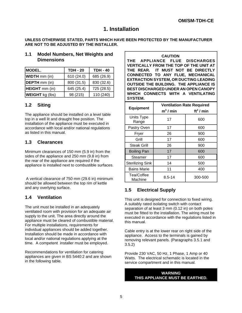
1.4 Ventilation
The unit must be installed in an adequatelyventilated room with provision for an adequate airsupply to the unit. The area directly around theappliance must be cleared of combustible material.For multiple installations, requirements forindividual appliances should be added together. Installation should be made in accordance withlocal and/or national regulations applying at thetime. A competent installer must be employed.
Recommendations for ventilation for cateringappliances are given in BS 5440:2 and are shownin the following table.
CAUTION THE APPLIANCE FLUE DISCHARGESVERTICALLY FROM THE TOP OF THE UNIT ATTHE REAR. IT MUST NOT BE DIRECTLYCONNECTED TO ANY FLUE, MECHANICALEXTRACTION SYSTEM, OR DUCTING LEADINGOUTSIDE THE BUILDING. THE APPLIANCE ISBEST DISCHARGED UNDER AN OPEN CANOPYWHICH CONNECTS WITH A VENTILATINGSYSTEM.
EquipmentVentilation Rate Required
m3 / min ft3 / min
Units TypeRange 17 600
Pastry Oven 17 600Fryer 26 900Grill 17 600
Steak Grill 26 900Boiling Pan 17 600
Steamer 17 600Sterilizing Sink 14 500
Bains Marie 11 400Tea/Coffee
Machine 8.5-14 300-500
1.5 Electrical Supply
This unit is designed for connection to fixed wiring. A suitably rated isolating switch with contactseparation of at least 3 mm (0.12 in) on both polesmust be fitted to the installation. The wiring must beexecuted in accordance with the regulations listed inthis manual.
Cable entry is at the lower rear on right side of theappliance. Access to the terminals is gained byremoving relevant panels. (Paragraphs 3.5.1 and3.5.2)
Provide 230 VAC, 50 Hz, 1 Phase, 1 Amp or 40Watts. The electrical schematic is located in theservice compartment and in this manual.
WARNINGTHIS APPLIANCE MUST BE EARTHED.
OM/SM-TDH-CE
6
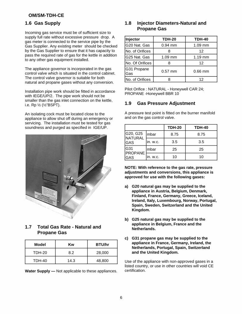
1.6 Gas Supply
Incoming gas service must be of sufficient size tosupply full rate without excessive pressure drop. Agas meter is connected to the service pipe by theGas Supplier. Any existing meter should be checkedby the Gas Supplier to ensure that it has capacity topass the required rate of gas for the kettle in additionto any other gas equipment installed.
The appliance governor is incorporated in the gascontrol valve which is situated in the control cabinet.The control valve governor is suitable for bothnatural and propane gases without any conversion.
Installation pipe work should be fitted in accordancewith IEGE/UP/2. The pipe work should not besmaller than the gas inlet connection on the kettle,i.e. Rp ½ (½”BSPT).
An isolating cock must be located close to theappliance to allow shut off during an emergency orservicing. The installation must be tested for gassoundness and purged as specified in IGE/UP.
1.7 Total Gas Rate - Natural andPropane Gas
Model Kw BTU/hr
TDH-20 8.2 28,000
TDH-40 14.3 48,800
Water Supply — Not applicable to these appliances.
1.8 Injector Diameters-Natural andPropane Gas
Injector TDH-20 TDH-40
G20 Nat. Gas 0.94 mm 1.09 mmNo. of Orifices 8 12G25 Nat. Gas 1.09 mm 1.19 mmNo. Of Orifices 8 12G31 PropaneGas 0.57 mm 0.66 mm
No. of Orifices 8 12
Pilot Orifice : NATURAL - Honeywell CAR 24; PROPANE -Honeywell BBR 10
1.9 Gas Pressure Adjustment
A pressure test point is fitted on the burner manifoldand on the gas control valve.
TDH-20 TDH-40
G20, G25NATURALGAS
mbar 8.75 8.75
in. w.c. 3.5 3.5
G31PROPANEGAS
mbar 25 25
in. w.c. 10 10
NOTE: With reference to the gas rate, pressureadjustments and conversions, this appliance isapproved for use with the following gases:
a) G20 natural gas may be supplied to theappliance in Austria, Belgium, Denmark,Finland, France, Germany, Greece, Iceland,Ireland, Italy, Luxembourg, Norway, Portugal,Spain, Sweden, Switzerland and the UnitedKingdom.
b) G25 natural gas may be supplied to theappliance in Belgium, France and theNetherlands.
c) G31 propane gas may be supplied to theappliance in France, Germany, Ireland, theNetherlands, Portugal, Spain, Switzerlandand the United Kingdom.
Use of the appliance with non-approved gases in alisted country, or use in other countries will void CEcertification.
OM/SM-TDH-CE
7
2. Assembly and Commissioning
2.1 Assembly
a) Unpack the appliance
b) Place on a firm, level table.
2.2 Gas Supply
Connect the unit to the gas supply and test for gassoundness. For that part of the integral gas supplydown stream of the gas valve, leak detection sprayor soap solution may be used with the burners lit.
CAUTIONENSURE THAT THE PAN CONTAINS LIQUIDWHEN THE BURNERS ARE ALIGHT.
2.3 Electrical Supply
Before commissioning the appliance, ensure that theelectrical installation has been carried out accordingto relevant regulations. (Paragraph 1.5.).
WARNINGTHIS APPLIANCE MUST BE EARTHED.
2.4 Jacket Water Level/JacketPressure
a) Ensure that the jacket water level is correct byconfirming that the level is in the middle of thesight glass. If the water is low, follow theinstructions under "Jacket Filling" (Paragraph3.3).
b) Check the pressure gauge. If the gauge does notshow 20 or more inches of vacuum (that is, areading of 20 to 30 below zero) see "JacketVacuum" (Paragraph 3.2).
2.5 Pre-Commissioning Check
a) Prior to operation, clean out kettle panthoroughly using hot water and detergent. Rinsepan thoroughly.
b) Remove all literature and packing materials fromthe interior and exterior of the unit.
c) Ensure the open end or the elbow at the outlet ofthe safety valve is directed down. If it is not, turnthe elbow to the correct position.
2.5.1 Lighting Sequence
Initial Start Up:
a) Put a small amount of water in the kettle pan.
b) Ensure gas and electricity mains are on.
c) Switch the toggle switch to the "on" position.
d) Turn thermostat dial to desired setting.
e) Verify that the spark igniter lights the burners.
f) If the unit does not light, the unit will lock-out.Turn the unit off and wait 1-2 minutes beforeattempting to switch the unit on again.
g) Press reset lock-out switch and repeat steps (b)to (e).
h) To turn the unit off, switch toggle (On/Off) switchto the “Off” position.
i) Turn gas and electricity mains off.
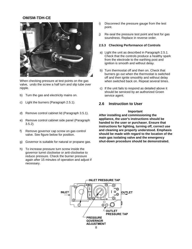
2.5.2 Setting The Gas Pressure
a) It is necessary to check the gas pressure duringcommissioning. A suitable pressure gauge mustbe connected to the pressure test point on thegas control valve or the gas manifold. See belowfor test points on the gas control valve.
OM/SM-TDH-CE
8
When checking pressure at test points on the gasvalve, undo the screw a half turn and slip tube overnipple.
b) Turn the gas and electricity mains on.
c) Light the burners (Paragraph 2.5.1).
d) Remove control cabinet lid (Paragraph 3.5.1).
e) Remove control cabinet side panel (Paragraph3.5.2).
f) Remove governor cap screw on gas controlvalve. See figure below for position.
g) Governor is suitable for natural or propane gas.
h) To increase pressure turn screw inside thegovernor turret clockwise or anti-clockwise toreduce pressure. Check the burner pressureagain after 15 minutes of operation and adjust ifnecessary.
i) Disconnect the pressure gauge from the testpoint.
j) Re-seal the pressure test point and test for gassoundness. Replace in reverse order.
2.5.3 Checking Performance of Controls
a) Light the unit as described in Paragraph 2.5.1. Check that the controls produce a healthy sparkfrom the electrode to the earthing post andignition is smooth and without delay.
b) Turn thermostat off and then on. Check thatburners go out when the thermostat is switchedoff and then ignite smoothly and without delaywhen switched back on. Repeat several times.
c) If the unit fails to respond as detailed above itshould be serviced by an authorized Groenservice agent.
2.6 Instruction to User
Important After installing and commissioning theappliance, the user's instructions should behanded to the user or purchaser. Ensure thatinstructions for lighting, turning off, correct useand cleaning are properly understood. Emphasisshould be made with regard to the location of themain gas isolating valve and the emergencyshut-down procedure should be demonstrated.
OM/SM-TDH-CE
9
3. Servicing and Conversion
Important
Before attempting any servicing, ensure that thegas isolating cock is turned off and cannot beinadvertently turned on. Disconnect theelectricity supply.
After any maintenance task, check the applianceto ensure that it performs correctly. Carry outnecessary adjustments as detailed in Section 1. After any servicing or exchange of gas carryingcomponents:
ALWAYS CHECK FOR GAS SOUNDNESS
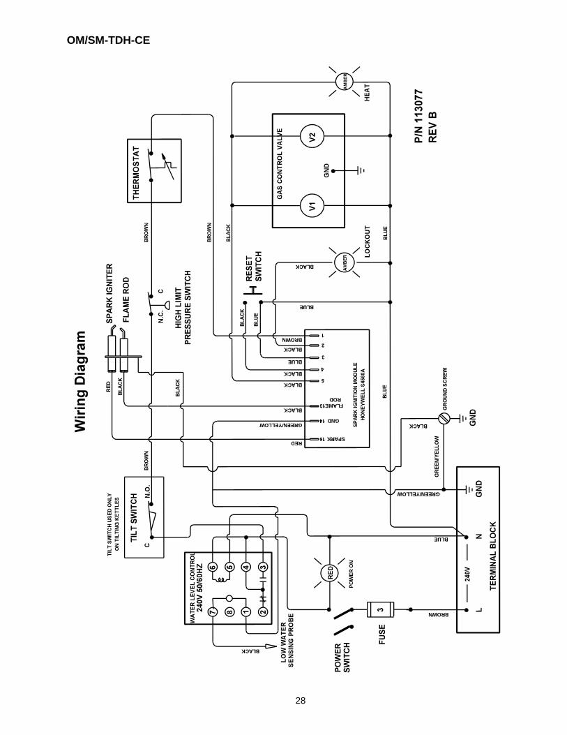
NOTE: When replacing wiring connections refer tothe wiring diagram contained on the unit and in thismanual.
After Servicing
a) Test for gas soundness as specified in IGE/UP1as appropriate after any gas connection hasbeen disturbed.
b) Check for correct operation, as appropriate (seecommissioning of appliance).
Regular Servicing Procedures
The following must be serviced at regular intervals.
Burners
The burner should be cleaned periodically tomaintain maximum performance. Burners are bestcleaned with a wire brush. Any blocked parts arebest cleaned with a metal broach, taking care not todamage the burner head. The injector orifice should be cleaned with a woodensplinter. Metal reamers could distort or increase theorifice size and should be avoided.
Gears
The gear housing has fittings for lubrication ofmoving parts. Because the gears do not run in oil,periodic lubrication with grease is necessary.Lubrication frequency depends on operatingconditions, but should be performed at least onceevery six months. A #2 grade LGI lithium grease isrecommended. Add grease through the Zerk fittings
on the gear housing until grease flows out of thebearings around the shaft. Put a liberal amount ofgrease on the gear to cover the arc of contact withthe gear.
Safety Valve
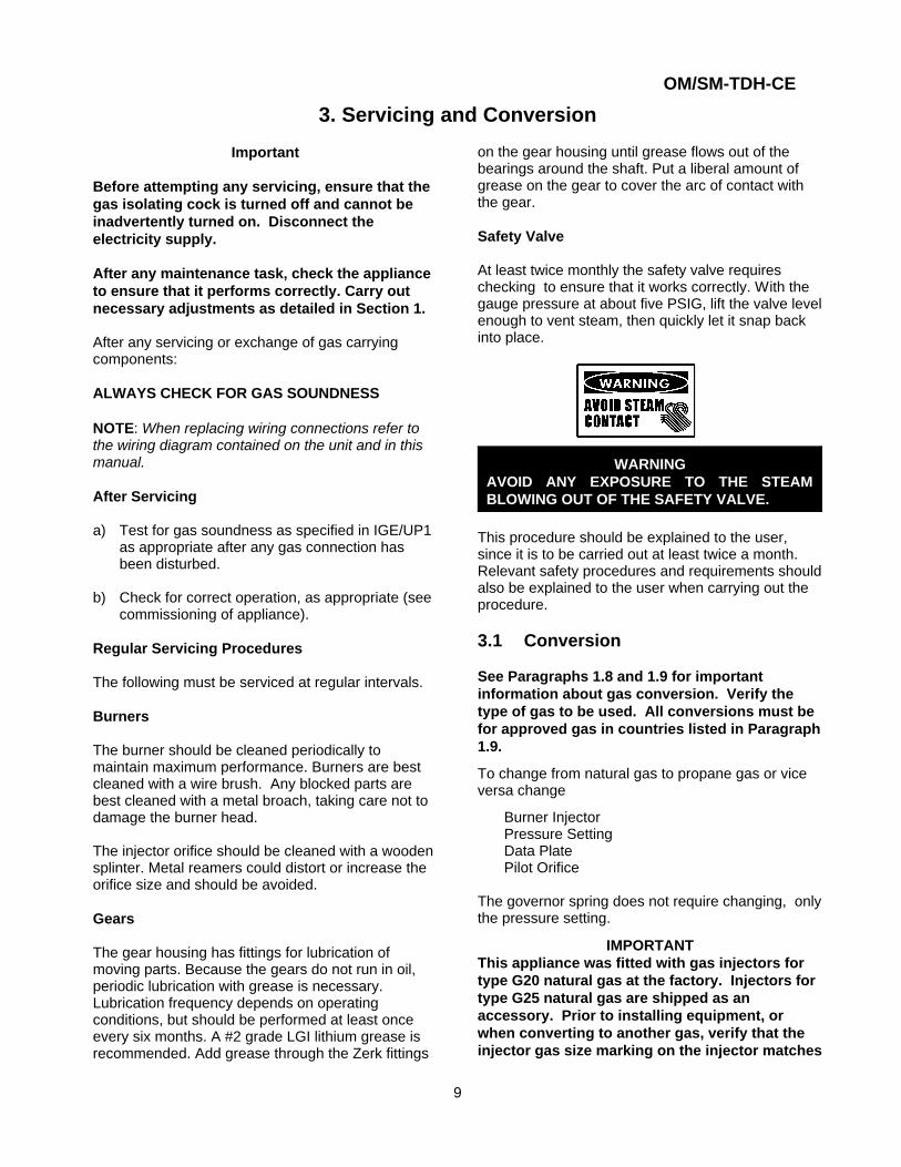
At least twice monthly the safety valve requireschecking to ensure that it works correctly. With thegauge pressure at about five PSIG, lift the valve levelenough to vent steam, then quickly let it snap backinto place.
WARNINGAVOID ANY EXPOSURE TO THE STEAMBLOWING OUT OF THE SAFETY VALVE.
This procedure should be explained to the user,since it is to be carried out at least twice a month.Relevant safety procedures and requirements shouldalso be explained to the user when carrying out theprocedure.
3.1 Conversion
See Paragraphs 1.8 and 1.9 for importantinformation about gas conversion. Verify thetype of gas to be used. All conversions must befor approved gas in countries listed in Paragraph1.9.
To change from natural gas to propane gas or viceversa change
Burner InjectorPressure SettingData PlatePilot Orifice
The governor spring does not require changing, onlythe pressure setting.
IMPORTANTThis appliance was fitted with gas injectors fortype G20 natural gas at the factory. Injectors fortype G25 natural gas are shipped as anaccessory. Prior to installing equipment, orwhen converting to another gas, verify that theinjector gas size marking on the injector matches
OM/SM-TDH-CE
10
information on the data plate for the type of gasbeing used.
3.2 Jacket Vacuum
When the kettle is cold, a positive reading or areading near zero on the pressure vacuum gaugeindicates excess air in the jacket. Air in the jacketslows down kettle heating. To remove air:
a) Light the unit (Paragraph 2.5.1).
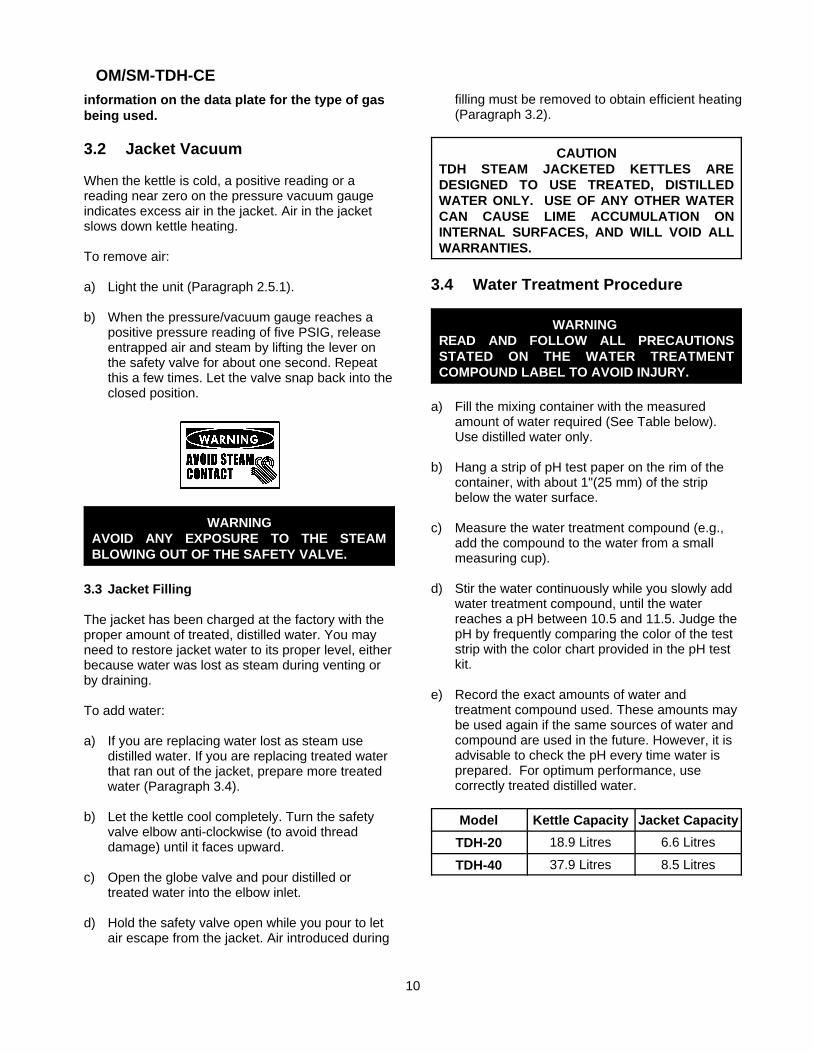
b) When the pressure/vacuum gauge reaches apositive pressure reading of five PSIG, releaseentrapped air and steam by lifting the lever onthe safety valve for about one second. Repeatthis a few times. Let the valve snap back into theclosed position.
WARNINGAVOID ANY EXPOSURE TO THE STEAMBLOWING OUT OF THE SAFETY VALVE.
3.3 Jacket Filling
The jacket has been charged at the factory with theproper amount of treated, distilled water. You mayneed to restore jacket water to its proper level, eitherbecause water was lost as steam during venting orby draining.
To add water:
a) If you are replacing water lost as steam usedistilled water. If you are replacing treated waterthat ran out of the jacket, prepare more treatedwater (Paragraph 3.4).
b) Let the kettle cool completely. Turn the safetyvalve elbow anti-clockwise (to avoid threaddamage) until it faces upward.
c) Open the globe valve and pour distilled ortreated water into the elbow inlet.
d) Hold the safety valve open while you pour to letair escape from the jacket. Air introduced during
filling must be removed to obtain efficient heating(Paragraph 3.2).
CAUTIONTDH STEAM JACKETED KETTLES AREDESIGNED TO USE TREATED, DISTILLEDWATER ONLY. USE OF ANY OTHER WATERCAN CAUSE LIME ACCUMULATION ONINTERNAL SURFACES, AND WILL VOID ALLWARRANTIES.
3.4 Water Treatment Procedure
WARNING READ AND FOLLOW ALL PRECAUTIONSSTATED ON THE WATER TREATMENTCOMPOUND LABEL TO AVOID INJURY.
a) Fill the mixing container with the measuredamount of water required (See Table below).Use distilled water only.
b) Hang a strip of pH test paper on the rim of thecontainer, with about 1"(25 mm) of the stripbelow the water surface.
c) Measure the water treatment compound (e.g.,add the compound to the water from a smallmeasuring cup).
d) Stir the water continuously while you slowly addwater treatment compound, until the waterreaches a pH between 10.5 and 11.5. Judge thepH by frequently comparing the color of the teststrip with the color chart provided in the pH testkit.
e) Record the exact amounts of water andtreatment compound used. These amounts maybe used again if the same sources of water andcompound are used in the future. However, it isadvisable to check the pH every time water isprepared. For optimum performance, usecorrectly treated distilled water.
Model Kettle Capacity Jacket Capacity
TDH-20 18.9 Litres 6.6 Litres
TDH-40 37.9 Litres 8.5 Litres
OM/SM-TDH-CE
11
3.5 Remove Control Panels
3.5.1 Remove Control Cabinet Lid (Turn gasand electric mains off)
a) Remove the 2 screws around the edge of the lidsecuring it to the control cabinet.
b) Remove the lid.
c) Replace in reverse order.
3.5.2 Remove Control Cabinet Side Panel (Turngas and electric mains off)
a) Remove lid (Paragraph 3.5.1).
b) Remove the four screws securing the side panelto the control cabinet.
c) Remove panel.
d) Replace in reverse order.
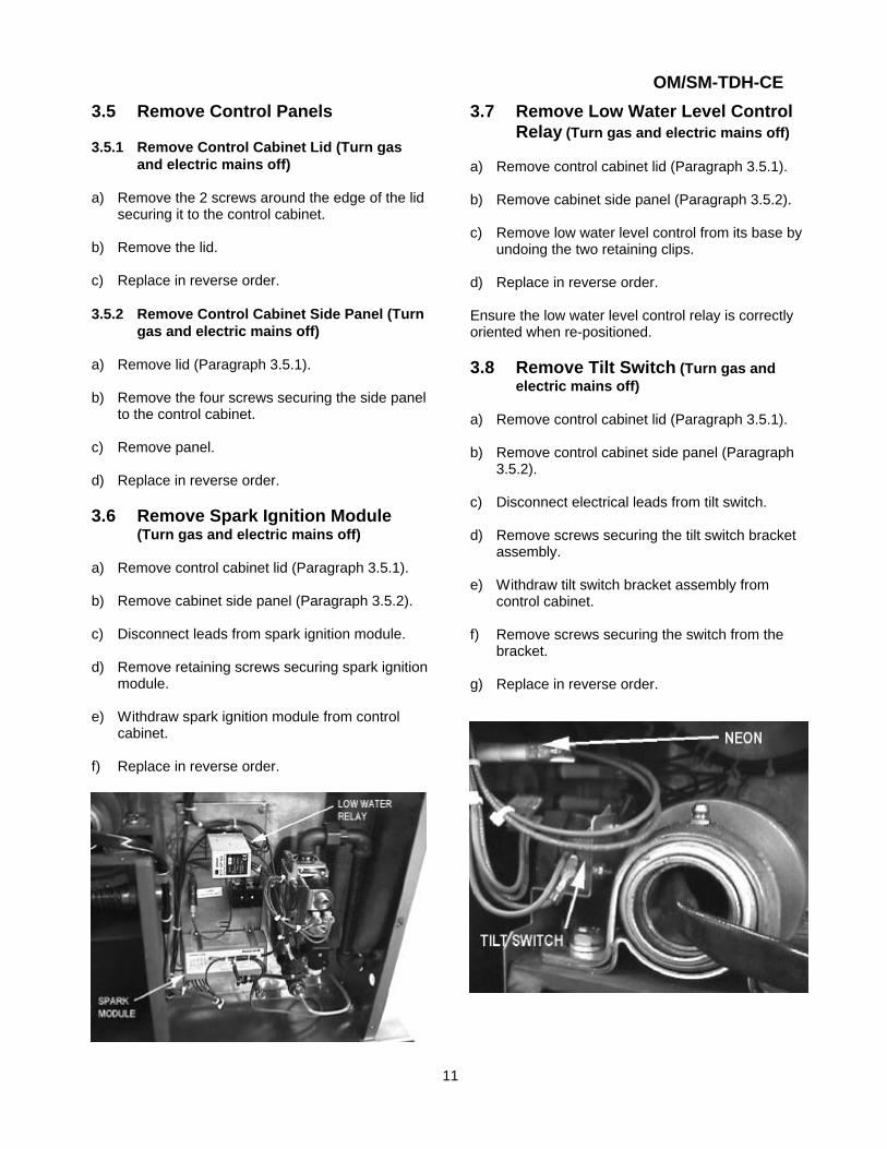
3.6 Remove Spark Ignition Module (Turn gas and electric mains off)
a) Remove control cabinet lid (Paragraph 3.5.1).
b) Remove cabinet side panel (Paragraph 3.5.2).
c) Disconnect leads from spark ignition module.
d) Remove retaining screws securing spark ignitionmodule.
e) Withdraw spark ignition module from controlcabinet.
f) Replace in reverse order.
3.7 Remove Low Water Level ControlRelay (Turn gas and electric mains off)
a) Remove control cabinet lid (Paragraph 3.5.1).
b) Remove cabinet side panel (Paragraph 3.5.2).
c) Remove low water level control from its base byundoing the two retaining clips.
d) Replace in reverse order.
Ensure the low water level control relay is correctlyoriented when re-positioned.
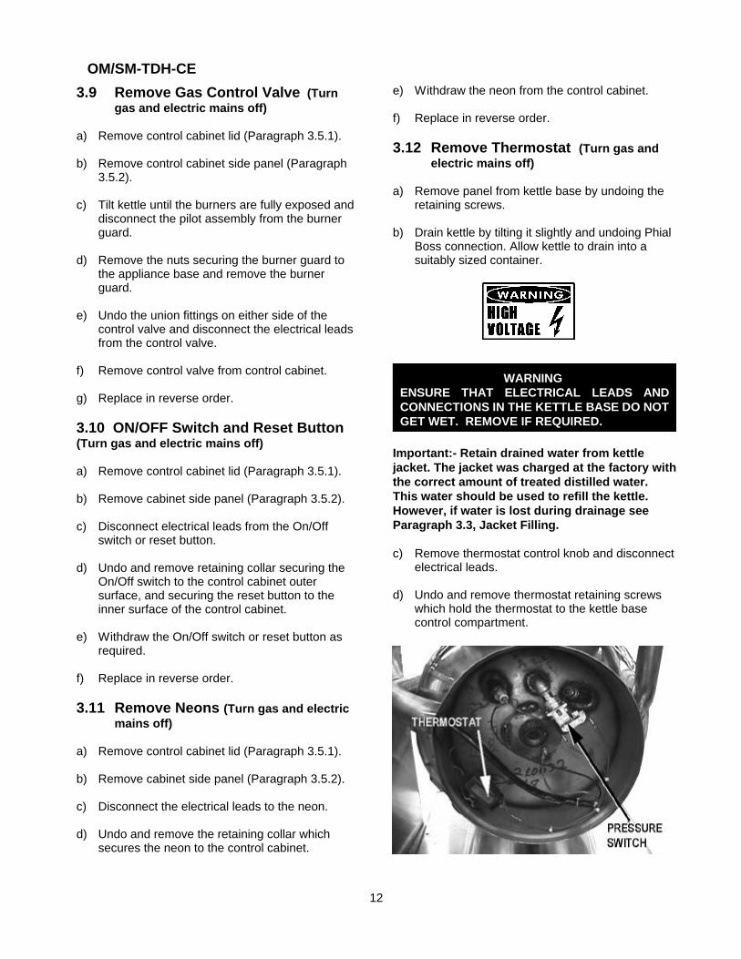
3.8 Remove Tilt Switch (Turn gas andelectric mains off)
a) Remove control cabinet lid (Paragraph 3.5.1).
b) Remove control cabinet side panel (Paragraph 3.5.2).
c) Disconnect electrical leads from tilt switch.
d) Remove screws securing the tilt switch bracketassembly.
e) Withdraw tilt switch bracket assembly fromcontrol cabinet.
f) Remove screws securing the switch from thebracket.
g) Replace in reverse order.
OM/SM-TDH-CE
12
3.9 Remove Gas Control Valve (Turngas and electric mains off)
a) Remove control cabinet lid (Paragraph 3.5.1).
b) Remove control cabinet side panel (Paragraph3.5.2).
c) Tilt kettle until the burners are fully exposed anddisconnect the pilot assembly from the burnerguard.
d) Remove the nuts securing the burner guard tothe appliance base and remove the burnerguard.
e) Undo the union fittings on either side of thecontrol valve and disconnect the electrical leadsfrom the control valve.
f) Remove control valve from control cabinet.
g) Replace in reverse order.
3.10 ON/OFF Switch and Reset Button(Turn gas and electric mains off)
a) Remove control cabinet lid (Paragraph 3.5.1).
b) Remove cabinet side panel (Paragraph 3.5.2).
c) Disconnect electrical leads from the On/Offswitch or reset button.
d) Undo and remove retaining collar securing theOn/Off switch to the control cabinet outersurface, and securing the reset button to theinner surface of the control cabinet.
e) Withdraw the On/Off switch or reset button asrequired.
f) Replace in reverse order.
3.11 Remove Neons (Turn gas and electricmains off)
a) Remove control cabinet lid (Paragraph 3.5.1).
b) Remove cabinet side panel (Paragraph 3.5.2).
c) Disconnect the electrical leads to the neon.
d) Undo and remove the retaining collar whichsecures the neon to the control cabinet.
e) Withdraw the neon from the control cabinet.
f) Replace in reverse order.
3.12 Remove Thermostat (Turn gas andelectric mains off)
a) Remove panel from kettle base by undoing theretaining screws.
b) Drain kettle by tilting it slightly and undoing PhialBoss connection. Allow kettle to drain into asuitably sized container.
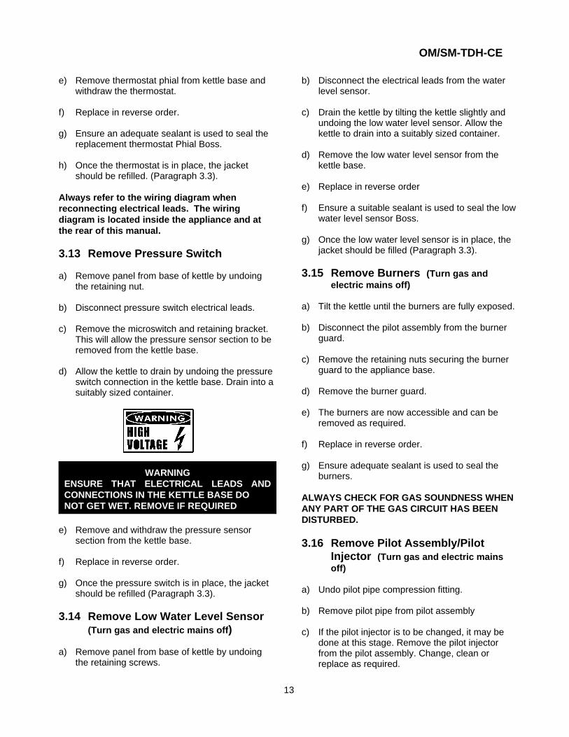
WARNING ENSURE THAT ELECTRICAL LEADS ANDCONNECTIONS IN THE KETTLE BASE DO NOTGET WET. REMOVE IF REQUIRED.
Important:- Retain drained water from kettlejacket. The jacket was charged at the factory withthe correct amount of treated distilled water.This water should be used to refill the kettle.However, if water is lost during drainage seeParagraph 3.3, Jacket Filling. c) Remove thermostat control knob and disconnect
electrical leads.
d) Undo and remove thermostat retaining screwswhich hold the thermostat to the kettle basecontrol compartment.
OM/SM-TDH-CE
13
e) Remove thermostat phial from kettle base andwithdraw the thermostat.
f) Replace in reverse order.
g) Ensure an adequate sealant is used to seal thereplacement thermostat Phial Boss.
h) Once the thermostat is in place, the jacketshould be refilled. (Paragraph 3.3).
Always refer to the wiring diagram whenreconnecting electrical leads. The wiringdiagram is located inside the appliance and atthe rear of this manual.
3.13 Remove Pressure Switch
a) Remove panel from base of kettle by undoingthe retaining nut.
b) Disconnect pressure switch electrical leads.
c) Remove the microswitch and retaining bracket.This will allow the pressure sensor section to beremoved from the kettle base.
d) Allow the kettle to drain by undoing the pressureswitch connection in the kettle base. Drain into asuitably sized container.
WARNINGENSURE THAT ELECTRICAL LEADS ANDCONNECTIONS IN THE KETTLE BASE DO NOT GET WET. REMOVE IF REQUIRED
e) Remove and withdraw the pressure sensorsection from the kettle base.
f) Replace in reverse order.
g) Once the pressure switch is in place, the jacketshould be refilled (Paragraph 3.3).
3.14 Remove Low Water Level Sensor (Turn gas and electric mains off)
a) Remove panel from base of kettle by undoingthe retaining screws.
b) Disconnect the electrical leads from the waterlevel sensor.
c) Drain the kettle by tilting the kettle slightly andundoing the low water level sensor. Allow thekettle to drain into a suitably sized container.
d) Remove the low water level sensor from thekettle base.
e) Replace in reverse order
f) Ensure a suitable sealant is used to seal the lowwater level sensor Boss.
g) Once the low water level sensor is in place, thejacket should be filled (Paragraph 3.3).
3.15 Remove Burners (Turn gas andelectric mains off)
a) Tilt the kettle until the burners are fully exposed.
b) Disconnect the pilot assembly from the burnerguard.
c) Remove the retaining nuts securing the burnerguard to the appliance base.
d) Remove the burner guard.
e) The burners are now accessible and can beremoved as required.
f) Replace in reverse order.
g) Ensure adequate sealant is used to seal theburners.
ALWAYS CHECK FOR GAS SOUNDNESS WHENANY PART OF THE GAS CIRCUIT HAS BEENDISTURBED.
3.16 Remove Pilot Assembly/PilotInjector (Turn gas and electric mainsoff)
a) Undo pilot pipe compression fitting.
b) Remove pilot pipe from pilot assembly
c) If the pilot injector is to be changed, it may bedone at this stage. Remove the pilot injectorfrom the pilot assembly. Change, clean orreplace as required.
OM/SM-TDH-CE
14
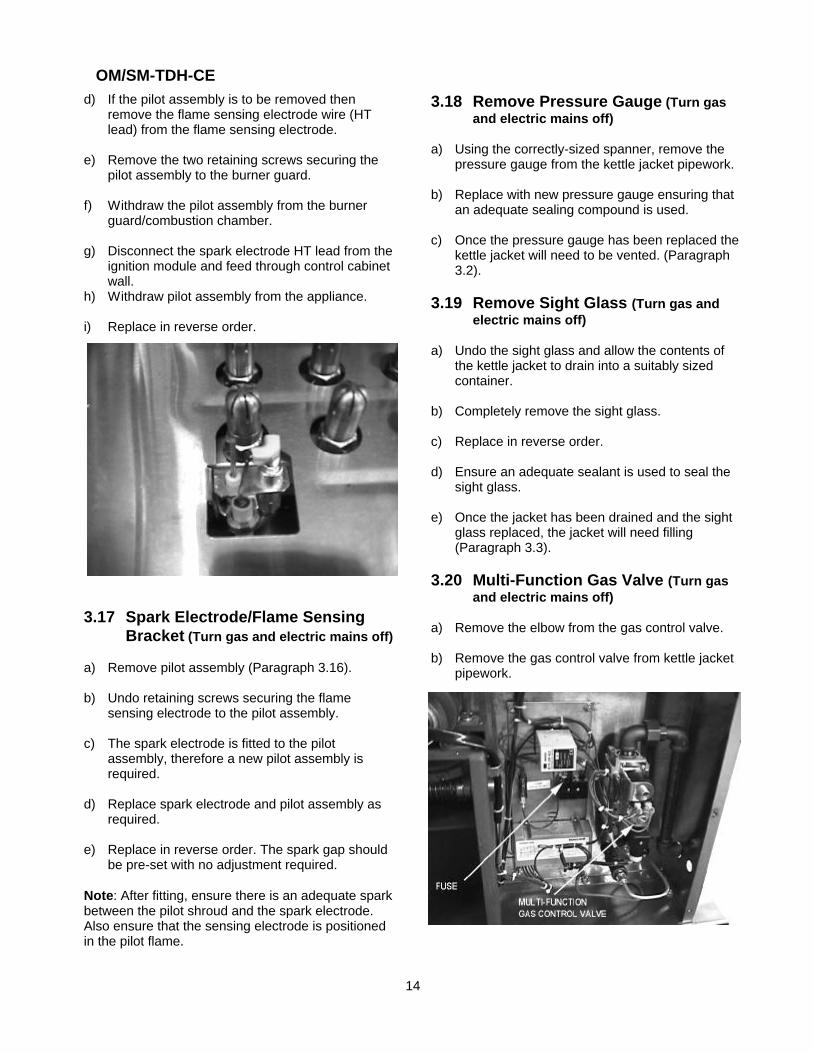
d) If the pilot assembly is to be removed thenremove the flame sensing electrode wire (HTlead) from the flame sensing electrode.
e) Remove the two retaining screws securing thepilot assembly to the burner guard.
f) Withdraw the pilot assembly from the burnerguard/combustion chamber.
g) Disconnect the spark electrode HT lead from theignition module and feed through control cabinetwall.
h) Withdraw pilot assembly from the appliance.
i) Replace in reverse order.
3.17 Spark Electrode/Flame SensingBracket (Turn gas and electric mains off)
a) Remove pilot assembly (Paragraph 3.16).
b) Undo retaining screws securing the flamesensing electrode to the pilot assembly.
c) The spark electrode is fitted to the pilotassembly, therefore a new pilot assembly isrequired.
d) Replace spark electrode and pilot assembly asrequired.
e) Replace in reverse order. The spark gap shouldbe pre-set with no adjustment required.
Note: After fitting, ensure there is an adequate sparkbetween the pilot shroud and the spark electrode. Also ensure that the sensing electrode is positionedin the pilot flame.
3.18 Remove Pressure Gauge (Turn gasand electric mains off)
a) Using the correctly-sized spanner, remove thepressure gauge from the kettle jacket pipework.
b) Replace with new pressure gauge ensuring thatan adequate sealing compound is used.
c) Once the pressure gauge has been replaced thekettle jacket will need to be vented. (Paragraph3.2).
3.19 Remove Sight Glass (Turn gas andelectric mains off)
a) Undo the sight glass and allow the contents ofthe kettle jacket to drain into a suitably sizedcontainer.
b) Completely remove the sight glass.
c) Replace in reverse order.
d) Ensure an adequate sealant is used to seal thesight glass.
e) Once the jacket has been drained and the sightglass replaced, the jacket will need filling(Paragraph 3.3).
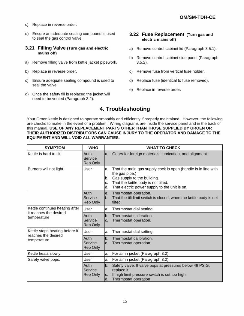
3.20 Multi-Function Gas Valve (Turn gasand electric mains off)
a) Remove the elbow from the gas control valve.
b) Remove the gas control valve from kettle jacketpipework.
OM/SM-TDH-CE
15
c) Replace in reverse order.
d) Ensure an adequate sealing compound is usedto seal the gas control valve.
3.21 Filling Valve (Turn gas and electricmains off)
a) Remove filling valve from kettle jacket pipework.
b) Replace in reverse order.
c) Ensure adequate sealing compound is used toseal the valve.
d) Once the safety fill is replaced the jacket willneed to be vented (Paragraph 3.2).
3.22 Fuse Replacement (Turn gas andelectric mains off)
a) Remove control cabinet lid (Paragraph 3.5.1).
b) Remove control cabinet side panel (Paragraph3.5.2).
c) Remove fuse from vertical fuse holder.
d) Replace fuse (identical to fuse removed).
e) Replace in reverse order.
4. Troubleshooting
Your Groen kettle is designed to operate smoothly and efficiently if properly maintained. However, the followingare checks to make in the event of a problem. Wiring diagrams are inside the service panel and in the back ofthis manual. USE OF ANY REPLACEMENT PARTS OTHER THAN THOSE SUPPLIED BY GROEN ORTHEIR AUTHORIZED DISTRIBUTORS CAN CAUSE INJURY TO THE OPERATOR AND DAMAGE TO THEEQUIPMENT AND WILL VOID ALL WARRANTIES.
SYMPTOM WHO WHAT TO CHECK
Kettle is hard to tilt. AuthServiceRep Only
a. Gears for foreign materials, lubrication, and alignment
Burners will not light. User a. That the main gas supply cock is open (handle is in line withthe gas pipe.)
b. Gas supply to the building.c. That the kettle body is not tilted.d. That electric power supply to the unit is on.
AuthServiceRep Only
e. Thermostat operation.f. That the tilt limit switch is closed, when the kettle body is not
tilted.Kettle continues heating afterit reaches the desiredtemperature
User a. Thermostat dial setting.
AuthServiceRep Only
b. Thermostat calibration.c. Thermostat operation.
Kettle stops heating before itreaches the desiredtemperature.
User a. Thermostat dial setting.
AuthServiceRep Only
b. Thermostat calibration.c. Thermostat operation.
Kettle heats slowly. User a. For air in jacket (Paragraph 3.2).Safety valve pops. User a. For air in jacket (Paragraph 3.2).
AuthServiceRep Only
b. Safety valve. If valve pops at pressures below 49 PSIG,replace it.
c. If high limit pressure switch is set too high.d. Thermostat operation
OM/SM-TDH-CE
SYMPTOM WHO WHAT TO CHECK
16
System does not produce aspark.
AuthServiceRep Only
a. Thermostat, and close the contacts, if they are open.b. AC voltage between terminals “1" and GND. If it is not 230
VAC, check the high limit switch, which should be closedc. Pilot spark gap. Regap, if it is not 7/64 inch (2.78 mm).d. Electrode ceramic for crack or break.e. That the high tension cable is firmly attached and in good
condition. If it is cracked or brittle, replace the pilot.f. Replace the electronic spark ignition module.
Spark is present, but the pilotwill not light.
AuthServiceRep Only
a. That the gas valve is opening.b. That gas pressure meets the control manufacturer’s
specifications.c. For gas at the pilot. If it is not flowing:
(1) Check the pilot gas line for kinks and obstructions.(2) Replace the gas control valve.
d. That the pilot spark gap is 7/64 inch (2.78 mm) and located inthe pilot gas stream. If not, adjust or replace the pilot.
e. Orifice, and clean, if necessaryPilot lights, but main burnerwill not come on, and thespark stays on.
AuthServiceRep Only
a. Sensor cable, to make sure of secure attachment to terminal“1" on module and to the sensor.
b. Sensor ceramic for cracks.c. That the cable is not grounded out. If it is, correct the ground.d. Sensor cable for continuity and condition of insulation.e. (1) Check the gas pressure.
(2) Clean the pilot assembly.(3) Tighten mechanical and electrical connections.
Pilot lights, but main burnerwill not come on, and sparkdoes not stay on.
AuthServiceRep Only
a. That gas pressure meets the control manufacturer’sspecifications.
b. Replace spark ignition module.Main burner comes on but willnot stay lit.
AuthServiceRep Only
a. Check burner ground for bad wire or connection. Replace withhigh temperature wire if necessary.
b. Check for low gas supply pressure. If necessary, replaceignition control module.
c. Ceramic insulator or pilot flame sensor cracked. Replaceflame sensor.
OM/SM-TDH-CE
17
5. User Instructions
Regulations and Safety Precautions
These Appliances have been CE marked on thebasis of compliance with the Gas ApplianceDirective, EMC and Low Voltage Directive for theCountries, Gas Types and Pressures as stated onthe Data Plate.
These appliances MUST BE installed by acompetent person in conformity with theINSTALLATION AND SERVICINGINSTRUCTIONS and National Regulations inforce at the time.
Particular attention MUST be paid to thefollowing:
I.E.E. Regulations for Electrical InstallationsElectricity at Work RegulationsGas Safety (Installation & Use) RegulationsHealth and Safety at Work ActFire Precautions ActLocal and National Building Regulations
Furthermore, if a need arises to convert theAppliance for use with another gas, a competentperson must be consulted. Those parts whichhave been protected by the manufacturer MUSTNOT be adjusted by the User.
Users should be conversant with the appropriateprovisions of the Fire Precautions Act and therequirements of the Gas Safety Regulations. Inparticular the need for regular servicing by acompetent person to ensure the continued safeand efficient performance of the Appliance.
WARNINGTO PREVENT SHOCKS, ALL APPLIANCESWHETHER GAS OR ELECTRIC, MUST BEEARTHED.
Upon completion of the installation, the OwnersManual should be handed to the users. Ttheinstaller should instruct responsible person(s) onthe correct operation and maintenance of theAppliance. This equipment is ONLY FORPROFESSIONAL USE, and shall be operated byQUALIFIED persons. It is the responsibility of theSupervisor or equivalent to ensure that userswear SUITABLE PROTECTIVE CLOTHING andto draw attention to the fact that, some parts will,by necessity, become VERY HOT and will causeburns if touched accidentally.
IMPORTANT - READ FIRST - IMPORTANT TheGroen Steam Jacketed Kettle you have justpurchased has been handcrafted from the finestmaterials, meticulously inspected, and carefullytested to ensure that you receive the bestpossible product. With reasonable care andmaintenance, it will provide years of faithfulservice. It is recommended that you establish atimetable for periodic maintenance as outlined inthis manual. Log space has been provided in thismanual. Keep it up-to-date and on file.
OM/SM-TDH-CE
18
5.1 Equipment Description
5.1.1 General
Groen model TDH are stainless steel, steamjacketed, table-top mounted, tilting kettles with aself-contained, gas-heated steam source. The kettlebody is welded into one piece and furnished with areinforced bar rim and welded "butterfly" pouring lip.The interior of the kettle is polished to a 180 emerygrit finish, and the exterior is given a brightsemi-deluxe finish. The unit is ASME shop inspectedand registered with the National Board for workingpressures up to 50 PSIG. Kettle support, tiltingmechanism, and controls are contained in anenclosed compartment resting on a base plate.Tilting is provided by a self-locking, worm-and-geardevice, or a pull tilt handle.
The self-contained steam source is heated bypropane or natural gas and ignition is by electronicspark.
Charged at the factory with treated, distilled water,the steam source provides kettle temperature of65oC to 150oC. Controls include a thermostat,pressure gauge, gauge glass, safety valve, pressurelimit control, low water cut-off, on/off switch and amulti-functional gas control valve.
The gas supply shuts off automatically when thekettle is tilted.
Service connections are required for gas and 230-V,single phase, 50 Hz electricity.
Important:
Prior to operation, clean out the kettle panthoroughly using hot water and detergent. Rinseout and dry thoroughly.
The gas burners are protected by an electronicflame failure device which incorporatesautomatic ignition of the burners and instantshut-off of the gas supply to the burners shoulda gas supply interruption occur.
5.1.2 Available Options
Options available with listed models include:
a) One piece, lift-off cover.
b) Basket inserts.
c) Stand that supports the unit and holds a pan inposition for filling.
d) Fill faucet with swing spout.
e) Kettle Brush Kit.
5.1.3 Operational and Maintenance Safety
WARNINGINSTALLATION OF THE UNIT MUST BE DONEBY PERSONNEL QUALIFIED TO WORK WITHE L E C T R I C I T Y A N D P L U M B I N G I NACCORDANCE WITH ALL APPLICABLE CODES.
BEFORE REPLACING ANY PARTS,DISCONNECT THE UNIT FROM THE ELECTRICPOWER SUPPLY AND CLOSE THE MAIN GASCOCK. ALLOW FIVE MINUTES FOR UNBURNEDGAS TO VENT.
TO PREVENT SHOCKS, ALL APPLIANCESWHETHER GAS OR ELECTRIC, MUST BEEARTHED.
CAUTIONOPERATORS MUST READ, UNDERSTAND ANDFOLLOW CAUTIONS AND SAFETY ANDOPERATING INSTRUCTIONS CONTAINED INTHIS MANUAL.
OM/SM-TDH-CE
19
5.2 Lighting and Operation
5.2.1 Initial Kettle Lighting and OperationalReadiness Check
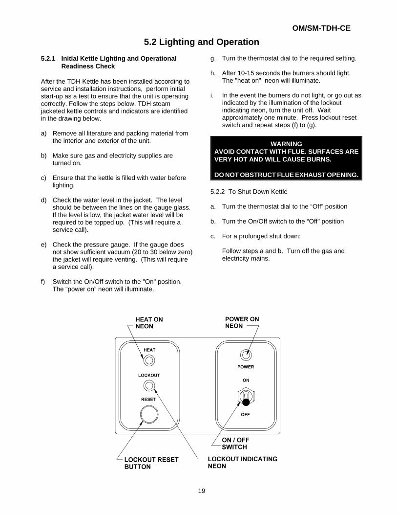
After the TDH Kettle has been installed according toservice and installation instructions, perform initialstart-up as a test to ensure that the unit is operatingcorrectly. Follow the steps below. TDH steamjacketed kettle controls and indicators are identifiedin the drawing below.
a) Remove all literature and packing material fromthe interior and exterior of the unit.
b) Make sure gas and electricity supplies areturned on.
c) Ensure that the kettle is filled with water beforelighting.
d) Check the water level in the jacket. The levelshould be between the lines on the gauge glass. If the level is low, the jacket water level will berequired to be topped up. (This will require aservice call).
e) Check the pressure gauge. If the gauge doesnot show sufficient vacuum (20 to 30 below zero)the jacket will require venting. (This will requirea service call).
f) Switch the On/Off switch to the "On" position.The “power on” neon will illuminate.
g. Turn the thermostat dial to the required setting.
h. After 10-15 seconds the burners should light.The "heat on" neon will illuminate.
i. In the event the burners do not light, or go out as indicated by the illumination of the lockoutindicating neon, turn the unit off. Waitapproximately one minute. Press lockout resetswitch and repeat steps (f) to (g).
WARNINGAVOID CONTACT WITH FLUE. SURFACES AREVERY HOT AND WILL CAUSE BURNS.
DO NOT OBSTRUCT FLUE EXHAUST OPENING.
5.2.2 To Shut Down Kettle
a. Turn the thermostat dial to the “Off” position
b. Turn the On/Off switch to the “Off” position
c. For a prolonged shut down:
Follow steps a and b. Turn off the gas andelectricity mains.
OM/SM-TDH-CE
20
5.2.3 Filling the Kettle
Prior to operating the unit, clean out the kettle panthoroughly, using hot water and detergent.
Kettle capacities:
Model Kettle Capacity
TDH-20 18.9 Litres
TDH-40 37.9 LitresThese are maximum capacities. To prevent surgeboiling, no more than 80% of the maximum capacityshould be used during operation.
5.2.4 User’s Thermostat
Provides automatic control of the Kettle Jackettemperature at selected settings to a maximum of147oC.
5.2.5 Sequence of Operation
The following "sequence of operation" outline isprovided to help the user understand how the unitfunctions.
When the operator sets a temperature on thethermostat dial, the thermostat switch closes andsends a signal which (1) starts the spark and (2)opens the automatic valve for the burners.
The spark ignites the burner on low flow. The flamecompletes a circuit at the sensing probe and sendsa signal that causes the spark to shut off and theautomatic valve to open to full flow once a flamehas been detected. If a flame is not detected within15 seconds the gas is automatically cut-off and theappliance is locked-out. The unit can only be re-litonce the reset button has been pressed.
In addition to the lockout timer, safety featuresinclude:
a) Low-water cut-off relay that will shut off the gassupply to all burners until the water level iscorrected.
b) High pressure switch, set to open at about 46PSIG and shut down the burners until jacketpressure is decreased.
c) Pop safety valve, which will release steam if thejacket pressure exceeds 50 PSIG. See detailedInstructions pertaining to Safety Valveinstallation and operation. (Paragraphs 3.2 and3.20)
d) Tilt cut-off switch that shuts off all burners whenthe kettle is tilted.
When the kettle reaches the set temperature, thethermostat switch opens, stopping the signal to thegas control valve and causing the valve to shut offall gas flow. When the kettle cools below the settemperature, the thermostat switch closes andstarts another heating cycle. On-off cyclingcontinues and maintains the kettle at the desiredtemperature.
5.2.6 To Empty Kettle
5.2.6.1 Crank Tilt Models: To tilt the body of thekettle forward, turn the hand crank on thefront of the cabinet anti-clockwise. Thebody will stay in the position when you stopturning the handle. To return the body tothe upright position, turn the crankclockwise.
5.2.6.2 Pull Tilt Models: The kettle is designed tobe tilted in a controlled manner. Grasp theinsulated plastic ball firmly. Maintain a firmgrip on the handle when tilting, whilekeeping the kettle body in a tilted position,and when slowly returning the kettle bodyto an upright position.
WARNINGDO NOT STAND IN FRONT OF THE KETTLEBODY WHEN TILTING IT. BE CAREFUL TOKEEP HOT CONTENTS FROM SPILLING.ENSURE PEOPLE ARE KEPT AWAY FROM THEKETTLE WHEN EMPTYING IT.
5.2.7 Power Failure
If the power to the unit fails, do not attempt tooperate the appliance until the electricity supply is re-established.
When the power comes back on, follow the steps inInitial Kettle Lighting and Operational ReadinessCheck (Paragraph 5.2.1).
OM/SM-TDH-CE
21
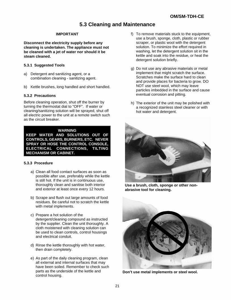
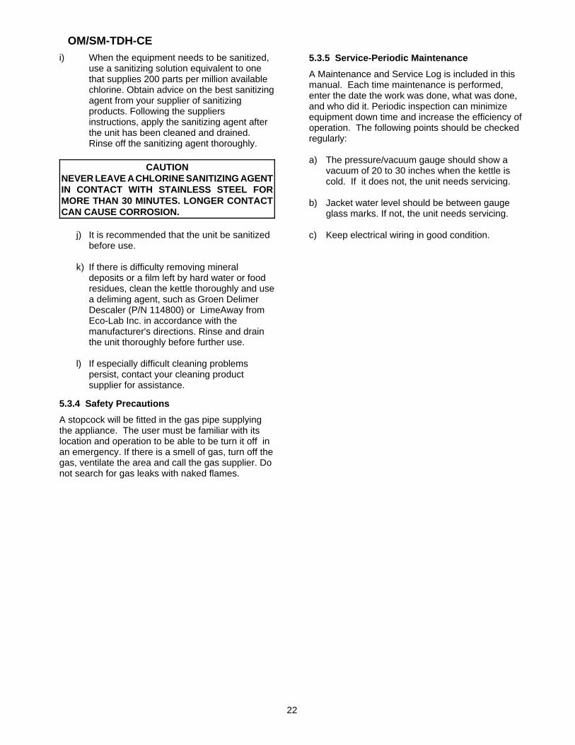
Don’t use metal implements or steel wool.
Use a brush, cloth, sponge or other non-abrasive tool for cleaning.
5.3 Cleaning and Maintenance
IMPORTANT
Disconnect the electricity supply before anycleaning is undertaken. The appliance must notbe cleaned with a jet of water nor should it besteam cleaned.
5.3.1 Suggested Tools
a) Detergent and sanitizing agent, or acombination cleaning - sanitizing agent.
b) Kettle brushes, long handled and short handled.
5.3.2 Precautions
Before cleaning operation, shut off the burner byturning the thermostat dial to "OFF". If water orcleaning/sanitizing solution will be sprayed, shut off all electric power to the unit at a remote switch suchas the circuit breaker.
WARNINGKEEP WATER AND SOLUTIONS OUT OFCONTROLS, GEARS, BURNERS, ETC. NEVERSPRAY OR HOSE THE CONTROL CONSOLE,ELECTRICAL CONNECTIONS, TILTINGMECHANISM OR CABINET.
5.3.3 Procedure
a) Clean all food contact surfaces as soon aspossible after use, preferably while the kettleis still hot. If the unit is in continuous use,thoroughly clean and sanitise both interiorand exterior at least once every 12 hours.
b) Scrape and flush out large amounts of foodresidues. Be careful not to scratch the kettlewith metal implements.
c) Prepare a hot solution of thedetergent/cleaning compound as instructedby the supplier. Clean the unit thoroughly. Acloth moistened with cleaning solution canbe used to clean controls, control housingsand electrical conduit.
d) Rinse the kettle thoroughly with hot water,then drain completely.
e) As part of the daily cleaning program, cleanall external and internal surfaces that mayhave been soiled. Remember to check suchparts as the underside of the kettle andcontrol housing.
f) To remove materials stuck to the equipment,use a brush, sponge, cloth, plastic or rubberscraper, or plastic wool with the detergentsolution. To minimize the effort required inwashing, let the detergent solution sit in thekettle and soak into the residue, or heat thedetergent solution briefly.
g) Do not use any abrasive materials or metalimplement that might scratch the surface.Scratches make the surface hard to cleanand provide places for bacteria to grow. DONOT use steel wool, which may leaveparticles imbedded in the surface and causeeventual corrosion and pitting.
h) The exterior of the unit may be polished witha recognized stainless steel cleaner or withhot water and detergent.
OM/SM-TDH-CE
22
i) When the equipment needs to be sanitized,use a sanitizing solution equivalent to onethat supplies 200 parts per million availablechlorine. Obtain advice on the best sanitizingagent from your supplier of sanitizingproducts. Following the suppliersinstructions, apply the sanitizing agent afterthe unit has been cleaned and drained.Rinse off the sanitizing agent thoroughly.
CAUTIONNEVER LEAVE A CHLORINE SANITIZING AGENTIN CONTACT WITH STAINLESS STEEL FORMORE THAN 30 MINUTES. LONGER CONTACTCAN CAUSE CORROSION.
j) It is recommended that the unit be sanitizedbefore use.
k) If there is difficulty removing mineraldeposits or a film left by hard water or foodresidues, clean the kettle thoroughly and usea deliming agent, such as Groen DelimerDescaler (P/N 114800) or LimeAway fromEco-Lab Inc. in accordance with themanufacturer's directions. Rinse and drainthe unit thoroughly before further use.
l) If especially difficult cleaning problemspersist, contact your cleaning productsupplier for assistance.
5.3.4 Safety Precautions
A stopcock will be fitted in the gas pipe supplyingthe appliance. The user must be familiar with itslocation and operation to be able to be turn it off inan emergency. If there is a smell of gas, turn off thegas, ventilate the area and call the gas supplier. Donot search for gas leaks with naked flames.
5.3.5 Service-Periodic Maintenance
A Maintenance and Service Log is included in thismanual. Each time maintenance is performed,enter the date the work was done, what was done,and who did it. Periodic inspection can minimizeequipment down time and increase the efficiency ofoperation. The following points should be checkedregularly:
a) The pressure/vacuum gauge should show avacuum of 20 to 30 inches when the kettle iscold. If it does not, the unit needs servicing.
b) Jacket water level should be between gaugeglass marks. If not, the unit needs servicing.
c) Keep electrical wiring in good condition.
OM/SM-TDH-CE
23
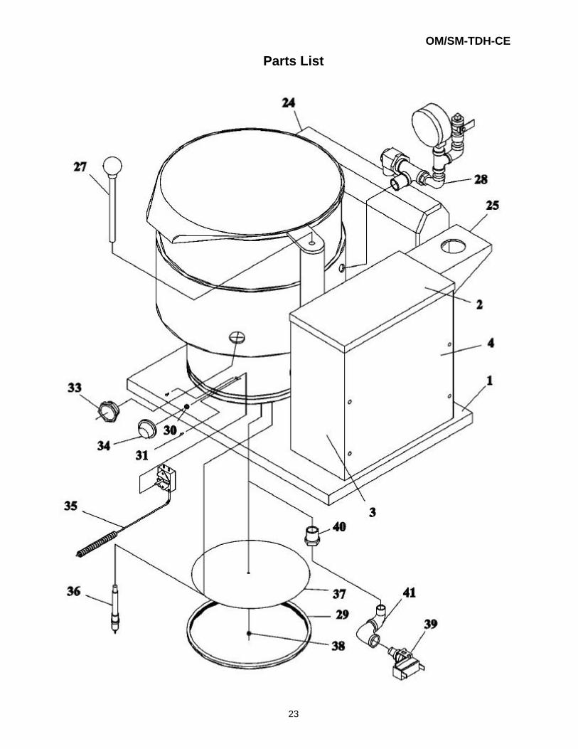
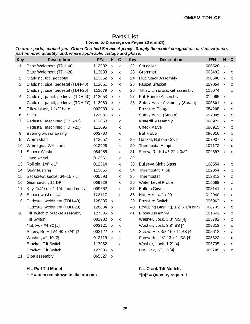
Parts List
OM/SM-TDH-CE
24PULL TILT MODELS
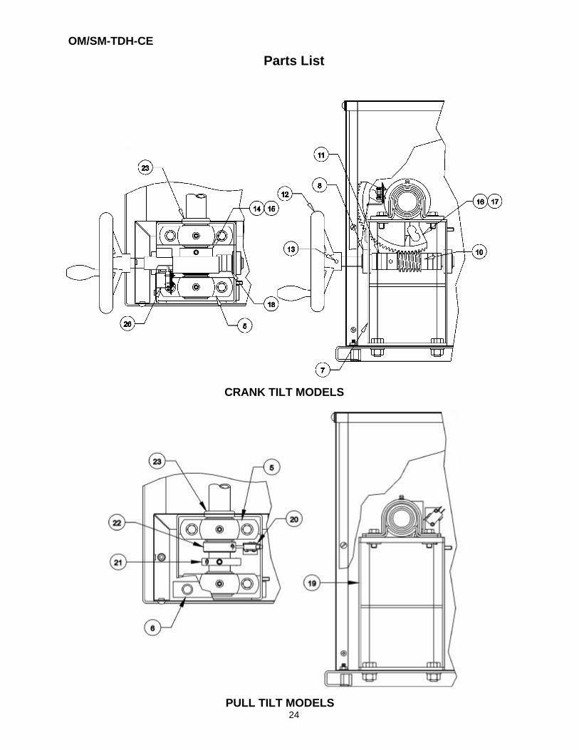
CRANK TILT MODELS
Parts List
OM/SM-TDH-CE
25
Parts List(Keyed to Drawings on Pages 23 and 24)
To order parts, contact your Groen Certified Service Agency. Supply the model designation, part description,part number, quantity, and, where applicable, voltage and phase.
Key Description P/N H C Key Description P/N H C
1 Base Weldment (TDH-40) 113082 x x 22 Set collar 065528 xBase Weldment (TDH-20) 113083 x x 23 Grommet 003492 x x
2 Cladding, top, pedestal 113052 x x 24 Flue Stack Assembly 090686 x x3 Cladding, side, pedestal (TDH-40) 113051 x x 25 Faucet Bracket 009054 x x
Cladding, side, pedestal (TDH-20) 113079 x x 26 Tilt switch & bracket assembly 113074 x4 Cladding, panel, pedestal (TDH-40) 113053 x x 27 Pull Handle Assembly 012965 x
Cladding, panel, pedestal (TDH-20) 113080 x x 28 Safety Valve Assembly (Steam) 005801 x x5 Pillow block, 1-1/2" bore 002989 x x Pressure Gauge 084208 x x6 Shim 122031 x x Safety Valve (Steam) 097005 x x7 Pedestal, machined (TDH-40) 113050 x Waterfill Assembly 096923 x x
Pedestal, machined (TDH-20) 113095 x Check Valve 096915 x x8 Bearing with snap ring 002790 x Ball Valve 096916 x x9 Worm shaft 113057 x 29 Gasket, Bottom Cover 007937 x x10 Worm gear 3/4" bore 012026 x 30 Thermostat Adapter 107172 x x11 Spacer Washer 084956 x 31 Screw, Rd Hd #6-32 x 3/8" 009697 x x12 Hand wheel 012061 x 32 --13 Roll pin, 1/4" x 1" 012614 x 33 Bullseye Sight Glass 108554 x x14 Gear bushing 113055 x 34 Thermostat Knob 122054 x x15 Set screw, socket 3/8-16 x 1" 005593 x 35 Thermostat 012313 x x16 Gear sector, 12 DP 009829 x 36 Water Level Probe 015589 x x17 Key, 1/4" sq x 1-1/4" round ends 009262 x 37 Bottom Cover 003141 x x18 Spacer washer 1/4" 122117 x 38 Nut, Hex 1/4" x 20 012940 x x19 Pedestal, weldment (TDH-40) 128835 x 39 Pressure Switch 096963 x x
Pedestal, weldment (TDH-20) 128834 x 40 Reducing Bushing, 1/2" x 1/4 NPT 008739 x x20 Tilt switch & bracket assembly 127635 x 41 Elbow Assembly 101543 x x
Tilt Switch 002982 x x Washer, Lock, 3/8" MS [4] 005702 x xNut, Hex #4-30 [2] 003121 x x Washer, Lock, 3/8" SS [4] 005618 x xScrew, Rd Hd #4-40 x 3/4" [2] 003122 x x Screw, Hex 3/8-16 x 1" SS [4] 005612 x xWasher, #4-40 [2] 013418 x x Screw Hex 1/2-13 x 1" SS [4] 005622 x xBracket, Tilt Switch 113062 x Washer, Lock, 1/2" [4] 005735 x xBracket, Tilt Switch 127636 x Nut, Hex, 1/2-13 [4] 005705 x x
21 Stop assembly 065527 x
H = Pull Tilt Model C = Crank Tilt Models
“–“ = Item not shown in illustrations “[n]” = Quantity required
OM/SM-TDH-CE
26
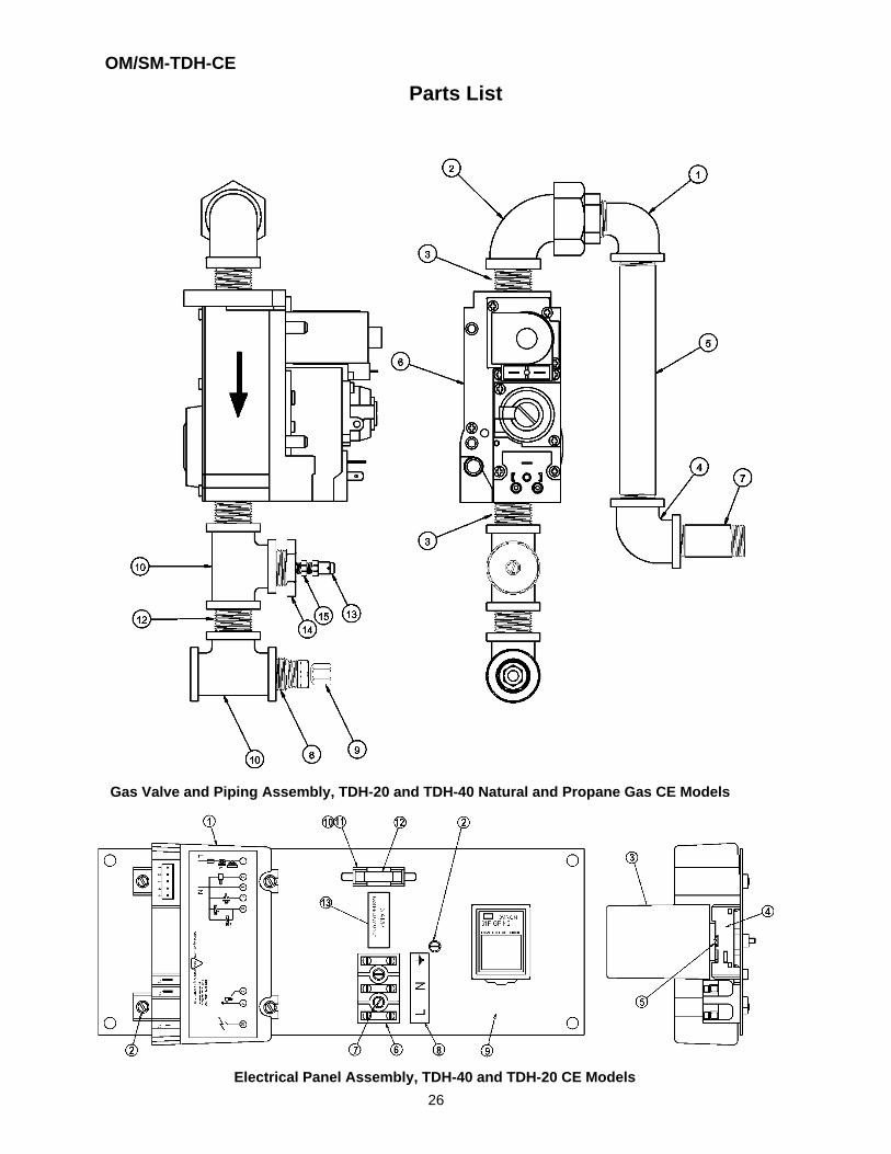
Electrical Panel Assembly, TDH-40 and TDH-20 CE Models
Gas Valve and Piping Assembly, TDH-20 and TDH-40 Natural and Propane Gas CE Models
Parts List
OM/SM-TDH-CE
27
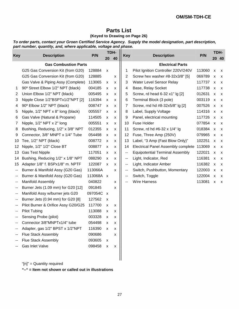
Parts List(Keyed to Drawing on Page 26)
To order parts, contact your Groen Certified Service Agency. Supply the model designation, part description,part number, quantity, and, where applicable, voltage and phase.
Key Description P/NTDH-
Key Description P/NTDH-
20 40 20 40
Gas Combustion Parts Electrical Parts
G25 Gas Conversion Kit (from G20) 128884 x 1 Pilot Ignition Controller 220V/240V 113060 x xG25 Gas Conversion Kit (from G20) 128885 x 2 Screw hex washer #8-32x3/8" [5] 069789 x xGas Valve & Piping Assy (Complete) 113065 x x 3 Water Level Sensor Relay 117737 x x
1 90º Street Elbow 1/2" NPT (black) 004185 x x 4 Base, Relay Socket 117738 x x2 Union Elbow 1/2" NPT (black) 005495 x x 5 Screw, rd head 6-32 x1" lg [2] 012631 x x3 Nipple Close 1/2"BSPTx1/2"NPT [2] 116394 x x 6 Terminal Block (3 pole) 003119 x x4 90º Elbow 1/2" NPT (black) 008747 x x 7 Screw, rnd hd #8-32x5/8" lg [2] 007526 x x5 Nipple, 1/2" NPT x 8" long (black) 005557 x x 8 Label, Supply Voltage 114316 x x6 Gas Valve (Natural & Propane) 114505 x x 9 Panel, electrical mounting 117726 x x7 Nipple, 1/2" NPT x 2" long 005551 x x 10 Fuse Holder 077854 x x8 Bushing, Reducing, 1/2" x 3/8" NPT 012355 x x 11 Screw, rd hd #6-32 x 1/4" lg 018384 x x9 Connector, 3/8" MNPT x 1/4" Tube 054498 x x 12 Fuse, Three Amp (250V) 079965 x x10 Tee, 1/2" NPT (black) 008772 x x 13 Label, “3 Amp (Fast Blow Only)” 102251 x x12 Nipple, 1/2" 1/2" Close BT 008877 x x 14 Electrical Panel Assembly complete 113069 x x13 Gas Test Nipple 117051 x x -- Equipotential Terminal Assembly 122021 x x14 Bushing, Reducing 1/2" x 1/8" NPT 088290 x x -- Light, Indicator, Red 116381 x x15 Adapter 1/8" f. BSPx1/8" m. NPTF 122087 x x -- Light, Indicator Amber 116382 x x-- Burner & Manifold Assy (G20 Gas) 113066A x -- Switch, Pushbutton, Momentary 122003 x x-- Burner & Manifold Assy (G20 Gas) 113068A x -- Switch, Toggle 122004 x x-- Manifold Assembly 040822 x -- Wire Harness 113081 x x-- Burner Jets (1.09 mm) for G20 [12] 091845 x-- Manifold Assy w/burner jets G20 097054C x-- Burner Jets (0.94 mm) for G20 [8] 127562 x-- Pilot Burner & Orifice Assy G20/G25 117700 x x-- Pilot Tubing 113088 x x-- Sensing Probe (pilot) 003328 x x-- Connector 3/8"MNPTx1/4" tube 054498 x x-- Adapter, gas 1/2" BPST x 1/2"NPT 116390 x x-- Flue Stack Assembly 090686 x-- Flue Stack Assembly 093605 x-- Gas Inlet Valve 098458 x x
“[n]” = Quantity required
“–“ = Item not shown or called out in illustrations
OM/SM-TDH-CE
28
OM/SM-TDH-CE
29
Service Log
Model m _______________________________ Purchased From _________________________
Serial m _______________________________ Location ________________________________
Date Purchased __________________________ Date Installed ___________________________
Purchase Order m ______________________ For Service Call __________________________
Date Service Performed Performed By
OM/SM-TDH-CE
30
Limited Warranty To Commercial Purchasers* (for Areas Outside of the U.S. and Canada)
Groen Foodservice Equipment ("Groen Equipment") has been skillfully manufactured, carefully inspected andpackaged to meet rigid standards of excellence. Groen warrants its Equipment to be free from defects in materialand workmanship for (12) twelve months from date of installation or (18) eighteen months from date of shipmentwith the following conditions and subject to the following limitations.
I. This parts warranty is limited to Groen Equipment sold to the original commercial purchaser. users (but notoriginal equipment manufacturers), at its original place of installation, in areas outside the U.S. andCanada.
II. Damage during shipment is to be reported to the carrier, is not covered under this warranty, and is the soleresponsibility of the purchaser/user.
III. Groen, or an authorized service representative, will repair or replace parts, at Groen's sole election, for anyGroen Equipment, including but not limited to, drawoff valves, safety valves, gas and electric components,found to be defective during the warranty period.
IV. This warranty does not cover boiler maintenance, calibration, or periodic adjustments as specified inoperating instructions or manuals, and consumable parts such as scraper blades, gaskets, packing, etc.,or labor costs incurred for removal of adjacent equipment or objects to gain access to Groen Equipment.This warranty does not cover defects caused by improper installation, abuse, careless operation, orimproper maintenance of equipment. This warranty does not cover damage caused by poor water qualityor improper boiler maintenance.
V. THIS WARRANTY IS EXCLUSIVE AND IS IN LIEU OF ALL OTHER WARRANTIES, EXPRESSED ORIMPLIED, INCLUDING ANY IMPLIED WARRANTY OF MERCHANTABILITY OR FITNESS FOR APARTICULAR PURPOSE, EACH OF WHICH IS HEREBY EXPRESSLY DISCLAIMED. THE REMEDIESDESCRIBED ABOVE ARE EXCLUSIVE AND IN NO EVENT SHALL GROEN BE LIABLE FOR SPECIAL,CONSEQUENTIAL OR INCIDENTAL DAMAGES FOR THE BREACH OR DELAY IN PERFORMANCE OFTHIS WARRANTY.
VI. Groen Equipment is for commercial use only. If sold as a component of another (O.E.M.) manufacturer'sequipment or if used as a consumer product, such Equipment is sold AS IS and without any warranty.
* (Covers All Food Service Equipment Ordered After October 1,1995)

1055 Mendell Davis DriveJackson, Mississippi 39272Telephone 601 373-3903FAX 601 373-9587
OM/SM-TDH-CEINTERNATIONAL
Part Number 128418Revised October1999