OPERATIONS MANUAL - Con-Techcon-tech.com/pdf/cs2000manual.pdf · intelligent label sensors...
18
INTELLIGENT LABEL SENSORS OPERATIONS MANUAL CS2000 & CS2000-QD CS2000 & CS2000-QD CONTROL TECHNOLOGIES www.con-tech.com
Transcript of OPERATIONS MANUAL - Con-Techcon-tech.com/pdf/cs2000manual.pdf · intelligent label sensors...

INTELLIGENT LABEL SENSORS
OPERATIONS MANUALCS2000 & CS2000-QDCS2000 & CS2000-QD
CONTROL TECHNOLOGIESwww.con-tech.com
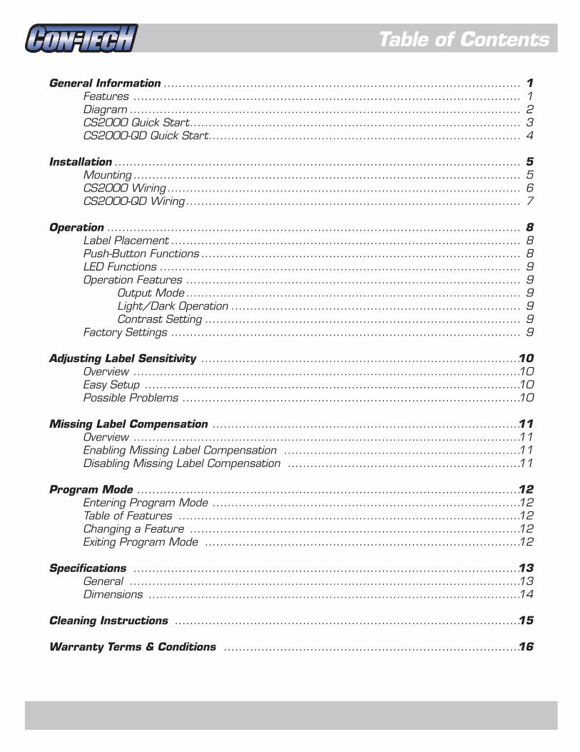
Table of Contents
General Information
Features
Diagram
CS2000 Quick Start
CS2000-QD Quick Start
Installation
Mounting
CS2000 Wiring
CS2000-QD Wiring
Operation
Label Placement
Push-Button Functions
LED Functions
Operation Features
Output Mode
Light/Dark Operation
Contrast Setting
Factory Settings
Adjusting Label Sensitivity
Overview
Easy Setup
Possible Problems
Missing Label Compensation
Overview
Enabling Missing Label Compensation
Disabling Missing Label Compensation
Program Mode
Entering Program Mode
Table of Features
Changing a Feature
Exiting Program Mode
Specifications
General
Dimensions
Cleaning Instructions
Warranty Terms & Conditions
1
1
2
3
4
5
5
6
7
8
8
8
9
9
9
9
9
9
10
10
10
10
11
11
11
11
12
12
12
12
12
13
13
14
15
16
...............................................................................................
.......................................................................................................
........................................................................................................
........................................................................................
...................................................................................
............................................................................................................
.......................................................................................................
..............................................................................................
.........................................................................................
..............................................................................................................
.............................................................................................
.....................................................................................
................................................................................................
.........................................................................................
.........................................................................................
.............................................................................
....................................................................................
.............................................................................................
.....................................................................................
.......................................................................................................
....................................................................................................
..........................................................................................
..................................................................................
.......................................................................................................
...............................................................
..............................................................
......................................................................................................
..................................................................................
...........................................................................................
........................................................................................
....................................................................................
.......................................................................................................
........................................................................................................
...................................................................................................
............................................................................................
...............................................................................
- 1 -
General Information
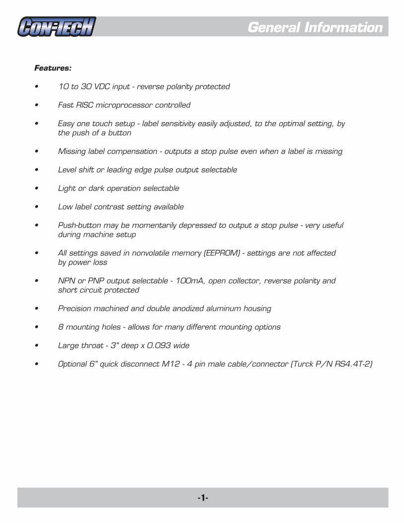
Features:
• 10 to 30 VDC input - reverse polarity protected
• Fast RISC microprocessor controlled
• Easy one touch setup - label sensitivity easily adjusted, to the optimal setting, by
the push of a button
• Missing label compensation - outputs a stop pulse even when a label is missing
• Level shift or leading edge pulse output selectable
• Light or dark operation selectable
• Low label contrast setting available
• Push-button may be momentarily depressed to output a stop pulse - very useful
during machine setup
• All settings saved in nonvolatile memory (EEPROM) - settings are not affected
by power loss
• NPN or PNP output selectable - 100mA, open collector, reverse polarity and
short circuit protected
• Precision machined and double anodized aluminum housing
• 8 mounting holes - allows for many different mounting options
• Large throat - 3" deep x 0.093 wide
• Optional 6" quick disconnect M12 - 4 pin male cable/connector (Turck P/N RS4.4T-2)

- 2 -
General Information
Yellow LED:Indicates labelbacking (web)
Push-button
Red LED:Indicates output state
Green LED:Indicates label+ label backing
Optional 6" Quick Disconnect4 Pin Male Cable/Connector
#8-32 x 0.31" DeepMounting Holes
EASY SETUP
WEB OUT LABEL
1.
2.
3.
4.
Position web under sensing area and hold button down until yellow LED comes on.Release button and yellow LED ^PSS�ÅHZO�Move label under sensing area and green LED will come on.Setup complete.
CS2000Throat
SensingArea
#8-32 x 0.31" Deep Mounting Holes (x6)
CS2000 Diagram:
- 3 -
General Information
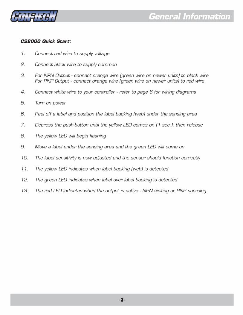
CS2000 Quick Start:
1. Connect red wire to supply voltage
2. Connect black wire to supply common
3. For NPN Output - connect orange wire (green wire on newer units) to black wire
For PNP Output - connect orange wire (green wire on newer units) to red wire
4. Connect white wire to your controller - refer to page 6 for wiring diagrams
5. Turn on power
6. Peel off a label and position the label backing (web) under the sensing area
7. Depress the push-button until the yellow LED comes on (1 sec.), then release
8. The yellow LED will begin flashing
9. Move a label under the sensing area and the green LED will come on
10. The label sensitivity is now adjusted and the sensor should function correctly
11. The yellow LED indicates when label backing (web) is detected
12. The green LED indicates when label over label backing is detected
13. The red LED indicates when the output is active - NPN sinking or PNP sourcing

- 4 -
General Information
CS2000-QD Quick Start:
1. Plug the CS2000-QD's male connector into a suitable 4 pin female connector
2. Connect brown wire to supply voltage
3. Connect blue wire to supply common
4. For NPN Output - connect black wire to blue wire
For PNP Output - connect black wire to brown wire
5. Connect white wire to your controller - refer to page 7 for wiring diagrams
6. Turn on power
7. Peel off a label and position the label backing (web) under the sensing area
8. Depress the push-button until the yellow LED comes on (1 sec.), then release
9. The yellow LED will begin flashing
10. Move a label under the sensing area and the green LED will come on
11. The label sensitivity is now adjusted and the sensor should function correctly
12. The yellow LED indicates when label backing (web) is detected
13. The green LED indicates when label over label backing is detected
14. The red LED indicates when the output is active - NPN sinking or PNP sourcing

- 5 -
Installation
Mounting:
The CS2000 comes with 8 mounting holes allowing for many different mounting options. The holes are tapped for #8-32 screws and are 0.31" deep. We suggest using #8-32 x 3/8" stainless steel screws. Some different options are shown below.
* To avoid electro-static discharge and sensor malfunction, the CS2000 should be mounted to a grounded metal surface. If this is not possible, a grounding wire should be connected from one of the mounting screws to a suitable ground.
FORK

- 6 -
Installation
CS2000 Wiring:
The CS2000 comes with an 8' - 4 conductor cable. Refer below for wire designations.
Red (RED) = 10-30 VDCBlack (BLK) = CommonWhite (WHT) = OutputOrange (ORN) or Green (GRN) = NPN / PNP Output Selector
Optoisolator
CS2000
RED
10-30V
LOAD
BLK
WHT
ORN/GRN WHT
ORN/GRN
WHT
ORN/GRN
WHT
ORN/GRN
WHT
+5V
5V Logic
1K
1/4W
Supply
Voltage
12V = 1K 1/4W
24V = 2K 1/4W
12V = 1K 1/4W
24V = 2K 1/4W
Optoisolator
*5V Com. and 10-30V Com.
must be connected together
*Output Source Com. and Supply
Com. must be connected together
*Resistor values are to source approx.
10mA to the optoisolator
*Resistor values are to source approx.
10mA to the optoisolator
ORN/GRN
WHT
ORN/GRN
CS2000
CS2000
CS2000
CS2000
CS2000
Interfacing to Load - NPN Output:
Interfacing to 5V Logic - NPN Output: Sourcing Other than Supply Voltage - PNP Output:
Interfacing to Optoisolator - PNP Output:Interfacing to Optoisolator - NPN Output:
Interfacing to Load - PNP Output:
LOAD
LOAD
RED
10-30V
RED
RED
10-30VBLK
BLK10-30V
BLK
RED
10-30VBLK
RED
BLK10-30V
Output
Source
Voltage
10-30V

- 7 -
Installation
CS2000-QD Wiring:
The CS2000-QD comes with a 6" quick disconnect M12 - 4 pin male cable/connector (Turck P/N RS4.4T-2). Refer below for wire designations.
Pin 1. Brown (BRN) = 10-30 VDCPin 2. White (WHT) = OutputPin 3. Blue (BLU) = CommonPin 4. Black (BLK) = NPN / PNP Output Selector
Optoisolator
CS2000-QD
BRN
10-30V
LOAD
BLU
WHT
BLK WHT
BLK
WHT
BLK
WHT
BLK
WHT
+5V
5V Logic
1K
1/4W
Supply
Voltage
12V = 1K 1/4W
24V = 2K 1/4W
12V = 1K 1/4W
24V = 2K 1/4W
Optoisolator
*5V Com. and 10-30V Com.
must be connected together
*Output Source Com. and Supply
Com. must be connected together
*Resistor values are to source approx.
10mA to the optoisolator
*Resistor values are to source approx.
10mA to the optoisolator
BLK
WHT
BLK
CS2000-QD
CS2000-QD
CS2000-QD
CS2000-QD
CS2000-QD
Interfacing to Load - NPN Output:
Interfacing to 5V Logic - NPN Output: Sourcing Other than Supply Voltage - PNP Output:
Interfacing to Optoisolator - PNP Output:Interfacing to Optoisolator - NPN Output:
Interfacing to Load - PNP Output:
LOAD
LOAD
BRN
10-30V
BRN
BRN
10-30VBLU
BLU10-30V
BLU
BRN
10-30VBLU
BRN
BLU10-30V
Output
Source
Voltage
10-30V
4
1
2
3
ACME LABELS
ACME LABELS
AC
ACME LABELS
ACME LABELS
ACME LABELS
ACME LABELS
- 8 -
Operation
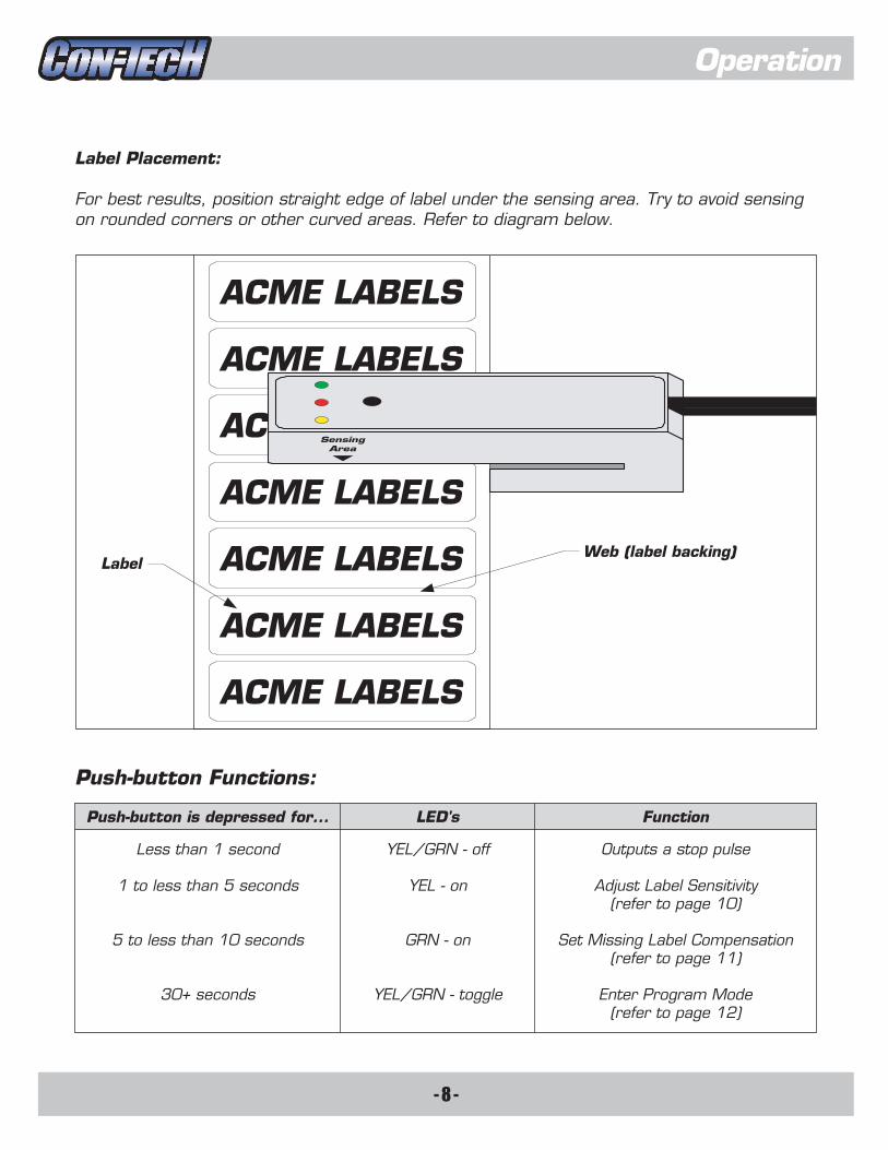
Label Placement:
For best results, position straight edge of label under the sensing area. Try to avoid sensing
on rounded corners or other curved areas. Refer to diagram below.
Less than 1 second
1 to less than 5 seconds
5 to less than 10 seconds
30+ seconds
YEL/GRN - off
YEL - on
GRN - on
YEL/GRN - toggle
Outputs a stop pulse
Adjust Label Sensitivity
(refer to page 10)
Set Missing Label Compensation
(refer to page 11)
Enter Program Mode
(refer to page 12)
Push-button is depressed for... LED's Function
Push-button Functions:
LabelWeb (label backing)
Sensing
Area

- 9 -
Operation
LED Functions:
Yellow - comes on when label backing (web) is under the sensing area
Red - comes on when output is active - NPN sinking or PNP sourcing
Green - comes on when label over label backing is under the sensing area
Operation Features:
The CS2000 has 3 different operation features that can be changed to accommodate
individual needs. They are Output Mode, Light/Dark Operation, and Contrast Setting.
Operation Features - Output Mode:
The CS2000 has 2 different output modes - Level Shift Output and Pulse Output. Level
Shift Output is either on for the length of the web, or on for the length of the label, depending
on the Light/Dark Operation setting. Pulse Output either comes on for 2 m.s. at the leading
edge of a label, or goes off for 2 m.s. at the leading edge of a label, depending on the
Light/Dark Operation setting. Refer to Program Mode (page 12) for more information.
Operation Features - Light/Dark Operation:
The CS2000 allows you the option of having the sensor's output active on the web
(Light Operate), or having the sensor's output active on the label (Dark Operate). Light Operate
is either on for the length of the web, or comes on for 2 m.s. at the leading edge of a label,
depending on the Output Mode setting. Dark Operate is either on for the length of the label, or
goes off for 2 m.s. at the leading edge of a label, depending on the Output Mode setting.
Refer to Program Mode (page 12) for more information.
Operation Features - Contrast Setting:
The CS2000 comes with a Normal Contrast Setting and a Low Contrast Setting.
Normal Contrast Setting should be fine for 99% of labels. But with labels that offer very little
contrast between the web and the label, the Low Contrast Setting can be selected very easily.
Refer to Program Mode (page 12) for more information. Adjustments to the label sensitivity
should be made more frequently when the Low Contrast Setting is selected.
*Factory Settings:
Output Mode ............................................................... Factory set to Level Shift
Light/Dark Operation.................................................... Factory set to Light
Contrast Setting........................................................... Factory set to Normal

- 10 -
Adjusting Label Sensitivity
Overview:
The CS2000 will automatically adjust its label sensitivity, to the optimal setting, by simply depressing a push-button. This adjustment process is referred to as "Easy Setup." It is recommended that the operator adjust the label sensitivity for each new roll of labels due to differences in label rolls.
Easy Setup:
To adjust label sensitivity for each new roll of labels follow steps 1-4.
1. Peel off a label and position the web (label backing) under the sensing area.
2. Depress the push-button until the yellow LED comes on (1 sec.), then release.
3. The yellow LED will begin flashing.
4. Move a label under the sensing area and the green LED will come on.
The sensor is now adjusted and should function correctly.
*Note: If in the Adjusting Label Sensitivity mode by mistake, the push-button may be depressed to exit with no changes made.
Possible Problems:
Red LED flashes after the push-button is released.
The sensor cannot adjust to the label backing. Probable cause is a build up of paper dust or some other obstruction is under the sensing area.
Blow out any paper dust present and remove any obstructions, labels, or label residue from sensing area (refer to page 15).
Symptom Problem Solution
Yellow LED continues flashing even after a label is placed under the sensing area.
There is not enough contrast between the label and the label backing.
Try the Low Contrast Setting. See Program Mode (page 12) for more information.
- 11 -
Missing Label Compensation
Overview:
The CS2000 has the capability to detect a single missing label and output a stop pulse as
though the label were present. In order for Missing Label Compensation to function properly the
operator must first: a) have Pulse Output selected - see Program Mode (page 12) for more
information. b) adjust the label sensitivity - see Easy Setup (page 10) for more information. c)
have the labeling machine set to desired speed.
Enabling Missing Label Compensation:
1. Make sure a label is under the sensing area.
2. Depress the push-button until the green LED begins flashing at a slow rate
(5 sec.), then release. If the green LED flashes at a fast rate it indicates that the
label was not positioned correctly and you need to start over.
3. Jog 1 label.
Missing Label Compensation is now enabled and should function correctly.
Disabling Missing Label Compensation:
1. Depress the push-button until the green LED begins flashing (5 sec.), then release.
2. Depress the push-button once again to disable.
*You can also disable Missing Label Compensation by selecting Level Shift Output. Refer to
Program Mode (page 12) for more information.

- 12 -
Program Mode
Entering Program Mode:
Program Mode is used to change any or all of the Operation Features. To enter Program
Mode depress the push-button until the yellow and green LED's begin toggling (30 sec.), then
release. The LED's will then output the current set-up configuration (and every 3 sec.
thereafter). For example: an output of yellow, yellow, yellow tells you that the current
configuration is Level Shift, Light Operate, and Normal Contrast Setting.
Table of Features:
Changing a Feature:
To change a feature, depress the push-button the corresponding number of times. This
will change the current feature from A to B, or from B to A. For example: If you wanted to
change the output from Level Shift to Pulse, you would depress the push-button 1 time - the
LED's would then output green, yellow, yellow. Repeat this step if you want to change more than
one feature.
Exiting Program Mode:
To exit Program Mode depress the push-button until the yellow and green LED's begin
toggling (2 sec.), then release. This puts you back in the standard operating mode.
OUTPUT MODE
LIGHT/DARK OPERATION
CONTRAST SETTING
*A. Level Shift - (default factory setting)
*A. Output on Web - Light - (default factory setting)
*A. Normal Contrast Setting - (default factory setting)
B. Low Contrast Setting
B. Output on Label - Dark
B Pulse
1
2
3
Level Shift Output
Level Shift Output
Pulse Output
Pulse Output
WEB LABEL
WEBWEB
WEB
LABEL LABEL
LABEL LABEL
LABEL
ON
ON ON
ON
ON2 m.s.
2 m.s.
OFF
OFF
OFF
OFF OFF
Yellow LED
Green LED
Green LED
Green LED
Yellow LED
Yellow LED
- 13 -
Specifications
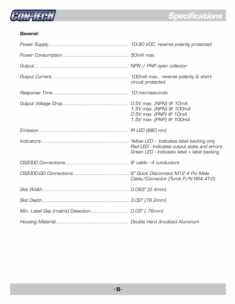
General:
Power Supply..................................................... 10-30 VDC, reverse polarity protected
Power Consumption............................................ 50mA max.
Output.............................................................. NPN / PNP open collector
Output Current................................................... 100mA max., reverse polarity & short circuit protected
Response Time.................................................. 10 microseconds
Output Voltage Drop........................................... 0.5V max. (NPN) @ 10mA 1.5V max. (NPN) @ 100mA 0.5V max. (PNP) @ 10mA 1.5V max. (PNP) @ 100mA
Emission........................................................... IR LED (880 nm)
Indicators.......................................................... Yellow LED - Indicates label backing only Red LED - Indicates output state and errors Green LED - Indicates label + label backing
CS2000 Connections.......................................... 8' cable - 4 conductors
CS2000-QD Connections..................................... 6" Quick Disconnect M12 4 Pin Male Cable/Connector (Turck P/N RS4.4T-2)
Slot Width......................................................... 0.093" (2.4mm)
Slot Depth......................................................... 3.00" (76.2mm)
Min. Label Gap (matrix) Detection......................... 0.03" (.76mm)
Housing Material................................................ Double Hard Anodized Aluminum

- 14 -
Specifications
Dimensions:
CS2000
0.4411.2
0.625
1.0025.4
0.62515.9
79.43.125
50.8
150.59
2.00
0.225.6
0.7519.1
0.5012.7
15.9
0.09
Sen
sing
Area
15.90.625
76.23.00
EASY SETUP
WEB OUT LABEL
13.50.53
1.00
88.93.50
25.4
9.50.38
2.4
1.
2.
3.
4.
Position web under sensing area and hold button down until yellow LED comes on.Release button and yellow LED ^PSS�ÅHZO�Move label under sensing area and green LED will come on.Setup complete.

- 15 -
Cleaning Instructions
Cleaning Instructions:
1. Begin by removing the sensor lid's 4 screws with a 1/16" L wrench.2. Gently lift the sensor's circuit board out by grasping the switch and pulling upward. Do not remove the insulation tape.3. Clean the lens of the sensor's photo eye with a clean soft cloth moistened with 99% isopropyl alcohol (available from most electronics supply & tool distributors - e.g. Techni- Tool, Contact East, Jensen Tools, Future Active, etc.)4. Lightly scrape off sticky label residue using an Xacto knife with a #17, #18, or #19 chisel blade. The CS2000 has double hard anodizing that is not easily penetrated, but nonetheless, care should be taken when using the Xacto knife.
5. Fold the cloth over a couple of times to make it thicker. Saturate a 2" x 2" area on the edge of the cloth with 99% isopropyl alcohol.6. Insert the wet area of the cloth into the throat of the sensor. Pull the cloth back and forth (like shining shoes) to loosen up the sticky residue.
7. Repeat steps 4 through 6 as necessary until all traces of residue have been removed.8. Insert a cotton swab dipped in 99% isopropyl alcohol into the hole on the top half of the sensor's case intended for the photo eye.9. Rub the lens of the photo emitter (located on bottom half of sensor case) with the cotton swab to remove any residue present.
10. Verify that the insulation tape is still in place and re-install the sensor's circuit board.11. Re-insert the sensor's cable into the strain relief slot located in the top/rear of the case.12. Re-install the sensor's lid making sure the cable is pinched tight and cannot be pulled out.

- 16 -
Warranty Terms & Conditions
Warranty:
The CS2000 Label Sensor is warranteed for a period of two (2) years from the time of
purchase. Control Technologies guarantees the CS2000 to be free from defects in materials
or workmanship, and that, if used correctly will perform within specifications. The warranty
covers normal wear and tear, but does not cover physical abuse, physical damage, improper
installation, or exposure to voltages greater than 35V. The warranty also does not cover
standard maintenance such as removal of paper dust, label residue build up, regular cleaning,
etc. If a CS2000 is found to be defective while still under warranty, Control Technologies will
either repair or replace the defective label sensor at our discretion. For warranty repair
service, the OEM should send defective label sensor to Control Technologies with a brief
description of the problem and sample labels if available.
Repairs:
CS2000 Label Sensors out of warranty will be repaired (if possible) at a flat rate. As of
01/01/2014 this rate is $50. For non-warranty repair service, the OEM should send
defective or damaged label sensor to Control Technologies with a brief description of the
problem and sample labels if available.
After Repair Warranty:
Upon completion of repair to CS2000 Label Sensor out of warranty, a new warranty
for a period of six (6) months will be issued.
Liability:
Control Technologies assumes no liability, in any event, for any consequential damages;
for anticipated or lost profits, incidental damages or loss of time or other losses incurred by
purchase or any third party in connection with the CS2000 Label Sensor covered by this
warranty or otherwise.


![CS2000 Review Report [final]arial 16 Report.pdf · THE LESSONS FROM CS2000 CS2000 REVIEW REPORT A report on behalf of DEFRA and CEH, NERC Compiled by Prof. David Briggs](https://static.fdocuments.in/doc/165x107/5b5baad47f8b9ac7498e841a/cs2000-review-report-final-16-reportpdf-the-lessons-from-cs2000-cs2000-review.jpg)