Operations & Maintenance Manual -...
62
Operations & Maintenance Manual 151 South Michigan Street, Seattle, Washington, USA 98108 Tel: 206-789-5410 Fax: 206-789-5414 Web: www.algas-sdi.com FILE: MANUAL PN 52642 DIRECT FIRED 7_14_14.DOC ...Innovative liquid vaporizing and gas mixing solutions LP-Gas Vaporizer: 40/40H, 80/40H & 120/60H
Transcript of Operations & Maintenance Manual -...
Operations & Maintenance Manual
151 South Michigan Street, Seattle, Washington, USA 98108 Tel: 206-789-5410 Fax: 206-789-5414 Web: www.algas-sdi.com
FILE: MANUAL PN 52642 DIRECT FIRED 7_14_14.DOC
...Innovative liquid vaporizing and gas mixing solutions
LP-Gas Vaporizer: 40/40H, 80/40H & 120/60H

WARNING
Read the OPERATION MANUAL before operating this equipment.
■ NOTE: Algas-SDI reserves the right to use alternate manufacturers’ components as vendor delivery applicability dictates. Literature contained in the Operation Manual has been supplied by vendors. Please check to be sure supplied data matches your configuration. Contact Algas-SDI if any questions exist.
■ This equipment uses LPG-a flammable fuel, handled under pressure. Inherent hazards exist and a thorough understanding of the equipment is required to allow safe operation and maintenance.
■ Allow only a TRAINED and FULLY QUALIFIED PERSON to service this equipment.
■ Any time a component must be replaced, use the same type, model, etc. DO NOT SUBSTITUTE! The consequence from such actions are unpredictable and may lead to dire consequences. When components are replaced with components not approved for use in our UL listed equipment, the UL listing becomes void for that unit.
Warranty, Copyrights and Approvals
WARRANTY
Algas-SDI International, LLC (ASDI) warrants that the equipment is free of defects in materials and workmanship under normal use and service. ASDI agrees to repair or replace, at our option, without charge f.o.b. factory, any part which has proven defective to the satisfaction of Algas-SDI International, LLC within one (1) year from the date of the original installation or within 18 months from the date of shipment, whichever is earlier. Equipment, which in the opinion of ASDI, has been damaged by improper installation or operation, or has been abused or tampered with in any way, will not be accepted for return under warranty.
Algas-SDI International, LLC will not accept back charges for work performed by others upon or in conjunction with ASDI equipment, unless prior authorization is given by means of an Algas-SDI International, LLC purchase order. Algas-SDI International, LLC will not be liable by reason of shutdown, non-operation or increased expense of operation of other equipment, or any other loss or damage of any nature, whether direct or consequential, arising from any cause whatsoever.
Algas-SDI International, LLC makes NO other warranty of any kind, whatsoever expressed or implied; and all warranties of merchantability and fitness for a particular purpose are hereby disclaimed by Algas-SDI International, LLC and excluded from these terms of sale. No person has any authority to bind Algas-SDI International, LLC to any representation or warranty other than this warranty.
COPYRIGHT
Copyright 2014 by Algas-SDI International, LLC, Seattle, Washington 98108. All rights reserved. No part of this manual may be reproduced or copied in any form or by any means, photographic, electronic, or mechanical, without the prior express written consent from Algas-SDI International, LLC, Seattle, Washington, USA.
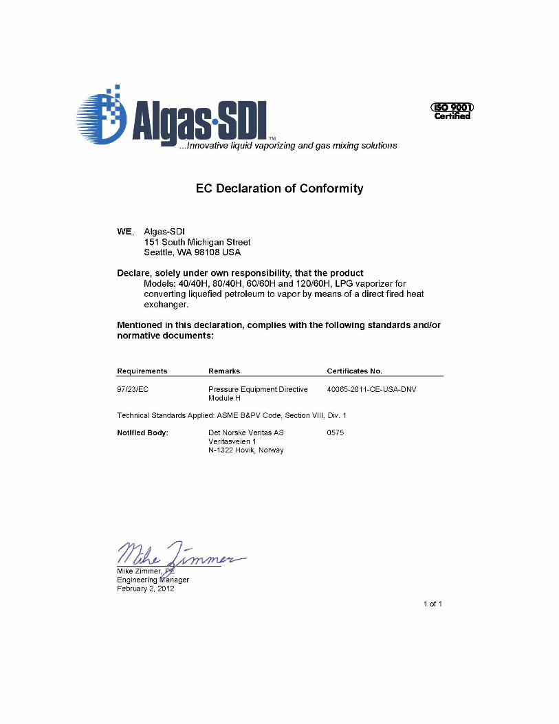
APPROVALS

This page left intentionally blank
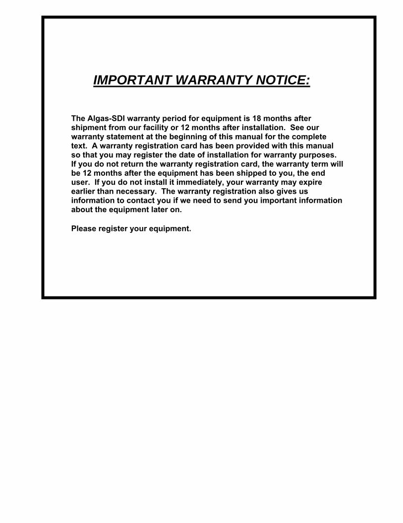
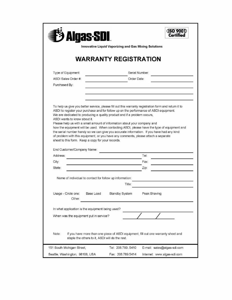
IMPORTANT WARRANTY NOTICE:
The Algas-SDI warranty period for equipment is 18 months after shipment from our facility or 12 months after installation. See our warranty statement at the beginning of this manual for the complete text. A warranty registration card has been provided with this manual so that you may register the date of installation for warranty purposes. If you do not return the warranty registration card, the warranty term will be 12 months after the equipment has been shipped to you, the end user. If you do not install it immediately, your warranty may expire earlier than necessary. The warranty registration also gives us information to contact you if we need to send you important information about the equipment later on.
Please register your equipment.
Symbols and Conventions
Special symbols are used to denote hazardous or important information. You should familiarize yourself with their meaning and take special notice of the indicated information.
Please read the following explanations thoroughly.
GENERAL WARNING OR CAUTION
Indicates hazards or unsafe practices which can result in damage to the equipment or cause personal injury. Use care and follow the instructions given.
FLAMMABLE GAS HAZARD
Indicates a potential hazard which can result in severe personal injury or death. Use extreme care and follow the instructions given.
ELECTRICAL DISCONNECT REQUIRED
Indicates a potentially dangerous situation which can result in severe personal injury or death or damage to equipment. Use great care and follow the instruction given.
PARTS AND PRICES
For parts and prices contact your Algas-SDI distributor.
ASDI CONTACT NUMBERS
If you have questions, need help with your equipment, or want information on other products, contact your distributor or Algas-SDI at: Telephone: 206.789.5410 Facsimile: 206.789.5414 Email: [email protected] Internet: http://www.algas-sdi.com

This page left intentionally blank
Table of Contents
Options
Auto Re-igniter
Contaminant Separator / Filtaire
Economy Kit
Inlet and Outlet Hand Valves
Pipe away Adapter
1st Stage Regulator
1. Introduction
Description/Overview 1-1
Figure 1 – Direct Fired Vaporizer System - Basic Features 1-1
How the vaporizer works 1-2
Direct fired vaporizer specifications 1-3
2. Installation
General 2-4
Unpacking and Initial Assembly 2-4
Unpacking 2-4
Initial Assembly 2-4
Table 1 – Distance from Vaporizer 2-4
Figure 2 – Vaporizer Dimensions 2-5
Figure 3 – Installation – 40/40H, 80/40H, and 120/60H vaporizers 2-6
Vapor Distribution Line 2-6
Table 2 – Recommended Vapor Distribution Line Size 2-6
Liquid Inlet 2-7
Vapor Bypass Line (Optional) 2-7
Burner Supply Line (Optional) 2-7
Liquid Pump (Optional) 2-8
Economy Installation (Optional) 2-8
Figure 4 – Economy Option 2-8
Contaminant Separator – Filtaire (Optional) 2-9
Figure 5 – Filtaire Operation 2-9
Installing Multiple Units in Parallel 2-10
Figure 6 – Installing Multiple Units in Parallel 2-10
Figure 7 – Installing Multiple Units in Parallel, Oversized Manifolds 2-10
Leak Test 2-11
Check Burner Input Pressure 2-11
3. Operation
Direct Fired Vaporizer start up procedure 3-13
Figure 8 – Temperature control dial in “RUN” position 3-13
Figure 9 – Pilot button pressed down and ignitor switch on 3-14
Direct Fired Vaporizer setpoint adjustment 3-14
Figure 10 – Rotating temperature control dial counter-clockwise to desired setpoint 3-14
Direct Fired Vaporizer shutdown procedure 3-15
Figure 11 – Vaporizer shut down procedure 3-15
Direct fired vaporizer purge procedure 3-16
Automatic Re-Ignition Operation 3-16
Economy Operation 3-16
4. Maintenance
Service and Maintenance 4-18
Table 3 – commended periodic maintenance and inspections 4-18
Table 4 – Recommended annual maintenance and inspections 4-19
Direct Fired vaporizer inspection checklist 4-21
Replacing reignitor battery 4-22
Figure 12 – Opening the battery access door 4-22
Figure 13 – Replacing the battery 4-22
Adjusting burner input pressure 4-23
Error! Reference source not found. 4-23
Liquid inlet valve maintenance procedure 4-24
Capacity control valve maintenance procedure 4-26
5. Troubleshooting
Pilot 5-28
Main Burner Will Not Ignite 5-28
If Vapor Pressure Drops 5-28
Troubleshooting Tree #1: Pilot Will Not Light 5-29
Troubleshooting Tree #2: Pilot Lights But Will Not Hold 5-30
Troubleshooting Tree #3: Main Burner Will Not Light 5-31
Troubleshooting Tree #4: Vapor Service Pressure Drops 5-32
Appendix A: Technical Information
Figure 14 – 40/40H Vaporizer Replacement Parts A-36
Figure 15 – 80/40H and 120/60H Vaporizer Replacement Parts A-37
Figure 16 – Inlet Valve and Capacity Control Valve A-38
Table 5 – Repair kits and other available replacement parts A-40
Liquid Inlet valve pin gasket installation procedure A-43

This page left intentionally blank
Options Auto Re-igniter
40/40H, 80/40H & 120/60H, Auto Re-igniter System 115/230 VAC 50/60Hz, Use P/N: 3-8683, Quantity 1 per unit
See Page 3-16 for Details
Contaminant Separator / Filtaire
40/40H, 80/40H, Filtaire Model F4, Use P/N: 20536 or 20536-ASME, Quantity 1 per unit
120/60H, Filtaire Model F6, Use P/N: 20540 or 20540-ASME, Quantity 1 per unit
See Page 2-9 for Details
Economy Kit
40/40H, 80/40H & 120/60H, Economy Option Kit P/N: 80793, Quantity 1 per unit,
See Page 2-8 and 3-16 for Details
Inlet and Outlet Isolation Valves
40/40H, 80/40H & 120/60H, 3/4" inlet valve use P/N 33803, Quantity 1 per unit
40/40H, 80/40H & 120/60H, 1" outlet valve use P/N 33814, Quantity 1 per unit
Pipeaway Adapter
40/40H, 80/40H & 120/60H, Pipeaway Adapter 3/4", Quantity 1 per unit
Use P/N 1501-5016 for Cavagna/Omeca relief valve
Use P/N 34877 for REGO relief valve
1st Stage Regulator
40/40H, 80/40H & 120/60H, 1" 5-20 PSIG, Use P/N: 33725, Quantity 1 per unit
Algas-SDI Operation and Maintenance Manual – P/N – 52642 1-1
Introduction 1 Description/Overview
Congratulations on your purchase of an Algas-SDI Direct Fired vaporizer. Algas-SDI is an ISO 9001 registered company and your new vaporizer was manufactured under strict accordance with ASME and UL requirements and carries the associated marks and the ASME "U" stamp.
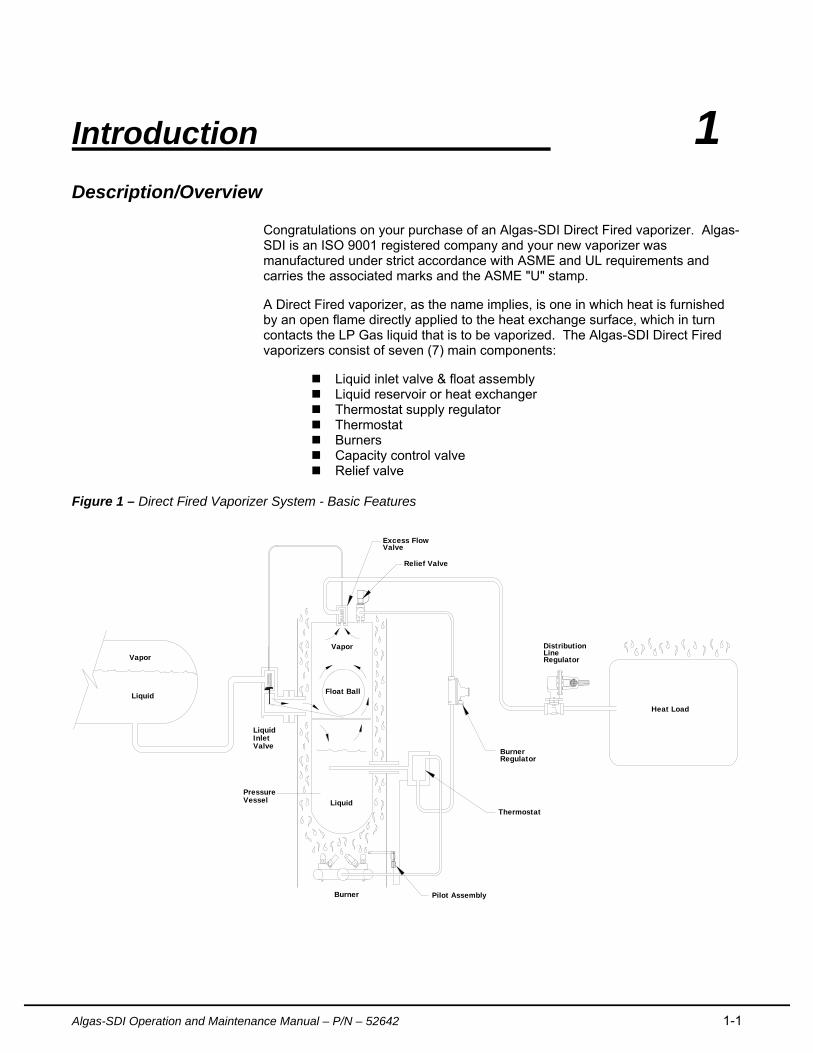
A Direct Fired vaporizer, as the name implies, is one in which heat is furnished by an open flame directly applied to the heat exchange surface, which in turn contacts the LP Gas liquid that is to be vaporized. The Algas-SDI Direct Fired vaporizers consist of seven (7) main components:
Liquid inlet valve & float assembly Liquid reservoir or heat exchanger Thermostat supply regulator Thermostat Burners Capacity control valve Relief valve
Figure 1 – Direct Fired Vaporizer System - Basic Features
Vapor
Liquid
LiquidInletValve
VesselPressure
Liquid
Burner Pilot Assembly
Float Ball
BurnerRegulator
Excess FlowValve
Relief Valve
Vapor DistributionLineRegulator
Heat Load
Thermostat
Introduction
1-2 Algas-SDI Operation and Maintenance Manual – P/N - 52642
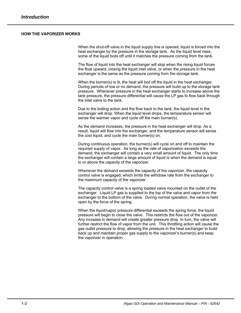
HOW THE VAPORIZER WORKS
When the shut-off valve in the liquid supply line is opened, liquid is forced into the heat exchanger by the pressure in the storage tank. As the liquid level rises, some of the liquid boils off until it matches the pressure coming from the tank.
The flow of liquid into the heat exchanger will stop when the rising liquid forces the float upward, closing the liquid inlet valve, or when the pressure in the heat exchanger is the same as the pressure coming from the storage tank.
When the burner(s) is lit, the heat will boil off the liquid in the heat exchanger. During periods of low or no demand, the pressure will build up to the storage tank pressure. Whenever pressure in the heat exchanger starts to increase above the tank pressure, the pressure differential will cause the LP gas to flow back through the inlet valve to the tank.
Due to the boiling action and the flow back to the tank, the liquid level in the exchanger will drop. When the liquid level drops, the temperature sensor will sense the warmer vapor and cycle off the main burner(s).
As the demand increases, the pressure in the heat exchanger will drop. As a result, liquid will flow into the exchanger, and the temperature sensor will sense the cool liquid, and cycle the main burner(s) on.
During continuous operation, the burner(s) will cycle on and off to maintain the required supply of vapor. As long as the rate of vaporization exceeds the demand, the exchanger will contain a very small amount of liquid. The only time the exchanger will contain a large amount of liquid is when the demand is equal to or above the capacity of the vaporizer.
Whenever the demand exceeds the capacity of the vaporizer, the capacity control valve is engaged, which limits the withdraw rate from the exchanger to the maximum capacity of the vaporizer.
The capacity control valve is a spring loaded valve mounted on the outlet of the exchanger. Liquid LP gas is supplied to the top of the valve and vapor from the exchanger to the bottom of the valve. During normal operation, the valve is held open by the force of the spring.
When the liquid/vapor pressure differential exceeds the spring force, the liquid pressure will begin to close the valve. This restricts the flow out of the vaporizer. Any increase in demand will create greater pressure drop. In turn, the valve will further restrict the flow of vapor from the unit. This throttling action will cause the gas outlet pressure to drop, allowing the pressure in the heat exchanger to build back up and maintain proper gas supply to the vaporizer’s burner(s) and keep the vaporizer in operation.
Introduction
Algas-SDI Operation and Maintenance Manual – P/N – 52642 1-3
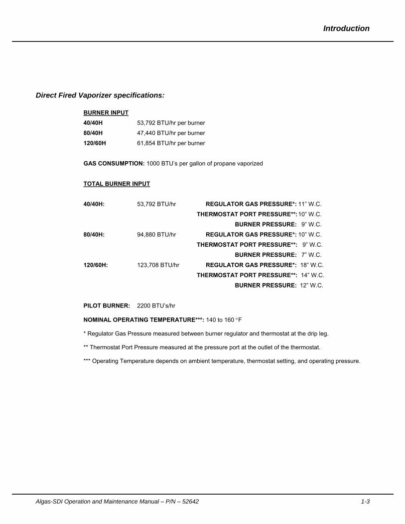
Direct Fired Vaporizer specifications:
BURNER INPUT
40/40H 53,792 BTU/hr per burner
80/40H 47,440 BTU/hr per burner
120/60H 61,854 BTU/hr per burner
GAS CONSUMPTION: 1000 BTU’s per gallon of propane vaporized
TOTAL BURNER INPUT
40/40H: 53,792 BTU/hr REGULATOR GAS PRESSURE*: 11” W.C.
THERMOSTAT PORT PRESSURE**: 10” W.C.
BURNER PRESSURE: 9” W.C.
80/40H: 94,880 BTU/hr REGULATOR GAS PRESSURE*: 10” W.C.
THERMOSTAT PORT PRESSURE**: 9” W.C.
BURNER PRESSURE: 7” W.C.
120/60H: 123,708 BTU/hr REGULATOR GAS PRESSURE*: 18” W.C.
THERMOSTAT PORT PRESSURE**: 14” W.C.
BURNER PRESSURE: 12” W.C.
PILOT BURNER: 2200 BTU’s/hr NOMINAL OPERATING TEMPERATURE***: 140 to 160 F * Regulator Gas Pressure measured between burner regulator and thermostat at the drip leg. ** Thermostat Port Pressure measured at the pressure port at the outlet of the thermostat. *** Operating Temperature depends on ambient temperature, thermostat setting, and operating pressure.
2-4 Algas-SDI Operation and Maintenance Manual – P/N – 52642
Installation 2
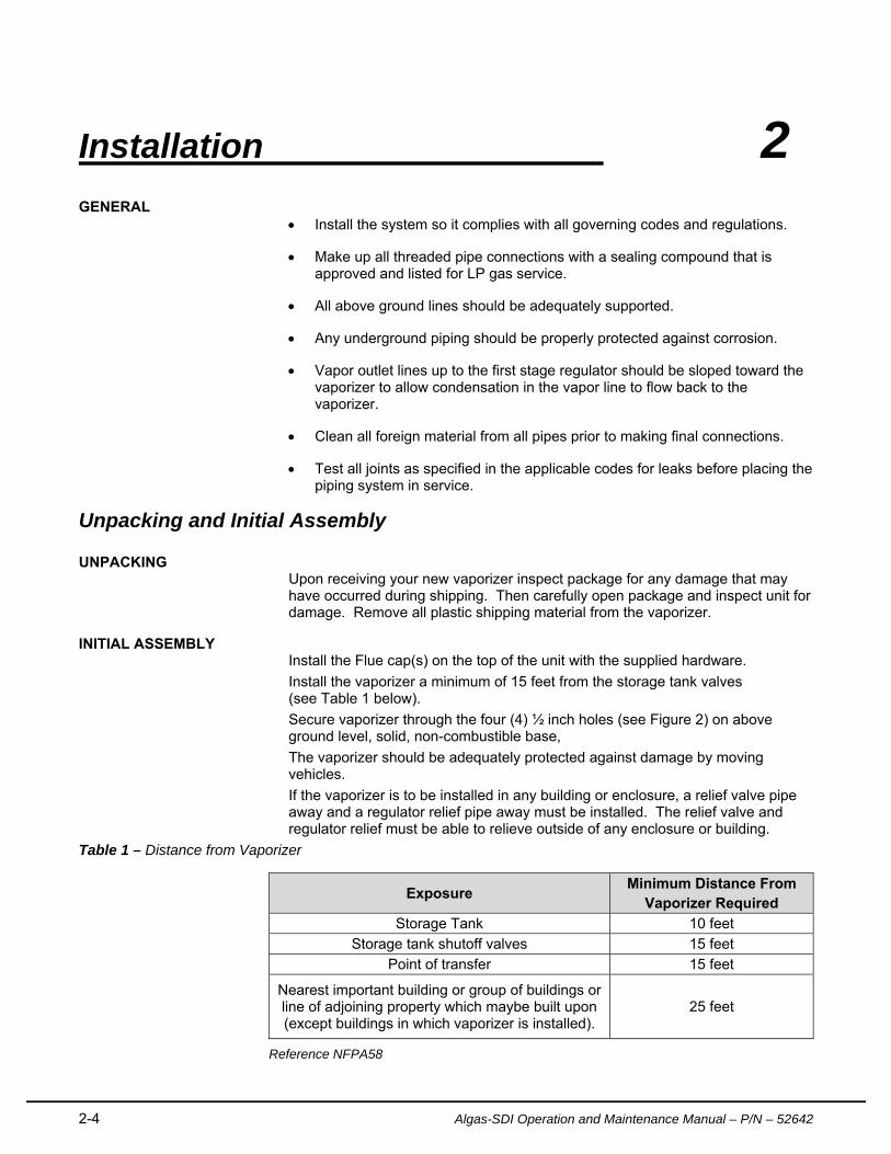
GENERAL Install the system so it complies with all governing codes and regulations.
Make up all threaded pipe connections with a sealing compound that is approved and listed for LP gas service.
All above ground lines should be adequately supported.
Any underground piping should be properly protected against corrosion.
Vapor outlet lines up to the first stage regulator should be sloped toward the vaporizer to allow condensation in the vapor line to flow back to the vaporizer.
Clean all foreign material from all pipes prior to making final connections.
Test all joints as specified in the applicable codes for leaks before placing the piping system in service.
Unpacking and Initial Assembly
UNPACKING Upon receiving your new vaporizer inspect package for any damage that may have occurred during shipping. Then carefully open package and inspect unit for damage. Remove all plastic shipping material from the vaporizer.
INITIAL ASSEMBLY Install the Flue cap(s) on the top of the unit with the supplied hardware.
Install the vaporizer a minimum of 15 feet from the storage tank valves (see Table 1 below).
Secure vaporizer through the four (4) ½ inch holes (see Figure 2) on above ground level, solid, non-combustible base,
The vaporizer should be adequately protected against damage by moving vehicles.
If the vaporizer is to be installed in any building or enclosure, a relief valve pipe away and a regulator relief pipe away must be installed. The relief valve and regulator relief must be able to relieve outside of any enclosure or building.
Table 1 – Distance from Vaporizer
Exposure Minimum Distance From
Vaporizer Required
Storage Tank 10 feet
Storage tank shutoff valves 15 feet
Point of transfer 15 feet
Nearest important building or group of buildings or line of adjoining property which maybe built upon (except buildings in which vaporizer is installed).
25 feet
Reference NFPA58
Installation
Algas-SDI Operation and Maintenance Manual – P/N – 52642 2-5
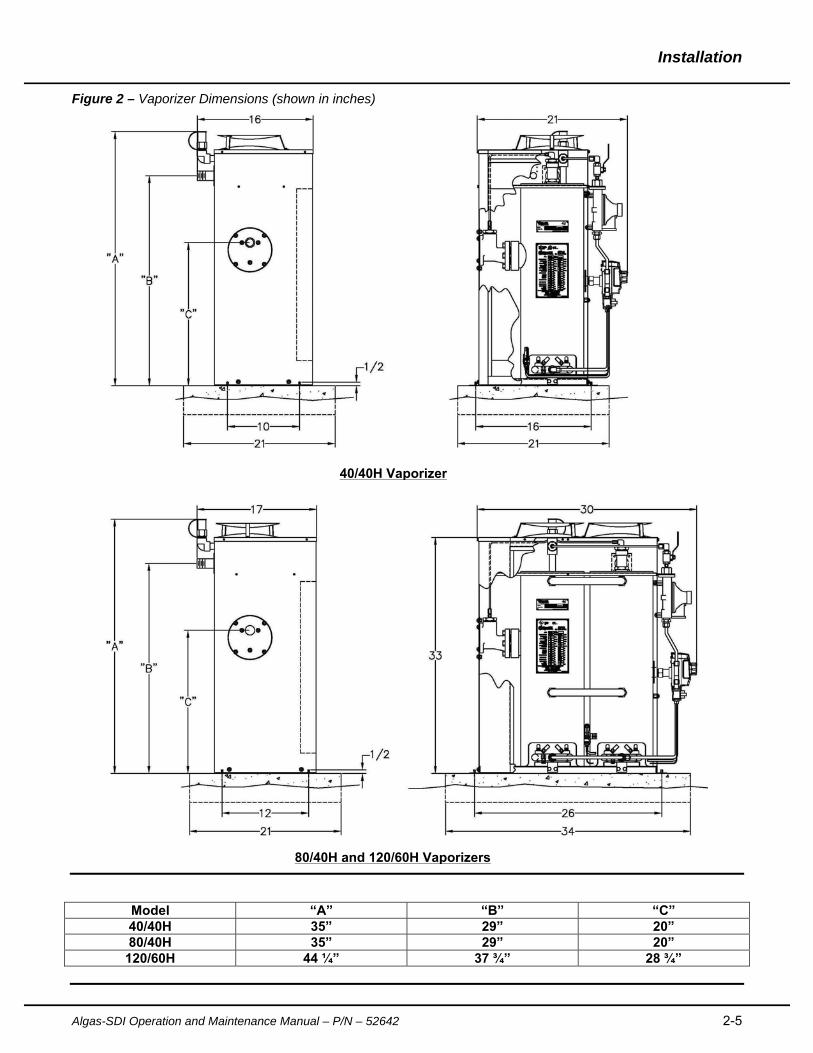
Figure 2 – Vaporizer Dimensions (shown in inches)
Model “A” “B” “C” 40/40H 35” 29” 20” 80/40H 35” 29” 20”
120/60H 44 ¼” 37 ¾” 28 ¾”
40/40H Vaporizer
80/40H and 120/60H Vaporizers
Installation
2-6 Algas-SDI Operation and Maintenance Manual – P/N - 52642
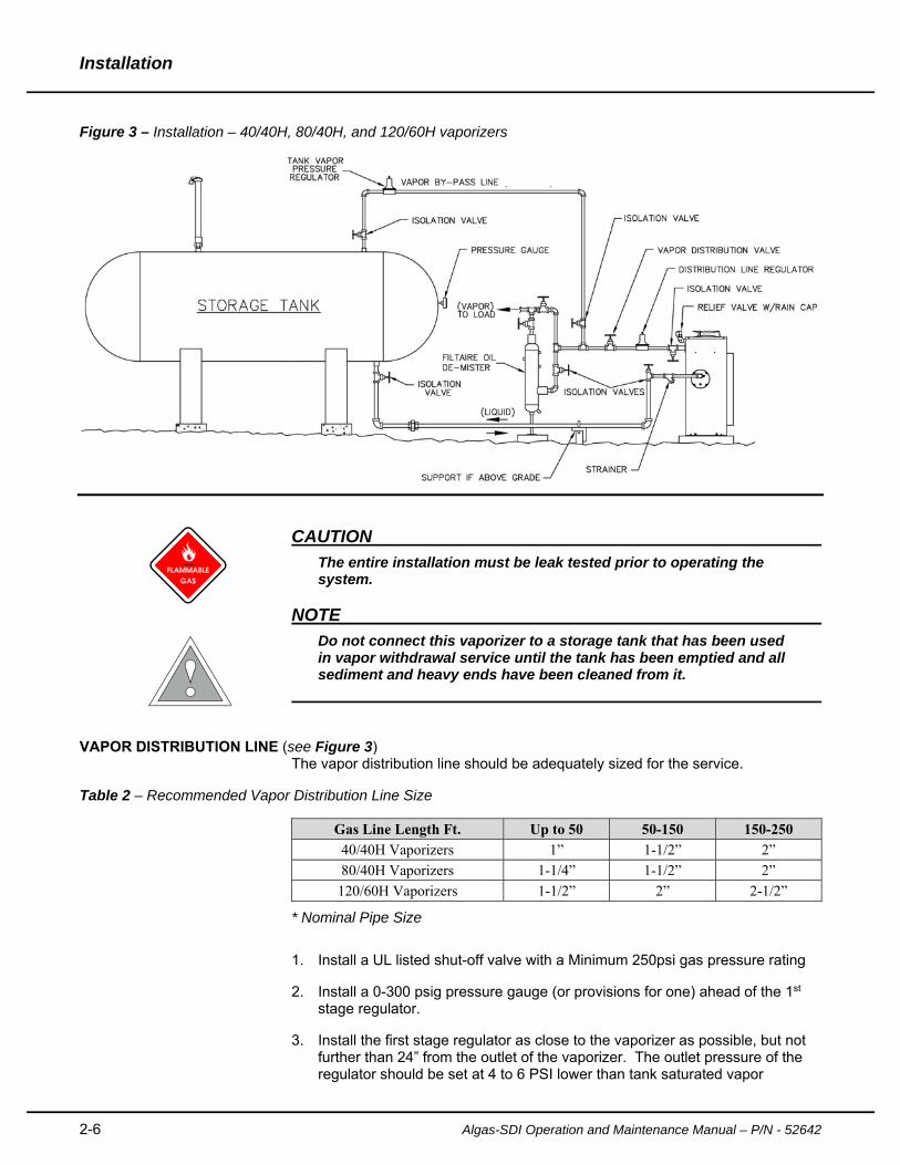
Figure 3 – Installation – 40/40H, 80/40H, and 120/60H vaporizers
CAUTION
The entire installation must be leak tested prior to operating the system.
NOTE
Do not connect this vaporizer to a storage tank that has been used in vapor withdrawal service until the tank has been emptied and all sediment and heavy ends have been cleaned from it.
VAPOR DISTRIBUTION LINE (see Figure 3)
The vapor distribution line should be adequately sized for the service.
Table 2 – Recommended Vapor Distribution Line Size
Gas Line Length Ft. Up to 50 50-150 150-250
40/40H Vaporizers 1” 1-1/2” 2”
80/40H Vaporizers 1-1/4” 1-1/2” 2”
120/60H Vaporizers 1-1/2” 2” 2-1/2”
* Nominal Pipe Size
1. Install a UL listed shut-off valve with a Minimum 250psi gas pressure rating
2. Install a 0-300 psig pressure gauge (or provisions for one) ahead of the 1st stage regulator.
3. Install the first stage regulator as close to the vaporizer as possible, but not further than 24” from the outlet of the vaporizer. The outlet pressure of the regulator should be set at 4 to 6 PSI lower than tank saturated vapor
Installation
Algas-SDI Operation and Maintenance Manual – P/N – 52642 2-7
pressure at lowest expected temperature; this may require periodic adjustment.
4. The second stage (or low pressure) regulator should be installed as close to the consuming equipment as practical.
5. A line relief valve may be installed (optional) to protect the regulators from excessively high pressure. If a line relief valve is used, set the blow pressure at approximately 10 PSI above the first stage regulator delivery pressure.
LIQUID INLET NOTE
Do not install a check valve in the supply line between the tank and the vaporizer. Liquid must be able to flow both ways in that line.
1. Install the 60-mesh 3/4" strainer that is supplied with the unit on the liquid inlet to the vaporizer.
2. Install a UL listed shut-off valve with a Minimum 250psig gas pressure rating
3. Install a 0-300 psig pressure gauge (or provisions for one) ahead of the liquid inlet valve.
4. The liquid line from the storage tank to the vaporizer should be of sufficient size to supply the vaporizer at full capacity with a maximum pressure drop of less than the hydrostatic head pressure (see NFPA 54).
5. Connect the vaporizer to the storage tank.
VAPOR BYPASS LINE - see Figure 3
1. Install a primary (first stage) regulator at the vapor outlet on top of the storage tank. Set this regulator to deliver gas at a pressure of 2 to 4 psi below the setting of the vaporizer regulator. Then if the vaporizer is overloaded or its output pressure drops off, the regulator on top of the storage tank will automatically take over.
2. Run a line from the regulator and tie it into the vapor service line downstream from the vaporizer first stage regulator.
3. Although vapor bypass line is not required for proper operation, it is recommended for all installations.
BURNER SUPPLY LINE (OPTIONAL)
The vaporizer burners are supplied with vapor from the outlet of the vaporizer where the least possibility of condensation will take place. In regions where there is a problem with a high content of heavy ends in the LP gas, a separate vapor supply line to the burner control on the vaporizer may be installed. If a separate burner supply line is used, the following is recommended:
1. Disconnect the ¼” line at the burner regulator inlet.
2. Disconnect the ¼” line at the tee on top of the heat exchanger and plug it with ¼-NPT plug.
Installation
2-8 Algas-SDI Operation and Maintenance Manual – P/N - 52642
3. Install a first stage regulator as close to the tank vapor outlet as possible. A manual shut-off valve should be installed ahead of the regulator.
4. Connect the supply line from the first stage regulator to the burner regulator at the vaporizer. Make sure that the supply is sized properly to handle maximum input rating of the vaporizer burner(s). See Figure 1.
5. For the 40/40H, 80/40H and 120/60H Thermostat Supply Regulator pressure adjustments please refer to page 1-3.
LIQUID PUMP (OPTIONAL)
The liquid pressure to the inlet of the vaporizer must be a minimum of 6PSI higher than desired discharge pressure. If tank pressure cannot meet this requirement, install a pump in the liquid line under the storage tank to maintain the minimum pressure.
ECONOMY INSTALLATION (OPTIONAL)
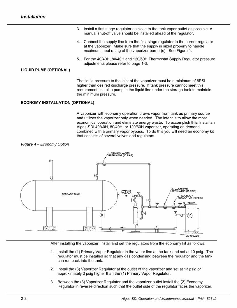
A vaporizer with economy operation draws vapor from tank as primary source and utilizes the vaporizer only when needed. The intent is to allow the most economical operation and eliminate energy waste. To accomplish this, install an Algas-SDI 40/40H, 80/40H, or 120/60H vaporizer, operating on demand, combined with a primary vapor bypass. To do this you will need an economy kit that consists of several valves and regulators.
Figure 4 – Economy Option
After installing the vaporizer, install and set the regulators from the economy kit as follows:
1. Install the (1) Primary Vapor Regulator in the vapor line at the tank and set at 10 psig. The regulator must be installed so that any gas condensing between the regulator and the tank can run back into the tank.
2. Install the (3) Vaporizer Regulator at the outlet of the vaporizer and set at 13 psig or approximately 3 psig higher than the (1) Primary Vapor Regulator.
3. Between the (3) Vaporizer Regulator and the vaporizer outlet install the (2) Economy Regulator in reverse direction such that the outlet side of the regulator faces the vaporizer.

Installation
Algas-SDI Operation and Maintenance Manual – P/N – 52642 2-9
This regulator should be set at 30 psig or just high enough to allow enough pressure in the tank to supply the full flow through the (3) Vaporizer Regulator when needed.
CONTAMINANT SEPARATOR – FILTAIRE (OPTIONAL)
The FILTAIRE is a filtering device designed to trap heavy hydrocarbons commonly present in LPG gas vapor. It also traps other materials, which may be in the gas due to storage conditions and internal condition of the equipment.
Impurities are collected in the system and periodically removed through the system blow down drain. Residual heavy end hydrocarbons with boiling points higher than pure LPG are trapped by the filter and fall to the bottom for removal.
A complete FILTAIRE system consists of inlet and outlet connections, a blow-down drain (5), a pressure gauge (4), a vent which is normally plugged (6), and a bypass valve system for cleaning (1, 2, and 3). The bypass valves enable the system to continue operating when the FILTAIRE is removed for cleaning (see
Figure 5).
At 20 psig, recommend using Algas-SDI FILTAIRE Model F4 ASDI PN: 20536 or 20536-ASME for Direct Fired Models 40/40H, and 80/40H. At 20 psig recommend using Algas-SDI FILTAIRE Model F6 ASDI PN: 20540 or 20540-ASME for Direct Fired Model 120/60H.
Note: Items 4, 5 and 6 are included with FILTAIRE assemblies.
Figure 5 – Filtaire Operation
1ST STAGEREGULATOR
VAPOR FROMVAPORIZER
INLET VALVE2
VAPOR LINE
“FILTAIRE” OIL DEMISTER
OUTLET VALVE
BYPASS VALVE(NORMALLY CLOSED)
3
1
5 DRAINVALVE
PIPESTAND
64
VAPORTO LOAD
Installation
2-10 Algas-SDI Operation and Maintenance Manual – P/N - 52642
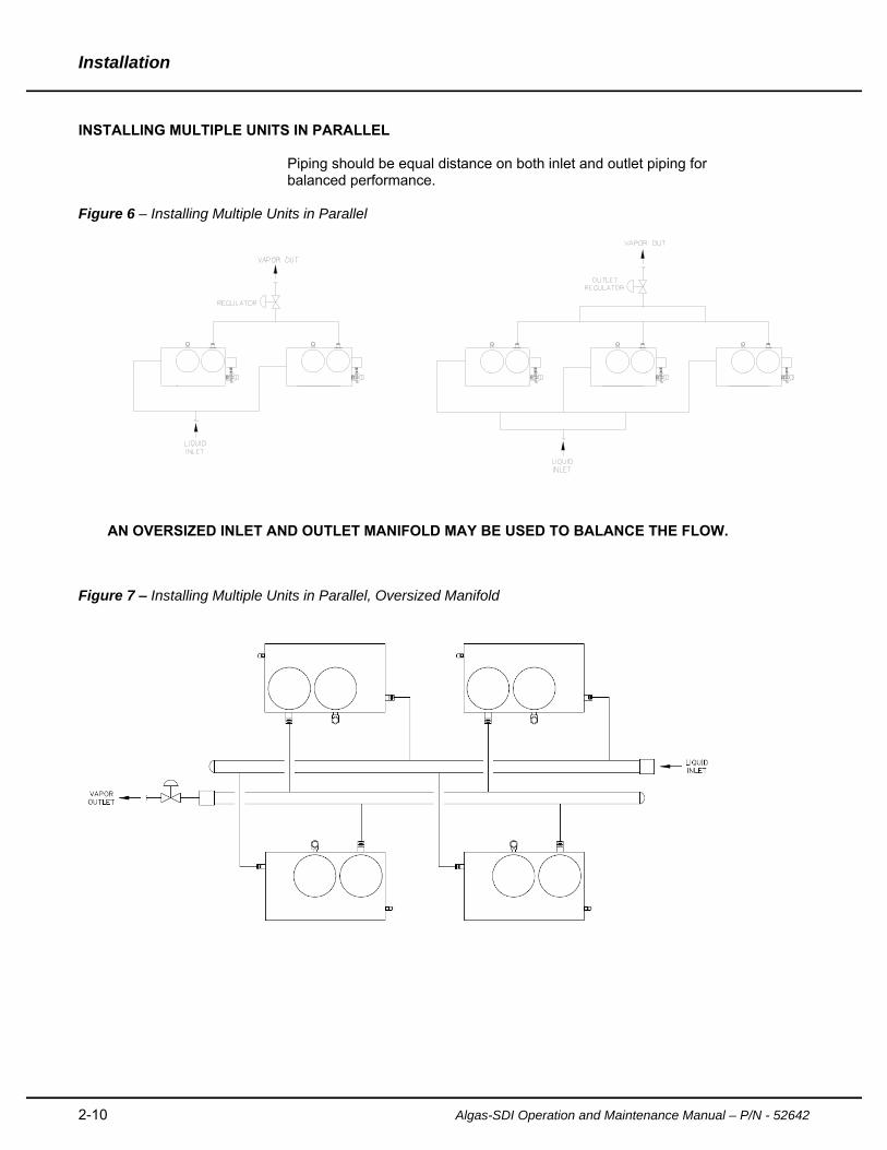
INSTALLING MULTIPLE UNITS IN PARALLEL Piping should be equal distance on both inlet and outlet piping for balanced performance.
Figure 6 – Installing Multiple Units in Parallel
AN OVERSIZED INLET AND OUTLET MANIFOLD MAY BE USED TO BALANCE THE FLOW.
Figure 7 – Installing Multiple Units in Parallel, Oversized Manifold
Installation
Algas-SDI Operation and Maintenance Manual – P/N – 52642 2-11
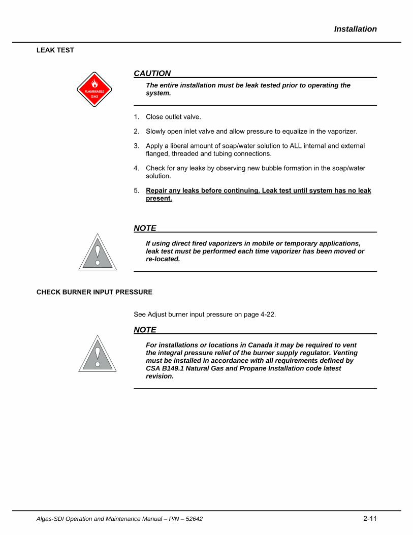
LEAK TEST
CAUTION
The entire installation must be leak tested prior to operating the system.
1. Close outlet valve.
2. Slowly open inlet valve and allow pressure to equalize in the vaporizer.
3. Apply a liberal amount of soap/water solution to ALL internal and external flanged, threaded and tubing connections.
4. Check for any leaks by observing new bubble formation in the soap/water solution.
5. Repair any leaks before continuing. Leak test until system has no leak present.
NOTE
If using direct fired vaporizers in mobile or temporary applications, leak test must be performed each time vaporizer has been moved or re-located.
CHECK BURNER INPUT PRESSURE
See Adjust burner input pressure on page 4-22.
NOTE
For installations or locations in Canada it may be required to vent the integral pressure relief of the burner supply regulator. Venting must be installed in accordance with all requirements defined by CSA B149.1 Natural Gas and Propane Installation code latest revision.
Installation
2-12 Algas-SDI Operation and Maintenance Manual – P/N - 52642
This page left intentionally blank
Algas-SDI Operation and Maintenance Manual – P/N – 52642 3-13
Operation 3 Direct Fired Vaporizer start up procedure
1. Before starting the vaporizer, close the outlet valve in the vapor service line.
2. Fill the vaporizer with LP gas liquid by slowly opening the liquid supply line valve between the storage tank and the vaporizer. If this valve is opened too quickly, the excess flow valve in the tank may close. If this occurs, close the liquid supply line valve and allow the excess flow valve to equalize and re-open.
3. If the vaporizer is installed with a separate burner supply line not connected to the vaporizer (see page. 2-7), open the valve supplying gas to the Thermostat Supply Regulator.
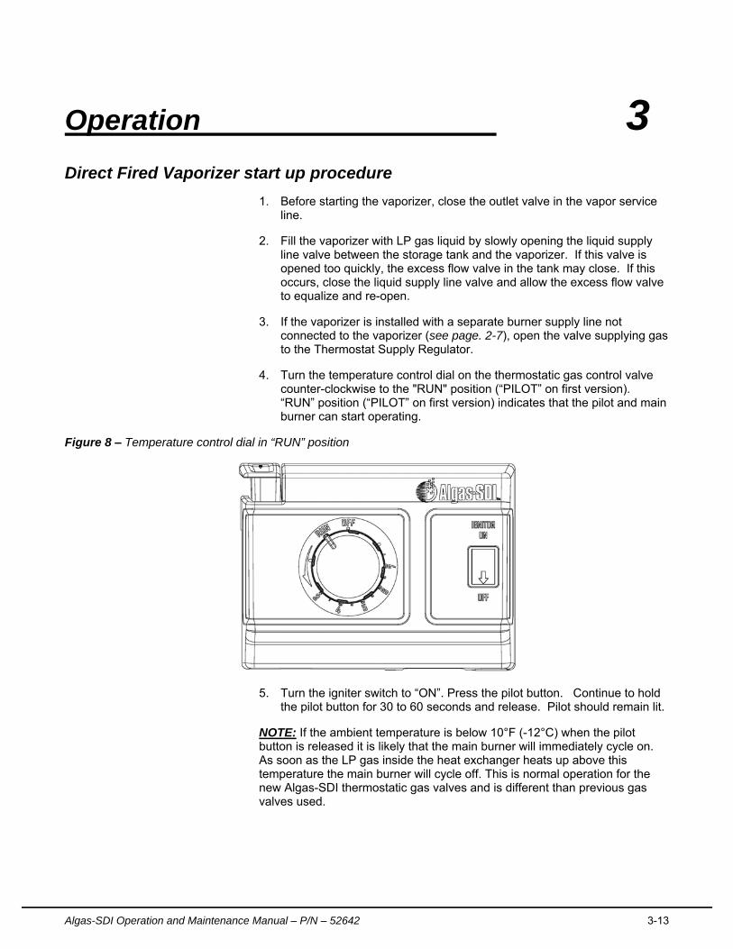
4. Turn the temperature control dial on the thermostatic gas control valve counter-clockwise to the "RUN" position (“PILOT” on first version). “RUN” position (“PILOT” on first version) indicates that the pilot and main burner can start operating.
Figure 8 – Temperature control dial in “RUN” position
5. Turn the igniter switch to “ON”. Press the pilot button. Continue to hold the pilot button for 30 to 60 seconds and release. Pilot should remain lit.
NOTE: If the ambient temperature is below 10°F (-12°C) when the pilot button is released it is likely that the main burner will immediately cycle on. As soon as the LP gas inside the heat exchanger heats up above this temperature the main burner will cycle off. This is normal operation for the new Algas-SDI thermostatic gas valves and is different than previous gas valves used.
Operation
3-14 Algas-SDI Operation and Maintenance Manual – P/N - 52642
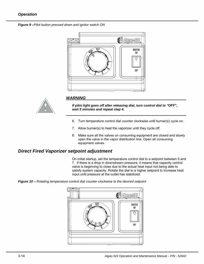
Figure 9 –Pilot button pressed down and ignitor switch ON
WARNING
If pilot light goes off after releasing dial, turn control dial to "OFF", wait 5 minutes and repeat step 4.
6. Turn temperature control dial counter clockwise until burner(s) cycle on.
7. Allow burner(s) to heat the vaporizer until they cycle off.
8. Make sure all the valves on consuming equipment are closed and slowly open the valve in the vapor distribution line. Open all consuming equipment valves.
Direct Fired Vaporizer setpoint adjustment
On initial startup, set the temperature control dial to a setpoint between 5 and 7. If there is a drop in downstream pressure, it means that capacity control valve is beginning to close due to the actual heat input not being able to satisfy system capacity. Rotate the dial to a higher setpoint to increase heat input until pressure at the outlet has stabilized.
Figure 10 – Rotating temperature control dial counter-clockwise to the desired setpoint
Operation
Algas-SDI Operation and Maintenance Manual – P/N – 52642 3-15
Direct Fired Vaporizer shut down procedure
1. Turn temperature control dial to “OFF” position. Pilot flame should immediately extinguish.
2. Once the pilot flame has extinguished turn the ignitor switch to “OFF.
3. If the vaporizer is below -10°F (-12°C) the main burner may continue to operate for an additional 30-40 seconds until thermocouple cools down.
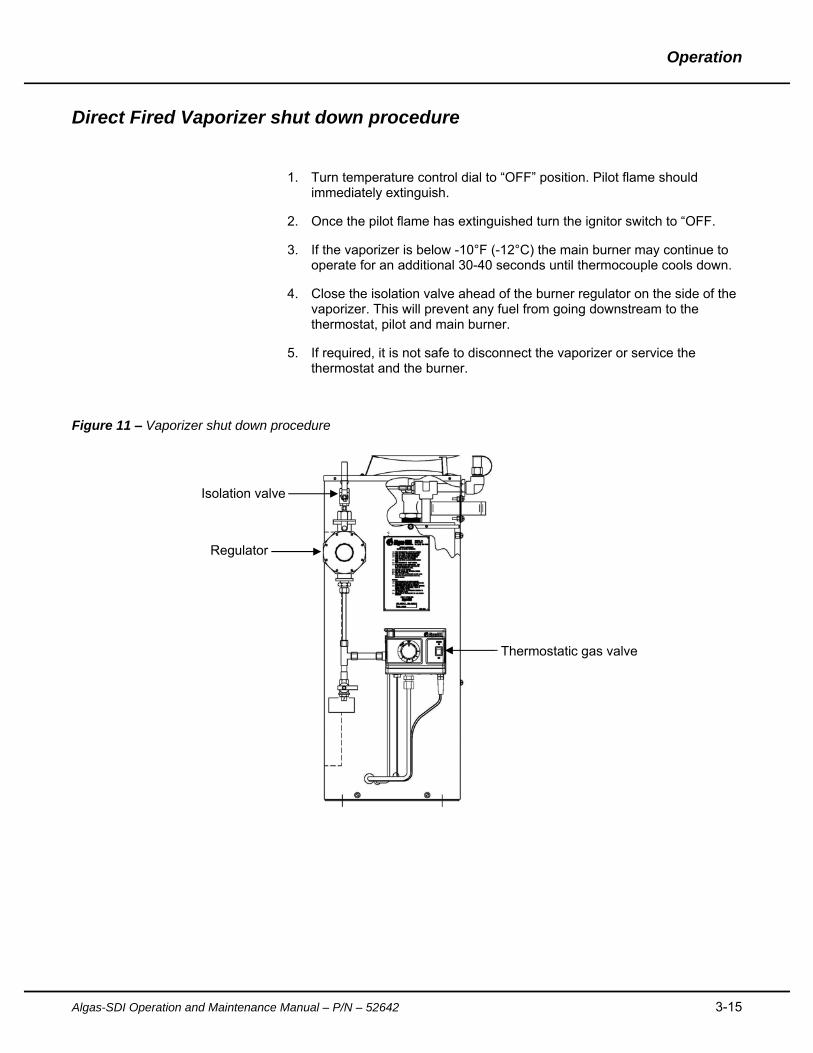
4. Close the isolation valve ahead of the burner regulator on the side of the vaporizer. This will prevent any fuel from going downstream to the thermostat, pilot and main burner.
5. If required, it is not safe to disconnect the vaporizer or service the thermostat and the burner.
Figure 11 – Vaporizer shut down procedure
Isolation valve
Thermostatic gas valve
Regulator
Operation
3-16 Algas-SDI Operation and Maintenance Manual – P/N - 52642
Direct Fired Vaporizer purge procedure
If the vaporizer is not going to be used for a long period of time, it should be purged. The information contained below is a step by step procedure on how to purge Algas-SDI direct fired vaporizer. This procedure should be followed anytime a vaporizer needs to be maintained, serviced, relocated or shut down for any other reason.
WARNING
Prior to purging the vaporizer, ensure that there are no closed ball valves or back check valves restricting the flow of liquid to the tank.
1. Close outlet valve at exit of the vaporizer.
2. If the vaporizer is not operating, start the vaporizer per “Starting the
Vaporizer” procedure.
3. After the burner cycles off, shut down the vaporizer per “Direct Fired vaporizer shut down procedure”.
4. Before proceeding validate that the burner flame, pilot flame, ignitor spark
and any other sources of ignition are completely extinguished.
5. Close the tank liquid outlet valve.
6. Open the vaporizer outlet valve and flare or allow attached equipment to consume remaining gas in the line.
AUTOMATIC RE-IGNITION OPERATION
Lighting or re-lighting of the pilot flame is accomplished by a spark across a gap of approximately 5/32" from the electrode tip to the grounded surface of the pilot burner or to the thermocouple tip. When the flame is established, the pilot flame conducts a current to the grounded pilot burner and a solid state switch in the unit turns off the spark. If the pilot flame is extinguished, current to ground is interrupted and the solid state switch turns on the spark, which sparks at a nominal timing of 100 times per minute, re-lighting the pilot flame well before the thermocouple cools enough to drop out the thermostat safety system.
ECONOMY OPERATION
During normal operation and while the tank pressure is above 30 psig the primary vapor regulator supplies vapor to the load. During this time the economy regulator on the discharge side of the vaporizer remains closed, until the tank pressure drops below 30 psig. Low ambient temperatures may cause this low pressure in the fall or winter or by excessive demand such that the natural vaporization cannot maintain the tank pressure. When the tank pressure drops below 30 psig, the economy regulator opens allowing flow through the vaporizer and subsequently the higher discharge pressure from the vaporizer regulator (3) overcomes the lower setting of the primary vapor regulator. This allows flow only through the vaporizer thus preventing the tank pressure from being drawn down.

Operation
Algas-SDI Operation and Maintenance Manual – P/N – 52642 3-17
This page left intentionally blank
4-18 Algas-SDI Operation and Maintenance Manual – P/N – 52642
Maintenance 4 Maintenance Recommendations
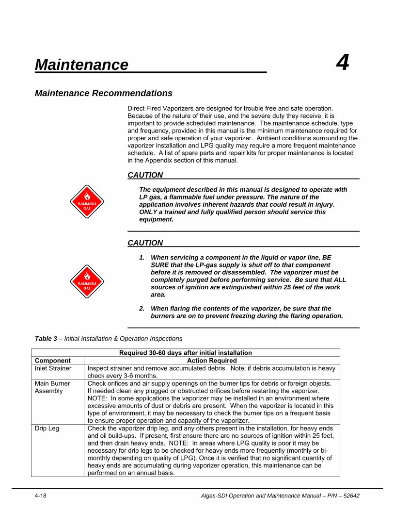
Direct Fired Vaporizers are designed for trouble free and safe operation. Because of the nature of their use, and the severe duty they receive, it is important to provide scheduled maintenance. The maintenance schedule, type and frequency, provided in this manual is the minimum maintenance required for proper and safe operation of your vaporizer. Ambient conditions surrounding the vaporizer installation and LPG quality may require a more frequent maintenance schedule. A list of spare parts and repair kits for proper maintenance is located in the Appendix section of this manual.
CAUTION
The equipment described in this manual is designed to operate with LP gas, a flammable fuel under pressure. The nature of the application involves inherent hazards that could result in injury. ONLY a trained and fully qualified person should service this equipment.
CAUTION
1. When servicing a component in the liquid or vapor line, BE SURE that the LP-gas supply is shut off to that component before it is removed or disassembled. The vaporizer must be completely purged before performing service. Be sure that ALL sources of ignition are extinguished within 25 feet of the work area.
2. When flaring the contents of the vaporizer, be sure that the burners are on to prevent freezing during the flaring operation.
Table 3 – Initial Installation & Operation Inspections
Required 30-60 days after initial installation Component Action Required Inlet Strainer Inspect strainer and remove accumulated debris. Note; if debris accumulation is heavy
check every 3-6 months. Main Burner Assembly
Check orifices and air supply openings on the burner tips for debris or foreign objects. If needed clean any plugged or obstructed orifices before restarting the vaporizer. NOTE: In some applications the vaporizer may be installed in an environment where excessive amounts of dust or debris are present. When the vaporizer is located in this type of environment, it may be necessary to check the burner tips on a frequent basis to ensure proper operation and capacity of the vaporizer.
Drip Leg Check the vaporizer drip leg, and any others present in the installation, for heavy ends and oil build-ups. If present, first ensure there are no sources of ignition within 25 feet, and then drain heavy ends. NOTE: In areas where LPG quality is poor it may be necessary for drip legs to be checked for heavy ends more frequently (monthly or bi-monthly depending on quality of LPG). Once it is verified that no significant quantity of heavy ends are accumulating during vaporizer operation, this maintenance can be performed on an annual basis.
Maintenance
Algas-SDI Operation and Maintenance Manual – P/N – 52642 4-19
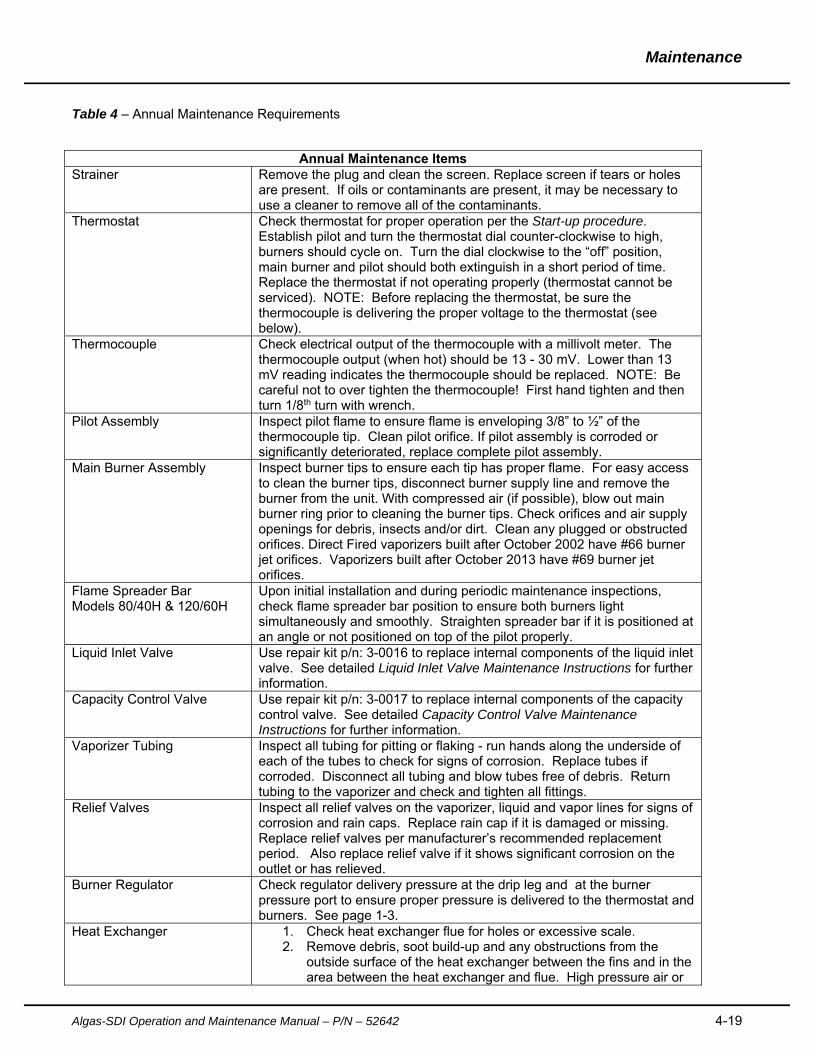
Table 4 – Annual Maintenance Requirements
Annual Maintenance Items Strainer Remove the plug and clean the screen. Replace screen if tears or holes
are present. If oils or contaminants are present, it may be necessary to use a cleaner to remove all of the contaminants.
Thermostat Check thermostat for proper operation per the Start-up procedure. Establish pilot and turn the thermostat dial counter-clockwise to high, burners should cycle on. Turn the dial clockwise to the “off” position, main burner and pilot should both extinguish in a short period of time. Replace the thermostat if not operating properly (thermostat cannot be serviced). NOTE: Before replacing the thermostat, be sure the thermocouple is delivering the proper voltage to the thermostat (see below).
Thermocouple Check electrical output of the thermocouple with a millivolt meter. The thermocouple output (when hot) should be 13 - 30 mV. Lower than 13 mV reading indicates the thermocouple should be replaced. NOTE: Be careful not to over tighten the thermocouple! First hand tighten and then turn 1/8th turn with wrench.
Pilot Assembly Inspect pilot flame to ensure flame is enveloping 3/8” to ½” of the thermocouple tip. Clean pilot orifice. If pilot assembly is corroded or significantly deteriorated, replace complete pilot assembly.
Main Burner Assembly Inspect burner tips to ensure each tip has proper flame. For easy access to clean the burner tips, disconnect burner supply line and remove the burner from the unit. With compressed air (if possible), blow out main burner ring prior to cleaning the burner tips. Check orifices and air supply openings for debris, insects and/or dirt. Clean any plugged or obstructed orifices. Direct Fired vaporizers built after October 2002 have #66 burner jet orifices. Vaporizers built after October 2013 have #69 burner jet orifices.
Flame Spreader Bar Models 80/40H & 120/60H
Upon initial installation and during periodic maintenance inspections, check flame spreader bar position to ensure both burners light simultaneously and smoothly. Straighten spreader bar if it is positioned at an angle or not positioned on top of the pilot properly.
Liquid Inlet Valve Use repair kit p/n: 3-0016 to replace internal components of the liquid inlet valve. See detailed Liquid Inlet Valve Maintenance Instructions for further information.
Capacity Control Valve Use repair kit p/n: 3-0017 to replace internal components of the capacity control valve. See detailed Capacity Control Valve Maintenance Instructions for further information.
Vaporizer Tubing Inspect all tubing for pitting or flaking - run hands along the underside of each of the tubes to check for signs of corrosion. Replace tubes if corroded. Disconnect all tubing and blow tubes free of debris. Return tubing to the vaporizer and check and tighten all fittings.
Relief Valves Inspect all relief valves on the vaporizer, liquid and vapor lines for signs of corrosion and rain caps. Replace rain cap if it is damaged or missing. Replace relief valves per manufacturer’s recommended replacement period. Also replace relief valve if it shows significant corrosion on the outlet or has relieved.
Burner Regulator Check regulator delivery pressure at the drip leg and at the burner pressure port to ensure proper pressure is delivered to the thermostat and burners. See page 1-3.
Heat Exchanger 1. Check heat exchanger flue for holes or excessive scale. 2. Remove debris, soot build-up and any obstructions from the
outside surface of the heat exchanger between the fins and in the area between the heat exchanger and flue. High pressure air or
Maintenance
4-20 Algas-SDI Operation and Maintenance Manual – P/N - 52642
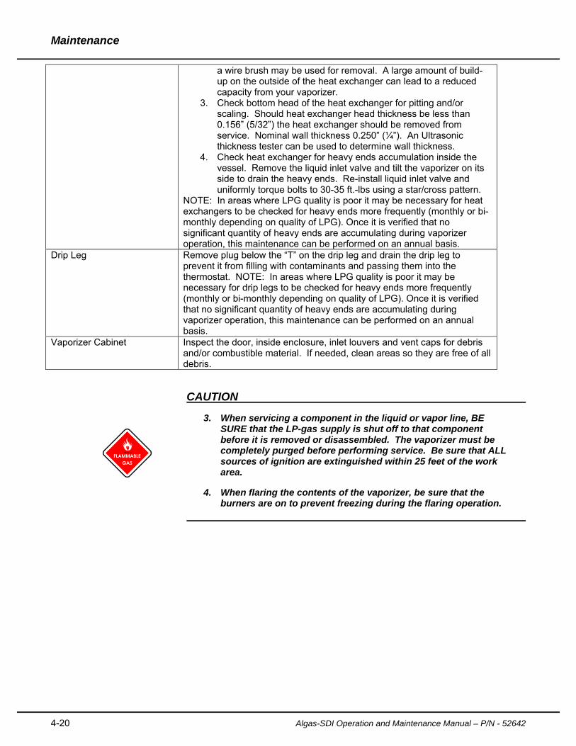
a wire brush may be used for removal. A large amount of build-up on the outside of the heat exchanger can lead to a reduced capacity from your vaporizer.
3. Check bottom head of the heat exchanger for pitting and/or scaling. Should heat exchanger head thickness be less than 0.156” (5/32”) the heat exchanger should be removed from service. Nominal wall thickness 0.250” (¼”). An Ultrasonic thickness tester can be used to determine wall thickness.
4. Check heat exchanger for heavy ends accumulation inside the vessel. Remove the liquid inlet valve and tilt the vaporizer on its side to drain the heavy ends. Re-install liquid inlet valve and uniformly torque bolts to 30-35 ft.-lbs using a star/cross pattern.
NOTE: In areas where LPG quality is poor it may be necessary for heat exchangers to be checked for heavy ends more frequently (monthly or bi-monthly depending on quality of LPG). Once it is verified that no significant quantity of heavy ends are accumulating during vaporizer operation, this maintenance can be performed on an annual basis.
Drip Leg Remove plug below the “T” on the drip leg and drain the drip leg to prevent it from filling with contaminants and passing them into the thermostat. NOTE: In areas where LPG quality is poor it may be necessary for drip legs to be checked for heavy ends more frequently (monthly or bi-monthly depending on quality of LPG). Once it is verified that no significant quantity of heavy ends are accumulating during vaporizer operation, this maintenance can be performed on an annual basis.
Vaporizer Cabinet Inspect the door, inside enclosure, inlet louvers and vent caps for debris and/or combustible material. If needed, clean areas so they are free of all debris.
CAUTION
3. When servicing a component in the liquid or vapor line, BE SURE that the LP-gas supply is shut off to that component before it is removed or disassembled. The vaporizer must be completely purged before performing service. Be sure that ALL sources of ignition are extinguished within 25 feet of the work area.
4. When flaring the contents of the vaporizer, be sure that the burners are on to prevent freezing during the flaring operation.
Maintenance
Algas-SDI Operation and Maintenance Manual – P/N – 52642 4-21
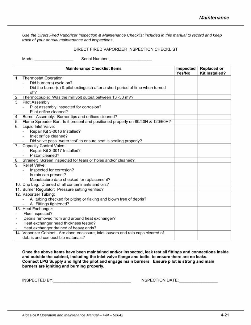
Use the Direct Fired Vaporizer Inspection & Maintenance Checklist included in this manual to record and keep track of your annual maintenance and inspections.
DIRECT FIRED VAPORIZER INSPECTION CHECKLIST
Model:_________________ Serial Number:___________________
Maintenance Checklist Items Inspected Yes/No
Replaced or Kit Installed?
1. Thermostat Operation: ‐ Did burner(s) cycle on? ‐ Did the burner(s) & pilot extinguish after a short period of time when turned
off?
2. Thermocouple: Was the millivolt output between 13 -30 mV? 3. Pilot Assembly:
‐ Pilot assembly inspected for corrosion? ‐ Pilot orifice cleaned?
4. Burner Assembly: Burner tips and orifices cleaned? 5. Flame Spreader Bar: Is it present and positioned properly on 80/40H & 120/60H? 6. Liquid Inlet Valve:
‐ Repair Kit 3-0016 Installed? ‐ Inlet orifice cleaned? ‐ Did valve pass “water test” to ensure seat is sealing properly?
7. Capacity Control Valve: ‐ Repair Kit 3-0017 Installed? ‐ Piston cleaned?
8. Strainer: Screen inspected for tears or holes and/or cleaned? 9. Relief Valve:
‐ Inspected for corrosion? ‐ Is rain cap present? ‐ Manufacture date checked for replacement?
10. Drip Leg: Drained of all contaminants and oils? 11. Burner Regulator: Pressure setting verified? 12. Vaporizer Tubing:
‐ All tubing checked for pitting or flaking and blown free of debris? ‐ All Fittings tightened?
13. Heat Exchanger: ‐ Flue inspected? ‐ Debris removed from and around heat exchanger? ‐ Heat exchanger head thickness tested? ‐ Heat exchanger drained of heavy ends?
14. Vaporizer Cabinet: Are door, enclosure, inlet louvers and rain caps cleared of debris and combustible materials?
Once the above items have been maintained and/or inspected, leak test all fittings and connections inside and outside the cabinet, including the inlet valve flange and bolts, to ensure there are no leaks. Connect LPG Supply and light the pilot and engage main burners. Ensure pilot is strong and main burners are igniting and burning properly. INSPECTED BY:__________________________________ INSPECTION DATE:_________________
Maintenance
4-22 Algas-SDI Operation and Maintenance Manual – P/N - 52642
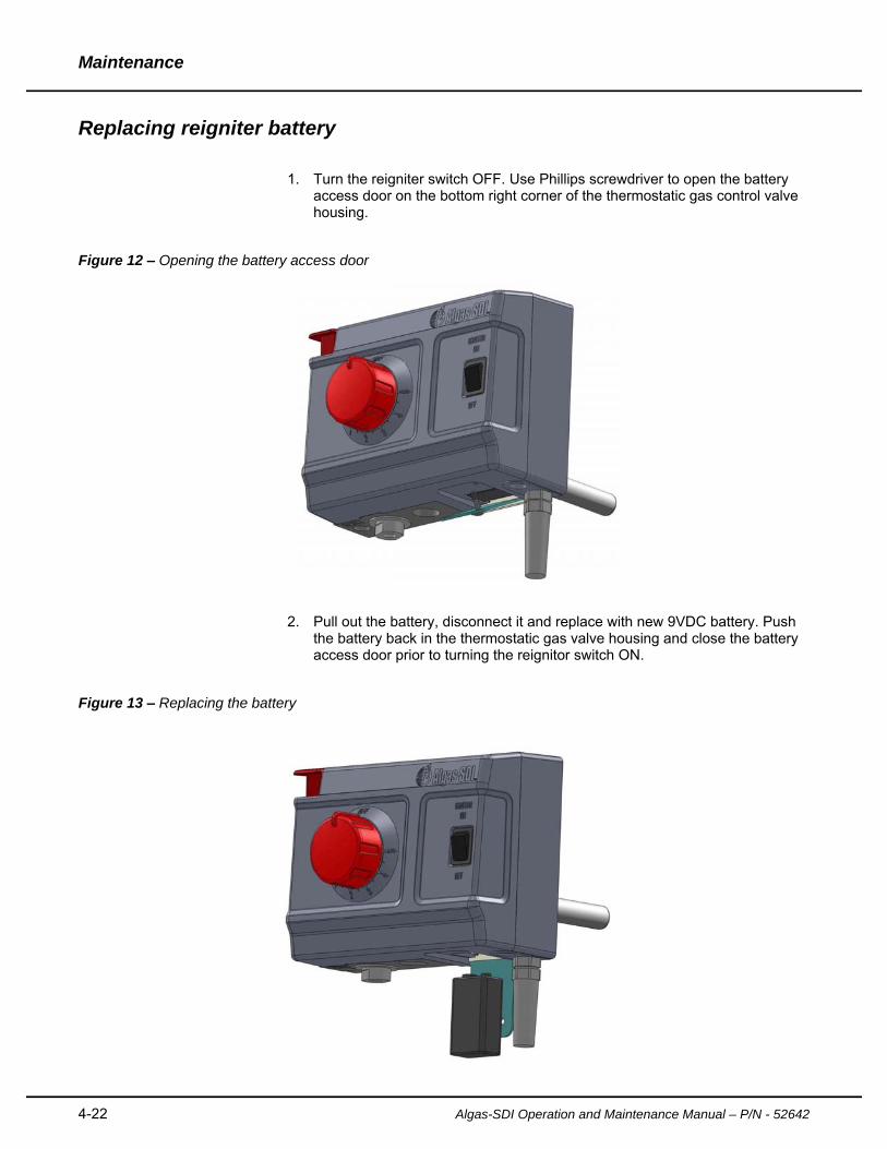
Replacing reigniter battery
1. Turn the reigniter switch OFF. Use Phillips screwdriver to open the battery
access door on the bottom right corner of the thermostatic gas control valve housing.
Figure 12 – Opening the battery access door
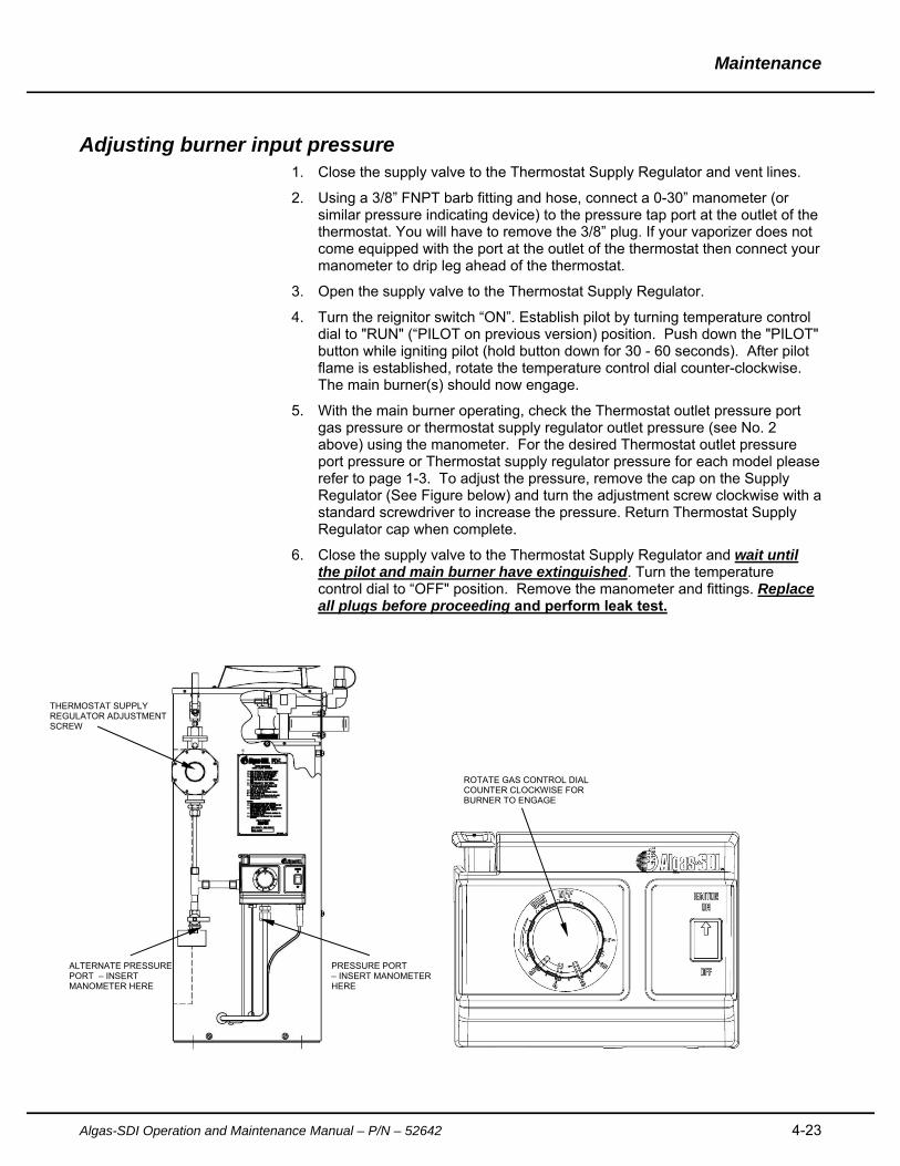
2. Pull out the battery, disconnect it and replace with new 9VDC battery. Push
the battery back in the thermostatic gas valve housing and close the battery access door prior to turning the reignitor switch ON.
Figure 13 – Replacing the battery
Maintenance
Algas-SDI Operation and Maintenance Manual – P/N – 52642 4-23
Adjusting burner input pressure 1. Close the supply valve to the Thermostat Supply Regulator and vent lines.
2. Using a 3/8” FNPT barb fitting and hose, connect a 0-30” manometer (or similar pressure indicating device) to the pressure tap port at the outlet of the thermostat. You will have to remove the 3/8” plug. If your vaporizer does not come equipped with the port at the outlet of the thermostat then connect your manometer to drip leg ahead of the thermostat.
3. Open the supply valve to the Thermostat Supply Regulator.
4. Turn the reignitor switch “ON”. Establish pilot by turning temperature control dial to "RUN" (“PILOT on previous version) position. Push down the "PILOT" button while igniting pilot (hold button down for 30 - 60 seconds). After pilot flame is established, rotate the temperature control dial counter-clockwise. The main burner(s) should now engage.
5. With the main burner operating, check the Thermostat outlet pressure port gas pressure or thermostat supply regulator outlet pressure (see No. 2 above) using the manometer. For the desired Thermostat outlet pressure port pressure or Thermostat supply regulator pressure for each model please refer to page 1-3. To adjust the pressure, remove the cap on the Supply Regulator (See Figure below) and turn the adjustment screw clockwise with a standard screwdriver to increase the pressure. Return Thermostat Supply Regulator cap when complete.
6. Close the supply valve to the Thermostat Supply Regulator and wait until the pilot and main burner have extinguished. Turn the temperature control dial to “OFF" position. Remove the manometer and fittings. Replace all plugs before proceeding and perform leak test.
THERMOSTAT SUPPLY REGULATOR ADJUSTMENT SCREW
PRESSURE PORT – INSERT MANOMETER HERE
ROTATE GAS CONTROL DIAL COUNTER CLOCKWISE FOR BURNER TO ENGAGE
ALTERNATE PRESSURE PORT – INSERT MANOMETER HERE
Maintenance
4-24 Algas-SDI Operation and Maintenance Manual – P/N - 52642
Liquid inlet valve maintenance procedure Use Repair Kit P/n: 3-0016 (see repair kit section for kit details)
NOTE: Vaporizer must be purged and empty of all liquid and vapor prior to performing maintenance on the liquid inlet valve.
1. Loosen the four bolts to remove liquid inlet valve cover on the outside of the vaporizer cabinet.
2. Using a 7/16” end wrench or tubing wrench, loosen and remove the capacity control valve sensing line fitting on the top of the inlet valve.
3. With a 1-1/2” box end wrench (suggest using 6 point), loosen the large nut on
the top of the inlet valve (inlet valve cap)
4. Loosen the 6 inlet valve flange bolts and remove the inlet valve from the vaporizer through the hole in the cabinet.
5. Once the valve is removed from the vaporizer, remove the inlet valve cap
(large nut on top) and remove the spring from the valve.
6. Remove the valve seat and stem from the valve body and orifice.
7. After the seat and stem have been removed, using a socket, remove the inlet valve orifice and wipe the top of the inlet valve orifice with a rag/cloth (one that does not leave lint on surface) or lightly with a scotch-brite type material to remove any debris and/or oils from the orifice surface.
8. Replace the O-ring under the orifice (use smallest O-ring from kit). Lightly
grease new O-ring before replacing it.
9. Once the inlet valve orifice O-ring has been replaced, return the orifice to the valve and tighten accordingly.
10. Compare the length of the new stem from the repair kit to the old one that
was removed from the vaporizer to make sure they are the same. It is important to make sure the new valve stem isn’t longer than the original stem because it might prevent the valve from sealing properly. If needed, use a metal file to shorten the stem to match the original stem length. New vaporizers are fitted correctly and tested at the factory to make sure the seat and stem assemblies have the proper length. If the seat and stem assemblies have been changed in the field without checking the length against the original stem or the valve was not tested in the shop to ensure it is sealing (see “Water test” procedure below) there is a chance the stem could be too long and not allow the inlet valve to close properly. If you are uncertain about the prior replacement history of the valve stem you should ensure the valve is tested in water to make sure the new stem and seat assembly close fully before returning the inlet valve to the vaporizer.
11. Insert the new valve seat and stem assembly into the valve body lining up
the stem with the hole in the inlet orifice.
12. Replace the spring making sure it is centered on the top of the inlet valve seat.
Maintenance
Algas-SDI Operation and Maintenance Manual – P/N – 52642 4-25
13. Lightly grease and replace the O-ring around the inlet valve cap (large flange
nut). 14. Install inlet valve cap (large flange nut) and tighten into valve body. You may
apply NEVER-SEEZ compound to the flange nut to allow for easy removal of the flange nut in the future.
15. Once the internal components of the valve are replaced perform a “water
test” to ensure your inlet valve is sealing properly. To perform this test: apply a 1/8” plug in the top of the inlet valve cap using Teflon tape to ensure it is leak-proof. Using an air hose, apply 80-100 psi of air pressure at the inlet of the valve and completely submerge the valve in a bucket or sink full of water. Wait approximately 5-10 seconds and observe for air bubbles exiting the valve around valve stem that protrudes from the middle of the inlet valve. If not bubbles are present, the valve is sealing properly.
16. Remove any remnants of the old inlet valve flange gasket from the surface of
the flange on the inlet valve itself and on the flange at the heat exchanger.
17. Lightly spray new inlet valve flange gasket with a dry lubricant (graphite) before installing it on the unit.
18. When re-installing the inlet valve on the vaporizer, place flange gasket on the
gasket surface and slide the stem under the float ball inside the heat exchanger. Slightly tighten the bottom two flange bolts allowing the flange gasket to be supported by the two bottom bolts. Working your way around the valve, hand tighten the remainder of the bolts inspecting as you tighten them to ensure the position of the inlet valve flange gasket is correct.
19. To tighten the inlet valve bolts, torque the 6 bolts to 30-35 ft.-lbs. in a
cross/star pattern.
20. Leak test inlet valve flange bolts prior to re-starting the vaporizer.
Maintenance
4-26 Algas-SDI Operation and Maintenance Manual – P/N - 52642
Capacity control valve maintenance procedure
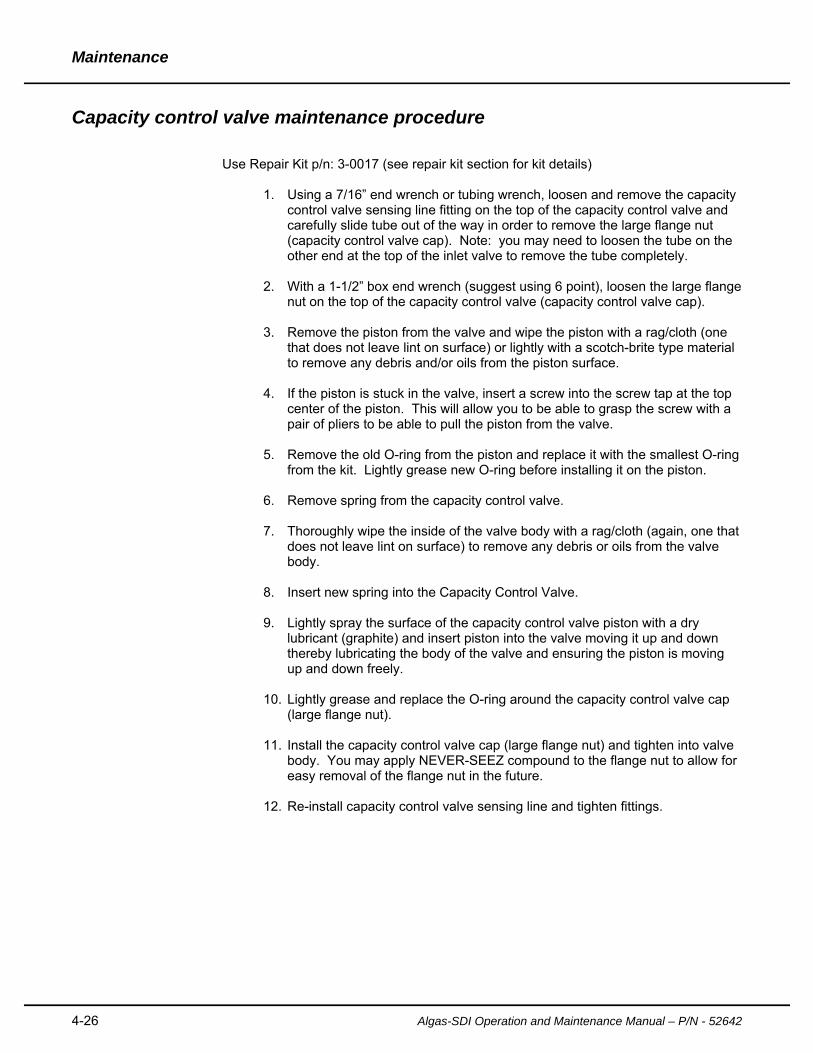
Use Repair Kit p/n: 3-0017 (see repair kit section for kit details)
1. Using a 7/16” end wrench or tubing wrench, loosen and remove the capacity
control valve sensing line fitting on the top of the capacity control valve and carefully slide tube out of the way in order to remove the large flange nut (capacity control valve cap). Note: you may need to loosen the tube on the other end at the top of the inlet valve to remove the tube completely.
2. With a 1-1/2” box end wrench (suggest using 6 point), loosen the large flange nut on the top of the capacity control valve (capacity control valve cap).
3. Remove the piston from the valve and wipe the piston with a rag/cloth (one
that does not leave lint on surface) or lightly with a scotch-brite type material to remove any debris and/or oils from the piston surface.
4. If the piston is stuck in the valve, insert a screw into the screw tap at the top
center of the piston. This will allow you to be able to grasp the screw with a pair of pliers to be able to pull the piston from the valve.
5. Remove the old O-ring from the piston and replace it with the smallest O-ring
from the kit. Lightly grease new O-ring before installing it on the piston.
6. Remove spring from the capacity control valve.
7. Thoroughly wipe the inside of the valve body with a rag/cloth (again, one that does not leave lint on surface) to remove any debris or oils from the valve body.
8. Insert new spring into the Capacity Control Valve.
9. Lightly spray the surface of the capacity control valve piston with a dry
lubricant (graphite) and insert piston into the valve moving it up and down thereby lubricating the body of the valve and ensuring the piston is moving up and down freely.
10. Lightly grease and replace the O-ring around the capacity control valve cap
(large flange nut).
11. Install the capacity control valve cap (large flange nut) and tighten into valve body. You may apply NEVER-SEEZ compound to the flange nut to allow for easy removal of the flange nut in the future.
12. Re-install capacity control valve sensing line and tighten fittings.

Maintenance
Algas-SDI Operation and Maintenance Manual – P/N – 52642 4-27
This page intentionally left blank.
5-28 Algas-SDI Operation and Maintenance Manual – P/N – 52642
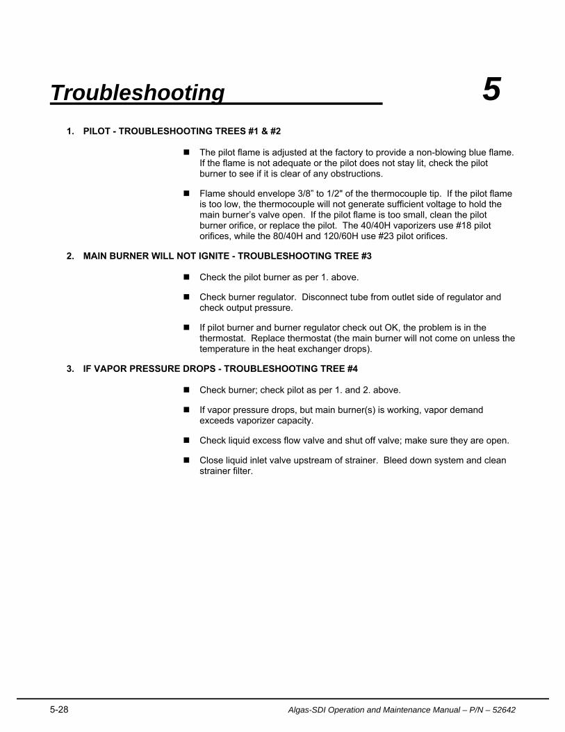
Troubleshooting 5 1. PILOT - TROUBLESHOOTING TREES #1 & #2
The pilot flame is adjusted at the factory to provide a non-blowing blue flame.
If the flame is not adequate or the pilot does not stay lit, check the pilot burner to see if it is clear of any obstructions.
Flame should envelope 3/8” to 1/2" of the thermocouple tip. If the pilot flame is too low, the thermocouple will not generate sufficient voltage to hold the main burner’s valve open. If the pilot flame is too small, clean the pilot burner orifice, or replace the pilot. The 40/40H vaporizers use #18 pilot orifices, while the 80/40H and 120/60H use #23 pilot orifices.
2. MAIN BURNER WILL NOT IGNITE - TROUBLESHOOTING TREE #3
Check the pilot burner as per 1. above.
Check burner regulator. Disconnect tube from outlet side of regulator and check output pressure.
If pilot burner and burner regulator check out OK, the problem is in the thermostat. Replace thermostat (the main burner will not come on unless the temperature in the heat exchanger drops).
3. IF VAPOR PRESSURE DROPS - TROUBLESHOOTING TREE #4
Check burner; check pilot as per 1. and 2. above.
If vapor pressure drops, but main burner(s) is working, vapor demand exceeds vaporizer capacity.
Check liquid excess flow valve and shut off valve; make sure they are open.
Close liquid inlet valve upstream of strainer. Bleed down system and clean strainer filter.
Troubleshooting
Algas-SDI Operation and Maintenance Manual – P/N – 52642 5-29
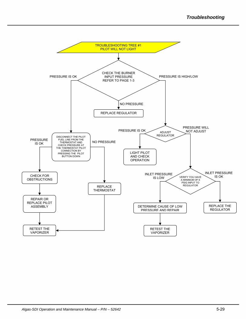
TROUBLESHOOTING TREE #1 PILOT WILL NOT LIGHT
CHECK THE BURNER INPUT PRESSURE
REFER TO PAGE 1-3
DISCONNECT THE PILOT FUEL LINE FROM THE
THERMOSTAT AND CHECK PRESSURE AT
THE THERMOSTAT PILOT CONNECTION BY
PRESSING THE PILOT BUTTON DOWN
PRESSURE IS OK PRESSURE IS HIGH/LOW
ADJUST REGULATOR
VERIFY YOU HAVE A MINIMUM OF 6 PSIG INPUT TO
REGULATOR
DETERMINE CAUSE OF LOW PRESSURE AND REPAIR
NO PRESSURE
REPLACE REGULATOR
PRESSURE IS OK
LIGHT PILOT AND CHECK OPERATION
PRESSURE WILL NOT ADJUST
INLET PRESSURE IS LOW
REPLACE THE REGULATOR
RETEST THE VAPORIZER
INLET PRESSURE IS OK
REPAIR OR REPLACE PILOT
ASSEMBLY
CHECK FOR OBSTRUCTIONS
REPLACE THERMOSTAT
RETEST THE VAPORIZER
PRESSURE IS OK NO PRESSURE
Troubleshooting
5-30 Algas-SDI Operation and Maintenance Manual – P/N - 52642
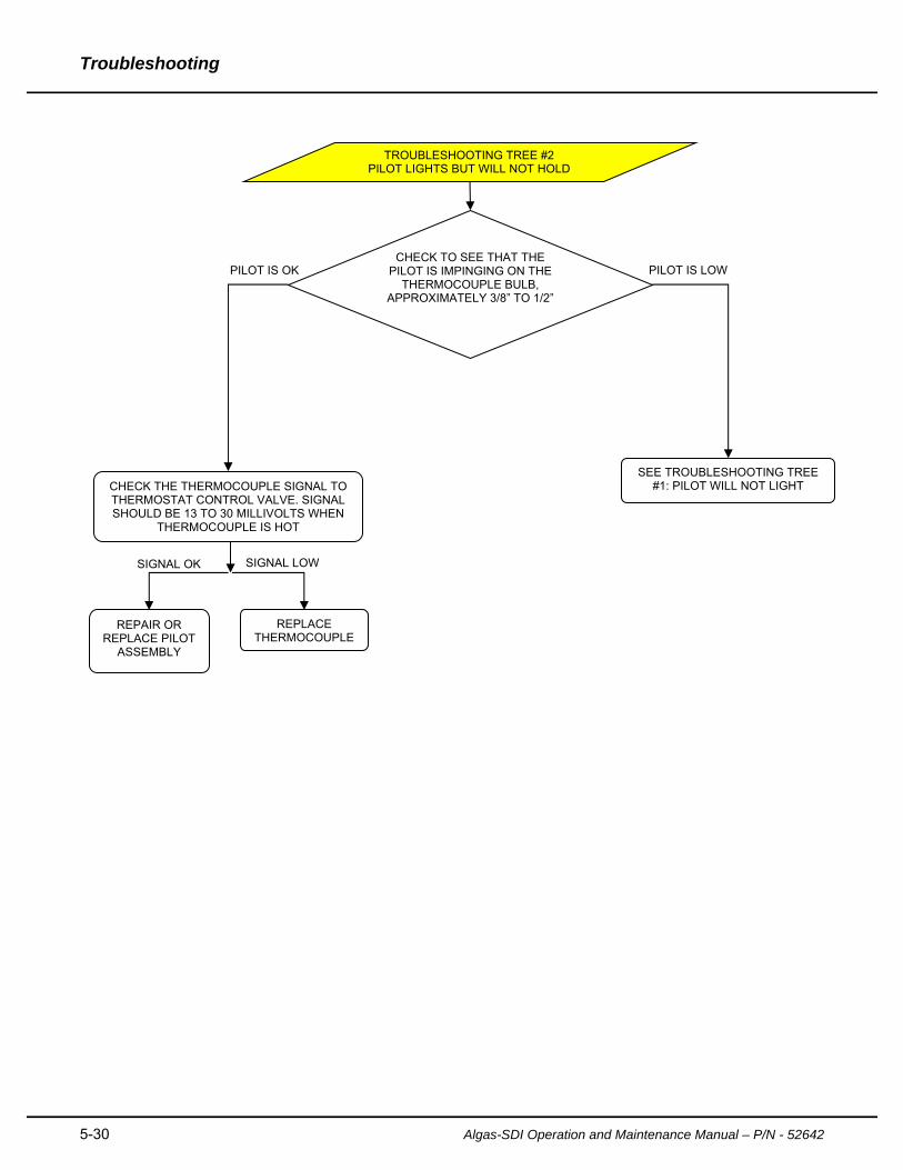
TROUBLESHOOTING TREE #2 PILOT LIGHTS BUT WILL NOT HOLD
CHECK TO SEE THAT THE PILOT IS IMPINGING ON THE
THERMOCOUPLE BULB, APPROXIMATELY 3/8” TO 1/2”
CHECK THE THERMOCOUPLE SIGNAL TO THERMOSTAT CONTROL VALVE. SIGNAL SHOULD BE 13 TO 30 MILLIVOLTS WHEN
THERMOCOUPLE IS HOT
REPAIR OR REPLACE PILOT
ASSEMBLY
PILOT IS OK PILOT IS LOW
SEE TROUBLESHOOTING TREE #1: PILOT WILL NOT LIGHT
REPLACE THERMOCOUPLE
SIGNAL OK SIGNAL LOW

Troubleshooting
Algas-SDI Operation and Maintenance Manual – P/N – 52642 5-31
TROUBLESHOOTING TREE #3 MAIN BURNER WILL NOT LIGHT
CHECK TO SEE THAT THE PILOT IS IMPINGING ON THE
THERMOCOUPLE BULB, APPROXIMATELY 3/8” TO 1/2”
TURN THE THERMOSTATIC GAS VALVE TEMPERATURE CONTROL DIAL UP TO
THE HIGHEST SETTING. DID THE CONTROL “CLICK”?
CHECK FOR PLUGGED GAS
LINE TO THE BURNER
NO YES
SEE TROUBLESHOOTING TREE #1 OR #2
REPLACE THERMOSTAT
YES NO
Troubleshooting
5-32 Algas-SDI Operation and Maintenance Manual – P/N - 52642
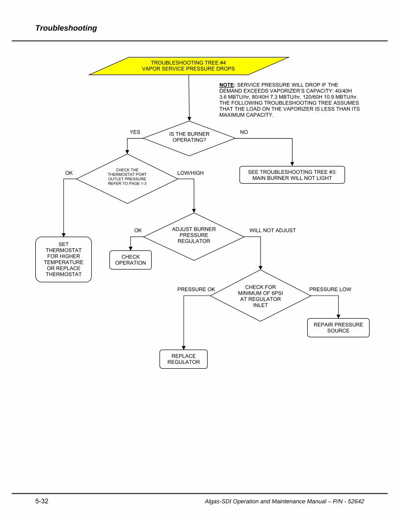
TROUBLESHOOTING TREE #4 VAPOR SERVICE PRESSURE DROPS
IS THE BURNER OPERATING?
CHECK OPERATION
YES
NOTE: SERVICE PRESSURE WILL DROP IF THE DEMAND EXCEEDS VAPORIZER’S CAPACITY: 40/40H 3.6 MBTU/hr, 80/40H 7.3 MBTU/hr, 120/60H 10.9 MBTU/hr. THE FOLLOWING TROUBLESHOOTING TREE ASSUMES THAT THE LOAD ON THE VAPORIZER IS LESS THAN ITS MAXIMUM CAPACITY.
NO
ADJUST BURNER PRESSURE
REGULATOR
OK
SEE TROUBLESHOOTING TREE #3: MAIN BURNER WILL NOT LIGHT
WILL NOT ADJUST
CHECK FOR MINIMUM OF 6PSI AT REGULATOR
INLET
REPLACE REGULATOR
REPAIR PRESSURE SOURCE
PRESSURE LOW PRESSURE OK
CHECK THE THERMOSTAT PORT OUTLET PRESSURE REFER TO PAGE 1-3
SET THERMOSTAT FOR HIGHER
TEMPERATURE OR REPLACE THERMOSTAT
OK LOW/HIGH

Troubleshooting
Algas-SDI Operation and Maintenance Manual – P/N – 52642 5-33
This page intentionally left blank.
A-34 Algas-SDI Operation and Maintenance Manual – P/N – 52642
APPENDIX A
TECHNICAL INFORMATION

Appendix A
Algas-SDI Operation and Maintenance Manual – P/N – 52642 A-35
This page intentionally left blank.
Appendix A
A-36 Algas-SDI Operation and Maintenance Manual – P/N - 52642
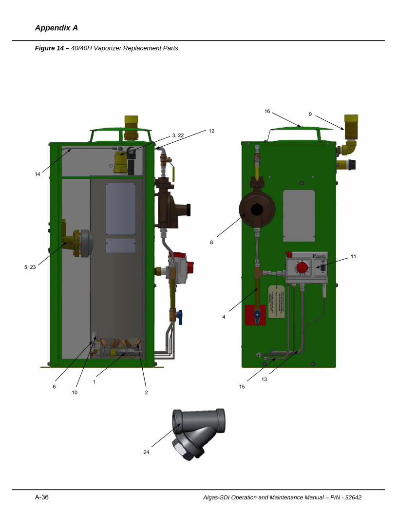
Figure 14 – 40/40H Vaporizer Replacement Parts
1
2
3, 22
4
5, 23
6 10
8
9
11
12
13
14
15
16
24
Appendix A
Algas-SDI Operation and Maintenance Manual – P/N – 52642 A-37
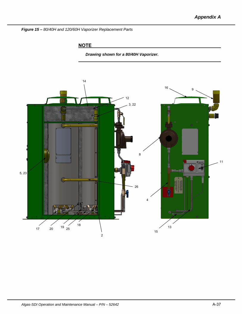
Figure 15 – 80/40H and 120/60H Vaporizer Replacement Parts
NOTE
Drawing shown for a 80/40H Vaporizer.
17 18
19 20 25
26
9 16
4
8
11
13
152
5, 23
12
3, 22
14
Appendix A
A-38 Algas-SDI Operation and Maintenance Manual – P/N - 52642
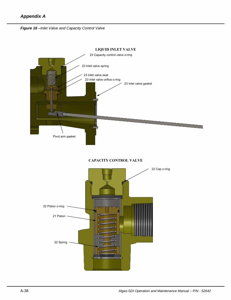
Figure 16 –Inlet Valve and Capacity Control Valve
LIQUID INLET VALVE
CAPACITY CONTROL VALVE
21 Piston
23 Inlet valve gasket
23 Inlet valve seat
23 Inlet valve spring
23 Capacity control valve o-ring
23 Inlet valve orifice o-ring
Pivot arm gasket
22 Piston o-ring
22 Cap o-ring
22 Spring
Appendix A
Algas-SDI Operation and Maintenance Manual – P/N – 52642 A-39
Figure 14, 15 and 16 Descriptions
1. Burner Manifold 40/40H, 60/60H new burner post 10/02 P/N: 1502-4006
2. Burner tip all models – New burner post 10/02 P/N: 33581
3. Capacity control valve 1” – All models P/N: 1508-4001
4. Drip leg kit 40/40H, 60/60H, 80/40H, 120/60H P/N: 40403
5. Liquid inlet valve – All models P/N: 1501-4001
6. Pilot assembly kit 40/40H, 60/60H, snap in style w/ignitor P/N: 42008
7. Pilot flame Guide 40/40H, 60/60H P/N: 1502-5010
8. Regulator, Burner Supply All Models P/N: 34800
9. Relief valve, ¾”NPT UL/CE/ASME w/Cap 250psig (Rego) P/N: 34876
10. Thermocouple 40/40H & 80/40H P/N: 46-4
Thermocouple 120/60H P/N: 37050
11. Thermostat/Thermowell w/9VDC ignitor 40/40H-120/60H P/N: 41073
12. Tube, burner regulator supply Kit 40/40H-120/60H P/N: 40542
13. Tube, burner supply kit 40/40H-120/60H P/N: 42012
14. Tube, capacity control kit 40/40H-120/60H P/N: 42013
15. Tube, pilot supply kit 40/40H-120/60H P/N: 42014
16. Vent cap assembly, removable – convex style P/N: 1501-4015
17. Burner manifold left 80/40H, 120/60H - new bnr. post 10/02 P/N: 1504-4004
18. Burner manifold right 80/40H, 120/60H - new bnr. post 10/02 P/N: 1504-4005
19. Pilot assembly kit 80/40H-120/60H – new bnr. post 10/02 P/N: 41021
20. Pilot flame guide 80/40H,120/60H – new bnr. post 10/02 P/N: 1501-5086
21. Piston, Capacity control valve 1” outlet P/N: 1508-5005
22. Repair kit, Capacity control valve all models P/N: 3-0017
*See Capacity Control valve in Figure 15
23. Repair kit, Liquid Inlet valve all models P/N: 3-0016
*See Liquid Inlet valve in Figure 15
24. Strainer, ¾” NPT P/N: 30655
25. Tube, burner manifold connector kit 80/40H, 120/60H P/N: 3-0783
26. Tube, heat exchanger connector 80/40H, 120/60H P/N: 3-0792

Appendix A
A-40 Algas-SDI Operation and Maintenance Manual – P/N - 52642
Table 5 – Repair Kits and Other Available Replacement Parts
81111: Master rebuild kit 40/40H (#66 orifice)
Part number Description
3-0034 40/40H Master repair kit (new burner)
33581 Burner tip #66 orifice
34800 Pressure reducing valve ¼” inlet x ½” outlet, twin stage
40631: Master rebuild kit 40/40H (#69 orifice)
Part number Description
3-0034 40/40H Master repair kit (new burner)
34323 Burner tip #69 orifice
34800 Pressure reducing valve ¼” inlet x ½” outlet, twin stage
41032: Master rebuild kit 60/60H (#66 orifice)
Part number Description
41030 Kit, 60/60H repair
33581 Burner tip #66 orifice
34800 Pressure reducing valve ¼” inlet x ½” outlet, twin stage
40632: Master rebuild kit 60/60H (#69 orifice)
Part number Description 41030 Kit, 60/60H repair
34323 Burner tip #69 orifice
34800 Pressure reducing valve ¼” inlet x ½” outlet, twin stage
81112: Master rebuild kit 80/40H (#66 orifice)
Part number Description 3-0035 80/40H master repair kit (new burner)
33581 Burner tip #66 orifice
34800 Pressure reducing valve ¼” inlet x ½” outlet, twin stage
40633: Master rebuild kit 80/40H (#69 orifice)
Part number Description 3-0035 80/40H master repair kit (new burner)
34323 Burner tip #69 orifice
34800 Pressure reducing valve ¼” inlet x ½” outlet, twin stage
41042: Master rebuild kit 120/60H (#66 orifice)
Part number Description 41040 Kit, 120/60H repair
33581 Burner tip #66 orifice
34800 Pressure reducing valve ¼” inlet x ½” outlet, twin stage
Appendix A
Algas-SDI Operation and Maintenance Manual – P/N – 52642 A-41
40634: Master rebuild kit 120/60H (#69 orifice)
Part number Description 41040 Kit, 120/60H repair
34323 Burner tip #69 orifice
34800 Pressure reducing valve ¼” inlet x ½” outlet, twin stage
3-0034: Repair kit 40/40H – new burner post 10/02
Part number Description
3-0014 Repair kit , 40/40H pilot and thermocouple
3-0016 Repair kit 3-4150 & 1501-4001 liquid inlet valve
3-0017 Repair kit 40C68 & 1508-4001 Capacity Control Valve
41073 RS to ASDI thermostat/Thermowell
42008 Pilot assembly kit, 40/40H and 60/60H (new burner)
41030: Repair kit 60/60H
Part number Description 3-0016 Repair kit 3-4150 & 1501-4001 liquid inlet valve
3-0017 Repair kit 40C68 & 1508-4001 Capacity Control Valve
41031 Kit, 60/60H thermocouple and pilot
41073 RS to ASDI thermostat/Thermowell
42008 Pilot assembly kit, 40/40H and 60/60H (new burner)
41040: Repair kit 120/60H
Part number Description 3-0016 Repair kit 3-4150 & 1501-4001 liquid inlet valve
3-0017 Repair kit 40C68 & 1508-4001 Capacity Control Valve
41021 Pilot assembly kit, 80/40H & 120/60H (new bnr)
41041 Kit, 120/60H thermocouple & pilot orifice
41073 RS to ASDI thermostat/Thermowell
3-0035: Repair kit 80/40H- new burner post 10/02
Part number Description 3-0013 Repair kit, 80/40H pilot and thermocouple
3-0016 Repair kit 3-4150 & 1501-4001 liquid inlet valve
3-0017 Repair kit 40C68 & 1508-4001 Capacity Control valve
41073 RS to ASDI thermostat/Thermowell
41021 Pilot assembly kit, 80/40H & 120/60H (new bnr)

Appendix A
A-42 Algas-SDI Operation and Maintenance Manual – P/N - 52642
3-0014: Repair kit 40/40H Pilot orifice and thermocouple
Part number Description 46-4 Thermocouple for 40/40H and 80/40H – snap in
46-6 Orifice pilot burner 40/40H and old burner 80/40H
3-0013: Repair kit 80/40H Pilot orifice and thermocouple
Part number Description 46-4 Thermocouple for 40/40H and 80/40H – snap in
37510 Orifice pilot burner 80/40H and 120/60H
41031: Repair kit 60/60H Pilot orifice and thermocouple
Part number Description 37050 Thermocouple for 60/60H and 120/60H
46-6 Orifice pilot burner 40/40H and old burner 80/40H
41041: Repair kit, 120/60H Pilot orifice and thermocouple
Part number Description
37050 Thermocouple, direct fired 60/60H and 120/60H
37510 Orifice pilot burner 80/40H, 120/60H
42015: 40/40H-120/60H Tubing replacement kit
Part number Description 40403 Drip leg kit 40/40H-120/60H
40542 40/40H-120/60H Tube kit, Burner regulator supply
42012 40/40H-120/60H Tube kit, Burner supply
42013 40/40H-120/60H Tube Kit, Capacity Control Valve
42014 40/40H-120/60H supply kit
Appendix A
Algas-SDI Operation and Maintenance Manual – P/N – 52642 A-43
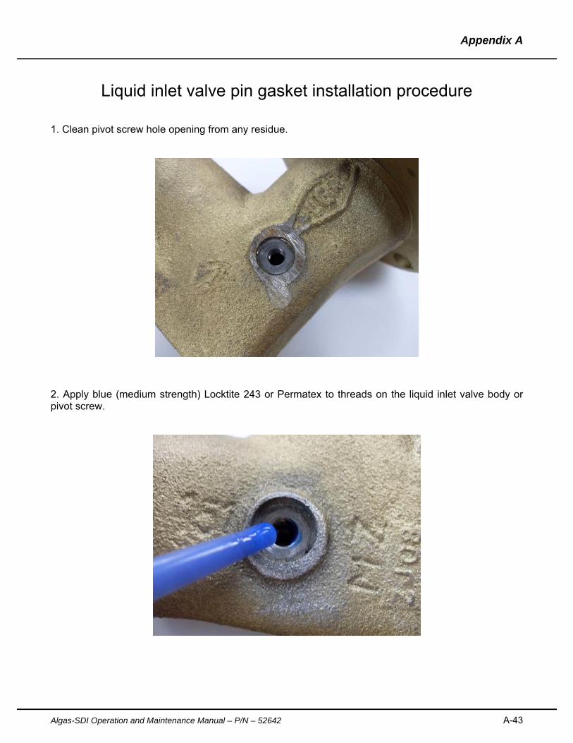
Liquid inlet valve pin gasket installation procedure
1. Clean pivot screw hole opening from any residue.
2. Apply blue (medium strength) Locktite 243 or Permatex to threads on the liquid inlet valve body or pivot screw.
Appendix A
A-44 Algas-SDI Operation and Maintenance Manual – P/N - 52642
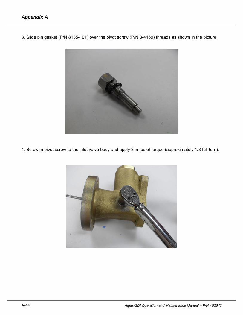
3. Slide pin gasket (P/N 8135-101) over the pivot screw (P/N 3-4169) threads as shown in the picture.
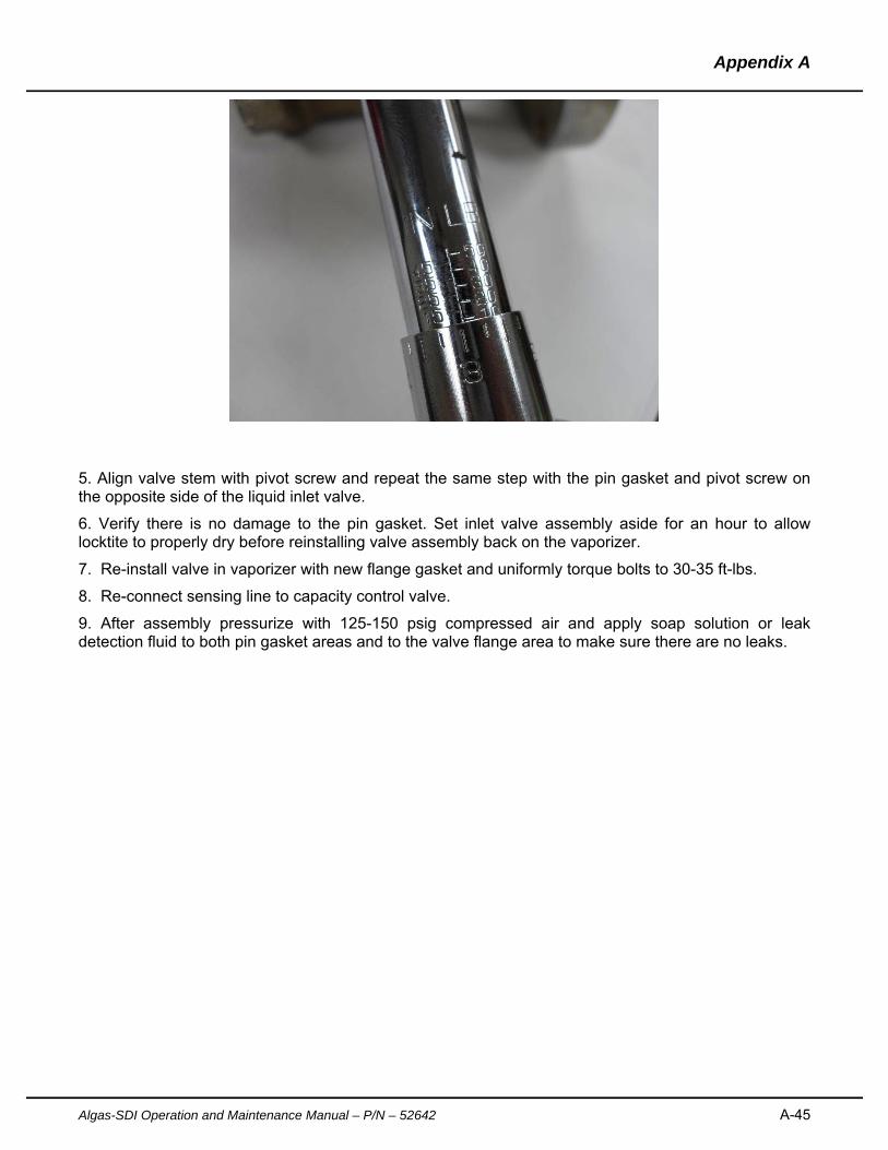
4. Screw in pivot screw to the inlet valve body and apply 8 in-lbs of torque (approximately 1/8 full turn).
Appendix A
Algas-SDI Operation and Maintenance Manual – P/N – 52642 A-45
5. Align valve stem with pivot screw and repeat the same step with the pin gasket and pivot screw on the opposite side of the liquid inlet valve.
6. Verify there is no damage to the pin gasket. Set inlet valve assembly aside for an hour to allow locktite to properly dry before reinstalling valve assembly back on the vaporizer.
7. Re-install valve in vaporizer with new flange gasket and uniformly torque bolts to 30-35 ft-lbs.
8. Re-connect sensing line to capacity control valve.
9. After assembly pressurize with 125-150 psig compressed air and apply soap solution or leak detection fluid to both pin gasket areas and to the valve flange area to make sure there are no leaks.


Algas-SDI International, LLC
151 South Michigan Street
Seattle, Washington, 98108
Ph: 1.206.789.5410
Fax: 1.206.789.5414
www.algas-sdi.com.