Operational Areas Soil Salvage Estimates
19
Operational Areas Soil Salvage Estimates Rosemont Copper June 2007
Transcript of Operational Areas Soil Salvage Estimates
Operational Areas Soil Salvage Estimates
Rosemont Copper
June 2007
i
Operational Areas Soil Salvage Estimates Rosemont Copper Prepared for:
Augusta Resource Corporation 4500 Cherry Creek South Drive, Suite #1040 Denver, Colorado 80246 (303) 300-0138 Fax (303) 300-0135
Prepared by:
136 East South Temple Salt Lake City, Utah 84111 (801) 364-1064 Fax (801) 364-2021 Tetra Tech Project No. 320614
June 2007
Operational Areas Soil Salvage Estimates Augusta Resource Corporation
Tetra Tech June 2007 i
TABLE OF CONTENTS
1.0 INTRODUCTION............................................................................................................... 1 1.1 Suitable Soil Areas ................................................................................................ 1 1.2 Northern Aspect – 12 inches ................................................................................. 2 1.3 Southern Aspect – 6-12 inches ............................................................................. 2 1.4 Alluvial Wash/Fans – 24-45 inches ....................................................................... 2 1.5 Alluvial Terraces – 18 inches ................................................................................ 2 1.6 Residual Benches – 12 inches .............................................................................. 2 1.7 Shallow to Bedrock – <6 inches ............................................................................ 3
2.0 ROSEMONT OPERATIONS AREAS ............................................................................... 4 2.1 Estimated Soil Salvage Volumes........................................................................... 4
3.0 CONSIDERATIONS.......................................................................................................... 5 4.0 REFERENCES.................................................................................................................. 6
LIST OF TABLES
Table 2.1: Operational Area and Salvageable Soil Volumes.................................................. 4
LIST OF FIGURES
Figure 1: Soil Map Unit Delineation Figure 2: Pre-Production Operations Area (Year 0) - Disturbed Area Map Figure 3: Year Five Operations Area - Disturbed Area Map Figure 4: Year Ten Operations Area - Disturbed Area Map Figure 5: Year Fifteen Operations Area - Disturbed Area Map Figure 6: Ultimate Operations Area - Disturbed Area Map
LIST OF APPENDICES
Appendix A: Table A -1: Operational Areas and Map Unit Intersection
Operational Areas Soil Salvage Estimates Augusta Resource Corporation
Tetra Tech June 2007 1
1.0 INTRODUCTION
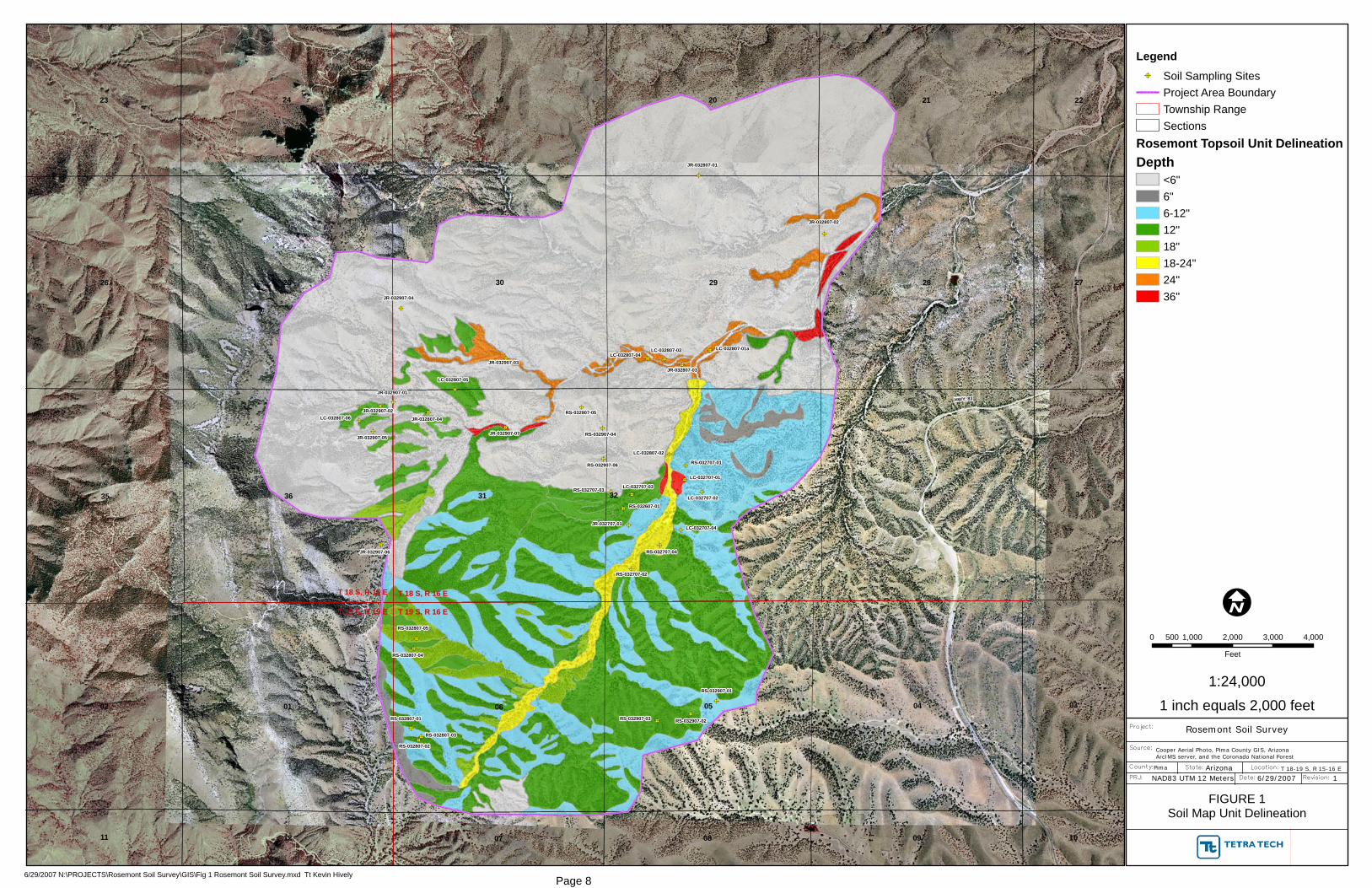
Reclamation of mined land is required under Arizona and Federal laws. Revegetation of the mined and disturbed areas is a primary focus of reclamation. Vegetation requires suitable growth media, soil, to become established. Definition of the available site soil resource that overlaps with mined or disturbed areas is needed to confirm that revegetation can be achieved. Within the operational areas a total of approximately 1,100 acres of the site will be disturbed. To cover the operational areas with a minimum 12 inches of soil that can support vegetation will require approximately 1,800,000 cubic yards of salvaged soil. This report estimates the soil salvage extents and volumes associated with the Rosemont operational areas. The estimates are based on Tetra Tech’s Survey of Salvage Topsoil Resources Report dated June 2007. The Survey of Salvage Topsoil Resources Report defines salvage soil thicknesses throughout the operations area and identifies their varying suitability as growth media. Suitable soil thicknesses ranging from less than 6 inches to more than 36 inches were identified. Determining suitable soils was based on generally accepted suitability characteristics. In addition, Tetra Tech indicated that material underlying the suitable soils may be used for the purposes of reclamation. Studies currently under way at the University of Arizona in Tucson will determine the suitability of these deeper subgrade materials as growth media. For the purposes of this evaluation, the deeper subgrade material is considered usable. The areas analyzed in the soil estimates for this report include the pit, haul roads, the heap leach pad and ponds and facility buildings. Table 2.1 lists the disturbed operational areas for years 0, 5, 10, 15, and Ultimate and salvaged soil volumes in these areas. Figure 1 describes the potential salvage soil within the project boundaries while Figures 2 through 6 presents the location of the cumulative disturbed operational areas superimposed on the salvage soil maps. A description of the site soil types are presented below along with a summary of the total estimated volume of material. The estimated total volume of salvage soil from the operational areas is 1,800,000 cubic yards. 1.1 Suitable Soil Areas In March 2007 Tetra Tech completed a detailed map of the onsite soil borrow depths within the proposed limits of the Rosemont Project Area. Since the map was completed, the limits of the project have changed slightly but the extent of the soil information remains largely inside the project limits. This map was based on a site soil resource evaluation and inventory field study completed by Tetra Tech. Detailed information from the study, including laboratory test results, soil profile logs and suitability criteria are provided in the Survey of Salvage Topsoil Resources Report (June 2007). The six map units within the project limits are described below. These six map units are further delineated into eight different borrow depths as presented on Figure 1. The availability of soil which can be salvaged in a particular area will be determined by the machinery used and the topographic disposition of the salvage area. Maximum salvage is achieved on flat ground where machinery function can be optimized.
Operational Areas Soil Salvage Estimates Augusta Resource Corporation
Tetra Tech June 2007 2
1.2 Northern Aspect – 12 inches North aspect soils located in the southern potion of the survey area are formed from colluvium and slope wash-alluvium. The geologic parent material of this area is of the Gila Conglomerate which consists of quartz sandstone, carbonates, argillite, hornfels, granitic rock and quartz –feldspar. The average depth of suitable borrow soil is approximately 12 inches. The soils available for salvage are sandy loams with 15 to 20% gravel, 0 to 5% cobbles and between 45 and 65% surface coarse fragments. Slopes range from 20 to 45 degrees. Generally these soils have moderate vegetative cover including trees, shrubs and grasses. 1.3 Southern Aspect – 6-12 inches South aspect soils located in the southern portion of the survey area are formed from colluvium and slope wash-alluvium. The geology of this area is also the Gila Conglomerate. These soils have approximately 6 inches of suitable soil for salvage with occasional deeper deposits in concave physiographic positions. The texture of these soils are sandy loam to coarse sandy loam with coarse fragment content on the surface ranges form 50 to 75% and coarse fragment content in the soil ranges 20 to 40% gravel and 0 to 5% cobbles. Slopes occurring in these areas range from 20 to 40 degrees. Vegetation cover is primarily forbes, cactus and grasses. 1.4 Alluvial Wash/Fans – 24-45 inches Alluvial washes are located in drainage bottoms throughout the project area. These soils are deep with borrow depths ranging from 24 to 45 inches and with textures of loamy sand to sandy loams. Coarse fragment content ranges from 15 to 45% consisting primarily of small gravels. Care will be needed with the active flood plain portions of the wash which generally have insufficient fines within the profile to support vegetation. Vegetation cover ranges from poor to very good dependent on the position of the site. The alluvial fans were limited in extent and were therefore included with the alluvial wash map unit. These fans are located at the mouths of side drainages and have the deepest soil salvage potential. The alluvial fan soil profile is very similar to the alluvial wash soils except that they are generally deeper with finer texture soils, generally loams rather than sandy loams. Vegetative cover in the fans also varies greatly depending on aspect and grazing pressure but is generally in a good class. 1.5 Alluvial Terraces – 18 inches This map unit is fairly limited and located in the western portion of the study. These soils are derived from Late Pleistocene alluvial terrace material at the toe of the upper slopes of the Santa Rita Mountains. They are deep gravelly to very gravelly loams over weakly cemented very reactive extremely gravelly alluvium. The salvageable borrow ranges from 12 to 18 inches with gravel and cobble generally being the restrictive feature. Vegetative production is good and is primarily comprised of grasses. 1.6 Residual Benches – 12 inches These map units are located in the northwestern portion of the project area. The majority of these soils are derived from very weathered residuum of the Willow Canyon Formation. These soils are moderately deep; however, borrow depths are generally limited to 1 foot due to coarse fragment content and heavy clay soils. Surface coarse fragment content ranges from 30 to 50%.
Operational Areas Soil Salvage Estimates Augusta Resource Corporation
Tetra Tech June 2007 3
Near surface texture are generally clay loams grading to clays with slopes varying greatly from 5 to 40% dependent on position. Vegetative cover varies from moderate to good. 1.7 Shallow to Bedrock – <6 inches The shallow bedrock unit is located in the center and northern portions of the project area. The major geologic formations include the Willow Canyon, an arkosic to tuffaceous siltstone, sandstone, and conglomerate; the Apache Canyon, a shale and laminated siltstone and the Mt. Fagan Rhyolite, an ash flow tuff. Soil depths range from very shallow to 5 inches on slopes, to deep 24 inches in drainages. The soils in this area range form coarse sandy loams to clay loams. Coarse fragments within the soil are between 25 and 45% gravels and surface fragments of 40 to 60% and higher. Some isolated pockets of borrow soil may be available on site specific basis. The limiting factor for suitable borrow soil in this area is the bedrock outcrops and shallow depth to bedrock throughout the majority of these areas. This material is the initial pedogenesis zone and generally not considered during soil salvage determination. However since the current vegetation cover primarily includes forbes, cactus and grasses, this indicates that the shallow bedrock unit is actively serving as a growth media. Soil suitability is being validated by growth media studies under way at the University of Arizona in Tucson. Revegetation success has been observed within the proposed pit area where weathered bedrock material has been used for reclamation at exploration locations.
Operational Areas Soil Salvage Estimates Augusta Resource Corporation
Tetra Tech June 2007 4
2.0 ROSEMONT OPERATIONS AREAS
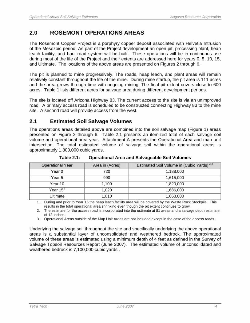
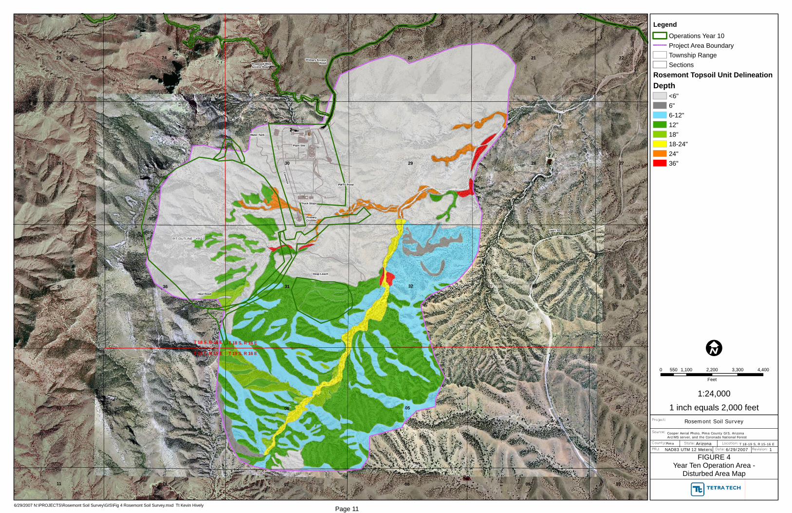
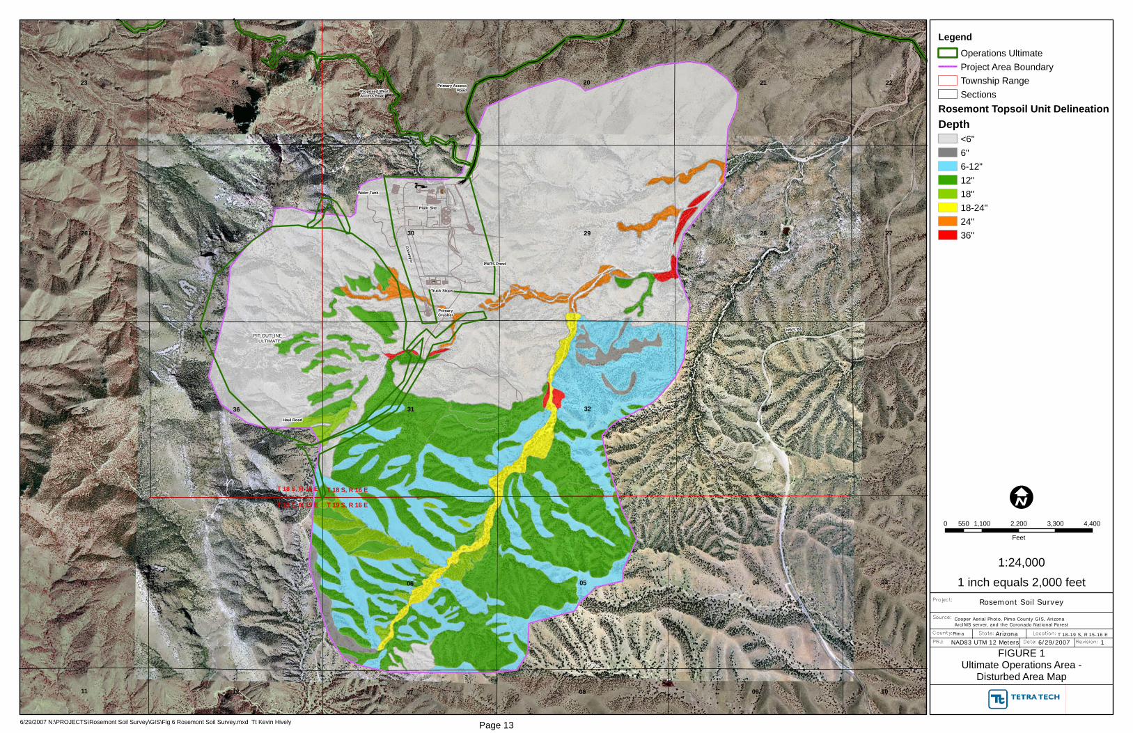
The Rosemont Copper Project is a porphyry copper deposit associated with Helvetia Intrusion of the Mesozoic period. As part of the Project development an open pit, processing plant, heap leach facility, and haul road system will be built. These operations will be in continuous use during most of the life of the Project and their extents are addressed here for years 0, 5, 10, 15, and Ultimate. The locations of the above areas are presented on Figures 2 through 6. The pit is planned to mine progressively. The roads, heap leach, and plant areas will remain relatively constant throughout the life of the mine. During mine startup, the pit area is 111 acres and the area grows through time with ongoing mining. The final pit extent covers close to 600 acres. Table 1 lists different acres for salvage area during different development periods. The site is located off Arizona Highway 83. The current access to the site is via an unimproved road. A primary access road is scheduled to be constructed connecting Highway 83 to the mine site. A second road will provide access from the west. 2.1 Estimated Soil Salvage Volumes The operations areas detailed above are combined into the soil salvage map (Figure 1) areas presented on Figure 2 through 6. Table 2.1 presents an itemized total of each salvage soil volume and operational area year. Attachment A presents the Operational Area and map unit intersection. The total estimated volume of salvage soil within the operational areas is approximately 1,800,000 cubic yards.
Table 2.1: Operational Area and Salvageable Soil Volumes Operational Year Area in (Acres) Estimated Soil Volume in (Cubic Yards) 2,3
Year 0 720 1,188,000 Year 5 990 1,615,000
Year 10 1,100 1,820,000 Year 151 1,020 1,686,000 Ultimate 1,010 1,668,000
1. During and prior to Year 15 the heap leach facility area will be covered by the Waste Rock Stockpile. This results in the total operational area shrinking even though the pit extent continues to grow.
2. The estimate for the access road is incorporated into the estimate at 81 areas and a salvage depth estimate of 12-inches.
3. Operational Areas outside of the Map Unit Areas are not included except in the case of the access roads. Underlying the salvage soil throughout the site and specifically underlying the above operational areas is a substantial layer of unconsolidated and weathered bedrock. The approximated volume of these areas is estimated using a minimum depth of 4 feet as defined in the Survey of Salvage Topsoil Resources Report (June 2007). The estimated volume of unconsolidated and weathered bedrock is 7,100,000 cubic yards .
Operational Areas Soil Salvage Estimates Augusta Resource Corporation
Tetra Tech June 2007 5
3.0 CONSIDERATIONS
When implementing the soil salvage activities the following items are offered for consideration:
• The typical salvage soil can likely make a viable growing media. Considering the desert nature of the area a high coarse soil percentage will help to keep the soil in place during occasional extreme erosion events;
• Observed native plant growth on the site is on the Northern aspects. This is attributable to the locally high aridity index which is more severe on southern exposures. When practicable, sloping reclaimed areas to the north will aide the re-vegetation effort.
• Salvage of some of the underlying fractured bedrock will effectively increase the salvage volume without severely degrading the salvage soil quality.
Operational Areas Soil Salvage Estimates Augusta Resource Corporation
Tetra Tech June 2007 6
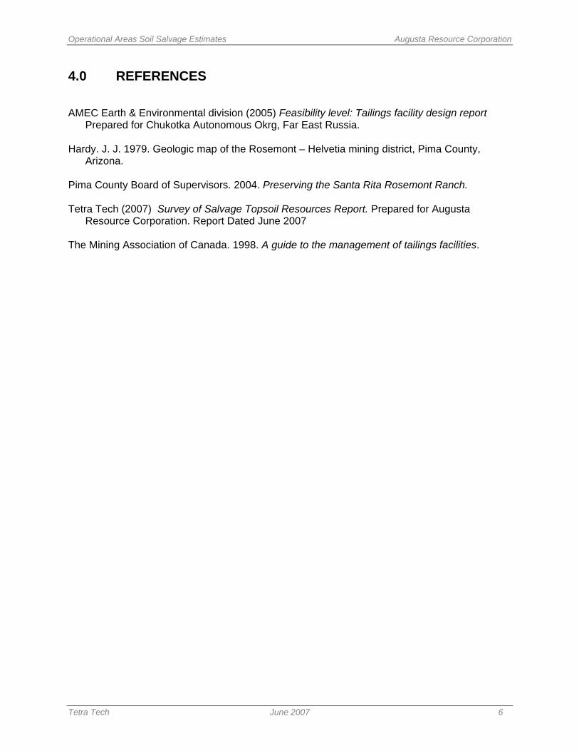
4.0 REFERENCES
AMEC Earth & Environmental division (2005) Feasibility level: Tailings facility design report
Prepared for Chukotka Autonomous Okrg, Far East Russia. Hardy. J. J. 1979. Geologic map of the Rosemont – Helvetia mining district, Pima County,
Arizona. Pima County Board of Supervisors. 2004. Preserving the Santa Rita Rosemont Ranch. Tetra Tech (2007) Survey of Salvage Topsoil Resources Report. Prepared for Augusta
Resource Corporation. Report Dated June 2007 The Mining Association of Canada. 1998. A guide to the management of tailings facilities.

FIGURES
!A
!A
!A
!A
!A
!A
!A
!A!A
!A
!A
!A
!A!A
!A
!A!A
!A
!A
!A
!A!A
!A
!A
!A
!A
!A
!A
!A
!A
!A!A
!A
!A
!A
!A!A
!A
HWY. 83
T 18 S, R 15 E
T 19 S, R 15 E T 19 S, R 16 E
T 18 S, R 16 E
LC-032807-01a
RS-032707-01
RS-032707-03
LC-032707-04
JR-032807-03
RS-032807-01
JR-032907-01
RS-032607-01
JR-032707-01
RS-032707-02
RS-032707-04
LC-032707-01
LC-032707-02
LC-032707-03
JR-032807-01
JR-032807-02
LC-032807-03LC-032807-04
LC-032807-05
LC-032807-06
RS-032807-03
RS-032807-04
RS-032807-05
JR-032907-03
JR-032907-05
JR-032907-06
JR-032907-07
RS-032907-01
RS-032907-02RS-032907-03
RS-032907-04
RS-032907-05
RS-032907-06
JR-032807-04JR-032907-02
JR-032907-04
LC-032807-02
0
RS-032807-02
30
32
28
31
29
33
25
36
06 0401 05
35
26
2119 20
02
2423
03
27
34
22
0912 080711 10
FIGURE 1Soil Map Unit Delineation
Project:
County:
PRJ:
State: Location:
Date: Revision:
Pima
Rosemont Soil Survey
Arizona T 18-19 S, R 15-16 E
6/29/2007 1
I0 1,000 2,000 3,000 4,000500
Feet
Source: Cooper Aerial Photo, Pima County GIS, ArizonaArcIMS server, and the Coronado National Forest
NAD83 UTM 12 Meters
6/29/2007 N:\PROJECTS\Rosemont Soil Survey\GIS\Fig 1 Rosemont Soil Survey.mxd Tt Kevin Hively
1:24,0001 inch equals 2,000 feet
Legend!A Soil Sampling Sites
Project Area BoundaryTownship RangeSections
Rosemont Topsoil Unit DelineationDepth
<6"6"6-12"12"18"18-24"24"36"
Page 8

Plant Site
Conveyor
PWTS Pond
Truck Stops
PrimaryCrusher
Water Tank
Primary AccessRoadProposed West
Access Road
HWY. 83
PIT OUTLINE - PRE-PRODUCTION
T 18 S, R 15 E
T 19 S, R 15 E T 19 S, R 16 E
T 18 S, R 16 E
Haul Road
Heap Leach
30
32
28
31
29
33
25
36
06 0401 05
35
26
2119 20
02
2423
03
27
34
22
0912 080711 10
FIGURE 2Pre-Production Operations Area(Year 0) - Disturbed Area Map
Project:
County:
PRJ:
State: Location:
Date: Revision:
Pima
Rosemont Soil Survey
Arizona T 18-19 S, R 15-16 E
6/29/2007 1
I0 1,000 2,000 3,000 4,000500
Feet
Source: Cooper Aerial Photo, Pima County GIS, ArizonaArcIMS server, and the Coronado National Forest
NAD83 UTM 12 Meters
6/29/2007 N:\PROJECTS\Rosemont Soil Survey\GIS\Fig 2 Rosemont Soil Survey.mxd Tt Kevin Hively
1:24,0001 inch equals 2,000 feet
LegendOperational Pre-ProductionProject Area BoundaryTownship RangeSections
Rosemont Topsoil Unit DelineationDepth
<6"6"6-12"12"18"18-24"24"36"
Page 9

Plant Site
Conveyor
PWTS Pond
Truck Stops
PrimaryCrusher
Water Tank
Primary AccessRoadProposed West
Access Road
HWY. 83
PIT OUTLINE - YR 05
T 18 S, R 15 E
T 19 S, R 15 E T 19 S, R 16 E
T 18 S, R 16 E
Haul Road
Heap Leach
30
32
28
31
29
33
25
36
06 0401 05
35
26
2119 20
02
2423
03
27
34
22
0912 080711 10
FIGURE 3Year Five Operation Area -
Disturbed Area Map
Project:
County:
PRJ:
State: Location:
Date: Revision:
Pima
Rosemont Soil Survey
Arizona T 18-19 S, R 15-16 E
6/29/2007 1
I0 1,000 2,000 3,000 4,000500
Feet
Source: Cooper Aerial Photo, Pima County GIS, ArizonaArcIMS server, and the Coronado National Forest
NAD83 UTM 12 Meters
6/29/2007 N:\PROJECTS\Rosemont Soil Survey\GIS\Fig 3 Rosemont Soil Survey.mxd Tt Kevin Hively
1:24,0001 inch equals 2,000 feet
LegendOperations Year 05Project Area BoundaryTownship RangeSections
Rosemont Topsoil Unit DelineationDepth
<6"6"6-12"12"18"18-24"24"36"
Page 10
Plant Site
Conveyor
PWTS Pond
Truck Stops
PrimaryCrusher
Water Tank
Primary AccessRoadProposed West
Access Road
HWY. 83
PIT OUTLINE - YR 10
T 18 S, R 15 E
T 19 S, R 15 E T 19 S, R 16 E
T 18 S, R 16 E
Haul Road
Heap Leach
30
32
28
31
29
33
25
36
06 0401 05
35
26
2119 20
02
2423
03
27
34
22
0912 080711 10
FIGURE 4Year Ten Operation Area -
Disturbed Area Map
Project:
County:
PRJ:
State: Location:
Date: Revision:
Pima
Rosemont Soil Survey
Arizona T 18-19 S, R 15-16 E
6/29/2007 1
I0 1,100 2,200 3,300 4,400550
Feet
Source: Cooper Aerial Photo, Pima County GIS, ArizonaArcIMS server, and the Coronado National Forest
NAD83 UTM 12 Meters
6/29/2007 N:\PROJECTS\Rosemont Soil Survey\GIS\Fig 4 Rosemont Soil Survey.mxd Tt Kevin Hively
1:24,0001 inch equals 2,000 feet
LegendOperations Year 10Project Area BoundaryTownship RangeSections
Rosemont Topsoil Unit DelineationDepth
<6"6"6-12"12"18"18-24"24"36"
Page 11

Plant Site
Conveyor
PWTS Pond
Truck Stops
PrimaryCrusher
Water Tank
Primary AccessRoadProposed West
Access Road
HWY. 83
PIT OUTLINE - (YR-15)
T 18 S, R 15 E
T 19 S, R 15 E T 19 S, R 16 E
T 18 S, R 16 E
Haul Road
30
32
28
31
29
33
25
36
06 0401 05
35
26
2119 20
02
2423
03
27
34
22
0912 080711 10
FIGURE 5Year 15 Operation Area -
Disturbed Area Map
Project:
County:
PRJ:
State: Location:
Date: Revision:
Pima
Rosemont Soil Survey
Arizona T 18-19 S, R 15-16 E
6/29/2007 1
I0 1,100 2,200 3,300 4,400550
Feet
Source: Cooper Aerial Photo, Pima County GIS, ArizonaArcIMS server, and the Coronado National Forest
NAD83 UTM 12 Meters
6/29/2007 N:\PROJECTS\Rosemont Soil Survey\GIS\Fig 5 Rosemont Soil Survey.mxd Tt Kevin Hively
1:24,0001 inch equals 2,000 feet
LegendOperations Year 15Project Area BoundaryTownship RangeSections
Rosemont Topsoil Unit DelineationDepth
<6"6"6-12"12"18"18-24"24"36"
Page 12
Plant Site
Conveyor
PWTS Pond
Truck Stops
PrimaryCrusher
Water Tank
Primary AccessRoadProposed West
Access Road
HWY. 83
PIT OUTLINE - ULTIMATE
T 18 S, R 15 E
T 19 S, R 15 E T 19 S, R 16 E
T 18 S, R 16 E
Haul Road
30
32
28
31
29
33
25
36
06 0401 05
35
26
2119 20
02
2423
03
27
34
22
0912 080711 10
FIGURE 1Ultimate Operations Area -
Disturbed Area Map
Project:
County:
PRJ:
State: Location:
Date: Revision:
Pima
Rosemont Soil Survey
Arizona T 18-19 S, R 15-16 E
6/29/2007 1
I0 1,100 2,200 3,300 4,400550
Feet
Source: Cooper Aerial Photo, Pima County GIS, ArizonaArcIMS server, and the Coronado National Forest
NAD83 UTM 12 Meters
6/29/2007 N:\PROJECTS\Rosemont Soil Survey\GIS\Fig 6 Rosemont Soil Survey.mxd Tt Kevin Hively
1:24,0001 inch equals 2,000 feet
LegendOperations UltimateProject Area BoundaryTownship RangeSections
Rosemont Topsoil Unit DelineationDepth
<6"6"6-12"12"18"18-24"24"36"
Page 13
Vector Arizona
Text Box
6
APPENDIX A OPERATIONAL AREA AND MAP UNIT INTERSECTION
Operational Areas Soil Salvage Estimates Augusta Resource Corporation
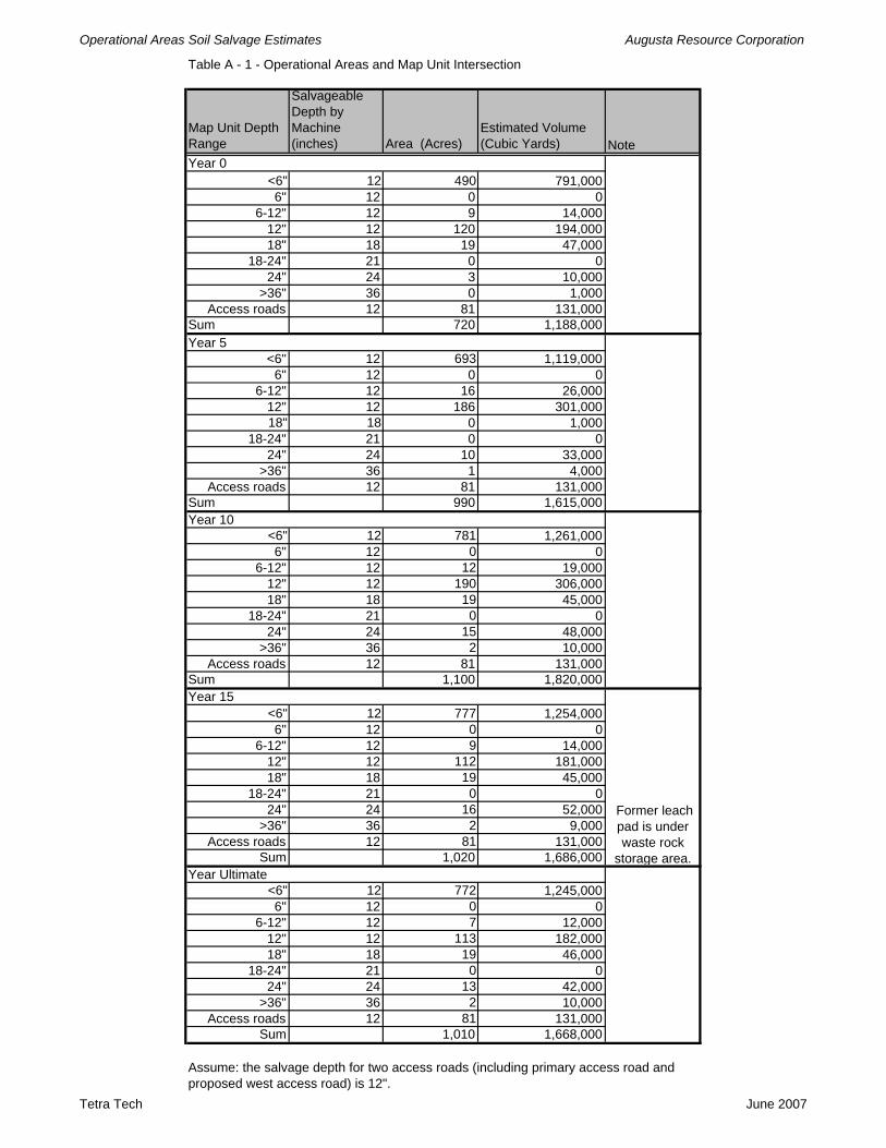
Table A - 1 - Operational Areas and Map Unit Intersection
Map Unit Depth Range
Salvageable Depth by Machine (inches) Area (Acres)
Estimated Volume (Cubic Yards) Note
<6" 12 490 791,0006" 12 0 0
6-12" 12 9 14,00012" 12 120 194,00018" 18 19 47,000
18-24" 21 0 024" 24 3 10,000
>36" 36 0 1,000Access roads 12 81 131,000
Sum 720 1,188,000
<6" 12 693 1,119,0006" 12 0 0
6-12" 12 16 26,00012" 12 186 301,00018" 18 0 1,000
18-24" 21 0 024" 24 10 33,000
>36" 36 1 4,000Access roads 12 81 131,000
Sum 990 1,615,000
<6" 12 781 1,261,0006" 12 0 0
6-12" 12 12 19,00012" 12 190 306,00018" 18 19 45,000
18-24" 21 0 024" 24 15 48,000
>36" 36 2 10,000Access roads 12 81 131,000
Sum 1,100 1,820,000
<6" 12 777 1,254,0006" 12 0 0
6-12" 12 9 14,00012" 12 112 181,00018" 18 19 45,000
18-24" 21 0 024" 24 16 52,000
>36" 36 2 9,000Access roads 12 81 131,000
Sum 1,020 1,686,000
<6" 12 772 1,245,0006" 12 0 0
6-12" 12 7 12,00012" 12 113 182,00018" 18 19 46,000
18-24" 21 0 024" 24 13 42,000
>36" 36 2 10,000Access roads 12 81 131,000
Sum 1,010 1,668,000
Assume: the salvage depth for two access roads (including primary access road and proposed west access road) is 12".
Year Ultimate
Former leach pad is under waste rock
storage area.
Year 0
Year 5
Year 10
Year 15
Tetra Tech June 2007