
Operation & Service Manual - Columbus McKinnon YK Series...demostrada en la reparación de equipos y...
102
ba-o.2.6.0-us-1.1-y | A11867501 Rev AA Before installing hoist, fill in the information below. Refer to the Hoist and Motor data plates. Model No. ____________________________________________ Serial No. ____________________________________________ Purchase Date ____________________________________________ Voltage ____________________________________________ Rated Load ____________________________________________ Follow all instructions and warnings for inspecting, maintaining and operating this hoist. The use of any hoist presents some risk of personal injury or property damage. That risk is greatly increased if proper instructions and warnings are not followed. Before using this hoist, each operator should become thoroughly familiar with all warnings, instructions and recommendations in this manual. Retain this manual for future reference and use. Forward this manual to operator. Failure to operate equipment as directed in manual may cause injury. Wire Rope Hoists Operation & Service Manual
Transcript of Operation & Service Manual - Columbus McKinnon YK Series...demostrada en la reparación de equipos y...

ba-o
.2.6
.0-u
s-1.
1-y
| A
1186
7501
Rev
AA
Before installing hoist, fill in the information below. Refer to the Hoist and Motor data plates.
Model No. ____________________________________________
Serial No. ____________________________________________
Purchase Date ____________________________________________
Voltage ____________________________________________
Rated Load ____________________________________________
Follow all instructions and warnings for inspecting, maintaining and operating this hoist.
The use of any hoist presents some risk of personal injury or property damage. That risk is greatly increased if proper instructions and warnings are not followed. Before using this hoist, each operator should become thoroughly familiar with all warnings, instructions and recommendations in this manual. Retain this manual for future reference and use.
Forward this manual to operator. Failure to operate equipment as directed in manual may cause injury.
Wire Rope Hoists
Operation & Service Manual

ba-o
.2.6
.0-u
s-1.
1-y
| A
1186
7501
Rev
AA
YALE/SHAWBOX HOIST PARTS AND SERVICES ARE AVAILABLE IN THE UNITED STATES AND IN CANADA
As a Yale/Shawbox Hoist and Trolley user you are assured of reliable repair and parts services through a network of Master Parts Depots and Service Centers that are strategically located in the United States and Canada. These facilities have been selected on the basis of their demonstrated ability to handle all parts and repair requirements promptly and efficiently. To quickly obtain the name of the Master Parts Depot or Service Center located nearest you, call (800) 888-0985, Fax: (716) 689-5644, visit www.cmworks.com
LAS PIEZAS Y REPARACIONES DE LOS POLIPASTOS DE YALE/SHAWBOX ESTÁN ASEGURADAS EN ESTADOS UNIDOS Y CANADÁ
Como usuario de un polipasto y carro de Yale/Shawbox le aseguramos cualquier reparación o la disponibilidad de cualquier pieza de repuesto a través de una red de almacenes de piezas de repuesto y centros de servicio situados estratégicamente en Estados Unidos y Canadá. Estas instalaciones se han seleccionado en base a su capacidad demostrada en la reparación de equipos y suminstro de piezas de repuesto de forma rápida y eficaz. Para obtener la dirección del almacén de piezas de repuesto o del centro de servicio más cercano, llame al teléfono (800) 888-0985. Fax: (716) 689-5644, visite www.cmworks.com (sólo en Estados Unidos y Canadá).
LE SERVICE DE RÉPARATION ET DE PIÈCES POUR PALANS YALE/SHAWBOX EST DISPONIBLE AUX ÉTATS-UNIS ET AU CANADA
Soyez assurés qu'en temps d'utilisateur de palan et treuil Yale/Shawbox, d'un service de réparation et de pièces fiable par l'entremise d'un réseau de Centres de service et de Dépôts de pièces maîtresses qui sont stratégiquement situés aux États-Unis et au Canada. Ces établissements ont été sélectionnés sur une base de leur habileté démontrée à s'occuper promptement et efficacement des besoins de réparation de pièces. Appelez le (800) 888-0985, Fax: (716) 689-5644, visite www.cmworks.com pour obtenir rapidement le nom du dépôt de pièces maîtresses ou du centre de service situé le plus près.

03.2018 3
ba-o
.2.6
.0-u
s-1.
1-y
| A
1186
7501
Rev
AA
Contents
1 General information ................................................................................................................................................................................................ 6 1.1 Information about safety messages .................................................................................................................................................................... 6
1.1.1 Explanation of signal words and symbols ..................................................................... 6 1.1.2 Safety instructions ........................................................................................................... 6 1.1.3 Section safety messages ................................................................................................ 6 1.1.4 Embedded safety messages .......................................................................................... 6 1.1.5 Safety alert symbols ........................................................................................................ 7 1.1.6 Additional symbol ............................................................................................................ 7
1.2 Spare parts ................................................................................................................................................................................................................ 7 1.3 Target audience and responsibilities .................................................................................................................................................................. 7 1.4 Crane logbook .......................................................................................................................................................................................................... 8 1.5 Transport and storage ............................................................................................................................................................................................ 8 1.6 Weight ........................................................................................................................................................................................................................ 8 1.7 Installation, commissioning, maintenance and repairs ................................................................................................................................... 8 1.8 After-sales service ................................................................................................................................................................................................... 9 1.9 Periodic inspections ............................................................................................................................................................................................... 9 1.10 Environmental information .................................................................................................................................................................................... 9
1.10.1 Life cycle assessment ..................................................................................................... 9 1.10.2 Energy consumption ....................................................................................................... 9
2 General safety notes ............................................................................................................................................................................................. 10 2.1 Use for intended purpose .................................................................................................................................................................................... 10 2.2 Inappropriate use ................................................................................................................................................................................................... 10 2.3 Residual hazards ................................................................................................................................................................................................... 11 2.4 Organizational safety precautions ..................................................................................................................................................................... 11 2.5 General regulations ............................................................................................................................................................................................... 11 2.6 Recommended PPE .............................................................................................................................................................................................. 11 2.7 Working above floor level .................................................................................................................................................................................... 12 2.8 Sound pressure level ............................................................................................................................................................................................ 12 2.9 Fire safety ................................................................................................................................................................................................................ 12 2.10 Safety-conscious operation ................................................................................................................................................................................ 13 2.11 Attaching load ........................................................................................................................................................................................................ 13 3 Introduction ............................................................................................................................................................................................................ 14 3.1 Incorporation .......................................................................................................................................................................................................... 15 4 Installation ............................................................................................................................................................................................................... 16 4.1 Stationary hoist ...................................................................................................................................................................................................... 16
4.1.1 Attachment at bottom .................................................................................................... 17 4.1.2 Attachment at top .......................................................................................................... 19
4.2 Fleet angle ............................................................................................................................................................................................................... 20 4.2.1 Attachment at bottom .................................................................................................... 20 4.2.2 Attachment at top .......................................................................................................... 21 4.2.3 Attachment at side ......................................................................................................... 22 4.2.4 Fleet angle ..................................................................................................................... 23 4.2.5 Angle of installation ....................................................................................................... 23
4.3 Monorail trolleys .................................................................................................................................................................................................... 24 4.3.1 Monorail trolley (KE-S33 - 76) ...................................................................................... 24 4.3.2 Drive shaft for travel drive (trolleys KE-S33 - KE-S65) ............................................... 25 4.3.3 Drive shaft for trolley drive (trolley KE-S76) ................................................................. 26 4.3.4 Monorail trolley (UE-S4) ................................................................................................ 27 4.3.5 Monorail trolley (UE-S776) ........................................................................................... 29 4.3.6 Articulated trolley (DKE-S4 / DKE-S6) ......................................................................... 31
4.4 End stops for monorail trolleys .......................................................................................................................................................................... 34 4.5 Double rail trolley (OE-S) ...................................................................................................................................................................................... 35 4.6 End stops for double rail trolleys ....................................................................................................................................................................... 36
4.6.1 Wheel diameter D = 3.9 in. ........................................................................................... 36 4.6.2 Wheel diameter D = 4.9 - 7.9 in.................................................................................... 36
4.7 Anti-jump catch ...................................................................................................................................................................................................... 37 4.7.1 Description of system .................................................................................................... 37 4.7.2 Procedure ....................................................................................................................... 37
4 03.2018
ba-o
.2.6
.0-u
s-1.
1-y
| A
1186
7501
Rev
AA
4.8 Travel limit switches ............................................................................................................................................................................................. 40 4.8.1 Monorail trolley ............................................................................................................... 40 4.8.2 Double rail trolley ........................................................................................................... 40
4.9 Electrical equipment ............................................................................................................................................................................................. 41 4.9.1 Supply cables................................................................................................................. 41 4.9.2 Terminals........................................................................................................................ 41 4.9.3 Protection of equipment ................................................................................................ 42 4.9.4 Emergency stop ............................................................................................................. 42 4.9.5 Runway conductor disconnecting means .................................................................... 42 4.9.6 Disconnect switch .......................................................................................................... 42 4.9.7 Connection fuses ........................................................................................................... 42 4.9.8 Electromagnetic compatibility ....................................................................................... 43 4.9.9 Overload safety device.................................................................................................. 44 4.9.10 Connecting to mains...................................................................................................... 45 4.9.11 Control and control functions ........................................................................................ 46 4.9.12 Electric motors and related equipment ........................................................................ 47
4.10 YK/SK hoists with frequency inverter (VFD) .................................................................................................................................................... 47 4.11 Reeving rope .......................................................................................................................................................................................................... 48 5 Commissioning ...................................................................................................................................................................................................... 53 6 Operating................................................................................................................................................................................................................. 54 6.1 Operating precautions .......................................................................................................................................................................................... 54 6.2 Duties of crane operator....................................................................................................................................................................................... 56 6.3 Using control pendant .......................................................................................................................................................................................... 57 6.4 Operating hoist with frequency inverter ........................................................................................................................................................... 58 6.5 Emergency stop ..................................................................................................................................................................................................... 58 7 Inspection and maintenance ............................................................................................................................................................................... 59 7.1 Inspection intervals ............................................................................................................................................................................................... 60 7.2 Maintenance intervals ........................................................................................................................................................................................... 61 7.3 Motors ...................................................................................................................................................................................................................... 62 7.4 Hoist motor brake (RSM) ...................................................................................................................................................................................... 63
7.4.1 Checking brake .............................................................................................................. 63 7.4.2 Replacing brake disk (brake rotor) ............................................................................... 63
7.5 Hoist motor brake (NM) (pole-changing) ........................................................................................................................................................... 64 7.5.1 Checking brake .............................................................................................................. 64 7.5.2 Replacing brake disk (brake rotor) ............................................................................... 64
7.6 Hoist motor brake (NM) (4-pole) .......................................................................................................................................................................... 65 7.6.1 Checking brake .............................................................................................................. 65 7.6.2 Replacing brake disk (brake rotor ................................................................................ 65
7.7 Hoist motor brake (NM) 4HS. ............................................................................................................................................................................... 67 7.7.1 Checking brake .............................................................................................................. 67 7.7.2 Replacing brake disk (brake rotor) ............................................................................... 67
7.8 Travel motor brake ................................................................................................................................................................................................ 68 7.9 Hoist limit switch ................................................................................................................................................................................................... 69
7.9.1 Hoist limit switch (standard) .......................................................................................... 69 7.10 Hoist limit switch ................................................................................................................................................................................................... 70
7.10.1 Description of hoist limit switch system ........................................................................ 70 7.10.2 Testing emergency hoist limit switch, version 1 .......................................................... 70 7.10.3 Testing operational hoist limit switch, version 1 .......................................................... 70 7.10.4 Testing emergency hoist limit switch, version 2 .......................................................... 71 7.10.5 Testing operational hoist limit switch, version 2 .......................................................... 71 7.10.6 Setting hoist limit switch ................................................................................................ 72 7.10.7 Servicing hoist limit switch ............................................................................................ 75
7.11 Hook dimensions C for KE-S.. trolleys .............................................................................................................................................................. 76 7.12 Overload safety device ......................................................................................................................................................................................... 77
7.12.1 Testing overload safety device ..................................................................................... 77 7.12.2 Maintenance of overload safety device with pressure sensor ................................... 77 7.12.3 Maintenance of overload safety device with shear force sensor ............................... 77
7.13 Crane test ................................................................................................................................................................................................................ 77 7.14 Rope drive ............................................................................................................................................................................................................... 78
7.14.1 Rope and rope attachment - general information ....................................................... 78 7.14.2 Replacement of wire rope due to broken wires ........................................................... 79

03.2018 5
ba-o
.2.6
.0-u
s-1.
1-y
| A
1186
7501
Rev
AA
7.14.3 Removing rope guide .................................................................................................... 79 7.14.4 Replacing wire rope ....................................................................................................... 80 7.14.5 Fitting rope guide ........................................................................................................... 81 7.14.6 Checking rope drum for wear ....................................................................................... 82 7.14.7 Inspection and maintenance of rope sheave .............................................................. 83 7.14.8 Checking load hook ....................................................................................................... 84
7.15 Trolley ...................................................................................................................................................................................................................... 85 7.16 Remaining service life .......................................................................................................................................................................................... 86
7.16.1 Operating hours counter in SLE load monitor ............................................................. 86 7.16.2 SMC multi-controller (optional) ..................................................................................... 86
7.17 General overhaul ................................................................................................................................................................................................... 86 8 Wearing parts ......................................................................................................................................................................................................... 87 8.1 Serial number ......................................................................................................................................................................................................... 87 8.2 Hoist ......................................................................................................................................................................................................................... 87 9 Troubleshooting .................................................................................................................................................................................................... 89 10 Decommissioning ................................................................................................................................................................................................. 91 10.1 Dismantling ............................................................................................................................................................................................................. 91 10.2 Scrap disposal ....................................................................................................................................................................................................... 91 11 Technical data ........................................................................................................................................................................................................ 92 11.1 Conditions of use .................................................................................................................................................................................................. 92 11.2 Hoist ......................................................................................................................................................................................................................... 93
11.2.1 Pole-changing hoist motors ../…-MF 50Hz ................................................................. 93 11.2.2 Pole-changing hoist motors ../…-MF 60Hz ................................................................. 94 11.2.3 Pole-changing hoist motors 50Hz ................................................................................ 95 11.2.4 Pole-changing hoist motors 60Hz ................................................................................ 95 11.2.5 Frequency-controlled hoist motors ../4H..-MF 100 Hz ................................................ 96 11.2.6 Frequency-controlled hoist motors ../4H..-MF 120 Hz ................................................ 96 11.2.7 Frequency-controlled hoist motors ../4HS.-MF 100 Hz .............................................. 97 11.2.8 Frequency-controlled hoist motors ../4HS.-MF 120 Hz .............................................. 97
11.3 Cable cross sections and lengths of supply cable ......................................................................................................................................... 98 11.3.1 Cable cross sections and lengths of supply cable for pole-changing hoist motors …-
MF ................................................................................................................................... 98 11.3.2 Cable cross sections and lengths of supply cable for pole-changing hoist motors .. 98
11.4 Tightening torques ................................................................................................................................................................................................ 99 11.5 Lubricants ............................................................................................................................................................................................................. 101 11.6 Lubricants for travel drive .................................................................................................................................................................................. 101 11.7 Circuit diagrams .................................................................................................................................................................................................. 101

1 General information
6 03.2018
ba-o
.2.6
.0-u
s-1.
1-y
| A
1186
7501
Rev
AA
1 General information
You have purchased a Yale product. This product was constructed in accordance with the applicable European standards and regulations. Read carefully and observe this manual. Store the manual within easy reach at the place of operation.
1.1 Information about safety messages
1.1.1 Explanation of signal words and symbols
The following signal words are used in safety messages.
Signal word Meaning
DANGER Indicates a hazardous situation which, if not avoided, will result in death or serious injury.
WARNING Indicates a hazardous situation which, if not avoided, could result in death or serious injury.
CAUTION Indicates a hazardous situation which, if not avoided, could result in minor or moderate injury.
NOTICE Indicates possible material or environmental damage.
1.1.2 Safety instructions
The fundamental hazards and required safety measures are listed in section “General safety notes”. 1.1.3 Section safety messages
Section safety messages relate to an entire section and are laid out as follows.
SIGNAL WORD
Type and source of hazard Possible consequences if disregarded ➢ Measures to prevent the hazard
1.1.4 Embedded safety messages
Embedded safety messages are placed directly before or after a required action and are structured as follows.
SIGNAL WORD Type and source of hazard, possible consequences if disregarded.
➢ Measures to prevent the hazard,
1 General information
03.2018 7
ba-o
.2.6
.0-u
s-1.
1-y
| A
1186
7501
Rev
AA
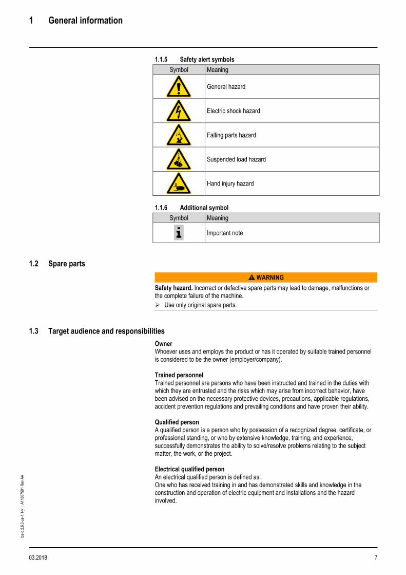
1.1.5 Safety alert symbols
Symbol Meaning
General hazard
Electric shock hazard
Falling parts hazard
Suspended load hazard
Hand injury hazard
1.1.6 Additional symbol
Symbol Meaning
Important note
1.2 Spare parts
WARNING
Safety hazard. Incorrect or defective spare parts may lead to damage, malfunctions or the complete failure of the machine.
➢ Use only original spare parts.
1.3 Target audience and responsibilities
Owner Whoever uses and employs the product or has it operated by suitable trained personnel is considered to be the owner (employer/company). Trained personnel Trained personnel are persons who have been instructed and trained in the duties with which they are entrusted and the risks which may arise from incorrect behavior, have been advised on the necessary protective devices, precautions, applicable regulations, accident prevention regulations and prevailing conditions and have proven their ability. Qualified person A qualified person is a person who by possession of a recognized degree, certificate, or professional standing, or who by extensive knowledge, training, and experience, successfully demonstrates the ability to solve/resolve problems relating to the subject matter, the work, or the project. Electrical qualified person An electrical qualified person is defined as: One who has received training in and has demonstrated skills and knowledge in the construction and operation of electric equipment and installations and the hazard involved.
1 General information
8 03.2018
ba-o
.2.6
.0-u
s-1.
1-y
| A
1186
7501
Rev
AA
1.4 Crane logbook
A completed crane logbook must be kept for each hoist. The results of the periodic inspections must be entered in the logbook.
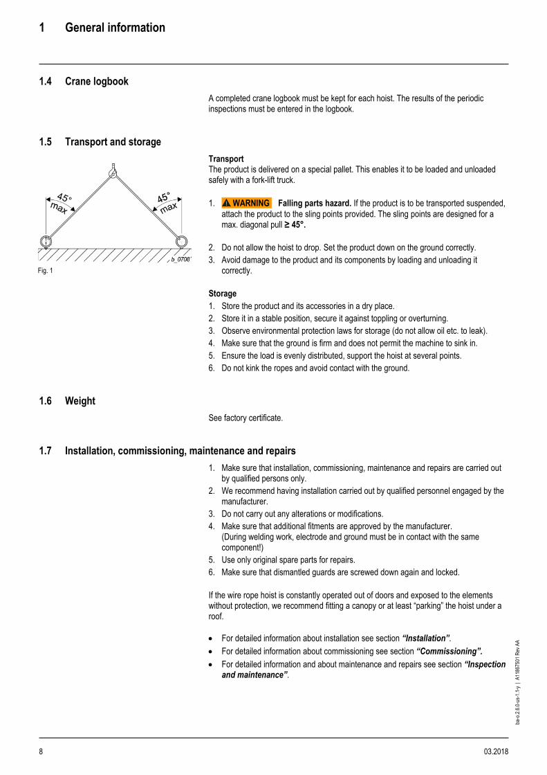
1.5 Transport and storage
Transport
Fig. 1
The product is delivered on a special pallet. This enables it to be loaded and unloaded safely with a fork-lift truck.
1. WARNING Falling parts hazard. If the product is to be transported suspended,
attach the product to the sling points provided. The sling points are designed for a max. diagonal pull ≥ 45°.
2. Do not allow the hoist to drop. Set the product down on the ground correctly.
3. Avoid damage to the product and its components by loading and unloading it correctly.
Storage
1. Store the product and its accessories in a dry place.
2. Store it in a stable position, secure it against toppling or overturning.
3. Observe environmental protection laws for storage (do not allow oil etc. to leak).
4. Make sure that the ground is firm and does not permit the machine to sink in.
5. Ensure the load is evenly distributed, support the hoist at several points.
6. Do not kink the ropes and avoid contact with the ground.
1.6 Weight
See factory certificate.
1.7 Installation, commissioning, maintenance and repairs
1. Make sure that installation, commissioning, maintenance and repairs are carried out by qualified persons only.
2. We recommend having installation carried out by qualified personnel engaged by the manufacturer.
3. Do not carry out any alterations or modifications.
4. Make sure that additional fitments are approved by the manufacturer. (During welding work, electrode and ground must be in contact with the same component!)
5. Use only original spare parts for repairs.
6. Make sure that dismantled guards are screwed down again and locked.
If the wire rope hoist is constantly operated out of doors and exposed to the elements without protection, we recommend fitting a canopy or at least “parking” the hoist under a roof.
• For detailed information about installation see section “Installation”.
• For detailed information about commissioning see section “Commissioning”.
• For detailed information and about maintenance and repairs see section “Inspection and maintenance”.

1 General information
03.2018 9
ba-o
.2.6
.0-u
s-1.
1-y
| A
1186
7501
Rev
AA
1.8 After-sales service
You have purchased a high-quality product. Our after sales service will give you advice on its correct use. In order to maintain the safety and constant availability of the product, we recommend concluding a maintenance agreement. Seminars: Comprehensive understanding of material handling products is a prerequisite for the correct use of equipment. Competent and practically oriented, we impart the specialist knowledge required for the correct use, monitoring and care of your system. Ask for our seminar program.
1.9 Periodic inspections
• Hoists and cranes must be inspected by a qualified person least once a year, more frequently if so specified by national regulations.
• The results of the inspections must be recorded and filed in the test logbook.
• The remaining service life of the hoist must also be established during this inspection.
• The periodic inspections must be adapted to the hoist’s use. Intensive use or adverse environmental conditions entail shorter maintenance intervals.
All tests must always be initiated by the owner!
1.10 Environmental information
Environmental aspects have been taken into account when developing and manufacturing this equipment. Please note the instructions on safe lubrication and waste disposal to avoid pollution risks during use. Appropriate use and correct maintenance will improve the environmental performance of this product. 1.10.1 Life cycle assessment
The stages of the product service life are:
• Production of materials,
• components and energy,
• transport to factory,
• manufacture and assembly,
• transport to customer,
• on-site installation,
• operating phase including maintenance and modernization,
• dismantling and recycling of materials at end of service life.
1.10.2 Energy consumption
The energy consumption during the operating phase has the highest impact on the environment. Electricity is required for starting and running the motors and for lighting, heating, cooling and other optional electrical components and parts of the hoist.
2 General safety notes
10 03.2018
ba-o
.2.6
.0-u
s-1.
1-y
| A
1186
7501
Rev
AA
2 General safety notes
The products are constructed according to the state of the art and recognised safety rules. However, during use danger to the life and limb of the user or a third party can arise, or adverse effects can affect the product and other property.
2.1 Use for intended purpose
• Wire rope hoists are intended for lifting freely movable loads. Depending on their design, they are for stationary or mobile use.
• In the case of wire rope hoists with multiple load-bearing equipment, ensure that the load is distributed evenly between the falls.
• Any fundamental alterations and modifications to the product, such as e.g. welding on load-bearing components, structural alterations to load-bearing components, alteration of drives, alteration of speeds and motor outputs, replacing trolleys, etc. must be authorized by the manufacturer, otherwise the declaration of conformity/declaration of incorporation will be invalidated.
• Also any work on or additions to the control must be authorized by the manufacturer. The manufacturer cannot accept any liability for malfunctioning after unauthorized work on the control.
• The conditions in the place of use of the hoist must correspond to the operating conditions for which the hoist was designed (including indoor/outdoor use, ambient temperature, radiation temperature, wind, dust, splash water, snow, water, etc.
• For hoists which work in combination and have more than one control (tandem operation), action must be taken to coordinate the controls. This applies also to the reaction of the protective devices. Controls must be constructed accordingly.
• For hoists intended for automatic operation, the control must be designed accordingly.
2.2 Inappropriate use
• Use in areas with potentially explosive atmosphere.
• Transporting molten metal.
• Exceeding the maximum working load.
• Transporting persons.
• Pulling/towing or raising/lowering of a guided load.
• Using the hoist in applications in which the working load changes with the position of the load, as the hoist is not equipped with a load display and additional warning device when it cuts off at overload.
• Breaking away, pulling or towing of loads.
• Use of rope drive for “guided loads” without being designed for this type of application.
• Breaking away of tilted loads if the rope drive is designed for the “guided load” application.
• Pulling loads at an angle, dragging loads or moving vehicles with the load or load suspension equipment.
• Do not knot load ropes or chains or shorten them with devices such as bolts, screws or similar.
• Removing the safety latch from suspension and load hooks.
• Manipulating the overload safety device.
• Operation with slack rope (loose windings on the rope drum).
• If the product forms “part of a machine”, the person placing it on the market must ensure that the product meets the specific regulations of the application.

2 General safety notes
03.2018 11
ba-o
.2.6
.0-u
s-1.
1-y
| A
1186
7501
Rev
AA
2.3 Residual hazards
The machine has been subjected to a risk analysis. The design and construction based on this correspond to the state of the art. However, residual hazards remain during operation and maintenance and these could result in serious or even fatal injuries to personnel.
• Risk of crushing
• Hazard due to falling parts (attached to the load or on the load)
• Load toppling due to unsuitable or damaged load-bearing equipment
• Risk of electric shock
Preventative measures: 1. Use LOTO (Lockout/Tagout) procedure in accordance to national, state and local
regulations and company policy.
2. Switch the machine off and ensure it cannot be switched on again before carrying out maintenance, cleaning and repair work.
3. Switch off the power supply before all work on the electrical system. Check that the components to be replaced are free of current and voltage.
4. Do not remove any safety devices or override them by manipulating them.
5. When lifting or lowering loads ensure that no-one is in the immediate danger area.
6. It is forbidden for anyone to stand in the danger area.
2.4 Organizational safety precautions
• The owner may only employ insured persons to operate a crane single-handedly (crane operator), install or perform maintenance on the product if they are capable both physically and mentally,
• have been instructed in operating and maintaining the crane and have shown him proof of their competence and
• may be expected to perform the duties assigned them reliably.
• At regular intervals, check that work is being carried out in a safety-conscious manner.
• Observe the intervals specified for periodic inspections. File the test reports in the logbook.
2.5 General regulations
• Safety and accident prevention regulations.
• All national, state and local regulations.
2.6 Recommended PPE
Fig. 2
Personal protective equipment to be provided by the owner
• Safety shoes
• Gloves (only if there is no danger of them being drawn into equipment)
• Protective goggles
• Hart hat
• Hearing protection
• Closely fitting clothes (danger of clothing being drawn into equipment)
• When operating the hoist or standing close to the hoist, wire rope or chain there is a danger of fingers, clothing, jewelry, etc. being drawn into equipment

2 General safety notes
12 03.2018
ba-o
.2.6
.0-u
s-1.
1-y
| A
1186
7501
Rev
AA
2.7 Working above floor level
Personnel must be protected from falling. Observe the national, state, and local regulations, and company policies when working above the floor level.
2.8 Sound pressure level
Fig. 3
The sound pressure level was measured at a distance of 3 ft from the wire rope hoist. The mean sound pressure level is calculated for one operating cycle (50% with maximum permissible load, 50% without load). Instead of stating an emission value based on a workplace, the values from Tab. 1 and Tab. 2 at measuring distance “h” can be used.
Fig. 4
Wire rope hoist type
[db (A)] +/-3
h [ft]
3 ft 7 ft 13 ft 26 ft 52 ft
YKA/SKA 76 73 70 67 64
YKB/SKB 76 73 70 67 64
YKC/SKC 78 75 72 69 66
YKE/SKE 78 75 72 69 66
Tab. 1
Wire rope hoist type
[db (A)] +/-3
h [ft]
3 ft 7 ft 13 ft 26 ft 52 ft
YKA/SKA 76 70 64 58 52
YKB/SKB 76 70 64 58 52
YKC/SKC 78 72 66 60 50
YKE/SKE 78 72 66 60 50
Tab. 2
2.9 Fire safety
WARNING
Safety hazard. Never use a powder extinguisher in the presence of high voltages. Only fight the fire if this is possible without subjecting yourself to risk. Switch off the crane if this is possible. Evacuate the area. Advise other persons on potential danger and call for help.
2 General safety notes
03.2018 13
ba-o
.2.6
.0-u
s-1.
1-y
| A
1186
7501
Rev
AA
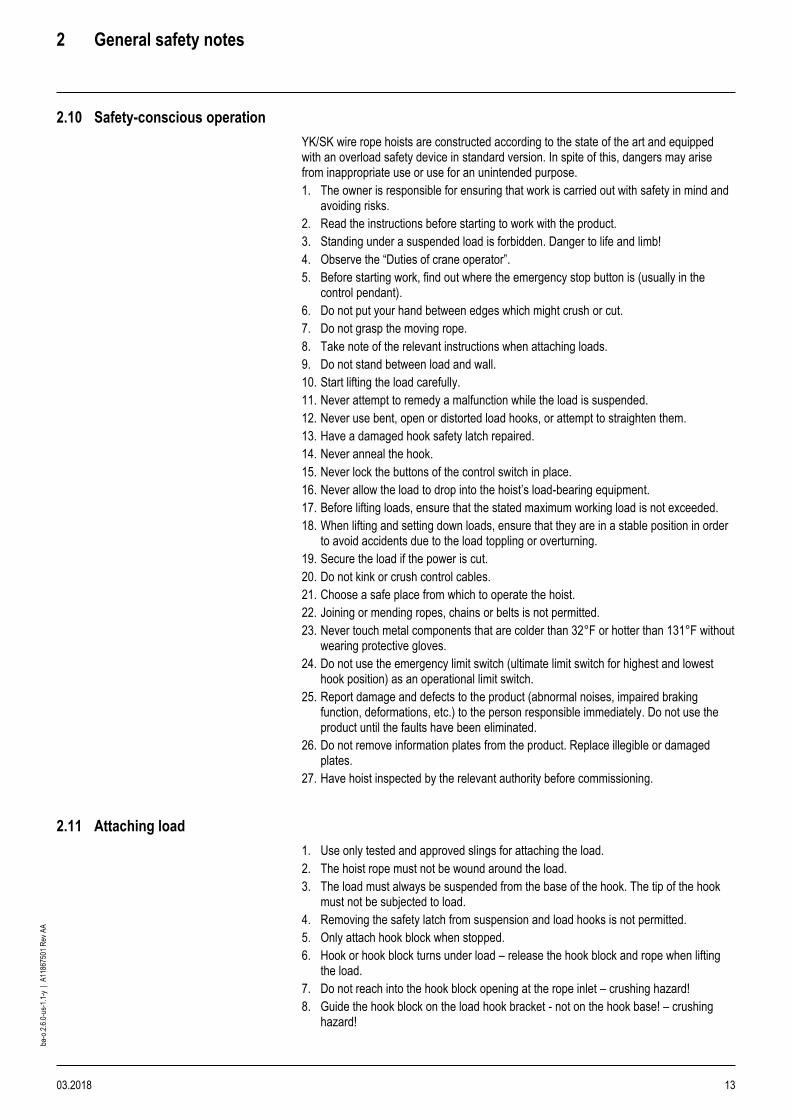
2.10 Safety-conscious operation
YK/SK wire rope hoists are constructed according to the state of the art and equipped with an overload safety device in standard version. In spite of this, dangers may arise from inappropriate use or use for an unintended purpose.
1. The owner is responsible for ensuring that work is carried out with safety in mind and avoiding risks.
2. Read the instructions before starting to work with the product.
3. Standing under a suspended load is forbidden. Danger to life and limb!
4. Observe the “Duties of crane operator”.
5. Before starting work, find out where the emergency stop button is (usually in the control pendant).
6. Do not put your hand between edges which might crush or cut.
7. Do not grasp the moving rope.
8. Take note of the relevant instructions when attaching loads.
9. Do not stand between load and wall.
10. Start lifting the load carefully.
11. Never attempt to remedy a malfunction while the load is suspended.
12. Never use bent, open or distorted load hooks, or attempt to straighten them.
13. Have a damaged hook safety latch repaired.
14. Never anneal the hook.
15. Never lock the buttons of the control switch in place.
16. Never allow the load to drop into the hoist’s load-bearing equipment.
17. Before lifting loads, ensure that the stated maximum working load is not exceeded.
18. When lifting and setting down loads, ensure that they are in a stable position in order to avoid accidents due to the load toppling or overturning.
19. Secure the load if the power is cut.
20. Do not kink or crush control cables.
21. Choose a safe place from which to operate the hoist.
22. Joining or mending ropes, chains or belts is not permitted.
23. Never touch metal components that are colder than 32°F or hotter than 131°F without wearing protective gloves.
24. Do not use the emergency limit switch (ultimate limit switch for highest and lowest hook position) as an operational limit switch.
25. Report damage and defects to the product (abnormal noises, impaired braking function, deformations, etc.) to the person responsible immediately. Do not use the product until the faults have been eliminated.
26. Do not remove information plates from the product. Replace illegible or damaged plates.
27. Have hoist inspected by the relevant authority before commissioning.
2.11 Attaching load
1. Use only tested and approved slings for attaching the load.
2. The hoist rope must not be wound around the load.
3. The load must always be suspended from the base of the hook. The tip of the hook must not be subjected to load.
4. Removing the safety latch from suspension and load hooks is not permitted.
5. Only attach hook block when stopped.
6. Hook or hook block turns under load – release the hook block and rope when lifting the load.
7. Do not reach into the hook block opening at the rope inlet – crushing hazard!
8. Guide the hook block on the load hook bracket - not on the hook base! – crushing hazard!

3 Introduction
14 03.2018
ba-o
.2.6
.0-u
s-1.
1-y
| A
1186
7501
Rev
AA
3 Introduction
Wire rope hoists are intended for lifting freely movable loads. The modular concept of our series of wire rope hoists permits a multitude of variations on the basis of series components. The design is characterized by the rope drum and hoist motor being arranged in parallel. The hoist drive is a cylindrical rotor motor with a separately activated D.C. brake. Its design complies with the FEM calculation regulations which are adapted to the requirements of hoist operation. The main components of the wire rope hoist are the hoist motor, the gear, the rope drum and the control box with connection parts. Our certified quality assurance system to DIN ISO 9001 guarantees consistently high quality.
14
15
16
17
18
Fig. 5
1 Panel box with connection parts 2 Emergency hoist limit switch, operational hoist limit switch
3 Gear 4 Mounting point for safety brake (YKB/SKB – YKE/SKE)
5 Rope drum 6 Rope guide with rope tensioning spring
7 Clamps for rope attachment 8 Rope drum bearing
9 End cover 10 Motor
11 Brake 12 Fan
13 Fan cover 14 Stationary wire rope hoist, hoist for incorporation
15 Wire rope hoist with “short headroom” monorail trolley 16 Wire rope hoist with “standard headroom” monorail trolley
17 Wire rope hoist with “articulated” monorail trolley 18 Wire rope hoist with double rail trolley

3 Introduction
03.2018 15
ba-o
.2.6
.0-u
s-1.
1-y
| A
1186
7501
Rev
AA
3.1 Incorporation
Stationary hoist (hoist for incorporation) The hoist is connected to a fixed structure by means of bolt joints permitting it to be attached to a base, wall or ceiling. Mobile hoist The hoists can be mounted on 4 different types of travel carriage.

4 Installation
16 03.2018
ba-o
.2.6
.0-u
s-1.
1-y
| A
1186
7501
Rev
AA
4 Installation
4.1 Stationary hoist
Fig. 6
Wire rope
hoist type
MT (rope drum torque)
[lbf in]
YKA/SKA ½ × F × 5 in
YKB/SKB ½ × F × 6.6 in
YKC/SKC ½ × F × 8.6 in
YKE/SKE ½ × F × 14 in
Possible mounting positions and fleet angles Feet “at bottom” and “at top” are possible for designs with bottom hook block (rope lead-off vertically downwards). The YK/SK wire rope hoist with 1PS and 1PS twin hook rope lead-off can be installed in various positions (fleet angles see page 20-23, section 4.2 “Fleet angle”) 1. If possible, install the hoist in the preferred installation position ***
(see page 20, section 4.2 1 “Attachment at bottom”)
2. Use the fixing elements specified, see the following figures and tables.
3. Take care that no distortion arises from unevenness (max. 0.5°, max. 0.079 in.)
4. The customer's substructure must take up the torque MT from the rope drum. It must therefore be torsion resistant.
5. If the rope lead-off is not vertical, the shearing forces arising must be taken up by a shear bar.
6. For tightening torques see page 102, section 11.4 “Tightening torques”.
Standard reevings
1PS 2PS 4PS 1PD 2PD 4PD
Fig. 7

4 Installation
03.2018 17
ba-o
.2.6
.0-u
s-1.
1-y
| A
1186
7501
Rev
AA
4.1.1 Attachment at bottom
Type YKA/SKA pcs
(1) Screw M16-8.8 6
(2) SCHNORR® Safety Washer S16 12
(3) Nut, M16-8 6
Type YKB/SKB pcs
(1) Screw M20-8.8 6
(2) SCHNORR® Safety Washer S20 12
(3) Nut, M20-8 6
Type YKC/SKC pcs
(1) Nut, M24-8 6
(2) SCHNORR® Safety Washer S24 12
(3) Screw M24-8.8 6
Type YKE/SKE, YKD/SKD (2PS, 4PS, 2PD) pcs
(1) Screw M30-8.8 8
(2) SCHNORR® Safety Washer S24 16
(3) Nut, M30-8 8

4 Installation
18 03.2018
ba-o
.2.6
.0-u
s-1.
1-y
| A
1186
7501
Rev
AA
Type YKE/SKE (1PS) pcs
(1) Nut, M24-8 8
(2) SCHNORR® Safety Washer S24 16
(3) Screw M24-8.8 8
Fig. 8
4 Installation
03.2018 19
ba-o
.2.6
.0-u
s-1.
1-y
| A
1186
7501
Rev
AA
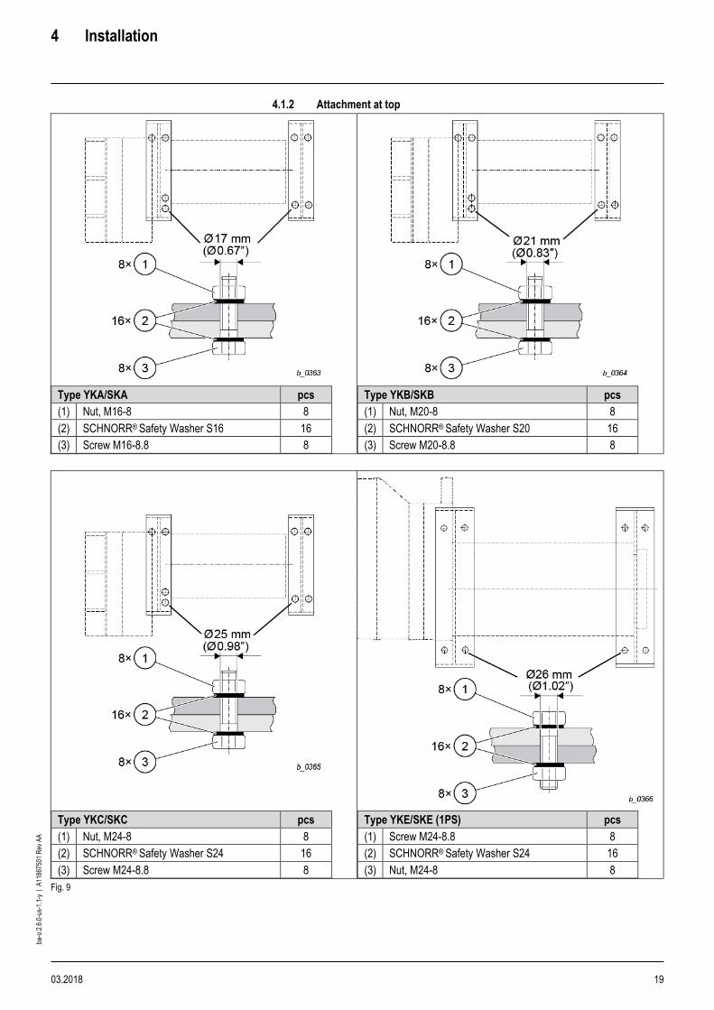
4.1.2 Attachment at top
Type YKA/SKA pcs
(1) Nut, M16-8 8
(2) SCHNORR® Safety Washer S16 16
(3) Screw M16-8.8 8
Type YKB/SKB pcs
(1) Nut, M20-8 8
(2) SCHNORR® Safety Washer S20 16
(3) Screw M20-8.8 8
Type YKC/SKC pcs
(1) Nut, M24-8 8
(2) SCHNORR® Safety Washer S24 16
(3) Screw M24-8.8 8
Type YKE/SKE (1PS) pcs
(1) Screw M24-8.8 8
(2) SCHNORR® Safety Washer S24 16
(3) Nut, M24-8 8
Fig. 9

4 Installation
20 03.2018
ba-o
.2.6
.0-u
s-1.
1-y
| A
1186
7501
Rev
AA
4.2 Fleet angle
4.2.1 Attachment at bottom
Wire rope hoist types YKA/SKA, YKB/SKB, YKC/SKC, YKE/SKE
1PS,
1PS twin hook
YKA/ SKA
YKB/ SKB
YKC/
SKC
YKE/ SKE
α1 4° 5° 8° 8°
α2 23° 13° 20° 18°
α3 27° 30° 30° 30°
α4 74° 73° 76° 80°
α5 30° 30° 30° 25°
α6 113° 103° 110° 108°
α7 63° 61° 60° 60°
α8 11° 12° 16° 20°
α9 24° 26° 30° -
α10 7° 7° 8° 8°
α12 90° 90° 90° - Tab. 3
Fig. 10
*** Preferred installation position 1) Standard 2) By turning rope guide 4) By turning rope guide and grease pan.
Type YKE/SKE: Version (G) not possible

4 Installation
03.2018 21
ba-o
.2.6
.0-u
s-1.
1-y
| A
1186
7501
Rev
AA
4.2.2 Attachment at top
Wire rope hoist types YKA/SKA, YKB/SKB, YKC/SKC, YKE/SKE
1PS,
1PS twin hook
YKA/
SKA
YKB/
SKB
YKC/ SKC
YKE/ SKE
α1 4° 5° 8°
on request
α2 23° 13° 20°
α3 27° 30° 30°
α4 74° 73° 76°
α5 16° 17° 14°
α6 35° 32° 36°
α7 74° 74° 76°
α12 90° 90° 90°
α13 90° 90° 90° Tab. 4
Fig. 11
1) Standard
2) By turning rope guide
4) By turning rope guide and grease pan.
Type YKE/SKE: Version (H) not possible

4 Installation
22 03.2018
ba-o
.2.6
.0-u
s-1.
1-y
| A
1186
7501
Rev
AA
4.2.3 Attachment at side
Wire rope hoist types YKA/SKA, YKB/SKB, YKC/SKC, YKE/SKE
1PS,
1PS twin hook
YKA/ SKA
YKB/ SKB
YKC/ SKC
YKE/ SKE
α1 21° 23° 18°
on request
α2 12° 13° 20°
α3 74° 73° 76°
α4 10° 10° 20°
α5 21° 23° 18°
α6 23° 20° 20°
α7 27° 30° 30°
α8 74° 73° 76°
α9 4° 5° 8°
α10 23° 13° 20°
α11 27° 30° 30°
α12 74° 73° 76°
α13 - - 70°
α14 - - 6°
Tab. 5
Fig. 12
2) By turning rope guide
4) By turning rope guide and grease pan.
Type YKE/SKE: Version (H) not possible
4 Installation
03.2018 23
ba-o
.2.6
.0-u
s-1.
1-y
| A
1186
7501
Rev
AA
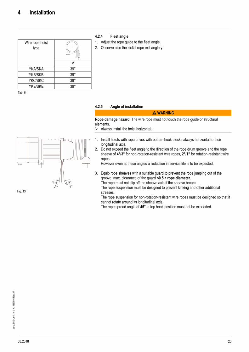
4.2.4 Fleet angle
Wire rope hoist
type
γ
YKA/SKA 39°
YKB/SKB 39°
YKC/SKC 39°
YKE/SKE 39°
Tab. 6
1. Adjust the rope guide to the fleet angle.
2. Observe also the radial rope exit angle γ.
4.2.5 Angle of installation
WARNING
Rope damage hazard. The wire rope must not touch the rope guide or structural elements. ➢ Always install the hoist horizontal.
Fig. 13
1. Install hoists with rope drives with bottom hook blocks always horizontal to their longitudinal axis.
2. Do not exceed the fleet angle to the direction of the rope drum groove and the rope sheave of 4°/3° for non-rotation-resistant wire ropes, 2°/1° for rotation-resistant wire ropes. However even at these angles a reduction in service life is to be expected.
3. Equip rope sheaves with a suitable guard to prevent the rope jumping out of the groove, max. clearance of the guard <0.5 × rope diameter. The rope must not slip off the sheave axle if the sheave breaks. The rope suspension must be designed to prevent kinking and other additional stresses. The rope suspension for non-rotation-resistant wire ropes must be designed so that it cannot rotate around its longitudinal axis. The rope spread angle of 45° in top hook position must not be exceeded.
4 Installation
24 03.2018
ba-o
.2.6
.0-u
s-1.
1-y
| A
1186
7501
Rev
AA
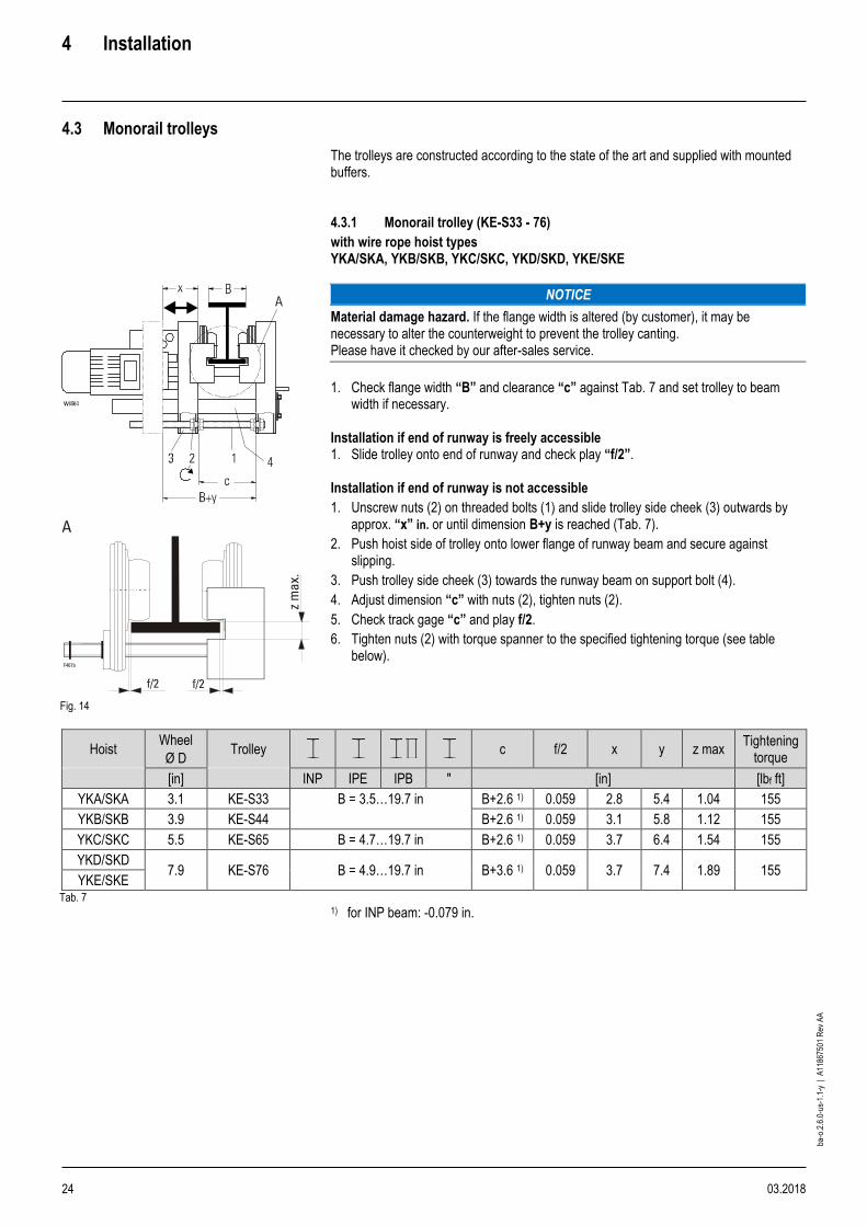
4.3 Monorail trolleys
The trolleys are constructed according to the state of the art and supplied with mounted buffers. 4.3.1 Monorail trolley (KE-S33 - 76)
with wire rope hoist types YKA/SKA, YKB/SKB, YKC/SKC, YKD/SKD, YKE/SKE
Fig. 14
NOTICE
Material damage hazard. If the flange width is altered (by customer), it may be necessary to alter the counterweight to prevent the trolley canting. Please have it checked by our after-sales service.
1. Check flange width “B” and clearance “c” against Tab. 7 and set trolley to beam
width if necessary. Installation if end of runway is freely accessible 1. Slide trolley onto end of runway and check play “f/2”. Installation if end of runway is not accessible
1. Unscrew nuts (2) on threaded bolts (1) and slide trolley side cheek (3) outwards by approx. “x” in. or until dimension B+y is reached (Tab. 7).
2. Push hoist side of trolley onto lower flange of runway beam and secure against slipping.
3. Push trolley side cheek (3) towards the runway beam on support bolt (4).
4. Adjust dimension “c” with nuts (2), tighten nuts (2).
5. Check track gage “c” and play f/2.
6. Tighten nuts (2) with torque spanner to the specified tightening torque (see table below).
Hoist Wheel
Ø D Trolley c f/2 x y z max
Tightening torque
[in] INP IPE IPB " [in] [lbf ft]
YKA/SKA 3.1 KE-S33 B = 3.5…19.7 in B+2.6 1) 0.059 2.8 5.4 1.04 155
YKB/SKB 3.9 KE-S44 B+2.6 1) 0.059 3.1 5.8 1.12 155
YKC/SKC 5.5 KE-S65 B = 4.7…19.7 in B+2.6 1) 0.059 3.7 6.4 1.54 155
YKD/SKD 7.9 KE-S76 B = 4.9…19.7 in B+3.6 1) 0.059 3.7 7.4 1.89 155
YKE/SKE Tab. 7
1) for INP beam: -0.079 in.

4 Installation
03.2018 25
ba-o
.2.6
.0-u
s-1.
1-y
| A
1186
7501
Rev
AA
4.3.2 Drive shaft for travel drive (trolleys KE-S33 - KE-S65)
Drive shaft
Ø D B L Position
[in] [in] [in]
3.1 3.9
SF17 1.. SF17 2..
3.5 - 5.7 15.4 X3 -
5.7 - 7.7 - X4
7.7 - 9.8 19.5 X3 -
9.9 - 12 - X4
12.1 - 13.8 23.4 X3 -
13.8 - 15.7 - X4
15.8 - 17.7 27.4 X3 -
17.8 - 19.7 - X4
5.5
SF17 2..
4.7 - 7.9 19.9 X3 -
7.9 - 12.2 - X4
12.2 - 15.7 27.4 X3 -
15.8 - 19.7 - X4
7.9
SF17 2..
4.9 - 8.7 20.1 see next page 8.7 - 15.7 29.1
15.8 - 19.7 30.7 Tab. 8
Fig. 15
Ø D L3 ±0.079 L4 ±0.079
[in] [in] [in]
3.1 3.8 1.83
3.9
5.5 4.91 1.83
Tab. 9
1. Fit drive shaft in mounting position X3 or X4 depending on flange width (B) of runway
beam and length (L) of drive shaft (D).
2. Fit circlips (S).

4 Installation
26 03.2018
ba-o
.2.6
.0-u
s-1.
1-y
| A
1186
7501
Rev
AA
4.3.3 Drive shaft for trolley drive (trolley KE-S76)
The drive shaft is suitable for girder flange widths “B” from 4.9 in. to 19.7 in.
Fig. 16
Wire rope hoist type
Wheel
Ø D
Trolley Travel drive L d f/2 Tightening torque
[in] INP IPE IPB " [in] [in] [lbf ft]
YKD/SKD
YKE/SKE 7.9 KE-S76
SF17 2.. B = 4.9 - 8.7 in 20
B+3.6 1) 0.059 155 B = 8.7 - 15.7 in 29
B = 15.8 - 19.7 in 31
1) for INP beam: -0.079 in. 1. Insert drive shaft (5) into the two drive pinions (6) from the counterweight side, then
assemble spacer tube (7) and adjusting ring (8).
2. Adjust drive shaft (5) so that on the hoist side the shaft end projects by between min. 0 in. and max. 4.72 in. beyond the drive pinion (6) and on the counterweight side the shaft end projects by between min. 1.9 in. and max. 6.3 in. beyond the trolley side cheek (10).
3. Lock adjusting ring (8) with adjusting screw so that on spacer tube (7) lying against drive pinion (6) there is a play of approx. 0.079 - 0.157 in. to adjusting ring (8).
4. After fitting travel drive, check drive shaft (5) for ease of movement.

4 Installation
03.2018 27
ba-o
.2.6
.0-u
s-1.
1-y
| A
1186
7501
Rev
AA
4.3.4 Monorail trolley (UE-S4)
with YKB/SKB, YKC/SKC, 1PS wire rope hoists (single fall)
Fig. 17
Ø D Trolley c f/2 x y
z max
Tightening torque
[in] INP IPE IPB " [in] [lbf ft]
3.9 UE-S4 B = 3.5…19.7 in B+2.6 1) 0.059 3 5.6 1.12 155
Tab. 10 1) for INP beam: -0.079 in. 1. Check flange width “B” and clearance c ±0.079 in. against Tab. 10 and set trolley to
beam width if necessary. Ensure that the connection piece (square tube) (6) is in the center (of dimension “c”) between the trolley side cheeks (z1 = z2).
2. After unscrewing nuts (3) together with nuts (2), adjust clearance c ±0.079 in. and tighten nuts (3).
3. Tighten nuts with torque spanner to the specified tightening torques (see table above).
4. Clearance “c” results in a flange play of f/2 +0.039 in. on each side. If necessary, correct flange play by means of clearance “c”.
Installation if end of runway is freely accessible 1. Slide trolley onto end of runway and check play f/2. Installation if end of runway is not accessible 1. Loosen nuts (3) on threaded bolts (1) in the square tube of the trolley side cheeks (4)
and unscrew by dimension “x”.
2. Push trolley side cheeks (4) apart in parallel up to the unscrewed nuts (3) until dimension B+y or c+x is reached.
3. Slide trolley onto the bottom flange of the runway beam on the axle keep plate side (8) and secure against shifting.
4. Push trolley side cheeks (4) back to nuts (2), retighten nuts (3).
5. Check track gage c ±0.079 in. and play of guide rollers f/2.
6. Tighten nuts with torque spanner to the specified tightening torques (see table above).

4 Installation
28 03.2018
ba-o
.2.6
.0-u
s-1.
1-y
| A
1186
7501
Rev
AA
Centering connection piece
1. Loosen nuts (5) and shift connection piece (6) on connecting bolt (7) so that dimensions “z1” and “z2” between trolley side cheeks (4) and connection piece (6) are equal on both sides.
2. Tighten nuts (5) with torque spanner to the specified tightening torques (see table above).
Connecting bolt and drive shaft
Drive shaft
Ø D B L Position
[in] [in] [in]
3.1 3.9
SF17 1.. SF17 2..
3.5 - 5.7 15.4 X3 -
5.7 - 7.7 - X4
7.7 - 9.8 19.5 X3 -
9.9 - 12 - X4
12.1 - 13.8 23.4 X3 -
13.8 - 15.7 - X4
15.8 - 17.7 27.4 X3 -
17.8 - 19.7 - X4
5.5
SF17 2..
4.7 - 7.9 19.9 X3 -
7.9 - 12.2 - X4
12.2 - 15.7 27.4 X3 -
15.8 - 19.7 - X4
7.9
SF17 2..
4.9 - 8.7 20.1 see next page 8.7 - 15.7 29.1
15.8 - 19.7 30.7
1. Use connecting bolt and drive shaft suitable for beam range “B”.
4 Installation
03.2018 29
ba-o
.2.6
.0-u
s-1.
1-y
| A
1186
7501
Rev
AA
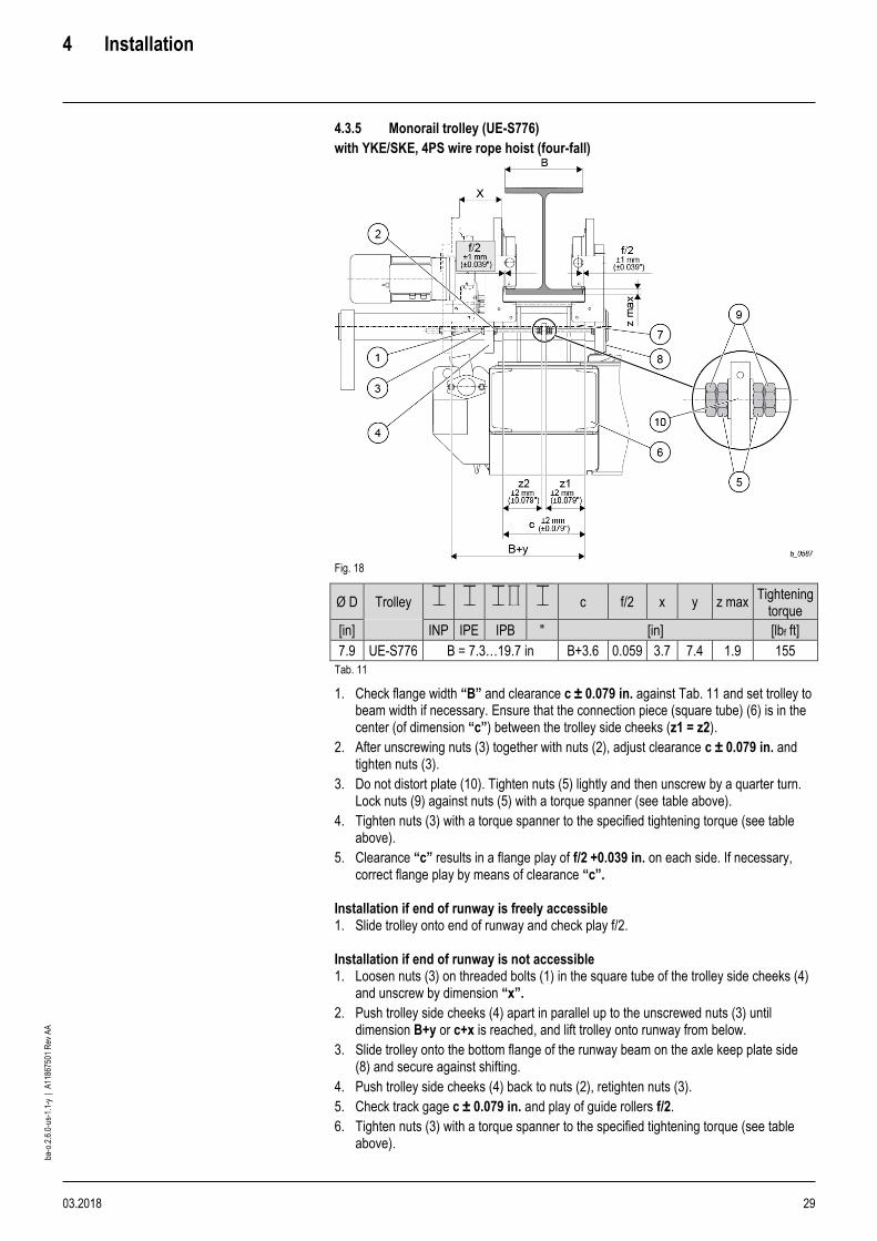
4.3.5 Monorail trolley (UE-S776)
with YKE/SKE, 4PS wire rope hoist (four-fall)
Fig. 18
Ø D Trolley c f/2 x y z max Tightening
torque
[in] INP IPE IPB " [in] [lbf ft]
7.9 UE-S776 B = 7.3…19.7 in B+3.6 0.059 3.7 7.4 1.9 155
Tab. 11
1. Check flange width “B” and clearance c ± 0.079 in. against Tab. 11 and set trolley to beam width if necessary. Ensure that the connection piece (square tube) (6) is in the center (of dimension “c”) between the trolley side cheeks (z1 = z2).
2. After unscrewing nuts (3) together with nuts (2), adjust clearance c ± 0.079 in. and tighten nuts (3).
3. Do not distort plate (10). Tighten nuts (5) lightly and then unscrew by a quarter turn. Lock nuts (9) against nuts (5) with a torque spanner (see table above).
4. Tighten nuts (3) with a torque spanner to the specified tightening torque (see table above).
5. Clearance “c” results in a flange play of f/2 +0.039 in. on each side. If necessary, correct flange play by means of clearance “c”.
Installation if end of runway is freely accessible 1. Slide trolley onto end of runway and check play f/2. Installation if end of runway is not accessible 1. Loosen nuts (3) on threaded bolts (1) in the square tube of the trolley side cheeks (4)
and unscrew by dimension “x”.
2. Push trolley side cheeks (4) apart in parallel up to the unscrewed nuts (3) until dimension B+y or c+x is reached, and lift trolley onto runway from below.
3. Slide trolley onto the bottom flange of the runway beam on the axle keep plate side (8) and secure against shifting.
4. Push trolley side cheeks (4) back to nuts (2), retighten nuts (3).
5. Check track gage c ± 0.079 in. and play of guide rollers f/2.
6. Tighten nuts (3) with a torque spanner to the specified tightening torque (see table above).

4 Installation
30 03.2018
ba-o
.2.6
.0-u
s-1.
1-y
| A
1186
7501
Rev
AA
Centering connection piece 1. Loosen nuts (5) and shift connection piece (6) on connecting bolt (7) so that
dimensions “z1” and “z2” between trolley side cheeks (4) and connection piece (6) are equal on both sides.
2. Tighten nuts (5) with a torque spanner to the specified tightening torque (see table above).
Connecting bolt and drive shaft 3. Use connecting bolt and drive shaft suitable for beam range “B” (for dimensions, see
Fig. 19). Drive shaft for trolley drive (trolley UE-S776)
Fig. 19
B L L1 L2 f/2
[in] [in] [in] [in] [in]
7.3 - 8.7 20.1 3.3 5.1 - 3.7
0.059 8.7 - 14.2 24.4 3.3 6.8 - 1.3
14.2 - 17.7 29.1 5.3 3.9 - 0.35
17.8 - 19.7 29.1 3.3 2.3 - 0.35
Tab. 12
The drive shaft is suitable for girder flange widths “B” from 7.3 in. to 19.7 in. (see Tab. 12 for length “L”). 1. Insert drive shaft (1) into the two drive pinions (6) from the counterweight side, then
assemble spacer tube (3) and adjusting ring (4).
2. Adjust drive shaft (1) to dimension “L1”, dimension “L2” must lie between the values given in the table.
3. Lock adjusting ring (4) with adjusting screw.
4. After fitting travel drive, check drive shaft (1) for ease of movement. The axial play must be approx. 2 – 4 mm (0.08 – 1.57 in.)
4 Installation
03.2018 31
ba-o
.2.6
.0-u
s-1.
1-y
| A
1186
7501
Rev
AA
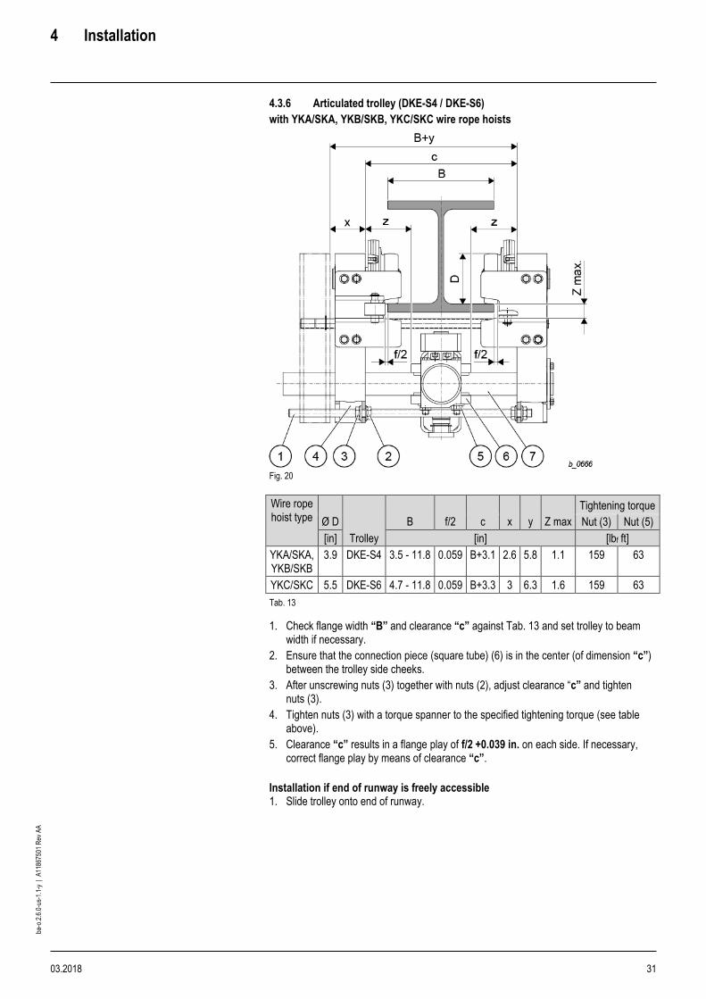
4.3.6 Articulated trolley (DKE-S4 / DKE-S6)
with YKA/SKA, YKB/SKB, YKC/SKC wire rope hoists
Fig. 20
Wire rope hoist type Ø D
Trolley
B f/2 c x y Z max
Tightening torque
Nut (3) Nut (5)
[in] [in] [lbf ft]
YKA/SKA, YKB/SKB
3.9 DKE-S4 3.5 - 11.8 0.059 B+3.1 2.6 5.8 1.1 159 63
YKC/SKC 5.5 DKE-S6 4.7 - 11.8 0.059 B+3.3 3 6.3 1.6 159 63
Tab. 13
1. Check flange width “B” and clearance “c” against Tab. 13 and set trolley to beam width if necessary.
2. Ensure that the connection piece (square tube) (6) is in the center (of dimension “c”) between the trolley side cheeks.
3. After unscrewing nuts (3) together with nuts (2), adjust clearance “c” and tighten nuts (3).
4. Tighten nuts (3) with a torque spanner to the specified tightening torque (see table above).
5. Clearance “c” results in a flange play of f/2 +0.039 in. on each side. If necessary, correct flange play by means of clearance “c”.
Installation if end of runway is freely accessible 1. Slide trolley onto end of runway.

4 Installation
32 03.2018
ba-o
.2.6
.0-u
s-1.
1-y
| A
1186
7501
Rev
AA
Installation if end of runway is not accessible
1. Loosen nuts (3) on threaded bolts (1) in the square tube of the trolley side cheeks (4) and unscrew by dimension “x”.
2. Push trolley side cheeks (4) apart in parallel up to the unscrewed nuts (3) until dimension B+y or c+x is reached, and lift trolley onto runway from below.
3. Lift trolley onto runway from below.
4. Slide trolley onto the bottom flange of the runway beam on the hoist side and secure against shifting.
5. Push trolley side cheeks (4) back to nuts (2), retighten nuts (3).
6. Check track gage “c” and play of guide rollers f/2.
7. Tighten nuts (3) with a torque spanner to the specified tightening torque (see table above).
Centering bogie
1. Loosen nuts (5) and shift bogie (6) on connecting bolt (7).
2. Dimension “z” between trolley side cheeks (4) and bogie (6) is equal on both sides.
3. Tighten nuts (5) with a torque spanner to the specified tightening torque (see table above).

4 Installation
03.2018 33
ba-o
.2.6
.0-u
s-1.
1-y
| A
1186
7501
Rev
AA
Drive shaft for travel drive (DKE-S4 / DKE-S6) Trolleys with one travel drive
Fig. 21
Drive shaft D
Ø D B L L4 ±0.079
[in] [in] [in] [in]
3.9 3.5 - 5 15.4
1.83 5.1 - 8.7 19.5
5.5 4.7 - 11 19.5
11.1 - 11.8 28 Tab. 14 The drive shaft “D” is suitable for beam widths “B” from 3.5 in. to 11.8 in. 1. Fit lock washers “S” acc. to dimension “L4”.
The mounting position of the drive shaft does not change over the corresponding beam range “B”.
Trolleys with two travel drives
Ø D 3.9 in
Ø D 5.5 in
Fig. 22
The drive shaft is completely independent of the beam width.
1. Mount lock washers “S” acc. To Fig.21 and Fig. 22. Drawings above

4 Installation
34 03.2018
ba-o
.2.6
.0-u
s-1.
1-y
| A
1186
7501
Rev
AA
4.4 End stops for monorail trolleys
WARNING
Falling parts hazard. If there are no end stops, the trolley can travel over the end of the runway.
➢ Mount suitable end stops at the end of the runway before commissioning the hoist.
The monorail trolleys are supplied as standard with buffers. Suitable runway end stops, to be clamped onto the lower flange of the runway, can be supplied.
WARNING
Falling parts hazard. ➢ With inclined flanges use supplied special screws.
[mm] [in]
A 112 4.41
B 134 5.28
C 56 2.2
D ≥ 15 ≥ 0.59
E 70 2.76
F 63 2.48
G 33 1.3
H see table below see table below
J 7 - 35 0.28 - 1.38
K 25 - 40 0.98 - 1.57
L 70 2.76
M 40 1.57
N 94 3.7
P 134 5.28
Q ≥ 15 ≥ 0.59
R 56 2.2
S 105 4.13
T 190 7.48
Fig. 23
Type 1) b max. Weight Trolley E max. Max. buffer force Order No.
[in] [lb] Type max. [ton] [lbf ft] [lbf]
PA1/300 ≤11.8 13 ≤YKD/SKD, 4PS
(≤KE-S76)
17.6 207 9663 01 740 57 27 0
PA1/500 11.8-19.7 14 01 740 58 27 0
PA1/1000 19.7-39.4 14 01 740 64 27 0
PA2/500 ≤19.7 31 ≤YKE/SKE, 4PS
(≤UE-S77)
35.3 251 8989 01 740 59 27 0
PA2/1000 >19.7-39.4 32 01 740 65 27 0
PA1/300 ≤11.8 13 ≤YKD/SKE, 4PS
(≤KE-S76)
17.6 207 9663 01 740 57 27 0
01 740 00 92 0 2)
Tab. 15
1) Limit switches necessary for travel speeds
> 105 fpm (PA1) > 82 fpm (PA2)
2) Special screw (must also be ordered)
4 Installation
03.2018 35
ba-o
.2.6
.0-u
s-1.
1-y
| A
1186
7501
Rev
AA
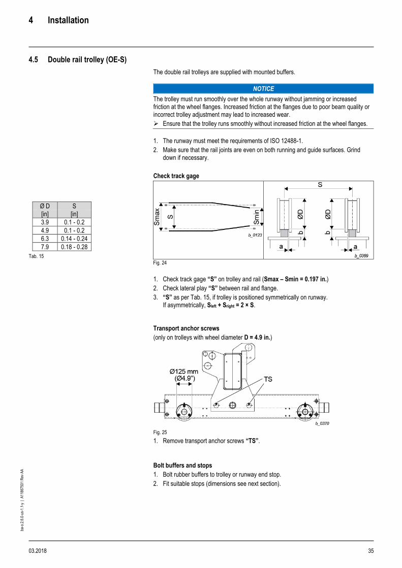
4.5 Double rail trolley (OE-S)
The double rail trolleys are supplied with mounted buffers.
NOTICE
The trolley must run smoothly over the whole runway without jamming or increased friction at the wheel flanges. Increased friction at the flanges due to poor beam quality or incorrect trolley adjustment may lead to increased wear.
➢ Ensure that the trolley runs smoothly without increased friction at the wheel flanges.
1. The runway must meet the requirements of ISO 12488-1.
2. Make sure that the rail joints are even on both running and guide surfaces. Grind down if necessary.
Check track gage
Ø D S
[in] [in]
3.9 0.1 - 0.2
4.9 0.1 - 0.2
6.3 0.14 - 0.24
7.9 0.18 - 0.28
Tab. 15
Fig. 24
1. Check track gage “S” on trolley and rail (Smax – Smin = 0.197 in.)
2. Check lateral play “S” between rail and flange.
3. “S” as per Tab. 15, if trolley is positioned symmetrically on runway. If asymmetrically, Sleft + Sright = 2 × S.
Transport anchor screws
(only on trolleys with wheel diameter D = 4.9 in.)
Fig. 25
1. Remove transport anchor screws “TS”.
Bolt buffers and stops
1. Bolt rubber buffers to trolley or runway end stop.
2. Fit suitable stops (dimensions see next section).
4 Installation
36 03.2018
ba-o
.2.6
.0-u
s-1.
1-y
| A
1186
7501
Rev
AA
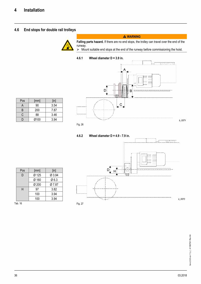
4.6 End stops for double rail trolleys
WARNING
Falling parts hazard. If there are no end stops, the trolley can travel over the end of the runway. ➢ Mount suitable end stops at the end of the runway before commissioning the hoist.
4.6.1 Wheel diameter D = 3.9 in.
Pos [mm] [in]
A 90 3.54
B 200 7.87
C 88 3.46
D Ø100 3.94
Fig. 26
4.6.2 Wheel diameter D = 4.9 - 7.9 in.
Pos [mm] [in]
D Ø 125 Ø 3.94
Ø 160 Ø 6.3
Ø 200 Ø 7.87
H 97 3.82
100 3.94
100 3.94
Tab. 16 Fig. 27
4 Installation
03.2018 37
ba-o
.2.6
.0-u
s-1.
1-y
| A
1186
7501
Rev
AA
4.7 Anti-jump catch
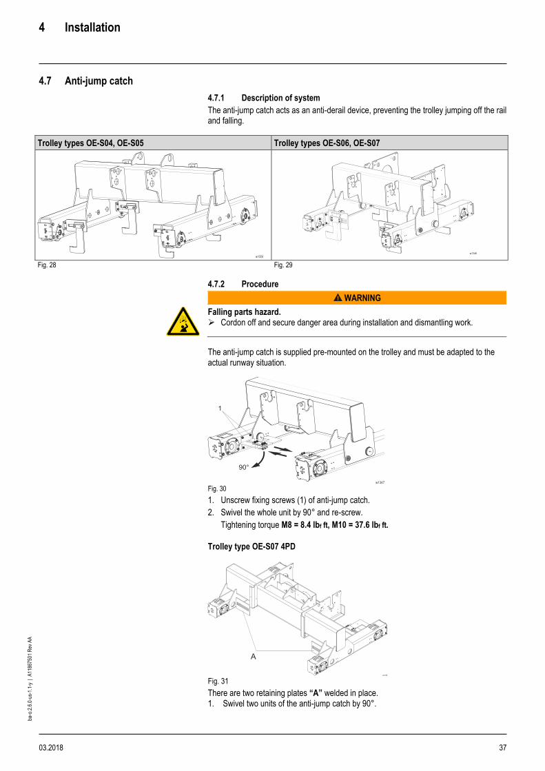
4.7.1 Description of system
The anti-jump catch acts as an anti-derail device, preventing the trolley jumping off the rail and falling.
Trolley types OE-S04, OE-S05 Trolley types OE-S06, OE-S07
Fig. 28 Fig. 29
4.7.2 Procedure
WARNING
Falling parts hazard. ➢ Cordon off and secure danger area during installation and dismantling work.
The anti-jump catch is supplied pre-mounted on the trolley and must be adapted to the actual runway situation.
Fig. 30
1. Unscrew fixing screws (1) of anti-jump catch.
2. Swivel the whole unit by 90° and re-screw.
Tightening torque M8 = 8.4 lbf ft, M10 = 37.6 lbf ft.
Trolley type OE-S07 4PD
Fig. 31
There are two retaining plates “A” welded in place. 1. Swivel two units of the anti-jump catch by 90°.

4 Installation
38 03.2018
ba-o
.2.6
.0-u
s-1.
1-y
| A
1186
7501
Rev
AA
Vertical adjustment
Fig. 32 1. Measure dimension “X”.
2. Select positions of hook and eccentric from the table.
Trolley type OE-S04 Trolley type OE-S04 Trolley type OE-S05
Hook position Eccentric position X Hook
position
Eccentric
[in]
1.65 - 1.77 1 B
1.79 - 1.89 C
1.91 - 2.05 2 A
2.07 - 2.17 B
2.19 - 2.28 C
2.3 - 2.44 3 A
2.46 - 2.56 B
2.58 - 2.68 C
2.7 - 2.83 4 A
2.85 - 2.95 B
X Hook position
Eccentric
[in]
1.57 - 1.69 1 B
1.71 - 1.81 C
1.83 - 1.95 2 A
1.97 - 2.09 B
2.11 - 2.2 C
2.22 - 2.34 3 A
2.36 - 2.48 B
2.5 - 2.6 C
2.62 - 2.74 4 A
2.76 - 2.87 B
2.89 - 2.99 C
3.01 - 3.13 5 A
3.15 - 3.27 B
Fig. 33
Trolley type OE-S05
Fig. 34

4 Installation
03.2018 39
ba-o
.2.6
.0-u
s-1.
1-y
| A
1186
7501
Rev
AA
Trolley types OE-S06 - OE-S07
Hook position Eccentric position X
Hook
position Eccentric
[in]
1.5 - 1.59 1 A
1.61 - 1.79 C
1.81 - 1.99 2 A
2.01 - 2.19 C
2.2 - 2.38 3 A
2.4 - 2.58 C
2.6 - 2.78 4 A
2.8 - 2.97 C
2.99 - 3.17 5 A
3.19 - 3.37 C
3.39 - 3.56 6 A
3.58 - 3.76 C
Fig. 35
Fig. 36
Fig. 37 Fig. 38
1. Unscrew fixing elements (1) and (2).
2. OE-S07 4PD: The pieces of two units are supplied loose (please unscrew as required).
3. Remove hook (3)
4. OE-S04: Rotate hook by 180°.
5. Insert adjusting screws “S” in the hook position determined from the table.
6. Position eccentric plates (4) in slot as specified by the table.
7. Tighten fixing elements (1) and (2) finger-tight. Horizontal adjustment:
Fig. 39
Pos
OE-S04 -OE-S05 OE-S06 - OE-S07
[in] [in]
Z ≥0.39 ≥0.59
Y ≥1.18 ≥1.18
1. Adjust final hook position according to Fig. and table.
2. Tighten fixing elements (1) and (2) with tightening torque M10 = 38 lbf ft.
NOTICE
Malfunction hazard. In the event of a fault, e.g. trolley running into the runway end stops unchecked, broken rope, all elements of the anti-jump catch must be checked immediately for damage/faults and completely replaced if necessary. The functional reliability of the system must be ensured.
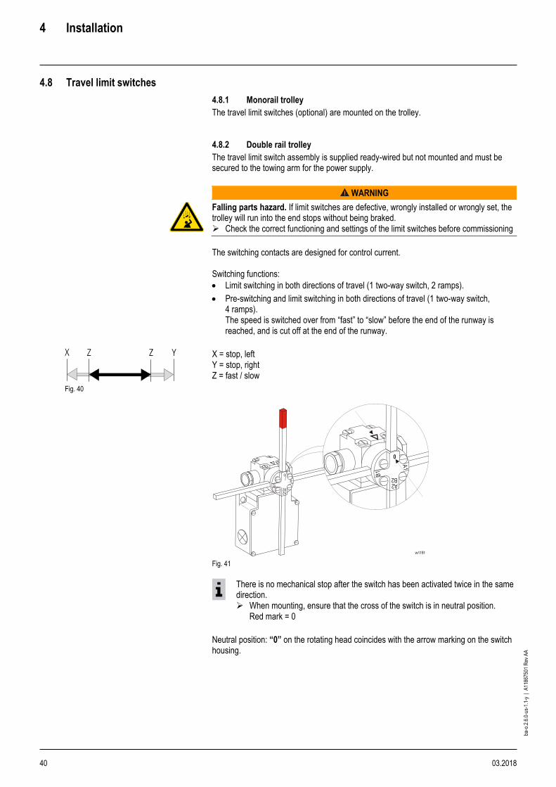
4 Installation
40 03.2018
ba-o
.2.6
.0-u
s-1.
1-y
| A
1186
7501
Rev
AA
4.8 Travel limit switches
4.8.1 Monorail trolley
The travel limit switches (optional) are mounted on the trolley. 4.8.2 Double rail trolley
The travel limit switch assembly is supplied ready-wired but not mounted and must be secured to the towing arm for the power supply.
WARNING
Falling parts hazard. If limit switches are defective, wrongly installed or wrongly set, the trolley will run into the end stops without being braked. ➢ Check the correct functioning and settings of the limit switches before commissioning
The switching contacts are designed for control current. Switching functions:
• Limit switching in both directions of travel (1 two-way switch, 2 ramps).
• Pre-switching and limit switching in both directions of travel (1 two-way switch, 4 ramps). The speed is switched over from “fast” to “slow” before the end of the runway is reached, and is cut off at the end of the runway.
Fig. 40
X = stop, left Y = stop, right Z = fast / slow
Fig. 41
There is no mechanical stop after the switch has been activated twice in the same direction. ➢ When mounting, ensure that the cross of the switch is in neutral position.
Red mark = 0
Neutral position: “0” on the rotating head coincides with the arrow marking on the switch housing.

4 Installation
03.2018 41
ba-o
.2.6
.0-u
s-1.
1-y
| A
1186
7501
Rev
AA
4.9 Electrical equipment
DANGER
Electric shock hazard
➢ Make sure an electrical qualified person performs the work.
➢ Observe the relevant safety and accident prevention regulations.
The electrical equipment of the hoist was designed, manufactured and tested in accordance with standard EN 60204-32. It comprises all electrical equipment of the hoist: Electrical equipment was installed per NFPA 70 or other National, State, and Local regulations.
• Energy supply (main isolator, conductor lines…)
• Energy distribution (transformers, crane disconnect switch, special circuits…)
• Operator interface and control devices mounted on the hoist (control pendant, radio transmitter, devices for emergency stop, limit switches…)
• Hoist control (electronic control devices, safety devices, radio receiver…)
• Drive, motor controls (power contactors, inverters…)
• Main drives (motors, brakes…)
• Auxiliary drives, sensors, load suspension equipment, actuators…)
4.9.1 Supply cables
Electrical service can be either power by cable or guarded system having sliding show contacts or wheel type collectors.
1. See section 11.3 for minimum cross-section and max. length of supply cable.
2. Select cables, leads and conductor lines to match the existing operating conditions (e.g. voltage, current, protection against electric shock, amassment of cables and leads) and for external influences (e.g. ambient temperature, presence of water or corrosive materials, mechanical stress).
4.9.2 Terminals
1. Check that all terminals are firm.

4 Installation
42 03.2018
ba-o
.2.6
.0-u
s-1.
1-y
| A
1186
7501
Rev
AA
4.9.3 Protection of equipment
Protective devices include:
• Devices for overcurrent protection (fuses, circuit breakers)
• Motor protection devices
• Overload safety devices
• Temperature monitors
• Limit switches
The protective devices in the electrical equipment installed in the scope of supply must in no case be removed, replaced by different devices or bridged. If a protective device has reacted, the hoist must not be put back in service until the cause has been determined and eliminated with the assistance of a qualified person. Overcurrent protection devices Every hoist must have devices for disconnecting and switching the power supply. This function is performed by the following devices: 4.9.4 Emergency stop
It must be possible to disconnect the system electrically from the operating position. This function can be provided by:
• Emergency stop button in the control pendant in conjunction with the crane switch contactor
• Main isolator.
4.9.5 Runway conductor disconnecting means
• must disconnect the wire rope hoist on all poles,
• must be lockable in OFF position,
• must be installed in an easily accessible place in the system,
• must be marked as such to avoid mistakes.
4.9.6 Disconnect switch
Required for one or more hoists,
• must be lockable in OFF position.
4.9.7 Connection fuses
• Overcurrent protection devices.
• The fuse values must be observed so that the crane switch contacts do not weld if there is a short circuit and overload protection of lead is ensured.

4 Installation
03.2018 43
ba-o
.2.6
.0-u
s-1.
1-y
| A
1186
7501
Rev
AA
4.9.8 Electromagnetic compatibility
Electromagnetic compatibility (EMC) mainly concerns the emission of electromagnetic interference and the immunity of electronic components and systems to this interference. If the following interference suppression measures are correctly installed and applied, the equipment will not cause any electromagnetic interference above the level permissible for the intended operating environment and have sufficient resistance to electromagnetic interference to function without error. Detailed information on EMC-compliant installation is given in a separate instruction manual. The system builder is responsible for the EMC of the system as a whole. In general, the product is designed for the operating environment “industrial environment”, or “2nd environment” in the case of use of frequency-controlled drives. The electronic control devices of the overload protection and any frequency inverters installed are interference-suppressed. You will find further information in the relevant operating instructions of the devices. The contacts of power contactors and rectifiers for motor brakes may generate interference exceeding the permissible values depending on output, cable length and other system parameters. Ready-to-connect electric wire rope hoists with declaration of conformity complying with machinery and EMC directives are interference-suppressed for the above operating environment. No particular protective measures have been taken on electric wire rope hoists with control by customer or crane builder's control. Appropriate precautions must be taken by the customer in order to comply with EMC standards with regard to interference values. In order to achieve an optimum result with minimum outlay, we recommend using our radio interference suppression module FEM1 for the YK/SK wire rope hoist.
• Order no. 578 525 0 ≤ 415 V
• Order no. 578 526 0 ≤ 800 V
Clip the module onto the top-hat rail and connect it to the mains supply cable.
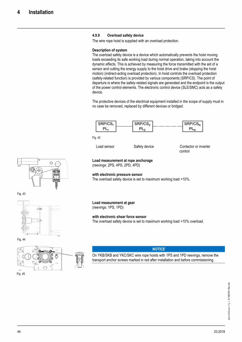
4 Installation
44 03.2018
ba-o
.2.6
.0-u
s-1.
1-y
| A
1186
7501
Rev
AA
4.9.9 Overload safety device
The wire rope hoist is supplied with an overload protection. Description of system The overload safety device is a device which automatically prevents the hoist moving loads exceeding its safe working load during normal operation, taking into account the dynamic effects. This is achieved by measuring the force transmitted with the aid of a sensor and cutting the energy supply to the hoist drive and brake (stopping the hoist motion) (indirect-acting overload protection). In hoist controls the overload protection (safety-related function) is provided by various components (SRP/CS). The point of departure is where the safety-related signals are generated and the endpoint is the output of the power control elements. The electronic control device (SLE/SMC) acts as a safety device. The protective devices of the electrical equipment installed in the scope of supply must in no case be removed, replaced by different devices or bridged.
Fig. 42
Load sensor Safety device Contactor or inverter control
Fig. 43
Load measurement at rope anchorage (reevings: 2PS, 4PS, 2PD, 4PD) with electronic pressure sensor The overload safety device is set to maximum working load +10%.
Fig. 44
Load measurement at gear (reevings: 1PS, 1PD) with electronic shear force sensor The overload safety device is set to maximum working load +10% overload.
Fig. 45
NOTICE
On YKB/SKB and YKC/SKC wire rope hoists with 1PS and 1PD reevings, remove the transport anchor screws marked in red after installation and before commissioning.
W0788

4 Installation
03.2018 45
ba-o
.2.6
.0-u
s-1.
1-y
| A
1186
7501
Rev
AA
Overload safety device by others
When an overload safety device and thus the placement of the load sensors to measure the rope forces are designed by others, all requirements relating to rope reeving, fleet angle and angle of installation of the hoist must be observed, see chap. 4.2 The overload safety device must be set during commissioning, see supplementary operating instructions. The declaration of conformity/declaration of incorporation only apply to the manufacturer's scope of delivery. The overload safety device cannot be set by the manufacturer if it is provided by others. 4.9.10 Connecting to mains
WARNING
Safety hazard. If this procedure is not observed, serious accidents or damage to the hoist may occur!
1. Compare existing mains voltage and frequency with the information on the rating
plate.
2. Route cables into the hoist connection box through the cable glands.
3. Connect according to the circuit diagrams supplied.
4. Measure control voltage. If the measured value exceeds the rated control voltage by more than 10%, a different tapping point must be selected on the primary side of the control transformer.
5. Do not connect any live lead to the temperature sensors! Damaged temperature sensors cannot protect the motor.
WARNING
On three phase hoists, it is possible to have “Reverse Phasing” causing the block to lower when the "UP" button is depressed. When this condition exists, the hoist operation will be dangerous.
6. Check that the direction of rotation of the rope drum corresponds to the symbols on
the control pendant: Activate “slow up” button on control pendant. Never activate “down” button first! If the hook moves upwards or does not move because the hoist limit switch has disconnected in top hook position, the phase connection is correct.
7. Crosscheck by activating “slow down” button on control pendant.
8. If the movement of the hook does not correspond to the symbols on the control pendant, interchange two phase conductors of the supply cable.

4 Installation
46 03.2018
ba-o
.2.6
.0-u
s-1.
1-y
| A
1186
7501
Rev
AA
4.9.11 Control and control functions
Each hoist control is equipped with an electronic control device. This electronic control device functions as a central safety device for the overload safety device and as motor control and monitoring unit. The device functions are adapted to the different hoist and drive types and the particular function modules selected (load limits, pole-changing or frequency-controlled motors, etc.) by parameterising the device. Two variants are used for this electronic control pendant: Variant 1
• SLE load monitor
• Standard control
• Parameterized with HEX and DIP switches Variant 2
• SMC multi-controller
• Extended functions - optional device
• Parameterized with config-tool and RS232 data interface or a USB interface
The following safety functions are integrated into the electronic control devices:
• Overload safety device
• Crane test possible with the aid of test button
• Protection against unexpected start-up
• Control of hoist motors with motor management
In addition, the devices perform the following non-safety-relevant control functions:
• Recording operating hours
• Temperature control for hoist and travel motors
• Display of system status
The general description of the control merely provides an outline. Detailed information on technical data, functions, integrating the control supplied into superordinate crane controls and troubleshooting are described in separate operating instructions for the electronic control devices and shown in the circuit diagrams. The same applies for frequency inverter controls. Controls by others
• If the unit is being supplied less controls. CMCO cannot guarantee hoist / motor performance utilizing controls not recommended or provided by CMCO.
• If the controls are supplied by others, connect the temperature sensors of the hoist and travel motors, the hoist brake, the overload safety device and the emergency hoist limit switch according to the connection diagrams.
• Do not connect any live lead to the temperature sensors! Damaged temperature sensors cannot protect the motor.
• When integrating the supplied control sections into an overall control, the product standards for hoists and technical specifications as regards functionality, signal sequence and timing of this control must be observed. The circuit diagrams and block circuit diagrams supplied as hoist documentation must be followed and implemented by the customer when constructing the control. The system builder is responsible for the system as a whole.
The declaration of conformity / declaration of incorporation are valid only for the scope supplied by the manufacturer.

4 Installation
03.2018 47
ba-o
.2.6
.0-u
s-1.
1-y
| A
1186
7501
Rev
AA
4.9.12 Electric motors and related equipment
The hoist motors meet the standards of EN 60034-1 and are specially dimensioned and designed for hoist operating conditions. Hoist motor
• 12/2-pole motor with separately controlled D.C. brake for contactor control
• The brake is designed as an operating brake
or
• 4-pole motor with separately controlled D.C. brake for frequency control
• The brake is designed as a holding brake and discharges the function of emergency stop
• Encoder with 600 pulses/rotation mounted on motor as standard (see encoder type plate and electrical switch diagrams).
Travel motor
• 8/2- pole motor with separately controlled D.C. brake for contactor control
• Integrated centrifugal mass for smooth acceleration and braking
or
• 4- pole motor with separately controlled D.C. brake for frequency control
The motors are equipped with closable condensation holes 1). All motors have ptc sensors integrated into the winding as thermal overload protection. Specification: Thermal class: F / H Utilization / insulation system Construction: IM B5 flange mounting on drive side Cooling: IC 411 surface cooling with integrated fan Standard operating conditions
• -4°F … +104°F
• Humidity up to 80%
• Air pressure up to 3280 ft above sea level
Options
• IP 66 1)
• Forced ventilation
• Space heating 1)
• Manual release for brake
1) Motors whose winding is subject to condensation due to climatic conditions, e.g. motors standing still in damp environments or motors exposed to high temperature fluctuations can be equipped with space heaters. They must also always be used in combination with type of protection IP 66 and high humidity.
4.10 YK/SK hoists with frequency inverter (VFD)
For information on the frequency inverter, see the separate instructions.

4 Installation
48 03.2018
ba-o
.2.6
.0-u
s-1.
1-y
| A
1186
7501
Rev
AA
4.11 Reeving rope
The wire rope is wound onto the drum in the factory. If not, see page 80, section 7.14.4 “Replacing wire rope”. The wire rope hoist must be switched on in order to reeve the rope. All work must therefore be carried out with extreme care: for your safety and for smooth functioning of the wire rope hoist! If the bottom hook block is not fitted, proceed as follows:
1. Gripper pliers hold the rope securely with a gripper pliers.
2. Lay out the end of the rope not wound on the drum, or let it hang freely.
3. Check that the wire rope lies snugly on the rope drum, tighten if necessary. If the fit is loose:
Dismount the rope guide, see page 79, section 7.14.3 “Removing rope guide” Tighten up the wire rope on the rope drum and tension. Mount the rope guide, see page 81, section 7.14.5 “Fitting rope guide”
NOTICE
Material damage hazard. Slack rope can destroy the rope guide and the wire rope.
Avoid slack rope on the drum.
Fig. 46
1. Color code the beginning of the rope on one side.
Reeve the end of the rope into the rope sheave(s) of the bottom hook block and return pulley(s) (see next page for details).
NOTICE
Material damage hazard to wire rope. Do not twist the rope, the color coding facilitates checking.
2. Fasten the end of the rope in the rope anchorage
3. Perform several runs over the full height of lift without load.
4. Repeat with increasing loads.
5. Make any twisting in the rope which may occur visible by sticking on a paper tag. Severe twisting is shown by the bottom hook block's turning, especially when not under load.
NOTICE
Material damage hazard. Twisted ropes compromise safety and damage the rope. If any twisting occurs, remove the wire rope and untwist by letting it hang freely or laying it out. Twisting in the wire rope prejudices safety and service life. Any twisting must therefore be removed before subjecting the hoist to any further load. The rope could otherwise be permanently distorted and might have to be replaced!
Reeving rope (YKA/SKA – YKE/SKE)
NOTICE
Reeve the rope as shown in the schematic drawings and attach the end of the rope at the rope anchorage. The bottom hook block must hang horizontally (./2-1)
The hook may rotate after a short time in operation due to residual stress in the rope

4 Installation
03.2018 49
ba-o
.2.6
.0-u
s-1.
1-y
| A
1186
7501
Rev
AA
YKA/SKA -YKC/SKC
YKE/SKE
1PS 1 1
2PS 2 4
4PS 3 5
1PD 6 6
2PD 7 8
4PD - 9
Tab. 17
YKA/SKA -YKC/SKC
YKE/SKE
2PS 4 4
4PS 5 5
2PD 8 8
Tab. 18
YKA/SKA -YKC/SKC
YKE/SKE
2PS 4 4
4PS 5 5
2PD 8 8
4PD - 9
Tab. 19
1
L
2
L
3
L
4 L
5 L
6 R L
7 R L
8 R L
9 R L
L = left-hand thread R = right-hand thread
Fig. 47
1PS 2PS 4PS
2PS 4PS
1PD 2PD 2PD
4PD
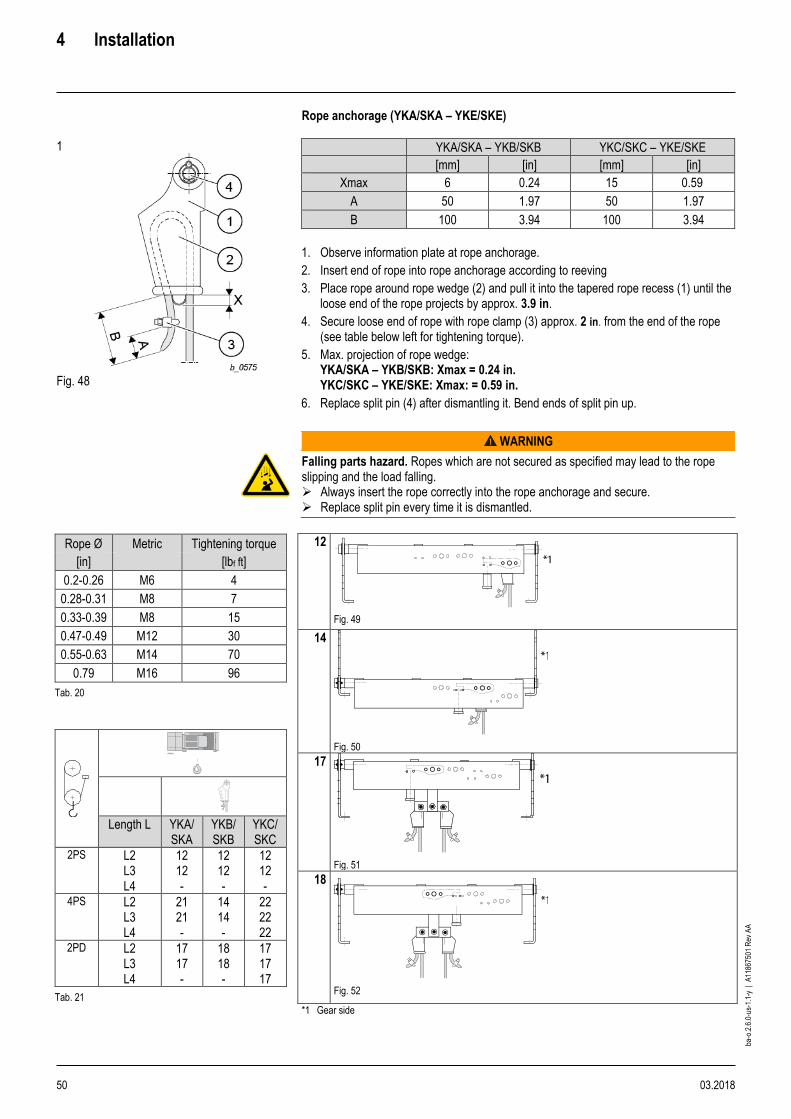
4 Installation
50 03.2018
ba-o
.2.6
.0-u
s-1.
1-y
| A
1186
7501
Rev
AA
Rope anchorage (YKA/SKA – YKE/SKE)
1
Fig. 48
YKA/SKA – YKB/SKB YKC/SKC – YKE/SKE
[mm] [in] [mm] [in]
Xmax 6 0.24 15 0.59
A 50 1.97 50 1.97
B 100 3.94 100 3.94
1. Observe information plate at rope anchorage.
2. Insert end of rope into rope anchorage according to reeving
3. Place rope around rope wedge (2) and pull it into the tapered rope recess (1) until the loose end of the rope projects by approx. 3.9 in.
4. Secure loose end of rope with rope clamp (3) approx. 2 in. from the end of the rope (see table below left for tightening torque).
5. Max. projection of rope wedge: YKA/SKA – YKB/SKB: Xmax = 0.24 in. YKC/SKC – YKE/SKE: Xmax: = 0.59 in.
6. Replace split pin (4) after dismantling it. Bend ends of split pin up.
WARNING
Falling parts hazard. Ropes which are not secured as specified may lead to the rope slipping and the load falling. ➢ Always insert the rope correctly into the rope anchorage and secure. ➢ Replace split pin every time it is dismantled.
Rope Ø Metric Tightening torque
[in] [lbf ft]
0.2-0.26 M6 4
0.28-0.31 M8 7
0.33-0.39 M8 15
0.47-0.49 M12 30
0.55-0.63 M14 70
0.79 M16 96
Tab. 20
Length L YKA/ SKA
YKB/ SKB
YKC/ SKC
2PS L2 L3 L4
12 12 -
12 12 -
12 12 -
4PS L2 L3 L4
21 21 -
14 14 -
22 22 22
2PD L2 L3 L4
17 17 -
18 18 -
17 17 17
Tab. 21
12
Fig. 49
14
Fig. 50
17
Fig. 51
18
Fig. 52
*1 Gear side

4 Installation
03.2018 51
ba-o
.2.6
.0-u
s-1.
1-y
| A
1186
7501
Rev
AA
Rope anchorage (YKA/SKA - YKC/SKC)
Length L YKA/ SKA
YKB/ SKB
YKC/ SKC
2PS L2 L3 L4
12 12 -
12 12 -
12 12 -
4PS L2 L3 L4
21 21 -
14 14 -
22 22 22
2PD L2 L3 L4
17 17 -
18 18 -
17 17 17
Tab. 22
Length L YKA/ SKA
YKB/ SKB
YKC/ SKC
2PS 24 24 24
4PS 23 23 23
2PD L2 L3 L4
25 26 -
25 26 -
25 26 26
Tab. 23
Length L YKA/ SKA
YKB/ SKB
YKC/ SKC
2PS 28 28 28
4PS 27 27 27
2PD L2 L3 L4
29 29 -
29 30 -
29 29 29
Tab. 24
21
Fig. 53
26
Fig. 54
22
Fig. 55
27
Fig. 56
a±0.12 b±0.12
[in] [in]
YKA 8.5 9.5
YKB 10.4 11.4
YKC 13.1 14.4
Tab. 25
23
Fig. 57
A ±0.12 b±0.12
[in] [in]
YKA 8.5 9.5
YKB 10.4 11.4
YKC 13.1 14.4
Tab. 26
28
Fig. 58
24
Fig. 59
29
Fig. 60
25
Fig. 61
30
Fig. 62
*1 Gear side

4 Installation
52 03.2018
ba-o
.2.6
.0-u
s-1.
1-y
| A
1186
7501
Rev
AA
Rope anchorage (YKE/SKE)
Length L YKE/SKE
2PS L2-L5 32
4PS L2-L5 31
1PD -
2PD L2-L5 34
4PD L3-L5 35
Tab. 27
Length L YKE/SKE
2PS L2-L5 32
4PS L2-L5 31
2PD L2-L5 34
Tab. 28
Length L YKE/SKE
2PS L2-L5 32
4PS L2-L5 31
2PD L2-L5 34
4PD L3-L5 35
Tab. 29
31
Fig. 63
32
Fig. 64
34
Fig. 65
35
Fig. 66
*1 Gear side
5 Commissioning
03.2018 53
ba-o
.2.6
.0-u
s-1.
1-y
| A
1186
7501
Rev
AA
5 Commissioning
The wire rope hoist has been subjected to a final inspection by the manufacturer in accordance with the EC Machinery Directive.
WARNING
Safety hazard.
➢ Make sure a qualified person performs commissioning.
When the hoist is commissioned and / or after a service call a comprehensive retest must always be performed. The following checks must be carried out:
1. That the wire rope hoist is completed with the original accessories as supplied (e.g. bottom hook block).
2. Tight fit of the rope on the drum.
3. If the fit is loose:
– Dismount the rope guide (see page 79, section 7.14.3 “Removing rope guide”). – Tighten up the wire rope on the rope drum and tension. – Mount the rope guide (see page 81, section 7.14.5 “Fitting rope guide”).
4. Correct selection and installation of all electrical equipment.
5. Connecting to mains (see page 45, section 4.9.10 “Connecting to mains”).
6. Rope reeving, rope twist, fleet angle and angle of installation of wire rope hoist (see page 48, section 4.11 “Reeving rope”).
7. The screw connections are tightened with the prescribed tightening torque.
8. Correct functioning of runway end stops.
WARNING
Safety hazard. On three phase hoists, it is possible to have “Reverse Phasing” causing the block to lower when the “UP” button is depressed. When this condition exists, the hoist operation will be dangerous.
9. The direction of motion of the load hook must correspond to the symbols on the
control pendant.
10. Presence and correct functioning of all safety devices.
11. Emergency hoist limit switch or combined operational and emergency hoist limit switch, see page 72, section 7.10.6 “Setting hoist limit switch”
12.
13. Run rope in under partial load will improve service life (see page 48, section 4.11 “Reeving rope”).
14. That the electrical equipment corresponds to the technical documentation
15. Functional test of all control functions and safety circuits (motions, brakes, emergency stop, limit switches).
16. Maximum working load of hoist with test loads (crane test, see page 77, section 7.13. “Crane test”).
– Dynamic test: 1.1 × maximum working load – Static test: 1.25 × maximum working load
The test loads must be provided by the owner.
17. Function of overload safety device (see page 77, section 7.12 “Overload safety device”). The overload safety device cannot be set in the factory if it is provided by others, it must therefore be set during commissioning.
18. Confirm that commissioning has been duly carried out in the logbook.

6 Operating
54 03.2018
ba-o
.2.6
.0-u
s-1.
1-y
| A
1186
7501
Rev
AA
6 Operating
WARNING
Safety hazard. Bridging limit switches or operating the hoist with a damaged rope or brake is not permissible.
6.1 Operating precautions
1. DO read the Operation & Service Manual.
2. DO read the applicable sections of FEM 9.756, Section IX “SERIES LIFTING EQUIPMENT”
3. DO be familiar with hoist operating controls, procedures, and warnings.
4. DO make sure that the hook travel is in the same direction as shown on the controls.
5. DO maintain firm footing when operating hoist.
6. DO make sure that the load slings or other approved attachments are properly sized and seated in the hook saddle.
7. DO make sure that the hook latch is closed and not supporting the load.
8. DO make sure that load is free to move and will clear all obstructions.
9. DO take up slack carefully, check load balance, lift a few inches and check load’s holding action before continuing.
10. DO avoid swinging load or load hook.
11. DO make sure that all persons stay clear of the suspended load.
12. DO warn personnel of an approaching load.
13. DO protect wire from weld splatter or other damaging contaminants.
14. DO promptly report any malfunction, unusual performance or damage of the hoist.
15. DO inspect the hoist regularly, replace damaged or worn parts, and keep appropriate records of maintenance.
16. DO use hoist manufacturer’s recommended parts when repairing a hoist.
17. DO use hook latches.
18. DO apply lubricant to the wire rope as recommended.
19. DO NOT lift more than rated load.
20. DO NOT use the hoist load-limiting device to measure the load.
21. DO NOT use a damaged hoist or a hoist that is not working properly.
22. DO NOT use the hoist with twisted, kinked, damaged, or worn wire rope.
23. DO NOT lift a load unless wire rope is properly seated in its groove(s).
24. DO NOT use wire rope as a sling or wrap rope around the load.
25. DO NOT lift a load if any binding prevents equal loading on all supporting ropes.
26. DO NOT apply the load to the tip of the hook.
27. DO NOT operate unless load is centered under hoist.
28. DO NOT allow your attention to be diverted from operating the hoist.
29. DO NOT operate the hoist beyond limits of wire rope travel.
30. DO NOT use limit switches as routine operating stops unless recommended. They are emergency devices only.
31. DO NOT use the hoist to lift, support, or transport people.
32. DO NOT lift loads over people.
33. DO NOT leave a suspended load unattended unless specific precautions have been taken.
34. DO NOT allow sharp contact between two hoists or between hoist and obstructions.

6 Operating
03.2018 55
ba-o
.2.6
.0-u
s-1.
1-y
| A
1186
7501
Rev
AA
35. DO NOT allow the rope or hook to be used as a ground for welding.
36. DO NOT allow the rope or hook to be touched by a live welding electrode.
37. DO NOT remove or obscure the warnings on the hoist.
38. DO NOT adjust or repair a hoist unless qualified to perform hoist maintenance.
39. DO NOT attempt to lengthen the wire rope or repair damaged wire rope.
40. DO NOT allow personnel not physically fit or properly qualified, to operate hoist.
41. DO NOT operate hoists unless hook moves in the same direction as indicated on the push button. If opposite direction occurs, see pre-operation checks, Section II Paragraph 2-4.b.
42. DO NOT operate hoist unless limit switches are operating properly.
43. DO avoid operating hoist when hook is not centered under hoist. Avoid side pulls and swinging of load or load hook when traveling hoist.
44. DO operate hoist within recommended duty cycle and DO NOT jog unnecessarily.
45. DO conduct regular visual inspections for signs of damage and wear.
46. DO NOT operate the hoist with hooks that have opened up.
47. DO provide supporting structure that has an appropriate design factor based on the load rating and dead weight of the hoist. If in doubt of the supporting structure's strength, consult a structural engineer.
48. DO NOT use hoist in location that will not allow operator movement to be free of the load.
49. DO, when starting to lift, move the load a few inches at which time the hoist should be checked for proper load holding action. The operation shall be continued only after the operator is assured that the hoist is operating properly and that the load is supported in the center of the base bowl/saddle of the hook.
50. DO observe recommended inspection and maintenance procedures.
51. DO use common sense and best judgment whenever operating a hoist.
52. DO NOT remove drop lugs. Removal will create an unsafe operating condition.
53. DO NOT lift guided loads.

6 Operating
56 03.2018
ba-o
.2.6
.0-u
s-1.
1-y
| A
1186
7501
Rev
AA
6.2 Duties of crane operator
Personal protective equipment must be provided by the owner. Requirements for workplace
1. The operator must not stand in the hazard area.
2. The hazard area must be clearly visible.
3. The movement of the load in all directions must be clearly visible.
WARNING
Safety hazard.
When working with wire rope hoists, the following points must be observed:
1. The crane operator must observe the load, or if the crane is unloaded, the load suspension equipment during all movements of the crane if they could cause danger. If it is not possible to observe the crane, the crane operator may only control the crane by following signals from a signaler.
2. Wear ear protectors in noisy environments.
3. Start lifting load with the slowest hoisting speed.
4. The crane operator must give warning signals as necessary.
5. Loads attached by hand may only be moved by the crane operator after an un-ambiguous signal from the person attaching the load, the signaler or another person responsible appointed by the owner. If signals need to be used to communicate with the crane operator they must be agreed between the person responsible and the crane operator before being used.
6. Every day before starting work, check brakes and limit switches and inspect the system for any visible defects.
7. Stop working with the crane if there are any defects which might prejudice its safety in operation.
8. At close of work, secure cranes which are exposed to wind with the wind safeguard mechanism.
9. The rope drum and rope must be free of coarse foreign matter.
10. Do not move loads above people.
11. Before starting work, ensure there is sufficient workspace.
12. Do not leave suspended loads unattended, the control pendant must be within easy reach.
13. Do not activate emergency hoist limit switch during normal operation.
14. Do not load above the permitted maximum working load.
15. Use only tested and approved sling equipment
16. Pulling loads at angles, dragging loads, or towing vehicles with the load or load suspension equipment is forbidden!
17. Do not jerk free any loads which are jammed.
18. Approach final positions for hoisting, lowering and travel in normal operation only if an operational hoist limit switch is fitted.
19. Inching operation (repeated brief activation of the motor to achieve small movements) is not permissible. Motors and brakes could be subjected to an impermissible temperature rise. This would lead to the temperature control disconnecting and the load could then not be set down for some time. Switchgear and motors could be damaged.
20. Do not move in the opposite direction until the hoist has come to a stop.
21. Observe the safety instructions in this manual.

6 Operating
03.2018 57
ba-o
.2.6
.0-u
s-1.
1-y
| A
1186
7501
Rev
AA
6.3 Using control pendant
WARNING
Danger of unintentional movement of hoist If the rocker switch is no longer depressed by the operator, it returns to the 0 position, the hoist motion is automatically stopped (dead man’s control). If the hoist malfunctions, e.g. the actual motion does not correspond to the motion intended in activating the rocker switch, release the rocker switch immediately. If the motion continues, press the emergency stop. If this also fails to bring the hoist to a standstill, the emergency stop switch (mains connection switch) should be immediately switched off and secured to prevent re-activation.
STH
Fig. 67
Emergency stop
Cross travel: right/left 1st step: slow 2nd step: fast
Lifting/lowering 1st step: slow 2nd step: fast
Crane travel: forward/reverse 1st step: slow 2nd step: fast

6 Operating
58 03.2018
ba-o
.2.6
.0-u
s-1.
1-y
| A
1186
7501
Rev
AA
6.4 Operating hoist with frequency inverter
• 1st step: slow
• 2nd step: accelerate
When the 1st step is activated, the hoist is accelerated to slow speed and slow speed is maintained. When the 2nd step of the pushbutton is activated, the hoist is accelerated as long as the 2nd step is activated or until maximum speed is reached. If the pushbutton is returned from 2nd step to 1st step before maximum speed is reached, the current speed is maintained. If the pushbutton is then released, the speed is reduced. If the 1st step is activated before the motion is stopped, the current speed is maintained.
Fig. 68
6.5 Emergency stop
WARNING
Safety hazard. After an emergency stop, the operator must not restart the hoist /crane system until a qualified person has determined that the fault which led to this function being activated has been eliminated and no danger can arise from the continued operation of the system.
Every hoist must have a means of disconnecting the power supply to all drives under load from the ground.
Fig. 69
The emergency stop is on the control pendant.
1. Press emergency stop button, the system comes to a halt. 2. To release the emergency stop:
- on STH: turn the button in the direction shown
7 Inspection and maintenance
03.2018 59
ba-o
.2.6
.0-u
s-1.
1-y
| A
1186
7501
Rev
AA
7 Inspection and maintenance
This section deals with operational reliability, availability, and maintaining the value of your wire rope hoist. Although this wire rope hoist is practically maintenance-free, the components subject to wear (e.g. wire rope, brake) must be inspected regularly. Inspection and maintenance must be carried out by qualified persons.
WARNING
Falling parts hazard. ➢ Cordon off and secure danger area before inspection and maintenance work.
General information on inspection and maintenance
1. Make sure a qualified person performs inspection and maintenance.
2. Perform maintenance and repair work only when the hoist is unloaded.
3. Before starting disconnect power and implement a Lockout/Tagout (LOTO) procedure before servicing the equipment.
4. Check that the hoist is de-energized.
5. Perform periodic inspections including maintenance every 12 months, possibly earlier if so prescribed by national regulations like ASME B30.16. NOTE: The specified inspection and maintenance intervals apply for normal conditions of use.
If major components are replaced, further tests must be performed.
• Replacing components of the overload safety device (sensor, electronic overload device) For load test of cut-off values of system, see separate Operating instructions / Service manual
• Replacement of electrical equipment and renewal of electric leads and connections Insulation resistance test and testing the continuity of the PE system
• Correct phase connection
The hoist's electrical equipment must be checked regularly. Damage to electrical equipment, loose terminals, damaged cables and worn switchgear contacts must be remedied immediately. The inspection and maintenance intervals must be adapted accordingly if one or more the following conditions apply:
• If after evaluating the actual use it can be seen that the theoretical useful life of the hoist will be less than 10 years.
• In the case of operation in more than one shift or heavy duty.
• In the case of adverse conditions (dirt, solvents, temperature, etc.).
• If abrasive dusts are present (foundry, cement industry, glass manufacture or processing, etc.) the maintenance intervals for the rope guide (cleaning, lubricating, checking and if necessary replacing tension spring, etc.) must be reduced.
• A general overhaul must be carried out after the useful lifetime has expired.
• Lubricants and lubrication points, see section “Lubricants”.
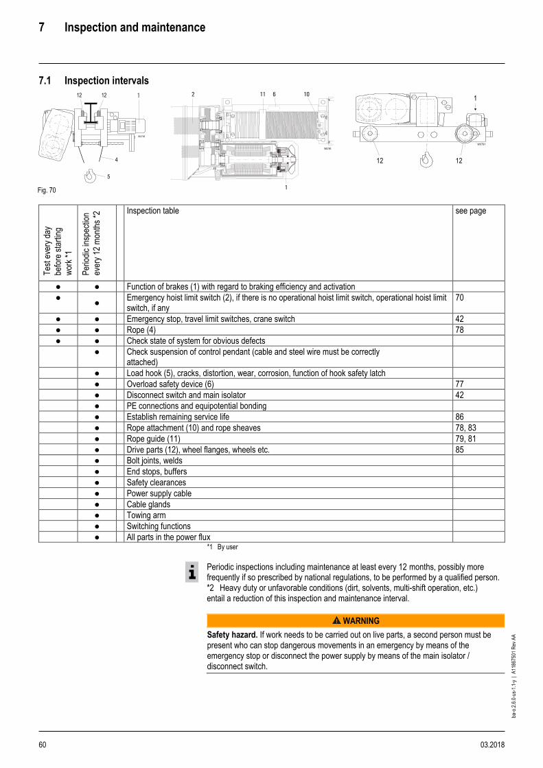
7 Inspection and maintenance
60 03.2018
ba-o
.2.6
.0-u
s-1.
1-y
| A
1186
7501
Rev
AA
7.1 Inspection intervals
Fig. 70
Tes
t eve
ry d
ay
befo
re s
tart
ing
wor
k *1
Per
iodi
c in
spec
tion
ever
y 12
mon
ths
*2 Inspection table see page
● ● Function of brakes (1) with regard to braking efficiency and activation
● ●
Emergency hoist limit switch (2), if there is no operational hoist limit switch, operational hoist limit switch, if any
70
● ● Emergency stop, travel limit switches, crane switch 42
● ● Rope (4) 78
● ● Check state of system for obvious defects
● Check suspension of control pendant (cable and steel wire must be correctly attached)
● Load hook (5), cracks, distortion, wear, corrosion, function of hook safety latch
● Overload safety device (6) 77
● Disconnect switch and main isolator 42
● PE connections and equipotential bonding
● Establish remaining service life 86
● Rope attachment (10) and rope sheaves 78, 83
● Rope guide (11) 79, 81
● Drive parts (12), wheel flanges, wheels etc. 85
● Bolt joints, welds
● End stops, buffers
● Safety clearances
● Power supply cable
● Cable glands
● Towing arm
● Switching functions
● All parts in the power flux *1 By user
Periodic inspections including maintenance at least every 12 months, possibly more frequently if so prescribed by national regulations, to be performed by a qualified person. *2 Heavy duty or unfavorable conditions (dirt, solvents, multi-shift operation, etc.) entail a reduction of this inspection and maintenance interval.
WARNING
Safety hazard. If work needs to be carried out on live parts, a second person must be present who can stop dangerous movements in an emergency by means of the emergency stop or disconnect the power supply by means of the main isolator / disconnect switch.
W0789
12
5
4
121
1212
W0791

7 Inspection and maintenance
03.2018 61
ba-o
.2.6
.0-u
s-1.
1-y
| A
1186
7501
Rev
AA
7.2 Maintenance intervals
Fig. 71
Per
iodi
c in
spec
tion
ever
y 12
mon
ths
*2
Wor
k ev
ery
5 ye
ars
Wor
k ev
ery
10
year
s
Maintenance table see page
● Brake (20), measure air gap, replace brake disk if necessary 63, 64, 65
● Overload safety device (21) 77
● Grease rope (22) with brush 101
● Grease rope guide (23) with brush 101
● Tighten clamping points for electric cables
● Oil change (normal mode) 101
● Oil change in case of ambient temperatures 131°F and engine rating M7 and higher 101
Periodic inspections including maintenance at least every 12 months, possibly more frequently if so prescribed by national regulations, to be performed by a qualified person. *2 Heavy duty or unfavorable conditions (dirt, solvents, multi-shift operation, etc.) entail a reduction of this inspection and maintenance interval.
NOTICE
Material damage hazard. If increased wear or damage is ascertained when inspecting or maintaining the hoist, the latter must not be put into operation again until the faults have been eliminated.
W0792
22
20 23 21
20
W0793
20
W0794
7 Inspection and maintenance
62 03.2018
ba-o
.2.6
.0-u
s-1.
1-y
| A
1186
7501
Rev
AA
7.3 Motors
DANGER
Electric shock hazard. Some motor parts are live. Any contact with live parts can cause severe injury or death. Motors have dangerous rotating parts and hot surfaces.
Ensure that:
• the motor runs correctly (e.g. no variations in speed, no noise emission),
• there are no strong vibrations.
The insulation resistance must be checked after a long period of storage or shutdown, if possible at a winding temperature of +68°F … +86°F. Before starting to measure the insulation resistance, pay attention to the operating instructions of the insulation measurement instrument being used. Measuring voltage: 500 V. Minimum insulation resistance for new, cleaned or overhauled windings: 10 MΩ. Critical specific insulation resistance after a long period of operation: 0.5 MΩ / kV. If the critical insulation resistance is reached or undershot, the windings must be dried, or thoroughly cleaned and dried after removing the rotor.
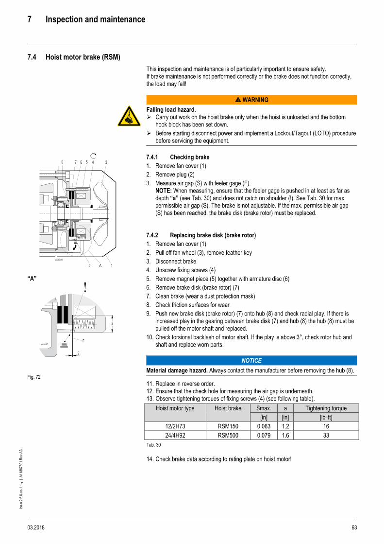
7 Inspection and maintenance
03.2018 63
ba-o
.2.6
.0-u
s-1.
1-y
| A
1186
7501
Rev
AA
7.4 Hoist motor brake (RSM)
This inspection and maintenance is of particularly important to ensure safety. If brake maintenance is not performed correctly or the brake does not function correctly, the load may fall!
WARNING
Falling load hazard. ➢ Carry out work on the hoist brake only when the hoist is unloaded and the bottom
hook block has been set down.
➢ Before starting disconnect power and implement a Lockout/Tagout (LOTO) procedure before servicing the equipment.
7.4.1 Checking brake
1. Remove fan cover (1)
2. Remove plug (2)
3. Measure air gap (S) with feeler gage (F). NOTE: When measuring, ensure that the feeler gage is pushed in at least as far as depth “a” (see Tab. 30) and does not catch on shoulder (!). See Tab. 30 for max. permissible air gap (S). The brake is not adjustable. If the max. permissible air gap (S) has been reached, the brake disk (brake rotor) must be replaced.
7.4.2 Replacing brake disk (brake rotor)
1. Remove fan cover (1)
2. Pull off fan wheel (3), remove feather key
3. Disconnect brake
4. Unscrew fixing screws (4)
5. Remove magnet piece (5) together with armature disc (6)
6. Remove brake disk (brake rotor) (7)
7. Clean brake (wear a dust protection mask)
8. Check friction surfaces for wear
9. Push new brake disk (brake rotor) (7) onto hub (8) and check radial play. If there is increased play in the gearing between brake disk (7) and hub (8) the hub (8) must be pulled off the motor shaft and replaced.
10. Check torsional backlash of motor shaft. If the play is above 3°, check rotor hub and shaft and replace worn parts.
NOTICE
Material damage hazard. Always contact the manufacturer before removing the hub (8).
“A”
Fig. 72
11. Replace in reverse order. 12. Ensure that the check hole for measuring the air gap is underneath. 13. Observe tightening torques of fixing screws (4) (see following table).
Hoist motor type Hoist brake Smax. a Tightening torque
[in] [in] [lbf ft]
12/2H73 RSM150 0.063 1.2 16
24/4H92 RSM500 0.079 1.6 33
Tab. 30
14. Check brake data according to rating plate on hoist motor!

7 Inspection and maintenance
64 03.2018
ba-o
.2.6
.0-u
s-1.
1-y
| A
1186
7501
Rev
AA
7.5 Hoist motor brake (NM) (pole-changing)
WARNING
Falling load hazard. ➢ Carry out work on the hoist brake only when the hoist is unloaded and the bottom
hook block has been set down.
➢ Before starting disconnect power and implement a Lockout/Tagout (LOTO) procedure before servicing the equipment.
Fig. 73
7.5.1 Checking brake
1. Remove fan cover (1)
2. Remove plug (2)
3. Measure air gap (S) with feeler gage (F). NOTE: When measuring, ensure that the feeler gage is pushed in at least as far as depth “a” (see Tab. 31) and does not catch on shoulder (!). See Tab. 31 for max. permissible air gap (S). The brake is not adjustable. If the max. permissible air gap (S) has been reached, the brake disk (brake rotor) must be replaced.
7.5.2 Replacing brake disk (brake rotor)
1. Remove fan cover (1)
2. Pull off fan wheel (3), remove bushing with V-ring (IP 66)
3. Disconnect brake
4. Unscrew fixing screws (4)
5. Remove magnet piece (5) together with armature disc (6)
6. Remove brake disk (brake rotor) (7)
7. Clean brake (wear a dust protection mask)
8. Check friction surfaces for wear
9. Push new brake disk (brake rotor) (7) onto hub (8) and check radial play. If there is increased play in the gearing between brake disk (7) and hub (8) the hub (8) must be pulled off the motor shaft and replaced.
NOTICE
Material damage hazard. Always contact the manufacturer before removing the hub (8).
10. Replace in reverse order.
11. Ensure that the check hole for measuring the air gap is underneath.
12. Observe tightening torques of fixing screws (4) (see following table).
Hoist motor type Hoist brake Smax. a Tightening torque
[in] [in] [lbf ft]
12/2H33-MF10Z-106 NM38722 0.024 1 7
12/2H42-MF10X-106 NM38732 0.024 1 7
12/2H62-MF11X-106 NM38742 0.031 1 16
12/2H71-MF11X-106 NM38742 0.031 1 16
12/2H72-MF13Z-106 NM38754 0.035 1.2 16
12/2H91-MF16ZC-106 NM38790 0.035 1.6 33
Tab. 31
1. Check brake data according to rating plate on hoist motor!
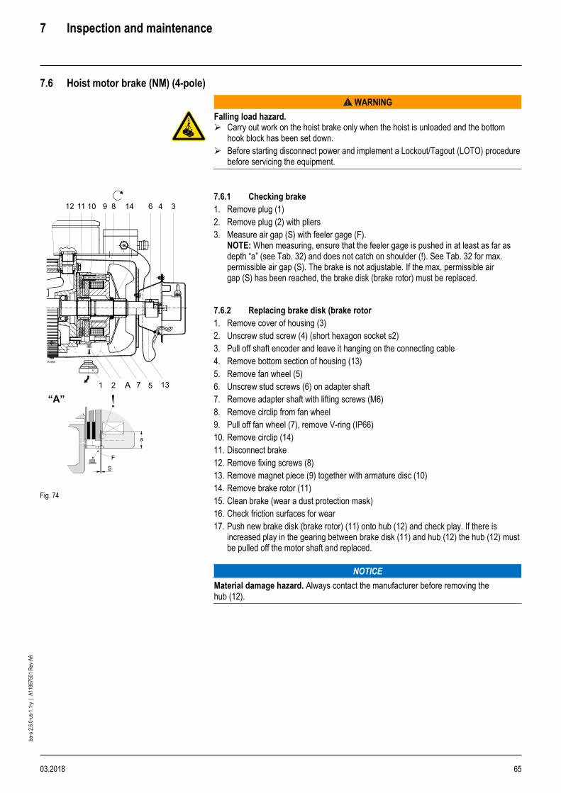
7 Inspection and maintenance
03.2018 65
ba-o
.2.6
.0-u
s-1.
1-y
| A
1186
7501
Rev
AA
7.6 Hoist motor brake (NM) (4-pole)
WARNING
Falling load hazard. ➢ Carry out work on the hoist brake only when the hoist is unloaded and the bottom
hook block has been set down.
➢ Before starting disconnect power and implement a Lockout/Tagout (LOTO) procedure before servicing the equipment.
Fig. 74
7.6.1 Checking brake
1. Remove plug (1)
2. Remove plug (2) with pliers
3. Measure air gap (S) with feeler gage (F). NOTE: When measuring, ensure that the feeler gage is pushed in at least as far as depth “a” (see Tab. 32) and does not catch on shoulder (!). See Tab. 32 for max. permissible air gap (S). The brake is not adjustable. If the max. permissible air gap (S) has been reached, the brake disk (brake rotor) must be replaced.
7.6.2 Replacing brake disk (brake rotor
1. Remove cover of housing (3)
2. Unscrew stud screw (4) (short hexagon socket s2)
3. Pull off shaft encoder and leave it hanging on the connecting cable
4. Remove bottom section of housing (13)
5. Remove fan wheel (5)
6. Unscrew stud screws (6) on adapter shaft
7. Remove adapter shaft with lifting screws (M6)
8. Remove circlip from fan wheel
9. Pull off fan wheel (7), remove V-ring (IP66)
10. Remove circlip (14)
11. Disconnect brake
12. Remove fixing screws (8)
13. Remove magnet piece (9) together with armature disc (10)
14. Remove brake rotor (11)
15. Clean brake (wear a dust protection mask)
16. Check friction surfaces for wear
17. Push new brake disk (brake rotor) (11) onto hub (12) and check play. If there is increased play in the gearing between brake disk (11) and hub (12) the hub (12) must be pulled off the motor shaft and replaced.
NOTICE
Material damage hazard. Always contact the manufacturer before removing the hub (12).

7 Inspection and maintenance
66 03.2018
ba-o
.2.6
.0-u
s-1.
1-y
| A
1186
7501
Rev
AA
18. Replace in reverse order.
19. Ensure that the check hole for measuring the air gap is aligned with the opening in the fan wheel cover.
20. Lock stud screws (6) with locking varnish.
21. Observe tightening torques of fixing screws (8) (see table below).
Hoist motor type Hoist brake Smax. a Tightening torque
[in] [in] [lbf ft]
4H33-MF10MB-200 NM38720 0.024 1 7
4H42-MF10MC-200 NM38730 0.024 1 7
4H62-MF11MA-200 NM38740 0.031 1 16
4H71-MF11MB-200 NM38740 0.031 1 16
4H72-MF13Z-200 NM38741 0.031 1.2 16
4H73-MF13ZB-200 NM38753 0.035 1.2 16
4H81-MF13ZC-200 NM38753 0.035 1.2 16
4H82-MF13X-200 NM38781 0.035 1.2 16
Tab. 32
22. Check brake data according to rating plate on hoist motor!
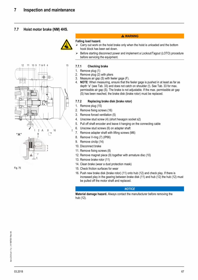
7 Inspection and maintenance
03.2018 67
ba-o
.2.6
.0-u
s-1.
1-y
| A
1186
7501
Rev
AA
7.7 Hoist motor brake (NM) 4HS.
WARNING
Falling load hazard. ➢ Carry out work on the hoist brake only when the hoist is unloaded and the bottom
hook block has been set down.
➢ Before starting disconnect power and implement a Lockout/Tagout (LOTO) procedure before servicing the equipment.
Fig. 75
7.7.1 Checking brake
1. Remove plug (1) 2. Remove plug (2) with pliers 3. Measure air gap (S) with feeler gage (F). 4. NOTE: When measuring, ensure that the feeler gage is pushed in at least as far as
depth “a” (see Tab. 33) and does not catch on shoulder (!). See Tab. 33 for max. permissible air gap (S). The brake is not adjustable. If the max. permissible air gap (S) has been reached, the brake disk (brake rotor) must be replaced.
7.7.2 Replacing brake disk (brake rotor)
1. Remove plug (15)
2. Remove fixing screws (16)
3. Remove forced ventilation (5)
4. Unscrew stud screw (4) (short hexagon socket s2)
5. Pull off shaft encoder and leave it hanging on the connecting cable
6. Unscrew stud screws (6) on adapter shaft
7. Remove adapter shaft with lifting screws (M6)
8. Remove V-ring (7) (IP66)
9. Remove circlip (14)
10. Disconnect brake
11. Remove fixing screws (8)
12. Remove magnet piece (9) together with armature disc (10)
13. Remove brake rotor (11)
14. Clean brake (wear a dust protection mask)
15. Check friction surfaces for wear
16. Push new brake disk (brake rotor) (11) onto hub (12) and check play. If there is increased play in the gearing between brake disk (11) and hub (12) the hub (12) must be pulled off the motor shaft and replaced.
NOTICE
Material damage hazard. Always contact the manufacturer before removing the hub (12).
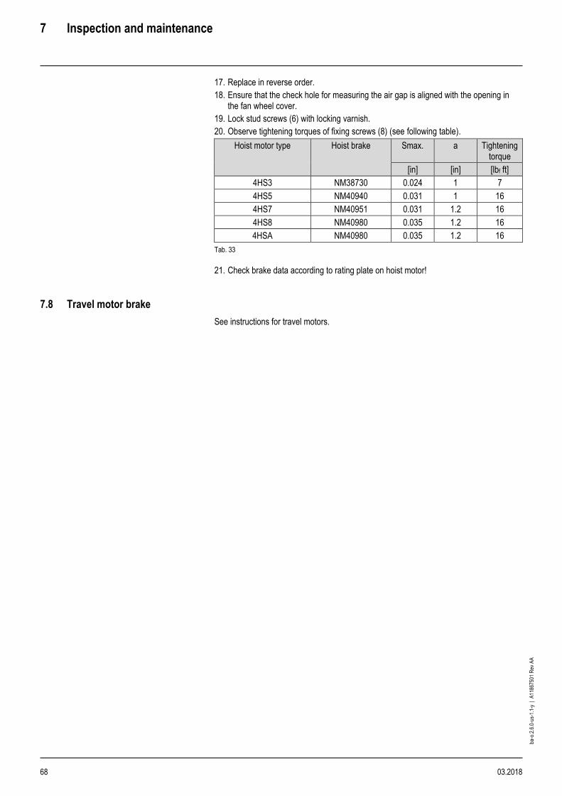
7 Inspection and maintenance
68 03.2018
ba-o
.2.6
.0-u
s-1.
1-y
| A
1186
7501
Rev
AA
17. Replace in reverse order.
18. Ensure that the check hole for measuring the air gap is aligned with the opening in the fan wheel cover.
19. Lock stud screws (6) with locking varnish.
20. Observe tightening torques of fixing screws (8) (see following table).
Hoist motor type Hoist brake Smax. a Tightening torque
[in] [in] [lbf ft]
4HS3 NM38730 0.024 1 7
4HS5 NM40940 0.031 1 16
4HS7 NM40951 0.031 1.2 16
4HS8 NM40980 0.035 1.2 16
4HSA NM40980 0.035 1.2 16
Tab. 33
21. Check brake data according to rating plate on hoist motor!
7.8 Travel motor brake
See instructions for travel motors.
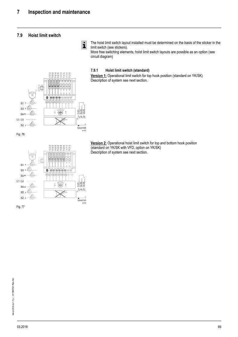
7 Inspection and maintenance
03.2018 69
ba-o
.2.6
.0-u
s-1.
1-y
| A
1186
7501
Rev
AA
7.9 Hoist limit switch
The hoist limit switch layout installed must be determined on the basis of the sticker in the limit switch (see stickers). More free switching elements, hoist limit switch layouts are possible as an option (see circuit diagram)
Fig. 76
7.9.1 Hoist limit switch (standard)
Version 1: Operational limit switch for top hook position (standard on YK/SK) Description of system see next section.
Fig. 77
Version 2: Operational hoist limit switch for top and bottom hook position (standard on YK/SK with VFD, option on YK/SK) Description of system see next section.

7 Inspection and maintenance
70 03.2018
ba-o
.2.6
.0-u
s-1.
1-y
| A
1186
7501
Rev
AA
7.10 Hoist limit switch
Fig. 78 *1 Effective hook path
Wire rope hoist type YK/SK
Minimum clearance a [in]
50 Hz 60 Hz
1PS 1PD
5.1 5.9
2PS 2PD
2.8 3.1
4PS 1.6 2
Tab. 34
7.10.1 Description of hoist limit switch system
• The wire rope hoist is equipped as standard with an emergency hoist limit switch for disconnecting in top and bottom hook position (switching points A↑ and A↓).
• The hoist is also equipped with an operational hoist limit switch for disconnecting in top hook position during normal operation (switching points B↑ and B↑↑).
• Switching point B↑↑ disconnects the fast speed and B↑ the slow speed in upwards direction.
• If the operational limit switch (B↑, B↑↑) is overrun during a malfunction, the emergency hoist limit switch (A↑) disconnects the main contactor / hoist contactor. The hoist can only leave the hoist limit switch area by activating switch S261 in the hoist control after the fault has been eliminated.
• The hoist limit switch (S220) is in the panel box on the gear.
• For version 2, an additional operational hoist limit switch for disconnecting in bottom hook position during normal operation is fitted as an option (switching points B↓, B↓↓).
• Switching point B↓↓ disconnects the fast speed and B↓ the slow speed in downwards direction.
• If the operational limit switch (B↓, B↓↓) is overrun during a malfunction, the emergency hoist limit switch (A↓) disconnects the main contactor / hoist contactor. The hoist can only leave the hoist limit switch area by activating switch S261 in the hoist control after the fault has been eliminated.
7.10.2 Testing emergency hoist limit switch, version 1
1. Test at slow speed without load.
2. Activate the “up” button on the control pendant carefully, observing the hoisting motion, until the hoist limit switch disconnects in the highest operational hook position (B↑).
3. Activate the override button (S260) in the control and at the same time the “up” button until the emergency hoist limit switch disconnects (A↑). If the hoist does not continue to move, the emergency hoist limit switch has already switched off in step 1 and the operational hoist limit switch is not functioning.
4. Minimum clearance “a” between bottom hook block and the nearest obstacle, see Tab. 34, or hook dimension C -2.4 in, see Tab. 37, page 76 must be maintained at least, depending on which dimension is larger.
5. Activate the override button (S261) in the control panel and at the same time the "down" button to leave the hoist limit switch area.
6. Activate the “down” button on the control pendant until the emergency hoist limit switch disconnects (A↓).
7. Minimum clearance between rope guide (S) and clamping claws (K) for rope anchorage = 0.79 in, if necessary reset hoist limit switch (see page 72, section 7.10.6 “Setting hoist limit switch”).
7.10.3 Testing operational hoist limit switch, version 1
1. Test without load. 2. Activate the “up” button on the control pendant carefully, observing the hoisting
motion, until the hoist limit switch disconnects in the highest operational hook position (B↑).
3. The hoist must be switched over to slow speed (B↑↑) before reaching cut-off point (B↑).
4. Minimum clearance a + 2.4 in between bottom hook block and the nearest obstacle, (see table above left), or the hook dimension “C”, see Tab. 37, page 76 must be maintained at least, depending on which dimension is greater. If necessary reset hoist limit switch, see page 72.
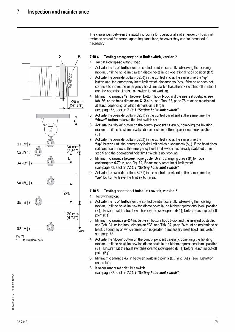
7 Inspection and maintenance
03.2018 71
ba-o
.2.6
.0-u
s-1.
1-y
| A
1186
7501
Rev
AA
The clearances between the switching points for operational and emergency hoist limit switches are set for normal operating conditions, however they can be increased if necessary.
Fig. 79 *1 Effective hook path
7.10.4 Testing emergency hoist limit switch, version 2
1. Test at slow speed without load.
2. Activate the “up” button on the control pendant carefully, observing the hoisting motion, until the hoist limit switch disconnects in top operational hook position (B↑).
3. Activate the override button (S260) in the control and at the same time the “up” button until the emergency hoist limit switch disconnects (A↑). If the hoist does not continue to move, the emergency hoist limit switch has already switched off in step 1 and the operational hoist limit switch is not working.
4. Minimum clearance “a” between bottom hook block and the nearest obstacle, see tab. 36. or the hook dimension C -2.4 in., see Tab. 37, page 76 must be maintained at least, depending on which dimension is larger (see page 72, section 7.10.6 “Setting hoist limit switch”).
5. Activate the override button (S261) in the control panel and at the same time the “down” button to leave the limit switch area.
6. Activate the “down” button on the control pendant carefully, observing the hoisting motion, until the hoist limit switch disconnects in bottom operational hook position (B↓).
7. Activate the override button (S262) in the control and at the same time the “up” button until the emergency hoist limit switch disconnects (A↓). If the hoist does not continue to move, the emergency hoist limit switch has already switched off in step 5 and the operational hoist limit switch is not working.
8. Minimum clearance between rope guide (S) and clamping claws (K) for rope anchorage = 0.79 in, see Fig. 79, if necessary reset hoist limit switch (see page 72, section 7.10.6 “Setting hoist limit switch”).
9. Activate the override button (S261) in the control panel and at the same time the “up” button to leave the limit switch area.
7.10.5 Testing operational hoist limit switch, version 2
1. Test without load.
2. Activate the “up” button on the control pendant carefully, observing the hoisting motion, until the hoist limit switch disconnects in the highest operational hook position (B↑). Ensure that the hoist switches over to slow speed (B↑↑) before reaching cut-off point (B↑).
3. Minimum clearance a+2.4 in. between bottom hook block and the nearest obstacle, see Tab. 34, or the hook dimension “C”, see Tab. 37, page 76 must be maintained at least, depending on which dimension is greater. If necessary reset hoist limit switch, see page 72.
4. Activate the “down” button on the control pendant carefully, observing the hoisting motion, until the hoist limit switch disconnects in the highest operational hook position (B↓). Ensure that the hoist switches over to slow speed (B↓↓) before reaching cut-off point (B↓).
5. Minimum clearance 4.7 in between switching points (B↓) and (A↓), (see illustration on the left)
6. If necessary reset hoist limit switch (see page 72, section 7.10.6 “Setting hoist limit switch”).

7 Inspection and maintenance
72 03.2018
ba-o
.2.6
.0-u
s-1.
1-y
| A
1186
7501
Rev
AA
7.10.6 Setting hoist limit switch
DANGER
Electric shock hazard The cover of the hoist limit switch must be removed to set the contacts. This exposes live contact connections. Make sure an electrical qualified person performs the work.
Fig. 80
Fig. 81 *1 Effective hook path
Adjust hoist limit switch at the setscrews (S1) - (S6) depending on version: Turning to the left: switching point is moved “downwards”. Turning to the right: switching point is moved “upwards”. Adjusting en bloc All the cam discs can be moved together with the aid of the black setscrew (S0). The settings of the individual contacts relative to one another remain unchanged (see Fig. 80). Set the limit switch using socket spanner (04 430 50 99 0) and without using undue force. Do not use a power screwdriver. Adjust the switching points in the following sequence: 1. A↑ (S1)
2. B↑ (S3)
3. B↑↑ (S4)
4. A↓ (S2)
5. B↓ (S5) (option)
6. B↓↓ (S6) (option) When setting the hoist limit switch, observe hook dimension “C” as specified on page 76, section 7.11 “Hook dimensions C for KE-S.. trolleys”. Switching point A↑ (S1) Emergency hoist limit switch top hook position
1. Set without load in creep lifting.
2. Lift bottom hook block to a+0.39 in. (see illustration left and table below) or the hook dimension C-2 in. see Tab. 37, page 76, depending on which dimension is greater If necessary turn setscrew (S1) to the right beforehand.
3. Turn setscrew (S1) to the left until contact S1 switches audibly.
4. Activate override button (S261) in control panel and at the same time “down” button to leave the hoist limit switch area.
5. Check cut-off point at fast and slow speed.
Wire rope hoist type
YK/SK
a [in]
50 Hz 60 Hz
1PS 1PD
5.1 5.9
2PS 2PD
2.8 3.1
4PS 1.6 2
Tab. 35
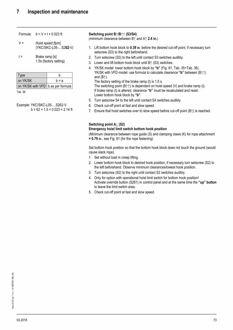
7 Inspection and maintenance
03.2018 73
ba-o
.2.6
.0-u
s-1.
1-y
| A
1186
7501
Rev
AA
Formula:
b = V × t × 0.023 ft
V = Hoist speed [fpm] (YKC/SKC-L05-…S262-V)
t = Brake ramp [s] 1.5s (factory setting)
Type b
on YK/SK b = a
on YK/SK with VFD b as per formula
Tab. 36
Example: YKC/SKC-L05-…S262-V b = 62 × 1.5 × 0.023 = 2.14 ft
Switching point B↑/B↑↑ (S3/S4) (minimum clearance between B↑ and A↑ 2.4 in.) 1. Lift bottom hook block to 0.39 in. before the desired cut-off point, if necessary turn
setscrew (S3) to the right beforehand.
2. Turn setscrew (S3) to the left until contact S3 switches audibly.
3. Lower and lift bottom hook block until B↑ (S3) switches.
4. YK/SK model: lower bottom hook block by “b” (Fig. 81, Tab. 35+Tab. 36). YK/SK with VFD model: use formula to calculate clearance “b” between (B↑↑) and (B↑). The factory setting of the brake ramp (t) is 1.5 s. The switching point (B↑↑) is dependent on hoist speed (V) and brake ramp (t). If brake ramp (t) is altered, clearance “b” must be recalculated and reset. Lower bottom hook block by “b”.
5. Turn setscrew S4 to the left until contact S4 switches audibly.
6. Check cut-off point at fast and slow speed.
7. Ensure that hoist switches over to slow speed before cut-off point (B↑) is reached. Switching point A↓ (S2) Emergency hoist limit switch bottom hook position
(Minimum clearance between rope guide (S) and clamping claws (K) for rope attachment = 0.79 in., see Fig. 81 (for the rope fastening) Set bottom hook position so that the bottom hook block does not touch the ground (would cause slack rope).
1. Set without load in creep lifting.
2. Lower bottom hook block to desired hook position, if necessary turn setscrew (S2) to the left beforehand. Observe minimum clearances/lowest hook position.
3. Turn setscrew (S2) to the right until contact S2 switches audibly.
4. Only for option with operational hoist limit switch for bottom hook position! Activate override button (S261) in control panel and at the same time the “up” button to leave the limit switch area.
5. Check cut-off point at fast and slow speed.

7 Inspection and maintenance
74 03.2018
ba-o
.2.6
.0-u
s-1.
1-y
| A
1186
7501
Rev
AA
Fig. 82 *1 Effective hook path
Switching point B↓/B↓↓ (S5/S6) (version 2 only) (Minimum clearance between B↓ and A↓ 4.7 in.) 1. Lower bottom hook block to 0.39 in. above desired hook position, if necessary turn
setscrew (S5) to the left beforehand. Observe minimum clearance, see Fig. 82.
2. Turn setscrew (S5) to the right until contact S5 switches audibly.
3. Lift and lower bottom hook block until B↓ (S5) is activated.
The following steps apply only for option operational hoist limit switch with pre-switching for bottom hook position! Type YK/SK: 1. Lift bottom hook block by 2xb, see Fig. 82, Tab. 35+Tab. 36.
Type YK/SK with VFD:
1. Use formula to calculate clearance 2xb between (B↓↓) and (B↓). The factory setting of the brake ramp (t) is 1.5 s. The switching point (B↓↓) is dependent on drum speed (V) and brake ramp (t). If brake ramp (t) is altered, clearance “b” must be recalculated and reset. Lift bottom hook block by 2xb.
2. Turn setscrew S6 to the right until contact S6 switches audibly.
3. Check cut-off point at fast and slow speed.
4. Ensure that hoist switches over to slow speed before cut-off point (B↓) is reached.
WARNING Safety hazard. Incorrectly set hoist limit switches may cause serious
accidents. Check operational hoist limit switch for function and correct setting every day.

7 Inspection and maintenance
03.2018 75
ba-o
.2.6
.0-u
s-1.
1-y
| A
1186
7501
Rev
AA
7.10.7 Servicing hoist limit switch
Maintenance work is restricted to checking the cut-off points. No maintenance or inspection is necessary for the hoist limit switch itself.
NOTICE
Material damage hazard. Any dust deposits that may be visible when the housing is opened must on no account be removed with compressed air as this would force the dust into the contacts and impair the switching function. On no account use benzene or other solvents to clean the hoist limit switch!

7 Inspection and maintenance
76 03.2018
ba-o
.2.6
.0-u
s-1.
1-y
| A
1186
7501
Rev
AA
7.11 Hook dimensions C for KE-S.. trolleys
The following hook dimensions C apply for the top operational hoist limit switch cut-off point (B↑).
WARNING
Hook dimension C must not be less than specified in the following. If the calculated flange width is between two values in the table, always set the larger dimension C.
DANGER
Safety hazard. Incorrectly set hoist limit switches may cause serious accidents. ➢ Check operational hoist limit switch for function and correct setting every day.
Fig. 83
Wire rope hoist Reeving Length Flange width
4.7 6.7 11.8 15.7 19.7
[in]
YKA/SKA 2PS -L2 -L3
19.3 18.5 21.3 24.2 27.2
4PS 16.5 15.9 18.9 21.9 24.6
2PD 15.4 14.8 18.5 21.3 24.2
YKB/SKB 2PS -L2 -L3
25 24.4 22.8 25.6 28.3
4PS 20.7 20.5 19.3 24 29.1
2PD 21.3 22.8 28.9 33.7 38.4
YKC/SKC
Drum tensile force
≤ 2500 daN
2PS -L2 -L3
26.2 26.2 26.2 26.6 29.3
4PS 24.2 23.6 21.9 23.2 25.8
2PD 20.1 19.3 19.7 22.6 25.4
2PS -L4 38.4 36.4 36.4 38.2 42.9
4PS 24.2 23.6 21.9 23.2 25.8
2PD 20.1 19.3 19.7 22.6 25.4
Drum tensile force
> 2500 daN
2PS -L2 -L3
28 27.6 31.1 35.2 39.4
4PS 25.4 24.8 29.1 33.5 37.8
2PD 20.3 22.4 28 32.1 36.2
YKE/SKE 2PS -L2 - 31.7 37.8 42.5 50
4PS - 29.3 30.1 35 39.8
2PS -L3 -L4
- 47.6 45.7 45.7 50
4PS - 29.3 27.8 28.7 31.7
2PS -L2 -L3 -L4
- 40.2 38.6 36.6 36.6
2PD - 33.1 31.3 29.7 29.9
4PS -L2 -L3 -L4 -L5
55.9
Tab. 37

7 Inspection and maintenance
03.2018 77
ba-o
.2.6
.0-u
s-1.
1-y
| A
1186
7501
Rev
AA
7.12 Overload safety device
7.12.1 Testing overload safety device
If an overload is detected, the wire rope hoist is switched off in the upwards direction. Only lowering is then possible. Lifting is not possible until the wire rope hoist has been unloaded. 1. Attach a test load of 100% maximum working load + 10% overload and take load up
slowly. After the rope is tautened the overload safety device must disconnect the hoist. If the hoist is not disconnected, see original operating instructions of overload device.
Fig. 84
Fig. 85
7.12.2 Maintenance of overload safety device with pressure sensor
1. After off-loading hoist, check all moving parts for ease of movement.
2. Clean without dismantling and grease from the outside with a thin-bodied lubricant.
7.12.3 Maintenance of overload safety device with shear force sensor
1. Check plate thickness (min. 0.059 in.)
2. If necessary, replace plate after removing screw (D).
7.13 Crane test
WARNING
Safety hazard. Make sure that the crane test is performed by a qualified person.
Test loads must be provided by the owner. The crane test is part of commissioning the wire rope hoist. The test comprises:
Dynamic test: 1.1 × maximum working load Test each direction of movement at slow and fast speed. The crane must operate smoothly during the test.
Static test: 1.25 × maximum working load The test load must not be lifted more than max. 7.9 in from the ground at slow speed during the static test.
To enable this test to be performed, a qualified person can raise the overload cut-off threshold following the original operating instructions of the overload device.
W0788

7 Inspection and maintenance
78 03.2018
ba-o
.2.6
.0-u
s-1.
1-y
| A
1186
7501
Rev
AA
7.14 Rope drive
7.14.1 Rope and rope attachment - general information
After commissioning a new wire rope hoist, or after replacing the rope, the rope of multi-fall hoists may twist. This can be seen from the bottom hook block turning, particularly when unloaded.
WARNING
Damaged or twisted rope hazard. Twisting in the rope prejudices safety and service life. ➢ Remove any twists!
WARNING
Wire fracture hazard. In certain applications (e.g. twist-free wire rope, constant deadweight, recurrent stopping position, automatic operation, vibrations etc.) wire fractures may occur inside the rope without being visible from outside. Risk of accident! ➢ In case of doubt please contact the manufacturer.
1. Regularly inspect the rope for twisting. To do so, run the hoist into highest and lowest
hook positions without load.
2. If any twisting is detected, untwist the rope immediately (see page 48, section 4.11 “Reeving rope” and page 80, “Removing rope”).
3. Check rope. Take particular note of the sections of rope near rope pulleys, return pulleys or equalizing pulleys and in the region of the rope anchorage.
4. If any of the following damage should occur, replace the rope immediately.
– Excess visible wire fractures, see page 79, section 7.14.2. “Replacement of wire rope due to broken wires”.
– The rope must be free of load for testing to facilitate detecting any broken wires when bending the rope by hand (approximately by radius of rope sheave).
– Nest of wire fractures or broken strand.
– In case of equal diameter reduction of 5% along the rope
– In case of a local diameter reduction, e.g. if a rope core fails
– Formation of baskets or loops, knots, kinks, kink or other mechanical damage.
– Corkscrew-type deformation. Divergence due to deformation: ≥ 1/10 × rope diameter.
– In case of a projecting core or strands
– In case the rope diameter is increased >=5%
– In case of external corrosion like severely worn wire surfaces, slack wires
– In case of internal corrosion, e.g. corrosion particles released from the valleys between external strands
– In case of damage due to heat effects or an arc with corresponding external heat discoloration on the wires or clear loss of lubricants
– In addition, the rope must be replaced as required by ISO 4309. In case of wire breakage in the strand valleys of 2 or more on 6 × d, set down the wire rope (danger of internal wire breaks)
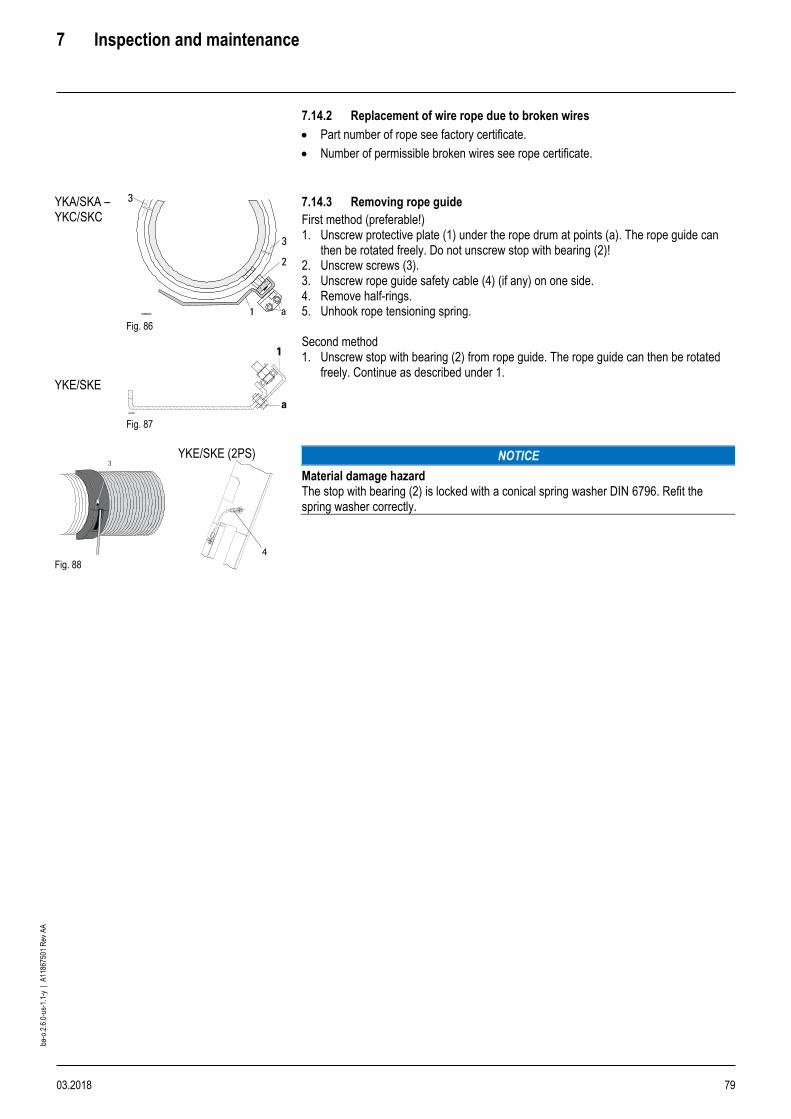
7 Inspection and maintenance
03.2018 79
ba-o
.2.6
.0-u
s-1.
1-y
| A
1186
7501
Rev
AA
7.14.2 Replacement of wire rope due to broken wires
• Part number of rope see factory certificate.
• Number of permissible broken wires see rope certificate.
YKA/SKA – YKC/SKC YKE/SKE
Fig. 86
Fig. 87
7.14.3 Removing rope guide
First method (preferable!) 1. Unscrew protective plate (1) under the rope drum at points (a). The rope guide can
then be rotated freely. Do not unscrew stop with bearing (2)! 2. Unscrew screws (3). 3. Unscrew rope guide safety cable (4) (if any) on one side. 4. Remove half-rings. 5. Unhook rope tensioning spring.
Second method 1. Unscrew stop with bearing (2) from rope guide. The rope guide can then be rotated
freely. Continue as described under 1.
Fig. 88
YKE/SKE (2PS)
NOTICE
Material damage hazard The stop with bearing (2) is locked with a conical spring washer DIN 6796. Refit the spring washer correctly.

7 Inspection and maintenance
80 03.2018
ba-o
.2.6
.0-u
s-1.
1-y
| A
1186
7501
Rev
AA
7.14.4 Replacing wire rope
YK/SK wire rope hoists have a special rope which is the optimum for the most common applications.
WARNING
Hazard from unsuitable rope The substitute rope must be equivalent to the original in terms of quality, strength and make-up. Please consult the works certificate or the rope certificate to see which rope is fitted. ➢ Always insert the rope correctly into the rope anchorage and secure. Replace split pin
every time it is dismantled
Fig. 89
Fig. 90
Fig. 91
Removing wire rope 1. Lower bottom hook block to just above the lowest hook position and set it down on a
firm support.
2. Release end of wire rope in rope anchorage (rope clamp with rope wedge).
3. Run the remaining rope off the drum.
4. Unscrew the fixing screws in the clamping plates on the rope drum. Fitting rope 1. Unroll new rope out straight if possible, without twists, kinks or loops. Protect rope
from dirt.
2. Attach rope to rope drum with all the clamping plates (do not forget the lock washers!). Allow the rope end to project by approx. 1.2-1.6 in.
3. Tightly wind about 5-10 turns onto the drum under power. Let the rope run through a greased rag. For type of grease see page 101.
4. Fit rope guide (see page 81, section 7.14.5 “Fitting rope guide”).
5. Reeve the loose end of the rope according to the number of falls, fasten with the rope wedge and secure with a rope clamp, see section “Rope anchorage”.
6. Retighten clamping plates with the specified tightening torques (see following table):
Type Metric size Tightening torque
[lbf ft]
YKA/SKA M6 7.4
M10 29.5
YKB/SKB M10 37
YKC/SKC M10 37
M12 64
YKE/SKE M12 M16
64 155
Tab. 38
7. Run rope in with partial load. 8. WARNING Safety hazard. After fitting a new rope, or shortening the old one,
reset the hoist limit switch. See page 72, “Setting emergency hoist limit switch”. 9. Retract rope with partial load (see page 48, section 4.11 “Reeving rope”).
10. If the new rope twists after some time in operation, untwist the rope immediately (see page 48, section 4.11 “Reeving rope” and page 80, “Removing rope”).

7 Inspection and maintenance
03.2018 81
ba-o
.2.6
.0-u
s-1.
1-y
| A
1186
7501
Rev
AA
7.14.5 Fitting rope guide
Fig. 92
1. Grease thread and rope guide groove thoroughly.
2. Place the half-ring (1) with the short window section onto the rope drum next to the last rope winding so that the rope exits from the region of the window (x).
(a) Special tool
3. With the special tool (a), push rope tensioning spring (2) into the guide groove of the half-ring (1) and hook the ends of the spring together.
4. Place the second half-ring (3) with the long rope exit window on the rope drum so that the rope exits from the drum groove through the window straight and without kinking. The second half-ring must lie flush against the first.
5. Bolt the two half-rings together with pressure screws and bolts (5)
6. The rope guide must rest lightly on the drum and must be able to be turned by hand. If this is not the case the guide has been fitted incorrectly or the rope drum is damaged.
7. Bolt stop with bearing and conical spring washer (6) to the rope guide with the specified tightening torque (see following table).
Type Size Tightening torque
lbf ft
YKA/SKA, YKB/SKB M8×1 15
YKC/SKC M10×1 30
YKD/SKD, YKE/SKE M16×1 118
Type YKE/SKE - 2PS L4-L5
Fig. 93
1. Fit rope guide safety cable (4).
2. Bolt on protective plate (8).

7 Inspection and maintenance
82 03.2018
ba-o
.2.6
.0-u
s-1.
1-y
| A
1186
7501
Rev
AA
7.14.6 Checking rope drum for wear
Fig. 94
Type of wire rope hoist
Rope diameter Nominal values Limits for wear
da di t da min di min t max
[in] [in] [in] [in] [in] [in] [in]
YKA/SKE 0.22 4.91 4.73 0.087 4.88 4.71 0.098
0.24 4.91 4.72 0.094 4.88 4.69 0.106
0.26 - 0.28 4.91 4.69 0.11 4.88 4.65 0.126
YKB/SKB 0.28 6.51 6.29 0.11 6.48 6.26 0.126
0.33 - 0.35 6.51 6.22 0.144 6.48 6.19 0.161
YKC/SKC 0.33 - 0.35 8.52 8.24 0.144 8.49 8.2 0.161
0.39 8.54 8.23 0.157 8.5 8.19 0.177
0.47 - 0.49 8.52 8.13 0.197 8.48 8.08 0.22
YKE/SKE 0.47 - 0.49 13.86 13.46 0.197 13.81 13.42 0.22
0.55 13.86 13.43 0.217 13.8 13.37 0.244
0.63 13.86 13.39 0.236 13.79 13.33 0.264
0.79 13.86 13.23 0.315 13.78 13.15 0.354
Tab. 39

7 Inspection and maintenance
03.2018 83
ba-o
.2.6
.0-u
s-1.
1-y
| A
1186
7501
Rev
AA
7.14.7 Inspection and maintenance of rope sheave
1. Check rope sheaves for wear.
We recommend having them checked by a qualified person. They should also be checked for easy running, indicating that the ball bearings are in good condition.
Wear on rope sheave Notes on limits for wear
Rope sheave
Part no. Ø D t
min
h
max
h
new
[in]
01 430 01 53 0 3.86 0.157 0.51 0.43
01 430 04 53 0 3.94 0.157 0.51 0.39
01 430 00 53 0 4.92 0.157 0.55 0.47
22 330 00 53 0 5.51 0.157 0.63 0.55
01 430 06 53 0 6.06 0.157 0.85 0.77
03 330 20 53 0 6.30 0.157 0.75 0.65
24 330 00 53 0 7.87 0.217 0.94 0.83
01 430 05 53 0 8.58 0.217 1.04 0.96
01 430 03 53 0 8.86 0.217 0.94 0.83
03 330 40 53 0 9.84 0.217 1.1 0.98
25 330 00 53 0 14.76 0.256 1.48 1.34
25 330 03 53 0 14.76 0.256 1.42 1.28
46 330 00 53 0 15.75 0.276 1.32 1.18
26 330 01 53 0 17.72 0.394 1.54 1.38
09 430 00 53 0 17.72 0.394 1.54 1.38
46 330 01 53 0 18.9 0.394 1.44 1.28
On one side and at base
On both sides and at base
Measuring depth of base of groove with depth gage
On both sides and at base
Measuring thickness of wall with special caliper gage
Tab. 40 Fig. 95
Fig. 96
The rope sheave must be replaced if the wall thickness as measured is <t min or the groove depth as measured is > h max. Furthermore, the rope sheave must be replaced when replacing the wire rope if the rope strands have dug into the base of the groove. Impressions of single wires are acceptable. A rope sheave must also be replaced if the radius of the base of the groove R has become too small for the new rope due to reduction in diameter of the old rope or wear.
The negative profile of the rope in the base of the groove may provide optimum contact to the wire rope currently fitted. Rope sheaves should be rotated without load on the rope to check the easy and concentric running of the bearings.
Bottom hook blocks
NOTICE
Danger of material damage. The bottom hook block must be checked for damage. Deformations, cracks and cuts caused by impact must be assessed. The damage can only be assessed by a qualified person.

7 Inspection and maintenance
84 03.2018
ba-o
.2.6
.0-u
s-1.
1-y
| A
1186
7501
Rev
AA
7.14.8 Checking load hook
Fig. 97
RSN,
RS
Hook size
025 04 05 08 1 1.6 2.5 4 5 6 10
[in]
h 0.94 1.14 1.22 1.46 1.57 1.89 2.28 2.64 2.95 3.35 4.17
h min 0.9 1.09 1.16 1.39 1.5 1.8 2.17 2.51 2.81 3.18 3.96
Tab. 41
Fig. 98
RSN,
RS
Hook size
2.5 4 5 6 10
[in]
h 1.97 2.36 2.64 2.95 3.74
h min 1.87 2.24 2.51 2.81 3.56
Tab. 42
ynew see hook certificate
yperm ≤ 1.1 × ynew
1. If value hmin and/or yperm are reached, replace hook.

7 Inspection and maintenance
03.2018 85
ba-o
.2.6
.0-u
s-1.
1-y
| A
1186
7501
Rev
AA
7.15 Trolley
Wheels, wheel drive and runway
Fig. 99
Fig. Nominal value Limit for wear
Ø d b Ø d1 b2
[in]
I 3.15 1.08 2.99 1.16
I 3.94 1.3 3.74 1.38
I 5.51
1.75 5.24
1.85
II 1.67 1.77
I 6.3 1.75 5.98 1.85
II 7.87 1.67 7.48 1.77
Tab. 43
Fig. 100
Fig.
Nominal value Limit for wear
Ø d bLR b k b1 Ø d1 b2 max play = (b*-k)
[in]
I 3.94 3.15
3.15
1.97
2.36
1.57
1.97
0.59
0.39
3.74 0.22
0.22
0.51
0.51
II 4.92 3.15
3.15
1.97
2.36
1.57
1.97
0.59
0.39
4.68 0.28
0.28
0.51
0.51
II 6.3 3.35
3.35
2.05
2.44
1.57
1.97
0.65
0.45
5.98 0.31
0.31
0.63
0.63
II 7.87 3.94
3.94
3.94
3.94
3.94
3.94
2.13
2.13
2.52
2.52
2.91
2.91
1.57
1.77
1.97
2.17
2.36
2.56
0.91
0.91
0.71
0.71
0.51
0.51
7.48 0.41
0.41
0.41
0.41
0.41
0.41
0.71
0.71
0.71
0.71
0.71
0.55
Tab. 44
1. Perform visual inspection of runway girder for wear.
2. Perform visual inspection of wheel flanges for wear.
3. Perform visual inspection of wheels for wear.
4. WARNING Safety risk. If any one of the limits for wear d1, b2, (b*-k) is attained,
the part must be replaced by a qualified person.

7 Inspection and maintenance
86 03.2018
ba-o
.2.6
.0-u
s-1.
1-y
| A
1186
7501
Rev
AA
7.16 Remaining service life
The operating mode and operating time must be established by the owner, see section 1.3 and recorded in the logbook in order to calculate the remaining service life. After the service life has expired a general overhaul (S.W.P. = Safe Working Period) must be carried out.
Fig. 101
7.16.1 Operating hours counter in SLE load monitor
The operating hours counter in the load monitor of the overload safety device adds up the operating time of the hoist. In order to obtain the lifetime expired in full load hours, the operating hours must be calculated with load factor “k”. This is carried out by a qualified person during the annual “periodic inspection”. If 90% of the theoretical full load lifetime has expired, a general overhaul (GO) must be scheduled and carried out at the earliest possible date.
A general overhaul must be completed after 10 years at the latest.
7.16.2 SMC multi-controller (optional)
The operating time of the hoist and the full load operating hours are recorded in the SMC. The SMC calculates the full load operating hours from the relevant hoisted load and the operating hours of the hoist. The remaining service life is calculated with reference to the mechanism group and can be read off by means of a PC (laptop). If the theoretical full load lifetime has expired, also indicated by an illuminated red LED, a general overhaul must be scheduled and carried out.
Reading the full load operating hours does not replace the prescribed tests including inspecting the wearing parts (rope, return sheaves...). .
7.17 General overhaul
The mechanism (motor and gear; not applicable to wearing parts) of the YK/SK wire rope hoist is classified according to ISO. The theoretical full load lifetime in hours shown opposite (D) is applicable for normal hoist applications.
ISO M4 M5 M6 M7
D [h] 800 1600 3200 6400
Tab. 45
If the full load lifetime (D) minus the lifetime expired is nought, the wire rope hoist must be overhauled by the manufacturer.
NOTICE
Danger of material damage. Components which are in the power flux may only be overhauled by the manufacturer. The rope drive is classified according to FEM 9.661, see factory certificate. As the service life of components such as gears is limited in accordance with the classification, it must be ensured that this is not exceeded. After the scheduled service life has expired hazards may arise. Thus the operator must take the responsibility for the remaining service life and the necessity of a general overhaul. We cannot accept any liability for damage occasioned by non-observance.
8 Wearing parts
03.2018 87
ba-o
.2.6
.0-u
s-1.
1-y
| A
1186
7501
Rev
AA
8 Wearing parts
WARNING
Safety hazard. ➢ Make sure that replacement and repairs are performed by qualified persons only.
8.1 Serial number
Fig. 102
When ordering original spare parts, always indicate the serial number of the hoist. This is affixed to the inside of the bearing support plate.
8.2 Hoist
RSM brake rotor
Fig. 103
Hoist motor Hoist motor brake
A Tightening torque
Order no. [lbf ft]
12/2H73 RSM150 A0443067650 16
24/4H92 RSM500 A0543010650 33
Tab. 46
NM brake rotor
Hoist motor Hoist motor brake A Tightening torque
Order no. [lbf ft]
12/2H33-MF.. 4H33-MF..
NM 38722 NM 38720
A5674770 A5674770
7
12/2H42-MF.. 4H42-MF.. 4HS3 4HA3
NM 38732 NM 38730 NM 38730 NM38730
A5674750 A5674750 A5676320 A5674780
7
12/2H62-MF.. 4H62-MF..
NM 38732 NM 38740
A5678050 A5674790
16
12/2H71-MF.. 4H71-MF.. 4HS5 4HA5
NM 38742 NM 38740 NM 40940 NM40940
A5674790 A5674790 A5676330 A5676490
16
12/2H72-MF.. 4H72-MF.. 4HS7
NM 38754 NM 38741 NM 40951
A5675700 A5675690 A5676340
16
4H73-MF.. 4SH8
NM 38753 NM 40980
A5675500 A5676350
16
4H81-MF NM 38753 A5675500 16
4H82-MF.. 4HSA
NM 38781 NM 40980
A5675710 A5676350
16
12/2H91 NM 38790 A5675910 33
Tab. 47

8 Wearing parts
88 03.2018
ba-o
.2.6
.0-u
s-1.
1-y
| A
1186
7501
Rev
AA
Rope guide
Fig. 104
Wire rope hoist type B C D
Order no. Order no. Order no.
YKA/SKA A0343002430 A0343001430 A0343000430
YKB/SKB A0443000430 A0443002430 A0443001430
YKC/SKC A0543001430 A0543002430 A0543000430
YKE/SKE (2PS), L4 - L5 A0643008430 - -
YKE/SKE A0643003430 A0643004430 A0643000430
Tab. 48
Fig. 105
Wire rope (E) See factory certificate or rope certificate for length and number of wire rope.

9 Troubleshooting
03.2018 89
ba-o
.2.6
.0-u
s-1.
1-y
| A
1186
7501
Rev
AA
9 Troubleshooting
DANGER
Electric shock hazard. ➢ Make sure an electrical qualified person performs the work. ➢ Disconnect power and implement a Lockout/Tagout (LOTO) procedure before
servicing the equipment.
Trouble Possible cause Remedy
Hoist does NOT operate No power to hoist 1. Check switches, and fuses.
2. Check connections in power supply lines.
3. Check power collectors.
Wrong voltage 1. Check if the supply voltage is in accordance with the voltage indicated on motor data plate.
Loose or broken wire connections 1. Shut off the power.
2. Remove electrical cover, and check wire connections.
3. Check wire connections of control pendant.
4. Check wire connections of limit switches.
5. Correct wiring if necessary.
Contactor not functioning 1. Check if jumper wires are properly installed.
2. Check if contactor armatures move freely.
3. Check if contactor is burned or welded.
4. Replace contactor if necessary.
No control voltage 1. Check if transformer fuse is blown.
2. If fuse is burn, check control pendant for grounding and/or shorts.
3. Check transformer coil for signs of overheating.
4. Check if the transformer secondary is the same voltage as the coils to which it is connected.
5. Replace transformer if necessary.
Motor burned out 1. Replace motor.
2. Check input power supply.
3. Check hoist motor connections.
Hoist does NOT operate,
motor hums
Not all power phases are present 1. Check fuses, replace if necessary
2. Check input power supply.
3. Check control pendant.
Hoist does NOT start after a longer shutdown, or starts with difficulty,
motor hums.
Hoist brake stuck 1. Check brake.
2. Replace brake if necessary.
Hoist motor overheats Excessive load 1. Reduce load to rated load of hoist, as shown on nameplate.
Excessive duty cycle 1. Reduce frequency of lifts.
2. Reduce amount of jogging.
Wrong voltage or frequency 1. Check if the supply voltage is in accordance with the voltage indicated on motor data plate.
2. Check hoist and inspect for defective, worn or damaged parts.
Defective motor or worn bearings in hoist frame
1. Disassemble hoist.
2. Inspect for defective, worn or damaged parts.
3. Replace parts if necessary.
Hoist operates intermittently Collectors make poor contact 1. Check electrical connections.
2. Check collectors for free movement of spring arms, or weak springs.
Loose contacts 1. Check wire connections.
2. Correct wiring if necessary.
Braking distance is too long Brake lining worn 1. Replace brake disk.
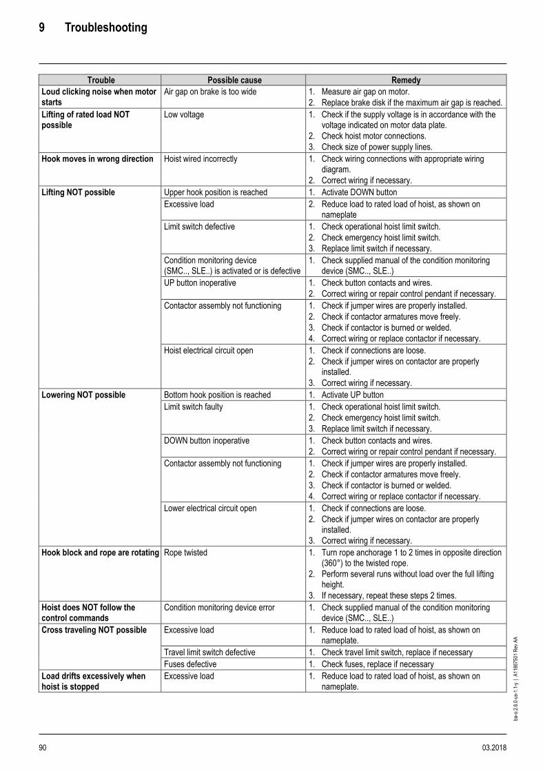
9 Troubleshooting
90 03.2018
ba-o
.2.6
.0-u
s-1.
1-y
| A
1186
7501
Rev
AA
Trouble Possible cause Remedy
Loud clicking noise when motor starts
Air gap on brake is too wide 1. Measure air gap on motor.
2. Replace brake disk if the maximum air gap is reached.
Lifting of rated load NOT possible
Low voltage 1. Check if the supply voltage is in accordance with the voltage indicated on motor data plate.
2. Check hoist motor connections.
3. Check size of power supply lines.
Hook moves in wrong direction Hoist wired incorrectly 1. Check wiring connections with appropriate wiring diagram.
2. Correct wiring if necessary.
Lifting NOT possible Upper hook position is reached 1. Activate DOWN button
Excessive load 2. Reduce load to rated load of hoist, as shown on nameplate
Limit switch defective
1. Check operational hoist limit switch.
2. Check emergency hoist limit switch.
3. Replace limit switch if necessary.
Condition monitoring device (SMC.., SLE..) is activated or is defective
1. Check supplied manual of the condition monitoring device (SMC.., SLE..)
UP button inoperative 1. Check button contacts and wires.
2. Correct wiring or repair control pendant if necessary.
Contactor assembly not functioning 1. Check if jumper wires are properly installed.
2. Check if contactor armatures move freely.
3. Check if contactor is burned or welded.
4. Correct wiring or replace contactor if necessary.
Hoist electrical circuit open 1. Check if connections are loose.
2. Check if jumper wires on contactor are properly installed.
3. Correct wiring if necessary.
Lowering NOT possible
Bottom hook position is reached 1. Activate UP button
Limit switch faulty
1. Check operational hoist limit switch.
2. Check emergency hoist limit switch.
3. Replace limit switch if necessary.
DOWN button inoperative 1. Check button contacts and wires.
2. Correct wiring or repair control pendant if necessary.
Contactor assembly not functioning 1. Check if jumper wires are properly installed.
2. Check if contactor armatures move freely.
3. Check if contactor is burned or welded.
4. Correct wiring or replace contactor if necessary.
Lower electrical circuit open 1. Check if connections are loose.
2. Check if jumper wires on contactor are properly installed.
3. Correct wiring if necessary.
Hook block and rope are rotating Rope twisted 1. Turn rope anchorage 1 to 2 times in opposite direction (360°) to the twisted rope.
2. Perform several runs without load over the full lifting height.
3. If necessary, repeat these steps 2 times.
Hoist does NOT follow the control commands
Condition monitoring device error 1. Check supplied manual of the condition monitoring device (SMC.., SLE..)
Cross traveling NOT possible
Excessive load 1. Reduce load to rated load of hoist, as shown on nameplate.
Travel limit switch defective 1. Check travel limit switch, replace if necessary
Fuses defective 1. Check fuses, replace if necessary
Load drifts excessively when hoist is stopped
Excessive load 1. Reduce load to rated load of hoist, as shown on nameplate.
10 Decommissioning
03.2018 91
ba-o
.2.6
.0-u
s-1.
1-y
| A
1186
7501
Rev
AA
10 Decommissioning
10.1 Dismantling
WARNING
Falling parts hazard ➢ Secure hoist when dismantling.
1. Dismantle hoist correctly. 2. First remove lubricants.
10.2 Scrap disposal
NOTICE
Electronic components, electric scrap, lubricants and other auxiliary substances are hazardous waste and may only be disposed of by approved recycling companies. Overload devices must be returned to the manufacturer.
Dismantled components must be recycled after correct dismantling. It is imperative to observe national regulations on environmentally compatible disposal. Local authorities will provide relevant information.
11 Technical data
92 03.2018
ba-o
.2.6
.0-u
s-1.
1-y
| A
1186
7501
Rev
AA
11 Technical data
11.1 Conditions of use
The hoist is designed for use in industry and for the ambient conditions usual in industry in non-hazardous areas. Special measures are necessary for particular applications such as e.g. high degree of chemical pollution, outdoor use, offshore application, etc. The manufacturer will be pleased to advise you. Protection against dust and moisture to EN 60529 See factory certificate Permissible ambient temperatures See factory certificate
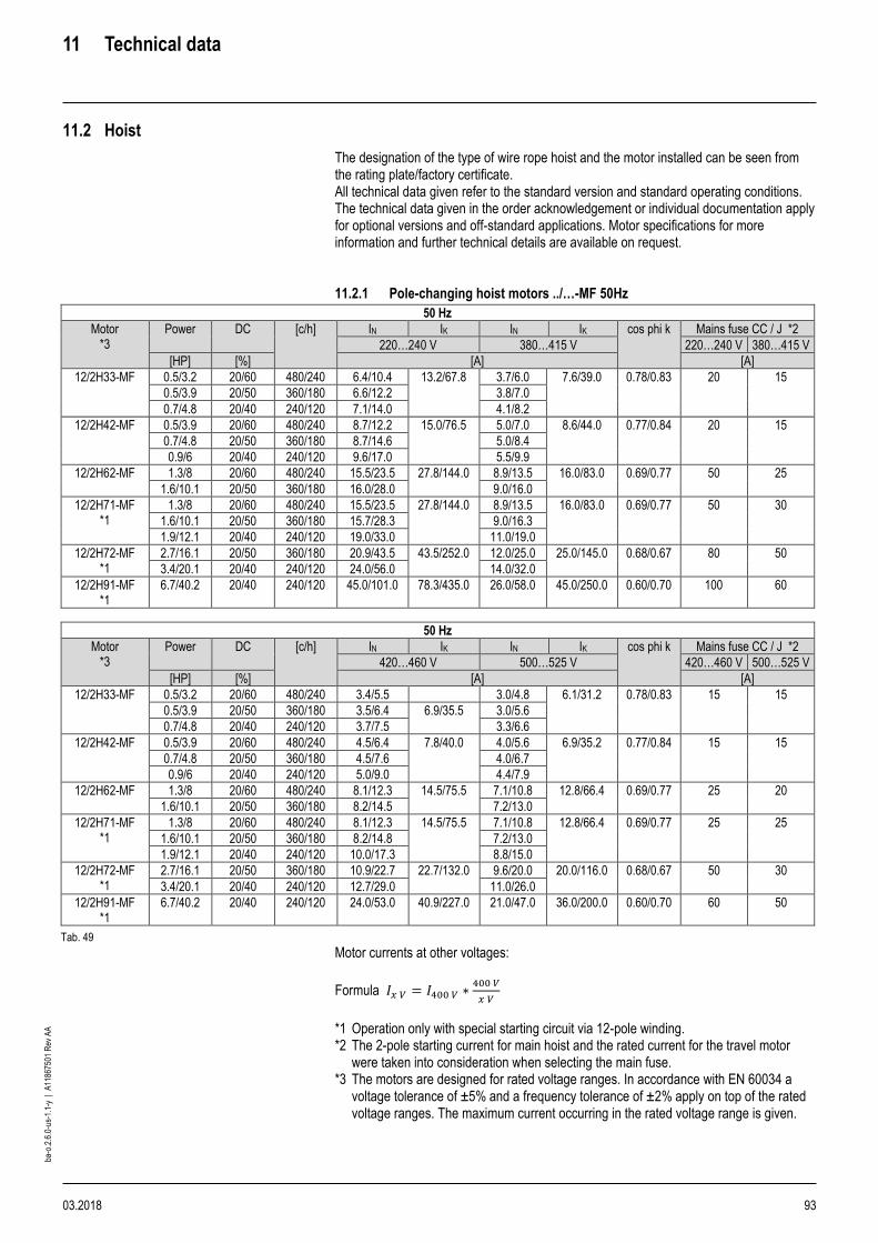
11 Technical data
03.2018 93
ba-o
.2.6
.0-u
s-1.
1-y
| A
1186
7501
Rev
AA
11.2 Hoist
The designation of the type of wire rope hoist and the motor installed can be seen from the rating plate/factory certificate. All technical data given refer to the standard version and standard operating conditions. The technical data given in the order acknowledgement or individual documentation apply for optional versions and off-standard applications. Motor specifications for more information and further technical details are available on request. 11.2.1 Pole-changing hoist motors ../…-MF 50Hz
50 Hz
Motor *3
Power DC [c/h] IN IK IN IK cos phi k Mains fuse CC / J *2
220…240 V 380…415 V 220…240 V 380…415 V
[HP] [%] [A] [A]
12/2H33-MF 0.5/3.2 20/60 480/240 6.4/10.4 13.2/67.8 3.7/6.0 7.6/39.0 0.78/0.83 20 15
0.5/3.9 20/50 360/180 6.6/12.2 3.8/7.0
0.7/4.8 20/40 240/120 7.1/14.0 4.1/8.2
12/2H42-MF 0.5/3.9 20/60 480/240 8.7/12.2 15.0/76.5 5.0/7.0 8.6/44.0 0.77/0.84 20 15
0.7/4.8 20/50 360/180 8.7/14.6 5.0/8.4
0.9/6 20/40 240/120 9.6/17.0 5.5/9.9
12/2H62-MF 1.3/8 20/60 480/240 15.5/23.5 27.8/144.0 8.9/13.5 16.0/83.0 0.69/0.77 50 25
1.6/10.1 20/50 360/180 16.0/28.0 9.0/16.0
12/2H71-MF *1
1.3/8 20/60 480/240 15.5/23.5 27.8/144.0 8.9/13.5 16.0/83.0 0.69/0.77 50 30
1.6/10.1 20/50 360/180 15.7/28.3 9.0/16.3
1.9/12.1 20/40 240/120 19.0/33.0 11.0/19.0
12/2H72-MF *1
2.7/16.1 20/50 360/180 20.9/43.5 43.5/252.0 12.0/25.0 25.0/145.0 0.68/0.67 80 50
3.4/20.1 20/40 240/120 24.0/56.0 14.0/32.0
12/2H91-MF *1
6.7/40.2 20/40 240/120 45.0/101.0 78.3/435.0 26.0/58.0 45.0/250.0 0.60/0.70 100 60
50 Hz
Motor *3
Power DC [c/h] IN IK IN IK cos phi k Mains fuse CC / J *2
420…460 V 500…525 V 420…460 V 500…525 V
[HP] [%] [A] [A]
12/2H33-MF 0.5/3.2 20/60 480/240 3.4/5.5 3.0/4.8 6.1/31.2 0.78/0.83 15 15
0.5/3.9 20/50 360/180 3.5/6.4 6.9/35.5 3.0/5.6
0.7/4.8 20/40 240/120 3.7/7.5 3.3/6.6
12/2H42-MF 0.5/3.9 20/60 480/240 4.5/6.4 7.8/40.0 4.0/5.6 6.9/35.2 0.77/0.84 15 15
0.7/4.8 20/50 360/180 4.5/7.6 4.0/6.7
0.9/6 20/40 240/120 5.0/9.0 4.4/7.9
12/2H62-MF 1.3/8 20/60 480/240 8.1/12.3 14.5/75.5 7.1/10.8 12.8/66.4 0.69/0.77 25 20
1.6/10.1 20/50 360/180 8.2/14.5 7.2/13.0
12/2H71-MF *1
1.3/8 20/60 480/240 8.1/12.3 14.5/75.5 7.1/10.8 12.8/66.4 0.69/0.77 25 25
1.6/10.1 20/50 360/180 8.2/14.8 7.2/13.0
1.9/12.1 20/40 240/120 10.0/17.3 8.8/15.0
12/2H72-MF *1
2.7/16.1 20/50 360/180 10.9/22.7 22.7/132.0 9.6/20.0 20.0/116.0 0.68/0.67 50 30
3.4/20.1 20/40 240/120 12.7/29.0 11.0/26.0
12/2H91-MF *1
6.7/40.2 20/40 240/120 24.0/53.0 40.9/227.0 21.0/47.0 36.0/200.0 0.60/0.70 60 50
Tab. 49
Motor currents at other voltages:
Formula 𝐼𝑥 𝑉 = 𝐼400 𝑉 ∗400 𝑉
𝑥 𝑉
*1 Operation only with special starting circuit via 12-pole winding. *2 The 2-pole starting current for main hoist and the rated current for the travel motor
were taken into consideration when selecting the main fuse. *3 The motors are designed for rated voltage ranges. In accordance with EN 60034 a
voltage tolerance of ±5% and a frequency tolerance of ±2% apply on top of the rated voltage ranges. The maximum current occurring in the rated voltage range is given.

11 Technical data
94 03.2018
ba-o
.2.6
.0-u
s-1.
1-y
| A
1186
7501
Rev
AA
11.2.2 Pole-changing hoist motors ../…-MF 60Hz
60 Hz
Motor *3
Power DC [c/h] IN IK IN IK cos phi k Mains fuse CC / J *2
208…230 V 360…400 V 208…230 V 360…400 V
[HP] [%] [A] [A]
12/2H33-MF 0.7/4.7 20/50 360/180 8.2/15.3 15.3/89.9 4.7/8.8 8.8/52.1 0.73/0.77 25 20
0.9/5.8 20/40 240/120 8.4/17.0 4.8/10.0
12/2H42-MF 0.9/5.8 20/50 360/180 10.2/17.8 17.6/102.0 5.9/10.3 10.2/59.3 0.74/0.78 25 20
1.2/7.2 20/40 240/120 11.0/22.0 6.5/13.0
12/2H62-MF 1.6/9.7 20/60 480/240 17.8/28.2 31.4/167.0 10.3/16.3 18.2/96.8 0.68/0.75 50 30
1.9/12.1 20/50 360/180 18.0/33.0 10.5/19.0
12/2H71-MF *1
1.6/9.7 20/60 480/240 17.8/28.2 31.4/167.0 10.3/16.3 18.2/96.8 0.68/0.75 60 30
1.9/12.1 20/50 360/180 18.2/33.5 10.5/19.4
2.1/14.8 20/40 240/120 21.0/42.0 12.0/24.0
12/2H72-MF *1
3.1/18.8 20/50 360/180 27.2/54.4 52.3/312.0 15.7/31.5 30.3/180.0 0.64/0.60 80 50
4/24.1 20/40 240/120 27.0/67.0 16.0/39.0
12/2H91-MF *1
8/48.3 20/40 240/120 54.4/121.0 94.1/523.0 31.5/70.0 54.5/303.0 0.60/0.70 125 60
60 Hz
Motor *3
Power DC [c/h] IN IK IN IK cos phi k Mains fuse CC / J *2
440…480 V 575…600 V 440…480 V 575…600 V
[HP] [%] [A] [A]
12/2H33-MF 0.7/4.7 20/50 360/180 3.9/7.3 7.3/43.0 3.1/5.8 5.8/34.4 0.73/0.77 15 15
0.9/5.8 20/40 240/120 4.0/8.3 3.2/6.6
12/2H42-MF 0.9/5.8 20/50 360/180 4.9/8.5 8.4/49.0 3.9/6.8 6.7/39.2 0.74/0.78 15 15
1.2/7.2 20/40 240/120 5.4/10.0 4.3/8.2
12/2H62-MF 1.6/9.7 20/60 480/240 8.5/13.5 15.0/80.0 6.8/10.8 12.0/64.0 0.68/0.75 25 20
1.9/12.1 20/50 360/180 8.7/16.0 7.0/12.8
12/2H71-MF *1
1.6/9.7 20/60 480/240 8.5/13.5 15.0/80.0 6.8/10.8 12.0/64.0 0.68/0.75 30 25
1.9/12.1 20/50 360/180 8.7/16.0 7.0/12.8
2.1/14.8 20/40 240/120 10.0/20.0 8.0/16.0
12/2H72-MF *1
3.1/18.8 20/50 360/180 13.0/26.0 25.0/149.0 10.4/20.8 20.0/119.0 0.64/0.60 50 30
4/24.1 20/40 240/120 13.0/32.0 10.0/26.0
12/2H91-MF *1
8/48.3 20/40 240/120 26.0/58.0 45.0/250.0 21.0/47.0 36.0/200.0 0.60/0.70 60 50
Tab. 50
Motor currents at other voltages:
Formula 𝐼𝑥 𝑉 = 𝐼400 𝑉 ∗400 𝑉
𝑥 𝑉
*1 Operation only with special starting circuit via 12-pole winding. *2 The 2-pole starting current for main hoist and the rated current for the travel motor were taken into
consideration when selecting the main fuse. *3 The motors are designed for rated voltage ranges. In accordance with EN 60034 a voltage tolerance of ±5%
and a frequency tolerance of ±2% apply on top of the rated voltage ranges. The maximum current occurring in the rated voltage range is given.
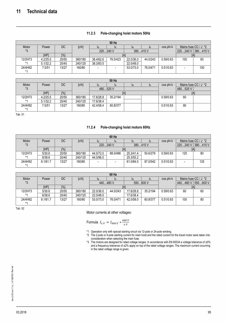
11 Technical data
03.2018 95
ba-o
.2.6
.0-u
s-1.
1-y
| A
1186
7501
Rev
AA
11.2.3 Pole-changing hoist motors 50Hz
50 Hz
Motor *3
Power DC [c/h] IN IK IN IK cos phi k Mains fuse CC / J *2
220…240 V 380…415 V 220…240 V 380…415 V
[HP] [%] [A] [A]
12/2H73 *1
4.2/25.5 20/50 360/180 38.4/62.6 76.5/423 22.0/36.0 44.0/243 0.59/0.63 100 60
5.1/32.2 20/40 240/120 38.3/83.5 22.0/48.0
24/4H92 *1
7.5/51 13/27 160/80 - - 53.0/73.0 76.0/471 0.51/0.63 - 100
50 Hz
Motor *3
Power DC [c/h] IN IK IN IK cos phi k Mains fuse CC / J *2
480…525 V 480…525 V
[HP] [%] [A] [A]
12/2H73 *1
4.2/25.5 20/50 360/180 17.6/28.8 35.2/194 0.59/0.63 60
5.1/32.2 20/40 240/120 17.6/38.4
24/4H92 *1
7.5/51 13/27 160/80 42.4/58.4 60.8/377 0.51/0.63 80
Tab. 51
11.2.4 Pole-changing hoist motors 60Hz
60 Hz
Motor *3
Power DC [c/h] IN IK IN IK cos phi k Mains fuse CC / J *2
220…240 V 380…415 V 220…240 V 380…415 V
[HP] [%] [A] [A]
12/2H73 *1
5/30.6 20/50 360/180 44.0/72.0 88.0/486 25.3/41.4 50.6/279 0.59/0.63 125 80
6/38.6 20/40 240/120 44.0/96.0 25.3/55.2
24/4H92 *1
9.1/61.7 13/27 160/80 - - 61.0/84.0 87.0/542 0.51/0.63 - 125
60 Hz
Motor *3
Power DC [c/h] IN IK IN IK cos phi k Mains fuse CC / J *2
440…480 V 550…600 V 440…480 V 550…600 V
[HP] [%] [A] [A]
12/2H73 *1
5/30.6 20/50 360/180 22.0/36.0 44.0/243 17.6/28.8 35.2/194 0.59/0.63 60 60
6/38.6 20/40 240/120 22.0/48.0 17.6/38.4
24/4H92 *1
9.1/61.7 13/27 160/80 53.0/73.0 76.0/471 42.0/58.0 60.8/377 0.51/0.63 100 80
Tab. 52
Motor currents at other voltages:
Formula 𝐼𝑥 𝑉 = 𝐼400 𝑉 ∗400 𝑉
𝑥 𝑉
*1 Operation only with special starting circuit via 12-pole or 24-pole winding. *2 The 2-pole or 4-pole starting current for main hoist and the rated current for the travel motor were taken into
consideration when selecting the main fuse. *3 The motors are designed for rated voltage ranges. In accordance with EN 60034 a voltage tolerance of ±5%
and a frequency tolerance of ±2% apply on top of the rated voltage ranges. The maximum current occurring in the rated voltage range is given.

11 Technical data
96 03.2018
ba-o
.2.6
.0-u
s-1.
1-y
| A
1186
7501
Rev
AA
11.2.5 Frequency-controlled hoist motors ../4H..-MF 100 Hz
100 Hz
Hoist motor *3
Power DC IN Mains fuse CC / J *1
380…415 V 500…525 V 660…690 V 380…415 V 500…525 V 660…690 V
[HP] [%] [A] [A]
4H33-MF 3.9 70 8.3 6.6 5.0 10 10 10
4.8 60 9.4 7.5 5.7
4H42-MF 4.8 70 9.3 7.4 5.6 15 10 10
6 60 10.7 8.6 6.5
4H62-MF 8 70 15.5 12.4 9.4 20 10 10
10.1 60 18.0 14.4 10.9
4H71-MF 10.1 70 18.0 14.4 10.9 25 15 15
12.1 60 21.0 17.0 12.7
4H72-MF 16.1 70 25.0 20.0 15.2 30 20 20
20.1 60 31.0 25.0 19.0
4H73-MF 24.1 70 34.0 27.2 20.6 50 30 30
30.8 60 42.0 34.0 26.0
4H81-MF 30.8 70 45.0 36.0 27.3 60 40 40
37.5 60 55.0 44.0 33.0
4H82-MF 37.5 70 57.0 45.6 34.5 80 50 50
46.9 60 64.0 51.0 39.0
Tab. 53
11.2.6 Frequency-controlled hoist motors ../4H..-MF 120 Hz
120 Hz
Hoist motor *3
Power DC IN Mains fuse CC / J *1
360…400 V 440…480 V 575…600 V 360…400 V 440…480 V 575…600 V
[HP] [%] [A] [A]
4H33-MF 4.7 70 9.9 8.2 6.6 10 10 10
5.8 60 11.3 9.3 7.4
4H42-MF 5.8 70 11.3 9.3 7.4 15 15 10
7.2 60 13.1 10.8 8.6
4H62-MF 9.7 70 20.6 17.0 13.6 20 20 10
12.1 60 23.0 19.0 15.2
4H71-MF 12.1 70 23.0 19.0 15.2 25 25 15
14.8 60 27.0 22.0 18.0
4H72-MF 18.8 70 31.5 26.0 20.8 30 30 20
24.1 60 38.0 31.0 25.0
4H73-MF 28.2 70 43.6 36.0 28.8 50 50 30
36.2 60 53.0 44.0 35.0
4H81-MF 37.5 70 55.7 46.0 36.8 60 60 40
45.6 60 68.0 56.0 45.0
4H82-MF 45.6 70 67.8 56.0 44.8 80 80 50
56.3 60 79.0 65.0 52.0
Tab. 54 *1 Protection not 100% with CC / J, we recommend additional semiconductor fuses. *3 The motors are designed for rated voltage ranges. In accordance with EN 60034 a voltage tolerance of ±5%
and a frequency tolerance of ±2% apply on top of the rated voltage ranges. If these are fully utilized, the permissible limit temperature of the temperature class may be exceeded by 10 K. The maximum current occurring in the rated voltage range is given.

11 Technical data
03.2018 97
ba-o
.2.6
.0-u
s-1.
1-y
| A
1186
7501
Rev
AA
11.2.7 Frequency-controlled hoist motors ../4HS.-MF 100 Hz
100 Hz
Hoist motor *3
Power DC IN Mains fuse CC / J *1
380…415 V 500…525 V 380…415 V 500…525 V
[HP] [%] [A] [A]
4HS3 3.9 80 8.3 6.6 15 10
4.8 70 9.3 7.4
6 60 10.7 8.6
4HS5 8 80 15.5 12.4 25 15
10.1 70 18.0 14.4
12.1 60 21.0 16.8
4HS7 16.1 80 24.0 19.2 50 25
20.1 70 28.0 22.4
24.1 60 34.0 27.2
4HS8 24.1 70 34.0 27.2 50 30
30.8 60 42.0 33.6
4HSA 37.5 70 57.0 45.6 80 50
46.9 60 64.0 51.2
Tab. 55
11.2.8 Frequency-controlled hoist motors ../4HS.-MF 120 Hz
120 Hz
Hoist motor *3
Power DC IN Mains fuse CC / J *1
440…480 V 575…600 V 440…480 V 575…600 V
[HP] [%] [A] [A]
4HS3 4.7 80 8.1 6.5 15 10
5.8 70 9.3 7.4
7.2 60 10.8 8.6
4HS5 9.7 70 17.0 13.6 25 15
12.1 60 19.0 15.2
14.8 60 22.0 17.6
4HS7 18.8 80 23.0 18.4 50 25
24.1 70 26.0 20.8
28.2 60 36.0 28.8
4HS8 28.2 70 36.0 28.8 50 30
36.2 60 44.0 35.2
4HSA 45.6 70 56.0 44.8 80 50
56.3 60 65.0 52.0
Tab. 56 *1 Protection not 100% with CC / J, we recommend additional semiconductor fuses. *3 The motors are designed for rated voltage ranges. In accordance with EN 60034 a voltage tolerance of ±5%
and a frequency tolerance of ±2% apply on top of the rated voltage ranges. If these are fully utilized, the permissible limit temperature of the temperature class may be exceeded by 10 K. The maximum current occurring in the rated voltage range is given.

11 Technical data
98 03.2018
ba-o
.2.6
.0-u
s-1.
1-y
| A
1186
7501
Rev
AA
11.3 Cable cross sections and lengths of supply cable
11.3.1 Cable cross sections and lengths of supply cable for pole-changing hoist motors …-MF
1 2 3 4 5 6 7
Hoist motor type
Stationary Hoist Hoist/crane Hoist Rising mains max. 33 ft
Crane Crane
Fixed installation in
PVC conduit Fixed installation in
PVC conduit Festoon cable in free air as flexible PVC-
sheathed cable
Fixed installation in PVC conduit
Festoon cable in free air as flexible PVC-sheathed cable
Festoon cable in free air as flexible PVC-sheathed cable
Power supply to hoist Power supply to in-feed
(customer’s cable to beginning of rising
mains)
From end of rising mains to hoist
From main isolator to end
of rising mains
From end of rising mains along crane
runway to crane control
Power supply along crane bridge to hoist
∆ U ≤ 5% ∆ U ≤ 1% ∆ U ≤ 4% (4+5) ∆ U ≤ 2.5%
∆ U ≤ 1.5% (5+6)
50 Hz 380-415 V 500-525 V 380-415 V 500-525 V 380-415 V 500-525 V 400 V 500 V 380-415 V 500-525 V 380-415 V 500-525 V
S L1 S L1 S L2 S L2 S L3 S L3 S S S L4 S L4 S L5 S L5
AWG [ft] AWG [ft] AWG [ft] AWG [ft] AWG [ft] AWG [ft] AWG AWG AWG [ft] AWG [ft] AWG [ft] AWG [ft]
12/2H33 12 212 14 208 10 67 12 66 12 149 14 146 10 12 8 109 10 106 12 106 14 104
12/2H42 10 288 12 283 8 92 10 90 10 210 12 206 8 10 8 104 10 102 10 144 12 141
12/2H62 8 273 10 268 6 87 8 85 8 198 10 194 6 8 6 97 8 95 8 136 10 134
12/2H71 8 273 10 268 6 87 8 85 8 198 10 194 6 8 6 97 8 95 8 136 10 134
12/2H72 6 290 8 285 4 92 6 91 6 211 8 207 4 6 4 105 6 103 6 145 8 142
12/2H91 4 257 6 252 2 82 4 80 4 185 6 181 2 4 2 90 4 88 4 128 6 126
60 Hz 440-480 V 575-600 V 440-480 V 575-600 V 440-480 V 575-600 V 460 V 575 V 440-480 V 575-600 V 440-480 V 575-600 V
12/2H33 12 239 14 235 10 76 12 75 12 171 14 167 10 12 10 81 12 79 12 120 14 118
12/2H42 10 322 12 317 8 102 10 101 12 149 14 146 8 10 10 76 12 74 12 101 14 100
12/2H62 8 334 10 328 6 106 8 104 10 155 12 152 6 8 8 79 10 78 10 105 12 103
12/2H71 8 334 10 328 6 106 8 104 10 155 12 152 6 8 8 79 10 78 10 105 12 103
12/2H72 6 362 8 356 4 115 6 113 8 169 10 166 4 6 6 88 8 86 8 114 10 112
12/2H91 4 295 6 290 2 94 4 92 6 136 8 133 2 4 4 68 6 66 4 148 6 145
Tab. 57
11.3.2 Cable cross sections and lengths of supply cable for pole-changing hoist motors
1 2 3 4 5 6 7
Hoist motor type
Stationary Hoist Hoist/crane Hoist/ Rising mains max. 33 ft
Crane Crane
Fixed installation in
PVC conduit Fixed installation in
PVC conduit Festoon cable in free air as flexible PVC-
sheathed cable
Fixed installation in PVC conduit
Festoon cable in free air as flexible PVC-sheathed cable
Festoon cable in free air as flexible PVC-sheathed cable
Power supply to hoist Power supply to in-feed
(customer’s cable to beginning of rising
mains)
From end of rising mains to hoist
From main isolator to end
of rising mains
From end of rising mains along crane
runway to crane control
Power supply along crane bridge to hoist
∆ U ≤ 5% ∆ U ≤ 1% ∆ U ≤ 4% (4+5) ∆ U ≤ 2.5%
∆ U ≤ 1.5% (5+6)
50 Hz 380-415 V 480-525 V 380-415 V 480-525 V 380-415 V 480-525 V 400 V 500 V 380-415 V 480-525 V 380-415 V 480-525 V
S L1 S L1 S L2 S L2 S L3 S L3 S S S L4 S L4 S L5 S L5
AWG [ft] AWG [ft] AWG [ft] AWG [ft] AWG [ft] AWG [ft] AWG AWG AWG [ft] AWG [ft] AWG [ft] AWG [ft]
12/2H73 6 185 8 181 4 59 6 58 6 135 8 132 2 4 4 67 6 66 6 92 8 91
24/4H92 4 153 6 150 1 61 2 76 4 112 6 110 -1 1 1 71 2 88 2 121 4 119
60 Hz 440-480 V 550-600 V 440-480 V 550-600 V 440-480 V 550-600 V 460 V 575 V 440-480 V 550-600 V 440-480 V 550-600 V
12/2H73 6 212 8 209 4 68 6 66 8 99 10 97 2 4 4 81 6 79 6 106 8 104
24/4H92 4 176 6 172 1 70 2 87 4 130 6 128 -1 1 1 85 4 66 4 88 6 86
Tab. 58
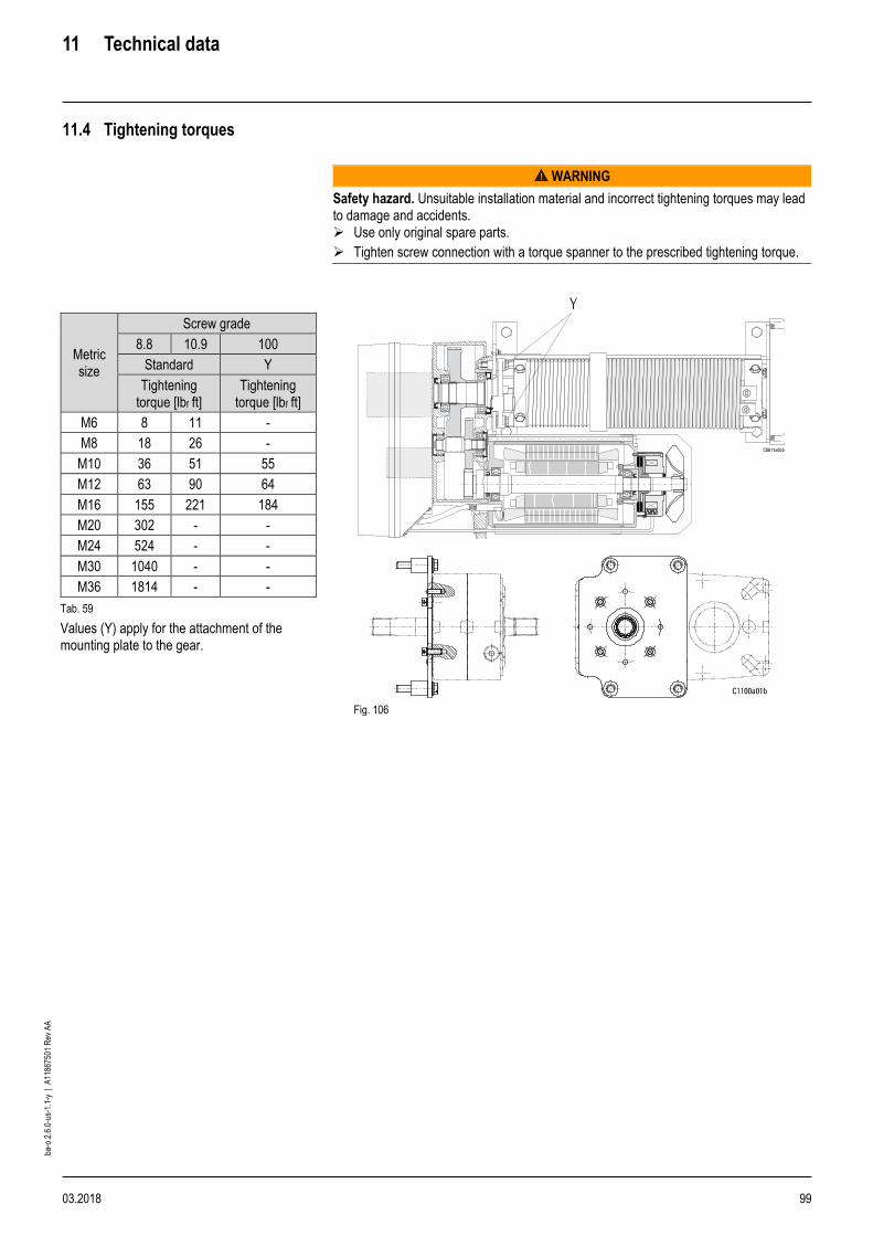
11 Technical data
03.2018 99
ba-o
.2.6
.0-u
s-1.
1-y
| A
1186
7501
Rev
AA
11.4 Tightening torques
WARNING
Safety hazard. Unsuitable installation material and incorrect tightening torques may lead to damage and accidents. ➢ Use only original spare parts.
➢ Tighten screw connection with a torque spanner to the prescribed tightening torque.
Metric size
Screw grade
8.8 10.9 100
Standard Y
Tightening torque [lbf ft]
Tightening torque [lbf ft]
M6 8 11 -
M8 18 26 -
M10 36 51 55
M12 63 90 64
M16 155 221 184
M20 302 - -
M24 524 - -
M30 1040 - -
M36 1814 - -
Tab. 59
Values (Y) apply for the attachment of the mounting plate to the gear.
Fig. 106
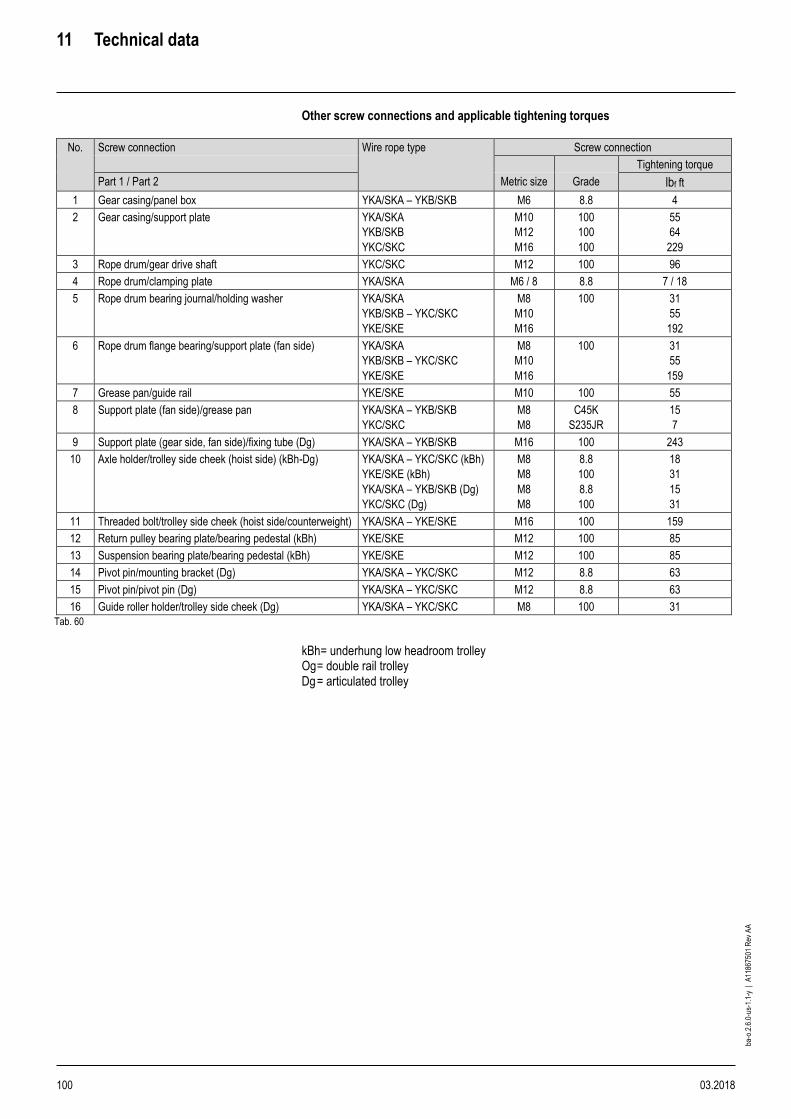
11 Technical data
100 03.2018
ba-o
.2.6
.0-u
s-1.
1-y
| A
1186
7501
Rev
AA
Other screw connections and applicable tightening torques
No. Screw connection Wire rope type Screw connection
Tightening torque
Part 1 / Part 2 Metric size Grade lbf ft
1 Gear casing/panel box YKA/SKA – YKB/SKB M6 8.8 4
2 Gear casing/support plate YKA/SKA
YKB/SKB
YKC/SKC
M10
M12
M16
100
100
100
55
64
229
3 Rope drum/gear drive shaft YKC/SKC M12 100 96
4 Rope drum/clamping plate YKA/SKA M6 / 8 8.8 7 / 18
5 Rope drum bearing journal/holding washer YKA/SKA
YKB/SKB – YKC/SKC
YKE/SKE
M8
M10
M16
100 31
55
192
6 Rope drum flange bearing/support plate (fan side) YKA/SKA
YKB/SKB – YKC/SKC
YKE/SKE
M8
M10
M16
100 31
55
159
7 Grease pan/guide rail YKE/SKE M10 100 55
8 Support plate (fan side)/grease pan YKA/SKA – YKB/SKB
YKC/SKC
M8
M8
C45K
S235JR
15
7
9 Support plate (gear side, fan side)/fixing tube (Dg) YKA/SKA – YKB/SKB M16 100 243
10 Axle holder/trolley side cheek (hoist side) (kBh-Dg) YKA/SKA – YKC/SKC (kBh)
YKE/SKE (kBh)
YKA/SKA – YKB/SKB (Dg)
YKC/SKC (Dg)
M8
M8
M8
M8
8.8
100
8.8
100
18
31
15
31
11 Threaded bolt/trolley side cheek (hoist side/counterweight) YKA/SKA – YKE/SKE M16 100 159
12 Return pulley bearing plate/bearing pedestal (kBh) YKE/SKE M12 100 85
13 Suspension bearing plate/bearing pedestal (kBh) YKE/SKE M12 100 85
14 Pivot pin/mounting bracket (Dg) YKA/SKA – YKC/SKC M12 8.8 63
15 Pivot pin/pivot pin (Dg) YKA/SKA – YKC/SKC M12 8.8 63
16 Guide roller holder/trolley side cheek (Dg) YKA/SKA – YKC/SKC M8 100 31
Tab. 60
kBh= underhung low headroom trolley Og = double rail trolley Dg = articulated trolley
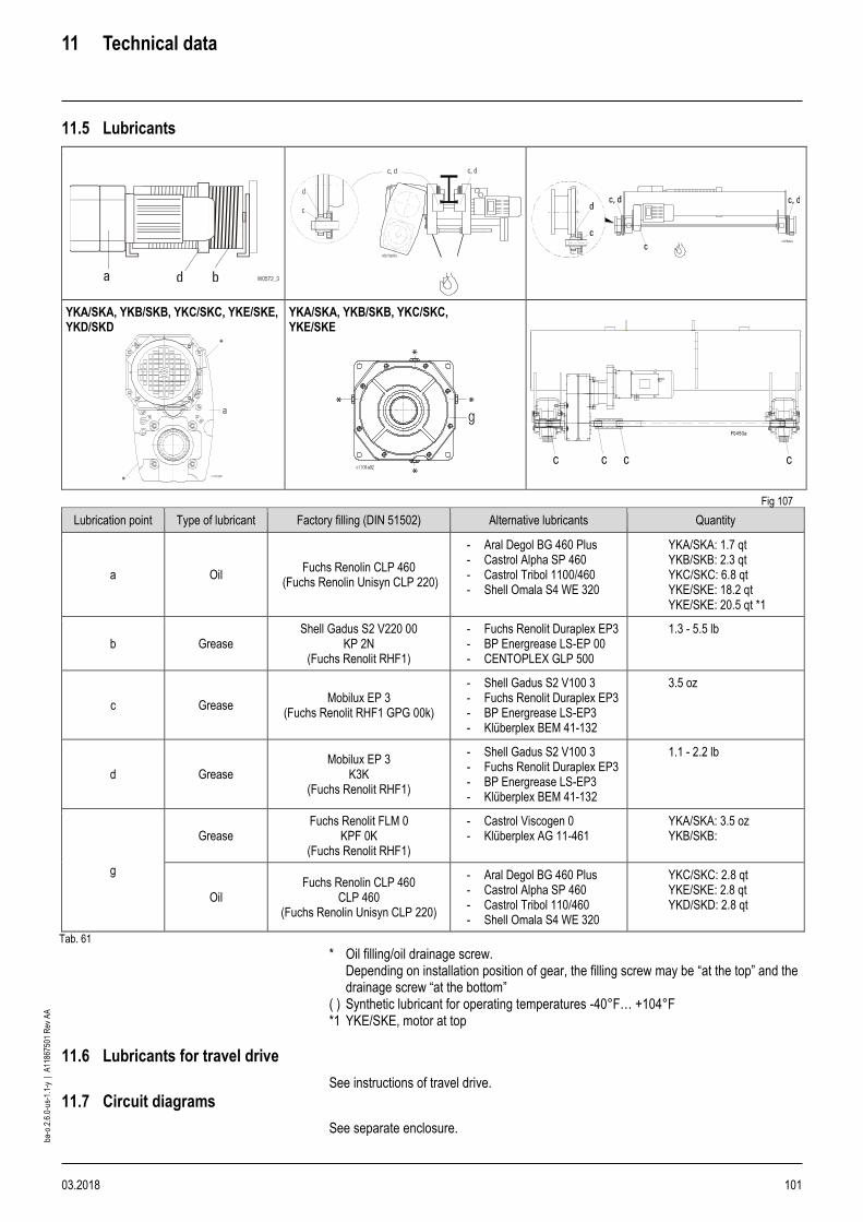
11 Technical data
03.2018 101
ba-o
.2.6
.0-u
s-1.
1-y
| A
1186
7501
Rev
AA
11.5 Lubricants
YKA/SKA, YKB/SKB, YKC/SKC, YKE/SKE, YKD/SKD
YKA/SKA, YKB/SKB, YKC/SKC, YKE/SKE
Fig 107
Lubrication point Type of lubricant Factory filling (DIN 51502) Alternative lubricants Quantity
a Oil Fuchs Renolin CLP 460
(Fuchs Renolin Unisyn CLP 220)
- Aral Degol BG 460 Plus - Castrol Alpha SP 460 - Castrol Tribol 1100/460 - Shell Omala S4 WE 320
YKA/SKA: 1.7 qt YKB/SKB: 2.3 qt YKC/SKC: 6.8 qt YKE/SKE: 18.2 qt YKE/SKE: 20.5 qt *1
b Grease Shell Gadus S2 V220 00
KP 2N (Fuchs Renolit RHF1)
- Fuchs Renolit Duraplex EP3 - BP Energrease LS-EP 00 - CENTOPLEX GLP 500
1.3 - 5.5 lb
c Grease Mobilux EP 3
(Fuchs Renolit RHF1 GPG 00k)
- Shell Gadus S2 V100 3 - Fuchs Renolit Duraplex EP3 - BP Energrease LS-EP3 - Klüberplex BEM 41-132
3.5 oz
d Grease Mobilux EP 3
K3K (Fuchs Renolit RHF1)
- Shell Gadus S2 V100 3 - Fuchs Renolit Duraplex EP3 - BP Energrease LS-EP3 - Klüberplex BEM 41-132
1.1 - 2.2 lb
g
Grease Fuchs Renolit FLM 0
KPF 0K (Fuchs Renolit RHF1)
- Castrol Viscogen 0 - Klüberplex AG 11-461
YKA/SKA: 3.5 oz YKB/SKB:
Oil Fuchs Renolin CLP 460
CLP 460 (Fuchs Renolin Unisyn CLP 220)
- Aral Degol BG 460 Plus - Castrol Alpha SP 460 - Castrol Tribol 110/460 - Shell Omala S4 WE 320
YKC/SKC: 2.8 qt YKE/SKE: 2.8 qt YKD/SKD: 2.8 qt
Tab. 61
* Oil filling/oil drainage screw. Depending on installation position of gear, the filling screw may be “at the top” and the drainage screw “at the bottom”
( ) Synthetic lubricant for operating temperatures -40°F… +104°F *1 YKE/SKE, motor at top
11.6 Lubricants for travel drive
See instructions of travel drive.
11.7 Circuit diagrams
See separate enclosure.
c c c
F0450a
c

Prin
ted
in U
SA
ba-
o.2.
6.0-
us-1
.1-y
| A
1186
7501
Rev
AA
WARRANTY LIMITATION OF WARRANTIES, REMEDIES AND DAMAGES
INDEMNIFICATION AND SAFE OPERATION Buyer shall comply with and require its employees to comply with directions set forth in instructions and manuals furnished by Seller and shall use and require its employees to follow such instructions and manuals and to use reasonable care in the use and maintenance of the goods. Buyer shall not remove or permit anyone to remove any warning or instruction signs on the goods. In the event of personal injury or damage to property or business arising from the use of the goods, Buyer shall within 48 hours thereafter give Seller written notice of such injury or damage. Buyer shall cooperate with Seller in investigating any such injury or damage and in the defense of any claims arising therefrom. If Buyer fails to comply with this section or if any injury or damage is caused, in whole or in part, by Buyer’s failure to comply with applicable federal or state safety requirements, Buyer shall indemnify and hold Seller harmless against any claims, loss or expense for injury or damage arising from the use of the goods. CMCO Warranty (HOISTS)
A. Columbus McKinnon Corporation (“Seller”) warrants to the original end user (“Buyer”) that: (a) for a period of one (1) year from the date of Seller’s delivery of the goods (collectively, the “Goods”) to the carrier, the electrical components of the Goods will be free from defects in workmanship and materials; and (b) for a period of three (3) years from the date of Seller’s delivery of the goods (collectively, the “Goods”) to the carrier, the mechanical components of the Goods will be free from defects in workmanship and materials.
B. IN THE EVENT OF ANY BREACH OF SUCH WARRANTY, SELLER’S SOLE OBLIGATION SHALL BE EXCLUSIVELY LIMITED TO, AT THE OPTION OF SELLER, REPAIR OR REPLACEMENT, F.O.B. SELLER’S POINT OF SHIPMENT, OF ANY GOODS THAT SELLER DETERMINES TO HAVE BEEN DEFECTIVE OR, IF SELLER DETERMINES THAT SUCH REPAIR OR REPLACEMENT IS NOT FEASIBLE, TO A REFUND OF THE PURCHASE PRICE UPON RETURN OF THE GOODS TO SELLER. NO CLAIM AGAINST SELLER FOR ANY BREACH OF (i) SUCH WARRANTY WITH RESPECT TO THE ELECTRICAL COMPONENTS OF ANY GOOD SHALL BE VALID OR ENFORCEABLE UNLESS BUYER’S WRITTEN NOTICE THEREOF IS RECEIVED BY SELLER WITHIN ONE (1) YEAR FROM THE DATE OF SELLER’S DELIVERY TO THE CARRIER AND (ii) SUCH WARRANTY WITH RESPECT TO THE MECHANICAL COMPONENTS OF ANY GOOD SHALL BE VALID OR ENFORCEABLE UNLESS BUYER’S WRITTEN NOTICE THEREOF IS RECEIVED BY SELLER WITHIN ONE (1) YEAR FROM THE DATE THE DATE ANY ALLEGED CLAIM ACCRUES. EXCEPT FOR THE WARRANTY SET FORTH ABOVE, SELLER MAKES NO OTHER WARRANTIES WITH RESPECT TO THE GOODS, WHETHER EXPRESSED OR IMPLIED, INCLUDING ANY WARRANTIES OF MERCHANTABILITY, FITNESS FOR A PARTICULAR PURPOSE, QUALITY AND/OR THOSE ARISING BY STATUTE OR OTHERWISE BY LAW OR FROM ANY COURSE OF DEALING OR USE OF TRADE, ALL OF WHICH ARE HEREBY EXPRESSLY DISCLAIMED.
C. IN NO EVENT SHALL SELLER BE LIABLE TO BUYER OR ANY THIRD
PARTY WITH RESPECT TO ANY GOOD, WHETHER IN CONTRACT,
TORT OR OTHER THEORY OF LAW, FOR LOSS OF PROFITS OR LOSS
OF USE, OR FOR ANY INCIDENTAL, CONSEQUENTIAL, SPECIAL,
DIRECT OR INDIRECT DAMAGES, HOWSOEVER CAUSED. SELLER’S
MAXIMUM LIABILITY TO BUYER WITH RESPECT TO THE GOODS SHALL
IN NO EVENT EXCEED THE PRICE PAID BY BUYER FOR THE GOODS
THAT ARE THE SUBJECT OF THE APPLICABLE CLAIM.
D. Seller shall not be liable for any damage, injury or loss arising out of the use
of the Goods if, prior to such damage, injury or loss, such Goods are: (1)
damaged or misused following Seller’s delivery to the carrier; (2) not maintained,
inspected, or used in compliance with applicable law and Seller’s written
instructions and recommendations; or (3) installed, repaired, altered or modified
(a) with any part or accessory other than those supplied by Seller or (b) without
compliance with such laws, instructions or recommendations.
E. This warranty is limited and provided only to the original end user. Each
Good must be registered within sixty (60) days of receipt of each
product to establish eligibility. Please register at www.cmworks.com/hoist-
warranty-registration or submit registration card via US mail.
F. Any action against Seller for breach of warranty, negligence or otherwise in
connection with the electrical components of any Good must be commenced
by Buyer within one (1) year after: (a) the date any alleged claim accrues; or
(b) the date of delivery of the Goods to Buyer, whichever is earlier. Any action
against Seller for breach of warranty, negligence or otherwise in connection
with the mechanical components of any Good must be commenced by Buyer
within one (1) year after the date any alleged claim accrues.
G. This warranty is contingent upon Buyer’s proper maintenance and care of the
Goods, and does not extend to normal wear and tear. Seller reserves the
right, at its option, to void this warranty in the event of Buyer’s use with the
Goods of parts or accessories other than those supplied by Seller.
Alterations or modifications of equipment and use of non-factory repair parts can lead to dangerous operation and injury.
TO AVOID INJURY: • Do not alter or modify equipment. • Do use only factory replacement parts.
USA: Ph: (800) 888.0985 • (716) 689.5400 • Fax: (716) 689.5644 • www.cmworks.com
CANADA: Ph: (877) 264.6478 • Fax: (877) 264.6477 • www.cmworks.com