Operation & Instructions Manual SA 3 - SA 100 SAR 3 - · PDF filepersonnel must be thoroughly...
20
Operation & Instructions Manual SAR 3 - SAR 100 SA 3 - SA 100
Transcript of Operation & Instructions Manual SA 3 - SA 100 SAR 3 - · PDF filepersonnel must be thoroughly...

Regd. Office & Works :38-A & 39-B, II Phase, Peenya Industrial AreaBangalore - 560 058.Ph : 080-28394366 Fax: 080-28392809E-mail : [email protected]
Delhi Branch:
Sector - 62, Noida - 201 301Mb: 93111 95850 (Veeresh), 92120 39339 (Ragesh)E-mail : [email protected]
1310, Tower 'A', Corenthum Complex
Pune Branch: 712, 713, Bldg. No. 1,
Ph : 020 - 25410465 Telefax: 020 - 25443186E-mail : [email protected]
"Siddharth Towers"Kothrud, Pune - 411 038.
DD/MN-001 ISSUE 7/13
All auma actuators are 100% tested and factory checked. Actuators are supplied ready for service. Most of the actuators are supplied to valve manufacturers for mounting to valves. It is usual for the valve manufacturer to set the switches and test the motorized valve.
Special care should be taken when commissioning. Wrong connection or faulty control wiring may result in damage to the motorized valve.
In case the actuators will not be mounted or commissioned for a long period, take care for adequate (dry) storage, refer to our instruction sheet “Transport, Storage and Commissioning of auma - actuators”.
Operation & Instructions Manual
SAR 3 - SAR 100
SA 3 - SA 100

Warnings and notes
Failure to observe the warnings and notes may lead to serious injuries or damage. Qualified personnel must be thoroughly familiar with all warnings and notes in these operation instructions.
Correct transport, proper storage, mounting and installation, as well as careful commissioning are essential to ensure a trouble-free and safe operation.
The following references draw special attention to safety-relevant procedures in these operation instructions. Each is marked by the appropriate pictograph.
This pictograph means: Note!
“Note” marks activities or procedures which have major influence on the correct operation.
Non-observance of these notes may lead to consequential damage.
This pictograph means : Warning!“Warning” marks activities or procedures which, if not carried out correctly can affect the safety of persons or material.
Only original AUMA spare parts should be used for the proper functioning of the equipments. Failure to use original spare parts voids the warranty and exempts AUMA from any liability.
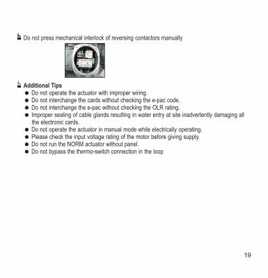
Do not press mechanical interlock of reversing contactors manually
Additional Tips= Do not operate the actuator with improper wiring.= Do not interchange the cards without checking the e-pac code.= Do not interchange the e-pac without checking the OLR rating.= Improper sealing of cable glands resulting in water entry at site inadvertently damaging all
the electronic cards.= Do not operate the actuator in manual mode while electrically operating.= Please check the input voltage rating of the motor before giving supply.= Do not run the NORM actuator without panel.= Do not bypass the thermo-switch connection in the loop
2 19

Do’s and Don’t’s - Troubleshooting tips
Setting of Limit switches:
Improper methods of declutch mechanism leading to premature failure of tripping arm
Re - set torque by loosening the adjustment screw
Improper tightening of covers or missing of o-rings during fitment
In the events of interchangeability check for the e-pac wiring diagram number
Transport and Storage
Transport:
= Transport to the place of Installation (till the last destination)= Avoid packages from exposing to open atmospheres during transit= Protect against rains
Storage:
= Store in well ventilated and dry rooms= Protect against humidity from floor by storage on wooden frame, on pallets, in cage boxes or on shelves= Cover actuators with plastic foil to protect against dust and dirt etc.= Protect suitably against mechanical damages= During long time storage, protect bright surfaces especially output drive parts and
mounting surface by applying long life corrosion protection agent. Also check once in six months for corrosion. If corrosion has started, clean and apply corrosion protection agent.
18 3
(7)
(8)
(9)
(1)
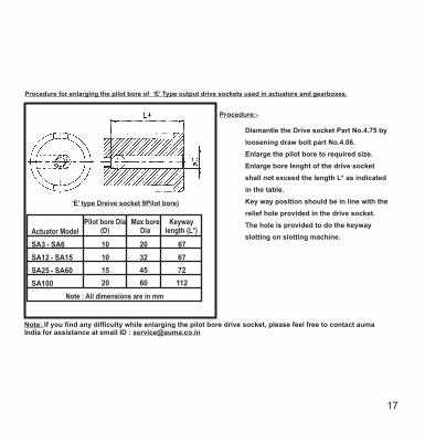
Procedure for enlarging the pilot bore of ‘E’ Type output drive sockets used in actuators and gearboxes.
Note: If you find any difficulty while enlarging the pilot bore drive socket, please feel free to contact aumaIndia for assistance at email ID : [email protected]
Dismantle the Drive socket Part No.4.75 by
loosening draw bolt part No.4.06.
Enlarge the pilot bore to required size.
Enlarge bore lenght of the drive socket
shall not exceed the length L* as indicated
in the table.
Key way position should be in line with the
relief hole provided in the drive socket.
The hole is provided to do the keyway
slotting on slotting machine.
Procedure:-
‘E’ type Dreive socket 9Pilot bore)
10 20 67
10 32 67
15 45 72
20 60 112
Actuator ModelPilot bore Dia
(D)Max bore
DiaKeyway
length (L*)
-
-
-
SA6S
S
S
S
S
A
A
A
A
A
3
12
25
15
60
SA100
Note : All dimensions are in mm
4 17

T
he
rmo
sw
itch
es a
re p
rovid
ed
to
pro
tect
Mo
tor
win
din
gs.
Th
ese
sh
ou
ld b
e c
on
ne
cte
d in
pa
ne
l co
ntr
ol cir
cu
it (
Re
fer
Te
rmin
al P
lan
), e
lse
ou
r w
arr
an
ty is v
oid
.
CA
UT
ION
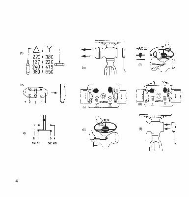
1. Electric connection
For 3 phase AC - motors:
Check whether terminal links are fitted to suit type of motor and power supply (fig.1).Connect wires R-S-T to terminal pins U -V -W (fig. 2), for flame proof 1 1 1
enclosure at clip-on terminals.
For single - phase or DC - motors, see instructions in terminal compartment.
Connect control wires according to the wiring diagram. Terminal plan is inside the terminal compartment.
Note : The two circuits of each switch (fig. 3) are suitable only for the same potential.
2. Remove cover at switch compartment (fig.4) Check whether limit-switch has tripped (fig.5) Valve completely closed : WSR tripped Valve completely opened : WOL tripped
3. Engage manual drive :Push declutch lever as indicated by arrow (fig. 6). If resistance is felt, turn handwheel slowly while lever is pressed till manual drive engages.
4. Operate valve to intermediate position manually (fig. 7) Direction OPEN ( ) turn handwheel anti-clockwise. Direction CLOSED ( ) turn handwheel clockwise. Switch cam at (Z) or (O) should rotate 90° and release the switch (fig. 8) if set properly.
5. Ensure sealing faces at control plug are clean and check whether O-ring is ok. Apply thin film of non - acid grease to sealing faces, then replace plug cover (fig. 9).
16 5

6 15
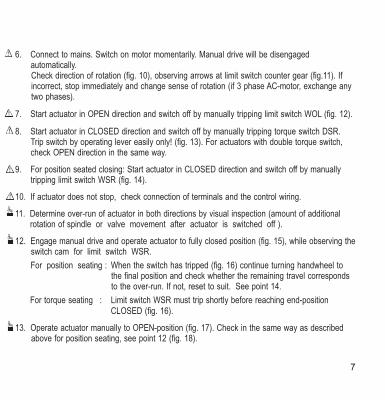
6. Connect to mains. Switch on motor momentarily. Manual drive will be disengaged automatically. Check direction of rotation (fig. 10), observing arrows at limit switch counter gear (fig.11). If incorrect, stop immediately and change sense of rotation (if 3 phase AC-motor, exchange any two phases).
7. Start actuator in OPEN direction and switch off by manually tripping limit switch WOL (fig. 12).
8. Start actuator in CLOSED direction and switch off by manually tripping torque switch DSR. Trip switch by operating lever easily only! (fig. 13). For actuators with double torque switch, check OPEN direction in the same way.
9. For position seated closing: Start actuator in CLOSED direction and switch off by manually tripping limit switch WSR (fig. 14).
10. If actuator does not stop, check connection of terminals and the control wiring.
11. Determine over-run of actuator in both directions by visual inspection (amount of additional rotation of spindle or valve movement after actuator is switched off ).
12. Engage manual drive and operate actuator to fully closed position (fig. 15), while observing the switch cam for limit switch WSR.
For position seating : When the switch has tripped (fig. 16) continue turning handwheel to the final position and check whether the remaining travel corresponds to the over-run. If not, reset to suit. See point 14.
For torque seating : Limit switch WSR must trip shortly before reaching end-position CLOSED (fig. 16).
13. Operate actuator manually to OPEN-position (fig. 17). Check in the same way as described above for position seating, see point 12 (fig. 18).
14 7

13
8
46
8
3
4
5
6
7
8
21
23
24
25
26
27
29
30
36
37
01
02
03
04
05
06
07
010
013
014
017
021
022
023
024
025
027
028
041
043
045
047
048
052
058
2.1
2.2
2.3
2.4
2.6
2.7
2.8
2.02
2.05
2.06
2.09
2.010
2.011
2.012
2.013
4.4
4.7
4.8
4.11
4.12
4.13
4.21
4.22
4.23
4.24
4.75
4.05
4.06
4.07
4.08
4.09
4.010
4.011
4.012
5.1
5.2
5.01
5.02
5.03
5.04
5.05
5.06
5.07
5.08
5.09
5.010
7.1
7.2
7.05
7.06
9.1
9.01
9.02
External bearing retainer
Internal bearing retainer
Declutch lever
Clutch roller pin, short
Clutch roller pin, long
Clutch fork assembly
Worm shaft assembly
Bearing flange
Hollow drive shaft
Compressing spring
Clutch Ring
Helical gear (SA 6 only)
Handwheel
Handwheel retainer
Pinion gear (Shaft assembly)
Compression spring
O-ring (Clutch roller pin)
O-ring (Declutch lever)
O-ring (drive assly. flanges)
O-ring (bearing retainer)
O-ring (Handwheel)
O-ring (Bearing flange)
O-ring (Switch comp. cover)
Quad ring
Oil seal
Oil seal
Ball bearing
Circlip
Circlip
Circlip
Circlip
Circlip
Snap ring
Lid
Blinker switch (SPST)
Spring washer
Lock washer
Lock washer
Fillister head screw
Support washer
Star washer
Dog drive sleeve (type C)
Thrust ring
Keyway drive sleeve (type B)
Drive socket (type E)
Stud bolt
Flat washer
Hexagon nut
Cap
Hexagon head bolt
Lock washer
Parallel key
Lock washer
Set screw
Grease nipple
Thrust bearing
Thrust bearing race
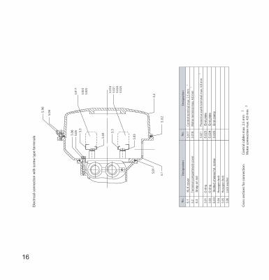
Terminal box cover
Terminal mounting plate
Pin carrier (control)
Socket carrier (control)
Plug pin (control)
Plug socket (control)
Fillister head screw
Lock washer
Conduit gland
Thrust washer
Seal ring
O-ring
Pin carrier (motor)
Socket carrier (motor)
Plug pin (motor)
Plug socket (motor)
Limit switch (SPDT)
Torque switch (SPDT)
Fillister head screw
Lock washer
Potentiometer *
Fillister head screw
Lock washer
Limit switch drive assembly
Limit switch counter gear
Torque switch drive assembly
Reduction gearing assembly
*state resistance when ordering
Motor pinion
Spur gear
Motor mounting flange
Shield
Worm gear
Motor
O-ring
O-ring
Hexagon head bolt
Lock washer
Flat washer
Hexagon head bolt
Lock washer
Fillister head screw
Lock washer
Indicator assembly
Indicator glass
Glass retaining ring
O-ring
Fillister head screw
Lock washer
Stem protection tube
Stub shaft (type D)
Mounting flange (type D & F)
Mounting flange (type A)
Stem nut (type A)
44.01
44.02
44.03
44.04
6.1
6.2
6.7
6.8
1
2
Gear box housing
Switch compartment cover
Spare Parts SA 3 - SAR 100SAR 3 - SAR 100
When placing orders for spare parts it is essential to mention order number, work’s number and type of the actuator
(refer to name plate). Parts with number in a circle, e.g. , will be supplied complete only.
PartNo.
Designation PartNo.
Designation PartNo.
Designation
Bearing locknut
Mounting flange (types B & C)
3.5
3.1
3.6
3.01
3.02
3.03
31
44
45
14
15
16
17
18
19
Declutch tripping arm
Retaining plate
Return spring
Spacer
Bushing
Retaining ring (SA 6 only)
9.1 Potentiometer with Drive Gears*
030
031
032
033
034
035
039
Hexagon head bolt
Hexagon head bolt
Thin shank hex head bolt
Counter sunk oval head screw
Hexagon head bolt
Fillister head screw
Parallel key
Optional Accessories:
Resistive Position Transmitter :
RWG 2002
RWG 1001
RWG 2002G
RWG 2002DG
Inductive Position Transmitter:
IWG 1002
IWG 1003
Power Supply Unit PS01
Electronic Positioner CU01

14. Resetting limit-switching:
— Operate valve away from end-position to account for over-run or to the desired switch tripping point.
— Push thrust bolt I inwards and turn (fig. 19). The bolt remains in this position.
— For CLOSED position turn spindle marked (Z), (for OPEN position spindle marked, O) slowly as indicated by arrow (fig. 19). Distinct "clicks" can be felt and heard. Continue
turning the spindle until the cam operates the switch. At this stage, the spindle should not "click" any more and should not be turned any further.
If inadvertently you override the tripping point, continue turning the spindle slowly in the same direction till the switch cam goes back to its original position. Repeat setting instructions as above described.
— Turn thrust bolt I till it snaps back into its original position by spring action.
15. Torque switching (fig. 20)If the actuator is switched off by torque switch over its travel before reaching an end-position, please check whether the valve stem is damaged or dirt adhering to it. If necessary, and with the valve maker’s consent, the setting of the tripping torque may be raised slightly.
16. Setting : Figures on the torque switch operating cam indicate the valves in Nm (1 mkp = 10 Nm. 1 lbsft. = 1.36 Nm).Loosen screw and turn the cam till the desired torque coincides with the arrow mark, then fasten lock-screw.
17. Immediately after start-up : Ensure sealing faces at cover and housing are clean. Check whether O-ring is correctly in position and apply a thin film of non-acid grease. Replace the cover and fasten with 4 screws (fig. 21).
18. Fasten control cover screws and tighten glands at conduit entries.
12 9

(23)
Setting of optional equipment
19. Mechanical position indicator : The two dials have a slip clutch for easy adjustment. At valve fully
closed, turn dial (CLOSED) till the arrow is in alignment with the mark on the show glass.
Operate valve into fully OPEN position and adjust dial marked (OPEN) till the arrow mark is in
alignment with the mark on the cover.
Note: The dial (CLOSED) must be held in position while adjusting dial (OPEN). (fig. 22).
20. Electric position transmitter
Through a reduction gearing (selected to suit turns required by valve travel) a potentiometer will be
driven. A suitable power supply unit supplies a low voltage current. The valve position can be read
on a remote instrument with a percentage scale.
21. Setting
Operate valve to the fully CLOSED position (= 0%). Set potentiometer to its starting position by 1turning the wiper ), which has a slip clutch (fig. 23).
Adjust the position meter to zero by trimming potentiometer in the power supply unit (fig. 24).
Operate valve to the fully OPEN position (= 100%). Adjust the position meter to max. range with
the help of the trimming potentiometer in the power supply unit (fig. 24). Check indication for both
end positions. If required, make slight re - adjustment.
1) applies only to open potentiometer as shown in figure 23.
10 11

14. Resetting limit-switching:
— Operate valve away from end-position to account for over-run or to the desired switch tripping point.
— Push thrust bolt I inwards and turn (fig. 19). The bolt remains in this position.
— For CLOSED position turn spindle marked (Z), (for OPEN position spindle marked, O) slowly as indicated by arrow (fig. 19). Distinct "clicks" can be felt and heard. Continue
turning the spindle until the cam operates the switch. At this stage, the spindle should not "click" any more and should not be turned any further.
If inadvertently you override the tripping point, continue turning the spindle slowly in the same direction till the switch cam goes back to its original position. Repeat setting instructions as above described.
— Turn thrust bolt I till it snaps back into its original position by spring action.
15. Torque switching (fig. 20)If the actuator is switched off by torque switch over its travel before reaching an end-position, please check whether the valve stem is damaged or dirt adhering to it. If necessary, and with the valve maker’s consent, the setting of the tripping torque may be raised slightly.
16. Setting : Figures on the torque switch operating cam indicate the valves in Nm (1 mkp = 10 Nm. 1 lbsft. = 1.36 Nm).Loosen screw and turn the cam till the desired torque coincides with the arrow mark, then fasten lock-screw.
17. Immediately after start-up : Ensure sealing faces at cover and housing are clean. Check whether O-ring is correctly in position and apply a thin film of non-acid grease. Replace the cover and fasten with 4 screws (fig. 21).
18. Fasten control cover screws and tighten glands at conduit entries.
12 9

13
8
46
8
3
4
5
6
7
8
21
23
24
25
26
27
29
30
36
37
01
02
03
04
05
06
07
010
013
014
017
021
022
023
024
025
027
028
041
043
045
047
048
052
058
2.1
2.2
2.3
2.4
2.6
2.7
2.8
2.02
2.05
2.06
2.09
2.010
2.011
2.012
2.013
4.4
4.7
4.8
4.11
4.12
4.13
4.21
4.22
4.23
4.24
4.75
4.05
4.06
4.07
4.08
4.09
4.010
4.011
4.012
5.1
5.2
5.01
5.02
5.03
5.04
5.05
5.06
5.07
5.08
5.09
5.010
7.1
7.2
7.05
7.06
9.1
9.01
9.02
External bearing retainer
Internal bearing retainer
Declutch lever
Clutch roller pin, short
Clutch roller pin, long
Clutch fork assembly
Worm shaft assembly
Bearing flange
Hollow drive shaft
Compressing spring
Clutch Ring
Helical gear (SA 6 only)
Handwheel
Handwheel retainer
Pinion gear (Shaft assembly)
Compression spring
O-ring (Clutch roller pin)
O-ring (Declutch lever)
O-ring (drive assly. flanges)
O-ring (bearing retainer)
O-ring (Handwheel)
O-ring (Bearing flange)
O-ring (Switch comp. cover)
Quad ring
Oil seal
Oil seal
Ball bearing
Circlip
Circlip
Circlip
Circlip
Circlip
Snap ring
Lid
Blinker switch (SPST)
Spring washer
Lock washer
Lock washer
Fillister head screw
Support washer
Star washer
Dog drive sleeve (type C)
Thrust ring
Keyway drive sleeve (type B)
Drive socket (type E)
Stud bolt
Flat washer
Hexagon nut
Cap
Hexagon head bolt
Lock washer
Parallel key
Lock washer
Set screw
Grease nipple
Thrust bearing
Thrust bearing race
Terminal box cover
Terminal mounting plate
Pin carrier (control)
Socket carrier (control)
Plug pin (control)
Plug socket (control)
Fillister head screw
Lock washer
Conduit gland
Thrust washer
Seal ring
O-ring
Pin carrier (motor)
Socket carrier (motor)
Plug pin (motor)
Plug socket (motor)
Limit switch (SPDT)
Torque switch (SPDT)
Fillister head screw
Lock washer
Potentiometer *
Fillister head screw
Lock washer
Limit switch drive assembly
Limit switch counter gear
Torque switch drive assembly
Reduction gearing assembly
*state resistance when ordering
Motor pinion
Spur gear
Motor mounting flange
Shield
Worm gear
Motor
O-ring
O-ring
Hexagon head bolt
Lock washer
Flat washer
Hexagon head bolt
Lock washer
Fillister head screw
Lock washer
Indicator assembly
Indicator glass
Glass retaining ring
O-ring
Fillister head screw
Lock washer
Stem protection tube
Stub shaft (type D)
Mounting flange (type D & F)
Mounting flange (type A)
Stem nut (type A)
44.01
44.02
44.03
44.04
6.1
6.2
6.7
6.8
1
2
Gear box housing
Switch compartment cover
Spare Parts SA 3 - SAR 100SAR 3 - SAR 100
When placing orders for spare parts it is essential to mention order number, work’s number and type of the actuator
(refer to name plate). Parts with number in a circle, e.g. , will be supplied complete only.
PartNo.
Designation PartNo.
Designation PartNo.
Designation
Bearing locknut
Mounting flange (types B & C)
3.5
3.1
3.6
3.01
3.02
3.03
31
44
45
14
15
16
17
18
19
Declutch tripping arm
Retaining plate
Return spring
Spacer
Bushing
Retaining ring (SA 6 only)
9.1 Potentiometer with Drive Gears*
030
031
032
033
034
035
039
Hexagon head bolt
Hexagon head bolt
Thin shank hex head bolt
Counter sunk oval head screw
Hexagon head bolt
Fillister head screw
Parallel key
Optional Accessories:
Resistive Position Transmitter :
RWG 2002
RWG 1001
RWG 2002G
RWG 2002DG
Inductive Position Transmitter:
IWG 1002
IWG 1003
Power Supply Unit PS01
Electronic Positioner CU01

6. Connect to mains. Switch on motor momentarily. Manual drive will be disengaged automatically. Check direction of rotation (fig. 10), observing arrows at limit switch counter gear (fig.11). If incorrect, stop immediately and change sense of rotation (if 3 phase AC-motor, exchange any two phases).
7. Start actuator in OPEN direction and switch off by manually tripping limit switch WOL (fig. 12).
8. Start actuator in CLOSED direction and switch off by manually tripping torque switch DSR. Trip switch by operating lever easily only! (fig. 13). For actuators with double torque switch, check OPEN direction in the same way.
9. For position seated closing: Start actuator in CLOSED direction and switch off by manually tripping limit switch WSR (fig. 14).
10. If actuator does not stop, check connection of terminals and the control wiring.
11. Determine over-run of actuator in both directions by visual inspection (amount of additional rotation of spindle or valve movement after actuator is switched off ).
12. Engage manual drive and operate actuator to fully closed position (fig. 15), while observing the switch cam for limit switch WSR.
For position seating : When the switch has tripped (fig. 16) continue turning handwheel to the final position and check whether the remaining travel corresponds to the over-run. If not, reset to suit. See point 14.
For torque seating : Limit switch WSR must trip shortly before reaching end-position CLOSED (fig. 16).
13. Operate actuator manually to OPEN-position (fig. 17). Check in the same way as described above for position seating, see point 12 (fig. 18).
14 7

6 15
Th
erm
o s
witch
es a
re p
rovid
ed
to
pro
tect
Mo
tor
win
din
gs.
Th
ese
sh
ou
ld b
e c
on
ne
cte
d in
pa
ne
l co
ntr
ol cir
cu
it (
Re
fer
Te
rmin
al P
lan
), e
lse
ou
r w
arr
an
ty is v
oid
.
CA
UT
ION
1. Electric connection
For 3 phase AC - motors:
Check whether terminal links are fitted to suit type of motor and power supply (fig.1).Connect wires R-S-T to terminal pins U -V -W (fig. 2), for flame proof 1 1 1
enclosure at clip-on terminals.
For single - phase or DC - motors, see instructions in terminal compartment.
Connect control wires according to the wiring diagram. Terminal plan is inside the terminal compartment.
Note : The two circuits of each switch (fig. 3) are suitable only for the same potential.
2. Remove cover at switch compartment (fig.4) Check whether limit-switch has tripped (fig.5) Valve completely closed : WSR tripped Valve completely opened : WOL tripped
3. Engage manual drive :Push declutch lever as indicated by arrow (fig. 6). If resistance is felt, turn handwheel slowly while lever is pressed till manual drive engages.
4. Operate valve to intermediate position manually (fig. 7) Direction OPEN ( ) turn handwheel anti-clockwise. Direction CLOSED ( ) turn handwheel clockwise. Switch cam at (Z) or (O) should rotate 90° and release the switch (fig. 8) if set properly.
5. Ensure sealing faces at control plug are clean and check whether O-ring is ok. Apply thin film of non - acid grease to sealing faces, then replace plug cover (fig. 9).
16 5
(7)
(8)
(9)
(1)
Procedure for enlarging the pilot bore of ‘E’ Type output drive sockets used in actuators and gearboxes.
Note: If you find any difficulty while enlarging the pilot bore drive socket, please feel free to contact aumaIndia for assistance at email ID : [email protected]
Dismantle the Drive socket Part No.4.75 by
loosening draw bolt part No.4.06.
Enlarge the pilot bore to required size.
Enlarge bore lenght of the drive socket
shall not exceed the length L* as indicated
in the table.
Key way position should be in line with the
relief hole provided in the drive socket.
The hole is provided to do the keyway
slotting on slotting machine.
Procedure:-
‘E’ type Dreive socket 9Pilot bore)
10 20 67
10 32 67
15 45 72
20 60 112
Actuator ModelPilot bore Dia
(D)Max bore
DiaKeyway
length (L*)
-
-
-
SA6S
S
S
S
S
A
A
A
A
A
3
12
25
15
60
SA100
Note : All dimensions are in mm
4 17

Do’s and Don’t’s - Troubleshooting tips
Setting of Limit switches:
Improper methods of declutch mechanism leading to premature failure of tripping arm
Re - set torque by loosening the adjustment screw
Improper tightening of covers or missing of o-rings during fitment
In the events of interchangeability check for the e-pac wiring diagram number
Transport and Storage
Transport:
= Transport to the place of Installation (till the last destination)= Avoid packages from exposing to open atmospheres during transit= Protect against rains
Storage:
= Store in well ventilated and dry rooms= Protect against humidity from floor by storage on wooden frame, on pallets, in cage boxes or on shelves= Cover actuators with plastic foil to protect against dust and dirt etc.= Protect suitably against mechanical damages= During long time storage, protect bright surfaces especially output drive parts and
mounting surface by applying long life corrosion protection agent. Also check once in six months for corrosion. If corrosion has started, clean and apply corrosion protection agent.
18 3
Warnings and notes
Failure to observe the warnings and notes may lead to serious injuries or damage. Qualified personnel must be thoroughly familiar with all warnings and notes in these operation instructions.
Correct transport, proper storage, mounting and installation, as well as careful commissioning are essential to ensure a trouble-free and safe operation.
The following references draw special attention to safety-relevant procedures in these operation instructions. Each is marked by the appropriate pictograph.
This pictograph means: Note!
“Note” marks activities or procedures which have major influence on the correct operation.
Non-observance of these notes may lead to consequential damage.
This pictograph means : Warning!“Warning” marks activities or procedures which, if not carried out correctly can affect the safety of persons or material.
Only original AUMA spare parts should be used for the proper functioning of the equipments. Failure to use original spare parts voids the warranty and exempts AUMA from any liability.
Do not press mechanical interlock of reversing contactors manually
Additional Tips= Do not operate the actuator with improper wiring.= Do not interchange the cards without checking the e-pac code.= Do not interchange the e-pac without checking the OLR rating.= Improper sealing of cable glands resulting in water entry at site inadvertently damaging all
the electronic cards.= Do not operate the actuator in manual mode while electrically operating.= Please check the input voltage rating of the motor before giving supply.= Do not run the NORM actuator without panel.= Do not bypass the thermo-switch connection in the loop
2 19

Regd. Office & Works :38-A & 39-B, II Phase, Peenya Industrial AreaBangalore - 560 058.Ph : 080-28394366 Fax: 080-28392809E-mail : [email protected]
Delhi Branch:
Sector - 62, Noida - 201 301Mb: 93111 95850 (Veeresh), 92120 39339 (Ragesh)E-mail : [email protected]
1310, Tower 'A', Corenthum Complex
Pune Branch: 712, 713, Bldg. No. 1,
Ph : 020 - 25410465 Telefax: 020 - 25443186E-mail : [email protected]
"Siddharth Towers"Kothrud, Pune - 411 038.
DD/MN-001 ISSUE 7/13
All auma actuators are 100% tested and factory checked. Actuators are supplied ready for service. Most of the actuators are supplied to valve manufacturers for mounting to valves. It is usual for the valve manufacturer to set the switches and test the motorized valve.
Special care should be taken when commissioning. Wrong connection or faulty control wiring may result in damage to the motorized valve.
In case the actuators will not be mounted or commissioned for a long period, take care for adequate (dry) storage, refer to our instruction sheet “Transport, Storage and Commissioning of auma - actuators”.
Operation & Instructions Manual
SAR 3 - SAR 100
SA 3 - SA 100