EasyCoder 501 SA Bar Code Label Printer - S&PSapps.intermec.com/downloads/eps_man/96055000.pdf ·...
117
EasyCoder 501 SA Bar Code Label Printer Installation & Operation P/N 1-960550-00 Edition 1 October 2001
Transcript of EasyCoder 501 SA Bar Code Label Printer - S&PSapps.intermec.com/downloads/eps_man/96055000.pdf ·...

EasyCoder 501 SABar Code Label Printer
Installation & Operation
P/N 1-960550-00Edition 1October 2001

Intermec EasyCoder 501 SA – Installation & Operation Ed. 1 1
Preface
Preface Table of Contents.................................................................................1 Copyright Information ........................................................................4 Trademarks ..........................................................................................4 FCC Notice (U.S.A.) ...........................................................................5 DOC Notice (Canada).........................................................................5 GS Notice (Germany) .........................................................................5 Declaration of Conformity (CE) ........................................................6
1. Introduction Models..................................................................................................7 Supplementing Manuals .....................................................................8 Safety Requirements ...........................................................................8 Product Labeling .................................................................................8
2. Installation Unpacking............................................................................................9 Front View .........................................................................................10 Rear View ..........................................................................................11 Media Compartment .........................................................................12 Print Unit............................................................................................14 Connections .......................................................................................15 • Power ..............................................................................................15 • Computer........................................................................................15 Controls and Indicators .....................................................................16 • Control Lamps ...............................................................................16 • Display............................................................................................16 • Keyboard ........................................................................................16 • Beeper.............................................................................................16
3. Starting Up Startup Files.......................................................................................17 Switching On the Printer ..................................................................18 Display Messages at Startup.............................................................18
4. Media Load Tear-Off (Straight-through) ..............................................................19 Cut-Off ..............................................................................................23 Peel-Off (Self-strip)...........................................................................28 Internal Batch Takeup.......................................................................33 External Supply .................................................................................38
5. Thermal Transfer Printing Ribbon Load ..................................................................................... 40
EasyCoder 501 SAInstallation & OperationEdition 1, October 2001Part No. 1-960550-00
Contents

Intermec EasyCoder 501 SA – Installation & Operation Ed. 12
Preface
Contents, cont.
6. Setting Up the Printer Description........................................................................................ 44 Default Setup .................................................................................... 44 Setup Parameters:..............................................................................45 • Contrast ..........................................................................................45 • Serial Communication: .................................................................45 - Baud rate ......................................................................................45 - Parity ............................................................................................46 - Character Length.........................................................................46 - Stop bits........................................................................................46 - Flow Control................................................................................46 - New Line......................................................................................48 • Detection: .......................................................................................48 - LSS Adjustment...........................................................................48 - Feed Adjustment..........................................................................49 • Service:...........................................................................................51 - Media Size ...................................................................................51 - Media Type..................................................................................55 - Print Defs .....................................................................................56 - Performance................................................................................ 60 - Memory Allocation.....................................................................61
7. Setup Mode Setting Up EasyCoder 501 SA .........................................................62 Navigating in Setup Mode ................................................................63 Setup Mode Overviews.................................................................... 64
8. Options Introduction........................................................................................66 Cutter..................................................................................................66 Memory Card Adapter......................................................................68 Liner Takeup Unit..............................................................................70 Internal Batch Takeup Guide............................................................70 Media Roll Retainer ..........................................................................70 External Media Guides .....................................................................70 Label Taken Sensor ...........................................................................71 Ribbon Save Device ..........................................................................72 Ribbon Low/Media Low Sensor Kit ...............................................74 Clear Door Panel ...............................................................................75 Interface Boards ................................................................................75
9. Troubleshooting Troubleshooting List..........................................................................76
10. Maintenance Printhead Cleaning............................................................................77 External Cleaning..............................................................................80 Cleaning the Cutter (option) .............................................................81

Intermec EasyCoder 501 SA – Installation & Operation Ed. 1 3
Preface
Contents, cont.
10. Maintenance, cont. Cleaning the Ribbon Save Device (option) .....................................82 Printhead Replacement .....................................................................83
11. Adjustments Label Stop Sensor..............................................................................84 Display Contrast ................................................................................89 Printhead Pressure............................................................................ 90
Appendix 1 Technical Data ...................................................................................91
Appendix 2 Media Specifi cations.........................................................................93 • Direct Thermal Media...................................................................93 • Thermal Transfer Media ...............................................................93 • Media Roll Size..............................................................................94 • Media:.............................................................................................95 - Non-Adhesive Strip.....................................................................95 - Self-Adhesive Strip......................................................................96 - Self-Adhesive Labels...................................................................97 - Tickets with Gap..........................................................................98 - Tickets with Black Mark.............................................................99 • Transfer Ribbons..........................................................................100
Appendix 3 CPU Board.......................................................................................101 • Accessing the CPU Board...........................................................101 • Safety Instructions.......................................................................102 • Potentiometers..............................................................................102
Appendix 4 Interfaces:.........................................................................................104 • Standard Interface "uart1:" .........................................................104 • Serial Interface Board (option) ...................................................111 • RS-422/485 Interface Board (option) ........................................113 • Parallel Interface Board (option) ................................................115 • Industrial Interface Board (option).............................................116

Intermec EasyCoder 501 SA – Installation & Operation Ed. 14
Preface
Information in this manual is subject to change without prior notice and does not represent a commitment on the part of Intermec Printer AB.
© Copyright Intermec Printer AB, 2001. All rights reserved. Published in Sweden.
EasyCoder, EasyLAN, Fingerprint, and LabelShop are registered trademarks of Intermec Technologies Corp. The word Intermec, the Intermec logo, InterDriver, PrintSet, and Duratherm are trademarks of Intermec Technologies Corp.Centronics is a registered trademark of Genicom Corporation.Microsoft is a registered trademark of Microsoft Corporation.Speedo is a trademark of Bitstream, Inc.Torx is a registered trademark of Camcar Division of Textron Inc.TrueType is a trademark of Apple Computer Inc.Unicode is a trademark of Unicode Inc.Windows is a trademark of Microsoft Corporation

Intermec EasyCoder 501 SA – Installation & Operation Ed. 1 5
Preface
FCC Notice (United States of America)
WARNINGThis equipment generates, uses, and can radiate radio frequency energy and if not installed and used in accordance with the instructions manual, may cause interference to radio communications. It has been tested and found to comply with the limits for a Class A computing device pursuant to Subpart J of Part 15 of FCC Rules, which are designed to provide reasonable protection against such interference when operated in a commercial environment. Operation of this equipment in a residential area is likely to cause interference in which case the user at his own expense will be required to take whatever measures may be required to correct the interference.
DOC Notice (Canada)
Canadian Dept. of CommunicationREGULATIONS COMPLIANCE (DOC-A)
This digital apparatus does not exceed the class A limits for radio noise emissions from a digital apparatus as set out in the radio interference regulations of the Canadian Department of Communication.
Ministère des Communications du CanadaCONFORMITE DE REGLEMENTS (DOC-A)
Le présent appareil numérique n’émet pas de bruits radio-électriques dépassant les limites applicables aux appareils numériques de classe A prescrites dans le règlement sur brouillage radioélectrique édicté par le Ministère des Communications du Canada.
GS Notice (Germany)
ALLGEMEINE VORSCHRIFTReparaturen oder sonstige Eingriffe, die sich nicht auf normale Bedienung der Maschine beziehen, dürfen ausschließlich nur von einem ausgebildeten, zuständigen Fachmann vorgenommen werden.

Intermec EasyCoder 501 SA – Installation & Operation Ed. 16
Preface
Declaration of ConformityWe,
Intermec Printer ABIdrottsvägen 10
Box 123S-431 22 Mölndal
Sweden
declare under our sole responsibility1 that the product
EasyCoder 501 SA
to which this declaration relatesis in conformity with the following standard
EN 60 950, 1992EN 50 081-1, 1992EN 55 022, Class BEN 50 082-2, 1995
ENV 50 140, 10 V/mENV 50 204, 10 V/mENV 50 141, 10 V/m
EN 61 000-4-2, 6 kV (Con), 8 kV (Air)EN 61000-4-4, 2 kV power lines, 1 kV signal lines
following the provisions of Directives
89/336/EEC and 73/23/EEC
Mölndal 1998-09-01
...................................................................Hans Lindén
President
1 /. Intermec assumes no responsibility regarding the CE Directive if theprinter is handled, modifi ed, or installed in other manners than those described in
Intermec’s manuals.

Intermec EasyCoder 501 SA – Installation & Operation Ed. 1 7
7
Chapter 1
IntroductionThe Intermec EasyCoder 501 is a series of modular multipurpose thermal transfer/direct thermal printers. They come in four main models, each with its own Installation & Operation manual:
• EasyCoder 501 S (Standard) is an 8 or 11.81 dots/mm (203.2 or 300 dpi) printer mainly intended to be controlled by a host computer using standard or custom-made application software, for example the various Intermec LabelShop label-design programs for Microsoft Windows. Being a low-cost alternative, it has a somewhat lower print speed and fewer options than the other members of this printer family. EasyCoder 501 S can be fi tted with an optional scaleable fonts kit that allows the use of outline fonts in Speedo and TrueType format. The EasyCoder 501 S is distinguished by the single Print key on its front panel.
• EasyCoder 501 E (Enhanced) offers higher print speed than EasyCoder 501 S. The larger number options in regard of media handing and computer connection makes this printer a highly fl exible alternative. It is recommended for installations, where you want to switch between different application programs, or create your own programs in the built-in Intermec Fingerprint programming language. EasyCoder 501 E can, as an option, be fi tted with a scaleable fonts kit that allows the use of outline fonts in Speedo and TrueType format. This printer model can easily be recognized by its 22-key membrane-switch keyboard.
• EasyCoder 501 LinerLess is an 8 dots/mm (203.2 dpi) EasyCoder 501 E that has been specially adapted to print on direct thermal linerless media, which is torn off manually or cut off using an optional cutter. Linerless printing eliminates the liner (backing paper), that usually protects the adhesive side of self-adhesive labels, and is thus more economical with 60% more labels per roll, which gives fewer media reloads. Variable label length allows for fewer label sizes in stock. The environment also benefi ts from less waste. Linerless media gives higher resistance against chemicals, scratching, and UV-light and a darker print image with longer life than common direct thermal labels with liner.
• EasyCoder 501 SA (Stand-Alone) is just as quick and fl exible as the EasyCoder 501 E model, but is fi tted with a special “Stand-Alone” software, which allows the printer to be operated independently, without any computer connection. This printer model is fi tted with a large built-in alphanumeric keyboard.
Models

Intermec EasyCoder 501 SA – Installation & Operation Ed. 18
Chapter 1 Introduction
Safety Require-ments
Product Labeling
The following manuals may also be of interest to the operator or programmer:• Intermec EasyCoder 501 SA, User’s Guide (multi-lingual)• Intermec Stand-Alone Concept, Operating Instructions, Ed. 4
Intermec assumes no responsibility regarding the CE Directive if the printer is handled, modifi ed, or installed in any way other than that described in Intermec’s manuals.
Caution• Read this manual carefully before connecting the printer.• Moving parts are exposed when the side door is open, so ensure
that the door is closed before you operate the printer.• Do not open the front/left-hand cover. Dangerous voltage!• Do not remove the bottom plate. Dangerous voltage!• Do not put your fi ngers inside the print mechanism when
the power is on.• Place the printer on an even surface which can support its weight
of approximately 15 kg (33 pounds) plus supplies.• Do not spray the printer with water. If you are using a hose to clean
the premises in an industrial environment, remove the printer or protect it carefully from spray and moisture.
• Carefully read the warning text on the envelope before using a cleaning card.
The machine label is attached to the printer’s rear plate and contains information on type, model, and serial number as well as AC voltage. It also contains various signs of approval.
Supplementing Manuals

Intermec EasyCoder 501 SA – Installation & Operation Ed. 1 9
9
Chapter 2
1/. Type and quantity may vary, or labels/ribbon may be omit-ted completely, depending on area of distribution.
Before you install the printer, examine the package for possible damage or missing parts:• Open the box and lift the printer out.• Check that the printer has not been visibly damaged during
transportation. Keep the packing materials in case you need to move or reship the printer.
• Check the label on the printer’s rear plate, which gives the voltage, the part number, and the serial number.
• Check that any options you ordered are included.• Check that all the accessories are included. As standard, the
box contains: - Intermec EasyCoder 501 SA printer - Power cord - Quality check card - Cleaning card - Short strip of labels1
- Starter pack of thermal transfer ribbon (thermal transfer models only)1
- Adapter for 3-inch media roll core - User’s Guide (multilingual) - Installation & Operation manual - Intermec Stand-Alone Concept, Operating Instructions - Supporting software and product information on CD.• Check that the power cord is appropriate for the local standard. The
printer works within 100 to 240 VAC, 50 to 60 Hz.
If the printer has been damaged in any way during transportation, complain to the carrier immediately.
If the delivery is incorrect or any parts are missing, report it immediately to the distributor.
Unpacking
European-type US/Canadian-type GB-type 230 VAC plug 115 VAC plug 230 VAC plug
Installation
Intermec EasyCoder 501 SA – Installation & Operation Ed. 110
Chapter 2 Installation
∆∆
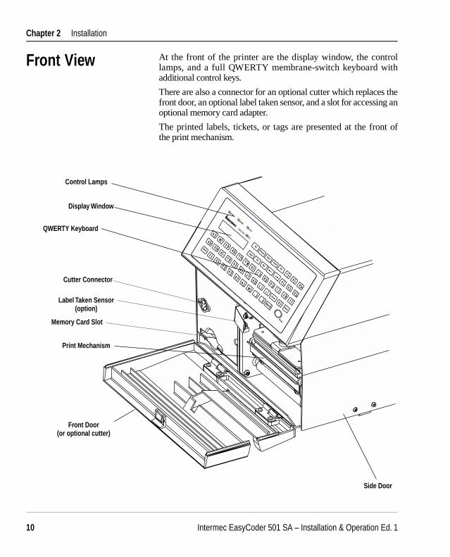
Front View At the front of the printer are the display window, the control lamps, and a full QWERTY membrane-switch keyboard with additional control keys.
There are also a connector for an optional cutter which replaces the front door, an optional label taken sensor, and a slot for accessing an optional memory card adapter.
The printed labels, tickets, or tags are presented at the front of the print mechanism.
Side Door
Control Lamps
Display Window
QWERTY Keyboard
Print Mechanism
Cutter Connector
Memory Card Slot
Front Door(or optional cutter)
Label Taken Sensor(option)

Intermec EasyCoder 501 SA – Installation & Operation Ed. 1 11
Chapter 2 Installation
Rear View The rear plate contains the On/Off switch, the AC power cord receptacle, the voltage switch, the standard serial interface, and various slots.
On/Off Switch
AC Power Cord Receptacle
Machine Label
RS-232 Serial Interface ("uart1:")
Provision for Optional Interface Board
Thermal P
rinter 5
01
Model #
1-501011-14
Serial #
115-230V 2.6-1.3A 50-60Hz
INTERMEC PRINTER AB
MADE IN SWEDEN
25016
This equipment c
omplies with
the re
quirements
for a Class
A computin
g device in
FCC Rules
Part 15 Subpart J
. Operatio
n of this d
evice in
a resid
ential a
rea may c
ause harm
ful interfe
rence
requiring th
e user to
take
whatever s
teps may b
e necessa
ry to co
rrect
the interfe
rence.
UL
LISTED 65B5R
N309
LR67809
VD
E
geprüfte
Sicherheit
Upper External Media Slot
Lower External Media Slot
Voltage Switch (115/230 VAC)
Display Contrast Adjustment

Intermec EasyCoder 501 SA – Installation & Operation Ed. 112
Chapter 2 Installation
∆∆
Media Compartment
The media compartment becomes accessible when the right-hand door and the front door or the cutter are opened. Although the printer is operable when the doors are left opened or completely removed, you are strongly recommended to keep them closed during normal operation, so as to prevent the print mechanism and the media from being exposed to dust.

Intermec EasyCoder 501 SA – Installation & Operation Ed. 1 13
Chapter 2 Installation
∆∆
Media Com-partment, cont.
The illustration below shows an EasyCoder 501 SA with some options installed. There are more options that are not illustrated here. Refer the Appendix 1 for complete lists of standard features and options for the EasyCoder 501 SA.
Ribbon Supply Hub
Thermal Printhead
Tear Bar
Printhead Lift Lever
Slack Absorber
Liner Takeupand Guide Shaft
(option)
Batch Takeup Guide (option)
3-inch Adapter
Media Supply Hub
Media RollRetainer(option)
External Supply Guides(option)
Ribbon Rewind Hub
Cutter(option)
Label Taken Sensor(option)

Intermec EasyCoder 501 SA – Installation & Operation Ed. 114
Chapter 2 Installation
The print unit features a high performance 8 or 11.81 dots/mm (203.2 or 300 dots/inch) thermal printhead with quick-mount fi ttings to facilitate replacement.
Print Unit
Printhead Lift Lever
Printhead Pressure Adjustment
Platen Roller
Tear Bar
Liner Drive Roller
Thermal Printhead
Printhead Lock

Intermec EasyCoder 501 SA – Installation & Operation Ed. 1 15
Chapter 2 Installation
Connections
Power
Computer
1 Place the printer on a level surface, near an AC outlet. You should be able to easily access the printer to load media and to remove the printout.
2 Check that the printer is switched off.3 Check that the printer is set for the correct voltage (115 or
230 VAC).4 Connect the power cord between the receptacle on the rear plate
and to the electrical outlet.
The EasyCoder 501 SA is always fi tted with one 25-pin D-style subminiature (DB25) female connector for the serial interface port "uart1:" (see Appendix 4).
• Serial Interface "uart1:" (device name: "uart1:") This interface is by default set for RS-232 communication, but
can also be confi gured for either RS-422 or 20 mA current loop. Before you can use the serial interface, you may need to change the default settings of the communication parameters, such as baud rate, parity, etc. as described in Chapter 6, “Setting Up the Printer.”
• Optional Interface Board (device name: "uart2:", "uart3:", or "centronics:") Several types are available (see Chapter 8, “Options”). Refer to
Appendix 4 and the separate documentation delivered with the boards for connection and setup instructions.
Switch off both the PC and the printer before connecting them together.

Intermec EasyCoder 501 SA – Installation & Operation Ed. 116
Chapter 2 Installation
Controls and IndicatorsControl Lamps
The EasyCoder 501 SA has several ways of communicating directly with its operator: three control lamps, a display window, a membrane-switch keyboard, and a beeper.
The control lamps are colored LEDs (Light Emitting Diodes) and are used for the following purposes:• Power (green) indicates when the power is on.• Ready (green) indicates when the printer is ready for use.• Error (red) indicates when some kind of error has occurred. If
using a serial communication, an error message may be returned to the host computer.
The display window contains an LCD (Liquid Crystal Display) and two lines of text, each with 16 characters. It guides the operator through the setup and indicates possible errors during printing.
The contrast of the display can be adjusted for the prevailing light conditions, as described in Chapter 11.
The EasyCoder 501 SA has a full QWERTY membrane-switch keyboard with additional control keys. Some keys have hard-coded functions, as described in the Intermec Stand-Alone Concept, Operating Instructions.
The beeper notifi es the operator when an error has occurred and acknowledges that a key has been pressed.
Display
Keyboard
Beeper
∆∆

Intermec EasyCoder 501 SA – Installation & Operation Ed. 1 17
Chapter 3
Starting UpStartup Files
Abbreviations:
EPROM: Erasable Programmable Read-Only MemoryOTPROM: One-Time Programmable Read-Only MemoryRAM: Random Access MemoryROM: Read-Only MemorySRAM: Static Random Access Memory
At startup, the behaviour of the printer is decided by the possible existence of a startup (autoexec) file (that is, a program that automatically starts running when the printer is switched on) somewhere in the printer’s memory. By default, the EasyCoder 501 SA is fi otted with the Intermec Stand-Alone program in its ROM memory.
There can be one startup fi le stored in each of the following parts of the printer’s memory: RAM, ROM, and memory cards (option). If there are startup fi les stored in more than one place, they will be used with the following priority:1. Dos-formatted memory cards (SRAM).2. Printer’s RAM memory.3. Non DOS-formatted memory cards (SRAM or OTPROM).4. Printer’s ROM memory, for example the configuration
EPROMs.
This implies that if you insert a memory card in the optional memory card adapter (see Chapter 8) with another startup fi le before you switch on the printer, the startup fi le of the memory card will be used instead of the Stand-Alone program.

Intermec EasyCoder 501 SA – Installation & Operation Ed. 118
Chapter 3 Starting Up
Switching On the Printer
Display Messages at Startup
Do not start the printer before you have made the necessary connections, inserted any memory card you may want to use, and checked that the printhead is lowered and an optional cutter is in closed position.
Switch on the power by means of the On/Off switch on the rear plate. The “Power” LED control lamp on the front panel lights up when the power is on. Wait for a few moments, while the printer loads the program and runs some self-diagnostic tests. If the printer is fi tted with a cutter, it will rotate to home position. Finally, a message will appear in the display window.
After starting up the printer for the fi rst time, keep the power on overnight to charge the memory backup battery.
While the printer loads the Stand-Alone program, the following message is shown in the display window:
STAND-ALONEPlease wait 1min
The fi rst time the Stand-Alone program is loaded, the printer will feed out two blank labels (or the quivalent) in order to adjust the media feed. Then a new message appears in the display window:
Select Mode1:Run 2:Set
Refer to the Intermec Stand-Alone Concept, Operating Instructions for further instruction on how to use the program.

Intermec EasyCoder 501 SA – Installation & Operation Ed. 1 19
Chapter 4
Open the front and side doors.Turn the printhead lift lever to “Load” posi-
tion.
Media LoadTear-Off(Straight-through)
The EasyCoder 501 SA can print on labels, tickets, tags, and continuous stock in various forms. This section describes the case when the media is to be torn off manually against the printer’s tear bar. This method is also known as “straight-through printing.”
Tear-off can be used for:• Non-adhesive continuous stock• Self-adhesive continuous stock with liner• Linerless self-adhesive continuous stock• Self-adhesive labels with liner• Tickets with gaps, with or without perforations• Tickets with black marks, with or without perforations
1 2
∆∆

Intermec EasyCoder 501 SA – Installation & Operation Ed. 120
Chapter 4 Media Load
Tear-Off, cont.
Remove any empty core from the mediasupply hub.
Fit a new roll of media on the supply hub and push the roll inwards as far as it will go.
43
In case of a media roll with a 76.2 mm (3 inches) core, fi rst fi t the adapter on the media
supply hub.
38-40 mm
(1.5 in)
5a 5b
Turn the label slack absorber clockwise so it snap-locks in open position.
76 mm
(3 in)

Intermec EasyCoder 501 SA – Installation & Operation Ed. 1 21
Chapter 4 Media Load
Tear-Off, cont.
Route the media under the guide plate of the label stop sensor and push it inwards towards
the center section as far as it will go.
This diagram shows the media path.
8 9
6 7
Turn the printhead lift lever to “Print” posi-tion.
Pull out the media and route it under the slack absorber and through the print unit as illus-trated. Then push the roll inward on the hub.
LoL
∆∆

Intermec EasyCoder 501 SA – Installation & Operation Ed. 122
Chapter 4 Media Load
∆∆
∆∆
# 1
# 2
2x ∆∆
# 1
# 2
Tear-Off, cont.
10 11
13
Close the front and side doors.
Tear of the media by pulling it downwards against the tear bar.
12
Feed out two blank copies by pressing the Print key twice.
2.1.Release the slack absorber (1). Adjust the
green edge guide so the media is guided with a minimum of play (2).

Intermec EasyCoder 501 SA – Installation & Operation Ed. 1 23
Chapter 4 Media Load
Cut-Off The EasyCoder 501 SA printers can print on labels, tickets, tags, and continuous stock in various forms. This section describes the case when the media is to be cut off by an optional automatic cutter.
Cut-off can be used for:• Non-adhesive continuous stock• Self-adhesive continuous stock with liner• Self-adhesive labels with liner (cut only liner between labels)
The cutter is designed to cut through paper-based media with a thickness of max 175 µm, whick roughly corresponds to a paper weight of 175 grams/m2 (basis weight 120 lb). The cutter should not be used to cut through labels, because the adhesive will stick to the shears, which can damage the cutter.
The cutter is held by a snap-lock and can be tilted forward to facilitate media load.
Switch off the power using the On/Off switch on the printer’s rear plate.
1
Open the cutter and the right-hand door.
2
Warning!The cutting edge will rotate when the power is switched on and when the printer is rebooted. Always switch off the power before opening the cutter unit.
∆∆

Intermec EasyCoder 501 SA – Installation & Operation Ed. 124
Chapter 4 Media Load
Cut-Off, cont.
3
Turn the printhead lift lever to “Load” posi-tion.
4
5 6a
Remove any empty core from the mediasupply hub.
Fit a new roll of media on the supply hub and push the roll inwards as far as it will go.
38-40 mm
(1.5 in)
Turn the label slack absorber clockwise so it snap-locks in open position.

Intermec EasyCoder 501 SA – Installation & Operation Ed. 1 25
Chapter 4 Media Load
Cut-Off, cont.
6b 7
9
Route the media under the guide plate of the label stop sensor and push it inwards towards
the center section as far as it will go.
8
This diagram shows the media path.
In case of a media roll with a 76.2 mm (3 inches) core, fi rst fi t the adapter on the media
supply hub.
76 mm
(3 in)
Pull out the media and route it under the slack absorber and through the print unit as illus-trated. Then push the roll inward on the hub.
LoL
∆∆

Intermec EasyCoder 501 SA – Installation & Operation Ed. 126
Chapter 4 Media Load
Cut-Off, cont.
Route the media through the cutter between the two guide plates.
11
12 13
Close the cutter while pulling at the end of the media. Close the right-hand door.
∆∆
10
∆∆
2.1.Release the slack absorber (1). Adjust the
green edge guide so the media is guided with a minimum of play (2).
Turn the printhead lift lever to “Print” posi-tion.

Intermec EasyCoder 501 SA – Installation & Operation Ed. 1 27
Chapter 4 Media Load
Cut-Off, cont.
Feed out and cut two blank copies by pressing the Print key twice.
15
∆∆
# 2
# 1
2x
14
Switch on the power.
Intermec EasyCoder 501 SA – Installation & Operation Ed. 128
Chapter 4 Media Load
Peel-Off(Self-strip)
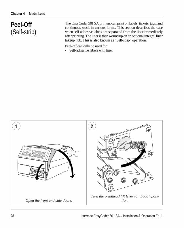
The EasyCoder 501 SA printers can print on labels, tickets, tags, and continuous stock in various forms. This section describes the case when self-adhesive labels are separated from the liner immediately after printing. The liner is then wound up on an optional integral liner takeup hub. This is also known as “Self-strip” operation.
Peel-off can only be used for:• Self-adhesive labels with liner
1 2
Open the front and side doors.Turn the printhead lift lever to “Load” posi-
tion.
∆∆

Intermec EasyCoder 501 SA – Installation & Operation Ed. 1 29
Chapter 4 Media Load
Peel-Off, cont.
3
Pull out the green clip (1) on the liner takeup hub and dispose of all wound-up liner (2).
4
6a
Fit a new roll of labels on the supply hub and push the roll inwards as far as it will go.
38-40 mm
(1.5 in)
1.
2.
5
Remove any empty core from the mediasupply hub.
Turn the label slack absorber clockwise so it snap-locks in open position.

Intermec EasyCoder 501 SA – Installation & Operation Ed. 130
Chapter 4 Media Load
Peel-Off, cont.
Route the media under the guide plate of the label stop sensor and push it inwards towards
the center section as far as it will go.This diagram shows the path of the labels and
the liner.
8 9
6b
In case of a label roll with a 76.2 mm (3 inches) core, fi rst fi t the adapter on the media
supply hub.
76 mm
(3 in)
7
Pull out the media and route it under the slack absorber and through the print unit as illus-trated. Then push the roll inward on the hub.
LoL
∆∆

Intermec EasyCoder 501 SA – Installation & Operation Ed. 1 31
Chapter 4 Media Load
Peel-Off, cont.
Route the liner around the platen roller and the tear bar, then rearwards under the print
unit.
Secure the liner to the takeup hub with the clip (1) and wind up some of the liner so it becomes
tight (2).
10 11
∆∆
1.2.
12
Turn the printhead lift lever to “Print” posi-tion.
13
Pull out approximately 40 cm (15 inches) of labels and peel off the labels manually from
the liner.
40 cm/15 in
∆∆
Intermec EasyCoder 501 SA – Installation & Operation Ed. 132
Chapter 4 Media Load
Peel-Off, cont.
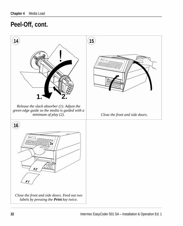
1514
16
Close the front and side doors. Feed out two labels by pressing the Print key twice.
∆∆
# 1
# 2
2x
# 2
# 1
∆∆
Close the front and side doors.
2.1.Release the slack absorber (1). Adjust the
green edge guide so the media is guided with a minimum of play (2).

Intermec EasyCoder 501 SA – Installation & Operation Ed. 1 33
Chapter 4 Media Load
Internal Batch Takeup
The EasyCoder 501 SA printers can print on labels, tickets, tags, and continuous stock in various forms. This chapter describes the case when printed labels fitted on liner (backing paper) or pre-perforated tickets and tags are wound up inside the printer. The roll of printed labels, tickets, or tags can then be removed and be handled manually. This requires an optional internal liner takeup unit and a batch takeup guide.
The takeup hub can accommodate 1/4 to 1/3 of a full-size media roll.
Internal batch takeup can be used for:• Self-adhesive labels fi tted on liner• Preperforated tickets with gaps• Preperforated tickets with marks
1 2
Open the front and side doors.Turn the printhead lift lever to “Load” posi-
tion.
∆∆
Intermec EasyCoder 501 SA – Installation & Operation Ed. 134
Chapter 4 Media Load
Internal Batch Takeup, cont.
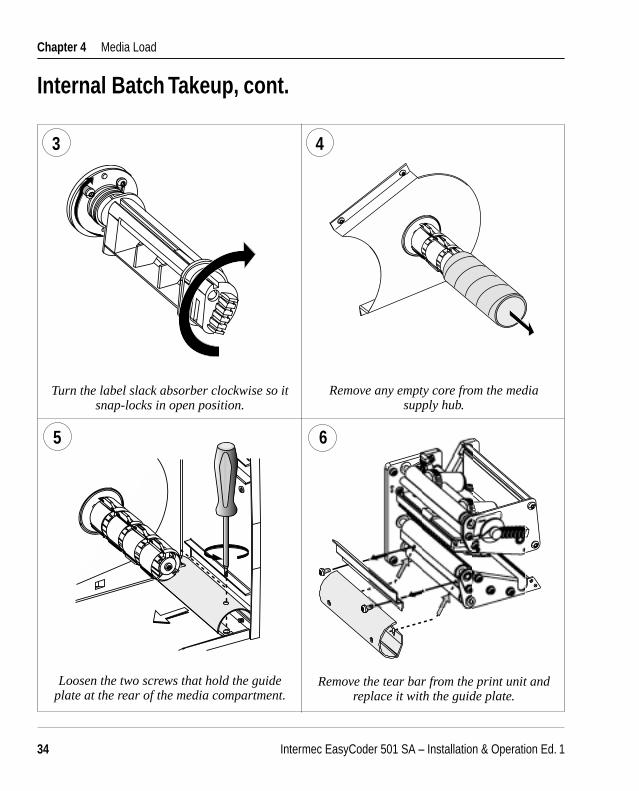
3 4
5
Remove any empty core from the mediasupply hub.
Remove the tear bar from the print unit and replace it with the guide plate.
Loosen the two screws that hold the guide plate at the rear of the media compartment.
6
Turn the label slack absorber clockwise so it snap-locks in open position.

Intermec EasyCoder 501 SA – Installation & Operation Ed. 1 35
Chapter 4 Media Load
Fit a new roll of media on the supply hub and push the roll inwards as far as it will go.
38-40 mm
(1.5 in)
Internal Batch Takeup, cont.
In case of a media roll with a 76.2 mm (3 inches) core, fi rst fi t the adapter on the media
supply hub.
76 mm
(3 in)
7b
Route the media under the guide plate of the label stop sensor and push it inwards towards
the center section as far as it will go.
8 9
7a
Pull out the media and route it under the slack absorber and through the print unit as illus-trated. Then push the roll inward on the hub.
LoL
∆∆

Intermec EasyCoder 501 SA – Installation & Operation Ed. 136
Chapter 4 Media Load
Internal Batch Takeup, cont.
Pull out approximately 40 cm (15 inches) of media.
Route the media around the guide plate and back under the print unit to the takeup hub.
10 11
40 cm/15 in
∆∆
∆∆
Wind up some of the media on the takeup hub and secure it with the clip.
12 13
1.2.
This diagram shows the path of the media.

Intermec EasyCoder 501 SA – Installation & Operation Ed. 1 37
Chapter 4 Media Load
Turn the printhead lift lever to “Print” posi-tion.
Internal Batch Takeup, cont.
14 15
17
Close the right-hand door but keep the front door open.
Feed two blank copies by pressing the Print key.
∆∆
∆∆
2x
16
2.1.Release the slack absorber (1). Adjust the
green edge guide so the media is guided with a minimum of play (2).

Intermec EasyCoder 501 SA – Installation & Operation Ed. 138
Chapter 4 Media Load
1 2
External Supply
Use the upper slot in the rear plate when the supply is at the same level as the printer and
when using peel-off operation.
The EasyCoder 501 SA can print on labels, tickets, tags, and continuous stock in various forms. This chapter describes the case when an external media supply is used, for example a stack of fan-fold tickets or an external media roll.
It is possible to simply let the media enter the printer through either of the two slots in the rear plate. However, we recommend to fi t the optional Intermec Fan-Fold Kit, which provides better guidance of the media using adjustable guides. The kit can be fi tted to either the upper or the lower slot in the rear plate.
When using an external media supply, take care to protect the media from dust, dirt, and other foreign particles, that can impair the printout quality or cause unneccessary wear to the printhead.
Depending on brand and quality, all direct thermal media are more or less sensitive to heat, direct sunlight, moisture, oil, plasticizers, fat, amd other substances. You should protect it accordingly.
External supply can be used for:• Tear-off operation• Cut-off operation• Peel-off operation (upper slot only)• Internal batch takeup operation
Use the lower slot in the rear plate when the supply is placed lower than the printer.
Intermec EasyCoder 501 SA – Installation & Operation Ed. 1 39
Chapter 4 Media Load
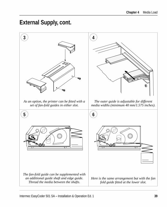
3 4
5 6
External Supply, cont.
As an option, the printer can be fi tted with a set of fan-fold guides in either slot.
The outer guide is adjustable for different media widths (minimum 40 mm/1.575 inches).
The fan-fold guide can be supplemented with an additional guide shaft and edge guide.
Thread the media between the shafts.Here is the same arrangement but with the fan
fold guide fi tted at the lower slot.

Intermec EasyCoder 501 SA – Installation & Operation Ed. 140
Chapter 5
Ribbon Load
Open the front and right-hand doors.
1
Turn the printhead lift lever to “Open” posi-tion.
Thermal Transfer PrintingThe EasyCoder 501 SA can print on labels, tickets, tags, and contionuous stock using either direct thermal printing on special heat-sensitive media or thermal transfer printing using a special ink-coated ribbon. For thermal transfer printing, the printer must be fi tted with a transfer ribbon mechanism.
Thermal transfer printing makes it possible to use a wide range of receiving face materials. Make sure to select a type of ribbon that matches the type of receiving face material (see Appendix 2, “Media Specifi cation”) and to set up the printer properly (see Chapter 6, “Setting Up the Printer”).
The EasyCoder 501 SA can only use transfer ribbon rolls wound with the ink-coated side facing inwards.
Most transfer ribbons do not smear at room temperature.
2
∆∆

Intermec EasyCoder 501 SA – Installation & Operation Ed. 1 41
Chapter 5 Thermal Transfer Printing
Ribbon Load, cont.
Unpack a roll of original Intermec thermal transfer ribbon.
In case of ribbon up to 60 mm (2.2 in.) wide, compress the ribbon supply bobbin and move it
so it snaps into the fi rst (innermost) grove.
In case of 88 to 90 mm (3.5 in.) ribbon width, compress the ribbon supply bobbin and move it
so it snaps into the second grove.
3 4
5a
In case of ribbon reload, remove any used ribbon and empty ribbon core.
TEAR-OFF
5b
<60 mm(2.3 in)
#1
88–90 mm(3.5 in)
#2

Intermec EasyCoder 501 SA – Installation & Operation Ed. 142
Chapter 5 Thermal Transfer Printing
Ribbon Load, cont.
In case of 110 mm (4.3 in.) ribbon width, com-press the ribbon supply bobbin and move it so
it snaps into the third grove.
Press the ribbon roll onto the ribbon supply bobbin (1) and route the ribbon through the print unit. Pull out approx. 20 cm (8 in.) of
ribbon (2).
Without releasing the ribbon, turn the print-head lift lever to “Print” position so as to lock
the ribbon.
6
7 8
Be careful to route the ribbon above the handle of the label stop sensor. The ribbon must be
fi tted so both spools will rotate counterclock-wise as illustrated above.
5c
110 mm(4.3 in)
#3
2.
1.
!

Intermec EasyCoder 501 SA – Installation & Operation Ed. 1 43
Chapter 5 Thermal Transfer Printing
Ribbon Load, cont.
Press the cardboard core at the front end of the ribbon onto the rewind hub.
Turn the printhead lift lever to “Load” posi-tion.
Close the front and side doors.
10
11 12
Wind up the ribbon until all of the transparent leader has passed the printhead and the ribbon
becomes tight. Then turn the printhead lift lever to “Print position”.
9
TEAR-OFF
∆∆
TEAR-OFF

Intermec EasyCoder 501 XP – Installation & Operation Ed. 144
Chapter 6
Setting Up the PrinterDescription The setup controls the printer in regard of serial communication,
media feed, and print speed, and specifi es which type of media and (optionally) ribbon is loaded in the printer.
Check the list of the printer's default setup parameters below to see if they match your requirements. If not, you will have to change the setup as described in Chapter 7, “Setup Mode.” Also refer to the Intermec Stand-Alone Concept, Operating Instructions for information on how to change setup parameters outside the Setup Mode.
The printer’s default setup with Intermec Stand-Alone program is listed below:Default Setup
Contrast Middle (5)
Ser-Com ("uart1:") Baud rate: 9600 Parity: none Character length: 7 bits Stop bits: 2 bits RTS/CTS: Disable ENQ/ACK: Disable XON/XOFF, data to host: Enable XON/XOFF, data from host: Enable New line: CR/LF
Detection Feedadjust: Startadjust: 0 Stopadjust: 0
Service Media Size: X-start (8 /11.81 dots per mm): 0/0 Width (8 /11.81 dots per mm): 832/1280 Length (8 /11.81 dots per mm): 1200/1200 Media type: Label (w Gaps) Print defs: Paper type (thermal transfer printers): UBI HP 20 Paper type (direct thermal printers): RICOH 130LAB/LAM Performance: Normal Memory alloc: Image buffer size: 64 Kbytes
Receive buffer: 6000 bytes Transmit buffer: 300 bytes
Intermec EasyCoder 501 XP – Installation & Operation Ed. 1 45
Chapter 6 Setting Up the Printer
Setup Parameters
Serial Communication• Baud Rate• Parity• Character Length• Stop Bits• Flow Control• New Line
The contrast setup allows you to make minor adjustments of the printout in regard of blackness, for example to compensate for variations in quality between different batches of the same media or ribbon.
The serial communication parameters control the communication between the printer and the connected computer or other devices on the standard serial port "uart1:" and the optional serial ports "uart2:" and "uart3:". The optional ports require installation of an optional interface board. The printer’s fi rmware detects the presence of an interface baord and presenst additional sets of communication setup menus depending on type of communication (see overviews in Chapter 7).
The serial communication parameters have no effect on parallel communications or on the IN and OUT ports on the optional Industrial Interface Board.
For the serial communication channel "uart1", the following parameters can be set. Make sure they match the setup of the connected device or vice versa. If the setup of the printer and the setup of the host do not match, the response from the printer to host will be garbled.
Baud RateThe baud rate is the transmission speed in bits per second. There are seven options:
• 300• 600• 1200• 2400• 4800• 9600 (default)• 19200
In case of communicatuions problems, try a lower baud rate. 9600 is the highest recommended baud rate for 20 mA current loop communication.
Contrast
Intermec EasyCoder 501 XP – Installation & Operation Ed. 146
Chapter 6 Setting Up the Printer
Setup Parameters, cont.
Serial Communication, cont.
ParityThe parity decides how the fi rmware will check for transmission errors. There are fi ve options:
• None (default)• Even• Odd• Mark• Space
Character LengthThe character length specifi es the number of bits that will defi ne a character. Eight bits allows more special characters and characters specific for foreign laguages to be used. Refer to the Intermec Fingerprint v6.14, Reference Manual for information on which characters are available in various combinations of character length and character set.
• 7 Characters ASCII 000 to 127 decimal (default) • 8 Characters ASCII 000 to 255 decimal
Stop BitsThe number of stop bits specifi es how many bits will defi ne the end of a character. There are two options:
• 1 • 2 (default)
Flow ControlThere are several ways to control the exchange of data (“handshak-ing”) between the printer and the connected computer or other device. Each option can be enabled or disabled separately, but normally only one alternative should be enabled. For galvanically insulated interfaces (that is, 20 mA current loop and RS-422), ENQ/ACK or XON/XOFF are to prefer in order to retain interference protection and to limit the number of lines.

Intermec EasyCoder 501 XP – Installation & Operation Ed. 1 47
Chapter 6 Setting Up the Printer
• RTS/CTS RTS/CTS is a protocol where the communication is controlled by
currents through separate lines in the cable being set either to high or low. By default, this option is disabled.
RTS high indicates that the transmitting unit is able to receive characters. RTS low indicates that the receive buffer is fi lled to 75% (see XON/XOFF).
CTS high indicates that the unit transmitting the CTS signal is ready to receive data. CTS low indicates that the receive buffer is full (see XON/XOFF). In some computer programs, for example MS Windows Terminal, RTS/CTS is designated “Hardware.”
• DTR DTR (“Data Terminal Ready”) is not controlled in the setup mode,
but by straps on the CPU board or interface board. DTR high indicates that the transmitting unit is switched on.
• ENQ/ACK In this protocol, the communication is controlled by the control
characters ENQ (ASCII 05 dec.) and ACK (ASCII 06 dec.) being transmitted on the same line as the data. The sending unit transmits ENQ at regular intervals. If the response ACK is not received, the transmission is held up awaiting an ACK character from the receiving unit. By default, ENQ/ACK is disabled.
• XON/XOFF In this protocol, the communication is controlled by the control
characters XON (ASCII 17 dec.) and XOFF (ASCII 19 dec.) being transmitted on the same line as the data. XON/XOFF can be enabled/disabled separately for data received from the host by the printer (printer sends XON/XOFF) and for data transmitted to the host from the printer (host sends XON/XOFF).
XOFF is sent from the printer when its receive buffer is fi lled to 75%, and the transmission from the host is held, waiting for an XON character. When enough data have been processed so the receive buffer is fi lled only to 50%, the printer sends an XON character and the host resumes transmitting data. The same principles apply to XON/XOFF sent by the host, even if the percentage fi gure may differ.
By default, XON/XOFF is disabled for data both ways.
Setup Parameters, cont.
Serial Communication, cont.

Intermec EasyCoder 501 XP – Installation & Operation Ed. 148
Chapter 6 Setting Up the Printer
New LineSelects the character(s) transmitted from the printer to specify the switching to a new line. There are three options:
• CR/LF ASCII 13 dec. + ASCII 10 dec. (default)• LF ASCII 10 dec.• CR ASCII 13 dec.
LSS AdjustmentThe LSS is a photo-electric detection device that controls the media feed. Situated inside the printing mechanism, it detects the front edges of the labels, slits in tickets or tags, or the rear edges of black marks on the back side of the media.
If the printer is set up for “Label (w gaps)”, “Ticket (w gaps)”, “Fix length strip”, or “Var. length strip”, a narrow beam of light is emitted from the upper part of the LSS and received by the sensor in the lower part.
Non-transparent media will block the beam completely, whereas semi-transparent liner between labels will allow some of the light to pass through.
Detection gaps in the continuous stock cause no interference at all.
An out-of-paper condition is assumed, when no interference to the beam has been detected within a feed length corresponding to the distance between the dot line on the printhead and the sensor.
Setup Parameters, cont.
Detection• LSS Adjustment• Feed Adjustment
Serial Communication, cont.
Light Emitter
Light Emitter and Receiver
Media Path

Intermec EasyCoder 501 XP – Installation & Operation Ed. 1 49
Chapter 6 Setting Up the Printer
LSS Adjustment, cont.
When the printer is set up for “Ticket (w mark)”, the light is emitted from the lower part of the LSS. The beam can be refl ected back to the receiver by the white back side of the media. If the beam hits a black mark, practically no light will be refl ected back. An out-of-paper condition is assumed, when no refl ected light has been detected within a feed length corresponding to the distance between the dot line on the printhead and the sensor.
Obviously, it is important that the printer is set up for the correct type of media (see “Media Type” later in this chapter) so the fi rmware can interpret the signals correctly.
The LSS can be moved max. 50 mm sideways across the web as described in Chapter 11.
The LSS is automatically fi ne-adjusted when a Testfeed operation is performed. Moreover, the LSS receiver can be adjusted by means of a potentiometer on the CPU board (see Appendix 3).
If the printer works as expected, there is no need to adjust the LSS, but if the printer starts to feed out labels or tickets in an unexpected manner, check that the sensor is properly aligned in relation to the web and that it has not become dirty. Perform a few Testfeed operations to allow the sensor to auto-adjust itself.
If the error remains, proceed according to the description of the Setup Mode for the printer model in question. Only as a last resort should the potentiometer be adjusted.
Feed AdjustmentThe Feed Adjustment controls how much of the media is fed out or pulled back before and/or after the actual printing. These settings are global and will be effected regardless of which program is run.
Note that the fi rmware detects the front edges of labels w. gaps, the ends of detection slots, and the forward edges of black marks for detection, all seen in relation to the feed direction.
Setup Parameters, cont.
Detection, cont.

Intermec EasyCoder 501 XP – Installation & Operation Ed. 150
Chapter 6 Setting Up the Printer
Feed Adjustment, cont.Start AdjustThe Start Adjust value is given as a positive or negative number of dots. Default value is 0, which places the origin a certain distance back from the forward edge of the copy.• A positive start adjustment means that the specifi ed length of
media will be fed out before the printing starts. Thus, the origin is moved further back from the forward edge of the copy.
• A negative start adjustment means that the specifi ed length of media will be pulled back before the printing starts. Thus, the origin is moved towards the forward edge of the copy.
Stop AdjustThe Stop Adjust value is given as a positive or negative number of dots. Default value is 0, which stops the media feed in a position suitable for tear off operation.• A positive stop adjustment means that the normal media
feed after the printing is completed will be increased by the specifi ed value.
• A negative stop adjustment means that the normal media feed after the printing is completed will be decreased by the specifi ed value.
Recommended Feed Adjustments (print from top of form): Labels (peel-off) 8 dots/mm 11.81 dots/mmStart adjust: -90 -135Stop adjust: -24 -36Tickets and Tags (tear-off)Start adjust: -114 -171Stop adjust: 0 0Continuos stock (tear-off)Start adjust: -114 -171Stop adjust: 70 105Cutting between labels:Start adjust: -294 -441Stop adjust: +180 +270Continuos stock (cut-off)Start adjust: -294 -441Stop adjust: +250 +375
Setup Parameters, cont.
Detection, cont.
Printhead Density
8 dots/mm (203.2 dpi) Both directions: 1 dot = 0.125 mm = 4.92 mils
11.81 dots/mm (300 dpi) Across the web (11.81 dots/mm):1 dot = 0.085 mm = 3.33 milsAlong the web (12 dots/mm):1 dot = 0.083 mm = 3.28 mils
Note:The feed adjustment values listed in this chapter are approximate values to be used initially. Due to personal preferences, differ-ences between applications, and minor mechanical differences between individual printers, the values may need to be fi ne-adjusted after testing.

Intermec EasyCoder 501 XP – Installation & Operation Ed. 1 51
Chapter 6 Setting Up the Printer
Media SizeTo protect the printhead from the potentially harmful condition of printing outside the media and to allow detection of out-of-paper errors, a printable area must be specifi ed by the use of the setup parameters X-start, Width, and Length.
• X-start specifi es the position of the origin along the dots on the printhead. By default, X-start is set to 0 which corresponds to the dot closest to the printer’s center section.
Printhead density 8 dots/mm 11.81 dots/mm Number of dots on printhead: 832 1280
Max. print width: 104 mm (4.1 in) 108.3 mm (4.3 in)
By setting a value larger than 0, you will move the origin outwards, away from the inner edge of the media. In other words, the larger X-start value, the wider inner margin, and the less printable area.
• Width specifi es the width of the printable area as a number of dots from the origin. The sum of the X-start value and the width value gives the outer margin of the printable area. The width must not be so large so as to allow printing outside the media.
• Length serves three purposes: - To decide the length of the printable area as a number of dots. - To decide the amount of media feed when using “fi x length
strip”. - To set an “emergency stop”, which works when the printer
is set up for “Label (w gaps)”, “Ticket (w mark)”, or “Ticket (w gaps)”. If the LSS has not detected a gap or mark within 150% of the set length, the media feed is automatically stopped to avoid feeding out a whole roll of media, because of a faulty sensor.
This implies that you can use labels or tickets longer than the printable area as illustrated by the following table:
Printhead density: 8 dots/mm 11.81 dots/mm Max. print length (9999): 1,250 mm (49.2 in) 833 mm (32.8 in) Max. copy length: 1,875 mm (73.8 in) 1,250 mm (49.2 in)
By setting up media size, you will create a “print window” in which the printing can be performed. Any fi eld protruding outside the print window in any direction will cause an error condition (Error 1003 “Field out of label”) and the printing will be inhibited.
Setup Parameters, cont.
Service• Media Size• Media Type• Print Defs• Performance• Memory Alloc

Intermec EasyCoder 501 XP – Installation & Operation Ed. 152
Chapter 6 Setting Up the Printer
Setup Parameters, cont.
Service, cont. Print Window8 dots/mm (203.2 dpi) printhead in left-hand positionThe 8 dots/mm printhead can be fi tted in two positions. When the printhead is fitted in the innermost, left-hand position (see illustration), dot No. 0 is aligned with the inner edge of the media. Since the maximum print width is 104 mm (4.1 in) and the maximum media width is 120 mm (4.7 in), this leaves a margin of at least 16 mm (0.6 in) along the outer edge of the media, where no printing can be performed.
FEEDDIRECTIONDot 0
Dot-lineon printhead
X-start Width
Origin
Length
Frommedia supply
Dot 831
16 mm (0.63 in)
PRINTWINDOW
max. 120 mm (4.7 in)
104 mm (4.1 in)

Intermec EasyCoder 501 XP – Installation & Operation Ed. 1 53
Chapter 6 Setting Up the Printer
Setup Parameters, cont.
Service, cont. Print Window8 dots/mm (203.2 dpi) printhead in right-hand positionThe 8 dots/mm printhead can be fi tted in two positions. When the printhead is fi tted in the outer, right-hand position (see illustration), dot No. 0 is situated 3 mm (0.12 in) inwards from the inner edge of the media. Since the maximum print width is 104 mm (4.1 in) and the maximum media width is 120 mm (4.7 in), this leaves a margin of at least 13 mm (0.51 in) along the outer edge of the media, where no printing can be performed. Furthermore, if 110 mm (4.33 in) wide media is used, the printhead will be centered with a 3 mm (0.12 in) wide margin on either side.
Dot 0
X-start Width
Origin
Length
Dot 831FEED
DIRECTION
Dot-lineon printhead
Frommedia supply
13 mm (0.51 in)
110 mm (4.33 in)
3 mm (0.12 in)
max. 120 mm (4.7 in)
104 mm (4.1")
PRINTWINDOW

Intermec EasyCoder 501 XP – Installation & Operation Ed. 154
Chapter 6 Setting Up the Printer
Setup Parameters, cont.
Service, cont. Print Window 11.81 dots/mm (300 dpi) printhead in right-hand positionThe 11.81 dots/mm printhead should only be fi tted in the right-hand position (see illustration). Dot No. 0 is situated 0.8 mm (0.03 in) inwards of the inner edge of the media. Since the maximum print width is 108.3 mm (4.26 in) and the maximum media width is 120 mm (4.7 in), this leaves a margin of at least 10.9 mm (0.43 in) along the outer edge of the media, where no printing can be performed.
Dot 0
X-start Width
Origin
Length
Dot 1279
FEEDDIRECTION
Dot-lineon printhead
Frommedia supply
10.9 mm (0.43 in)
max. 120 mm (4.7 in)
108.3 mm (4.26 in)
0.8 mm (0.03 in)
PRINTWINDOW

Intermec EasyCoder 501 XP – Installation & Operation Ed. 1 55
Chapter 6 Setting Up the Printer
Media TypeThe Media Type parameters control how the label stop sensor (LSS) and the media feed work. There are fi ve media type options:• Label (w gaps) is used for adhesive labels mounted on liner.• Ticket (w mark) is used for labels, tickets, or continuous stock
provided with black marks at the back.• Ticket (w gaps) is used for tickets and tags with detection slits. • Fix length strip is used for continuous stock where the length of the
print window decides the length of media to be fed out.• Var length strip is used for continuous stock and adds 115 dots
of media feed after the last printable dot (may even be a blank space character or a “white dot” in an image or character cell) to allow the media to be properly torn off.
It is important to select the correct media type, so the printer can indicate possible errors. Two error conditions may occur:• Error 1005 “Out of paper” indicates that the last ordered copy
could not be printed because of an empty media stock.• Error 1031 “Next label not found” indicates that the last ordered
label or ticket was successfully printed, but no more labels/tickets can be printed because of an empty media stock.
Setup Parameters, cont.
Service, cont.

Intermec EasyCoder 501 XP – Installation & Operation Ed. 156
Chapter 6 Setting Up the Printer
Setup Parameters, cont.
Service, cont. Print DefsThe Print Defi nes section contains four types of setup parameters:• Head Resistance• Paper Type• New Supplies• Test Print
Head ResistanceThe power to the printhead is adjusted automatically according to the printhead resistance each time the printer is started. There is no manual head resistance setup.
Paper TypeTo obtain the best printout quality, the printer should be set up for the characteristics of the brand of direct thermal media or transfer ribbon currently used, see “Selecting Paper Type Settings” later in this chapter. Any attempt to print with transfer ribbon loaded and the printer set up for direct thermal media, or vice versa, will result in an error condition (Error 1027 “Out of transfer ribbon” or Error 1058 “Transfer ribbon fi tted”).
Note:In EasyCoder 501 printers without any thermal transfer mechanism, only direct thermal media options are available. New SuppliesOther types of supplies, than those included as standard options for the Paper Type setup parameter, can be selected by means of a 13 digit code, provided by the manufacturer or distributor. Once a new supply has been selected using “New Supplies”, it will be stored in the RAM memory and appear as an additional option for the “Paper Type” parameter, where it is specifi ed by the fi rst 4 digits in its 13 digit code number. The fi rst digit indicates direct thermal media (0) or thermal transfer ribbon (1).

Intermec EasyCoder 501 XP – Installation & Operation Ed. 1 57
Chapter 6 Setting Up the Printer
Selecting Paper Type SettingsThe printer can be set for various types of supplies using of the setup parameter “Paper Type”. The “Paper Type” settings provide different levels of energy to the printhead dots to match the characteristics of the supplies in use to give the best combination of printout quality and printhead life. The use of supplies that require less energy will prolong the life of the printhead. The “Contrast” setup parameter can be used to fi ne-adjust the printout darkness within each “Paper Type” option.
• Direct Thermal Printing The recommended standard “Paper Type” options for direct
thermal printing are shown in the table below. If you are not sure how to set the “Paper Type” parameter, fi rst try the lowest energy setting (UBI DT 120), then the highest (UBI DT 110), and use the one that gives the best printout quality.
Option Media Quality Energy
UBI DT 120 Synthermal LowUBI DT 110 Premium, Economy High
The options UBI DT 120 and UBI DT 110 are optimized for bar code printing. This may cause an impression of a somewhat weak printout for pure text and image printing. Increasing the energy to the printhead will make the printout blacker at the expense of the quality of bar codes. When extra black printout is desired for ordinary direct thermal printing, use one of the following setup options:
UBI DT 110+ 15% more energy to printhead compared to UBI DT 110.
UBI DT 110++ 30% more energy to printhead compared to UBI DT 110. 8 dots/mm printers only.
Due to the increased amount of energy to the printhead, they should be used with extreme care as they put high stress on the printhead. Furthermore, a more frequent cleaning of the printhead is recommended with these setup options.
The additional “Paper Type” options that can be found in the setup (“KANZAKI 86S” and “RICOH 130 LAB/LAM”) are included for compatibility reasons only and must not be understood as approval of media with the said designations.
The generic term for transfer ribbons, receiving face materi-als, direct thermal media, and linerless media is “supplies.”
Service, cont.
Setup Parameters, cont.

Intermec EasyCoder 501 XP – Installation & Operation Ed. 158
Chapter 6 Setting Up the Printer
Setup Parameters, cont.
Service, cont. • Thermal Transfer Printing The recommended standard “Paper Type” options for thermal
transfer printing are shown in the table below in order from the lowest printing energy at the top to the highest at the bottom of the table. If you are not sure how to set the “Paper Type” parameter, start with the lowest energy setting (UBI GP 11) and work your way up towards the highest (UBI HR 30), until you achieve the best printout quality. Use of higher “Paper Type” levels than listed for each ribbon type should be avoided, but lower levels are preferred whenever an acceptable printout quality is obtained.
Option Ribbon Type Face Material Energy
UBI GP 11 General Purpose/ Matte Coated LowUBI GP 10 Standard Vellum/Uncoated ↓ UBI HP 21 High Performance/ High Gloss White ↓ UBI HP 201 Premium Matte Coated ↓ UBI HR 31 High Resistance/ Polyester Gloss ↓ UBI HR 30 Super Premium Polyester Matte High1/. Also try UBI HP 21.

Intermec EasyCoder 501 XP – Installation & Operation Ed. 1 59
Chapter 6 Setting Up the Printer
Setup Parameters, cont.
TestprintThis option allows you to print a series of test labels as illustrated below.
First, four test labels intended to facilitate adjustment of the printhead pressure and alignment are printed. Then comes one or more labels showing the printer's current setup, before the loop starts all over again.
Service, cont.
618 ohms / 8 dots
CODE39 CODE39
1 23 45 67 890128
CO
DE
39
CO
DE
39
UA
RT
1B
AU
DR
AT
E96
00P
AR
ITY
NO
NE
CH
AR
LE
NG
TH
7S
TO
PB
ITS
2R
TS
/CT
SD
ISA
BLE
EN
Q/A
CK
DIS
AB
LEX
ON
/XO
FF
DA
TA
FR
OM
HO
ST
EN
AB
LE D
AT
A T
O H
OS
TE
NA
BLE
NE
W L
INE
CR
/LF
PR
INT
CO
NF
IGC
ON
TR
AS
T5
LSS
AD
J80
ST
AR
TA
DJ
0S
TO
PA
DJ
0X
ST
AR
T0
WID
TH
832
LEN
GT
H12
00M
ED
IA T
YP
ELA
BE
L (w
GA
PS
)H
EA
D R
ES
IST
518
PA
PE
R T
YP
EU
BI H
P 2
0P
ER
FO
RM
AN
CE
NO
RM
AL
ME
MO
RY
AL
LO
CIM
AG
E B
UF
F S
IZE
48 K
BY
TE
RE
C B
UF
F U
AR
T1
300
BY
TE
TR
AN
S B
UF
F U
AR
T1
300
BY
TE
Test Label 1 Test Label 2
Test Label 3 Test Label 4
Test Label 5...

Intermec EasyCoder 501 XP – Installation & Operation Ed. 160
Chapter 6 Setting Up the Printer
Setup Parameters, cont.
Service, cont. PerformanceThe Performance setup parameter allows you to decide the print speed. Three options are displayed: Normal (default), High, and Ultra High. These options translate to different nominal print speeds depending on printhead density, type of printing, and type of supplies as illustrated by the tables below. Supplies, which have been specifi ed using the “New Supplies” option, have fi xed print speed settings that overrides the “Performance” setup.
Printhead density 8 dots/mm (203.2 dpi)Thermal Transfer Printing GP/Standard & HP/Premium RibbonsPerformance Text Printing Hor. Bar Code Vert. Bar CodeNormal 100 mm/sec (4 in/sec) 100 mm/sec (4 in/sec) 100 mm/sec (4 in/sec)High 200 mm/sec (8 in/sec) 200 mm/sec (8 in/sec) 100 mm/sec (4 in/sec)Ultra High 200 mm/sec (8 in/sec) 200 mm/sec (8 in/sec) 200 mm/sec (8 in/sec)
Thermal Transfer Printing HR/Super Premium Ribbons Performance Text Printing Hor. Bar Code Vert. Bar CodeNormal 100 mm/sec (4 in/sec) 100 mm/sec (4 in/sec) 100 mm/sec (4 in/sec)High 100 mm/sec (4 in/sec) 100 mm/sec (4 in/sec) 100 mm/sec (4 in/sec)Ultra High 100 mm/sec (4 in/sec) 100 mm/sec (4 in/sec) 100 mm/sec (4 in/sec)
Direct Thermal Printing Performance Text Printing Hor. Bar Code Vert. Bar CodeNormal 100 mm/sec (4 in/sec) 100 mm/sec (4 in/sec) 100 mm/sec (4 in/sec)High 150 mm/sec (6 in/sec) 150 mm/sec (6 in/sec) 100 mm/sec (4 in/sec)Ultra High 150 mm/sec (6 in/sec) 150 mm/sec (6 in/sec) 150 mm/sec (6 in/sec)
Horizontal(Picket Fence)
Vertical(Ladder)
FeedDirection
Bar Code Directions
Printhead density 11.81 dots/mm (300 dpi)Thermal Transfer Printing GP/Standard & HP/Premium RibbonsPerformance Text Printing Hor. Bar Code Vert. Bar CodeNormal 100 mm/sec (4 in/sec) 100 mm/sec (4 in/sec) 100 mm/sec (4 in/sec)High 125 mm/sec (5 in/sec) 125 mm/sec (5 in/sec) 100 mm/sec (4 in/sec)Ultra High 125 mm/sec (5 in/sec) 125 mm/sec (5 in/sec) 125 mm/sec (5 in/sec)
Thermal Transfer Printing HR/Super Premium Ribbons Performance Text Printing Hor. Bar Code Vert. Bar CodeNormal 100 mm/sec (4 in/sec) 100 mm/sec (4 in/sec) 100 mm/sec (4 in/sec)High 100 mm/sec (4 in/sec) 100 mm/sec (4 in/sec) 100 mm/sec (4 in/sec)Ultra High 100 mm/sec (4 in/sec) 100 mm/sec (4 in/sec) 100 mm/sec (4 in/sec)
Direct Thermal Printing Performance Text Printing Hor. Bar Code Vert. Bar CodeNormal 100 mm/sec (4 in/sec) 100 mm/sec (4 in/sec) 100 mm/sec (4 in/sec)High 125 mm/sec (5 in/sec) 125 mm/sec (5 in/sec) 100 mm/sec (4 in/sec)Ultra High 125 mm/sec (5 in/sec) 125 mm/sec (5 in/sec) 125 mm/sec (5 in/sec)

Intermec EasyCoder 501 XP – Installation & Operation Ed. 1 61
Chapter 6 Setting Up the Printer
Service, cont.
Setup Parameters, cont.
Memory AllocationThe Memory Allocation parameters allow you to set the size for three kinds of memory buffers:
• The Image Buffer stores the printout image before printing and during batch printing. To ensure that high print speed is sustained during the printing of demanding label formats, the size of the Image Buffer may need to be increased. The maximum size of the image buffer is 250 kbytes.
• The Receive Buffer stores the input data received on the serial communication channel "uart1:" before processing. The fi rmware is able to detect if an optional serial interface board is installed. If so, the size of the receive buffer for each serial communication channel ("uart1:", "uart2:", and "uart3:") can be set separately.
• The Transmit Buffer stores the output data on the serial communication channel "uart1:" before transmission. The fi rmware is able to detect if an optional serial interface board is installed. If so, the size of the transmit buffer for each serial communication channel ("uart1:", "uart2:", and "uart3:") can be set separately.

Intermec EasyCoder 501 XP – Installation & Operation Ed. 162
Chapter 7
Setup ModeSetting Up EasyCoder 501 SA
To enter the Setup Mode from the main menu of the stand-alone program, proceed as decribed below:
The display shows:
Select Mode1:Run 2:Set
Press <2>. The display shows:
1:Layout 2:Setup3:Transm 4:Data
Press <2>. The display shows:
1:List 2:Printer3:Nat 4:More
Press <2>. The display shows:
SETUP:CONTRAST
You have now entered the Setup Mode. Proceed according to the descriptions in the remainder of this chapter. Anytime, you can exit the Setup Mode and save possible changes by pressing the <Save> key.

Intermec EasyCoder 501 XP – Installation & Operation Ed. 1 63
Chapter 7 Setup Mode
Exit the Setup Mode and save parameter values. (Can be used anywhere in the Setup Mode.)
Move down one level, scroll forward in a stack of options, increase the contrast value 1 step, or increase the LSS value 10 steps.
Move up one level, scroll back in a stack of options, decrease the contrast 1 step, or decrease the LSS value
10 steps.
Decrease the LSS setup value 1 step.
View the current level of the LSS setup.
Specify negative values (leading position).
Enter numeric values.
Return to the previous menu or clear erroneously entered values.
Acknowledge and move to next menu.
Navigating in Setup Mode
While going through the setup procedure, you are guided by texts in the printer’s display. You can navigate between setup menus, acknowledge displayed values, select or type new values, etc. by using the keys on the printer’s keyboard.
Increase the LSS setup value 1 step.
Auto-adjust the label stop sensor and produce a form-feed.
Feed
Enter
Print test labels.
,
-0 9
C
Note!An external keyboard cannot be used inside the Setup Mode.
Ins
Del
Esc
Save
DISABLE
OPTION 3OPTION 2
HEADLINE A:STACK A
STACK A:OPTION 1
HEADLINE B:STACK B
STACK B:ENABLE
• Press <– key to browse back.• Press –> key to browse forward.• Press Enter to select an option.
C
Enter
Enter
Enter

Intermec EasyCoder 501 XP – Installation & Operation Ed. 164
Chapter 7 Setup Mode
Setup Mode Overview, Part 1 Intermec Fingerprint v6.14
48002400
1200600
30038400
19200
UART3UART2
SETUP:CONTRAST
min CONTRAST max
SETUP:SER-COM
SER-COM:UART1
SER-COM:BAUDRATE
BAUDRATE:9600
SPACEMARK
ODDEVEN
SER-COM:PARITY
PARITY:NONE
8
SER-COM:CHAR LENGTH
CHAR LENGTH:7
1
SER-COM:STOP BITS
STOP BITS:2
SER-COM:FLOWCONTROL
FLOWCONTROL:RTS/CTS
ENABLE
RTS/CTS:DISABLE
FLOWCONTROL:ENQ/ACK
ENABLE
ENQ/ACK:DISABLE
FLOWCONTROL:XON/XOFF
XON/XOFF:DATA FROM HOST
DISABLE
DATA FROM HOST:ENABLE
XON/XOFF:DATA TO HOST
DISABLE
DATA TO HOST:ENABLE
FLOWCONTROL:PROT ADDR
ENABLE
PROT ADDR:DISABLE
CRLF
SER-COM:NEW LINE
NEW LINE:CR/LF
SETUP:DETECTION
DETECTION:LSS ADJUST
LABEL <> GAP
DETECTION:FEEDADJ
FEEDADJ:STARTADJ
STARTADJ:[0]:
FEEDADJ:STOPADJ
STOPADJ:[0]:
SETUP:SERVICE
If an optional interface boardwith at least one serial channelis fitted, communication setupmenus for each of the channelswill be displayed.
• Press <– key to decrease 1 step• Press –> key to increase 1 step
Baudrate 38,400 is onlyavailable on "uart2:" and "uart3:"
Not for RS422/485on "uart2:"
Only for RS422/485on "uart2:"
• Press Ins key to view current value• Press Del key to decrease value 1 step• Press Esc key to increase value 1 step• Press <– key to decrease value 10 steps• Press –> key to increase value 10 steps• Press Feed key to autoadjust the LSS and feed out 1 labe
• Press Enter key to enter the Service part (see next page• Press –> key to go back to the “Setup; Contrast” menu.• Press Save key to exit the Setup Mode.
LEGEND:Boxes with thick lines indicate default setupBoxes with dotted lines indicate menus related tooptional interface boards.
Enter
Enter

Intermec EasyCoder 501 XP – Installation & Operation Ed. 1 65
Chapter 7 Setup Mode
Setup Mode Overview, Part 2 Intermec Fingerprint v6.14
VAR LENGTH STRIPFIX LENGTH STRIP
TICKET (w GAPS)TICKET (w MARK)
SETUP:SERVICE
SETUP:PASSWD:
SERVICE:MEDIA SIZE
A series of test labels is printed in a loop.If printer is unable to print a test label, press –>key for a status report.
Enter the 13-digit code number of the newsupply (thermal paper or transfer ribbon).
• Press <– key to return to the “Detection” menu in part• Press –> key to return to “Media Size” menu.• Press Save key to exit the Setup Mode.
MEDIA SIZE:XSTART
XSTART:[0]:
MEDIA SIZE:WIDTH
WIDTH:[832]:
MEDIA SIZE:LENGTH
LENGTH:[1200]:
SERVICE:MEDIA TYPE
MEDIA TYPE:LABEL (w GAPS)
SERVICE:PRINT DEFS
PRINT DEFS:HEAD RESIST
HEAD RESIST:[nnn]: Measured
PRINT DEFS:PAPER TYPE
(designation)(designation)
PAPER TYPE:(designation)
PRINT DEFS:TESTPRINT
<PRINT> = PRINT<C> = EXIT
ULTRA HIGHHIGH
SERVICE:PERFORMANCE
PERFORMANCE:NORMAL
SERVICE:MEMORY ALLOC
MEMORY ALLOC:IMAGE BUFF SIZE
IMAGE BUFF SIZE:[64Kb]:
PRINT DEFS:NEW SUPPLIES
NEW SUPPLIES:#
MEMORY ALLOC:REC BUF UART1
REC BUF UART1:[6000]:
MEMORY ALLOC:TRANS BUF UART1
TRANS BUF UART1:[300]:
MEMORY ALLOC:REC BUF UART2
REC BUF UART2:[300]:
MEMORY ALLOC:TRANS BUF UART2
TRANS BUF UART2:[300]:
MEMORY ALLOC:REC BUF UART3
REC BUF UART3:[300]:
MEMORY ALLOC:TRANS BUF UART3
TRANS BUF UART3:[300]:
Enter password: 1138
Value is read-onlyPrinthead resistance is set automatically at start-up.
Depending on model, various paper type designations are displayed. New setup options can be added using the "New Supplies" menu, see below.
These menus are only displayed if an optionalinterface board with at least one serialcommunication channel is installed.
Enter
Enter
Enter

Intermec EasyCoder 501 XP – Installation & Operation Ed. 166
Chapter 8
OptionsIntroduction The EasyCoder 501 SA provides a high degree of fl exibility because
it has a modular design. By adding options to the basic printer, the EasyCoder 501 SA can be adapted for a variety of applications. Most options can easily be installed by the operator, however a few should be installed by an authorized service technician or are only available as factory-installed options.
The cutter unit is fi tted on the same hinges as the front door, which it replaces, and is connected by a single cable to the DIN-connector on the printer’s front.
The cutter is intended to cut through continuous non-adhesive paper strip or through the liner between labels. It must not cut through any kind of adhesive, which would stick to the cutting parts and rapidly render the cutter inoperable or even damage the electric motor. Maximum thickness is 175 µm ( 175 grammes/m2) for paper-based materials.
The cutter increases the printer’s total weight by approx. 1.0 kg (=2.2 lbs) and its length by 28 mm (1.1 inches).
Cutter
∆∆

Intermec EasyCoder 501 XP – Installation & Operation Ed. 1 67
Chapter 8 Option
Cutter, cont. The cutter can be tilted forward in order to facilitate cleaning and media load.
The cutter is enabled/disabled in the Set Mode (Set\Setup\More\Cut), see Intermec Stand-Alone Concept, Operating Instructions.
For more information on how to adapt the media feed for cut-off operation, refer to Chapter 6 in this manual.
Warning!The cutter has sharp cutting parts, that may be activated unexpect-edly, for example at power on and reboot. For safety reasons, the power to the printer should always be switched off before the cutter is opened. Keep fi ngers away from cutting parts.
∆∆

Intermec EasyCoder 501 XP – Installation & Operation Ed. 168
Chapter 8 Options
Memory Card Adapter
The EasyCoder 501 SA can be equipped with an optional memory card adapter inside the front door.
Memory Card TypesThe printer’s Read-Only Memory ("rom:") or Random Access Memory ("ram:") can be supplemented by memory cards complying with the JEIDA-4 standard and with a maximum size of 2 Mbytes.
Non DOS-formatted memory cards are available in two types, OTPROM (One-Time Programmable Read-Only Memory) or SRAM (Static Random Access Memory), each in several sizes in regard of memory capacity, see below.
• OTPROM cards can only be read by the Intermec Fingerprint fi rmware after being preprogrammed using for example the Intermec Configuration program. Once programmed, they cannot reprogrammed.
• SRAM cards may be used the same way as OTPROM cards. The fi les in such a card are regarded as an integrated part of the printer’s ROM memory and can be listed using the statement FILES "rom:".
DOS formatted memory cards are always of SRAM-type and can both be read from and written to, that is, they will work almost like a fl oppy disk. Files in a DOS-formatted card are addressed by adding "card1:" in front of the name of the fi le. The statement FILES "card1:" lists all fi les in the currently inserted card. Unformatted SRAM cards can be DOS-formatted in the printer using the FORMAT statement.
All SRAM memory cards require internal 3V lithium batteries (coin type) to retain their content. Note that there is no consumption of battery voltage as long as the card is inserted in a switched-on printer. A few minutes are allowed for battery replacement without any loss of data. Refer to the manufacturer’s specifi cations.

Intermec EasyCoder 501 XP – Installation & Operation Ed. 1 69
Chapter 8 Option
∆∆
Memory Card Adapter, cont.
Fitting a Memory Card• Switch off the power to the printer and open the front door.
• In case of non DOS-formatted memory card, check that the protection switch is set to Write Protect. (The location of the switch varies between different brands.) This does not apply to DOS-formatted memory cards!
• Insert the memory card into its adapter as illustrated below. Make sure that the manufacturer’s logotype on the memory card is facing upwards.
• Press fi rmly inwards so the pins in the adapter engage the corresponding slots in the memory card.
• Switch on the power again and close the front door.
Removing a Memory Card• Before removing the memory card, switch off the power.
• Open the front door and pull the card straight out.
• Close the front door and switch on the power again.
Important!The printer must be OFF whenthe memory card is inserted orremoved.
Protection Switch
Memory Card
MEMORY CARD

Intermec EasyCoder 501 XP – Installation & Operation Ed. 170
Chapter 8 Options
Liner Takeup Unit The liner takeup unit separates self-adhesive labels from the liner and winds up the liner on an integral takeup hub. See illustrations in Chapter 2, “Installation/Media Compartment” and Chapter 4, “Media Load/Peel-Off.”
The internal batch takeup guide is used to wind up printed labels or similar inside the printer for later use, for example for manual application. It requires a liner takeup unit (see above). The internal batch takeup guide is fi tted instead of the standard tear bar at the front of the print unit. Refer to Chapter 4, “Media Load/Internal Batch Takeup” for illustrations.
The media roll retainer holds the media roll in place when the printer is not placed on a horizontal surface or when a slippery liner makes the label roll come apart sideways. The media roll retainer is pressed onto the media supply hub after the media roll has been loaded. Refer to Chapter 2, “Installation/Media Compartment” for illustration.
The external media guides helps to keep the media properly aligned when an external media supply behind the printer is used, for example a box of fan-folded tickets. The external media guides can be fi tted to either the upper or lower slot in the printer’s rear plate. The outer guide can be adjusted for various media widths. Refer to Chapter 2, “Installation/External Supply” for illustrations.
Internal Batch Takeup Guide
Media Roll Retainer
External Media Guides

Intermec EasyCoder 501 XP – Installation & Operation Ed. 1 71
Chapter 8 Option
The Label Taken Sensor (LTS) is a device, which enables the printer's fi rmware to detect if the latest printed label, ticket, tag, etc. has been removed before printing another copy.
This label taken sensor cannot be fi tted in combination with a paper cutter, but the linerless cutter has a built-in label taken sensor.
The label taken sensor consists of a photoelectric sensor with a bracket and a connection cable. The sensor is fi tted inside the front door, see illustration below.
The photoelectric sensor emits a narrow beam of light, which will be refl ected back to the sensor by any label, ticket, tag, or piece of continuous stock, that has not been removed from the outfeed area. A prerequisite is that the media is fed out along the inner wall of the printer.
The sensitivity can be adjusted by means of a potentiometer, as described in Chapter 11, “Adjustments.”
The LTS can be enabled or disabled in the Set Mode of the Stand-Alone program (Set\Setup\More\LT), see the Intermec Stand-Alone Concept, Operating Instructions.
Label Taken Sensor
∆∆
Label Taken Sensor
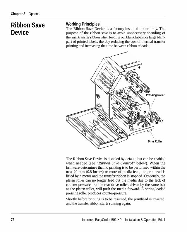
Intermec EasyCoder 501 XP – Installation & Operation Ed. 172
Chapter 8 Options
Ribbon Save Device
Working PrinciplesThe Ribbon Save Device is a factory-installed option only. The purpose of the ribbon save is to avoid unnecessary spending of thermal transfer ribbon when feeding out blank labels, or large blank part of printed labels, thereby reducing the cost of thermal transfer printing and increasing the time between ribbon reloads.
The Ribbon Save Device is disabled by default, but can be enabled when needed (see “Ribbon Save Control” below). When the fi rmware determines that no printing is to be performed within the next 20 mm (0.8 inches) or more of media feed, the printhead is lifted by a motor and the transfer ribbon is stopped. Obviously, the platen roller can no longer feed out the media due to the lack of counter pressure, but the rear drive roller, driven by the same belt as the platen roller, will push the media forward. A spring-loaded pressing roller produces counter-pressure.
Shortly before printing is to be resumed, the printhead is lowered, and the transfer ribbon starts running again.
Load
Drive Roller
Pressing Roller

Intermec EasyCoder 501 XP – Installation & Operation Ed. 1 73
Chapter 8 Option
Each operation of lifting and lowering the printhead takes 10+2=12 mm (0.5 inches) of media/ribbon feed; that is, at a non-printed area of 20 mm, the actual saving of ribbon will be 8 mm, and at a non-printed area of 50 mm, the saving will be 38 mm.
To facilitate media reload, the pressing roller is coupled to the headlift so the pressure is released when the printhead is lifted and the media can be routed between the rear drive roller and the pressing roller.
Ribbon Save ControlThe ribbon save device can be enabled or disabled in the Set Mode of the Stand-Alone program (Set\Setup\More\RIB), see the Intermec Stand-Alone Concept, Operating Instructions.
When the printer is fitted with a Ribbon Save Device, that is switched off, it is recommended not to pull back the media, for example by setting up negative Start Adjust values. Pulling back the media increases the risk of ribbon wrinkling and unsatisfactory printout quality. In case pull back cannot be avoided, test fi rst! Note that this restriction does not apply when the Ribbon Save Device is switched on.
Transfer RibbonsGeneral Purpose (GP) ribbons are coated with a wax-based “ink” that is more subject to smearing than the wax/resin-based “ink” of High Performance (HP) ribbons. Certain combinations of GP ribbons and thick and/or coarse receiving paper in connection with Ribbon Save may result in a somewhat smudged printout quality. As a possible remedy, a change to HP ribbons is recommended.
Ribbon Save Device, cont.

Intermec EasyCoder 501 XP – Installation & Operation Ed. 174
Chapter 8 Options
Ribbon/Media Low Sensor Kit
As an option, the EasyCoder 501 SA can be fi tted with two sensors, which detect the rotation of the media supply hub and the ribbon supply hub and update two counters, one for each sensor. Using custom-made application programs, the counters can be read and used to indicate media-low and ribbon-low conditions (as opposed to out-of-paper-out and out-of-ribbon conditions, which are supported by the standard error handling). See SYSVAR in Intermec Fingerprint v6.14, Reference Manual. The Intermec Stand-Alone program does not support these sensors.
The sensors require no regular cleaning. However, should any malfunction occur, you may try to blow the sensors clean from dust before calling for service.
The sensitivity of the sensors cannot be adjusted.
Ribbon Low Sensor
Media Low Sensor

Intermec EasyCoder 501 XP – Installation & Operation Ed. 1 75
Chapter 8 Option
Clear Door Panel As standard, the EasyCoder 501 SA is fi tted with a solid door on its right side. This door can easily be replaced by a door with a clear panel that makes it possible to check the media supply without opening the door.
Remove the existing door by opening it and pressing it forward until the snap-lock at the rear hinges becomes disengaged. Remove the door from the hinges and fi t the new door in reverse order.
Clear Panel
The EasyCoder 501 SA has one serial interface port ("uart1:"), see Appendix 4. In addition to this port, the printer can be fi tted with the following optional interface boards:
• Serial Interface Board 2 × RS-232 or 1 × RS-232 + 1 × 20 mA CL
• RS-422/485 Interface Board 1 × RS-422 + 1 × RS-232 or 1 × RS-485 + 1 × RS-232
• Parallel Interface Board 1 × Centronics
• Industrial Interface Board 1 × RS-232 + 4 × IN ports + 4 × OUT ports
Please refer to Appendix 4 for more information.
Interface Boards

Intermec EasyCoder 501 XP – Installation & Operation Ed. 176
Chapter 9
Symptom Possible Cause Remedy Refer toOverall weak printout Wrong Paper Type parameter Change parameter Chapter 6 Contrast value too low Change parameter Chapter 6 Printhead pressure too low Adjust both knobs Chapter 11 Worn printhead Replace printhead Chapter 10 Wrong printhead voltage Replace CPU board ☎ Call Service
Printout weaker on one side Uneven printhead pressure Adjust outer knob Chapter 11
Weak spots Foreign particles on media or ribbon Clean or replace Chapters 4 & 5 Media/ribbon don’t match Change to matching media Chapter 6 Poor media or ribbon quality Use Intermec media/ribbon Appendix 2 Worn printhead Replace printhead Chapter 10 Worn platen roller Check/replace ☎ Call Service
Overall dark printout Wrong Paper Type parameter Change parameter Chapter 6 Contrast value too high Change parameter Chapter 6 Printhead pressure too high Adjust Chapter 11 Wrong printhead voltage Replace CPU board ☎ Call Service
Excessive bleeding Wrong Paper Type Change parameter Chapter 6 Contrast value too high Change parameter Chapter 6 Printhead pressure too high Adjust both knobs Chapter 11 Faulty energy control Replace CPU board ☎ Call Service
Dark lines along media path Foreign objects on printhead Clean printhead Chapter 10
White lines along media path Printhead dirty Clean printhead Chapter 10 Missing dots on printhead Replace printhead Chapter 10
Large part of dot line missing Wrong X-start or Width parameter Change parameter Chapter 6 Failing printhead Replace printhead Chapter 10 Failing strobe signal Check CPU-board ☎ Call Service
Last part of print image missing Too small image buffer Increase buffer size Chapter 6
Printout missing along inner edge Bad media alignment Adjust Chapter 4 X-start parameter value too low Increase Chapter 6
Transfer ribbon breaks Ribbon not fi tted correctly Reload ribbon Chapter 5 Wrong paper type parameter (too much Change parameter, Chapter 6 energy) then clean printhead Chapter 11 Ribbon supply hub stuck Adjust ☎ Call Service Bad energy control Adjust ☎ Call Service
Transfer ribbon wrinkles Ribbon supply hub not centered Adjust Chapter 11 Ribbon obstructed by printhead cable Clear n.a. Incorrect edge guide adjustment Adjust Chapter 4 Too strong printhead pressure Adjust Chapter 11
No thermal transfer printout Ink-coated side does not face media Reload ribbon Chapter 5
Media feed not working properly Changed media characteristics Perform a TESTFEED Chapter 4 Wrong start- and stop adjust values Check/change Chapter 6 Wrong Media Type parameter Check/change Chapter 6 Wrong sensor position Check/change Chapter 11 Dirty or blocked LSS Clean Chapter 10 Faulty sensors Replace ☎ Call Service
Troubleshooting
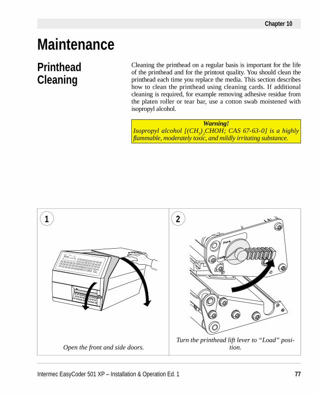
Intermec EasyCoder 501 XP – Installation & Operation Ed. 1 77
Chapter 10
MaintenancePrinthead Cleaning
Cleaning the printhead on a regular basis is important for the life of the printhead and for the printout quality. You should clean the printhead each time you replace the media. This section describes how to clean the printhead using cleaning cards. If additional cleaning is required, for example removing adhesive residue from the platen roller or tear bar, use a cotton swab moistened with isopropyl alcohol.
Warning!Isopropyl alcohol [(CH
3)
2CHOH; CAS 67-63-0] is a highly
fl ammable, moderately toxic, and mildly irritating substance.
1 2
Open the front and side doors.Turn the printhead lift lever to “Load” posi-
tion.
∆∆
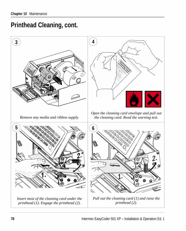
Intermec EasyCoder 501 XP – Installation & Operation Ed. 178
Chapter 10 Maintenance
2. 2.2.
1.1.
∆∆
6
Printhead Cleaning, cont.
Remove any media and ribbon supply.Open the cleaning card envelope and pull out
the cleaning card. Read the warning text.
3 4
Pull out the cleaning card (1) and raise the printhead (2).
Insert most of the cleaning card under the printhead (1). Engage the printhead (2).
5
Cleaning Card
This pre-saturated disposable Thermal Printer Cleaning Card is
designed to safely and effectively remove all dirt, ink, tape,
residue, adhesive and other contaminants from Thermal Print Heads.
This Cleaning card will improve print quality and the life of the
Thermal Print Head.
NOTE: For Thermal Transfer Printers, remove ribbon.
• Open pouch and remove EasyCoder Cleaning Card.
• Lift thermal printhead and insert EasyCoder Cleaning Card.
Lower printhead and press FEED or PRINT. If printer returns
an error message, repeat the procedure but press FEED
or PRINT before lowering the printhead. The printer will start
feeding after printhead is lowered.
• Allow a few seconds for EasyCoder Cleaning Card to dry,
then insert dry card for a second time, feed to remove remaining
contamination.
• Remove Cleaning Card and dispose of properly.
• Use EasyCoder Cleaning Cards before inserting every roll of label
stock or ticket stock.
– Works on all EasyCoder Printers –
Directions
RECOMMENDED USAGE:
SAFE • EASY • EFFECTIVE
PROTECTS YOUR EQUIPMENT
LoaL

Intermec EasyCoder 501 XP – Installation & Operation Ed. 1 79
Chapter 10 Maintenance
∆∆
2.
9
5
Printhead Cleaning, cont.
Wait for approx. 30 seconds to allow the clean-ing fl uid to dissolve the residue.
Insert most of the cleaning card under the printhead (1). Engage the printhead (2).
Pull out the cleaning card. If necessary, repeat the process with a fresh cleaning card.
7
10
Allow the cleaned parts to dry before loading any media and ribbon.

Intermec EasyCoder 501 XP – Installation & Operation Ed. 180
Chapter 10 Maintenance
1
External Cleaning
Always remove the power cordbefore cleaning!
Wipe external surfaces with a soft cloth slightly moistened with water or a mild detergent.
3
Never use any sharp tools for removing stuck labels. The printhead and rollers are delicate.
Never spray the printer. Protect it from water when cleaning the premises.
2
4
∆∆
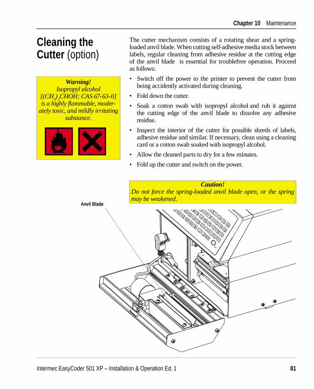
Intermec EasyCoder 501 XP – Installation & Operation Ed. 1 81
Chapter 10 Maintenance
The cutter mechanism consists of a rotating shear and a spring-loaded anvil blade. When cutting self-adhesive media stock between labels, regular cleaning from adhesive residue at the cutting edge of the anvil blade is essential for troublefree operation. Proceed as follows:
• Switch off the power to the printer to prevent the cutter from being accidently activated during cleaning.
• Fold down the cutter.
• Soak a cotton swab with isopropyl alcohol and rub it against the cutting edge of the anvil blade to dissolve any adhesive residue.
• Inspect the interior of the cutter for possible shreds of labels, adhesive residue and similar. If necessary, clean using a cleaning card or a cotton swab soaked with isopropyl alcohol.
• Allow the cleaned parts to dry for a few minutes.
• Fold up the cutter and switch on the power.
Caution!Do not force the spring-loaded anvil blade open, or the spring may be weakened.
Anvil Blade
Cleaning the Cutter (option)
Warning!Isopropyl alcohol
[(CH 3)
2CHOH; CAS 67-63-0]
is a highly fl ammable, moder-ately toxic, and mildly irritating
substance.
∆∆

Intermec EasyCoder 501 XP – Installation & Operation Ed. 182
Chapter 10 Maintenance
Cleaning the Ribbon Save Device (option)
In the optional ribbon save print device, the label stop/black mark sensor (LSS) is partially enclosed by two black plastic guide plates. These have been added to prevent thin receiving media from getting jammed when pushed forward by the rear drive roller at the time when the printhead is lifted.
The guide plates can easily be removed for cleaning. First, pull the upper guide straight out. Then, press the snap-lock of the lower guide by means of a coin or screwdriver and lift the outer end free before carefully pulling the guide plate out.
Both guide plates are provided with seemingly opaque, smooth windows, which actually are transparent to the light of the LSS. These windows must be kept clean from dust, stuck labels and adhesive residue. Only use isopropyl alcohol for cleaning.
When putting back the guide plates, start with the lower one and insert the two studs on the inner side into the corresponding holes in the inner gable. Then press down the outer end so the snap-lock fi ts into the slot in the outer gable.
The upper guide is threaded onto the beam of the LSS and connects to the lower guide by means of a pin and a metallic snap-lock.
Do not use excessive force when removing or fi tting the guide plates!
When needed, the rear rollers can be cleaned using a blotting paper or soft cloth slightly moistened with isopropyl alcohol.
Warning!Isopropyl alcohol
[(CH 3)
2CHOH; CAS 67-63-0]
is a highly fl ammable, moder-ately toxic, and mildly irritating
substance.
Snap-Lock
Stud
Snap-Lock
Lower Guide
Upper Guide
LSS Window
The upper part of the print unit has been omitted to improve the view of the guides!

Intermec EasyCoder 501 XP – Installation & Operation Ed. 1 83
Chapter 10 Maintenance
Printhead Replacement
The quick-mount thermal printhead is easy to replace:
• Switch off the printer.
• Open the front and right-hand doors.
• Lift the printhead and remove the media and ribbon.
• Rotate the printhead lock handle counterclockwise to open position, see illustration.
• Remove the printhead assembly carefully as far as the cables allow.
• Remove the two printhead cables by pulling at the connectors.
• If you want to change the lateral position of the printhead, move the #T20 Torx screw to its alternative position.
• Connect the two cables to the printhead.
• Fit the replacement printhead assy back into the bracket so the guide screw fi ts into its slot and the rear end of the assy is held by the two lugs.
• Rotate the locking handle clockwise to locked position.
• Load media and ribbon. Then engage the printhead.
• Switch on the power. At power-up, the printer will automatically reset itself to the characteristics of the printhead in regard of head resistance.
Lug
Guide Screw
SlotLug
Open Position
Lock Handle
Locked Position
Alternative positionfor guide screw
Printhead assy
Slot (for alternativeposition of guide screw)

Intermec EasyCoder 501 XP – Installation & Operation Ed. 184
Chapter 11
Position Adjustment (standard print unit)The label stop sensor (LSS) controls the media feed by detecting gap between labels, slots in continuous stock, or black marks at the back of continuous stock. Also see Chapter 6, “Setting Up the Printer.”
The label stop sensor can be moved sideways across the media path. The position can be changed continuously from the inner edge of the media and up to 50 mm (1.97 inches) outwards. The inner edge of the handle indicates the detection position. Always adjust the position of the LSS so it corresponds to the center of black marks or slots. In case of irregularly shaped labels, adjust the position so it corresponds to the front tip of the label.
Label Stop Sensor
Adjustments
Handle
Adjustment 0-50 mm (0-1.97 in)
Point of Detection
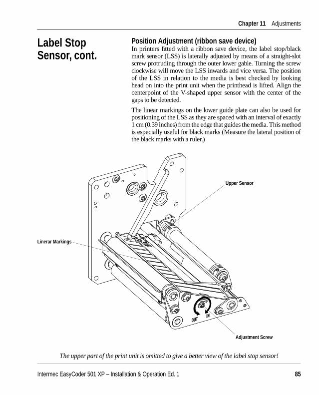
Intermec EasyCoder 501 XP – Installation & Operation Ed. 1 85
Chapter 11 Adjustments
Label Stop Sensor, cont.
Position Adjustment (ribbon save device)In printers fi tted with a ribbon save device, the label stop/black mark sensor (LSS) is laterally adjusted by means of a straight-slot screw protruding through the outer lower gable. Turning the screw clockwise will move the LSS inwards and vice versa. The position of the LSS in relation to the media is best checked by looking head on into the print unit when the printhead is lifted. Align the centerpoint of the V-shaped upper sensor with the center of the gaps to be detected.
The linear markings on the lower guide plate can also be used for positioning of the LSS as they are spaced with an interval of exactly 1 cm (0.39 inches) from the edge that guides the media. This method is especially useful for black marks (Measure the lateral position of the black marks with a ruler.)
The upper part of the print unit is omitted to give a better view of the label stop sensor!
OUT IN
Upper Sensor
Adjustment Screw
Linerar Markings

Intermec EasyCoder 501 XP – Installation & Operation Ed. 186
Chapter 11 Adjustments
Label Stop Sensor, cont.
Sensitivity AdjustmentThe sensitivity of the label stop sensor can be adjusted in three ways:• Fine-adjustment can be performed by pressing the <Feed> key. • The intensity of the LSS emitter can be adjusted in the Setup
Mode (see below).• The sensitivity of the LSS receiver can be adjusted using a
potentiometer on the CPU board, see Appendix 3.
Adjusting the LSS in the Setup ModeThe intensity of the LSS emitter can be adjusted in the Detection part of the Setup Mode:
LABEL <> GAP ■
• Often it will suffi ce just to perform a couple of TESTFEED operations by pressing <Feed>, which allows the printer to auto-adjust itself. A blank label (or the equivalent) will be fed out. When the media feed works as expected, you can exit the LSS adjustment by pressing <Enter>.
• If you cannot make the media feed work properly using TEST-FEEDs, you will have to adjust the LSS as described below. Before the LSS is adjusted, the printer must be set for the type of media you intend to use, that is, Label (w gaps), Ticket (w mark), Ticket (w gaps), Fix length strip, or Var. length strip.
• You can check the present value of the LSS by pressing the <Ins> key. The value will be displayed at the center of the menu, for example:
LABEL <103> GAP ■
• Press < Ins > again and the value disappears. This facility can be used any time during the LSS setup operation.

Intermec EasyCoder 501 XP – Installation & Operation Ed. 1 87
Chapter 11 Adjustments
❑ Label (w gaps) Put a piece of labels with liner between the two parts of the sensor.
The cursor should appear at the left side of the menu:
LABEL <103> GAP ■
Put a piece of liner without any label into the sensor. The cursor should move to the center of the menu:
LABEL <103> GAP ■
Finally remove any from the sensor. The cursor should move to the right side of the menu:
LABEL <103> GAP ■
❑ Ticket (w mark) Put the media between the two parts of the sensor, making sure
there is no black mark close to the LSS. The cursor should appear at the right side of the menu:
MARK <103>TICKET ■
Move the media so the black mark becomes situated above the sensor. The cursor should move to the left side of the menu (the same applies when no media is loaded):
MARK <103>TICKET ■
❑ Ticket (w gaps), Fix Length Strip, and Var. Length Strip Put the media between the two parts of the sensor, making sure
there is no gap close to the LSS. The cursor should appear at the left side of the menu:
LABEL <103> GAP ■
In case of tickets, move the media so the gap becomes situated above the sensor. In case of strip, remove the media completely.
In both cases, the cursor should move to the left side of the menu:
LABEL <103> GAP ■
Label Stop Sensor, cont.
Intermec EasyCoder 501 XP – Installation & Operation Ed. 188
Chapter 11 Adjustments
❑ If the cursor is not situated correctly, the LSS must be adjusted.
• The LSS emitter can be set to a value between 0 and 127. Try to fi nd the correct level by means of the following keys:
Del decreases the level 1 step. Esc increases the level 1 step. ← decreases the level 10 steps. → increases the level 10 steps. Keep trying until you fi nd the right level.
• When the adjustment looks right, press <Feed>. This will produce a TESTFEED, that is, it will allow the printer feed out one label, ticket, tag, or piece of strip in order to adjust itself and to allow you to check that the media feed works correctly. At least two TESTFEEDs should be produced before you go on.
• If you cannot make the LSS work correctly by following the instructions above, you may–as a last resort–need to adjust the potentiometer on the CPU board, see Appendix 3. Read the instructions carefully before starting, since you will be working in a part of the printer with live high-voltage components!
• Try different combinations of potentiometer settings and LSS levels until the cursor is positioned correctly.
• When you are satisfi ed that the LSS is set up correctly, press <Enter>. That will set the LSS and let you proceed to next part of the Detection setup, see Chapter 7.
Label Stop Sensor, cont.

Intermec EasyCoder 501 XP – Installation & Operation Ed. 1 89
Chapter 11 Adjustments
The contrast of the printer’s display can be adjusted using a potentiometer, which is situated close to the connector of "uart1:". It can be accessed through a small hole in the rear plate. Using a narrow-tipped screwdriver, turn the screw in either direction until the text in the LCD display on the printer’s front becomes clearly visible in the prevailing light conditions when viewed from a normal working position.
Display Contrast
Display Contrast Adjustment

Intermec EasyCoder 501 XP – Installation & Operation Ed. 190
Chapter 11 Adjustments
+-
+-
Printhead Pressure
At printing, the thermal printhead must be pressed against the platen roller so the heat can be transferred to the media. There must also be enough pressure to provide a suffi cient amount of friction between the media and the platen roller that drives the media. Too weak pressure gives a weak printout quality, whereas too strong pressure may cause unnecessary wear of the printhead.
The pressure is factory adjusted, but special applications may require readjustment using the trial-and-error method. Do not use more pressure than necessary to obtain the desired printout quality.
The print unit is fi tted with two adjustable spring packages, which allow the pressure to be set by turning the knobs:• Turn the knobs clockwise to increase the pressure.• Turn the knobs counter-clockwise to decrease the pressure.
At each quarter of a turn, the resistance increases and a clicking sound can be heard.
The required pressure may vary between media of different thickness. Generally, thicker media require more pressure than thinner.
Make a rough adjustment like this:• Turn both adjustment knobs clockwise as far as they go to
maximum pressure.• Release the pressure of the inner spring package by turning the
knob 2 1/4 turns counter-clockwise (9 clicks).• Release the pressure of the outer spring package by turning the
knob 2 turns counter-clockwise (8 clicks).
Fine-adjust the pressure by turning the outer knob, while retaining the setting of the inner knob. If the desired result cannot be obtained, increase or decrease the pressure by turning both knobs a quarter of a turn in the same direction, then fi ne-adjust the outer knob.
Adjustment Knobs

Intermec EasyCoder 501 XP – Installation & Operation Ed. 1 91
Appendix 1
PrintingPrint Technique Direct Thermal and Thermal Transfer1 Printhead Resolution 8 or 11.81 dots/mm (203.2 or 300 dpi) Quick-mount printheadPrint Speed (max) 100 to 200 mm/sec. (≈ 4 to 8 inches/sec.)Print Width (8/11.81 dots/mm ), max. 104 mm (4.09 inches)/108.3 mm (4.26 inches) = 832/1280 dotsPrint Length (8/11.81 dots/mm ) 1,250 mm (49.2 inches)/833 mm (32.8 inches) Media Width (max) 120 mm (4.7 inches) Media Roll Diameter (max) 205 mm (8.0 inches) Internal rollMedia Roll Core Diameter 38 to 40 mm (1.5 inches) or 76 mm (3 inches)Ribbon Length, max 450 m (1,476 ft.) Intermec ribbonsRibbon Width (max) 110 mm (4.3 inches)Print Directions 4Label Slack Absorber YesModes of OperationTear-Off (Straight-through) YesCut-Off Option With cutterPeel-Off (Self-strip) Option With liner takeupInternal Batch Takeup Option With liner takeupFirmwareOperating System Intermec Fingerprint v6.14 Incl. Direct ProtocolBuilt-in bitmap fonts (std) 10 Expandible 4 timesBuilt-in bar code symbologies (std) 10Startup Program (std) Intermec Stand-Alone ConceptPhysical MeasuresDimensions (W x L x H) 275 x 480 x 239 mm (10.8 x 18.9 x 9.04 inches) Without cutterWeight (excluding media and options) ≈ 15.0 kg (33 pounds)Ambient Operating Temperature +5°C to +40°C (+41°F to +104°F)Humidity 20 to 80% non-condensingSound Emission Level <60 dB(A)ElectronicsMicroprocessor 32 bit RISCOn-board RAM memory Std. 512 Kbytes; Max. 2MB1
Real Time Clock (RTC) Yes Power SupplyInput Voltage 115/230 VAC (+10%/-15%), 2.6/1.3A, 60/50 Hz Manual switch Maximum Power Consumption 300W
Technical Data

Intermec EasyCoder 501 XP – Installation & Operation Ed. 192
Appendix 1 Technical Data
SensorsLabel Gap/Black Mark/Out of Media Yes Variable positionRibbon End YesPrinthead Lifted YesControlsControl Lamps 3Display 2 x 16 character LCD Keyboard Full QWERTY membrane-switch typeBeeper YesData InterfacesSerial 1 x RS-232 (prepared for RS-4222 or 20 mA CL2) Connection for Optional Interface Board 1 Accessories and OptionsPaper Cutter Option2
Memory Card Adapter Option2 Label Taken Sensor Option2
Ribbon Save Device Option4
Sensor Kit Option2 Ribbon low/Media lowParallel Interface Board Option2
Double Serial Interface Board Option2
RS-422/485 Serial Interface Board Option2
Industrial Interface Board Option2
Liner Takeup Unit Option4 Incl. batch takeup guideMedia Roll Retainer Option3
External Supply Guides Option3
RS-232 Cable Option3
Parallel Interface Cable Option3
External Alphanumeric Keyboard Option3
Clear Door Panel Option2 For view of media roll1/. Pure direct thermal confi guration is only available as a factory-installed option.2/. Available as factory installed option or fi eld-installable kit.3/. Field-installable option only.4/. Factory-installable option only.
Technical Data, cont.
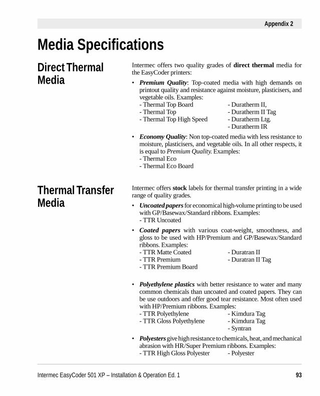
Intermec EasyCoder 501 XP – Installation & Operation Ed. 1 93
Appendix 2
Media Specifi cationsDirect Thermal Media
Intermec offers two quality grades of direct thermal media for the EasyCoder printers:
• Premium Quality: Top-coated media with high demands on printout quality and resistance against moisture, plasticisers, and vegetable oils. Examples:
- Thermal Top Board - Duratherm II, - Thermal Top - Duratherm II Tag - Thermal Top High Speed - Duratherm Ltg. - Duratherm IR
• Economy Quality: Non top-coated media with less resistance to moisture, plasticisers, and vegetable oils. In all other respects, it is equal to Premium Quality. Examples:
- Thermal Eco - Thermal Eco Board
Intermec offers stock labels for thermal transfer printing in a wide range of quality grades.
• Uncoated papers for economical high-volume printing to be used with GP/Basewax/Standard ribbons. Examples:
- TTR Uncoated
• Coated papers with various coat-weight, smoothness, and gloss to be used with HP/Premium and GP/Basewax/Standard ribbons. Examples:
- TTR Matte Coated - Duratran II - TTR Premium - Duratran II Tag - TTR Premium Board
• Polyethylene plastics with better resistance to water and many common chemicals than uncoated and coated papers. They can be use outdoors and offer good tear resistance. Most often used with HP/Premium ribbons. Examples:
- TTR Polyethylene - Kimdura Tag - TTR Gloss Polyethylene - Kimdura Tag - Syntran
• Polyesters give high resistance to chemicals, heat, and mechanical abrasion with HR/Super Premium ribbons. Examples:
- TTR High Gloss Polyester - Polyester
Thermal Transfer Media

Intermec EasyCoder 501 XP – Installation & Operation Ed. 194
Appendix 2 Media Specifi cations
Media Roll Size
CoreDiameters: 38-40 mm (1.5 inches) or 76.2 mm (3 inches) Width: Must not protrude outside the media.
The media must be wound up on the core in such a way that the printer can pull the end free.
RollMax. diameter (internal roll): 205 mm (8.00 inches)Max. width: 120 mm (4.72 inches)Min. width: 25.4 mm (1.00 inches)Max. web thickness: 175 µm (0.007 inches)
The maximum recommended media thickness is 175µm. Thicker media may be used, but print quality will be reduced. The stiffness is also important and must be balanced against thickness to maintain print quality.
Caution!Any external media supply should be well protected against sand, grit, etc. Even very small but hard particles may cause severe harm to the printhead.
Width:Max. 120.0 mm (4.7 in)Min. 25.4 mm (1.0 in)
Printableside
orlabels
Core diameter:38-40 mm (1.5 in-1.6 in)or76.2 mm (3 in)
Roll diameter:Max. 205 mm (8 in)

Intermec EasyCoder 501 XP – Installation & Operation Ed. 1 95
Appendix 2 Media Specifi cations
Non-Adhesive Strip
Media
⇐ a ⇒ Media WidthMaximum: 120.0 mm (4.72 inches)Minimum: 25.4 mm (1.00 inches)
Media Type Setup• Fix length strip• Var length strip

Intermec EasyCoder 501 XP – Installation & Operation Ed. 196
Appendix 2 Media Specifi cations
Media, cont.
⇐ a ⇒ Media Width (including liner)Maximum: 120.0 mm (4.72 inches)Minimum: 25.4 mm (1.00 inches)
⇐ b ⇒ LinerThe liner must not extend more than a total of 1.6 mm (0.06 inches) outside the face material and should protrude equally on both sides.
⇐ c ⇒ Media Width (excluding liner)Maximum: 118.4 mm (4.66 inches)Minimum: 23.8 mm (0.94 inches)
Media Type Setup• Fix length strip• Var length strip
This type of media is not suitable for use with a cutter.
Self-Adhesive Strip

Intermec EasyCoder 501 XP – Installation & Operation Ed. 1 97
Appendix 2 Media Specifi cations
Media, cont.
⇐ a ⇒ Media Width (including liner)Maximum: 120.0 mm (4.72 inches)Minimum: 25.4 mm (1.00 inches)
⇐ b ⇒ LinerThe liner must not extend more than a total of 1.6 mm (0.06 inches) outside the labels and should protrude equally on both side. Recommended min. transparency: 40% (DIN 53147).
⇐ c ⇒ Label Width (excluding liner)Maximum: 118.4 mm (4.66 inches)Minimum: 23.8 mm (0.94 inches)
⇐ d ⇒ Label LengthMaximum (8 dots/mm)1: 1875 mm (73.8 inches)Maximum (11.81 dots/mm)1: 1250 mm (49.2 inches)Minimum (all): 10 mm (0.39 inches)
⇐ e ⇒ Label GapMaximum: 10.0 mm (0.39 inches)Recommended: 1.6 mm (0.06 inches)Minimum: 1.2 mm (0.05 inches)
The adjustable label stop sensor must be able to detect the extreme front and rear edges of the labels. Therefore, do not use a larger inner core radii than can be compensated for by adjusting the sensor’s position, that is, approximately 50 mm (1.97 inches).
Media Type Setup• Label (w gaps)
Self-Adhesive Labels
a
b
c
e
SELF-ADHESIVELABELS
b
d
FEEDDIRECTION
1/. The last third of a label (or the equivalent) cannot be used for printing, that is, the maxi-mum print length is 1250 mm (49.2 inches) at 8 dots/mm and 833 mm (32.8 inches) at 11.81 dots/mm.

Intermec EasyCoder 501 XP – Installation & Operation Ed. 198
Appendix 2 Media Specifi cations
Media, cont.
Tickets with Gap ⇐ a ⇒ Media WidthMaximum: 120.0 mm (4.72 inches)Minimum: 25.4 mm (1.00 inches)
⇐ b ⇒ Copy LengthMaximum (8 dots/mm)1: 1875 mm (73.8 inches)Maximum (11.81 dots/mm)1: 1250 mm (49.2 inches)Minimum (all): 10 mm (0.39 inches)
⇐ c ⇒ Detection Slit StartThe restriction of the minimum slit length must be observed and the slit must not break the inner edge of the media.
⇐ d ⇒ Detection Slit LengthThe length of the detection slit (excluding corner radii) must be minimum 5.0 mm (0.20 inches).
⇐ e ⇒ Detection Slit EndProvided the restrictions of the minimum slit length and slit start are observed, the distance from the inner edge of the media to the outer end of the slit (excluding corner radius) may be maximum 50 mm (1.97 inches).
⇐ f ⇒ Detection Slit HeightMaximum: 10.0 mm (0.39 inches)Recommended: 1.6 mm (0.06 inches)Minimum: 1.2 mm (0.05 inches)
PerforationDo not allow any perforation to break the edge of the media as this may cause the media to split and jam the printer.
Media Type Setup• Ticket (w gaps)
a
TICKETS & TAGS
e
FEEDDIRECTION
b
fd
c
1/. The last third of a label (or the equivalent) cannot be used for printing, that is, the maxi-mum print length is 1250 mm (49.2 inches) at 8 dots/mm and 833 mm (32.8 inches) at 11.81 dots/mm.

Intermec EasyCoder 501 XP – Installation & Operation Ed. 1 99
Appendix 2 Media Specifi cations
Media, cont.
Tickets with Black Mark ⇐ a ⇒ Media WidthMaximum: 120.0 mm (4.72 inches)Minimum: 25.4 mm (1.00 inches)
⇐ b ⇒ Copy LengthMaximum (8 dots/mm)1: 1875 mm (73.8 inches)Maximum (11.81 dots/mm)1: 1250 mm (49.2 inches)Minimum (all): 10 mm (0.39 inches)
⇐ c ⇒ Black Mark OffsetMax. offset: 40 mm (1.57 inches)Min. offset: 0 mm (0.0 inches)
⇐ d ⇒ Black Mark WidthMinimum detectable width: 10 mm (0.4 inches)
⇐ e ⇒ Black Mark EndNo restriction, but the LSS cannot detect the mark more than 50 mm (1.97 inches) from the inner edge of the media.
⇐ f ⇒ Black Mark HeightCommonly used height: 12.5 mm (0.5 inches)Minimum: 5.0 mm (0.2 inches)
⇐ g ⇒ Black Mark Y-PositionIt is recommended to place the black mark as close to the front edge of the ticket as possible and use a negative Stop Adjust value to control the media feed, so the tickets can be properly torn or cut off (see Chapter 6).
PerforationIt is recommended not to allow possible perforation to break the edges of the media. Else there is a small risk that the web may be partly separated before printing, causing a media jam.
Black Mark ColorThe mark should be non-reflective carbon black on a whitish background.
Important! Preprint that may interfere with the detection of the black mark should be avoided on the back of the media.
Media Type Setup• Ticket (w mark)
a
TICKETS
e
FEEDDIRECTION
f
dc g
b
1/. The last third of a label (or the equivalent) cannot be used for printing, that is, the maxi-mum print length is 1250 mm (49.2 inches) at 8 dots/mm and 833 mm (32.8 inches) at 11.81 dots/mm.

Intermec EasyCoder 501 XP – Installation & Operation Ed. 1100
Appendix 2 Media Specifi cations
Intermec offer three types of thermal transfer ribbons optimized for different purposes:
• General Purpose (GP)/Standard & Basewax transfer ribbons allow high speed printing and give a good printout, but are somewhat sensitive to smearing. They may be the best choice for uncoated and coated papers.
• High Performance (HP)/Premium transfer ribbons allow high speed printing and give a highly readable and defi ned printout on most face materials with smooth surfaces. They have good “smear resistance” and are most suitable for intricate logotypes and images on matte-coated papers and synthetic face materials.
• High Resistance (HR)/Super Premium transfer ribbons give an extremely durable printout, which is resistant to most chemical agents and high temperatures. However, such transfer ribbons set high demands on the receiving face material, which must be very smooth, such as polyesters.
The use of HR/Super Premium ribbons requires the print speed and the energy supplied by the printhead to be controlled with great accuracy according to the receiving face material. Custom-made setup options adapted for special applications can also be created. Consult your Intermec distributor.
Important!Intermec thermal transfer rib-bons are engineered specifi cally for the EasyCoder printheads.
Transfer Ribbons

Intermec EasyCoder 501 XP – Installation & Operation Ed. 1 101
Appendix 3
WARNING!Disconnect the power cord before removing the cover.Dangerous voltage!
CPU BoardThe CPU board is situated in the electronics compartment on the left side of the printer’s center section. To gain access to the electronics compartment, proceed as follows:• Switch off the printer and disconnect the power cord. The
CPU board contains power supply circuits with dangerous voltage.
• Remove the four #T10 Torx screws situated along the lower edge of the cover plate as indicated on the illustration below.
• Open the right-hand door and remove the four #T10 Torx screws at the top of the cover plate.
• Remove the cover plate.• Reassemble in reverse order.
Accessing the CPU Board
4 Screws
Cover Plate
4 Screws
∆∆

Intermec EasyCoder 501 XP – Installation & Operation Ed. 1102
Appendix 3 CPU Board
The CPU board contains a number of potentiometers for controlling various sensors. It also contains straps and circuits for setting the type of communication on the standard serial port "uart:", see Appendix 4.
Before touching the CPU board, carefully read this:• Check that the power on control lamp at the top/front corner of the
board is off. If not, disconnect the power cord.• Take precautions to prevent electrostatic discharge • Only use non-conductive tools. There is low-voltage power
on the CPU board even when the printer is switched off and disconnected.
The CPU board is fi tted with four potentiometers with the following functions:• Display contrast adjustment (see Chapter 11)• Label stop sensor (LSS) adjustment• Label taken sensor (LTS) adjustment• Ribbon end sensor (R-End) adjustment
Potentiometers
Safety Instructions
POWER ONLTSLSS R-END
P-607
Label Taken Sensor
Label Stop Sensor Ribbon End Sensor
Power On Indicator
Ribbon End Sensor Strap

Intermec EasyCoder 501 XP – Installation & Operation Ed. 1 103
Appendix 3 CPU Board
Three potentiometers are situated along the top edge of the CPU board and can only be accessed after the left-hand cover plate has been removed. Normally, they do not require any adjustment.
• Label Stop Sensor potentiometer This potentiometer is used in connection with the printer’s Setup
Mode for adjusting the sensitivity of the label stop sensor, for example according to the transparency of various brands of liner. In most cases, it will be suffi cient to use the adjustment method offered in the Setup Mode and by the Testfeed facility.
• Label Taken Sensor potentiometer The label taken sensor (optional) is situated above the media
outfeed slot and detects if a label has not been removed from the outfeed area. Thereby, the printer can be programmed not to print any more copies before the last copy has been removed. The operation of this sensor depends to a large extent on the refl ectivity of the labels (for example glossiness, color, etc.). Thus, it may sometimes require adjustment when switching between different types of labels.
The light intensity of the emitter can be changed between two values by means of fi tting or removing a strap on P-607 (strap fi tted = increased intensity).
• Ribbon End Sensor potentiometer The ribbon end sensor is situated at the rear part of the printing
mechanism. It emits a narrow beam of light and detects when there is no more thermal transfer ribbon left to stop the light from being refl ected back from the mirror plate. This sensor is factory-adjusted and should normally not require any further adjustment, except after possible replacement.
The light intensity of the emitter can be changed between two values by means of fi tting or removing a strap on P-604 (strap fi tted = increased intensity).
This sensor is omitted if the printer is not fi tted with any transfer ribbon mechanism.
Before changing the setting of a potentiometer, always make sure that the corresponding sensor is clean, free from obstructions (for example pieces of labels or adhesive residue), and properly aligned.
Potentiometers, cont.

Intermec EasyCoder 501 XP – Installation & Operation Ed. 1104
Appendix 4
InterfacesStandard Interface"uart1:"
"uart1:"
All EasyCoder 501 printer models are fi tted with a DB25pin male interface connector on their rear plates (communication port "uart1:"). This connector can be used for an RS-232, an RS-422, or a 20 mA current loop interface depending on how the CPU board is strapped. In the latter two cases, additional circuits must be fi tted. The confi guration of the connection cable is also important.
Refer to the Intermec Stand-Alone Concept, Operating Instructions for information on how to select a communication port for various purposes.
If the printer is ordered without any connection cable, a suitable cable can be procured locally and, if necessary, be modifi ed according to the pinout descriptions in this chapter.
Signals on the printer'scommunication port "uart1:"
UART is an abbreviation for Uni-versal Asynchronous Receiver and Transmitter
0
230V
GNDC
21
3456789
10111213
1514
16171819202122232425
GNDCTXD outRXD inRTS outCTS inDSR inGNDI
+20 mA CL 1-20 mA CL 1+TXD-TXD+20 mA CL 2
GNDC
-20 mA CL 2+RS-422 In
+5V Ext.-RS-422 In
+RXD+RS-422 Out
DTR out-RS-422 Out
-RXD
IMPORTANT!A shielded communication cable is required in order to comply with the FCC/DOC approval and to avoid the risk of interference to radio communications.

Intermec EasyCoder 501 XP – Installation & Operation Ed. 1 105
Appendix 4 Interfaces
Standard Interface "uart1:", cont.
RS-232 RS-232 is the most common interface for serial communication with computers over short distances. The transmission can only take place between one transmitter and one receiver. The most simple form of two-way communication only requires a 3-wire cable. The maximum transmission distance is about 10 to 15 metres (33 to 49 ft.) and the maximum transmission speed is 19,200 baud.
• An RS-232 circuit must be fi tted on IC-200 (fi tted as standard).• A jumper must be fi tted on uppermost position of P-202.• Any RS 422 circuit on IC-207, optocouplers on IC-205 and IC-206
(optional) and straps on P-204–P-209 are of no consequence.
The following hardware straps can be fi tted:
P-200 DTR-signalPin 1–2 DTR indicates printer turned on.Pin 2–3 A copy of the fl ow signal RTS is produced.
P-203 External 5 Volt1
Jumper fi tted connects +5V to pin 16. Caution! Max 200 mA.
1/. Caution! Be careful not to enable the external 5V uninten-tionally, which may cause harm to the terminal, PC, or other device connected to this port!
232CL422
"UA
RT1:
" P202
IC-200
P2033 2 1
P200
+- P-203 (external +5 VDC)
P-200 (DTR/RTS select)
IC-200 (RS-232 circuit)
P-202 (Interface select)

Intermec EasyCoder 501 XP – Installation & Operation Ed. 1106
Appendix 4 Interfaces
This diagram shows the confi guration of RS-232 cables between an EasyCoder 501 and a computer with either a DB-9pin or DB-25pin communication port. The cable should have a female DB-25pin connector at the printer side.
1/. If the communication cable is not confi gured to transmit any CTS signal to the printer, a permanent CTS signal will automatically be produced.2/. Requires a strap fi tted on P-203, see previous page.
Host EasyCoder 501 HostSignal DB-9 DB-25 Signal DB-25 DB-25 Signalhousing housing housing 1 shield 1 1 shieldRXD 2 2 TXD 2 3 RXDTXD 3 3 RXD 3 2 TXDCTS1 8 4 RTS 4 5 CTS1
RTS 7 5 CTS 5 4 RTS GND 5 7 Signal GND 7 7 GND 16 + 5V2 16DSR 6 20 DTR 20 6 DSR
Standard Interface "uart1:", cont.
RS-232, cont.

Intermec EasyCoder 501 XP – Installation & Operation Ed. 1 107
Appendix 4 Interfaces
RS-422 is a point-to-point interface for connection between one printer and one host computer over a distance of up to 1,200 metres (4,000 ft.) by use of a four-wire cable. The transmission is full duplex, that is, reception and transmission can take place simultaneously.
RS-422 requires an additional circuit and a number of straps to be fi tted on the CPU board:
RS-422 connection between host computer and printer.
Standard Interface "uart1:", cont.
RS-422
+ RS422 IN- RS422 IN
+ RS422 OUT- RS422 OUT
∆∆
232CL422
"UA
RT1:
" P202
IC-207
P203
P208P206P209P207P204P205
+-
P-203 (external +5 VDC)
P-202 (interface select)
P-204 to P-209 (comm. straps)
IC-207 (RS-422 circuit)
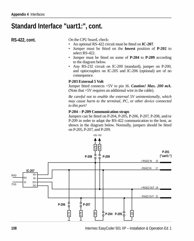
Intermec EasyCoder 501 XP – Installation & Operation Ed. 1108
Appendix 4 Interfaces
Standard Interface "uart1:", cont.
RS-422, cont. On the CPU board, check:• An optional RS-422 circuit must be fi tted on IC-207.• Jumper must be fi tted on the lowest position of P-202 to
select RS-422.• Jumper must be fi tted on some of P-204 to P-209 according
to the diagram below.• Any RS-232 circuit on IC-200 (standard), jumper on P-200,
and optocouplers on IC-205 and IC-206 (optional) are of no consequence.
P-203 External 5 VoltJumper fi tted connects +5V to pin 16. Caution! Max. 200 mA. (Note that +5V requires an additional wire in the cable).
Be careful not to enable the external 5V unintentionally, which may cause harm to the terminal, PC, or other device connected to this port!
P-204 – P-209 Communication strapsJumpers can be fi tted on P-204, P-205, P-206, P-207, P-208, and/or P-209 in order to adapt the RS-422 communication to the host, as shown in the diagram below. Normally, jumpers should be fi tted on P-205, P-207, and P-209.
IC-207
DI
RORI+RI-
DO+DO-
+ RS422 IN
- RS422 IN
+ RS422 OUT
- RS422 OUT
15
17
19
21
P-201("uart1:")
+5V +5V
P-208 P-209
P-206 P-207
P-204 P-205
/TXD
/RXD
4.7k
4.7k 100
100
4.7k
4.7k

Intermec EasyCoder 501 XP – Installation & Operation Ed. 1 109
Appendix 4 Interfaces
232CL422
"UA
RT1:
" P202
IC-205
IC-206
P203
+-
Standard Interface "uart1:", cont.
20 mA Current Loop The 20 mA current loop interface is a single-ended, full duplex serial interface which uses current instead of voltage to transmit signals on a four-wire line. 20 mA current corresponds to a logical “0” and 0 mA corresponds to a logical “1”.
Optocouplers are used to separate the transmission line from the internal logics of the printer and the host computer. Therefore this interface is suitable where electrical interference may occur, and for transmission over longer distances (up to 500 metres or 1,500 ft.).
Depending on the confi guration of the connection cable between printer and host computer, the printer can work either active (that is, supplying the current) or passive. A transmission speed between 300 and 9,600 baud is recommended.
P-203 (external +5 VDC)
IC-205 & IC-206 (optocouplers)
P-202 (interface select)

Intermec EasyCoder 501 XP – Installation & Operation Ed. 1110
Appendix 4 Interfaces
Standard Interface "uart1:", cont.
20 mA Current Loop, cont. On the CPU board, check:• Optocouplers must be fi tted on IC-205 and IC-206. These are not
included as standard and must be ordered separately.• Jumper must be fi tted on middle position of P-202 to select
20 mA current loop.• Any RS-422 circuit fi tted on IC-207 (optional), RS-232 circuit
fi tted on IC-200 (standard), and jumpers fi tted on P-204 to P-209 or on P-200 are of no consequence.
P-203 External 5 VoltJumper fi tted connects +5V to pin 16. Caution! Max. 200 mA.
Be careful not to enable the external 5V unintentionally, which may cause harm to the terminal, PC, or other device connected to this port!
Cable confi gurationThe printer end of the connection cable should have a DB-25pin female connector. The computer end of the cable depends on your type of computer.
The printer’s connector contains the following signals:Pin 9 + 20 mAPin 10 – 20 mAPin 11 TXD +Pin 12 TXD –Pin 13 + 20 mA*Pin 14 – 20 mA*Pin 16 + 5 VDC, 200 mA (if jumper fi tted on P-203)Pin 18 RXD +Pin 25 RXD –*. In case of printer being active receiver.
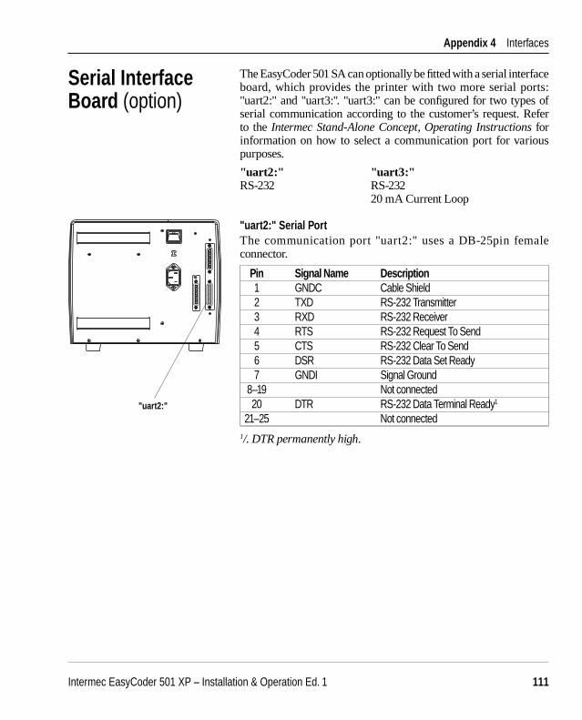
Intermec EasyCoder 501 XP – Installation & Operation Ed. 1 111
Appendix 4 Interfaces
The EasyCoder 501 SA can optionally be fi tted with a serial interface board, which provides the printer with two more serial ports: "uart2:" and "uart3:". "uart3:" can be confi gured for two types of serial communication according to the customer’s request. Refer to the Intermec Stand-Alone Concept, Operating Instructions for information on how to select a communication port for various purposes.
"uart2:" "uart3:"RS-232 RS-232 20 mA Current Loop
"uart2:" Serial PortThe communication port "uart2:" uses a DB-25pin female connector.
Pin Signal Name Description 1 GNDC Cable Shield 2 TXD RS-232 Transmitter 3 RXD RS-232 Receiver 4 RTS RS-232 Request To Send 5 CTS RS-232 Clear To Send 6 DSR RS-232 Data Set Ready 7 GNDI Signal Ground 8–19 Not connected 20 DTR RS-232 Data Terminal Ready1
21–25 Not connected1/. DTR permanently high.
Serial Interface Board (option)
"uart2:"
230V
0

Intermec EasyCoder 501 XP – Installation & Operation Ed. 1112
Appendix 4 Interfaces
"uart3:" Serial PortThe communication port "uart3:" uses a DB-25pin male connector.
Pin Signal Name Description 1 GNDC Cable Shield 2 TXD RS-232 Transmitter 3 RXD RS-232 Receiver 4 RTS RS-232 Request To Send 5 CTS RS-232 Clear To Send 6 DSR RS-232 Data Set Ready 7 GNDI Signal Ground 8 Not connected 9 +20M1 +20 mA current loop 10 -20M1 -20 mA current loop 11 +TXD +TXD 20 mA current loop 12 -TXD -TXD 20 mA current loop 13 +20M2 +20 mA current loop (printer active receiver) 14 -20M2 -20 mA current loop (printer active receiver) 15 Not connected 16 +5VEXT 5 VDC for external use (max. 200 mA)1
17 Not connected 18 +RxD +TXD 20 mA current loop 19 Not connected 20 DTR RS-232 Data Terminal Ready2
21–24 Not connected 25 -RxD -TXD 20 mA current loop
1/. Enabled by a strap being fi tted on P-6.2/. DTR permanently high.
Refer to the installation instructions for the Serial Interface Board for further information.
Serial Interface Board, cont.
"uart3:"
230V
0
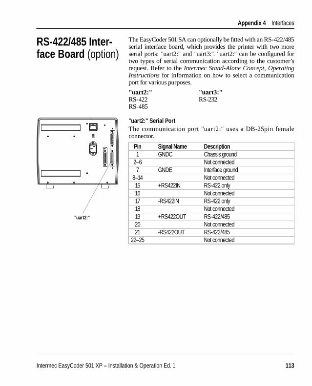
Intermec EasyCoder 501 XP – Installation & Operation Ed. 1 113
Appendix 4 Interfaces
The EasyCoder 501 SA can optionally be fi tted with an RS-422/485 serial interface board, which provides the printer with two more serial ports: "uart2:" and "uart3:". "uart2:" can be confi gured for two types of serial communication according to the customer’s request. Refer to the Intermec Stand-Alone Concept, Operating Instructions for information on how to select a communication port for various purposes.
"uart2:" "uart3:"RS-422 RS-232RS-485
"uart2:" Serial PortThe communication port "uart2:" uses a DB-25pin female connector.
Pin Signal Name Description 1 GNDC Chassis ground 2–6 Not connected 7 GNDE Interface ground 8–14 Not connected 15 +RS422IN RS-422 only 16 Not connected 17 -RS422IN RS-422 only 18 Not connected 19 +RS422OUT RS-422/485 20 Not connected 21 -RS422OUT RS-422/485 22–25 Not connected
RS-422/485 Inter-face Board (option)
"uart2:"
230V
0
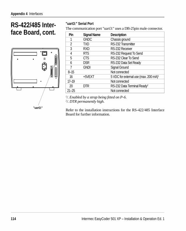
Intermec EasyCoder 501 XP – Installation & Operation Ed. 1114
Appendix 4 Interfaces
"uart3:" Serial PortThe communication port "uart3:" uses a DB-25pin male connector.
Pin Signal Name Description 1 GNDC Chassis ground 2 TXD RS-232 Transmitter 3 RXD RS-232 Receiver 4 RTS RS-232 Request To Send 5 CTS RS-232 Clear To Send 6 DSR RS-232 Data Set Ready 7 GNDI Signal Ground 8–15 Not connected 16 +5VEXT 5 VDC for external use (max. 200 mA)1
17–19 Not connected 20 DTR RS-232 Data Terminal Ready2
21–25 Not connected1/. Enabled by a strap being fi tted on P-6.2/. DTR permanently high.
Refer to the installation instructions for the RS-422/485 Interface Board for further information.
RS-422/485 Inter-face Board, cont.
"uart3:"
230V
0
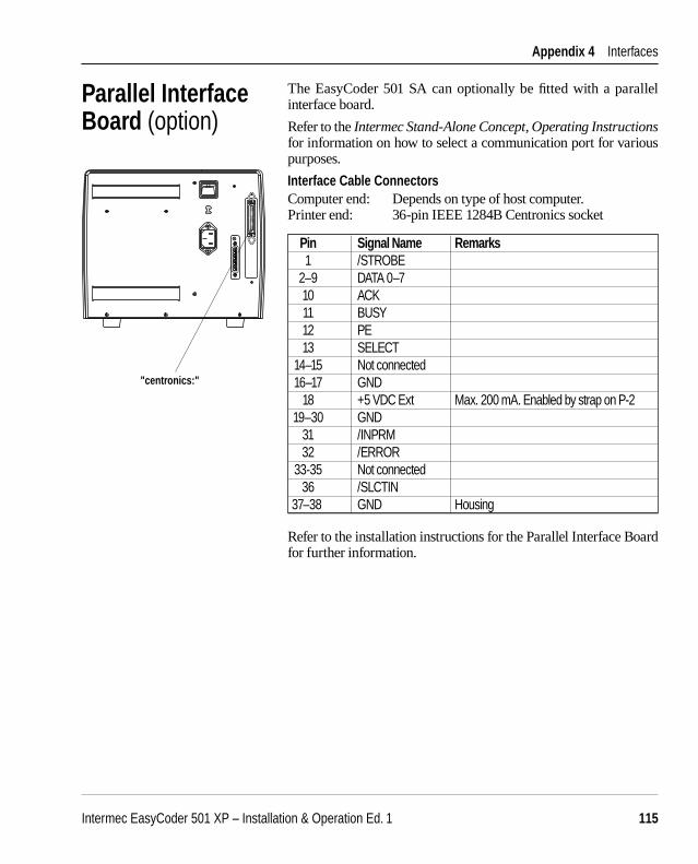
Intermec EasyCoder 501 XP – Installation & Operation Ed. 1 115
Appendix 4 Interfaces
Pin Signal Name Remarks 1 /STROBE 2–9 DATA 0–7 10 ACK 11 BUSY 12 PE 13 SELECT 14–15 Not connected 16–17 GND 18 +5 VDC Ext Max. 200 mA. Enabled by strap on P-2 19–30 GND 31 /INPRM 32 /ERROR 33-35 Not connected 36 /SLCTIN37–38 GND Housing
Refer to the installation instructions for the Parallel Interface Board for further information.
Parallel Interface Board (option)
The EasyCoder 501 SA can optionally be fi tted with a parallel interface board.
Refer to the Intermec Stand-Alone Concept, Operating Instructions for information on how to select a communication port for various purposes.
Interface Cable ConnectorsComputer end: Depends on type of host computer.Printer end: 36-pin IEEE 1284B Centronics socket
"centronics:"
230V
0

Intermec EasyCoder 501 XP – Installation & Operation Ed. 1116
Appendix 4 Interfaces
Industrial Interface Board(option)
The EasyCoder 501 SA can optionally be fi tted with an Industrial Interface Board, which provides the printer with one extra serial communication port ("uart3:") for RS-232. Refer to the Intermec Stand-Alone Concept, Operating Instructions for information on how to select a communication port for various purposes.
The Industrial Interface Board also has a connector with:4 digital IN ports with optocouplers4 OUT ports with relays
"uart3:" Serial PortThe communication port "uart3:" uses a DB-25pin female connec-tor.
Pin Signal Name Description 1 GNDC Cable shield 2 TXD RS-232 Transmitter 3 RXD RS-232 Receiver 4 RTS RS-232 Request To Send 5 CTS RS-232 Clear To Send 6 DSR RS-232 Data Set Ready 7 GNDI Signal Ground 8–15 Not connected 16 +5VEXT 5 VDC for external use (max. 200 mA)1
17–19 Not connected 20 DTR RS-232 Data Terminal Ready2
21–25 Not connected1/. Enabled by a strap being fi tted on P-1.2/. DTR permanently high.
Industrial Interface PortThe industrial interface port uses a DB-15pin female connector.
Pin Signal Name Description 1–8 OUT 201–204 9–14 IN 101–104 15 IN 103/104
The industrial interface port is not supported by the standard version of the Intermec Stand-Alone program.
Refer to the installation instructions for the Industrial Interface Board for further information.
"uart3:" Industrial Interface
230V
0