
Operation and Service Manual - Monster...
74
G-III Operation and Service Manual RO RO RO RO ROYAL VENDORS AL VENDORS AL VENDORS AL VENDORS AL VENDORS Coca-Cola Marketing Vender 201 Industrial Boulevard Kearneysville, WV 25430 CUSTOMER SERVICE: (800) 931-9214 (304) 728-7056 FAX: (304) 725-6579 Email: [email protected] [email protected] R
Transcript of Operation and Service Manual - Monster...

G-IIIO p e r a t i o n a n d S e r v i c e M a n u a l
R OR OR OR OR O YYYYY A L V E N D O R SA L V E N D O R SA L V E N D O R SA L V E N D O R SA L V E N D O R S
Coca-ColaMarketing Vender
201 Industrial BoulevardKearneysville, WV 25430
CUSTOMER SERVICE: (800) 931-9214(304) 728-7056
FAX: (304) 725-6579
Email:[email protected]
R

G-III VenderPage 2
Royal Vendors, Inc.

Page 3G-III Vender
SECTION 1: General Information ............................................... 5Vender Identification ......................................................................5
SECTION 2: Set-Up and Installation............................................6Four-Button Programming ..............................................................6KO Programming Flowchart ...........................................................7Code Levels ..................................................................................8
Error Display Mode (Eror) ............................................................8External Menu .............................................................................. 9Internal Menu .............................................................................10Coin Payout Mode (CPO) ..........................................................10Tube Fill Mode (tUFL) ................................................................10Test Vend Mode (tESt) ...............................................................10Password Protection (PASS) .....................................................11Cash Counter Display Mode (CASH) .........................................11Vend Counter Display Mode (SALE) ..........................................11Selection Price Setting Mode (PrIC) ...........................................11Space-to-Sales Programming Mode (StS) .................................11Machine Configuration Mode C1-C10 (Con) ..............................12Correct Change Only Control Mode (CCOC) ..............................14Preview Data Password Mode (PrEU) .......................................14Language Selection Mode (LAnG) .............................................14Time/Date Setting Mode (tinE) ...................................................14Lighting Control Mode (Lit) .........................................................15Refrigeration Control Mode (rFrG) ..............................................16Block Selection 1 and 2 (bLCI & bLC2) ......................................18Discount Setting (dISC) ..............................................................19Manual Switch Over-Ride (OUEr) ...............................................20Set Selection Depth Mode (SdEP) .............................................21Remote Vend Mech. Routine (rUnd) ...........................................21Return To Sales Mode (rtn) .........................................................22
SECTION 3: Vender Component Explanation ........................ 23Door Switch ................................................................................ 23Delivery Chute Sensor ................................................................ 23Selection Switches .......................................................................23Low Voltage Transformer ............................................................ 23Vend Rack Assembly .................................................................. 24The Electronic Refrigeration Cycle .............................................. 26
TABLE OF CONTENTS

G-III VenderPage 4
SECTION 4: Vend Sequence of Operation .............................. 27Vend Sequence .......................................................................... 27Sold Out .......................................................................................28
SECTION 5: Maintenance .......................................................... 29Controller Board Layout ...............................................................29Chute Sensor Adjustment ............................................................ 30Trouble Shooting ......................................................................... 31Refrigeration Flow Chart ..............................................................40
SECTION 6: Optional Equipment ............................................. 41Kits for Vending Additional Packages ......................................... 41Hand-Held Computer (HHC)........................................................ 41External MIS Plug .........................................................................41Light Kit .......................................................................................41Heater Kit .....................................................................................41Override Key Switch Kit ...............................................................41
Section 7: Parts Catalog and Exploded Views ....................... 42
TABLE OF CONTENTS (continued)
Visit us on the web:www.royalvendors.com
Page 5G-III Vender
SECTION 1: GENERAL INFORMATION
SpecificationsDimensions .................. (804 cap.) 79 1/2"H x 37"W x 34"D
(660 cap.) 72"H x 37"W x 34"DApproximate Empty Weight ............... Wide (79.5”) 653 lbs.............................................................. Wide (72”) 599 lbs..........................................................Narrow (72”) 536 lbs.
Capacity ....................... (804 cap.) 12 oz. cans, 12 columns(660 cap.) 12 oz. cans, 12 columns
Operating Voltage ................................. 115 V AC, 60 HertzAmperage Rating .................................................. 15 AMPCharge ........................................................ .5.25 oz. R134AConstruction ................................. Steel cabinet, steel rackSelections ............................................... 9 or 13 selectionsAltitude Adjustment ..................... no adjustment required
for the G-III’s ElectronicCold Control
VENDER IDENTIFICATIONYour G-III vending machine can be easily identifiedby taking note of the following three items:
1. Vender Serial Plate - mounted on theexterior left side of the vender door
2. Refrigeration Serial Plate - mounted on the“kick plate” of the refrig. unit
3. Control Chip Revision Number - Mountedon the upper part of the control board. Alsocan be read on the L.E.D., when the door isfirst closed.
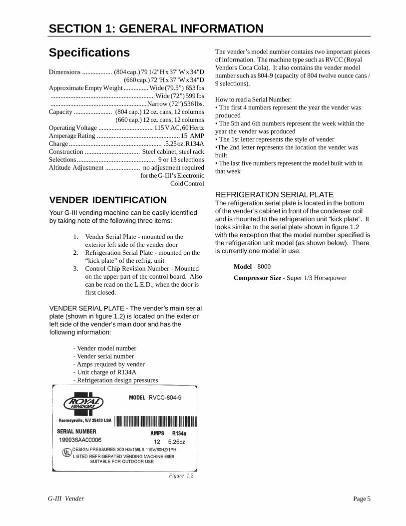
VENDER SERIAL PLATE - The vender’s main serialplate (shown in figure 1.2) is located on the exteriorleft side of the vender’s main door and has thefollowing information:
- Vender model number- Vender serial number- Amps required by vender- Unit charge of R134A- Refrigeration design pressures
The vender’s model number contains two important piecesof information. The machine type such as RVCC (RoyalVendors Coca Cola). It also contains the vender modelnumber such as 804-9 (capacity of 804 twelve ounce cans /9 selections).
How to read a Serial Number:• The first 4 numbers represent the year the vender wasproduced• The 5th and 6th numbers represent the week within theyear the vender was produced• The 1st letter represents the style of vender•The 2nd letter represents the location the vender wasbuilt• The last five numbers represent the model built with inthat week
REFRIGERATION SERIAL PLATEThe refrigeration serial plate is located in the bottomof the vender’s cabinet in front of the condenser coiland is mounted to the refrigeration unit “kick plate”. Itlooks similar to the serial plate shown in figure 1.2with the exception that the model number specified isthe refrigeration unit model (as shown below). Thereis currently one model in use:
Model - 8000
Compressor Size - Super 1/3 Horsepower
Figure 1.2

Four-Button ProgrammingAll programming of the vender options is done in theService Mode. To enter the Service Mode, open the venderdoor and press and release the Service Mode Button whichis located on the controller board (see Figure 2.7).
The first four selection switches are used to navigatethrough the service routines as follows:
Button Meaning Usage
1 (ABORT) Escape, Cancel 2 (UP) Increase, Next 3 (DOWN) Decrease, Previous 4 (ENTER) OK, Accept, Save
The controller will automatically return to the Closed-DoorMode if:
1) No response from the selection switches is receivedwithin approximately five minutes;
2) The Service Mode Button is pressed a second time;3) The “rtn” function is activated.
If the door is closed, the controller will return to the SalesMode. If credit exists, the credit amount will be displayedafter returning to the Sales Mode.
SECTION 2: SET-UP AND INSTALLATION
Figure 2.7
1 2 3 4 5 6 7 8 9 10 11 12 13 14 15 16
1 2 3 4 5 6
REDWHITEKEYBLACK
1 2 3 4 5 6 7 8 9 10 11 12 13
KEY
KEY
KEY
KEY
1 2 3 4 5 6 7 8
ZX1ZX5ZX3ZX4
ZX6KEY
1 2 3 4 5 6 7 8 9 10 11 12 13
WHITEBLACKREDGREENKEYGRAYPINKORANGEVIOLET
10 9 8 7 6 5 4 3 2 1
BLACKBROWN
REDKEY
BLACKKEY
RED
BROWN
8 7 6 5 4 3 2 1YELLOWGREEN
BROWNRED
18 17 16 15 14 13 12 11 10 9 8 7 6 5 4 3 2 1GREY
BLACKKEYRED
6 5 4 3 2 1GRNDRED
BLACK
WHT/GRNWHT/BLU
PINK
WHT/ORG
WHITEYELLOWORANGE
GREEN
PURPLE
BLUEBROWN
18 17 16 15 14 13 12 11 10 9 8 7 6 5 4 3 2 1
CO
L 1
18 17 16 15 14 13 12 11 10 9 8 7 6 5 4 3 2 1
CO
L 2C
OL 3
CO
L 4K
EY
CO
L 5C
OL 6
CO
L 7C
OL 8
CO
L 9C
OL 10
CO
L 11C
OL 12
4 3 2 1BLA
CK
RE
D
NE
UT
RA
L
24 vA
C
P5
5 vD
C
NEUTRAL
5 vD
C
5 vDC
P3
P11
5 vD
C
5 vD
CP2
P1
NE
UT
RA
L
NE
UT
RA
L5 vD
C
P8
P7
5 vD
C24vD
C24vD
C24 vD
C
P6
P10
6 53
42 1
24 vA
C
P4A
P4
P9
READY TO VEND INDICATORS
LED
1 R150
J17
P15
9 8 7 6 5 4 3 2 1
PURPLEBROWN
ORANGE
GREENBLUERED
YELLOW
P16
KEY
BLACK
5 vD
C
5 vD
C
NE
UT
RA
L
CONTROLLER
S1
BLA
CK
RE
DG
RE
EN
WH
ITE
BR
OW
NB
LUE
Dex PhoneJack
Mode Switch& HHCInterface
L.E.D.Display
ChuteSensor
SelectionSwitches
Sold-Out IndicatorsMDB Power
Vend Motor/Encoder
RelayOutputs
Options
Home Sensor/Door Switch
TemperatureSensor

SEC
TIO
N 2
: SET
-UP
AN
D IN
STA
LLAT
ION
EXTERNAL MENU
Eror
CASH
SALE
rtn
INTERNAL (SERVICE) MENU
Eror
CPO
tuFL
tESt VEnd SL SO dSP rELY
Sel. Switch Test (1-13)
LED Segments, Correct Change Lamp& Sold Out Lamp Flash Test
CO1 - CO12
S/O Test (1-12)
Cnp
Fan
Lit
Htr
PASSWORD PROTECTED MENU
CASH
SALE
PrIC
StS
Con
CCOC
PrEU
OPt1 - OPt9 CLr CStS rStS
C1 C2 C3 C4 C5 C6 C7 C8 C9 C10
Con CCU ACC
LAnG
tinE
Lit
rFrG
EnG Frn GEr Ita Port ESP SLO
Enb YEAR nth dAtE Hour dSt
NA
OFF
EU
AUS
Enb Strt StoP SEtPdeG Stor dSP
dAy
Hour
dAy
Hour
If Configuration 2 is enabled,the following menus will appear:
bLC1
bLC2
dISC
OVEr
SdEP
rUnd
Enb Strt StoP
dAy
Hour
dAy
Hour
SEL Lit
Enb Strt StoP
dAy
Hour
dAy
Hour
SEL Lit
Enb Strt StoP
dAy
Hour
dAy
Hour
SEL LESS
FrE bLC dSC Lit FrG
1 - 13 ALL
Set by selection
PASS
rtn
K.O.Programming
Flowchart
Strt StoP
dAy
Hour
dAy
Hour
SEL rAtE
Enb Strt StoP
dAy
Hour
dAy
Hour
R
6/01Rev. A

G-III VenderPage 8
SECTION 2: SET-UP AND INSTALLATION
Code LevelsIndividual modes are identified by displaying their code asfollows:
CODE DESCRIPTION
Eror Error Display ModeCPO Coin Payout ModetUFL Tube Fill ModetESt Test Vend ModePASS Password Protection• CASH Cash Counter Display Mode• SALE Vend Counter Display Mode• PrIC Selection Price Setting Mode• StS Space to Sales Programming Mode• Con Machine Configuration Mode (C1-C10)• CCOC Correct Change Only• PrEU Preview Data Password Mode• LAnG Language Selection Mode• tinE Time/Date Setting Mode• rFrG Refrigeration Control Mode• bLC1* Block Selection Mode• bLC2* Block Selection Mode• dISC* Discount Setting Mode• OVEr* Manual Switch Over-ride Mode• SdEP* By-selection Setting Mode• rUnd* Remote Vend Mechanism Routinertn Return to Sales Mode
* If optional features (C2 under Con Menu) are dis-abled, these menus will not appear, and will not apply.The exception to this rule is SdEP which will not appear,but will still apply.
• Code level modes preceded with a “•” are consideredsensitive to incorrect setup procedures. Therefore, they canonly be accessed after a predefined and unchangeablepassword has been entered via the selection switches. Oncethe password has been entered, all functions will be available.“PASS” will be displayed only if the password has not beenentered. Otherwise the function codes will be displayed aslisted above.
The password is entered via the first four selection switcheswhile the controller is displaying “PASS.” The password mustbe entered within 10 seconds in the following order: 4-2-3-1.The display will go blank after the first selection switch ispressed. After completing the sequence, press (ENTER). If thepassword is not recognized, the display will remain blank butwill reappear if no buttons are pressed..
Code Level ExplanationERROR DISPLAY MODE
If (ENTER) is pressed at the “Eror” prompt, the controllerwill enter the error display mode. If no errors haveoccurred since the last error reset, the display will show“nonE.” If an error has been detected since the last errorreset, the display will show the first error summary codethat has occurred.EXAMPLE: “CJXX” would indicate a column jamerror.
If (ENTER) is pressed, the controller will display thedetailed error for the summary code. (UP) and (DOWN)will cycle through any remaining error detail codes. If the(ABORT) is pressed while displaying any detailed code,the controller will return to the summary code. If the(ABORT) is pressed while displaying any summarycode, the controller will return to the code level.
If (ENTER) is pressed and held for two seconds duringthe display of a detailed error code, that error will becleared. If other currently accessed detailed errors exist,the next error will now be displayed. If no other errors ofthis type exist, the next error summary code will bedisplayed, or “nonE” if no other errors exist.
Vend Mechanism Error “UEnd”The “UEnd” prompt indicates that at least one vendmechanism error has been detected. If the (ENTER) isactivated, the controller will display:
“CJxx” Indicating a column jam error.“CS” Chute sensor is active for more than 5 mins.“hS” Indicating a home sensor error.“EC” Indicating an encoder error.“rE” Indicating a “rabbit” error.
If more than one detailed error is presented, they may beviewed using (UP) and (DOWN) . These errors arecleared via the HHC or Service Mode.
Control System Error “Ctr1”After the “Ctrl” prompt, the controller will display:dS Indicating a door switch error.Ran Indicating RAM error.ACLO Indicating low AC.SF Indicating a scaling factor error.IS Indicating an inlet sensor error.Ib Indicating the inlet is blocked.

Page 9G-III Vender
SECTION 2: SET-UP AND INSTALLATIONSelection Switch Error “SEL”After the “SEL” prompt, the controller will display“SSXX” where ‘XX’ indicates the selection switch hasbeen active for more than 15 seconds while in the salesmode.
Space to Sales Error “StS”After the “StS” prompt, the controller will display“UAXX” where ‘XX’ represents the column which is notassigned to a selection.
Coin Changer Error “CHAr”After the “CHAr” prompt, the controller will display:
“CC” Indicating a changer communications error.“tS” Indicating a tube sensor error.“IC” Indicating an inlet chute blocked error (no coins
sensed in the acceptor for over 96 hours).“tJXX” Indicating a tube jam error (where ‘XX’
indicates the tube number).“CrCH” Indicating a changer ROM checksum
error.“EE” Indicates excessive escrow.“nJ” Indicating a coin jam.“LA” Indicating a low acceptance rate.
The “CC” error is cleared when proper communication isestablished. The “CSF” error is cleared upon power up orvia the HHC or service mode. The “IC” error is clearedwhen a coin is accepted. All other “CHAr” errors are resetvia the HHC or Service Mode, or when the conditioncausing the error no longer exists.
Bill Acceptor Error “bUAL”After the “bUAL” prompt, the controller will display:
“bC” Indicating a bill communication error.“bFuL” Indicating a full bill stacker.“biLL” Indicating a defective motor.“bJ” Indicating a bill jam error.“brCH” Indicating a bill acceptor ROM
checksum error.“bOPn” Indicating an open cash box.“bS” Indicating a sensor error.
The “bC” error is cleared when proper communication isestablished. The “bSF “ error is cleared upon power up,via the HHC or the service mode. The remaining errorsare cleared whenever the validator reports no errors and isenabled (the validator is “enabled” when it acceptsmoney).
Card Reader Error “Crdr”After the “Crdr” prompt, the controller will display:
“CrC” Indicating a card reader communication error.“Crxy” Indicating an error number reported by the card
reader, where ‘x’ is a hexadecimal digitrepresenting the card reader code and ‘y’ is ahexadecimal digit representing themanufacturer-specific sub-code.
Refrigeration Error “rFrG”After the “rFrG” prompt, the controller will display:
“SEnS” Indicating a temperature sensor error.“CoLD” Indicating temperatures three or more
degrees below the compressor cut-out setting.“Hot” Indicating cabinet temp. is above limit.“CnPr” Indicating that the compressor is not
cooling within 30 minutes of turning on, or;“Htr” indicating the heating system has failed to
increase 1 deg. per hour while heater is on.
The “CoLD” error is cleared when the temperature risesabove three degrees below cutout. The “Hot” error iscleared when the temperature drops to the “SetP”. The“SEnS” error is cleared when a sensor is detected. Theremaining “rFrG” errors can also be cleared via the HHC orservice mode.
External MenuAccess the External Menu by entering your 4-digitpassword (factory set 4-2-3-1), when the main door isclosed.
The External Menu contains:Errors (Eror)Cash Counts (CASH)Sales Counts (SALE)Return (rtn)
Note: Use the Preview Data Password Mode (PrEU)under the password protected menu to display or changethe current password.

G-III VenderPage 10
SECTION 2: SET-UP AND INSTALLATION
Internal (Service) Menu
COIN PAYOUT MODEIf (ENTER) is pressed at the “CPO”
prompt, the controller will enter the coin payout mode anddisplay the lowest coin value that can be paid out. Using(UP) or (DOWN) will allow the operator to cycle throughthe coin values that are routed to the coin tubes. If(ENTER) is pressed, a payout of the displayed value willbe made. Coins will continue to payout as long as(ENTER) is held down. If (ABORT) is pressed at any time,the controller will return to the “CPO” prompt. Press the(UP) button to proceed to the next prompt “tuFL”.
TUBE FILL MODEIf (ENTER) is pressed at the “tuFL”
prompt, the controller will enter the coin tube fill mode. Inthis mode, the operator is allowed to deposit any coin intothe coin changer’s acceptor where that coin tube is notfull. The tube inventory level will be displayed after eachcoin is accepted. If (ABORT) is pressed at any timeduring this operation, the controller will return to the“tuFL” prompt. Press the (UP) button to proceed to thenext prompt “tESt”.NOTE: This is the only method of loading the tubes thatensures exact cash accountability.
TEST VEND MODEIf (ENTER) is pressed at the “tESt”
prompt, the controller will enter the test vend mode.Using (UP) or (DOWN) will allow the operator to togglebetween the following modes:
“VEnd” Column Vend Test“SL” Selection Switch Test“SO” Sold Out Test (per column)“dSP” Display Test“rELY” Relay Test- (CnP, FAn, Lit, Htr)
Column Vend Test “UEnd”If (ENTER) is pressed at the “UEnd” prompt, the control-ler will enter the column vend test mode. The display willshow “CO 1”, which represents “column 1”. Pressing(UP) and (DOWN) cycle through the available columns.If (ENTER) is pressed, the controller will attempt to vend aproduct from the displayed column. Vends made while inthis routine will affect only the test vend counters. If(ABORT) is pressed at anytime during this operation, thecontroller will return to the “UEnd” prompt. Press the(UP) button to proceed to the next prompt “SL”.
Selection Switch Test “SL”If (ENTER) is pressed at the “SL” prompt, the controllerwill enter the selection switch test mode. The display willshow “SL 4”, which indicates that the fourth selectionswitch was pressed last. When any selection switch ispressed, it will be represented by the right two digits. Thelast selection switch pressed will remain on the displayuntil the service mode timer expires or the (ABORT)button is pressed and held for two seconds, this will returnthe controller to the “SL” prompt. Press the (UP) buttonto proceed to the next prompt “SO”.
Sold Out Test “SO”If (ENTER) is pressed at the “SO” prompt, the controllerwill enter the sold out test mode. The display will show“C 1X”, which represents column one, if X is (0) columnone is not sold out and if X is (1) column one is sold out.Pressing (UP) and (DOWN) cycles through the availablecolumns. Pressing the (ENTER) button has no action.Pressing (ABORT) button will return the controller to the“SO” prompt. Press the (UP) button to proceed to thenext prompt “dSP”.
Display Test “dSP”If (ENTER) is pressed at the “dSP” prompt, the controllerwill enter the display test mode. The display, correctchange only light and sold out light will run a diagnostictest until service timer expires or if the (ABORT) button ispressed. Press the (UP) button to proceed to the nextprompt “rELY”.
Relay Test Mode “rELY”If (ENTER) is pressed at the “rELY” prompt, the controllerwill enter the relay test mode by displaying “CnpX.” If(ABORT) is pressed in this mode, the user will return tothe “rELy” prompt. Using (UP) or (DOWN) will allow theoperator to toggle between the following modes:
“CnP” Compressor Relay“FAn” Evaporator Fan Relay“Lit” Light Relay“Htr” Heater Relay
If (ENTER) is pressed at the “CnPX” prompt, the controllerwill enter compressor relay test. If X = (0) the relay is notactivated and if X= (1) the relay is activated. Pressing(ENTER) will toggle the display between “0” and “1.”
For all relaysX= 1 relay is activated;X= 0 relay is not activated.
Pressing (ABORT) at the “rELy” display will bring you outto “tESt”. Press the (UP) button to proceed to the nextprompt “PASS”.

Page 11G-III Vender
SECTION 2: SET-UP AND INSTALLATION
Password Protected MenuPASSWORD PROTECTION“PASS” will be displayed only if the
password has not been entered. Otherwise the functioncodes will be displayed as listed under the Code Levelsection of this manual. The password is entered via thefirst four selection switches while the controller isdisplaying “PASS.” The password must be entered within10 seconds in the following order: 4-2-3-1. The display willgo blank after the first selection switch is pressed. Aftercompleting the sequence, press (ENTER). If the passwordis not recognized, the display will go back to “PASS”.
CASH COUNTERDISPLAY MODE
If (ENTER) is pressed at the “CASH” prompt, the control-ler will enter the non-resettable cash display mode bydisplaying “CASH”/“XXXX”/“XX.XX” where the ‘X’srepresent total cash over machine life. A decimal will bedisplayed in the appropriate position with the lower fourdigits. If the cash amount is less than five digits long, theupper four digits are not displayed. Using (UP) or(DOWN) will cycle through each selection as “CANN”“XXXX/XX.XX,” where the “NN” indicates the selectionand the ‘X’s represent the resettable cash per selection. If(ABORT) is pressed anytime during this operation, thecontroller will return to the code level. Press the (UP)button to proceed to the next prompt “SALE”.
VEND COUNTERDISPLAY MODE
If (ENTER) is pressed at the “SALE” prompt, the controllerwill enter the non-resettable vend display mode bydisplaying “SALE/“XXXX”/“XXXX.” where the ‘X’srepresent the number of all paid vends over machine life. Ifthe sales amount is less than five digits, the upper fourdigits will not be displayed. Using (UP) or (DOWN) willcycle through each selection as “SLNN”/“XXXX/XXXX.”where the “NN” indicates the selection and the ‘X’srepresent the resettable number of vends for that selec-tion. A decimal will be displayed in the right-most positionwith the lower four digits. If (ABORT) is pressed anytimeduring this operation, the controller will return to the“SALE” prompt. Press the (UP) button to proceed to thenext prompt “PrIC”.
SELECTION PRICESETTING MODE
If (ENTER) is pressed at the “PrIC” prompt, the controllerwill enter the selection price setting mode. The display willshow “Pr 1” if the machine is in multi-price mode, or “SPrI”if the machine is in single-price mode.
The G-III Vender is shipped from the factory in multi-pricemode with a .75 cent vend price.
Notes:1. In the single-price mode, the price for selection 1 is the
price for all selections. Single-price is displayed as“SPrI” instead of “Pr1” as a reminder to the operatorthat the machine is currently in single-price mode.
In the multi-price mode, individual selection prices can bechanged using the (UP) and (DOWN) to display “PrXX,”where ‘XX’ is the selection number, or choose “ALL” tochange the prices for all selections. If (ENTER) is pressed,the display will show the current price for the displayedselection. Using (UP) or (DOWN) will increase or decreasethe price. Holding (UP) or (DOWN) for more than fiveseconds will cause the price to change at 10 times thenormal rate. When the desired price is on the display,pressing (ENTER) will save that price, while pressing(ABORT) will return to the selection level without saving.Press the (UP) button to proceed to the next prompt “StS”.
SPACE-TO-SALESPROGRAMMING MODE
If (ENTER) is pressed at the “StS” prompt, the controllerwill enter the space-to-sales programming mode bydisplaying “OPtn,” where ‘n’ is the current optionselected; “CStS” for custom configuration, or “rStS”.Using (UP) or (DOWN) will allow the operator to cyclethrough all 12 available space-to-sales options “OPt1”-“OPt9,” “CLr” as well as the “CStS” and “rStS” options.When one of the “OPt1”-“OPt9”, “CLr” options are on thedisplay, pressing (ENTER) will select that space-to-salesoption and return to the code level. If one of the “OPt1”-“OPt9,” “CLr”, “CStS,” or the “rStS” option is displayedand (ABORT) is pressed, the user will return to the “StS”prompt without changing the settings.
NOTES:1.If (ENTER) is pressed at “CLr”, the “StS” settings willreset to none.2. There is a decal, located on the inner door, that showsthe relationship between columns and selections.3. If the clear program is used without assigning anycolumns, the LED with read “Sold-out”.
G-III VenderPage 12
Recommended Space-to-Sales “rStS”If (ENTER) is pressed at the “rStS” prompt, a recom-mended space-to-sales configuration is calculated, basedon first choice attempts since StS was last changed. Thedisplay will flash “SL 1” and alternate this message witheither “nonE,” indicating that no columns should beassigned to selection 1, or a sequence of numbers thatrepresent columns that should be assigned to selection 1.Pressing (UP) or (DOWN) will cycle through the remain-ing selections. Pressing (ENTER) or (ABORT) will movethe user to the “SAUE” option, where pressing (ENTER)will save the recommended space to sales or pressing(ABORT) will return the “StS” prompt without saving thechanges. Press the (UP) button to proceed to the nextprompt “Con”.
MACHINE (C1-C10)CONFIGURATION MODE
If (ENTER) is pressed at the “Con” prompt, the controllerwill enter the machine configuration mode by displaying“C1-1,” which designates configuration option number 1.If (ABORT) is pressed while at the “Cn” level, thecontroller will return to the code level. Pressing (UP) or(DOWN) will allow the selection of available configurationoptions. Pressing (ENTER) will change the display to “CnX” where “n” is the configuration number and “X” is thecurrent status of the option. The status is changed using(UP) or (DOWN). Pressing (ENTER) saves the status ofthe current option and returns the user to the “Cn”prompt, while pressing (ABORT) returns to the “Cn”prompt without saving. From the “Con” prompt, press(UP) to proceed to the next prompt “CCOC”.
Royal Vendors recommended E.V.S. configurationsettings:Con 1 - (1) Multi priceCon 2 - (1) Opt features onCon 3 - (0) Greeting displayedCon 4 - (0) Totals disabledCon 5 - (0) Mis resetCon 7 - (0) Five minute timer usedCon 8 - (1) Force attempt enabledCon 9 - (0) Multi purchase disabledCon 10 - (0) Bill escrow
Single/Multi-PriceThis configuration chooses between the
single-price and multi-price settings by pressing (UP) or(DOWN). In the single-price mode, the price of selection(0) will be used for all selections. In the multi-price mode(1), each selection can be set to a different price.
If X = 1, Multi-pricing is used.If X = 0, Single-pricing is used.
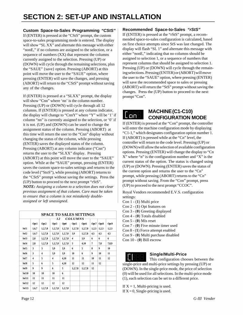
SECTION 2: SET-UP AND INSTALLATIONCustom Space-to-Sales Programming “CStS”If (ENTER) is pressed at the “CStS” prompt, the customspace-to-sales programming mode is entered. The displaywill show “SL XX” and alternate this message with either“nonE,” if no columns are assigned to the selection, or asequence of numbers (XX) that represent the columnscurrently assigned to the selection. Pressing (UP) or(DOWN) will cycle through the remaining selections, plusthe “SAUE” {save} option. Pressing (ABORT) at thispoint will move the user to the “SAUE” option, wherepressing (ENTER) will save the changes, and pressing(ABORT) will return to the “CStS” prompt without savingany of the changes.
If (ENTER) is pressed at a “SLXX” prompt, the displaywill show “Cnn” where ‘nn’ is the column number.Pressing (UP) or (DOWN) will cycle through all 12columns. If (ENTER) is pressed at any column indicator,the display will change to “CnnY” where “Y” will be ‘1’ ifcolumn “nn” is currently assigned to the selection, or ‘0’ ifit is not. (UP) and (DOWN) can be used to change theassignment status of the column. Pressing (ABORT) atthis time will return the user to the “Cnn” display withoutchanging the status of the column, while pressing(ENTER) saves the displayed status of the column.Pressing (ABORT) at any column indicator (“Cnn”)returns the user to the “SLXX” display. Pressing(ABORT) at this point will move the user to the “SAUE”option. While at the “SAUE” prompt, pressing (ENTER)saves the custom space-to-sales settings and returns to thecode level (“StoS”), while pressing (ABORT) returns tothe “CStS” prompt without saving the settings. Press the(UP) button to proceed to the next prompt “rStS”.NOTE: Assigning a column to a selection does not clearprevious assignment of that column. Care must be takento ensure that a column is not mistakenly double-assigned or left unassigned.
Opt 1 Opt 2 Opt 3 Opt4 Opt 5 Opt 6 Opt 7 Opt 8 Opt 9
Sel 1 1,6,7 1,2,7,8 1,2,7,8 1,2,7,8 1,2,7,8 1,2,7,8 1,2,3 1,2,3 1,2,3
Sel 2 1,6.7 1,2,7,8 1,2,7,8 1,2,7,8 3,9 1,2,7,8 4,5 4,5 4,5
Sel 3 2,8 1,2,7,8 1,2,7,8 1,2,7,8 4 3,9 6 6 6
Sel 4 2,8 1,2,7,8 1,2,7,8 1,2,7,8 5 4,10 7 7,8 7,8,9
Sel 5 3 3 3,9 3,9 6 5 8 9 10
Sel 6 3 4 3,9 3,9 10 6 9 10 11
Sel 7 4 5 4 4,10 11 11 10 11 12
Sel 8 5 6 5 4,10 12 12 11 12
Sel 9 9 9 6 5 1,2,7,8 1,2,7,8 12
Sel 10 10 10 10 6
Sel 11 11 11 11 11
Sel 12 12 12 12 12
Sel 13 1,6,7 1,2,7,8 1,2,7,8 1,2,7,8
SPACE TO SALES SETTINGS12 COLUMNS
Page 13G-III Vender
SECTION 2: SET-UP AND INSTALLATIONOptional Features EnableThis configuration enables optional
features “bLC1”, bLC2”, “dISC”, “OUEr” and “SdEP” if setto “1”.
If set to “0” the optional features will be disabled and willnot be displayed in the menus. Notes: The timers and thekey switch functions will not work if set to “0”. SdEP isthe only optional feature that will work if set to “0”
P.O.S. DisableThis option is used to disable the point
of Sales (P.O.S.) message if set to “1”.
If set to “0” the P.O.S. is enabled (greeting will bedisplayed).
Open Door TotalsThis option changes the Open-Door
Mode Display (see “Modes of Operation” section of thismanual for a description of the Open-Door Mode). Ifenabled, the total machine sales and total machine cashvalues are displayed before the error codes. These valuesrepresent the number of all paid vends and the cashamount of all paid vends, respectively. The sales and cashvalues are displayed the same as in the “SALE” and“CASH” service mode functions. The display shows“SALE”/ “XXXX”/ “XXXX.” for two seconds each fourdigits, then “CASH”/ “XXXX”/ “XX.XX”, then existingerrors or “nonE.” If this option is disabled, existing errorsare displayed, or “nonE” if no errors exist.
If X = 1, “SALE”/ “XXXX”/ “XXXX.”,“CASH”/ “XXXX”/ “XX.XX”,and existing errors or “nonE” are displayed.
If X = 0, Existing errors or “nonE” is displayed.
Door Switch ResetThis option is used to allow the door
switch to reset all resettable MIS.
If X = 1, All resettable MIS registers are reset when thedoor switch is activated, if any one of theresettable MIS registers are read.
If X = 0, All resettable MIS registers will be reset onlywhen the “CF” command is received from theHHC.
For Future Use
Save CreditThis configuration is used to determine
how long the credit is displayed.
If X = 1, The credit is left on the display indefinitely.If X = 0, After 5 minutes the credit is erased.
Escrow Rule #1:Forced Attempt
This configuration prevents the machine from becoming achange maker. When this mode is set to (1) enabled,escrow of coins is allowed until any of the following:• Any bill is inserted into the bill acceptor.• Any “cash box” coin (a coin that is not assigned to a
tube) is inserted.• The maximum vend price is reached. Once any of these
conditions are met, escrow is ignored and a vend mustbe made.
If a selection is made that is sold out or locked out, thisoption will override and an escrow will be honored.
If this mode is set to (0), the force-attempt option will bedisabled.NOTE: Force attempt has no effect on the card reader.Once a card is inserted, it can always be returned to thecustomer via an escrow or the return switch on the cardreader.
If X = 1, Force-attempt is enabled.If X = 0, Force-attempt is disabled.
Escrow rule #2:Multi-Purchase
Allows multiple purchases without reentering coins. Ifenabled, instead of returning the change after a vend, thecredit will remain on the display to be used for anotherselection. An escrow will be honored at any time. Thisoption will take precedence over the force-attempt optionafter the first vend has been completed.
If X = 1, Multi-purchase is enabled.If X = 0, Multi-purchase is disabled.
NOTE: If the card reader is not multi-vend capable, thecard will be ejected after each vend regardless of thestate of this option.
Bill Escrow InhibitThis configuration allows the escrow of
bills. If ‘X’ is set to “1” and the bill value inserted takesthe accumulated credit over the maximum vend price, billswill always go to the cash box. If the rule is set to “0”, thebill will be held in the escrow position.
If X = 1, Bill escrow is disabledIf X = 0, Bill escrow is enabled.

G-III VenderPage 14
LANGUAGESELECTION MODE
The “LAng” mode gives you the opportunity to setvending messages in any of the following internationallanguages:
English - “EnG”French - “Frn”German - “GEr”Italian - “ItA”Portuguese - “Port”Spanish - “ESP”Slovenian - “SLO”
Pressing (ENTER) will display the last programmedsetting. Press (UP) or (DOWN) to cycle through theavailable languages. When desired language is displayed,press the (ENTER) button to save your choice. If(ABORT) is pressed anytime during this operation, thecontroller will return to the “LANG” prompt. Press the(UP) button to proceed to the next prompt “tinE”.
TIME/DATESETTING MODE
If (ENTER) is pressed at the “tinE” (time) prompt, thecontroller will enter the time setting mode and the firstdisplay will be “Enb” (enable). Using (UP) or (DOWN) willallow you to cycle through all available time selectionoptions. Pressing (ENTER) will allow you to set the sub-menu you have entered into (example “Enb”). If (ABORT)is pressed anytime during this operation, the controller willreturn to the “tinE” prompt. Press the (UP) button toproceed to the next prompt “Lit”.
TIME SELECTION OPTIONS(current time settings)
*“Enb” Enable (must be set to “1” )“yEAr” Current Year (Example ‘99)“nth” Current Month“dAtE” Current Day of the Month“Hour” Current Time (hours, minutes)“dSt “ Daylight Savings Time Selection
(NA, OFF, AUS, EU)
*NOTE: Enable must be set to “1” at all times to assureproper vender operations.
Enable Setting “Enb”This setting controls the time and date support by keepinga continuous updated clock connection (1) or you canturn the clock off (0), so the clock is not updated. Togglebetween the (1) and (0) by pressing (UP) or (DOWN).Pressing (ENTER) will save the current setting and returnto the “Enb” prompt. Press the (UP) button to procede tothe next prompt “YEAr”.
If X=1, Will keep the clock current when enabled.If X=0, Will not keep the clock current if disabled.
SECTION 2: SET-UP AND INSTALLATION
CORRECT CHANGE ONLYCONTROL MODE
If (ENTER) is pressed at the “CCOC” prompt, the control-ler will enter the correct change only control mode.The first sub-menu “Con”, if disabled (0), it wouldprevent customers from being cheated if sufficient changeis not available for payout. The vend is aborted and creditis returned.
If X=1, No cheat rule is enabled;(The vender will payback available change,however the customer could potentially becheated).
If X=0, Will not cheat the customer if disabled.
NOTE: If “Con” is set to “0”, CCU and ACC donot apply:The second sub- menu “CCU”, will control the ExactChange Only light. If the vender can not make change forthe value (or lower), the Exact Change Only lamp willlight when set to “00.00”. The four digit value can rangefrom “00.00 to 99.95” which represents the correctchange value. Using the (UP) or (DOWN) buttons willincrease or decrease the number in increments of thelowest coin tube amount.
The third sub-menu “ACC” (unconditional acceptance ofcurrency), controls the value for dollar coins or bills to beaccepted, regardless. Upon entering “ACC” the promptwill show the current four digit value (00.00 - 99.95)which represents the unconditional acceptance value.Using the (UP) or (DOWN) buttons will increase ordecrease the number in increments of the lowest coin tubeamount. If (ABORT) is pressed anytime during thisoperation, the controller will return to the code level.Pressing the (UP) button will procede to the next prompt“PrEU”.
PREVIEW DATA “External”PASSWORD MODE
If (ENTER) is pressed at the “PrEU” prompt, the controllerwill display the current password for the external previewmode. The first digit of the number will be flashing.Pressing (UP) or (DOWN) will adjust the currently flashingdigit up or down. Pressing (ENTER) will save the currentlyflashing digit and the next digit of the password will beginflashing. All digits may be modified in this manner.Pressing (ENTER) while the last digit is flashing saves thecurrently displayed password and returns to the “PrEU”prompt, while pressing (ABORT) at any time in theprocedure returns to the “PrEU” prompt without saving.From the “PrEU” prompt pressing (UP) will procede to thenext prompt “LAnG” Note: Password digits correspondto selection switches. If a digit is set to a nonexistingselection switch number or “0”, it will not be possible toenter the preview mode.

Page 15G-III Vender
SECTION 2: SET-UP AND INSTALLATION
Set Year “YEAr”If (ENTER) is pressed at the “yEAr” prompt, the last twodigits of the year are displayed and will be flashing.Pressing (UP) or (DOWN) will increase or decrease theyear setting. Pressing (ENTER) will save the displayedyear setting and return the user to “yEAr” while pressing(ABORT) will return to “yEAr” without saving. Press the(UP) button to proceed to the next prompt “nth”.
Set Month “nth”After (ENTER) is pressed at the “nth” prompt, you will beable to select the current month (01-12). Pressing (UP) or(DOWN) will increase or decrease the month setting.Pressing (ENTER) will save the displayed month andreturn the user to the month level. Pressing (ABORT)while the month digits are flashing returns to the monthlevel without saving the month. Press the (UP) button toproceed to the next prompt “dAtE”.
Set Date “dAtE”If (ENTER) is pressed at the “dAtE” prompt, two digitswill appear and represent the day of the month (01-31).Pressing (UP) or (DOWN) will increase or decrease thenumber. Pressing (ENTER) will save the displayednumber and return the user to the date level. Pressing(ABORT) while the numbers are flashing returns to thedate level without saving the number. Press the (UP)button to proceed to the next prompt “Hour”.
Set Hour “Hour”If (ENTER) is pressed at the “Hour” prompt, the currenttime is displayed in a 24-hour format. The left two digitsof the display show the current hour, the right two digitsshow the current minutes. While the hour setting isflashing, pressing (UP) or (DOWN) will increase ordecrease the hour setting. If (ENTER) is pressed, theminute setting will flash. (UP) or (DOWN) will set theminutes. Pressing (ENTER) at this point will save thedisplayed hour and minutes setting and return the user to“hour.” Pressing (ABORT) while the hour or minutesdigits are flashing returns to “Hour” without saving thehour or minutes. Press the (UP) button will procede to thenext prompt “dSt”
Daylight Savings Time “dSt”After the (ENTER) button is pressed at the “dSt” prompt,the display will show the current daylight saving timecode. Using the (UP) and (DOWN) buttons will rotatethrough the available options. Pressing (ENTER) any timewill save the selected options and return the user to “dSt.”Pressing (ABORT) button while in (NA, OFF, AUS, or EU)will return you to the “dSt” without saving any changes.
LIGHTING CONTROL MODE(Optional Relay Kit Required)If (ENTER) is pressed at the “Lit” prompt, the controllerwill enter the lighting control mode and the first displaywill be “Enb”(enable). Using (UP) or (DOWN) will allowyou to cycle through all available lighting control modeoptions (Enb, Strt, Stop).
Enable “Enb”If (ENTER) is pressed at the “Enb” prompt, the controllerwill enter the lighting control enable mode. If set to (1) thelighting control will be enabled and the lighting panels ofthe vender will be turned off during the following pro-grammed time blocks (if the lamp relay kit is installed).If set to (0) the lighting control will be disabled. Togglebetween the (1) and (0) by pressing (UP) or (DOWN).Pressing (ENTER) will save the current setting. If(ABORT) is pressed anytime during this operation, thecontroller will return to the “Lit” without saving yoursettings. Pressing (UP) will procede to the next prompt“Strt”.
If X=1, The lighting control is (on) enabled.If X=0, The lighting control is (off) disabled.
Start Time Setting “Strt”If (ENTER) is pressed at the “Strt” prompt, the controllerwill display “daY”(day of the week). Enter into “daY” bypressing the (ENTER) button. The display will show thecurrent day of the week followed by a (1) if the timer isactive on that day or (0) if the timer is not active on thatday.
If X= 1 The timer is active on that day.If X= 0 The timer is not active on that day.
Using (UP) or (DOWN) will allow you to cycle through thedays of the week (non, tue, UEd, thu, Fri, SAt, Sun or All).
NA North American RulesOFF No daylight savings time changes madeAUS Australian RulesEU European Rules
Pressing the (ABORT) button at the “dSt” display, thecontroller will return to the “tinE” prompt. Press the (UP)button to proceed to the next prompt “Lit”.

G-III VenderPage 16
Stop Time Setting “StoP”If (ENTER) is pressed at the “StoP” prompt, the controllerwill display “daY”(day of the week). Enter into “daY” bypressing the (ENTER) button. The display will show thecurrent day of the week followed by a (1) if the timer isactive on that day or (0) if the day is not active on thatday.
If X= 1 The timer is active on that day.If X= 0 The timer is not active on that day.
Using (UP) or (DOWN) will allow you to cycle through thedays of the week (non, tue, UEd, thu, Fri, SAt, Sun or All).Press (ENTER) at the desired day to activate or deactivatethe timer for that day. The value must be blinking to editthe selection. Press (UP) or (DOWN) to toggle between(0) or (1). When desired selection is shown, press(ENTER) to save your selection. If (ABORT) is pressedanytime during this operation, the controller will return tothe “daY” prompt without saving your selection. Pressthe (UP) button to proceed to the next prompt “Hour”.
If (ENTER) is pressed at the “Hour” prompt, the left twodigits of the display will begin to flash, prompting the userto adjust the hour setting. (UP) or (DOWN) is used toadjust the hour. When the desired hour is shown,pressing (ENTER) will cause the right two digits to flash,showing the current minute setting. The minutes are set inthe same fashion. When the minutes are properlydisplayed, pressing (ENTER) will save the stop time andreturn to the “StoP” prompt. Pressing (ABORT) at “StoP”prompt will bring you out to “Lit” prompt. Press the (UP)button to proceed to the next prompt “rFrG”.
SECTION 2: SET-UP AND INSTALLATION
Press (ENTER) at the desired day to activate or notactivate the timer for that day. The value must be blinkingto edit the setting. Press (UP) or (DOWN) to togglebetween (0) or (1). When desired selection is shown,press (ENTER) to save your setting. If the (ABORT) ispressed anytime during this operation, the controller willreturn to the “daY” prompt without saving your selection.Press the (UP) button to proceed to the next prompt“Hour”.
If (ENTER) is pressed at the “Hour” prompt, the left twodigits of the display will begin to flash, prompting the userto adjust the hour setting. (UP) or (DOWN) is used toadjust the hour. When the desired hour is shown,pressing (ENTER) will cause the right two digits to flash,showing the current minute setting. The minutes are set inthe same fashion. When the minutes are properlydisplayed, pressing (ENTER) will save the start time andreturn to the “Hour” prompt, pressing (ABORT) from the“Hour” prompt will return the controller to “Strt” prompt.Press the (UP) button to procede to the next prompt“StoP”. Note: The time is based on 24 hour time (Military time)
REFRIGERATION CONTROLMODE
If (ENTER) is pressed at the “rFrG” prompt, the controllerwill enter the refrigeration control mode by displaying“Enb”, indicating the energy conservation mode. Using(UP) or (DOWN) will allow the operator to toggle betweenthe following modes:
“Enb” Enable energy conservation“Strt” Start time setting“Stop” Stop time setting“deG” Degree - Fahrenheit or Celsius“SEtP” Set point (maintaining cabinet temperature
setting)“Stor” Storage - maximum cabinet temperature setting“dSP” P.O.S. temperature display
If (ABORT) is pressed at this point, the controller willreturn to the “rFrG” prompt without saving the changes.Note: The refrigeration unit can not be disabled from thecontroller when using manual thermostat (cold control).
Enable Energy Conservation “EnB”If (ENTER) is pressed at the “Enb” prompt, the controllerwill enter the energy conservation enable mode. If set to(1) the energy conservation control will be enabled andthe cabinet temperature will be allowed to raise to the“Stor” programmed time blocks. If set to (0) the energyconservation will be disabled and the refrigeration unit willoperate as normal and will maintain the “SEtP” tempera-ture. Toggle between the (1) and (0) by pressing (UP) or(DOWN). Pressing (ENTER) will save the current setting.If (ABORT) is pressed anytime during this operation, thecontroller will return to the “Enb” level without savingyour selection. Press the (UP) button to proceed to thenext prompt “Strt”.
If X=1, Enabled (on), the refrigeration unit runs when thestorage temperature is reached*. see note below.
If X=0, The refrigeration unit will run according to the“SEtP” setting.*Note: If enabed (set to 1), the cabinet temperature willrise to the “Stor” temperature operated by the timerprogram, ONLY if the Start and Stop times are set.
Start Time Setting “Strt”If (ENTER) is pressed at the “Strt” prompt, the controllerwill display “daY”(day of the week). Enter into “daY” bypressing the (ENTER) button. The display will show thecurrent day of the week followed by a (1) if the timer isactive on that day or (0) if the timer is not active on thatday.If X= 1 The timer is active on that day.If X= 0 the timer is not active on that day.

Page 17G-III Vender
SECTION 2: SET-UP AND INSTALLATIONUsing (UP) or (DOWN) will allow you to cycle through thedays of the week (non, tue, UEd, thu, Fri, SAt, Sun or All).Press (ENTER) at the desired day to activate or deactivatethe timer for that day. The value must be blinking to editthe setting. Press (UP) or (DOWN) to toggle between (0)or (1). When desired setting is shown, press (ENTER) tosave your setting. If (ABORT) is pressed anytime duringthis operation, the controller will return to the “daY”prompt without saving your selection. Press the (UP)button to proceed to the next prompt “Hour”. If (ENTER) is pressed at the “Hour” prompt, the left twodigits of the display will begin to flash, prompting the userto adjust the hour setting. (UP) or (DOWN) is used toadjust the hour. When the desired hour is shown, pressing(ENTER) will cause the right two digits to flash, showingthe current minute setting. The minutes are set in the samefashion. When the minutes are properly displayed,pressing (ENTER) will save the start time and return tothe “Hour” prompt. Pressing (ABORT) from the “Hour”prompt will return the controller to “Strt” prompt. Press the(UP) button to proceed to the next prompt “StoP”.Note: The time is based on 24 hour time (Military time)
Stop Time Setting “StoP”If (ENTER) is pressed at the “StoP” prompt, the controllerwill display “daY”(day of the week). Enter into “daY” bypressing the (ENTER) button. The display will show thecurrent day of the week followed by a (1) if the timer isactive on that day or (0) if the timer is not active on thatday.
If X= 1 The timer is active on that day.If X= 0 The timer is not active on that day.
Using (UP) or (DOWN) will allow you to cycle throughthe days of the week (non, tue, UEd, thu, Fri, SAt, Sun orAll). Press (ENTER) at the desired day to activate ordeactivate the timer for that day. The value must beblinking to edit the selection. Press (UP) or (DOWN) totoggle between (0) or (1). When desired setting is shown,press (ENTER) to save your setting. If (ABORT) ispressed anytime during this operation, the controller willreturn to the “daY” prompt without saving your setting.Press the (UP) button to proceed to the next prompt“Hour”.
If (ENTER) is pressed at the “Hour” prompt, the left twodigits of the display will begin to flash, prompting the userto adjust the hour setting. (UP) or (DOWN) is used toadjust the hour. When the desired hour is shown, pressing(ENTER) will cause the right two digits to flash, showingthe current minute setting. The minutes are set in the samefashion. When the minutes are properly displayed,pressing (ENTER) will save the stop time. Press the(ABORT) button to return to the “StoP” prompt. Pressthe (UP) button to proceed to the next prompt “dEG”.Note: The time is based on 24 hour time (Military time).
Fahrenheit/Celsius Setting “dEG”If (ENTER) is pressed at the “dEG” prompt, the controllerwill display “dEGX,” if ‘X’ is ‘F’ the controller is currentlyin °F Fahrenheit mode, or if ‘X’ is ‘C’ the controller is inthe °C Celsius mode. Pressing (UP) or (DOWN) will togglethe ‘X’ digit between ‘F’ and ‘C’. Pressing (ENTER) willsave the displayed temperature mode and return the userto the “dEG” prompt, while pressing (ABORT) will returnto the “dEG” prompt without saving any changes. Pressthe (UP) button to proceed to the next prompt “SEtP”.This function can also be accessed via the HHC.
FACTORY SETTING:Fahrenheit: 35°F Set point, 60°F StorageCelsius: 1.5°C Set point, 15.5°C Storage
Set Point Setting “SEtP”The set point setting is what temperature the cabinet willmaintain and when (ENTER) is pressed at the “SEtP”prompt, the controller will display “tt.tX,” where ‘tt.t’ willbe in degrees and X will represent either ‘F’ Fahrenheit or‘C’ Celsius. Pressing (UP) or (DOWN) will increase ordecrease by 1° F (or 0.5°C). Pressing (ENTER) will savethe set point and return the user to the “SEtP” prompt,while pressing (ABORT) will return to the “SEtP” promptwithout saving any changes. Press the (UP) button toproceed to the next prompt “Stor”.
Storage Setting “Stor” (Applies only when usingtimer)The storage setting is the maximum temperature you wantthe cabinet to reach when the timer mode is in use.
If (ENTER) is pressed at the “Stor” prompt, the controllerwill display the current storage setting “tt.tX,” where ‘tt.t’will be in degrees and X will represent either ‘F’ Fahrenheitor ‘C’ Celsius. Pressing (UP) or (DOWN) will increase ordecrease by 1° F (or 0.5°C). Pressing (ENTER) will savethe setting and return the user to the “Stor” prompt, whilepressing (ABORT) will return to the “Stor” prompt withoutsaving any changes. Press the (UP) button to proceed tothe next prompt “dSP”.
POS Temperature Display “dSP”If (ENTER) is pressed at the “dSP” prompt, the controllerwill display “dSPX,” if ‘X’ is ‘0’ the controller is notdisplaying the cabinet temperature in the POS message, or‘1’ if the controller is currently displaying the cabinettemperature after teh POS message. Pressing (UP) or(DOWN) will toggle the ‘X’ digit between ‘0’ and ‘1’.Pressing (ENTER) will save teh currently displayed settingand return the user to the “dSP” prompt, while pressing(ABORT) will return to the “dSP” prompt without savingthe changes. Pressing (ABORT) at the ‘dSP’ prompt willbring you out to “rFrG” prompt. Press the (UP) button toproceed to next prompt “bLC1”, (if Con. 2 is set to “1”).

G-III VenderPage 18
Configuration 2 must be enabled(set to 1) for the following timerfunctions to operate:Note: The timers or the override switch will notfunction, if C2 is set to “0”.
BLOCK SELECTION 1
BLOCK SELECTION 2If (ENTER) is pressed at the “bLC1” or “bLC2” prompt,the controller will enter the block selection control and thefirst display will be “Enb”(enable). Using (UP) or(DOWN) will allow you to cycle through available submenus. If (ABORT) is pressed anytime during thisoperation, the controller will return to the “bLC1” “bLC2”without saving your selection.
Enable Blocking “Enb”If (ENTER) is pressed at the “EnbX” prompt, the control-ler will enter the blocking enable mode. If set to (1) theblocking control will be enabled and the active selectionswill not be able to vend during the following programmedtime blocks. If set to (0) the blocking control will bedisabled. Toggle between the (1) and (0) by pressing(UP) or (DOWN). Pressing (ENTER) will save thecurrent setting. If (ABORT) is pressed anytime duringthis operation, the controller will return to “EnbX”without saving your selection. Press the (UP) button toproceed to the next prompt “Strt” prompt.
If X=1, The blocking control is enabled.If X=0, The blocking control is disabled.
Start Time Setting “Strt”If (ENTER) is pressed at the “Strt” prompt, the controllerwill display “daY”. Enter into “daY” by pressing the(ENTER) button. The display will show the current dayof the week followed by a (1) if the timer is active on thatday or (0) if the day is not active on that day.
If X= 1 The timer is active on that day.If X= 0 The timer is not active on that day.
Using (UP) or (DOWN) will allow you to cycle throughthe days of the week (non, tue, UEd, thu, Fri, SAt, Sun orAll) Press (ENTER) at the desired day to activate ordeactivate the timer for that day. The value must beblinking to edit the selection. Press (UP) or (DOWN) totoggle between (1) or (0). When desired setting is shown,press (ENTER) to save your setting. If (ABORT) is
SECTION 2: SET-UP AND INSTALLATIONpressed anytime during this operation, the controller willreturn to the “daY” prompt without saving your setting.Press the (UP) button to proceed to the next prompt“Hour”. If (ENTER) is pressed at the “Hour” prompt, the left twodigits of the display will begin to flash, prompting the userto adjust the hour setting. (UP) or (DOWN) is used toadjust the hour. When the desired hour is shown, pressing(ENTER) will cause the right two digits to flash, showingthe current minute setting. The minutes are set in the samefashion. When the minutes are properly displayed,pressing (ENTER) will save the start time and return tothe “Hour” prompt. Press the (ABORT) button to returnto the “Strt” prompt. Press the (UP) button to proceed tothe next prompt “StoP”.Note: The time is based on 24 hour time (Military time)
Stop Time Setting “Stop”If (ENTER) is pressed at the “StoP” prompt, the controllerwill display “daY”. Enter into “daY” by pressing the(ENTER) button. The display will show the current dayof the week followed by a (1) if the timer is active on thatday or (0) if the day is not active on that day.
If X= 1 The timer is active on that day.If X= 0 The timer is not active on that day.
Using (UP) or (DOWN) will allow you to cycle throughthe days of the week (non, tue, UEd, thu, Fri, SAt, Sun orAll). Press (ENTER) at the desired day to activate ordeactivate the timer for that day. The value must beblinking to edit the selection. Press (UP) or (DOWN) totoggle between (0) or (1). When desired setting is shown,press (ENTER) to save your setting. If (ABORT) ispressed anytime during this operation, the controller willreturn to the “daY” prompt without saving your selection.Press the (UP) button to proceed to the next prompt“Hour”.
If (ENTER) is pressed at the “Hour” prompt, the left twodigits of the display will begin to flash, prompting the userto adjust the hour setting. (UP) or (DOWN) is used toadjust the hour. When the desired hour is shown, pressing(ENTER) will cause the right two digits to flash, showingthe current minute setting. The minutes are set in the samefashion. When the minutes are properly displayed,pressing (ENTER) will save the stop time. Press the(ABORT) button to return to the “StoP” prompt. Press the
Page 19G-III Vender
SECTION 2: SET-UP AND INSTALLATION
(UP) button to proceed to the next prompt “SEL”.Note: The time is based on 24 hour time (Military time).Selection Setting (SEL)If (ENTER) is pressed at the “SEL” prompt, the controllerwill enter the selection setting and the first display willshow the current setting for selection one “01 X”. If X is(1) the selection is active or (0) the selection is not active.Using (UP) or (DOWN) will allow you to rotate throughthe valid selections or select “ALL”. If (ABORT) ispressed anytime during this operation, the controller willreturn to the “SEL” without saving your selection.
X= (1) The selection is active.X= (0) The selection is not active.
To edit a selection, press (ENTER) when the desiredselection is displayed, the value must blink before anychanges can be made. Pressing (UP) or (DOWN) willchange the current setting. Pressing (ABORT) whileediting a selection will bring you back to the originalsetting without saving any changes. Press the (UP) buttonto proceed to the next prompt “Lit”.
Lighting Control “Lit” (Optional relay kit required)If the lighting control option is activated and the (ENTER)button is pressed at “LitX” the controller will enter thecurrent lighting control setting. If “X” equals (1), thelighting control will be activated and the lighting will beturned off during the blocking period. If “X” is set to (0)the lighting control will be disabled.
X= (1) Lighting control will be actived.X= (0) Lighting control will be not actived.
Press (ENTER) to edit the setting, “1” or “0” must blinkbefore any changes can be made. Pressing (UP) or(DOWN) will change the current setting. Pressing(ABORT) while editing a setting will bring you back tothe original setting without saving any changes. Pressing(ABORT) at the “Lit” prompt will bring you out to“bLC1” or “bLC2” prompt. Press the (UP) button toproceed to the next prompt “diSC”.
DISCOUNT SETTINGIf (ENTER) is pressed at the “diSC” prompt, the controllerwill enter the discounting control setting and the firstdisplay will be “Enb”(enable). Using (UP) or (DOWN) willallow you to cycle through available sub menus. If(ABORT) is pressed anytime during this operation, the
controller will return to the “diSC” without saving yourselection.Enable Discount “Enb”If (ENTER) is pressed at the “EnbX” prompt, the controllerwill enter the discount enable mode. If “X” is set to (1) thediscount will be enabled and the active selections will bediscounted during the following programmed time blocks.Or if “X” set to (0) the discount setting will be disabled.Toggle between the (1) and (0) by pressing (UP) or(DOWN). Pressing (ENTER) will save the current setting.If (ABORT) is pressed anytime during this operation, thecontroller will return to “EnbX” without saving yourselection. Press the (UP) button to proceed to the nextprompt “Strt”.
If X=1, The discounting price is enabled.If X=0, The discounting price is disabled.
Start Time Setting “Strt”If (ENTER) is pressed at the “Strt” prompt, the controllerwill display “daY”. Enter into “daY” by pressing the(ENTER) button. The display will show the current dayof the week followed by a (1) if the timer is active on thatday or (0) if the timer is not active on that day.
If X= 1 The timer is active on that day.If X= 0 The timer is not active on that day.
Using (UP) or (DOWN) will allow you to cycle throughthe days of the week (non, tue, UEd, thu, Fri, SAt, Sun orAll). Press (ENTER) at the desired day to activate ordeactivate the timer for that day. The value must beblinking to edit the selection. Press (UP) or (DOWN) totoggle between (0) or (1). When desired selection isshown, press (ENTER) to save your setting. If (ABORT)is pressed anytime during this operation, the controllerwill return to the “daY” prompt without saving yoursetting. Press the (UP) button to proceed to the nextprompt “Hour”.
If (ENTER) is pressed at the “Hour” prompt, the left twodigits of the display will begin to flash, prompting the userto adjust the hour setting. (UP) or (DOWN) is used toadjust the hour. When the desired hour is shown, pressing(ENTER) will cause the right two digits to flash, showingthe current minute setting. The minutes are set in the samefashion. When the minutes are properly displayed,pressing (ENTER) will save the start time and return tothe “Hour” prompt. Pressing (ABORT) from the “Hour”prompt will return the controller to “Strt”. Press the (UP)button to proceed to the next prompt “StoP”.Note: The time is based on 24 hour time (Military time)

G-III VenderPage 20
Stop Time Setting “StoP”If (ENTER) is pressed at the “StoP” prompt, the controllerwill display “daY”. Enter into “daY” by pressing the(ENTER) button. The display will show the current dayof the week followed by a (1) if the timer is active on thatday or (0) if the timer is not active on that day.
If X= 1 The timer is active on that day.If X= 0 The timer is not active on that day.
Using (UP) or (DOWN) will allow you to cycle throughthe days of the week (non, tue, UEd, thu, Fri, SAt, Sun orAll). Press (ENTER) at the desired day to activate ordeactivate the timer for that day. The value must beblinking to edit the selection. Press (UP) or (DOWN) totoggle between (0) or (1). When desired setting is shown,press (ENTER) to save your setting. If (ABORT) ispressed anytime during this operation, the controller willreturn to the “daY” prompt without saving your selection.Press the (UP) button to proceed to the next prompt“Hour”. If (ENTER) is pressed at the “Hour” prompt, the left twodigits of the display will begin to flash, prompting the userto adjust the hour setting. (UP) or (DOWN) is used toadjust the hour. When the desired hour is shown, pressing(ENTER) will cause the right two digits to flash, showingthe current minute setting. The minutes are set in the samefashion. When the minutes are properly displayed,pressing (ENTER) will save the stop time. Pressing(ABORT) while editing a selection will bring you back to“Hour” without saving any changes. Pressing the(ABORT) button from the “Hour” prompt, the controllerwill return to the “StoP” prompt. Press the (UP) button toproceed to the next prompt “SEL”.
Selection Setting “SEL”If (ENTER) is pressed at the “SEL” prompt, the controllerwill enter the selection setting and the first display willshow the current setting for selection one “01 X”. If X is(1) the selection is active or (0) the selection is not active.Using (UP) or (DOWN) will allow you to rotate throughthe valid selections or select “ALL”. If (ABORT) ispressed anytime during this operation, the controller willreturn to the “SEL” without saving your selection.X= (1) The selection is active.X= (0) The selection is not active.
To edit a selection, press (ENTER) when the desiredselection is displayed, the value must blink before anychanges can be made. Pressing (UP) or (DOWN) willchange the current setting and pressing (ENTER) will savethe settings. Pressing (ABORT) while editing a selectionwill bring you back to the original setting without saving anychanges. When finished making changes, press (ABORT) toreturn to the “SEL” prompt. Press the (UP) button toproceed to the next prompt “LESS”.
Discount Amount “LESS”If (ENTER) is pressed at the “LESS” prompt, the control-ler will enter the discount amount setting and the firstdisplay will show the current four digit discount amount(.00 - 99.95). For example if the amount was set to .10,every price set in the price mode will be reduced by 10cents. Using (UP) or (DOWN) will allow you to increaseor decrease the number in increments of the least cointube amount. Press (ENTER) to save the setting andreturn you to the “LESS” prompt. Press (ABORT) toreturn to the “LESS” prompt without saving any changes.Pressing (ABORT) at “LESS” prompt will bring you out to“diSC” prompt. Press the (UP) button to proceed to thenext prompt “OVEr”.
MANUAL SWITCHOVER-RIDE
If the vender is equipped with a key-switch it can be usedto over-ride numerous operations of the vender (timercontrol). The key-switch can control one, or severalfeatures. When the switch is activated, the feature is over-ridden. Press (ENTER) at the “OUEr” prompt, thecontroller will enter the key switch over-ride setting andthe first display will show “FrE”. Using (UP) and(DOWN) will allow the operator to toggle between thefollowing modes “FrE”, “bLC”, “dSC”, “Lit” and “FrG”.
An “over-ride switch kit” must be used to over-ride thefollowing features:“FrE” Free Vend Enable“bLC” Selection Blocking Over-Ride“dSC” Discounting Over-Ride“Lit” Lighting Control Over-Ride“FrG” Refrigeration Over-Ride
Free Vend Enable “FrE”If (ENTER) is pressed at the “FrE” prompt, the controllerwill enter the free vend over-ride setting. “FrEX”, if ‘X’is set to (1) free vending is enabled, if ‘X’ is set to (0) freevending is disabled. Using (UP) or (DOWN) will allowyou to toggle between (1) or (0). If (ABORT) is pressedanytime during this operation, the controller will return tothe “FrE” prompt without saving your selection. Press the(UP) button to proceed to the next prompt “bLC”.
X= (1) Free vending is enabled.X= (0) Free vending is disabled.
SECTION 2: SET-UP AND INSTALLATION

Page 21G-III Vender
Blocking Over-ride “bLC”If (ENTER) is pressed at the “bLC” prompt, the controllerwill enter the selection blocking over-ride enable settingand the first display will show the current setting “bLCX”.If “X” is blinking (0) the selection blocking over-ride isdisabled or if blinking (1) the selection blocking (bLC1 &bLC2) over-ride will be enabled.X= (1) Selection blocking (bLC1& bLC2) is enabled (Turns off timer control modes).X= (0) Selection blocking is disabled.
Using (UP) or (DOWN) will allow you to toggle between(1) or (0). If (ABORT) is pressed anytime during thisoperation, the controller will return to the “bLC” withoutsaving your selection. Press the (UP) button to proceed tothe next prompt “dSC”.
Discount Over-ride “dSC”If (ENTER) is pressed at the “dSC” prompt, the controllerwill enter the discounting over-ride enable setting and thefirst display will show the current setting “dSCX”. If “X”is blinking (0) the discounting over-ride is disabled or ifblinking (1) the discounting over-ride will be enabled.
X= (1) Discounting over-ride is enabled (Turns off timer control).X= (0) Discounting over-ride is disabled.
Using (UP) or (DOWN) will allow you to toggle between(1) or (0). If (ABORT) is pressed anytime during thisoperation, the controller will return to the “dSC” withoutsaving your selection. Press the (UP) button to proceed tothe next prompt “Lit”.
Lighting Control Override “Lit”(Optional Relay Kit Required)If (ENTER) is pressed at the “Lit” prompt, the controllerwill enter the lighting control over-ride enable setting andthe first display will show the current setting “LitX”. If“X” is blinking (0) the lighting control over-ride isdisabled or if blinking (1) the lighting control over-ridewill be enabled.
X= (1) Lighting control over-ride is enabled (Turns off timer control).X= (0) Lighting control over-ride is disabled.
Using (UP) or (DOWN) will allow you to toggle between(1) or (0). If (ABORT) is pressed anytime during thisoperation, the controller will return to the “Lit” withoutsaving your selection. Press the (UP) button to proceed tothe next prompt “FrG”.
SECTION 2: SET-UP AND INSTALLATION
Refrigeration Control Over-Ride “FrG”If (ENTER) is pressed at the “FrG” prompt, the controllerwill enter the refrigeration control over-ride enable settingand the first display will show the current setting “FrGX”.If “X” is blinking (0) the refrigeration over-ride is disabledor if blinking (1) the refrigeration over-ride over-ride will beenabled.
X= (1) Refrigeration over-ride is enabled (turns off timer control for the storage temperature)X= (0) Refrigeration over-ride is disabled.
Using (UP) or (DOWN) will allow you to toggle between(1) or (0). If (ABORT) is pressed anytime during thisoperation, the controller will return to the “FrGX” withoutsaving your selection. Pressing (ABORT) at “FrG” promptwill bring you out to “OVEr” prompt. Press the (UP)button to proceed to the next prompt “SdEP”.
SET SELECTIONDEPTH MODE
If (ENTER) is pressed at the “SdEP” prompt, the controllerwill enter the “by-selection” depth setting mode bydisplaying “01X”. Where “X” represents “1” for singledepth or “2” for double depth. Using (UP) or (DOWN) willallow the operator to cycle through the individual selec-tions (“0YY”) as well as the “ALL” selection. If (HOME) ispressed anytime during this operation, the controller willreturn to the code level. If (ENTER) is pressed, the displaywill show “ALLX” or “0YYX,” depending on if the “ALL”mode is being used or if an individual selection is beingaccessed. “YY” represents the number of the selectionand “X” represents the current column-depth setting ofthe selection. “X” will be ‘1’ if the selection is set tosingle-depth mode, or ‘2’ if it is set to double-depth. Using(UP) or (DOWN) will toggle “X” between ‘1’ and ‘2’.When the desired setting is on the display, pressing(ENTER) will save that setting and return to the selectionlevel, while pressing (ABORT) will return to the “SdEP”prompt without saving any changes. If the “ALLX”setting is saved, all individual selections will be set to thisvalue. Press the (UP) button to proceed to the nextprompt “rtn”. This function can also be accessed via theHHC.Note: When viewing the “ALLX” setting, the last valuefor “ALL” will be displayed, regardless of any changesthat have been made to the individual settings.
REMOTE VENDMECHANISM ROUTINE
If the ENTER button is activated at the “rUnd” prompt theVMC will enter the universal satellite device controlroutine. Upon entry into this routine the display will show
ÝëžÁ

G-III VenderPage 22
SECTION 3: VENDER COMPONENT EXPLANATIONthe first summary level code, “Strt”. Using the UP orDOWN buttons will cycle through the available summarylevel codes as listed below. Activation of the ENTERbutton will enter the detail level routines. Activation ofthe ABORT button while a summary level prompt isdisplayed will return the VMC to the “rUnd prompt.Activation of the ABORT button at the “rUnd” prompthas no action.
Start Time Setting “Strt”If the ENTER button is activated at the “Strt” prompt theVMC will enter the start time setting routine. Upon entryinto this routine the display will show the first summarylevel code, “dAY”. Using the UP or DOWN buttons willcycle through the available summary level codes as listedbelow. Activation of the ENTER button will enter thedetail level routines. Activation of the ABORT buttonwhile a summary level prompt is displayed will return theVMC to the “Strt” prompt. Activation of the ABORTbutton at the “Strt” prompt will return the VMC to the“rUnd” prompt.
If the ENTER button is activated at the “dAy” prompt theVMC will enter the day of week setting routine. Uponentry into this routine the display will show the currentday of the week setting, i.e. “FriX”, where X will be 1 if thestate is active, or 0 if the state is not active. Using the UPor DOWN buttons will rotate through “non”, “tUE”,“UEd”, “tHu”, “Fri”, “SAt”, “Sun”, or “ALL”. Activationof the ABORT button will return the VMC to the “day”prompt without making any changes.
If the ENTER button is activated at the “Hour” prompt theVMC will enter the start time setting routine. Upon entryinto this routine the display will show the current fourdigit hour and minute setting, in 24-hour format (0000,midnight, to 2359). The hour setting will be blinking toindicate that it can be edited. Using the UP or DOWNbuttons will increase or decrease the number. Activationof the ENTER button will cause the minute setting tobegin blinking indicating that it can now be edited. Usingthe UP or DOWN buttons will increase or decrease thenumber. Activation of the ENTER button will save thehour and minute setting and return to the “Hour” prompt.Activation of the ABORT button will return the VMC tothe “Hour” prompt without saving any changes.
Stop Time Setting “Stop”If the ENTER button is activated at the “StoP” prompt theVMC will enter the start time setting routine. Upon entryinto this routine the display will show the first summarylevel code, “dAY”. Using the UP or DOWN buttons willcycle through the available summary level codes as listedbelow. Activation of the ENTER button will enter thedetail level routines. Activation of the ABORT buttonwhile a summary level prompt is displayed will return the
VMC to the “StoP” prompt. Activation of the ABORTbutton at the “StoP” prompt will return the VMC to the“dISC” prompt.
If the ENTER button is activated at the “dAy” prompt theVMC will enter the day of week setting routine. Uponentry into this routine the display will show the currentday of the week setting, i.e. “FriX”, where X will be 1 if thestate is active, or 0 if the state is not active. Using the UPor DOWN buttons will rotate through “non”, “tUE”,“UEd”, “tHu”, “Fri”, “SAt”, “Sun”, or “ALL”. Activationof the ABORT button will return the VMC to the “day”prompt without making any changes.
If the ENTER button is activated at the “Hour” prompt theVMC will enter the start time setting routine. Upon entryinto this routine the display will show the current fourdigit hour and minute setting, in 24-hour format (0000,midnight, to 2359). The hour setting will be blinking toindicate that it can be edited. Using the UP or DOWNbuttons will increase or decrease the number. Activationof the ENTER button will cause the minute setting tobegin blinking indicating that it can now be edited. Usingthe UP or DOWN buttons will increase or decrease thenumber. Activation of the ENTER button will save thehour and minute setting and return to the “Hour” prompt.Activation of the ABORT button will return the VMC tothe “Hour” prompt without saving any changes.
“SEL”If the ENTER button is activated at the “SEL” prompt theVMC will enter the selection setting routine. Upon entryinto this routine the display will show the current settingfor selection one as “01 X”, where X is 1 if the state isactive or 0 if the state is not active. Using the UP orDOWN buttons will rotate through the valid selections or“ALL”. Activation of the ABORT Button will return theVMC to the “SEL” prompt without making any changes.
“rAtE”If the ENTER button is activated at the “rAtE” prompt theVMC will enter the universal satellite device vend rateroutine. Upon entry into this routine the display will showthe current vend rate (0 - 255). Using the UP or DOWNbuttons will increase or decrease the number in single digitincrements. A rate of “0” will disable the universalsatellite device vending. All active selection vends (fromabove menu), regardless of selection, should be countedin this vend rate. Activation of the ENTER button willsave the setting and return to the “rAtE”
RETURN TO SALES MODEIf (ENTER) is pressed at the “rtn” prompt,
or if 30 seconds passes without a selection switch beingpressed while at the “rtn” prompt, the controller will returnto the normal door open mode.
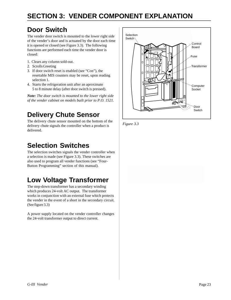
Page 23G-III Vender
affafds affafds
affafds
affafdsaffafdsaffafdsaff
afdsaffafds
Door Switch
SelectionSwitch
ControlBoard
Transformer
Fuse
ComputerSocket
SECTION 3: VENDER COMPONENT EXPLANATION
Door SwitchThe vender door switch is mounted to the lower right sideof the vender’s door and is actuated by the door each timeit is opened or closed (see Figure 3.3). The followingfunctions are performed each time the vender door isclosed:
1. Clears any column sold-out.2. Scrolls Greeting3. If door switch reset is enabled (see “Con”), the
resettable MIS counters may be reset, upon readingselection 1.
4. Starts the refrigeration unit after an aproximate5 to 8 minute delay (after door switch is pressed).
Note: The door switch is mounted to the lower right sideof the vender cabinet on models built prior to P.O. 1521.
Delivery Chute SensorThe delivery chute sensor mounted on the bottom of thedelivery chute signals the controller when a product isdelivered.
Selection SwitchesThe selection switches signals the vender controller whena selection is made (see Figure 3.3). These switches arealso used to program all vender functions (see “Four-Button Programming” section of this manual).
Low Voltage TransformerThe step-down transformer has a secondary windingwhich produces 24-volt AC output. The transformerworks in conjunction with an external fuse which protectsthe vender in the event of a short in the secondary circuit.(See figure 3.3)
A power supply located on the vender controller changesthe 24-volt transformer output to direct current.
Figure 3.3

G-III VenderPage 24
Vend Rack AssemblyThe vend rack assembly, located in the cooling compart-ment of the vender, is composed of twelve productcolumns; six located in the front (columns one throughsix) and six in the rear (columns seven through twelve).Both front and rear columns are double-depth columnsthat can be adjusted to single-depth to accommodatepackages other than 12 oz. cans. Different package typescannot be mixed within the same column.
Each column has an individual vend mechanism consist-ing of a rotating pivot, which is held in place by a spring-loaded release lever. On the opposite side of the columnare the product stops, both of which are adjustable to varythe clearance through the mechanism for various diameterpackages. These parts are mounted at the bottom of eachcolumn, and supported by rods through the vender’scenter support.
Beneath the rack and mounted to the left wall is a single
SECTION 3: VENDER COMPONENT EXPLANATION
Figure 3.5
vend motor and home sensor assembly. Connected to themotor’s drive sprocket and running below the centersupport is the drive chain and lever actuator assembly.
See “Vend Sequence” section for a complete descriptionof the vend operation.
Vend Rack ComponentsPIVOT: Located directly below each of the columns.Product in the column is retained between this pivot andthe product stops. Rotation of the pivot allows the bottompackage to dispense.
ADJUSTABLE PRODUCT STOPS: Two adjustableproduct stops, one long and one short, are located in eachcolumn. Both the long and short product stops can beadjusted to vend either large diameter packages or small

Page 25G-III Vender
SECTION 3: VENDER COMPONENT EXPLANATION
Figure 3.7
diameter packages. In any given column, both the longand the short adjustable product stops must be set to thesame diameter position (i.e. when vending 12 oz. cansfrom a column, both the long and the short adjustableproduct stops must be set to the “small” package posi-tion). For adjustment, see “Setting the Adjustable ProductStops” section of this manual.
PIVOT END AND RELEASE LEVER: A geared pivotend is inserted in the pivot. Its gear teeth engage with theteeth of the spring-loaded release lever thereby lockingthe pivot assembly until the release lever is pulled by themotor driven lever actuator.
PIVOT PAWL: A pivot pawl is used on each column’svend mechanism to reduce the backlash (“play”) betweenthe pivot assembly and the release lever. Pivot pawls aremounted behind the release lever springs.
ANTI-TILT SPRING: Prevents lowest can on fixedproduct stop from free vending if the vender is tilted orshaken by vandals.
VEND MOTOR ASSEMBLY: This assembly is com-prised of a vend motor and electronic encoder. These arecontrolled by the vender’s electronic controller. Theencoder confirms the motor’s positioning of the leveractuator.
HOME SENSOR: The home sensor is mounted directlyabove the vend motor sprocket on the vend motormounting bracket. It senses the lever actuator, using thisinformation to signal the controller that the leveractuator has reached the “home” position.
DRIVE CHAIN AND LEVER ACTUATOR: Attachedto the drive chain are the two sets of lever actuators. Thevend motor accurately positions the lever actuator tostrike the appropriate release lever.
IDLER BRACKET ASSEMBLY: Provides propertensioning for the chain assembly.
CHAIN STABILIZER: Provides support for the upperrun of the chain assembly.

G-III VenderPage 26
SECTION 3: VENDER COMPONENT EXPLANATION
The ElectronicRefrigeration Cycle1. The temperature sensor (electronic thermometer)
informs the board of the cabinet temperature. Theboards function is to interpret the temperature and turnon/off according to the program setting for refrigera-tion.
2. The control board activates the relay, turning on thecompressor and condenser fan motors. The controlboard also deactivates the relay, turning off thecompressor and condenser fan motors.
3. The compressor circulates refrigerant throughout thesystem by pulling low pressure refrigerant vapor fromthe evaporator coil, compressing it and forcing it intothe condenser coil.
4 The condenser, aided by the condenser fan motor,removes heat from the refrigerant as it flows throughthe condenser coil and releases it to the outsideenvironment. The dropping of the refrigeranttemperature changes the vapor to a liquid.
5. The capillary tube controls the amount of refrigerantreleased to the evaporator coil.
6. The evaporator coil allows the vaporized refrigerantto absorb heat from the cooling compartment as itflows through the coil.
7. The falling temperature in the cooling compartmentis caused by the continual circulation of refrigerantthrough the system, removing heat from the coolingcompartment and transporting it to the outsideenvironment.
Note: After the door is closed, there will be a 5-8 minutedelay before the refrigeration system will come on.

Page 27G-III Vender
NOTE: For proper operation, the vender must haveseveral packages in each column. The “Correct ChangeOnly” light will be on if a coin changer is present andsufficient coins are not in the tubes.
1. Credit inserted by the customer (coins, bills, debitcard) is registered by the controller. A customer canonly make a selection after sufficient credit has beeninserted to satisfy the sales price setting.
NOTE: At any time prior to reaching a vend price, acustomer may press the coin release lever on the outsideof the vender, cancelling credit and escrowing allinserted money. If a bill or cashbox coin is inserted, thisescrow is disabled. See “C-8 = Escrow Rule #1” foradditional information.
SECTION 4: VEND SEQUENCE OF OPERATION
Figure 4.1
Vend Sequence (Figure 4.1)
2. When the customer presses a selection switch, thecontroller senses a selection has been made andimmediately compares the amount of money vali-dated to the sale price of the selected product.
3. If the amount of money credited is the same orexceeds the sales price setting, the controller directsthe vend motor to move the chain (clockwiserotation) to position the lever actuator to the vendposition of the selected column.
4. After the position is verified by the encoder, the vendmotor is directed to reverse direction (counter-clockwise rotation). The chain drives the leveractuator (“rabbit”) to engage and activate the releaselever.

G-III VenderPage 28
SECTION 4: VEND SEQUENCE OF OPERATION
Sold OutIf the product selected is sold out, the digital display willindicate “SOLD OUT” and flash the “SOLD OUT” lamp,signalling the customer to make another selection orpush the coin return lever for a full refund. The “SOLDOUT” lamp will continue to flash until a successful vendis completed.
If the vender is totally sold out of product, illumination ofthe “SOLD OUT” lamp and the “SOLD OUT” message onthe digital display will be continuous. No money will beaccepted into the vender in a total sold out condition.
Figure 4.2
5. The upper tooth on the release lever disengages thepivot end, allowing the pivot assembly to rotate oneincrement. At that time, the lower tooth engages thepivot end, preventing further rotation.
6. When the vend motor again reverses (clockwiserotation), the lever actuator pulls away from therelease lever allowing the pivot to complete itsrotation. It is at this point that double-depth product(e.g. a 12 oz. can) is released to the customer. Thelever actuator strikes an additional time (two timestotal) for single-depth product (e.g. 20 oz. bottles).
7. The lever actuator (“rabbit”) continues running in aclockwise rotation until the forward one of the tworabbits reaches the home position.
8. A delivery sensor on the bottom of the delivery chuteindicates a product was delivered and signals thecontroller to reset and initiate a payback of change iftoo much money was inserted.
DOLLAR BILLS
Sold Out Light
CreditDisplay
CorrectChangeLight

Page 29G-III Vender
SECTION 5: MAINTENANCE
KO CONTROLLER
1 2 3 4 5 6 7 8 9 10 11 12 13 14 15 161 2 3 4 5 6
REDWHITEKEYBLACK
1 2 3 4 5 6 7 8 9 10 11 12 13
KEY
KEY
KEY
KEY
1 2 3 4 5 6 7 8
ZX1ZX5ZX3ZX4
ZX6KEY
1 2 3 4 5 6 7 8 9 10 11 12 13
WHITEBLACKREDGREENKEYGRAYPINKORANGEVIOLET
10 9 8 7 6 5 4 3 2 1
BLACKBROWN
REDKEY
BLACKKEY
RED
BROWN
8 7 6 5 4 3 2 1YELLOWGREEN
BROWNRED
18 17 16 15 14 13 12 11 10 9 8 7 6 5 4 3 2 1
GREYBLACK
KEYRED
6 5 4 3 2 1GRNDRED
BLACK
WHT/GRNWHT/BLU
PINK
WHT/ORG
WHITEYELLOWORANGE
GREEN
PURPLE
BLUEBROWN
18 17 16 15 14 13 12 11 10 9 8 7 6 5 4 3 2 1
CO
L 1
18 17 16 15 14 13 12 11 10 9 8 7 6 5 4 3 2 1
CO
L 2C
OL 3
CO
L 4K
EY
CO
L 5C
OL 6
CO
L 7C
OL 8
CO
L 9C
OL 10
CO
L 11C
OL 12
4 3 2 1BLA
CK
RE
D
NE
UT
RA
L
24 vA
C
P5
5 vD
C
NEUTRAL
5 vD
C
5 vDC
P3
P11
5 vD
C
5 vD
CP2
P1
NE
UT
RA
L
NE
UT
RA
L5 vD
C
P8
P7
5 vD
C24vD
C24vD
C24 vD
C
P6
P10
6 53
42 1
24 vA
C
P4A
P4
P9
READY TO VEND INDICATORS
LED
1 R150
J17
P15
9 8 7 6 5 4 3 2 1
PURPLEBROWN
ORANGE
GREENBLUERED
YELLOW
P16
KEY
BLACK
5 vD
C
5 vD
C
NE
UT
RA
L
CONTROLLER
S1
BLA
CK
RE
DG
RE
EN
WH
ITE
BR
OW
NB
LUE
Dex PhoneJack
Mode Switch& HHCInterface
L.E.D.Display
ChuteSensor
SelectionSwitches
Sold-Out IndicatorsMDB Power
Vend Motor/Encoder
RelayOutputs
Options
Home Sensor/Door Switch
TemperatureSensor
G-III VenderPage 30
SECTION 5: MAINTENANCE
WHAT TO ADJUST
Chute Sensor: The chute sensor has been pre-set atthe factory to sense product on the delivery chute. Toreturn the setting to the factory default, locate theadjustment screw, which is next to the service modebutton on the controller board (see view of G-III control-ler board). Slowly turn the adjustment screw clockwiseuntil the adjustment LED lights. Next, turn the screwcounter-clockwise until the adjustment LED barely goesout. Continue turning counter-clockwise 2 full turns fromthis point. Test by vend testing the exterior columns andwatch the chute sensor indicator light after the producthits the chute. The light should flash on and off.
This adjustment is necessary upon delivery chutereplacement, chute sensor replacement, controller boardreplacement, or to return the vender to the factory setting.

Page 31G-III Vender
Trouble ShootingThe G-III vender is equipped with a self-diagnostic feature to aid in the repair and maintenance of the vender. When
servicing the vender, pay close attention to the digital display. When the vender door is opened the electronics willbegin displaying any error codes that are stored in memory. If there are no errors, the display will read “nonE.” See“Four-Button Programming” section of this manual.
To enter the Service Mode, press and release the Service Mode Button located on the controller. The display willread “Eror.” If (ENTER) is pressed at the “Eror” prompt, the controller will enter the error display mode. If no errorshave occurred since the last error reset, the display will show “nonE.” If an error has been detected since the last errorreset, the display will show the first error summary code that has occurred.
If (ENTER) is pressed, the controller will display the detailed error for the summary code. The (UP) and (DOWN)buttons will cycle through any remaining error detail codes. If (ABORT) is pressed while displaying any detailed code,the controller will return to the summary code. If (ABORT) is pressed while displaying any summary code, the controllerwill return to the code level.
NOTE: When troubleshooting errors with peripherals, the appropriate peripheral service manual(s) should also beconsulted for further tests and corrective actions.
SECTION 5: MAINTENANCE
C HAr EE More than 255 escrow attempts Check escrow lever and If vender returns to Sales Mode(Coin Acceptor since the last coin was associated mechanisms. from Open-door Mode without input,Error) accepted. replace changer/acceptor.
Go to Open-door Mode and wait If it stays in Open-door Mode and thefor 30 seconds. manually-cleared error does notManually clear the error. reoccur, system may be OK.
nJ Coin Jam. Check changer/acceptor for If no obstructions are apparent,jammed coins or other replace changer/acceptor.obstructions.
LA Low Acceptance Rate Check changer/acceptor for If no obstructions are apparent, and(more than 20% of the last obstructions or dirt. acceptance appears to be OK, this255 coins were rejected may be an indication of cheatingas slugs) attempts.
Drop coins in Sales Mode or If no obstructions are apparent andTube Fill Mode to test coins do not accept, or acceptanceacceptance. rate is poor, replace changer/
acceptor.bUAL** bC Bill Communication Error If changer or card reader is If there is no “CC” or “rC” error:
being used, check for “CC” or 1) Check bill acceptor harness;“rC” errors. 2) Replace bill acceptor.Unplug machine and wait If there is a “CC” or “rC” error:at least five seconds. Plug 1) Check control board MDBmachine back in. harness.
bFuL Full bill stacker Ensure bill cashbox is empty If cashbox appears to be OK,and that the cashbox is replace bill acceptor.properly closed and in place.
biLL Motor is defective No test available. Replace bill acceptor.bJ Bill jam error Check bill acceptor for If no obstructions are apparent,
obstructions or dirt. replace bill acceptor.brCH Bill acceptor ROM checksum Unplug machine, wait at least If error does not clear, replace
error. five seconds, replug machine. bill acceptor.Manually clear the error.
bOPn Open cash box. Check that bill cashbox is closed If cashbox appears to be OK,and in correct position. replace bill acceptor.
bS Sensor error. Check bill acceptor for If no obstructions are apparent,obstructions or dirt. replace bill acceptor.
ERROR DETAILED ERROR CODE TEST PROCEDURE CORRECTIVE ACTIONAND DESCRIPTION
* Error Code must be manually cleared. See “Eror” section of this manual for detailed instructions.** These Error Codes will be automatically cleared when the validator reports no errors and is
enabled (the validator is “enabled” when it accepts money).

G-III VenderPage 32
CC Changer communication If card reader/bill acceptor is If there is no “rC” or “bC” error:error. being used, check for “rC” or 1) Check changer harness.
“bC” errors. 2) Replace changer.Unplug machine, wait at least If there is a “rC” or “bC” error:five seconds, and replug. 3) Check control board MDB harness.
tS Tube sensor error. Check changer tubes for Clear tube blockage, if found. If noblockage. blockage found, replace changer.
IC Inlet chute blocked error. Check inlet chute for blockage. Clear inlet chute blockage. If no(no coins sensed in the blockage found, replace changer.acceptor for over 96 hours) Drop coins in Sales Mode or If acceptance rate is acceptable,
Tube Fill Mode to test system is probably OK. If acceptanceacceptance. rate is low or changer will notManually clear the error. accept coins, replace changer.
tJXX Tube jam error. Check changer tubes and Clear blockage, if found. If nopayout for blockage. blockage found, replace changer.
CrCH Changer ROM Checksum Unplug machine, wait at least If error does not clear, replaceerror. five seconds, replug machine. changer.
Manually clear the error.CSF Changer’s scale factor is not Ensure that changer, bill If models are compatible, replace
valid for the machine acceptor, and card reader are changer.configuration.l all models for same country.
Unplug machine, wait at leastfive seconds, replug machine.
Crdr CrC Card reader communication If changer or bill acceptor is If there is no “CC” or “bC” error:(Card Reader error. being used, check for “CC” or 1) Check card reader harness;Error) “bC” errors. 2) Replace card reader.
Unplug machine, wait at least If there is a “CC” or “bC” error:five seconds, and replug. 1) Check control board MDB harness.
Crxy* Card reader error. No test available. Refer to card reader manual for(see card reader manual for corrective action.description of error codes)
OLn OC On line module Proper communicationsOn Line Module communication
(No communication for 5 sec.)OnC On line network Proper cummunications
communication(Network is not responding,OLM can not call out)
OI On line module internalproblem, causing improperfunctions (check sum, etc.)
rUnd rUC Remote vend Mech. Proper communicationsRemote Vend (No communication for 5 sec.)
S-d SdC Display device communication Proper communicationsSelection/ (No communication for 5 sec.)Display Device
SdXX Error code number “XX”device specific
rFrG SEnS Unplugged or defective Check the temperature sensor If the sensor is unplugged, replug it.temperature sensor error. connection of the control board If it is miswired, replace the
to make sure it is plugged in. temperature sensor.Check if it is wired properly and If the connections are bad, attemptthe pins are making contact. to repair them or replace the
temperature sensor if it isunrepairable.
SECTION 5: MAINTENANCE
ERROR DETAILED ERROR CODE TEST PROCEDURE CORRECTIVE ACTIONAND DESCRIPTION
* Error Code must be manually cleared. See “Eror” section of this manual for detailed instructions.

Page 33G-III Vender
SECTION 5: MAINTENANCE
ERROR DETAILED ERROR CODE TEST PROCEDURE CORRECTIVE ACTIONAND DESCRIPTION
CoLd Temperature three or more 1) Check the refrigeration unit If upon unplugging one of the whitedegrees below the before opening the vender’s wires, the unit stops:compressor cut out setting. main door to see if it’s running. 1) Check the temperature sensor
2) Open the vender’s main door reading; 2) Check Setp settings;and see if the unit cuts off. 3) Check two white wires3) Make sure the vender’s for shorts from the control board.door switch is working properly. 4) If upon unplugging one of the white4) Unplug one of the two white wires, the unit still runs; unplug one ofwires plugged into the black wires. If the unit stops, replacerefrigeration relay. refrigeration relay. If optional heater kit
is not installed, one may be required.5) If heater kit is installed and heaterdoes not turn on (heater relay doesnot click upon energizing with therelay test mode), check the twowhite wires from the board to theheater relay for voltage (should be+24VDC on one of the two wires).Check the other wire for continuitybetween the control board and therelay. If voltage is OK, replace relay.Otherwise, replace control board.
Hot Cabinet temperature is above Procede with normal refrigerationthe limit. trouble shooting . Refer to the
refrigeration flowchart.Htr Heating System has failed to Procede with normal refrigeration
increase 1 degree per hour trouble shooting . Refer to therefrigeration flowchart.
CnPr Compressor is not cooling 1) Check the refrigeration unit 1) If the unit is running, clear the errorwithin 30 minutes of turning on. before opening the vender’s main and see if it reoccurs. 2) If the display
door to see if it’s running. does not function as normal, check2) Open the vender’s main door the door switch circuit. 3,4) Changeand check the display to see that any settings if necessary and checkthe door switch is working as temperature sensor operation. 5) If thenormal. 3) Access the “rFrG” unit does not run (refrigeration relaysetup mode and check the “SetP” not clicking upon energizing with thesettings. 4) While relay test mode), check the two whitein the “rFrG” mode, change “dSP” wires from the board to theto ‘1’ to show the temperature refrigeration relay for voltage (shouldon the display during the greeting be 24+ VDC on one of the two wires).and see if it’s correct. Check the other wire for continuity5) While in the “Test” mode, between the control board andaccess the “rELy” mode relay. Note: The compressor relayand turn the compressor on. test mode must be on to check
voltage.
SEL SSXX Selection switch has been Check the selection switch Try to correct the problem if one of the(Selection closed for more than 25 number shown in the detailed three is found. If you can’t correct it,
seconds (where ‘XX’ indicates error code ‘XX’ to see if: 1) the then replace the component inselection switch number). button is sticking; 2) the switch question.
is sticking/defective; 3) theharness is wired wrong/shorted.
StS UAXX A column is unassigned. Access Space-to-Sales Mode Change space-to-sales setting as(Space-to and go to custom Space-to- required. In some situations, it maySales Error) Sales. by quicker to completely reset all
Check all selections for the Space-to-Sales.column showed in the detailederror description (XX).
* Error Code must be manually cleared. See “Eror” section of this manual for detailed instructions.
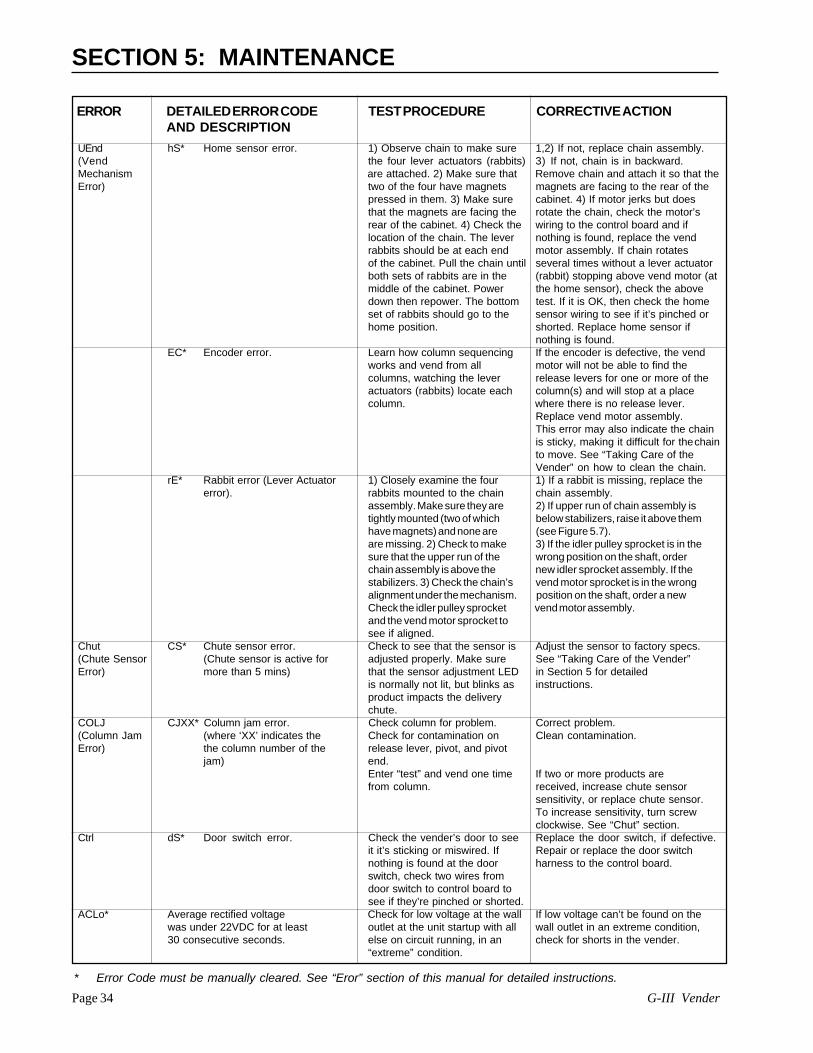
G-III VenderPage 34
SECTION 5: MAINTENANCE
ERROR DETAILED ERROR CODE TEST PROCEDURE CORRECTIVE ACTIONAND DESCRIPTION
UEnd hS* Home sensor error. 1) Observe chain to make sure 1,2) If not, replace chain assembly.(Vend the four lever actuators (rabbits) 3) If not, chain is in backward.Mechanism are attached. 2) Make sure that Remove chain and attach it so that theError) two of the four have magnets magnets are facing to the rear of the
pressed in them. 3) Make sure cabinet. 4) If motor jerks but doesthat the magnets are facing the rotate the chain, check the motor’srear of the cabinet. 4) Check the wiring to the control board and iflocation of the chain. The lever nothing is found, replace the vendrabbits should be at each end motor assembly. If chain rotatesof the cabinet. Pull the chain until several times without a lever actuatorboth sets of rabbits are in the (rabbit) stopping above vend motor (atmiddle of the cabinet. Power the home sensor), check the abovedown then repower. The bottom test. If it is OK, then check the homeset of rabbits should go to the sensor wiring to see if it’s pinched orhome position. shorted. Replace home sensor if
nothing is found.EC* Encoder error. Learn how column sequencing If the encoder is defective, the vend
works and vend from all motor will not be able to find thecolumns, watching the lever release levers for one or more of theactuators (rabbits) locate each column(s) and will stop at a placecolumn. where there is no release lever.
Replace vend motor assembly.This error may also indicate the chainis sticky, making it difficult for thechainto move. See “Taking Care of theVender” on how to clean the chain.
rE* Rabbit error (Lever Actuator 1) Closely examine the four 1) If a rabbit is missing, replace theerror). rabbits mounted to the chain chain assembly.
assembly. Make sure they are 2) If upper run of chain assembly istightly mounted (two of which below stabilizers, raise it above themhave magnets) and none are (see Figure 5.7).are missing. 2) Check to make 3) If the idler pulley sprocket is in thesure that the upper run of the wrong position on the shaft, orderchain assembly is above the new idler sprocket assembly. If thestabilizers. 3) Check the chain’s vend motor sprocket is in the wrongalignment under the mechanism. position on the shaft, order a newCheck the idler pulley sprocket vend motor assembly.and the vend motor sprocket tosee if aligned.
Chut CS* Chute sensor error. Check to see that the sensor is Adjust the sensor to factory specs.(Chute Sensor (Chute sensor is active for adjusted properly. Make sure See “Taking Care of the Vender”Error) more than 5 mins) that the sensor adjustment LED in Section 5 for detailed
is normally not lit, but blinks as instructions.product impacts the deliverychute.
COLJ CJXX* Column jam error. Check column for problem. Correct problem.(Column Jam (where ‘XX’ indicates the Check for contamination on Clean contamination.Error) the column number of the release lever, pivot, and pivot
jam) end.Enter “test” and vend one time If two or more products arefrom column. received, increase chute sensor
sensitivity, or replace chute sensor.To increase sensitivity, turn screwclockwise. See “Chut” section.
Ctrl dS* Door switch error. Check the vender’s door to see Replace the door switch, if defective.it it’s sticking or miswired. If Repair or replace the door switchnothing is found at the door harness to the control board.switch, check two wires fromdoor switch to control board tosee if they’re pinched or shorted.
ACLo* Average rectified voltage Check for low voltage at the wall If low voltage can’t be found on thewas under 22VDC for at least outlet at the unit startup with all wall outlet in an extreme condition,30 consecutive seconds. else on circuit running, in an check for shorts in the vender.
“extreme” condition.
* Error Code must be manually cleared. See “Eror” section of this manual for detailed instructions.

Page 35G-III Vender
SECTION 5: MAINTENANCE
ERROR PROBABLE CAUSE CORRECTIVE ACTION
COIN ACCEPTANCE/PAYOUT (RECORD ALLERRORS ON PAPER)
Coin mechanism will not No power to control board. Check to make sure the LED and theaccept coins. sign lighting are lit. Check fuse and
transformer.Harness from coin mech to board is cut Using a meter, check each wire foror disconnected. continuity and to ground.Short in coin mechanism. Unplug all connections from the
control board except the transformerand coin mech connections. Testacceptance. If it accepts, replug eachconnection one at a time and testacceptance after each.
Acceptor is dirty or other problem may exist Clean acceptor or contact your local(not tuned) coin mech dealer.Short in control board. If above procedures do not work,
replace controller.No acceptance or Coin return lever pressing down on acceptor’s Make sure changer is mountedRejects a percentage coin plunger. correctly and the coin return leverof good coins. is in the proper position.
Acceptor is dirty or foreign matter is in the path. Clean acceptor or contact dealer.Coin changer is improperly tuned (if tunable). Contact manufacturer for tuning.Defective controller board. Replace/test controller.
Always accepts coins IF NO CREDIT: Defective harness between coin Check harness for cut wires orbut gives erratic/no mech and control board (will have “CC” error). wrong/bad connections. Test eachcredit. wire for continuity or test to ground.
If found to be defective, replace.IF ERRATIC OR NO CREDIT: Acceptor or Replace coin mech and test. If OK,coin mech. then check the following:IF NO CREDIT: Defective controller. Replace/test controller.
Changer will not payout Defective harness between coin mech and Test vender’s manual coin payout. Ifcoins. control board. vender won’t pay out using the CPO
mode or during sales, checkharness for cuts, bad continuity orwrong connections. If defective,replace and test.
Defective coin mech. Replace coin mech and test. If it pays out,the coin mech was defective.
rAn rM* RAM error. No test available. If error shows ups frequently,replace control board
(Set Up Info and contact RoyalCorrupted) Vendors.
SF Scale factor error Check the connections of Make corrections to harness orchanger harness; make sure replace the changer if necessary.changer is plugged up andworking.
IS Inlet sensor blocked Check changer harnessing for cut,pinched or crimped wires. Replacechanger.
IB Inlet is blocked Check inlet for blockage; if nothing isfound.Check changer harnessing for cut,pinched or crimped wires. Replacechanger.
ERROR DETAILED ERROR CODE TEST PROCEDURE CORRECTIVE ACTIONAND DESCRIPTION
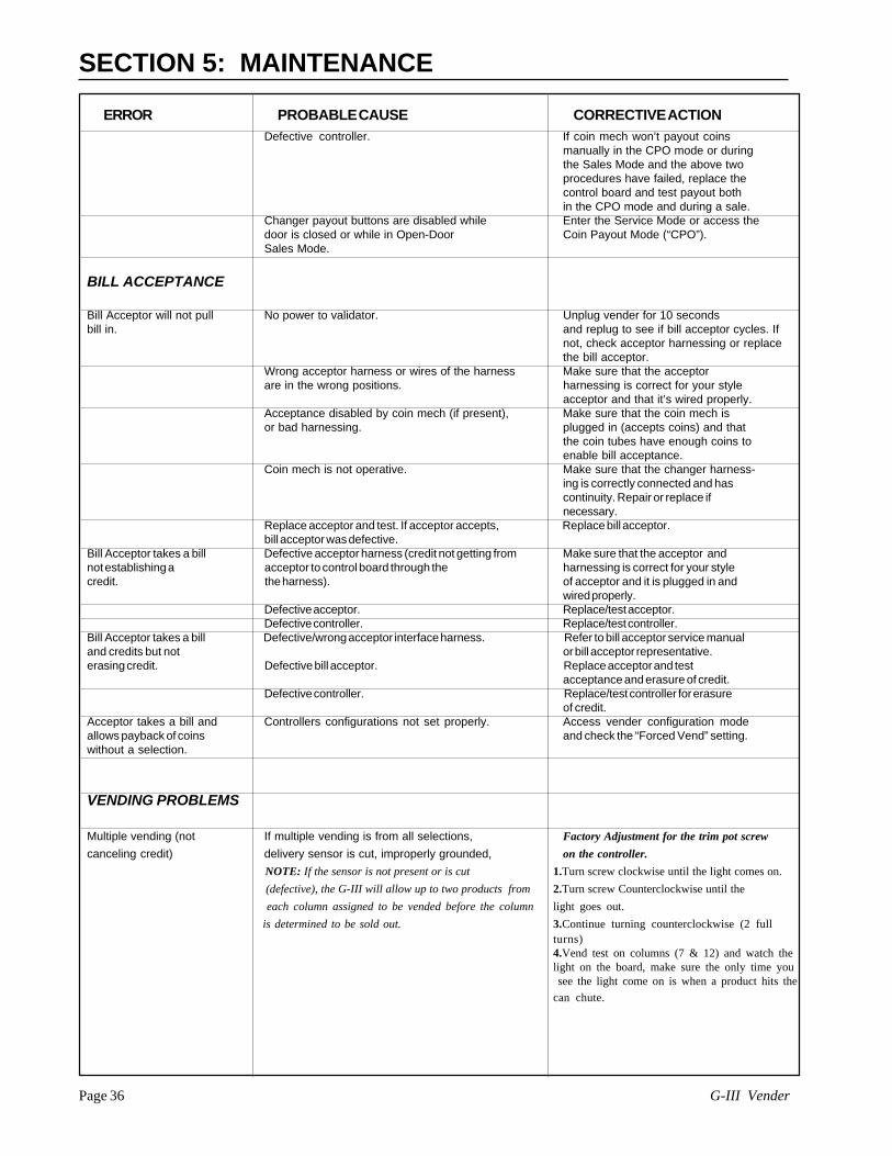
G-III VenderPage 36
ERROR PROBABLE CAUSE CORRECTIVE ACTION
SECTION 5: MAINTENANCE
Defective controller. If coin mech won’t payout coinsmanually in the CPO mode or duringthe Sales Mode and the above twoprocedures have failed, replace thecontrol board and test payout bothin the CPO mode and during a sale.
Changer payout buttons are disabled while Enter the Service Mode or access thedoor is closed or while in Open-Door Coin Payout Mode (“CPO”).Sales Mode.
BILL ACCEPTANCE
Bill Acceptor will not pull No power to validator. Unplug vender for 10 secondsbill in. and replug to see if bill acceptor cycles. If
not, check acceptor harnessing or replacethe bill acceptor.
Wrong acceptor harness or wires of the harness Make sure that the acceptorare in the wrong positions. harnessing is correct for your style
acceptor and that it’s wired properly.Acceptance disabled by coin mech (if present), Make sure that the coin mech isor bad harnessing. plugged in (accepts coins) and that
the coin tubes have enough coins toenable bill acceptance.
Coin mech is not operative. Make sure that the changer harness-ing is correctly connected and hascontinuity. Repair or replace ifnecessary.
Replace acceptor and test. If acceptor accepts, Replace bill acceptor.bill acceptor was defective.
Bill Acceptor takes a bill Defective acceptor harness (credit not getting from Make sure that the acceptor andnot establishing a acceptor to control board through the harnessing is correct for your stylecredit. the harness). of acceptor and it is plugged in and
wired properly.Defective acceptor. Replace/test acceptor.Defective controller. Replace/test controller.
Bill Acceptor takes a bill Defective/wrong acceptor interface harness. Refer to bill acceptor service manualand credits but not or bill acceptor representative.erasing credit. Defective bill acceptor. Replace acceptor and test
acceptance and erasure of credit.Defective controller. Replace/test controller for erasure
of credit.Acceptor takes a bill and Controllers configurations not set properly. Access vender configuration modeallows payback of coins and check the “Forced Vend” setting.without a selection.
VENDING PROBLEMS
Multiple vending (not If multiple vending is from all selections, Factory Adjustment for the trim pot screwcanceling credit) delivery sensor is cut, improperly grounded, on the controller.
NOTE: If the sensor is not present or is cut 1.Turn screw clockwise until the light comes on. (defective), the G-III will allow up to two products from 2.Turn screw Counterclockwise until the
each column assigned to be vended before the column light goes out. is determined to be sold out. 3.Continue turning counterclockwise (2 full
turns)4.Vend test on columns (7 & 12) and watch thelight on the board, make sure the only time you see the light come on is when a product hits thecan chute.

Page 37G-III Vender
ERROR PROBABLE CAUSE CORRECTIVE ACTION
SECTION 5: MAINTENANCE
Depth setting not set correctly in SdEP mode. Enter SdEP Mode and check setting (May be set to single depth.) to be correct. Refer to “SdEP”
section of this manual.Mechanical error. Check for correct operation of the pivot,
pivot end and release lever. Verify that bothadjustable product stops are set to thecorrect position for the package type.
Wrong product vending Misload by vender loader. Ensure that all product within eachupon selection. column is the same.
Space-to-Sales not set properly. Look for StS error. Check or resetSpace-to-Sales.
Miswired selection. Check the wiring from thecontroller to the selection switches.
Bad encoder (motor assembly). Watch vend cycle from under stack(“UEnd” error should be displayed) mechanism. Know the columns
you’re vending from (preferably onecolumn assigned to one selection). If thelever actuators (rabbits) do not come closeto this column upon vending, change themotor assembly.
No vend upon selection. Delivery sensor too sensitive Check to see if the delivery chute sensorDry vend (no refund). or a column is jammed or sold out. adjustment LED is constantly on. If
so, adjust it back to factory setting. See“Taking Care of the Vendor” in Section 5.Check adjustable product stops to ensurethat both are set to the correct position.
Defective controller board. Unplug the sensors connection fromthe control board. Watch LED. If theadjustment LED stays on, replacedefective controller.
Will vend from some but Select button, switch, or harnessing. Check the selection switch. And tracenot all columns (allows the selection harnesses back to therefund or 2nd choice). control board. Replace if necessary.
Defective encoder. Watch vend cycle from under stack(“UEnd” error should be displayed) mechanism. Know the column you’re
vending from (preferable one columnassigned to one selection). If thelever actuators (rabbits) do not come closeto this column upon vending, change themotor assembly.
Complete sold out Home sensor, chain or lever actuators (rabbits). Pull chain out into middle of columncondition, motor rotates and unplug power to door then replug.chain several times then If the motor rotates the chain severalsays Sold Out. times without finding a home position,
check/change home sensor chainand lever actuators (rabbits).
Complete sold out condition Timer is enabled or StS has been cleared (CLr) Disable timer control or program StS
MISCELLANEOUSPROBLEMSDisplay shows sold out Door switch wiring incorrectly connected or Check for cuts on the 2 door switchimmediately upon pressing cut/pinched. wires going from the switch to theselect button of full column control board. Also check for bad(sold out not clearing). connections.
Door Switch. Check the door switch to see if it’sdefective. Use a meter to measure forcontinuity between Com./N.O. positionsand Com./N.C. positions.
Control Board. Check control board by shorting acrossthe two pins for the door switch at the(P5) pin position on the board. Does this clearthe sold out condition? If it doesn’t, replacethe control board.
Vender Appears Dead; No Defective main harness. Secondary power Repair main harness or replace. RepairDigital Display and No harness to the transformer. Lights defective. or replace secondary power harness.Lights (See Interconnect Drawing, this section)

G-III VenderPage 38
SECTION 5: MAINTENANCE
ERROR DETAILED ERROR CODES AND CORRECTIVE ACTIONPROBABLE CAUSE AS DISPLAYED
No Digital Display; Transformer not properly connected or Check transformer connection toVender Lights On defective. Check power from transformer
controller board. (See InterconnectDrawing, this section) Replace ifnecessary.
Defective display or display harness. Check display and displayharness and replace if necessary.Defective controller board. Replace controller board.
Vender Scrolls Changer out of tune. See “Tuning Changer.”Message On Display Defective changer. Replace changer.But Does Not Accept Defective controller board. Replace board.MoneyVender Accepts Defective changer. Replace changer.Money But Does NotCredit Defective controller board. Replace board.Vender Accepts And Defective selection switch. Replace selection switch.Credits Money ButDoes Not Vend (Does Defective selection switch harness. Repair or replace harness.Not Indicate A Defective controller board. Replace controller board.Sold-Out.Vender Delivers Wrong Vender loaded wrong. Correct loading.Product Vender space-to-sales set wrong. See “StS.”
Defective encoder. Replace motor assembly.Defective controller board. Replace controller board.
Flashing 8888’s on the LED. Chips on control board not seated properly. Seat the chips down properly.
Bad LED connection. Scrape the pins on the LED.
Defective control board. Unplug everything from the board exceptthe LED and power in. If the 8888’s remainthen replace the board.
Defective components. If the 8888’s have disappeared from theprevious step, then begin plugging upharnesses one at a time. Replacewhatever causes the 8888’s to reappear.
Solid 8888’s on the LED. Defective LED. Replace LED and/or harness.
Defective control board. Replace control board.
“Out of Order” on the LED. Defective home sensor, chain assembly, or control board. Make sure the lead rabbit is at thetop of the vend motor (home position).Make sure the magnet on the lead rabbitsface towards the rear of the cabinet.Check voltage at the control board (P5)position. Check for 5VDC across pins 1and 3. The two wires will be red andblack. If voltage is found check for thesame voltage at the bottom of the door.This will be a three way connector.Replace whatever it is that you do not findvoltage. If the correct voltage is found,replace the home sensor.
ELECTRONICREFRIGERATIONRefrigeration unit will not run. Defective temperature sensor. 1. Check connection.The cabinet temperature reads 2. Replace temperature sensor.255F or 17F.
Vender will not display a Defective temperature sensor.temperature when DSP isset to 1.
Defective control board
Unplug the existing sensor and plugthe new sensor up and ground it to theboard. Hold down the door switch andsee if the LED displays a temperature.
If it does not display a temperature,replace the board.

Page 39G-III Vender
ERROR PROBABLE CAUSE CORRECTIVE ACTION
SECTION 5: MAINTENANCE
.Refrigeration unit will not run. Defective unit. Plug the unit directly to the wall outlet tosee if it runs and cools. If not, thenreplace the unit.
Unit will only run in the Defective door switch. Open and close the door to make surecompressor relay test mode. the LED scrolls. If not then check the door(Located under tESt) switch, harness, or control board.
Defective temperature sensor. Follow the same steps detailed above aboutthe temperature sensor.
Wait the 5 to 10 minute delay once the door is closed. Wait to see if the unit comes on.
Defective control board. If unit still does not come on, then replacethe control board.
Unit will not run in the Defective control board. Check for 24 VDC across pins 1and 3compressor relay test mode. of control board. These are the large set**NOTE: Leave the of pins that connects with the regulatorcompressor relay test mode on, in board. If no voltage or incorrect voltage isorder to check for voltage. found, then replace the control board.
Defective adapter harness. Check wires 1 and 3 for the same voltageas above. Replace if incorrect.
Defective regulator board. Check for 24VDC at the top of the regulatorboard across pins 1 and 3. Replace ifincorrect.
Defective relay harness. Check for 24VDC at the relay across the 2wires with pink connectors. Replace ifincorrect.
Defective relay. Check for 110VAC on the contact side ofthe relay. Replace if incorrect.
Refrigeration unit constantly runs. Defective door switch. Upon opening the door, the LED should notread “Ice Cold…”. If it does, then replacedoor switch.
Defective control board. Replace the control board.
Adapter harness wired incorrectly. Check to make sure the harness is wired 1through 6. Correct the wires if wiredwrong.
Defective relay. Contacts are welded together Unplug one of the wires with the pinkconnectors from the relay. Also unplug the110VAC side of the relay. If the unit cutsoff, then replace the relay.
Defective main power cord. If the unit continues to run after unpluggingeverything from the relay, replace thejunction block.
Evaporator freeze-up. Check the steps above if the unit runs when the door See above.is open.
Evaporator fan not running Check wiring to evaporator fan. Check for110VAC. If no voltage is found, replace thejunction block. If the correct voltage isfound, replace the evaporator fan motor.
Air leaks around the inner door or port body. Check for condensation around the innerdoor for air leaks. Ensure the door istightened down far enough. Make sure theport door is not held open.
Mullen area not properly sealed (area where the Apply permagum.harnesses enter the cabinet).
Drain tube clogged. Check to make sure water can freely flowthrough the drain tube.
SETP set too low. Increase the SETP to 40°F
Refrigeration unit not charged properly. Replace unit.

G-III Vender
Page 40
SECTIO
N 5: R
EFRIG
ERATIO
N FLO
W C
HA
RT
yes yes yes yes
no
yes
no no no
no
no
no
yes no
yes
yes
no
yes
no
no
yes
yes
yes
no
yes
no
yes
yes
yes
no
no
yes
no
yes
no
no
yes
no
yes
no
yes
close vendors doorand wait approx.
5 minutes to see ifref. unit comes on
wait to see if the ref.unit stops when thedisplay registers the
"cuto" setting 28 f
startfinal phase
FINAL PHASE
no yes
yes
did the unit come
on?
did the unit quit running?
change main control
board
nochange
main controlboard
problemsolved
check "setp 35 f"settings and make surethat "dsp" is set to "1"to track the ref. unitstemperature progress
E L EC T RON IC
R E F R I G E R A T ION
TROUBLESHOOTING
F L O W C H A R T
open door &record errors*
check voltage tothe evap. fan motor
check to ensure thatthe evap. coils are
not frozen (if so, thaw)
plug unit intowall outlet
use controller"cnp" relay test
plug all harn. back. unplugconnection at regulatorboard for the ref. relay
replace unit
did unitstart and
continue torun?
do youget 24-28 DC volts?
Is the setp 35 f?
check voltagebetween pins 1 & 3
from regulatorboard** to relay
check voltagebetween pins 1 & 3from main board**to regulator board
check harness
and connections
between reg. boardand relay
do youget 24-28 DC volts?
do youget 24-28 DC volts?
check voltage attwo white relaywires (st1 & 2)**
repair harnessor replace
temp. sensor
repair harnessor replace
temp. sensor
change "dsp" setting to "1" to show evap.air temp. on display
is the temp. shown
accurate?replace
regulatorboard
replacemain control
board
is the temp. shown
accurate?
is harness cut, smashed
or disconnect.?
check temp. sensorharness for cuts
replace defectivetemperature sensor
go tofinal phase
go tofinal phase
go tofinal phase
go tofinal phase
go tofinal phase
go tofinal phase
go tofinal phase
go tofinal phase
go tofinal phase
fixfaulty relay harnessing
is theevaporatorfan motorrunning?
is theevap motor
receiving 110?
replacerefrigeration
relay
go tofinal phase
go tofinal phase
go tofinal phase
replacerefrigeration
relay
go tofinal phase
replaceevaporatorfan motor
go tofinal phase
go tofinal phase
replacemain wiring
harness
repair/replaceevap. fan blade
and/or motor
is unitrunning
with doorclosed?
did unitstart and
continue torun?
open door &record errors*
did unitquit running
upon openingdoor?
did unitquit
running?
is refrig.unit off?
is a short
found?
unplug 1 of the 2 whiterelay wires (st1 & 2)from the refrig. relay
replacerefrigeration
relay
replacemain control
board
look for a shortin one of thesetwo white wires
go tofinal phase
is refrig.unit off?
plug all harn. back. unplug connection at main cont. board for the reg. board
replaceregulator
board
is theevap. fan
blade intact?
replacedefective temp.
sensor
programcorrect settings
change "dsp" setting to "1" to show evap.air temp. on display
is the temp. shown
accurate?
is harness cut, smashed
or disconnect.?
check temp. sensorharness for cuts
Setp 35 f
go tofinal phase
go tofinal phase
go tofinal phase
go tofinal phase
repair harnessor replace
temp. sensor
is thissetting
correct?
change main control
board
*normal errors are "cnp" and "cold" for this type of problem.**for voltage to be read. you must first enable the compressor (via the "rely" mode. ***for this type of problem it is recommended that the settings be setp 35 f.
START HERE
Rev. B6/99
Start
Check Regulator
BoardHarness
Check for110 V at
power cord

Page 41G-III Vender
SECTION 6: OPTIONAL EQUIPMENT
G-III OptionsKits For Vending Additional PackagesThese kits were the latest available at the time of publica-tion of this manual. For the latest information on kitsthat will enable the G-III to vend other packages, pleasecontact Royal Vendors’ Customer Service Department.
SURGE/BOLT 20 OZ. PACKAGEIn general, all G-IIIs with serial numbers after 1415XX-XXXX are capable of vending the Surge/Bolt package asdelivered from the factory. If you are unsure as to theconfiguration of your vender or want to order the Surge/Bolt package kit for earlier venders, please contact RoyalVendors’ Customer Service Department.
POWERADE 20 OZ. PLBIn general, all G-IIIs with serial numbers after 1381XX-XXXX are capable of vending the Powerade 20 oz. PLBpackage as delivered from the factory. Some earlier serialnumber venders are also Powerade capable. If you areunsure as to the configuration of your vender or want toorder the Powerade kit for earlier venders, please contactRoyal Vendors’ Customer Service Department.
EVIAN AND NAYA 500 ml (16.9 oz.) WATERBOTTLESAll G-IIIs, no matter when they were manufactured, willrequire a kit to vend the Evian and Naya 500 ml waterbottles. Please contact Royal Vendors’ Customer ServiceDepartment for information.
Hand Held Computer (HHC)The G-III Vender interfaces with the Direct Exchange/Uniform Communications Standard (DEX/UCS) andDEX/UCS Compatible Hand-held Computers (HHC).The HHC may be used to program the G-III Vender’svend price and (STS), as well as other pertinent MIS andsecurity information. The HHC interfaces to the vender’scontroller board via the computer socket located near thetop of the main door. Once the HHC is connected andmeets initial communication requirements, it may then beused to program the G-III Vender. For more information onthe HHC, see separate HHC manual.
External MIS PlugAn external MIS Plug is available with Kit #842099Install in accordance with kit instructions.
Light KitKit # 141160
Heater KitKit # 141130
Override Key Switch KitKit # 231107
U-Hinge Retrofit KitsKit # 164110, BlackKit # 294110, Red
Enclosed Coin Cup Kits (Landscape Venders)Kit# 231575, Narrow PortKit# 303140, Wide Port

G-III VenderPage 42
explodedviews

Page 43G-III Vender
SECTION 7: EXPLODED VIEWS
Item No. Description Part Number Qty.
1 Inner Door Assy, 72” 211604 1-79” 210606 1-72” Narrow* 289610 1-79” Marketing* 290605 1-72” Marketing* 291605 1-72” Narrow Marketing* 293605 1
2 Gasket, Inner Door, 72” 815032 1-79.5” 815033 1
3 Port Door Frame 815191 14 Port Door 815192 15 Port Door Rod 811028 16 Lock Nut, #6-32 905006 13-6 Port Door Assy 810053 17 Burst Open Latch 812002 18 Bushing, 1.38” 916003 29 Clamp, Cable, 1” 916004 110 Rivet, 3/16” Diameter 908002 211 Bushing, Inner Door 815026 212 Hinge, Inner Door (Top) 010520 113 Nut, #8-32 905001 214 Screw, Self-drilling, #8-18x1/2” 902001 5015 Hinge, Bottom, Door 010550 116 Bolt,1/4-20x1” 901003 217 Interconnect Decal, G-III 931356 118 Vender Controller/Space-To-Sales, Decal, G-III 931225 1
-E.V.S. 931352 1
4
16
15
11
6
5
14
3
7
8
8
9
10
1
2
1411
1312
17
18
*1504 & after(except 1504-00001-00130)
Inner Door Assembly
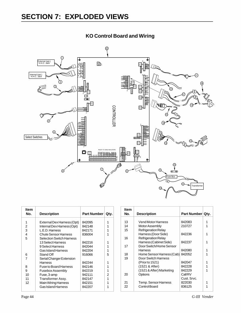
G-III VenderPage 44
SECTION 7: EXPLODED VIEWS
Item No. Description Part Number Qty.
1 External Dex Harness (Opt) 842095 12 Internal Dex Harness (Opt) 842148 13 L.E.D. Harness 842171 14 Chute Sensor Harness 836004 15 Selection Switch Harness
13 Select Harness 842216 19 Select Harness 842044 1Gas Island Harness 842204 1
6 Stand Off 916066 57 Serial Changer Extension
Harness 842244 18 Fuse to Board Harness 842146 19 Fusebox Assembly 842219 110 Fuse, 3-amp 942111 211 Transformer Assy. 842147 112 Main Wiring Harness 842151 1
Gas Island Harness 842207 1
ItemNo. Description Part Number Qty.
13 Vend Motor Harness 842083 114 Motor Assembly 210727 115 Refrigeration Relay
Harness (Door Side) 842236 116 Refrigeration Relay
Harness (Cabinet Side) 842237 117 Door Switch/Home Sensor
Harness 842080 118 Home Sensor Harness (Cab) 842052 119 Door Switch Harness
(Prior to 1521) 842047 1(1521 & After) 842228 1(1521 & After) Marketing 842229 1
20 Options Call RVCust. Srvc.
21 Temp. Sensor Harness 822030 122 Control Board 836125 1
KO Control Board and Wiring
1 2
3 4
5 6
REDWHITEKEYBLACK
1 2
3 4
5 6
7 8
9 1
0 11
12
13
KEY
KEY
KEY
KEY
1 2
3 4
5 6
7 8
ZX1ZX5ZX3ZX4
ZX6KEY
1 2
3 4
5 6
7 8
9 1
0 11
12
13
WHITEBLACKREDGREENKEYGRAYPINKORANGEVIOLET
10
9 8
7 6
5 4
3 2
1
BLACKBROWN
REDKEY
BLACKKEY
RED
BROWN
8 7
6 5
4 3
2 1YELLOW
GREENBROWN
RED
18
17
16
15
14
13
12
11 1
0 9
8 7
6 5
4 3
2 1
GREYBLACK
KEYRED
6 5
4 3
2 1GRND
REDBLACK
WHT/GRNWHT/BLU
PINK
WHT/ORG
WHITEYELLOWORANGE
GREEN
PURPLE
BLUEBROWN
18 17 16 15 14 13 12 11 10 9 8 7 6 5 4 3 2 1
CO
L 1
18 17 16 15 14 13 12 11 10 9 8 7 6 5 4 3 2 1
CO
L 2C
OL 3
CO
L 4K
EY
CO
L 5C
OL 6
CO
L 7C
OL 8
CO
L 9C
OL 1
0C
OL 11
CO
L 12
4 3 2 1BL
AC
K
RE
D
NE
UT
RA
L
24
vA
C
P5
5 v
DC
NEUTRAL
5 v
DC
5 vDC
P3
P11
5 v
DC
5 v
DCP
2P
1
NE
UT
RA
L
NE
UT
RA
L5
vD
C
P8
P7
5 v
DC
24
vD
C2
4v
DC
24
vD
C
P6
P1
0
6 53
42 1
24
vA
C
P4
AP
4
P9
READY TO VEND INDICATORS
LE
D1 R
15
0
J17
9 8
7 6
5 4
3 2
1
PURPLEBROWN
ORANGE
GREENBLUERED
YELLOW
P1
6
KEY
BLACK
5 v
DC
5 v
DC
NE
UT
RA
L
CONTRO
LLER
S1
BL
AC
KR
ED
GR
EE
N
WH
ITE
BR
OW
NB
LU
E
Select Switches
External (opt.)H.H.C. Jack
Fuse Box
Transformer
21
13
1
3
5
4
8
14
11
12
9
10
6
20
15
17
18
19
2
Internal (opt.)H.H.C. Jack
7
16
22
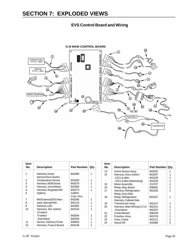
Page 45G-III Vender
SECTION 7: EXPLODED VIEWS
EVS Control Board and Wiring
Item No. Description Part Number Qty.
1 Harness, Home 842080 1Sensor/Door Switch
2 Temperature Sensor 822030 13 Harness, MDB Serial 842079 14 Harness, Vend Motor 842083 15 Harness, Regulator Bd 842273 16 Options Call RV
Cust. Srvc.7 MIS External DEX Harn. 842095 18 Jack, Internal HHC 842110 19 Harness, LED 842081 110 Harness, Sel. Switch, 842216 1
13 select-9 select 842044 1-Gas Island 842204 1
11 Sensor, Delivery Chute 836004 112 Harness, Fuse to Board 842146 1
ItemNo. Description Part Number Qty.13 Home Sensor Assy. 842052 114 Harness, Door Switch 842047 1
-1521 & after 842228 1-1521 & after (Marketing) 842229 1
15 Motor Assembly 210727 116 Relay, Reg. Board 836081 117 Harness, Refrigeration 842235 1
Relay, Door Side18 Relay, Refrigeration 842237 1
Harness, Cabinet Side19 Transformer Assy. 842147 120 Harness, Main Wiring (117v) 842151 1
-Gas Island 842207 121 Control Board 836109 122 Fusebox Assy. 842219 123 Fuse, 3-amp 942111 224 Stand Off 916066 5
921909-1
Select Switches
External (opt.)H.H.C. Jack
InternalH.H.C. Jack
Fuse Box
Transformer
1
2
3
4
7
89
10
11
12
13
14
5
6
15
16 17
18
19
20
G-III MAIN CONTROL BOARD
21 22
23
24
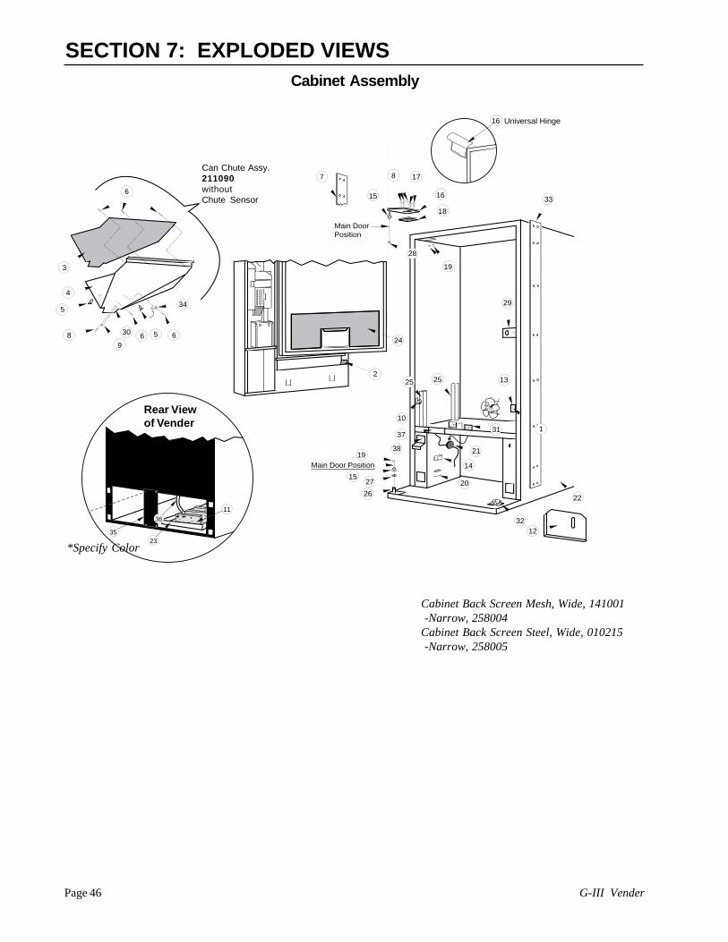
G-III VenderPage 46
SECTION 7: EXPLODED VIEWS
*Specify Color
fggfdfgfffggfdfgfffggfdfgfffggfdfgfffggfdfgfffggfdfgfdfgfffggfdfgfffggfdfgfffggfdfgfffggfdfgfffggfdfgfffggfdfgfffggfdfgfffggfdfgfffggfdfgfffggfdfgfffggfdfgfdfgfffggfdfgfffggfdfgfffggfdfgfffggfdfgfffggfdfgfffggfdfgfffggfdfgfffggfdfgfffggfdfgfffggfdfgfffggfdfgfdfgfffgfggfdfgfffggfdfgfffggfdfgfffggfdfgfffggfdfgfffggfdfgfdfgfffggfdfgfffggfdfgfffggfdfgfffggfdfgfffggfdfgfffggfdfgfffggfdfgfffggfdfgfffggfdfgfffggfdfgff
fggfdfgfffggfdfgfffggfdfgfffggfdfgfffggfdfgfffggfdfgfdfgfffggfdfgfffggfdfgfffggfdfgfffggfdfgfffggfdfgfffggfdfgfffggfdfgfffggfdfgfffggfdfgfffggfdfgfffggfdfgfdfgfffggfdfgfffggfdfgfffggfdfgfffggfdfgfffggfdfgfffggfdfgfffggfdfgfffggfdfgfffggfdfgfffggfdfgfffggfdfgfdfgfffgfdfgfffggfdfgfffggfdfgfdfgfffgfdfgfffggfdfgfffggfdfgfdfgfffg
affafdsaffafds
affafds
affafds
affafdsaffafdsaffafdsaffafdsaffafds
2
19
Main Door Position
Main Door Position
15
8 17
16
18
19
29
2226
1527
31
33
28
32
21
14
20
1325 25
10
371
12
7
3
4
5
530
34
6
89
6 6
Rear View of Vender
3523
11
36
24
38
16 Universal Hinge
Can Chute Assy.211090withoutChute Sensor
Cabinet Assembly
Cabinet Back Screen Mesh, Wide, 141001 -Narrow, 258004Cabinet Back Screen Steel, Wide, 010215 -Narrow, 258005
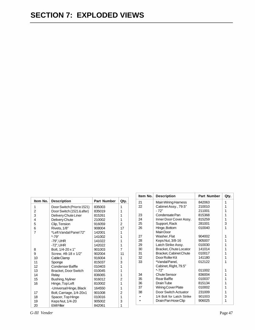
Page 47G-III Vender
Item No. Description Part Number Qty.1 Door Switch (Prior to 1521) 835003 12 Door Switch (1521 & after) 835019 13 Delivery Chute Liner 815261 14 Delivery Chute 210002 15 Clip, Tension 916059 26 Rivets, 1/8” 908004 177 *Left Vandal Panel 72” 142001 1
*-79” 141002 1-79”, UHR 141022 1-72”, UHR 142022 1
8 Bolt, 1/4-20 x 1” 901003 79 Screw, #8-18 x 1/2” 902004 1110 Cable Clamp 916004 111 Sponge 815037 312 Condenser Baffle 010403 113 Bracket, Door Switch 010045 114 Relay 836065 115 Bushing, Nyliner 916012 216 Hinge, Top Left 810002 1
-Universal Hinge, Black 164550 117 Bolt, Carriage, 1/4-20x1 901008 218 Spacer, Top Hinge 010016 119 Keps Nut, 1/4-20 905002 320 EMI Filter 842061 1
Item No. Description Part Number Qty.
21 Main Wiring Harness 842063 122 Cabinet Assy., 79.5” 210010 1
- 72” 211001 123 Condensate Pan 815368 124 Inner Door Cover Assy. 815259 125 Support, Rack 281001 326 Hinge, Bottom 010040 1
Main Door27 Washer, Flat 904002 128 Keps Nut, 3/8-16 905007 129 Latch Strike Assy. 010030 130 Bracket, Chute Locator 141014 131 Bracket, Cabinet Chute 010017 132 Door Roller Kit 141180 133 *Vandal Panel, 012122 1
Cabinet, Right, 79.5”*-72” 011002 1
34 Chute Sensor 836004 135 Rear Baffle 010037 136 Drain Tube 815134 137 Wiring Cover Plate 010002 138 Door Switch Actuator 231009 1 • 1/4 Bolt for Latch Strike 901003 3 • Drain Pan Hose Clip 906025 1
SECTION 7: EXPLODED VIEWS

G-III VenderPage 48
SECTION 7: EXPLODED VIEWS
Item No. Description Part Number
15 Coin Box Housing, CDC 27350316 Anti-Theft Plate, CDC 23150417 Coin Cup, CDC (after 1349) 231505
-prior to 1349 16150518 Coin Return Lever Assembly 16159319 3/64 Diameter Cable 91103220 Cable Sleeve (at each end) 90601521 Support Bracket/Coin Chute 16153722 Changer Vault W/A 16152323 Port W/A, CDC 231510• Changer Vault Door (not shown) 161534• Change Label, CDC (not shown) 931341• Label, Open Bottle Slow (not shown) 931355• Decal, Sec. Plate, CDC (not shown) 845467• Coin Deflector 161526
Item No. Description Part Number
1 Changer Vault Brace 1615182 Coin Chute Assy., CDC, 79.5” 161590
-72” 1625403 T-Handle Brace (See Detail A) 1415134 Button Lever Assembly 1615945 Coin Chute Bracket, 79.5” 161527
-72” 1625026 Hopper Mounting Bracket 1615158 Select Panel Plate 1615129 Plastic Coin Box, CDC 81534710 W/A Port Brace 16154111 Lock Cylinder Cover 16153212 Coin Insert Assembly, Coke, 161930
Electronic, CDC, 79.5”Coin Insert Assembly, Coke, 162920Electronic, CDC, 72”
13 Coin Hopper 81501514 Coin Box Coin Chute W/A 231519
* Coin box w/a CC CDC 6 in. = part no. 161570* Coin box w/a GIII CDC 8 in. = 231550
DETAIL “B”
DETAIL “A”
9
18
1
21
2
5
4
3
2019
106
8
22
DETAIL "A"
4L.E.D. DISPLAY 3
11
COIN MECH
DETAIL "B"
15
14
16 1723
1310
12
17
Center Door ChangerAssembly (for the Narrow Port)
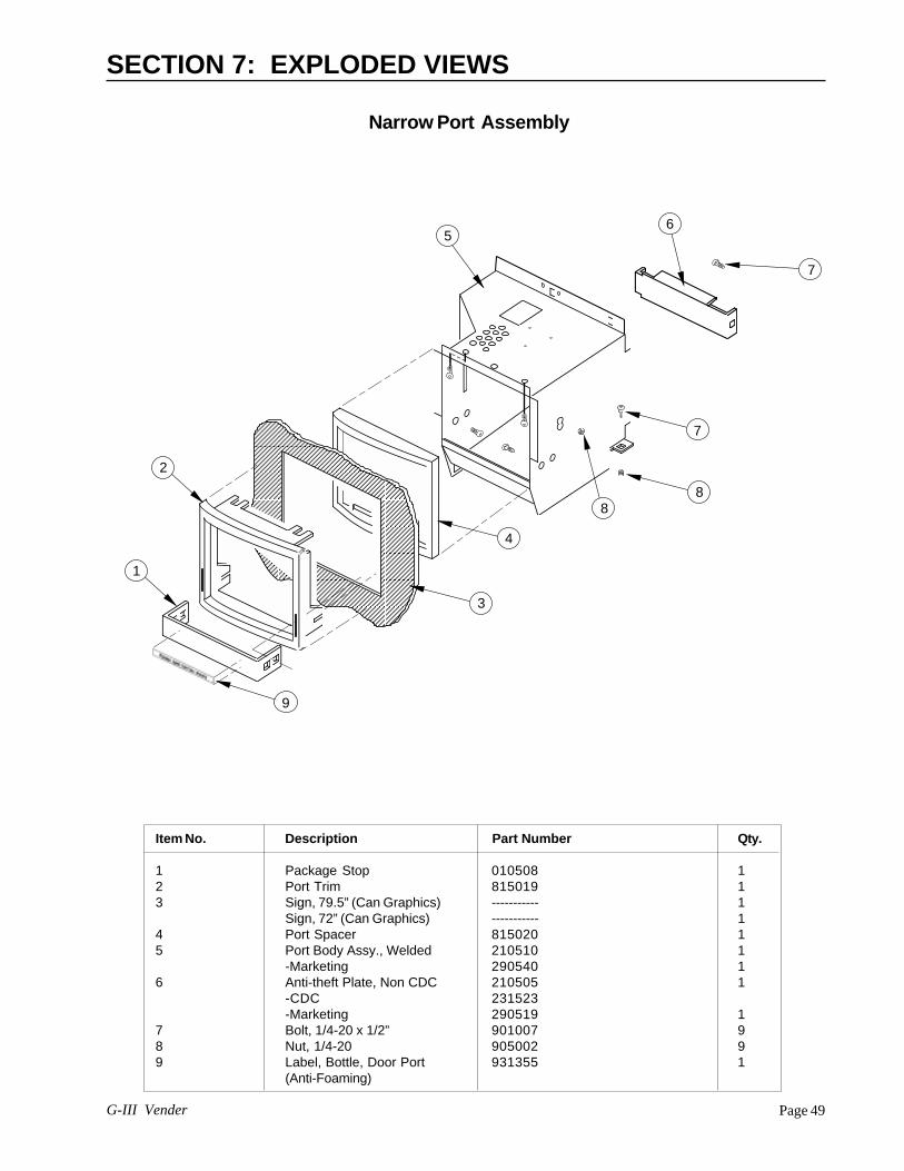
Page 49G-III Vender
SECTION 7: EXPLODED VIEWS
Item No. Description Part Number Qty.
1 Package Stop 010508 12 Port Trim 815019 13 Sign, 79.5” (Can Graphics) ----------- 1
Sign, 72” (Can Graphics) ----------- 14 Port Spacer 815020 15 Port Body Assy., Welded 210510 1
-Marketing 290540 16 Anti-theft Plate, Non CDC 210505 1
-CDC 231523-Marketing 290519 1
7 Bolt, 1/4-20 x 1/2” 901007 98 Nut, 1/4-20 905002 99 Label, Bottle, Door Port 931355 1
(Anti-Foaming)
7
7
88
4
3
9
1
2
56
Narrow Port Assembly

G-III VenderPage 50
SECTION 7: EXPLODED VIEWS
Item No. Description Part Number Qty.
1 Coin Cup 231505 12 Port Body Assy., Welded 303540 1
-Non CDC 305510 13 Anti-theft Plate, CDC 303503 1
-Non CDC 305501 14 Port Spacer 815248 15 Port Trim 815249 16 Package Stop 273508 1
12
3
4
5
6
Wide Port Assembly

Page 51G-III Vender
SECTION 7: EXPLODED VIEWS
COIN MECH
DETAIL "A"
1
2
3
4
5
6
7
8
9
8 10
Item No. Description Part Number
1 Coin Chute Assy., CDC, 79.5” 161590-72” 162540
2 Cable 9110323 Coin Chute Support, WP 3035074 Changer Vault W/A 3035065 Changer Vault Brace 161518
Item No. Description Part Number
6 Coin Return Hinge Bracket 2905437 Coin Return Lever 1615078 Coin Hopper, WP 3035029 Port Brace 01051510 Coin Box Chute, WP 303501
Center Door Changer forthe Wide Port
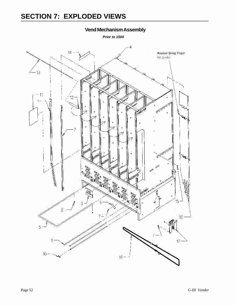
G-III VenderPage 52
SECTION 7: EXPLODED VIEWS
Vend Mechanism Assembly
4
Prior to 1504

Page 53G-III Vender
37
31
22 (1504 and after)(1504 and after)
22 (Pr(Prior to 1504)ior to 1504)
21
20 (Pr(Prior to 1504)ior to 1504)
19
20 (1504 and after) (1504 and after)
25
23
SECTION 7: EXPLODED VIEWS
Item Description Part No. Qty.No.1 Retainer, Front, L, 79.5 210745 6
- 72” 211712 62 Retainer, Front, R, 79.5” 210746 6
-72” 211713 63 Decal, Case Support 931195 14 Vend Stack Assembly 79.5 210725 1
-72 211711 15 Case Support 811026 16 Screw, Self-drilling* 902004 27 Screw, #8-32x3/8” 901011 118 Rod Retainer, Rotating 810046 79 Shaft, Pivot/Product Stop 803032 1810 Rod Retainer, Sliding 915184 611 Sheet, Anti-friction 915197 2412 Spacer, Column 915194 613 Bolt, Rack Retainer 811027 114 Rubber Strip 915199 715 Lock Nut, Retainer, #8-32 905004 116 Retainer Assy., Rear, 79.5” 210707 6
- 72” 211714 617 Idler Bracket Assembly 210726 118 Chain/Actuator Assembly 210730 1
19 Screw, Stab., #6-32x1.5” 901023 2(prior to 1504)-**Screw 1.25” (1504 & after) 901041 2
20 Stabilizer Assembly 210744 2(prior to 1504)-**Stabilizer (1504 & after) 915266 2
21 Lock Nut, Stabilizer, #6-32 905006 2(prior to 1504)-**Nut (1504 & after) 905018 2
22 Insert, Divider (prior to 1504) 815242 12-**Insert, Divider (1504 & after) 815252 12
23 E-ring, Release Lever 906013 1224 Release Lever 915125 1225 Spring, Release Lever 914008 1226 Pawl, Anti-Rotation 915188 1227 Bearing, Pivot 915206 1228 Pivot 813010 1229 Pivot End, Front 915207 630 Pivot End, Rear 915208 631 Spacer, Prod. Stop, .5” 915181 632 Product Stop, Long 813016 12
Adjustable33 Spacer, Prod. Stop, 1.85” 915250 1234 Spring, Anti-tilt 915186 1235 Product Stop, Short 813006 12
Adjustable36 Spacer, Prod. Stop, 1.25” 915182 1237 Spacer, Front, 1” 915264 12*Clip, Hitch-pin (part no. 906,023) in units 1435 and after.
ITEMS 27, 28 & 29 = PIVOT ASSEMBLY, FRONTPart No. 210750 (1379 and after)Part No. 147730 (prior to 1379)
ITEMS 27, 28 & 30 = PIVOT ASSEMBLY, REARPart No. 210760 (1379 and after)Part No. 147740 (prior to 1379)
Item Description Part No. Qty. No.
**1504 & after (except 1504-0001-00130)
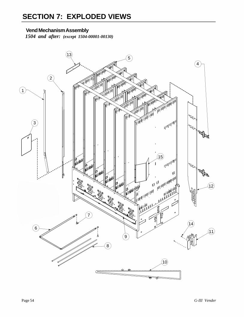
G-III VenderPage 54
SECTION 7: EXPLODED VIEWS
Vend Mechanism Assembly1504 and after: (except 1504-00001-00130)
1
2
3
4
5
7
6
8
10
11
14
9
13
12
54
15

Page 55G-III Vender
SECTION 7: EXPLODED VIEWS
Item No. Description Part No. Qty.
1 Retainer, Front, L, 79.5” 210745 6- 72” 211712 6
2 Retainer, Front, R, 79.5” 210746 6-72” 211713 6
3 Sheet, Anti-friction 915197 244 Retainer Spring Finger 815251 125 Vend Stack Assy, 79.5 210738 1
-72 211711 1-72 Narrow 289610 1
6 Case Support 811026 17 Screw 902004 28 Shaft, Pivot/Product Stop 803032 189 Rod Retainer 281709 1
-Narrow 283704 110 Chain/Actuator Assembly 210730 1
-Narrow 283710 111 Idler Bracket Assembly 210757 112 Retainer Assy., Rear, 79.5” 210707 6
-72 211714 613 Rubber Strip 915199 714 Screw, #8-32x3/8” 901011 415 Stack Stiffener, Wide 281704 1
-Narrow 283702 1
1504 and after:(except 1504-00001-00130)

G-III VenderPage 56
SECTION 7: EXPLODED VIEWS
Item No. Description Part Number Qty.
1 Vend Motor Assembly 210727 12 Home Sensor Assembly 842052 13 Lock Nut, Home Sensor, #6-32 905006 24 Bracket, Motor ---- 15 Sprocket 916034 16 Motor and Encoder ---- 17 Cover, Motor ---- 18 Harness, Motor/Encoder ---- 19 Screw, Machine, #10-24x.50” ---- 410 Nut, #10-24 ---- 211 Lock Nut, #10-24 ---- 2
Vend Motor Assembly
(Without Home Sensor)

Page 57G-III Vender
Item No. Description Part Number Qty.
1 Bracket, Idler (before run 1504) 210703 1-*Bracket, Idler (1504 & after) 281713 1
2 Shaft/Sprocket, Idler Assy (Before run 1504 095770 2-*Shaft/Sprocket, Idler Assy (1504 & after) 281716 2
3 Bearing, Idler Shaft 915079 44 Spring, Idler 914021 2
SECTION 7: EXPLODED VIEWS
*1504 and after (except 1504-00001-00130)
3
2
1
3
4
2
3
Idler Bracket Assembly210726 (Before run 1504)
*210757 (1504 and after)

G-III VenderPage 58
1
9
1113
14
15
33
33
32 30
36
25
37
29
31
26
27
28
21
18
33
33
17 16
2423
35
36
7
54
3
6
2
36
34
38
39
22
12
10
19
110 Volt AC power connections for the validator and ballast
24 Volt AC fuse box for transformer
110 Volt vend motors fuse box
24 Volt Multi-Drop Bus connection
20
8
SECTION 7: EXPLODED VIEWS
Select Panel Assembly

Page 59G-III Vender
24 Coin Chute Cover 81500225 Splash Guard - Coke 81516926 Coin Ramp 14150827 Spring-Select Button 91400428 Select Button - Coke 81516529 Switch, Miniature 83500130 Carrier Strip Assy. 81516731 Button Panel 815168
-Gas Island 28550732 Retaining Strap 141507
- Gas Island 28550433 Sems Screw, #8-32x3/8" 90101134 Screw, Self-drilling #8x1/2" 902001
w/ 1/2" Washer35 Sew Screw #6-32x3/8" 90100436 Nuts, Keps #8-32 90500137 Nuts, Keps 1/4-20 90500238 Wire Tie, Large (4”) 91600739 Sold Out Spring 914003 • Bottom Coin Chute Assy 010594
Non CDC (Landscape) • Coin return:
-Bushing (Coin return) 803030 -Hex Jam Nut (Coin return) 905019 -9/16 Internal Tooth Washer 904013 (Coin return)
• PC Board Housing 095530 • Splash Guard 815169 • Hole-Block Lock Cover 141509
Item No. Description Part Number
1 Welded Assy., 79" 307510- 72" 308510- 79” Narrow 306510- 72” Gas Island 309510
2 Flush Mount Pop-Out 812176T-Handle Assy.(Items 3, 4, 5, 6, 7 & 20)-*T-Handle Assy. 812289-*T-Handle Assy, Stainless 812291
3 T-Handle Body n/a4 Spring n/a5 T-Handle Stud n/a6 Retaining Ring n/a7 Pin/T Handle Stud n/a8 T-Stud Sealer Washer 9152589 Button, Coin Return Lever 80303110 Retaining Ring, 5-32" 90600511 Roller Pin - Door Lifter 81100212 Hinge - Coin Return Lever 14150613 Coin Return Lever 14150414 Catch Basin Bill Validator Assy 09559015 Catch Basin Drain Tube 92503816 Decal 93143917 W/A POS Plate, metal 23157918 Security Shelf 14151219 Fuse Bracket I.E.C. 14152220 “T” Handle Housing n/a21 “T” Handle Brace 14151322 Lever Stop 14151423 Coin Chute 815001
SECTION 7: EXPLODED VIEWS
Item No. Description Part Number
*1504 and after(except 1504-00001-00130)
Select Panel Assembly
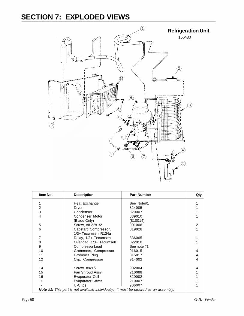
G-III VenderPage 60
1
2
3
4
513
OPTIONAL
98 7
10
12 11 11
1214
16
15
6
SECTION 7: EXPLODED VIEWS
Item No. Description Part Number Qty.
1 Heat Exchange See Note#1 12 Dryer 824005 13 Condenser 820007 14 Condenser Motor 839010 1
(Blade Only) (810014)5 Screw, #8-32x1/2 901006 26 Capstart Compressor, 819028 1
1/3+ Tecumseh, R134a7 Relay, 1/3+ Tecumseh 836065 18 Overload, 1/3+ Tecumseh 822010 19 Compressor Lead See note #110 Grommets, Compressor 916015 411 Grommet Plug 815017 412 Clip, Compressor 914002 4----14 Screw. #8x1/2 902004 415 Fan Shroud Assy. 210088 116 Evaporator Coil 820002 1 • Evaporator Cover 210007 1 • U-Clips 906007 1Note #1: This part is not available individually. It must be ordered as an assembly.
156430Refrigeration Unit

Page 61G-III Vender
13
1
2
7
6
10
5
4
11
12
14
15
9
17
18
3
8
16
20
1921
22
23
24
26
25
27
28
SECTION 7: EXPLODED VIEWS
Item No. Description Part Number
1 Door w/a Coke 79" Wide 307510 - 72" Wide 308510
2 Control Panel, 9 Select, Non CDC 143510(Before 1525) - 7 Select,Narrow (Before 1525) Non CDC 141530 - 9 Select ( after 1525) non CDC 143507 - 7 Select,Narrow (after 1525) Non CDC 141577 - Gas Island (Before 1525) 285520 - Gas Island (After 1525) 285530
3 Security Plate W/A, non CDC 1415504 Validator Cover, Coke 0115185 Security Plate Decal 8453966 T-bolt, 1/4-20x1" LG 9010377 Button, Coin Return Lever 803031
-Coin Return Bushing 8030308 Hex Jam Nut 9/16-18 UNF2A 9050199 Sems Screw, #8-32x3/8" LG 90101110 Coin Plate, Coke 14151611 Keps Nut, 1/4-20 905002
12 Hold-Down Angle 12350513 Decal Select Button 84538314 Coin Cup Mounting Plate W/A 12355015 Carriage Bolt, 1/4-20x1/2" LG 90100716-18 LED Assembly 01059319 Transformer 84214720 Harness to Board, 24-volt 84214621 Fuse Box Assy. 01216522 Keps Nut #8-32 90500123 T-Screw, #8-32x3/4” 90100124 Lock Cover Hole Block 14150925 Keps Nut 90500126 T-Screw 90100127 Coke Trim Filler, Top 81531128 Coke Trim Filler, Bottom 815312 • Bottom Coin Chute Assy, Non CDC 010594 • Ballast Assy, 72” CDC 232520 • Ballast Assy, 72” & 79” Non CDC 010950 • Ballast Assy, 79” CDC 231560• Transformer Baffle, Wide 010047• Transformer Baffle, Narrow 258003
Item No. Description Part Number
Control Panel, 9 Sel, W/A CDC163520 (Before 1525)
Control Panel, 7 Sel, W/A CDC161530 (Before 1525)
Control Panel, 9 Sel, CDC163580 (1525 & after)
Control Panel, 7 Sel, CDC161577 (1525 & after)
Security Plate, W/A CDC161550
Decal Sec. Plate, CDC845467
Vandal-Resistant Door
Complete Plastic Trim Kits:1. 79” Wide- 141590 (Before 1525)2. 72” Wide- 142530 (Before 1525)3. 72” Narrow- 149540 (Before 1525)
1. 79” Wide- 143509 (1525 & after)2. 72” Wide- 142507 (1525 & after)3. 72” Narrow- 259560 (1525 & after)
Black Christmas Tree- 916009

G-III VenderPage 62
SECTION 7: EXPLODED VIEWS
9 Metal Bolt On Trim: ---Top and Bottom/All Wide 171502Left, 79.5” 171507Top and Bottom Right, 79.5” 171505Top and Bottom/Enclosure, 17151279.5”
10 Plastic Trim: ---Top and Bottom/All Wide 171518Top Right, 79.5” 171516Top and Bottom/Enclosure, 17151979.5”Bottom Right, 79.5” 171517Left Trim, 79.5” 171514
11 1/4-20 Kep Nut 905002(Attaches to Item 12)
12 1/2-20X 1” T-Bolt 90103713 Coin Cup W/A 123550
Item No. Description Part Number
1 Door Weld Assy., 79” 307510-72” 308510
2 Vandal Panel Cover, 79.5” 171101-72” 172001
3 *Right Vandal Panel, 79” 010519*- 72” 011501
4 Bolt On Control Panel, 9 Sel. 143510- 7 Sel. 141530
5 P.O.S. Window 8150076 Lexan Panel - flavor card 1715227 Front Security Plate, 9 Sel. 183510
Front Security Plate, 7 Sel. 1815108 P.O.S. Lexan Cover 171523
NOTES: 1. For other trim and door sizes, contact your local Royal Vendors’ representative.2. *Specify Color
Item No. Description Part Number
cont
rol p
anel
#2
p o
s#2
cont
rol p
anel
#1
p o
s#1
1912
10
4
2
6
8
7
13
5
3
11 Tuff Guy / Steel Door Vandal Resistant
Call yourRoyal representativefor Lexan and/orSteel Door Sign
Venders builtbefore PO 1519A

Page 63G-III Vender
SECTION 7: EXPLODED VIEWS
Item No. Description Part Number
1 Door Weld Assy., CDC, 72” 304510Door Weld Assy., CDC, 79” 303520
2 Vandal Panel Cover, 79.5” 171101Vandal Panel Cover, 72” 172001
3 *Right Vandal Panel, 79” 010519*Right Vandal Panel, 72” 011501
4 Bolt On Control Panel, 1635809 Sel., CDCBolt On Control Panel, 1615307 Sel., CDC
5 P.O.S. Window 8150076 Lexan Panel 1715227 Front Security Plate, 9 Sel. 173510
Front Security Plate, 7 Sel. 1715108 P.O.S. Lexan Cover 171523
Item No. Description Part Number
9 Metal Bolt On Trim:Top and Bottom/All Wide 171502Left, 79.5” 171507Top and Bottom Right, 79.5” 171505Top and Bottom/Enclosure, 17151279.5”Right Trim, 79.5” 171506
10 Plastic Trim:Top and Bottom/All Wide 171513Top Right, 79.5” 171516Top and Bottom/Enclosure, 17151279.5”Bottom Right, 79.5” 171517Left Trim, 79.5” 171514
11 1/4-20 Kep Nut 905002(Attaches to Item 12)
12 1/4-20 x 1” T-Bolt 901037
NOTES: 1. For other trim and door sizes, contact your local Royal Vendors representative.2. *Specify Color
cont
rol p
anel
#2
p o
s#2
cont
rol p
anel
#1
p o
s#1
19
12
10
2
7
5
6
8
4
3
11Tuff Guy / Steel DoorCenter Door Changer
Call yourRoyal representativefor the Lexan and/orSteel Door Sign
Venders builtbefore PO 1519A

G-III VenderPage 64
SECTION 7: EXPLODED VIEWS
Item No. Description Part Number
1 Sign Support 1715362 #8-32 Screw (2) 9010113 1/4 Keps Nut 9050024 P.O.S. Window 8150075 Control Panel, 9 select CDC 163580
-Non CDC 1435076 Front Security Plate, 9 Sel. 183510
-7 Select 1815107 CokeTrim Filler, Bottom 8153128 Coke Trim Filler, Top 8153119 Lexan Panel - Flavor Card 17152210 P.O.S. Lexan Cover 171523
Venders builtPO 1519A and after
Steel Door 1 2
3
4
5
6
7
8
9
1011
1213
14
Item No. Description Part Number
11 Trim Kit Assembly 79” 143509 -72” 142507 -72” Narrow 259560
12 T-Screw 90100113 Keps Nut 90500114 Carriage Bolt (3 Req.) 90105615 Vandal Panel Cover, 79” 171101
-72” 172001
15

Page 65G-III Vender
SECTION 7: EXPLODED VIEWS
Item No. Description Part Number Qty.
1 Fan Blade 810045 12 Nut, 1/4-20 905002 13 Silencer ----- 14 Motor, 35W/115V 839028 15 Machine Screw #8-32x1/2” 901038 36 Fan Plate 010058 17 Well Nut, #8-32 905026 38 Fan Mounting Bracket 010057 19 Sems Screw #8-32x3/8” 901011 31-9 Fan Assembly 210400 1
2
1
3
5
6
7
4
8
9
Evaporator Fan Motor Assembly

G-III VenderPage 66
SECTION 7: EXPLODED VIEWS
Miscellaneous Assemblies, Gas Island
Main Door Position15
8 17
16
18
19
30
22
33
34
35
29
19Main Door Position
12
26
1528
32
6
36
38
40
39
41
37 37
3
4
5
531
2
6
89
6 6
Zard Zard
Megalopolis Megalopo
Megalopolis Megalopo
Rear View of Vender
13
21
14
20
Switch Box
23
7
10
10
24
25
27
1
11
11

Page 67G-III Vender
SECTION 7: EXPLODED VIEWS
Item No. Description Part Number
Miscellaneous Assemblies, Gas Island
Item No. Description Part Number
1 Wiring Cover Plate 0100022 Delivery Chute Sensor 8360043 Delivery Chute Liner 8152614 Delivery Chute 2100025 Tension Clips 9160596 Rivets 1/8" 9080047 Cabinet Back Screen, Gas Island 2850098 Bolts 1/4-20x1" 9010039 Screw #8-18x1/2" 90200410 Access Door, Gas Island 28500111 Stand W/A, 16" Gas Island 28501012 Door Assembly 72", Gas Island 28555013 Cable Clamp, Gas Island 84220014 Toggle Switch Cover, Gas Island 84219915 Nyliner 91601216 Top Hinge, Left 81000217 Carriage Bolt 90100818 Top Hinge Spacer 01001619 Keps Nut 1/4-20 90500220 Toggle Switch, Gas Island 83501621 Handy Switch Box, Gas Island 84219822 Cabinet Assembly 285050
23 Back Decal, Gas Island 84808124 Cable Clamp 91600425 Left Vandel Panel 14200126 Main Door Bottom Hinge 01004027 Pop Rivot 90800328 Flat Washer 90400229 Keps Nut 3/8-16 90500730 Latch Strike Assembly 01003031 Bracket, Chute Locator 14101432 Can Chute Tie Bracket 01001733 P.C. Board Cover Assembly 81526034 P.C. Board Housing 09553035 Right Cabinet Vandal Panel 72" 01100236 Door Roller Kit 14118037 Rack Support 28100138 Main Wiring Harness, Gas Island 84220739 EMI Filter 84206140 Relay 83606541 Door Switch Bracket 010045 • Key Pad Cover Plate,Gas Island 285503 • Wiring Diagram, Gas Island 931359

G-III VenderPage 68
6
3
4
5
8 9
30
6 6
2
5
Front View of The Coca-Cola Marketing Vender
45
46
14
24
affafds affafds
affafds
affafdsaffafdsaffafdsaff
afdsaffafds
13
12
43
11
47
48
32
33
51
44
25
20
7
55
21
23
Main Door Position
Main Door Position
15
8 17
19
29
2226
1527
31
34
35
37
39
38
40
3636
19
49
28
50
52
1
41
18
16
42
53
54
10
56
SECTION 7: EXPLODED VIEWS
(Miscellaneous Assemblies)Coca Cola Marketing Vender

Page 69G-III Vender
SECTION 7: EXPLODED VIEWS
Coca Cola Marketing Vender (Miscellaneous Assemblies)
1 Wiring Plate Cover 0100022 Delivery Chute Sensor 8361083 Delivery Chute Liner, Wide 815299
Marketing4 Delivery Chute, Wide Marketing 2900015 Tension Clips 9160596 Rivets 1/8" 9080047 Coin Box Housing, Marketing 8153478 Bolts 1/4-20x1" 9010039 Screw #8-18x1/2" 90200410 Lamp Bracket (bottom),Marketing 29053411 Coin Box , Marketing 29055012 Door Assy. Wide, Marketing 72”, 291550
bottle-Wide Marketing 72”, can 291551-Wide Marketing 79”, bottle 290593-Wide Marketing 79”, can 290594
13 Inner Door Assembly, Wide 291605Marketing 72"-Wide Marketing 79” 290605-Narrow Marketing 293605
14 Vend Rack Assembly, Marketing 291710Wide 72"- Wide 79” 290710-Narrow 289710
15 Nyliner 91601216 Top Hinge, Left, Marketing 81005717 Carriage Bolt 90100818 Top Hinge Spacer 01001619 Temperature Sensor, Marketing 82204120 Lamp Bracket (Top) Marketing 29053321 Control Board Mounting Panel 29052322 Cabinet Assembly 72”, Wide 291020
Marketing-79” Wide, Marketing 290020
23 Transformer Assy 84214724 Rod Retainer, Wide 281709
-Narrow 28370425 Water Diverter (Top Hinge) 290575
Marketing26 Main Door Bottom Hinge, 290010
Marketing27 Flat Washer 90400228 Keps Nut 3/8-16 90500729 Latch Strike Assembly 28101030 Bracket, Chute Locator 09500231 Can Chute Tie Bracket 141014
32 Control Board 83610933 Fuse Box Assy 842219
Fuse Holder Assy 84221934 Right Cabinet Vandal Panel 72" 291004
Marketing-79", Marketing 290004
35 Door Roller Kit 14118036 Rack Support 28100137 Main Wiring Harness 84206338 EMI Filter 84206139 Relay 83606540 Door Switch Bracket 01004541 Door Switch (prior to 1521) 83500342 Door Switch (*1521 & after) 83501943 Ballast Assy., Marketing 72” 291540
-79” 29059044 Port W/A, Marketing 290540
Anti-Theft Plate, Marketing 29051945 T-Handle Assy, Marketing 812271
-1504 & after 81229046 Select Button, Marketing 81527247 Water Diverter, Marketing 29057448 Burst Open Latch Strike Assy, 290546
Marketing49 Rain Guard, Wide Marketing 29059250 Left Vandal Panel 79", 290003
Marketing-72", Marketing 291003-79”, UHR 141022-72”, UHR 142022
51 Right Vandal Panel 79" 290585Marketing- 72", Marketing 291585
52 Cable Clamp 91600453 Ballast Panel, Marketing 29053154 Ballast Panel Brace, Marketing 290532
-Narrow 29250555 Port Brace, Marketing 29052156 Universal Hinge, Red 294550 • Ballast Panel Assy., Marketing 290571 • Top Lampholder, H.O. 842001 • Bottom Lampholder, H.O. 842002
*Except 72” Marketing Venders,which start PO 1528 and after.
Item No. Description Part NumberItem No. Description Part Number

G-III VenderPage 70
SECTION 7: EXPLODED VIEWS
Coca Cola Marketing Vender
7
6
8
9
1
4
10
11
3
14
5
10
2
12
13
15
16
17
815.272.011
Rear View of Button
18
19
19

Page 71G-III Vender
1 Sign Trim Top, Wide 72”/79”, 290587Marketing -Narrow 292508 -Clip-On Wide 291539 -Clip-On Narrow 292516
2 Lexan Ad Panel, 79” 848575 -72” 848574
3 Sign Trim Center 79”, Marketing 290596 -72” 291509 -Clip-On, 72” 291537 -Clip-On, 79” 292514
4 Sign Trim-Flat, Marketing 290597 -Clip-On 291545
5 L.E.D. Assembly 2915256 Control Panel Assy, Marketing 290599
-Control Panel W/A 2905207 Button Panel Assy. with 290566
Harness, Marketing8 Port Trim, Marketing 2905169 Coin Cup, Marketing 29052210 Sign Trim Lt/Rt 79”, Marketing 290589
-72” 291508 -Clip-on, 72” 291536 -Clip-On, 79” 292513
Item No. Description Part Number Item No. Description Part Number
SECTION 7: EXPLODED VIEWS
11 Sign Trim Bottom, Wide, Marketing 290588 -Narrow 292509 -Clip-On, Wide 291538 -Clip-On, Narrow 292515
12 Lexan POS Window, Marketing 81530413 Feature Button Bracket, Marketing 29056914 Sign Trim-Flat, Marketing 290597
-Clip-On 29154115 Port Panel Sign, Marketing 84827816 Validator Mounting Plate Assy 84400817 Validator Decal, Marketing 93136018 Spring 91402419 Select Button 815272 • Feature Button Bracket Decal 831349 • Control Panel Decal,Marketing 848233 • Control Panel Decal, Marketing 848295
(with lock cover holes) • Red Christmas Tree 916084 • Red Carriage Bolt 901051 • Red Pop Rivet 908015 • Validator Filler 931361 • Validator Cover with Studs 291526
Note: Clip-On Trim started with P.O. 1529B and after

G-III VenderPage 72
Lamp
SECTION 7: EXPLODED VIEWS
1
2
3
4
5
6
7
8
910
11
13
12
16
14
15
17
18
19
21
22
20
Rear Door Miscellaneous Assemblies
23
24
25
26
27

Page 73G-III Vender
Item No. Description Part Number Item No. Description Part Number
16 T-Stud Sealer Washer 91525817 Bulkhead, Top 29051518 Validator Support 29154319 Cable Sleeve 90601520 Coin Return Hinge Bracket 29054321 Button Channel, Marketing 29050622 Cable 91103823 Feature Button Bracket 29051224 Feature Button Plate 29053825 Bulkhead, Bottom 29051426 Coin Chute Support 29054227 T-Bolt 901052 • Validator Guard, Marketing 290101 • Painted Hole Block Cover 290108 • LED Shroud, Marketing 929031 • Select Button Spring, Marketing 914024
Coca Cola Marketing Vender (Rear Door Miscellaneous Assemblies)
1 Control Panel Strap, Marketing 2905822 Validator Divider, Marketing 2905413 LED Assy, Marketing 2915254 Coin Return Lever Assy, 291529
Marketing5 Lever Stop, Marketing 2905446 Control Panel Brace, Marketing 2905297 Changer Shield, Marketing 2905258 Coin Return Lever, Marketing 1615079 Changer Door Assy, Marketing 29056210 Select Switch 83500111 Switch Carrier Strip, Marketing 81527312 Coin Chute Assy, Marketing 29056413 T-Handle Brace, Marketing 29053914 Hole Block Cover, Marketing 29055515 POS Window Plate, Marketing 290535
SECTION 7: EXPLODED VIEWS
G-III VenderPage 74
Printed in the U.S.A.
Royal Vendors’ Publication833025 Rev. L10/01
CREDIT AND REPLACEMENT POLICYCredits or replacements will be issued on warranty items if the proper procedures are followed:1. ROYAL VENDORS will pay shipping charges on all parts covered under this warranty when
transportation has been made the most economical way. (Ex. within the continental U.S. regularground UPS). An A.R.S. (Authorized Return Service) sticker will be sent with all warranty parts. Thismethod of shipping is preferred for returning parts to Royal.
2. Credits will only be issued to warranty parts that have been ordered in advance. Not for parts orderedas stock. (NO EXCEPTIONS)
3. When ordering warranty parts in advance, please have the full vendor / unit serial number.4. A copy of the Packing Slip, the correct serial number and complete Return Material Tag (provided with
part) are required for sending back parts. Please fill out the Return Material Tag completely, keepingthe white copy for your records and sending the yellow tag back with the attached part. Make sureyou have your company name, address, phone number, serial number and model number, along witha brief explanation of the problem
5. If the item returned is not under warranty, it will be sent back to you at your expense or it will bescrapped.
6. All warranty parts should be properly wrapped and packed securely to avoid further damage.Refrigeration units that are returned from the field and have been tapped into, tampered with, notpackaged properly or have had the serial plate removed, will void the warranty.
7. If parts are not returned within 15 working days, the invoice will be due in full.
R


