Merlin IV Service & Parts Manual - Monster...
89
Merlin IV Service & Parts Manual 1 Royal Vendors • 201 Industrial Boulevard • Kearneysville, W.V. 25430 Customer Service: (304) 728-7056 or Toll Free (800) 931-9214 • Fax (304) 725-6579 Email: [email protected] [email protected] Web page: www.royalvendors.com
Transcript of Merlin IV Service & Parts Manual - Monster...

Merlin IV Service & Parts Manual 1
Royal Vendors • 201 Industrial Boulevard • Kearneysville, W.V. 25430Customer Service: (304) 728-7056 or Toll Free (800) 931-9214 • Fax (304) 725-6579
Email: [email protected]@royalvendors.com
Web page: www.royalvendors.com

2 Merlin IV Service & Parts Manual
1. General Information ...................................................................................................... 4Introduction to “Merlin IV” ........................................................................................................................................... 4
“Merlin IV” Features ............................................................................................................................................... 4Vender Identification ............................................................................................................................................... 5
Credit and Replacement Policy ....................................................................................................................................... 6
2. Vender Component Explanation .................................................................................. 7Vender Control Board (Including Pinouts) ................................................................................................................... 7Low Voltage Transformer ............................................................................................................................................ 12Delivery Chute Sensor (Including Adjustment) .......................................................................................................... 13Refrigeration System ................................................................................................................................................... 14
3. Vender Programming.................................................................................................. 17The Necessity Of Correct Programming ..................................................................................................................... 17Precautions To Take When Working With The Control Board .................................................................................. 17Introduction To Programming ..................................................................................................................................... 17Menu Levels ................................................................................................................................................................. 18INTERNAL (Service) MENU ........................................................................................................................................ 19
CASH (cash counter) Mode .................................................................................................................................. 19SALE (sale counter) Mode .................................................................................................................................... 19Eror (errors) Mode ................................................................................................................................................. 19tESt (column test vend) Mode .............................................................................................................................. 20PriC(selection price) Mode ................................................................................................................................... 20StoS (space to sales) Mode .................................................................................................................................. 21SdEP (set vending depth ) Mode .......................................................................................................................... 21Con (configurations) Mode .................................................................................................................................. 22rtn (return to sales) Mode ..................................................................................................................................... 23
OPTIONAL MENU (If Con 2 is set “1”) ....................................................................................................................... 23ECO (exact change mode) ...................................................................................................................................... 23CPO (coin payout) Mode ...................................................................................................................................... 23tUFL (coin tube fill) Mode .................................................................................................................................... 23dSAL (discounted sale counter) Mode ................................................................................................................. 24diFc (discounted differential cash counter) Mode ............................................................................................... 24SdiS (discounted selection price) Mode ............................................................................................................... 24StCL (set timer controlled selections) Mode ........................................................................................................ 25tinE (time and timer settings) Mode ...................................................................................................................... 25FriG (refrigeration parameters) Mode .................................................................................................................... 28PAS (External Menu password setting) Mode ..................................................................................................... 29LAnG (international language setting) Mode ....................................................................................................... 30rtn (return to sales) Mode ..................................................................................................................................... 30
External Menu (accessible while in the “greeting” mode) ........................................................................................... 30SALE (sale counter) Mode .................................................................................................................................... 30rtn (return to sales) Mode ..................................................................................................................................... 31Eror (errors) Mode ................................................................................................................................................. 31
4. Vend Cycle ................................................................................................................... 32Stand by Condition ...................................................................................................................................................... 32Establishing Credit ....................................................................................................................................................... 32Valid Selection .............................................................................................................................................................. 32Vend Sequence ............................................................................................................................................................. 32
TABLE OF CONTENTS

Merlin IV Service & Parts Manual 3
Product Delivery ........................................................................................................................................................... 32Sold Out 32Resetting Sold Out Selections ...................................................................................................................................... 32
5. Vender Maintenance ................................................................................................... 33General Maintenance .................................................................................................................................................... 33Using The Vender’s Error Code System ....................................................................................................................... 34Error Codes ................................................................................................................................................................... 34Troubleshooting ........................................................................................................................................................... 35
Coin Acceptance ................................................................................................................................................... 35Bill Acceptance ..................................................................................................................................................... 36Vending Problems .................................................................................................................................................. 37Miscellaneous Problems ....................................................................................................................................... 38Refrigeration Problems .......................................................................................................................................... 39Refrigeration Flow Chart ....................................................................................................................................... 41
6. Exploded Views and Part Numbers........................................................................... 42Control Board and Wiring ........................................................................................................................................... 42Port Assembly ............................................................................................................................................................. 44Inner Door Assembly .................................................................................................................................................. 46Main Door Hinge, T-Handle And Door Lifter Assemblies ......................................................................................... 48Refrigeration System Assembly .................................................................................................................................. 50Evaporator Fan Motor Assembly ................................................................................................................................ 52Vend Mechanism Assembly ........................................................................................................................................ 54Miscellaneous Assemblies .......................................................................................................................................... 56Door Assembly, Front ................................................................................................................................................. 58Door Assembly, Rear .................................................................................................................................................. 60Select Panel Assembly, Rear ....................................................................................................................................... 62RVMC/RVCD Vandal Resistant Door (CDC) Front ................................................................................................... 64RVMC/RVCD Vandal Resistant Door (CDC) Rear .................................................................................................... 66RVMC/RVCD Center Door Changer Vault ................................................................................................................ 68Port Assembly, Dr Pepper Vision 4 ............................................................................................................................. 70Door Assembly Front, Dr Pepper Vision 4 ................................................................................................................. 72Door Assembly Rear, Dr Pepper Vision 4 .................................................................................................................. 74Coin Insert Assembly Front, Dr Pepper Vision 4 ....................................................................................................... 76CI Rear and Button Panel Assembly, Dr Pepper Vision 4 .......................................................................................... 78Changer Vault Assembly, Dr Pepper Vision 4 ............................................................................................................ 80Flat Horizontal Display, Door Front ........................................................................................................................... 82Flat Horizontal Display, Door Rear ............................................................................................................................ 84Flat Horizontal Display, Select Panel ........................................................................................................................ 86
Programming Flowchart ................................................................................................................88
TABLE OF CONTENTS CONTINUED

4 Merlin IV Service & Parts Manual
General InformationINTRODUCTION TO “MERLIN IV”
The MERLIN IV can and bottle vender is capable ofvending most packages. It uses a Control Board tomanage vending operations. This Control Board mustbe programmed correctly for the Vender to operateproperly. Through the Vender’s electronic ControlBoard, you will find better space to sales allocationswhich will increase profits through fewer sold outselections and less loading frequency.
Through MERLIN IV’s flexibility, you will profit byusing the Multi-Pricing and Space to Sales features. Asyou will see later in the Manual, there are other features,such as the ability to control vending by using a “builtin” timer or by using an optional on/off key switch. Likemost electronic equipment, the Control Board has theability to control most items in the vending machine. Itmanages the operation of the Refrigeration System andeven the lighting system, with an optional kit. MERLINIV utilizes high torque 24 volt DC vend motors. Testinghas proven these vend motors to be very strong andreliable.
MERLIN IV’s programming is done “Menu Style” withthe menus consisting of “Main Items” and “Sub-Items”.Figure 1.1 is a good example of how the menu systemworks.
“Cash” is the first menu after pressing the mode buttonon the control board. You can only access menu itemsfrom the menu you are in. Just as the “ENTER” buttontakes you into each level, the “HOME” button takes youback to previous menu levels each time you press it.The menu system is explained in greater detail in Section4, Vender Programming: Menu Levels.
MERLIN IV FEATURES
• Field proven, reliable impact delivery sensor detectsthe vend to cancel vend cycle.
• Patented learning mode for quick vending.
• A “Direct drive” DC vend motor in each columndrives each column’s vend rotor.
• No vend mechanism adjustments are necessary tochange from 12oz. cans to 16oz. or 20oz. bottles.All that is needed is to change the depth setting in theprogramming and product retainers / rear spacersadjustments.
• User friendly menu style programming
• Hand Held Computer (HHC) programming and dataretrieval.
• Real time clock / calendar to control “built-in” timer(can display time on LED).
• MERLIN IV supports Multi-Drop Bus Coin Mecha-nisms, bill validators and card readers.
• Allows programmable space to sales: Custom orFactory settings.
• Capable of setting full escrow to vend (even if acolumn jams).
• External menu allows access to sales (vend) countsand error information.
Figure 1.1
1st Level 2nd Level 3rd Level
enter enter
homehome
updown
downup
downup
SECTION 1: GENERAL INFORMATION

Merlin IV Service & Parts Manual 5
• Both total (historical) and individual (resettable)vend and cash counters.
• MERLIN IV can display the sale (vend) and cashtotals (historical) on the LED upon opening theVender’s main door for easy access.
VENDER IDENTIFICATIONYour MERLIN IV vending machine can be easilyidentified by taking note of the following three items:
1. Vender Serial Plate - mounted on the exterior leftside of the Vender door,
2. Refrigeration Serial Plate - mounted on the “kickplate” of the refrigeration unit, and
3. Control Chip Revision Number - mounted on theright side of the Control Board.
VENDER SERIAL PLATENote: There are two types of serial plates issued, seefigure 1.2 and 1.3.
VENDER SERIAL PLATE - The vender’s main serialplate (shown in figures 1.2 and 1.3) is located on theexterior left side of the vender’s main door and hasthe following information:
- Vender model number- Vender serial number- Amps required by vender- Unit charge of R134A- Refrigeration design pressures
The vender’s model number contains two important piecesof information. The machine type such as RVCDE (RoyalVendors Cold Drink Electronic). It also contains thevender model number such as 650-10 (capacity of 650twelve ounce cans / 10 selections).
How to read a serial number (fig 1.2):• The first 4 numbers represent the year the vender wasproduced• The 5th and 6th numbers represent the week within theyear the vender was produced• The 1st letter represents the style of vender•The 2nd letter represents the location the vender wasbuilt• The last five numbers represent the model built with inthat week
REFRIGERATION SERIAL PLATEThe Refrigeration Serial Plate is located at the bottom ofthe Vender’s cabinet in front of the Condenser coil. It ismounted to the refrigeration unit kick plate. It lookssimilar to the Serial Plate shown in Figure 1.2 with theexception that the model number specified is the refrigera-tion unit model (as shown below). There is currently onemodel in use:
Model Compressor Size Usage8000W Super 1/3 All MERLIN IV
Horsepower Venders
CONTROL CHIP VERSION NUMBERThe Control Chip Version Number is printed on a whitedecal located to the to top right of the main chip of theControl Board. This number is extremely important whencalling for service/programming help, or for matching areplacement Control Board. See fig. 2.2
Figure 1.2
SECTION 1: GENERAL INFORMATION
IMPORTANT NOTE: To serve you better, we ask youhave the following items available before contacting yourRoyal Vendors’ service representative:
A. Your company’s nameB. Your company’s phone number (area code first)C. Your first and last nameD. The Vender(’s) model numberE. The Vender(’s) serial numberF. The Vender(’s) Control Board revision number (if
concerning a board or programming)
It is also very important to have all of the informationabout your problem available when you call.

6 Merlin IV Service & Parts Manual
CREDIT AND REPLACEMENT POLICYCREDITS OR REPLACEMENTS WILL BE ISSUEDON WARRANTY ITEMS IF THE PROPER PROCE-DURES ARE FOLLOWED:
1. Royal Vendors will pay shipping charges on all partscovered under this warranty, when transportation hasbeen made the most economical way (within thecontinental US regular ground UPS). An ARS(Authorized Return Service) sticker will be sent withall warranty parts. This method of shipping ispreferred for returning parts to Royal Vendors.
2. Credits will only be issued to warranty parts thathave been ordered in advance; not for parts orderedas stock (NO EXCEPTIONS).
3. When ordering warranty parts in advance, pleasehave the full Vender / Unit Serial Number.
4. A copy of the Packing Slip, correct Serial Number,and complete Return Material Tag (provided with
SECTION 1: GENERAL INFORMATION
VOLTAGE REQUIREMENTSThe Vender is designed to operate at a voltage of 115volts, 60 hertz. It requires a minimum of 15 amp service.The service outlet voltage must not exceed 129 VAC orfall below 103 VAC. The Vender has a three prong, threewire, grounding cord. The Vender must be plugged into agrounded electrical outlet to protect the customer from anelectrical shock. If you are not sure your outlet isproperly grounded, have it checked by a qualifiedelectrician.
When you plug in the Vender, you should observe thefollowing:
1. The florescent lights displaying the Vender sign willcome on.
2. The refrigeration compressor will start to run afterapproximately 5-7 minutes (with the door closed).
3. The LED display will light.
VENDER POWER CORD NOTEExtension cords are not recommended, unless they areauthorized before use by a certified electrician.
part) are required for sending back parts. Pleasecomplete the Return Material Tag, keeping the whitecopy for your records and sending the yellow tagback with the attached part. Make sure you have yourcompany’s name, address, phone number, serialnumber, and model number along with a briefexplanation of the problem.
5. If the item returned is not under warranty, it will besent back to you at your expense or it will bescrapped.
6. All warranty parts should be properly wrapped andpacked securely to avoid further damage. Refrigera-tion units that are returned from the field and havebeen tapped into, tampered with, not packagedproperly, or have had the serial plate removed, willvoid the warranty.
7. If parts are not returned within 15 working days, theinvoice will be due in full.
How to read a serial number (fig. 1.3):The vender’s model number contains two importantpieces of information. The machine type such as RVCDE(Royal Vendors Cold Drink Electronic). It also containsthe vendor model number such as 650-10 (capacity of650 twelve ounce cans / 10 selections).
The vender’s serial number contains three importantpieces of information. It contains the “Production Run”number such as 1466. The serial number also containsthe vender number (from within the “run”) such as 01489.Lastly, the serial number contains a date code such asBK. The first initial (B) represents the quarter of the yearthat the vender was produced:A = Jan., Feb., Mar. B = Apr., May, Jun.C = Jul., Aug., Sept. D = Oct., Nov., Dec.
The second initial (K) represents the year that the venderwas produced:A = 1988 B = 1989 C = 1990 D = 1991 E = 1992F = 1993 G = 1994 H = 1995 I = 1996 J=1997 K=1998L=1999 M=2000 N=2001
Figure 1.3

Merlin IV Service & Parts Manual 7
Vender ComponentExplanationVENDER CONTROL BOARD(Including Pinouts)Your MERLIN IV Vender is equipped with a MainControl Board which is responsible for most Venderoperations. In most Venders (non-CDC), it is located inthe upper section of the Select Panel inside the Vender’smain door. The Control Board is protected by a cover.Removing this cover will expose the Control Board in itsentirety, along with all of the Control Board’s wiringconnections.
IDENTIFICATION: The MERLIN IV Control Board caneasily be identified by noting the identification numberprinted on a small white decal on the Control Board’s e-prom chip. The Control Board’s identification number isa necessity when ordering parts for your Vender and whencontacting a Royal Vendors’ service representative. TheControl Board identification decal is shown in “VenderIdentification” of Section 1.
OPERATION REQUIREMENTS: The Control Boardrequires approximately 24 volts AC from the low voltagetransformer (described later in this Section). This willallow the Control Board to function and to supply powerto all the Vender’s components listed below.
OPERATION: Upon receiving the appropriate voltagefrom the transformer, the Control Board will issueinformation to some components, receive informationfrom some components, and communicate both ways withsome components.
• The Control Board issues instructions ( and/orvoltage) to:
LED DisplayVend Motor (only when vend motor is to run)Refrigeration Relay (for use with ElectronicRefrigeration Control)
• The Control Board receives information (and orvoltage) from:
Select Switches (logic level)Door Switch (logic level)Delivery Chute SensorTemperature Sensor (for use with Electronic
Refrigeration Control)
• The Control Board communicates both ways with:Coin MechanismBill Validator (optional)Debit Card Reader (optional)Hand Held Computer (optional)
CONTROL BOARD PINOUTS: The MERLIN IVControl Board has several electrical pinouts, a set-upmode button, a delivery sensor adjustment trimpot, adelivery sensor adjustment indicator lamp, and variousother electronic components (all of which have desig-nated position codes). The following section outlines allthe Control Board’s pinouts by showing for each:
• The pinout position code as found on the ControlBoard (Example: P15),
• The name/purpose of the pinout (Example: 24 voltpower connection),
• A paragraph describing in detail the pinouts purposeand its function, and
• A table describing the pin number, wire number, andfunction of each position
The word key refers to the small plastic insert pluggedinto a position of the connector. The purpose of the keyis to prevent connecting the harnessing backwards orupside-down. The “keyed position” is a blank positionwithin the pinout (no pin) in which a key is inserted.Some pinouts may have several blank positions with akey plugged into one or more of the positions. You canuse the key to determine which end of the pinout is Pin 1.
SECTION 2. VENDER COMPONENT EXPLANATION

8 Merlin IV Service & Parts Manual
Control Board
E-Prom Chip
White Decal (software revision)
P1 DISPLAY P10 DEX 2 P11 DEX 1
P7 S
EL
EC
TIO
N S
WIT
CH
ES
MODE
P9 O
PT
ION
SW
ITC
HE
SP
4 Drop S
ensor
P3P15
P8
P14
P12
MERLIN IV CONTROL BOARD
Standard LED Display Interface (Position P1): The four(4) wire harnesses connecting to this pinout travel fromthe Vender’s LED to the Control Board. It allows theControl Board to send power to and communicate withthe LED. If this harness is cut or disconnected, the LEDwill go blank. If this harness is pinched, you may see“broken segments” on the LED with various segments ofthe display lit.
PIN WIRE FUNCTIONNUMBER COLOR1 YELLOW DISPLAY 5 VOLT DC
POWER2 GREEN DISPLAY CLOCK3 BROWN DISPLAY DATA4 RED DISPLAY 5 VOLT DC
RETURN TO COMMON
SECTION 2. VENDER COMPONENT EXPLANATION
Figure 2.2
POWER IN (24 AC) M.D.B.
TEMPER
ATU
RE SEN
SOR
ELECTR
ON
IC R
EFRIG
ERA
TION
VEN
D M
OTO
RS
Pins

Merlin IV Service & Parts Manual 9
Multi-Drop Bus (Position P3): The five (5) wire serialharness connecting to this pinout provides power andcommunications to and from the Control Board for theCoin Mechanism, the optional 24 volt Bill Validator, and/or the optional Debit Card Reader. If this harness is cut,pinched, or disconnected, you will noticeably lose powerto the Coin Mechanism.
PIN WIRE FUNCTIONNUMBER COLOR1 WHITE MDB 35 VOLTS DC
UNREGULATED2 BROWN MDB 35 VOLTS DC
RETURN TO COMMON3 KEY KEY4 BLACK VMC RECEIVE/
MDB TRANSMIT5 RED VMC TRANSMIT/
MDB RECEIVE6 GREEN VMC/MDB COMMON7 BLUE NOT USED
Delivery Sensor (Position P4): The two (2) wire harnessconnecting to this pinout is a gray, shielded cable harness.It should never be cut, pinched, or spliced. This harnessis formed into the impact sensor (mounted beneath thecenter of the delivery chute). It travels through thebottom of the Vender’s main door to the Control Board.
PIN WIRE FUNCTIONNUMBER COLOR
1 - VMC COMMON (2.5DC)RETURN TO GROUND
2 RED DROP SENSOR OUTPUT #13 BLACK DROP SENSOR OUTPUT #24 - VMC COMMON
RETURN TO GROUND
Selection Switches (Position P7): The wiring harnessconnecting to this pinout carries a logic level (ground)signal from Pin #11 of the Control Board to the commonposition of each Select Switch. Upon activation, theSelect Switch will allow the logic level signal to travelback to the Control Board. This will tell the ControlBoard a particular switch is activated.
PIN WIRE FUNCTIONNUMBER COLOR1 WHITE SELECTION SWITCH #9
2 YELLOW SELECTION SWITCH #8
3 ORANGE SELECTION SWITCH #7
4 GREEN SELECTION SWITCH #6
5 BLUE SELECTION SWITCH #5
6 BROWN SELECTION SWITCH #4
7 PURPLE SELECTION SWITCH #3
8 GREY SELECTION SWITCH #2
9 BLACK SELECTION SWITCH #1
10 KEY KEY11 RED SELECTION SWITCH
COMMON12 - SELECTION SWITCH #1213 - SELECTION SWITCH #11
14 PINK SELECTION SWITCH #10
SECTION 2. VENDER COMPONENT EXPLANATION

10 Merlin IV Service & Parts Manual
Vend Motors (Position P8): The fourteen (14) wireharness connecting to this pinout provides commonpower from the Control Board to each vend motor. Thereis one wire in this harness for each vend motor to provideeach motor with 24 volts DC, when a selection is made.Be sure that this harness is properly grounded.
PIN WIRE FUNCTIONNUMBER COLOR15 GREEN/YELLOW GROUND14 BLACK VEND MOTOR
COMMON(Source)
13 BLUE/WHITE VEND MOTOR #1212 BROWN/WHITE VEND MOTOR #1111 ORANGE/WHITE VEND MOTOR #1010 KEY PP9 YELLOW/WHITE VEND MOTOR #98 RED/WHITE VEND MOTOR #87 GREEN/WHITE VEND MOTOR #76 BLUE VEND MOTOR #65 BROWN VEND MOTOR #54 ORANGE VEND MOTOR #43 YELLOW VEND MOTOR #32 RED VEND MOTOR #21 GREEN VEND MOTOR #1
Features Connection (Position P9): The wiring harnessconnecting to this pinout travels from the Vender’s doorswitch through the bottom of the Vender’s main door andto the Control Board. Pinout P9 is also used for theoptional “free vend” and “no vend” key switch kits.
PIN WIRE FUNCTIONNUMBER COLOR1 WHITE FEATURE PLUG/
SWITCH COMMON2 - KEY3 (OPTIONAL) FREE VEND
SWITCH INPUT4 (OPTIONAL) NO VEND
(VEND DISABLE) INPUT
5 (OPTIONAL) OPTION SWITCHINPUT
6 PURPLE DOOR SWITCHINPUT
DEX UCS Connection (Position P10): The three (3) wireharness connecting to this pinout comes from the HandHeld Computer jack, located inside the Vender’s maindoor (near the Control Board). The Hand Held Computer(HHC) plugs into this jack to read and write informationfrom the Vender’s Control Board. If the HHC is notoperating properly, check this harness for bad connec-tions at the solder joints. Also check to ensure theinsulator is not cracked from over tightening.
PIN WIRE FUNCTIONNUMBER COLOR1 RED VMC TRANSMIT/DEX
RECEIVE DATA (TIP)2 - KEY3 WHITE VMC RECEIVE/
DEX TRANSMIT DATA(RING)
4 GREEN DEX COMMON
DEX UCS Connection (Position P11): The three (3) wireharness connecting to this pinout comes from the externalHand Held Computer jack located on top of the weldedport assembly. The Hand Held Computer plugs directlyinto this jack while the Vender’s main door is closed toread information from the Vender’s Control Board.Information cannot be written to the Vender’s ControlBoard unless the Vender’s door switch is in the “dooropen” position. If the HHC does not operate properly,check the harness for bad connections at the solder joints.Also check to ensure the insulator at the jack is notcracked from over tightening.
PIN WIRE FUNCTIONNUMBER COLOR1 RED VMC TRANSMIT/
DEX RECEIVE DATA (TIP)2 - KEY3 WHITE VMC RECEIVE/
DEX TRANSMIT DATA(RING)
4 GREEN DEX COMMON
SECTION 2. VENDER COMPONENT EXPLANATION
Merlin IV Service & Parts Manual 11
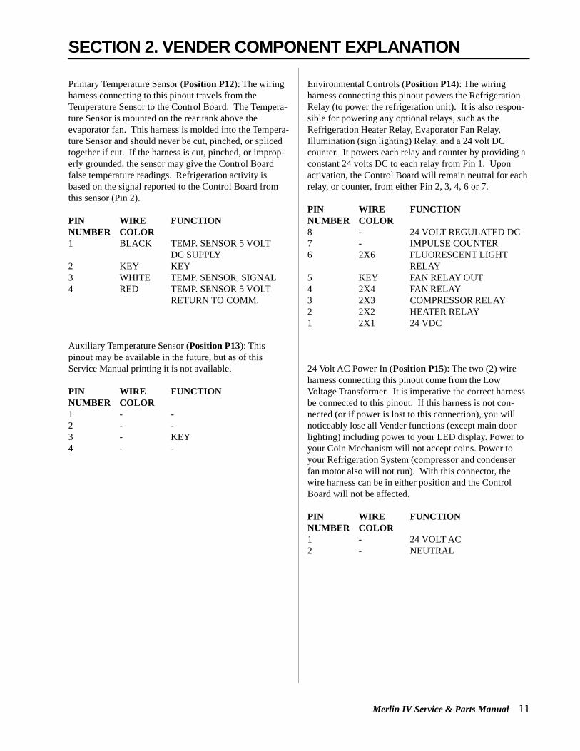
Primary Temperature Sensor (Position P12): The wiringharness connecting to this pinout travels from theTemperature Sensor to the Control Board. The Tempera-ture Sensor is mounted on the rear tank above theevaporator fan. This harness is molded into the Tempera-ture Sensor and should never be cut, pinched, or splicedtogether if cut. If the harness is cut, pinched, or improp-erly grounded, the sensor may give the Control Boardfalse temperature readings. Refrigeration activity isbased on the signal reported to the Control Board fromthis sensor (Pin 2).
PIN WIRE FUNCTIONNUMBER COLOR1 BLACK TEMP. SENSOR 5 VOLT
DC SUPPLY2 KEY KEY3 WHITE TEMP. SENSOR, SIGNAL4 RED TEMP. SENSOR 5 VOLT
RETURN TO COMM.
Auxiliary Temperature Sensor (Position P13): Thispinout may be available in the future, but as of thisService Manual printing it is not available.
PIN WIRE FUNCTIONNUMBER COLOR1 - -2 - -3 - KEY4 - -
Environmental Controls (Position P14): The wiringharness connecting this pinout powers the RefrigerationRelay (to power the refrigeration unit). It is also respon-sible for powering any optional relays, such as theRefrigeration Heater Relay, Evaporator Fan Relay,Illumination (sign lighting) Relay, and a 24 volt DCcounter. It powers each relay and counter by providing aconstant 24 volts DC to each relay from Pin 1. Uponactivation, the Control Board will remain neutral for eachrelay, or counter, from either Pin 2, 3, 4, 6 or 7.
PIN WIRE FUNCTIONNUMBER COLOR8 - 24 VOLT REGULATED DC7 - IMPULSE COUNTER6 2X6 FLUORESCENT LIGHT
RELAY5 KEY FAN RELAY OUT4 2X4 FAN RELAY3 2X3 COMPRESSOR RELAY2 2X2 HEATER RELAY1 2X1 24 VDC
24 Volt AC Power In (Position P15): The two (2) wireharness connecting this pinout come from the LowVoltage Transformer. It is imperative the correct harnessbe connected to this pinout. If this harness is not con-nected (or if power is lost to this connection), you willnoticeably lose all Vender functions (except main doorlighting) including power to your LED display. Power toyour Coin Mechanism will not accept coins. Power toyour Refrigeration System (compressor and condenserfan motor also will not run). With this connector, thewire harness can be in either position and the ControlBoard will not be affected.
PIN WIRE FUNCTIONNUMBER COLOR1 - 24 VOLT AC2 - NEUTRAL
SECTION 2. VENDER COMPONENT EXPLANATION

12 Merlin IV Service & Parts Manual
Low VoltageTransformer(Run 1476 and after will have a fusebetween the transformer and theControl Board)
The MERLIN IV Vender uses a low voltage (75 VA)transformer which reduces 110 volts AC (conventionalvoltage) to 24 volts AC, to power the Vender’s ControlBoard. The transformer is a major contributor to theVender’s operation. Without the transformer, the ControlBoard cannot function.
LOCATION OF TRANSFORMER: In a CDC (CenterDoor Changer) Vender, the transformer is located belowthe Control Board. The fuse is fastened to the ChangerPlug Bracket. In a non-CDC Vender, the transformer andfuse are located at the top of the main door.
OPERATION: The transformer has a three (3) ampexternal fuse on a secondary circuit to protect the ControlBoard and the Coin Mechanism. If the transformer fuseblows, you will lose power to the Control Board, notice-ably losing power to the LED Display, and also losingpower to the Coin Mechanism (Coin Mechanism will notaccept coins and Bill Validator will not accept a bill). Ifyou have a problem similar to this, follow the procedureslisted below.
OPERATION REQUIREMENTS: The transformeroperates by receiving 110 volts AC from the Vender(black and red wires). It transforms the 110 volts AC into24 volts AC which is what the Control Board requires forits operation.
CHECK THE TRANSFORMER AND FUSE: If uponarriving at a Vender, the LED display is not lit and thecoin changer does not take coins or payout coins, makesure the Vender is plugged in. Next check thetransformer’s external fuse for visual damage. Check forcontinuity across the fuse with a voltage meter or similardevice. If defective, replace the external fuse.
Note: Merlin IV Venders made before run 1476 use aninternal fuse in the transformer.
1. Check the power going into the transformer at theconnected red and black wires. It should register 110volts AC. If not, you need to check all wiringleading up to this point from the bottom of theVender’s main door. The transformer may not be theproblem. You may have a broken wire or a badconnection.
2. If 110 volts is registered during Step 1, you want tomeasure voltage at the other end of the transformer.The two (2) pin connector at the Control Boardconnected to position P15 should register approxi-mately 24 volts AC at this end of the harness. If so,check the Control Board; the transformer is good.
3. If 110 volts is registered during Step 1 and 24 voltsAC is not registered during Step 2, you probablyhave a bad transformer. Unplug the Vender andtransformer connections at the transformer (110 voltside). Unplug the transformer from the ControlBoard and remove it from the Vender’s main door bylocating the side of the transformer that has two (2)“built-in” wires going into the plastic housing.
4. Test the sensor by hitting the center of the deliverychute while watching the Control Board’s SensorAdjustment Indicator Lamp. The light should blinksolidly upon impact.
SECTION 2. VENDER COMPONENT EXPLANATION

Merlin IV Service & Parts Manual 13
SECTION 2. VENDER COMPONENT EXPLANATION
Delivery ChuteSensor(Adjustment)
ADJUSTMENT: Located below the Sensor Connector isthe Sensor Adjustment Trimpot, which includes anadjustment screw. The trimpot is used to adjust and finetune the sensor. It is capable of turning both clockwiseand counter-clockwise. Located directly above thetrimpot is the Sensor Adjustment LED Indicator Light.The indicator light is mainly used to aid in adjusting thesensor but can also be used to test its operation duringproduct impact.
1. Turn the adjustment screw clockwise until theindicator light comes on.
2. Turn the screw counter-clockwise until the light justgoes out.
3. Continue to turn the screw counter-clockwise oneturn. Note: Slight adjustments may be neededoutside the factory set one turn. Turning theadjustment screw clockwise makes the sensor moresensitive and counter clockwise makes it lesssensitive. Test vend after every 1/4 turn.
For Multiple Vending from all columns, make sure thesensor is adjusted to the Factory specifications as listedabove. Next, turn the adjustment screw clockwise 1/4turn to increase sensitivity. Test vend 7-12 columns,watch light on the board for a good on and off flash. Ifstill Multiple Vending, turn the adjustment screw anadditional 1/4 turn clockwise until proper adjustment ismade.
For Dry Vending from all columns, make sure the sensoris adjusted to the Factory specifications as listed above.Next, turn the adjustment screw counter-clockwise 1/4turn to decrease sensitivity. Test vend all columns. Ifstill Dry Vending, turn the adjustment screw an additional1/4 turn counter-clockwise until proper adjustment ismade.
TESTING THE DELIVERY CHUTE SENSOR: Makesure the Vender is plugged in and the Controller haspower (the LED display on the front of the Vender will belit and the Coin Mechanism will accept coins). TheSensor Indicator Lamp will blink upon impact on thedelivery chute. Lightly tap the chute with a tool, or your
fist, to simulate a can drop.
1. Locate the Sensor Adjustment Indicator Lamp on thelower right corner of the Vender’s Control Board.Under normal conditions (as in stand-by), the lampshould be off.
2. Test the sensor by vending from column 7 and 12while watching the Control Board’s Sensor Adjust-ment Indicator Lamp. The light should blink solidlyupon impact. If not, turn the sensor adjustmentscrew clockwise in 1/4 turn increments (to increasethe sensitivity) and test after each turn. If theindicator lamp still does not light, turn the adjust-ment screw clockwise for many turns. If the indica-tor lamp does not light, change the sensor (assumingthe Control Board has power and is working).
3. If the Sensor Adjustment Indicator Lamp lightsproperly during Step 2, change the Control Board.

14 Merlin IV Service & Parts Manual
Refrigeration SystemYour Vender’s Refrigeration System comes as a com-pletely sealed unit and should never be cut or tapped intoor the warranty will be voided.
IDENTIFICATION: The refrigeration unit is responsiblefor the cooling of your sealed cabinet and the productsloaded within it. The refrigeration unit’s base plate(compressor, condenser coils and condenser fan motor),are mounted in the bottom (warm) section of the Vender’scabinet. The heat exchange or suction line extends intothe upper (cold) section of the Vender’s cabinet, wherethe evaporator coil is mounted in front of the evaporatorfan motor.
OPERATION REQUIREMENTS:The Refrigeration System requires 110 volts AC from themain wiring harness for it to operate. The main wiringharness will get its voltage for the unit from the Refrig-eration Relay (electronic control) or from the thermostat(conventional control).
OPERATION: The rising temperature in the coolingcompartment is reported to the Control Board from theTemperature Sensor. (See Figure 2.3) The ControlBoard registers the current temperature inside theVender’s cabinet. When it rises equal to, or above thepre-programmed cut-in temperature, the Control Boardwill then complete the circuit to the Refrigeration Relayto energize its coil (shown in Fig. 2.3 as CR-1). TheRefrigeration Relay Coil energizes and closes the contactbetween the common and normally open positions(shown in Fig. 2.3 as CR1-1). This allows power (110VAC) to travel through the Refrigeration Relay Switchand to the main wiring harness. The main wiring harnesswill power the unit immediately.
When the Compressor is powered, it circulates refrigerantthroughout the system by pulling low pressure refrigerantvapor from the Evaporator Coil through the suction lineinto the Compressor. The Compressor compresses it, andforces it through the discharge line into the CondenserCoil.
The Condenser, aided by the Condenser Fan Motor,removes heat from the refrigerant as it flows through theCondenser Coil and releases it to the outside environ-ment. The dropping of the refrigerant temperaturechanges the vapor to liquid.
The Evaporator Coil allows the liquid refrigerant toabsorb heat from the cooling compartment as it evapo-rates in the coil. The falling temperature in the coolingcompartment is caused by the continual circulation ofrefrigerant through the system, removing heat from thecooling compartment, and transporting it to the outsideenvironment.
As the temperature drops, the temperature sensor reportsthis to the Vender’s Main Control Board. When thetemperature drops below the preset cut-out temperature,the Control Board will disable the Refrigeration Relay.This will break the Refrigeration Relay Switch connec-tion (shown in Fig. 2.3 as CR1-1), thus canceling powerto the refrigeration unit.
REFRIGERATION COMPONENTS: The RefrigerationSystem is a sealed system. Cutting or tapping into it willvoid all the manufacturer’s warranty. Described in thissection are explanations of the Refrigeration System’smajor components.
Cooling Compartment - The Cooling Compartment is thesealed area of the Vender holding the product for deliv-ery. This area is designed to allow free flowing air tocirculate throughout the product.
Compressor - The Compressor is a hermetically sealedunit located beneath (outside) the cooling compartment.The Compressor is a pump, driven by the Compressormotor which draws low pressure vapor (refrigerant) fromthe Evaporator Coil, compresses it, and forces it into theCondenser under high pressure. The motor is started andcontrolled by the temperature control.
Condenser - The Condenser is located beneath (outside)the cooling compartment next to the Compressor (it canbe seen from the front with the door open). The Con-denser removes heat from the high pressure vapordischarged from the Compressor and condenses it to ahigh pressure liquid. The Condenser and EvaporatorCoils have aluminum fins attached to effectively increaseheat exchange surfaces.
Starting Relay - The Starting Relay is mounted on theside of the Compressor Housing. The Compressor Motorhas two windings: a start and a run winding. To give themotor torque when it first starts, the Starting RelaySwitches in the additional start winding. After the motorgets up to speed, the relay opens the start winding and themotor continues using only the run winding.
SECTION 2. VENDER COMPONENT EXPLANATION

Merlin IV Service & Parts Manual 15
Thermal Overload - The Thermal Overload is a heatsensitive device mounted on the side of the CompressorHousing. If the Compressor Motor gets too hot, or drawsan excessive amount of current, the Thermal Overloadwill open, breaking the circuit to the Compressor. Afterthe Compressor cools to a safe operating temperature, theThermal Overload will close allowing the Compressorand Condenser fan motors to restart.Condenser Fan and Motor - The Condenser Fan andMotor, located beneath the cooling department, are aforced air device using outside ambient air to cool thesurface of the Condenser Coil. The Condenser Fan andMotor run while the Compressor operates.
Evaporator Coil - The Evaporator Coil is located in thecooling compartment. As low pressure liquid passesthrough the Evaporator Coil, it absorbs and removes heatfrom the compartment as it changes to vapor. TheCondenser and Evaporator Coil have aluminum finsattached to effectively increase their heat exchangesurfaces.
Evaporator Fan and Motor - The Evaporator Fan andMotor are a forced air device circulating air throughoutthe cooling compartment and over the heat exchangesurface of the Evaporator Coil. The Evaporator Fan andMotor run continually.
Capillary Tube - The Capillary Tube is located in therefrigerant line, between the Condenser and EvaporatorCoil. The small diameter tube is used as a meteringdevice to control the flow of liquid refrigerant to theEvaporator Coil. This creates low pressure causing therefrigerant to vaporize and absorb heat as itpasses through the Evaporator Coil.
Drier - The Drier is located in the refrigerantline between the Capillary Tube and Con-denser. It traps and removes moisture fromthe Refrigeration System while allowing oiland refrigerant to pass through the system.
Accumulator - The Accumulator is located inthe refrigerant line between the EvaporatorCoil and Compressor. The Accumulator trapsany liquid refrigerant which did not vaporizebefore it reached the Compressor.
Refrigeration Relay - The Refrigeration Relayis located in the lower section of the Vender’scabinet near the main wiring harness. It takes
the place of the Temperature Control (thermostat) usedover the past several years in “electro-mechanical”Venders. The Refrigeration Relay is responsible forpowering the Compressor and Condenser Fan Motors.The Refrigeration Relay consists of a coil powered by theControl Board (24 volts DC) and a double-pole switch.When the Control Board completes the circuit to theRefrigeration Relay, the Relay will energize, closing thecontact between the common and the normally openpositions. When this happens, power (110 volts) travelsfrom the Refrigeration Relay to the main wiring harnessfor the refrigeration unit.
REFRIGERATION CYCLE:
1. The rising temperature in the cooling compartment isreported to the Control Board through the Tempera-ture Sensor.
2. The Control Board registers the current temperatureinside the Vender’s cabinet. When it rises equal to,or above the pre-programmed cut-in temperature, theControl Board will complete the circuit to theRefrigeration Relay to energize its coil.
3. The Refrigeration Relay coil closes the contactbetween the common and normally open positionsallowing 110 volts to travel to the main wiringharness to start the Compressor.
Figure 2.3
SECTION 2. VENDER COMPONENT EXPLANATION
Main Wiring Harnesscircuits for evap. fan motorand door power eliminatedfor clarity
Refrigeration Relay
to wall outletBlack (110 VAC)White (neutral)Ground
Control Board
Temperature Sensor
CR1-1
CR1-2(not used)
to compressor &condenser fan motor
24 VDC
neutral
POWER FLOW TO REFRIGERATION SYSTEM

16 Merlin IV Service & Parts Manual
4. The Compressor circulates refrigerant throughout thesystem by pulling low pressure refrigerant vaporfrom the Evaporator Coil, compressing it, andforcing it into the Condenser. The Condenser, aidedby the Condenser Fan Motor, removes heat from therefrigerant as it flows through the Condenser andreleases it to the outside environment. The droppingof the refrigerant temperature changes the vapor toliquid.
5. The Evaporator Coil allows the liquid refrigerant toabsorb heat from the cooling compartment as itevaporates in the coil.
6. The falling temperature in the cooling compartmentis caused by the continual circulation of refrigerantthrough the system, removing heat from the coolingcompartment and transporting it to the outsideenvironment. When the temperature drops, theTemperature Sensor reports this to the Vender’sControl Board.
7. When the temperature drops below the preset cut-outtemperature, the Control Board will disable theRefrigeration Relay, thus killing power to therefrigeration unit.
TESTING THE REFRIGERATION SYSTEM:
1. The sealed refrigeration unit can be tested byunplugging it from the top of the main wiring harnessand plugging it directly into a power source. If theunit still does not operate, a problem exists within thesealed unit.
2. If the sealed refrigeration unit runs when pluggedinto an external power source, the problem more thanlikely lies between the Control Board, the Refrigera-tion Relay, and the main wiring harness. Fortroubleshooting this circuit, refer to Section 6,Vender Maintenance: Troubleshooting RefrigerationProblems.
SECTION 2. VENDER COMPONENT EXPLANATION
Figure 2.4
Accumulator
Evaporator
Condenser
Compressor
Capillary
Low pressure gas
Low pressure gas
Changing from high to low pressure liquid
Liquid changing to a gas
Discharge line
Filter/Drier
Gas changing
to liquid
REFRIGERATION SYSTEM FLOW CHART
Suction line
High pressure gas

Merlin IV Service & Parts Manual 17
Vender ProgrammingTHE NECESSITY OFCORRECT PROGRAMMINGYour MERLIN IV Vender must be programmed correctlyfor it to operate properly. There are other modes thatmay not interfere with normal operation of the Vender; oryou may not notice the abnormal operation (if they arenot programmed properly). As a whole, improperprogramming could cause the following problems:
MODE PROBLEM SEEN
Pric Wrong prices, even free vending
StoS Columns not vending or wrong columnsvending
Con Vender options such as forced vend/escrownot working properly
SdEP Vender multiple vending or “long” vendcycles
StCL If enabled with use of timer or key switchwill disable selections
tinE Will disable selections or RefrigerationSystem if turned on
FriG Will keep the unit from running or allowwarmer/colder temperatures
PAS Will keep you from accessing the externalpassword mode
LAnG Will display different languages for displaymessages
PRECAUTIONS TO TAKE WHENWORKING WITH CONTROL BOARDAs with any printed circuit board, our electronics are verysensitive to Electrostatic Discharge (ESD). Simplywalking across a tile, or carpeted floor, can generate arange of 30,000 to 50,000 volts of electricity. One ESDcan be enough to seriously damage your Control Board;or at least weaken it enough that “erratic problems” couldoccur in the future. Even a discharge surge under 100 or200 volts is enough to create shorts, or problems, withinthe circuitry of the electronics. It is advised when storingthe electronics that they be kept in their anti-static bags,even if the electronics are thought to be defective. If aControl Board is thought to be defective and is really not,it soon will be after being charged with ESD. The idealprevention against ESD is to use anti-static conductivewrist straps which ground you to the machine before
touching the electronic boards. If it is not possible to usethese, at least ground yourself before handling theelectronic boards. Whatever method you use, alwayshandle the electronic boards by the edges. Be careful notto touch the components on the Control Board.
INTRODUCTION TO PROGRAMMINGAs mentioned earlier in “The Necessity Of CorrectProgramming,” it is very important your Vender isprogrammed properly. To do this, you must understandhow the system works and what it takes to program yourVender. As you will see, after you are able to programone or two modes, you will be able to use similarprocedures to program all modes.
MANEUVERING THROUGH LEVELS - The first stepto understanding MERLIN IV programming is to learnhow to negotiate through and around the menu levels toaccomplish your task. To maneuver through the menulevels you must use the select buttons on the front of yourVender. Certain buttons have different meanings. Youwill use these buttons to move “up” or “down” throughthe menus. You will also use certain buttons to enter ontoa new menu level or to home back to a previous level.These four (4) meanings that we have just mentioned arelisted below, along with the active button for each.NOTE: Programming Flowchart located in rear of manual
BUTTON MEANING FUNCTION1 UP Increase, Next, Etc.2 DOWN Decrease, Previous,
Etc.3 ENTER Save, Accept, OK, Etc.
[press and release,less than two (2)seconds]
3 HOME Exit, Escape, Return,[press & hold Etc.for two (2) secondsor greater]
MENU SYSTEM - When programming, you must first usethe three programming buttons listed above to maneuverthrough menus and sub-menus before you will be allowedto accomplish your task. Each menu consists of variousitems, or modes, such as the “Pric” Mode (Selection PriceSetting Mode) or the “StoS” Mode (Space to SalesSetting Mode). There are currently two different mainmenus available.1. INTERNAL (Service) MENU: This menu is available
only with the Vender’s main door open. It is accessedupon pressing the Control Board’s mode button.
SECTION 3. VENDER PROGRAMMING
18 Merlin IV Service & Parts Manual
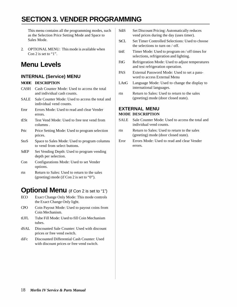
This menu contains all the programming modes, suchas the Selection Price Setting Mode and Space toSales Mode.
2. OPTIONAL MENU: This mode is available whenCon 2 is set to “1”.
Menu LevelsINTERNAL (Service) MENUMODE DESCRIPTIONCASH Cash Counter Mode: Used to access the total
and individual cash counts.SALE Sale Counter Mode: Used to access the total and
individual vend counts.Eror Errors Mode: Used to read and clear Vender
errors.tESt Test Vend Mode: Used to free test vend from
columns .Pric Price Setting Mode: Used to program selection
prices.StoS Space to Sales Mode: Used to program columns
to vend from select buttons.SdEP Set Vending Depth: Used to program vending
depth per selection.Con Configurations Mode: Used to set Vender
options.rtn Return to Sales: Used to return to the sales
(greeting) mode (if Con 2 is set to “0”).
Optional Menu (if Con 2 is set to “1”)ECO Exact Change Only Mode: This mode controls
the Exact Change Only light.CPO Coin Payout Mode: Used to payout coins from
Coin Mechanism.tUFL Tube Fill Mode: Used to fill Coin Mechanism
tubes.dSAL Discounted Sale Counter: Used with discount
prices or free vend switch.diFc Discounted Differential Cash Counter: Used
with discount prices or free vend switch.
SdiS Set Discount Pricing: Automatically reducesvend prices during the day (uses timer).
StCL Set Timer Controlled Selections: Used to choosethe selections to turn on / off.
tinE Timer Mode: Used to program on / off times forselections, refrigeration and lighting.
FriG Refrigeration Mode: Used to adjust temperaturesand test refrigeration operation.
PAS External Password Mode: Used to set a pass-word to access External Menu
LAnG Language Mode: Used to change the display tointernational languages.
rtn Return to Sales: Used to return to the sales(greeting) mode (door closed state).
EXTERNAL MENUMODE DESCRIPTIONSALE Sale Counter Mode: Used to access the total and
individual vend counts.rtn Return to Sales: Used to return to the sales
(greeting) mode (door closed state).Eror Errors Mode: Used to read and clear Vender
errors.
SECTION 3. VENDER PROGRAMMING

Merlin IV Service & Parts Manual 19
Internal MenuOpening the Vender’s main door and pressing the ControlBoard’s mode button will allow you to access the InternalMenu. This section completely outlines all the InternalMenus, including descriptions and operation instructionsfor each mode. After five (5) minutes without activity, theControl Board will revert to the Sales Mode (the LEDwill show the greeting).
Note: The following menu order pertains to 67100-7and higher control board.
Cash Counter Mode (CASH)This mode allows you to manually extract
the amount of cash taken into the Vender through productsales (up to $999,999.99). The Cash Counter Modeconsists of a total count which is non-resettable. Indi-vidual selection counts are resettable, depending upon theproper configuration setting (see Configurations). Thecounts will be preceded by the count type (CL=cashlevel) and can be displayed in one (1) or two (2) sets offour (4) digits. Examples for both types of cash countersare:
Count Type Actual Count 1st Display 2nd Display 3rd Display
Total Cash $56,789.10 “CASH” “567” “89.10”Count
Selection $6,789.10 “CL [number]” “67” “89.10”Cash Count
OPERATION: If <enter> is pressed when the displayshows “CASH”, the Controller will enter the CashCounter Mode. The display will flash “CASH” and thetotal amount of cash taken into the Vender. This can beshown in two (2) sets of four (4) digits (see Example 1above). Using <up> or <down> will cycle throughindividual selection cash counts for each. The displaywill flash individual selection counts (as shown inExample 2 above). If <home> is pressed anytime duringthis operation, the Controller will return to the “CASH”display. From “CASH” pressing <down> will take you to“rtn”. Pressing <up> will take you to “SALE”.
CLEARING INDIVIDUAL COUNTERS: If the Con-figurations Mode is set to allow the individual counters tobe reset, the individual counters will reset upon reading atleast one of them and closing the Vender’s main door(actuating the Vender’s door switch).
Sale Counter Mode (SALE)This mode is very similar to the Cash
Counter Mode. The Sale Counter Mode allows you tomanually extract the amount of product vended from yourVender (up to 99,999,999 vends). The Sale Counter Modeconsists of a non-resettable total count and individualselection counts which are resettable, depending uponthe proper configuration setting (see Configurations).The counts will be preceded by the count type (SL=salelevel) and can be displayed in one (1) or two (2) sets offour (4) digits. Examples for both types of sale countersare:
Count Type Actual Count 1st Display 2nd Display 3rdDisplayTotal Sale 5,678,910 “SALE” “567” “8910”Count
Selection 678,910 “SL [number]” “67” “8910”Sale Count
OPERATION: If <enter> is pressed when the displayshows “SALE”, the Control Board will enter the SalesCounter Mode. The display will flash “SALE” and thetotal amount of sales made by the Vender. This can beshown in two (2) sets of four (4) digits (see Example 1above). Using <up> or <down> will cycle throughindividual selection sale counts. The display will flashindividual selection counts (as shown in Example 2above). If <home> is pressed anytime during thisoperation, the Controller will return to the “SALE”display. From “SALE” pressing <down> will take you to“CASH” . Pressing <up> will take you to “Eror”.
CLEARING INDIVIDUAL COUNTERS: If the Configura-tions Mode is set to allow the individual counters to bereset, the individual counters will reset upon reading atleast one of them and closing the Vender’s main door(actuating the Vender’s door switch).
Errors Mode (Eror)This mode was designed to help diagnose
Vender problems. Upon opening the Vender’s main door,the LED will flash any possible errors. (For a list, refer toSection 6, Vender Maintenance: Error Codes.) If there areno errors, the display will flash “none” and after five (5)minutes of no activity will revert to the sales greeting (ICECOLD). The Errors Mode was designed to give a detaileddescription of each error and allow you to clear errors.
SECTION 3. VENDER PROGRAMMING
CASH
SALE
Eror

20 Merlin IV Service & Parts Manual
displayed on the LED display during the greeting. If theconfigurations are set to allow multiple pricing (perselection), the display will not show the vend price duringthe greeting unless all selections are set to the same price.You will have two options when setting prices:
• Multiple Pricing – “ALL” Pricing – Gives you theoption to set one price for all selections.
• Individual Pricing – Allows you to set a differentvend price for each selection.
If a free vend key switch is in use (turned-on), the displaywill scroll “FREE” during the greeting instead of thenormal vend price.(That is, if all selections are assignedin StCL mode.)OPERATION: If <enter> is pressed when the displayshows “PriC”, the Controller will enter the price settingmode.• Single Price Operation: The display will flash “SPri”
and the current single price setting. This will be thesingle price viewing level. If <enter> is pressedagain, the display will show the current single priceonly. If <up> is pressed or held, the price willincrease in .05 increments. If <down> is pressed orheld, the price will decrease in .05 increments. Afterthe desired price has been set, press <home> to saveyour setting and return to the single price viewinglevel. Pressing <home> from the single price viewinglevel will return you to the display of “PriC”.
• Multiple Price Operation: The display will flash“ALL” followed by the last price set for all selec-tions. If <enter> is pressed at this point, the displaywill steadily show the current “ALL” price. If <up> ispressed or held, the price will increase in .05 incre-ments. If <down> is pressed or held, the price willdecrease in .05 increments. After the desired pricehas been set, press <home> to save your setting andreturn to where the display flashes “ALL” followedby the new “ALL” price. You may now set a few, all,or different individual prices if desired.
• Individual Pricing: If <up> or <down> is pressedwhen the display flashes “ALL” followed by thecurrent majority price setting, the display will cyclethrough the individual price settings for eachselection. The display will flash the selectionnumber followed by the price for that selection.Example: If selection one is set at fifty cents, thedisplay will flash “P 1” followed by “.50”. Pressing<enter> while a individual selection is being dis-played will cause the display to steadily show the
OPERATION: If <enter> is pressed when the displayshows “Eror”, the Controller will enter into the errorsdescriptive display mode. At this point, the display willshow any and all current Vender errors followed by thedescriptive errors for each. If no errors exist, “none” willappear on the display but will revert back to the salesgreeting after five (5) minutes of no activity. If <home> ispressed anytime during this operation, the Controller willreturn to the “Eror” display. From “Eror” pressing<down> will take you to “SALE” and pressing <up> willtake you to “tESt”.
CLEARING ERRORS: To clear an error, wait until the errorto be cleared is shown on the LED display. Then immedi-ately press the <up> or <down> button and hold it in for atleast two (2) seconds and the error will disappear. Followthis procedure for each error.
Column Test Vend Mode (tESt)This mode is used to vend test by
column, not by selection. After entering into this mode,you will have to pick the column which is desired to betested. By pressing the <enter> button, the ControlBoard will vend from that column. No money is needed.This mode will test the Control Board’s ability to distrib-ute 24 volts DC to the proper vend motor upon command.It will also test the mechanical part of the vending circuit,such as the vend motor and rotor. It does not test theControl Board’s coin acceptance/credit/payout circuit.OPERATION: If <enter> is pressed when the displayshows “tESt” the Controller will enter the Column VendTest Mode. The display will show “CO 1” (Column 1).Using <up> or <down> will cycle you through all theavailable columns to be test vended (the display mayshow some columns that are not in your Vender; nothingwill happen if a test vend is attempted from these col-umns.). If <enter> is pressed, the Controller will attemptto test vend from the column which is being displayed. Ifa vend is not in progress, pressing <home> will returnyou to the “tESt” display. From “tESt”, pressing <down>will take you to “Eror”. Pressing <up> will take you to“PriC”.
Note: Test vends will not affect cash or sale counters.
Selection Price Mode (PriC)This mode is used to set vend prices.
Depending on the Configurations Mode (discussed laterin this Section), this mode will allow you to set eithersingle or multi-pricing. When the configurations are setto allow single pricing, only one price has to be set in the“PriC” Mode (not individually). The current price will be
SECTION 3. VENDER PROGRAMMING
tESt
PriC

Merlin IV Service & Parts Manual 21
vend price for that selection to allow a change to theprice. Press <up> to increase the price value in .05increments or <down> to lower it in .05 increments.After the desired price has been set, press <home> tosave your setting and return to where the displayflashes “P X” followed by the new selection price.From “PriC”, pressing <down> will take you to “tESt”.Pressing <up> will take you to “StoS”.
Space to Sales Mode (StoS)This mode is a very important part of
programming. It will determine what column will vendupon pressing a particular select button. You will use thismode to program column assignments by assigning acolumn (or columns) to each selection button that youdesire to use. You may also decrease the number of theVender selections. Example: Your Vender has a total often (10) select buttons on the front panel. If you wish,you may program the controller to only use eight (8),seven (7), or six (6) selections (or even less). This is doneby assigning all additional columns to one of the popularselections being used. A benefit of doing this is you willbe allowed to allocate the “extra” columns to a “fastermoving” flavor. Space to Sales Mode will come factoryset for your type of Vender. Upon entering the Space toSales Mode two different types of settings are available:
• Factory Standard Space To Sales: There are eight (8)factory preset settings from which to choose. Thesesettings depend on how the “Con 12” Mode is set(for 12 or 10 columns, see Appendix A in the rear ofthe Manual).
• Custom Space To Sales: Allows you to customconfigure any column to any selection
OPERATION: If <enter> is pressed when the displayshows “StoS”, the Controller will enter the Space to SalesSetting Mode. The Control Board will always enter at thecurrent Space to Sales Setting. If your Vender is pro-grammed for custom Space to Sales, or if programmedwith a Hand Held Computer, you will enter at “CStS”. If<up> or <down> is pressed at this point, you will beallowed to cycle through all Space to Sales Settings.
• Factory Standard Space To Sales: Pressing <enter>at any Factory Standard (“Opt”) Setting will “lockin,” or reprogram, the Control Board for that particu-lar Space to Sales Setting. Upon doing this, thedisplay will automatically start sequencing througheach selection followed by all the columns that areassigned to each (see Example below). After each
selection has been shown, the display will return to“StoS”.
Example: If after entering a Factory StandardSetting the display flashes “SL 1”, and then flashes“1”, then flashes “2”, selection one has beenassigned to Columns 1 and 2 only. This will occurfor each selection.
• Custom Space To Sales: Pressing <enter> at “CStS”will allow you to enter the Custom Space To SalesMode. Upon entering this mode, the display willalways start by flashing “SL 1” (Selection 1) followedby flashing each column number assigned to thisselection. Example: The display flashes “SL 1”, thenflashes “1”, and then flashes “2”. Selection 1 hasColumns 1 and 2 assigned to it only. Pressing <up>or <down> at this point allows you to cycle throughSelections 1 through 12, with each selection showingthe columns assigned to it. If <enter> is pressed at aselection, the display will show “Co 1”. This standsfor Column 1 for that particular selection. Pressing<up> or <down> at this point will allow you to cyclethrough Columns 1 through 10 for the selectionentered. If any column is flashing, this means it isassigned to the selection. If a column is not flash-ing, then it is not assigned to the selection. Pressing<enter> will change a column’s flashing condition.This allows you to assign or un-assign columns. Ifno changes are made, pressing <home> will returnyou to the Space to Sales Setting list at “CStS”. If achange to a selection is made, pressing <home> willreturn you to the selection level where the displayflashes the selection number followed by thecolumns assigned to that selection. Follow this sameprocedure for all selections that you wish to program.
Important Note: Anything done in this mode willoverride any previously assigned Factory Standardor Custom Settings.
When completely finished in Custom Space to SalesMode, pressing <home> will return you to “StoS” display.From “StoS” pressing <down> will take you to “PriC”.Pressing <up> will take you to “SdEP”.
Set Vending Depth Mode(SdEP)
Since the vend motors on a MERLIN IV Vender do nothave cams or switches, programming electronically thevending depth is extremely necessary. With older styleElectro-Mechanical Venders, it was necessary to adjust
SECTION 3. VENDER PROGRAMMING
StoS
SdEP

22 Merlin IV Service & Parts Manual
the vend timing cam by either filling notches or rotatingpart of the cam to change the vending depth from triple ordouble to single depth. With the MERLIN IV Vender, youhave a choice of either single or double depth for eachselection and not by column. It is necessary to programthe correct depth for each selection to prevent multiple orslow vends. For instance, if your actual vending depth istwo and you program this selection for single depth, itwill double vend every time.
OPERATION: If <enter> is pressed when the displayshows “SdEP”, the Controller will enter the Set VendingDepth Setting Mode. The display will show “ALL”.From this point, two types of settings are available: the“All” depth setting enables you to set all depths the same(such as “ALL” of the price mode) and “Individual”depth setting gives you the option to set all depthsindividually for each selection.
• “ALL” Setting: If <enter> is pressed when thedisplay shows “ALL”, the Controller will enter theDepth Setting Mode for “ALL” selections. Thedisplay will steadily show “ALL” and flash thecurrent depth setting. Pressing <up> or <down>allows you to change the flashing depth settingbetween 1 or 2. Pressing <enter> will save changesand return you to where the display will show “ALL”.At this time, you will be able to cycle through eachindividual depth setting. Pressing <home> from thislevel will return you to the “SdEP” display.
Note: If you have selection depth settings that aredifferent, but a majority of the settings are the same,it is advised to set the majority setting from withinthe “ALL” setting first. You will then be able toprogram the few settings that are individuallydifferent. This will cut down on program time.
• Individual Setting: If <up> or <down> is pressed whenthe display shows “ALL”, the Controller will cyclethrough each individual setting showing the selec-tion number and the current setting. If <enter> ispressed while the display is showing an individualdepth setting, the current setting starts flashing.Pressing <up> or <down> allows you to change theflashing depth setting between 1 or 2. Pressing<home> locks in your setting and returns you to theindividual level at the point where you entered it (atthe setting just changed). At this time, you will beable to cycle through each individual setting.Pressing <home> from the individual level returnsyou to the “SdEP” display. From “SdEP” pressing<down> will take you to “StoS”. Pressing <up> willtake you to “Con”.
Configurations Mode (Con)This mode is used to set Vender options
dealing with pricing, acceptance, payback, and a fewother optional features. While in the ConfigurationsMode, the display will show the configuration followedby the current setting. If the display shows “C 1 0”, thismeans Configuration 1 is currently set to 0. In otherwords, the Vender is set for single pricing. The configura-tions are as follows:CONFIG. # SETTINGSC1 0 = Single Pricing
1 = Multiple PricingC2* 0 = Hide Optional Menu Items
1 = Show Optional Menu ItemsC4 0 = Display errors or “nonE”
1 = Display Sales, Cash Values, andexisting error or “nonE”
C5 0 = No reset of individual counters1 = Allow reset of individual counts upon
reading and door switch actuation
C6 0 = Credit will be returned if properchange cannot be made
1 = Allow vend regardless of changertube levels (change may not be paid)
C7 0 = Will allow bill acceptance regardlessof payout availability
1 = Will only accept a bill if coin tubeshave enough coins to cover thedifference between the bill value andthe maximum vend price
C8 0 = Escrow to vend (will act as a billchanger)
1 = Forced attempt (will not act as a billchanger)
C9 0 = Change is automatically returned tocustomer after a valid vend
1 = Will hold the customer’s change inescrow to allow a multiple purchase
C10 0 = Bill escrow disabled1 = Bill escrow enabled
C11 0 = All errors displayed1 = Certain errors displayed
C12 0 = 12 column mode1 = 10 column mode
SECTION 3. VENDER PROGRAMMING
Con

Merlin IV Service & Parts Manual 23
*Note: C2 - Version 67100-7 and after.
OPERATION: If <enter> is pressed when the displayshows “Con”, the Controller will enter the ConfigurationsMode. The display will show Configuration 1 and itssetting (as listed in the Configurations Description). If<up> or <down> is pressed at this point, the display willcycle through each configuration. Pressing <enter> whilethe display shows a configuration, allows the currentconfiguration setting to start flashing. Pressing <up> or<down> while the current configuration setting is flashing,allows you to toggle the configuration setting between 0and 1. If changes are made to a configuration, pressing<enter> will return you to the Configuration List Leveland save any change. Follow the above process for allconfigurations which you wish to set. When done,pressing <home> will return you to the “Con” display.From “Con”, pressing <down> will take you to “SdEP”.Pressing <up> will take you to “rtn” if C2 is set to “0”, orto “ECO” if C2 is set to “1”.
Return to Sales /Greeting Mode (rtn)
This mode is used to exit the Service Menu and return tothe Sales Mode, where the display flashes the greeting(ICE COLD or PEPSI COLA) along with any other displayoptions.
OPERATION: If <enter> is pressed when the displayshows “rtn”, the Controller will revert to the Sales Modeand the greeting will be displayed. From “rtn”, pressing<down> will take you to “Con”. Pressing <up> will takeyou to “CASH”.
Optional Menu ItemsExact Change Value Mode(ECO)
This mode controls the Exact Change Only light. If themachine cannot make change for the value (or lower)specified in this mode, the Exact Change Only lamp willlight.
Note: 67100-X Board and later versions
OPERATION: If <enter> is pressed when the displayshows “ECO”, the Controller will enter the Exact ChangeValue Setting Mode. The display will show the exactchange value. Pressing <up> or <down> allows you to
adjust the value. Pressing <home> will save the currentlydisplayed value and return you to the “ECO” display.From “ECO”, pressing <down> will take you to “Con”.Pressing <up> will take you to “CPO”.
Coin Payout Mode (CPO)This mode allows you to payout coins
from the Coin Mechanism’s Tubes through the ControlBoard. This mode is mainly used because some types ofcoin mechanisms do not have payout buttons (switches)on them. This can also be used as a test to confirm theControl Board’s ability to payout coins (will payout thesame as after a sale).OPERATION: If <enter> is pressed when the displayshows “CPO”, the Controller will enter the coin payoutmode and display the lowest coin value (.05). Using <up>or <down> will allow the user to cycle through all coinvalues available for payout. If <up> or <down> is pressedand held at this point, a coin of the displayed value willbe paid out. The word “PAY” will be displayed as coinsare paid out. Coins will continue to payout as long as<up> or <down> is held. If <home> is pressed anytimeduring this operation, the Controller will return to the“CPO” display. From “CPO”, pressing <down> will takeyou to “ECO”. Pressing <up> will take you to “tUFL”.
Note: If you are using the “tUFL”, you must use the“CPO” Mode to payout coins.
Coin Tube Fill Mode (tUFL)This mode is used to keep inventory of
the exact coin tube levels as each coin is inserted. Duringthis mode, the LED display will register each coin as it isinserted (in no particular order) and report its value to theVender’s Control Board. The Control Board will in turnremember the Coin Mechanism’s coin tube levels andautomatically deduct a coin each time a coin is paid out(through “CPO” Mode or during a vend.). This mode canonly be used if a Multi-Drop Bus Coin Mechanism is inuse.
OPERATION: If <enter> is pressed when this displayshows “tUFL”, the Controller will enter the Coin Tube FillMode. The LED display will go blank allowing thedeposit of nickels, dimes, or quarters through the coininsert or coin acceptor inlet chute. If <home> is pressedanytime during this operation, the Controller will return tothe “tUFL” display. From “tUFL”, pressing <down> willtake you to “CPO”. Pressing <up> will take you to“dSAL”.
SECTION 3. VENDER PROGRAMMING
rtn
ECO
tUFL
CPO

24 Merlin IV Service & Parts Manual
Note: The use of the Coin Mechanism’s Manual Coinpayout buttons is discouraged to keep from corruptingthe coin counts. As long as the sales greeting is scroll-ing, the manual buttons cannot be used.
Discounted Sale CounterMode (dSAL)
This mode is very similar to the Sale Counter Mode. Itallows you to manually extract the amount of productdispensed through your Vender during the discountedsales periods (up to 99,999,999). The Sale Counter Modeconsists of a non-resettable total count and individualcount per selection which are resettable, depending uponthe proper configuration setting (see Configurations).The counts can be displayed in up to two (2) sets of four(4) digits. Examples for both total and individual countersare:
Discount Actual 1st 2nd 3rdCount Count Display Display DisplayType
Total Sale 5,678,910 “SALE” “567” “8910”Count
Selection 678,910 “SL [number]” “67” “8910”Sale Count
OPERATION: If <enter> is pressed when the displayshows “dSAL”, the Controller will enter the DiscountedSales Counter Mode. The display will flash “SALE” andthe total amount of discounted sales made by the Vender.This can be shown in two (2) sets of four (4) digits (asshown in Example 1 above). Using <up> or <down> willcycle through individual discounted sales counts foreach selection. The display will flash individual counts(as shown in Example 2 above). If <home> is pressedanytime during this operation, the Controller will return tothe “dSAL” display. From “dSAL” pressing <down> willtake you to “tUFL”. Pressing <up> will take you to“diFc”.
CLEARING INDIVIDUAL COUNTERS: If the Configura-tions Mode is set to allow the individual counters to bereset, the individual counters will reset upon reading atleast one (1) of them and closing the Vender’s main dooror actuating the Vender’s door switch.
Differential Cash DiscountedCounter Mode (diFC)
This mode is comparable to the Cash Mode. It allowsyou to monitor the difference between discounted pricesand regular prices. The Differential Cash DiscountedCounter Mode is a non-resettable total count. If productis sold for less than the vend price, the counts will bepreceded by a negative symbol (-). If product is sold forgreater than the vend price, the counts will be shownnormally. Examples for both are:
Differential Actual 1st 2nd 3rdCount Count Display Display DisplayType
Differential -$789.10 “CASH” “-7” “89.10”Cash Count(Negative)
Differential $789.10 “CASH” “7” “89.10”Cash Count(Positive)
OPERATION: If <enter> is pressed when the displayshows “diFC”, the Controller will enter the DifferentialCash Discounted Counter Mode. The display will flash“CASH” and the total difference between regular vendprices and discounted prices (as shown in Example 1above). Pressing <home> anytime during this operationwill allow the Controller to return to the “diFC” display.From “diFc”, pressing <down> will take you to “dSAL”.Pressing <up> will take you to “SdiS”.
CLEARING INDIVIDUAL COUNTERS: This is a nonresettable counter.
Set Discount PricingMode (SdiS)
This mode is used to set discount prices for eachselection. This mode works in conjunction with the built-in timer in the “tinE” Mode. Before entering “tinE” Mode,you must set the selections to “1” in StCL Mode. Afterthe StCL Mode you may set the discounted price for eachdesired selection. Then, set the time you wish thediscounted selection to be activated by using the “dScn”settings in the “tinE” Mode under the day function.
SECTION 3. VENDER PROGRAMMING
SdiS
dSAL
diFc

Merlin IV Service & Parts Manual 25
current “StCL” setting. Pressing <up> or <down>allows you to change the flashing setting between 0and 1. Pressing <enter> saves any change andreturns you to the selection level where the displaysteadily shows “StCL” and the new setting. At thistime you will be able to cycle through each selectionto set individual settings. If completely done,pressing <home> from the selection level (displayshows “ALL and current setting”) will return you tothe “StCL” display.
• Individual Setting: If <up> or <down> is pressed whenthe display shows “ALL and the current setting”, theController will cycle through each selection showingthe selection number and the current setting for thatselection. Example: If the display shows “t 3 1” (forselection 3, the timer is set to on). If <enter> ispressed while the display is showing an individualselection timer setting, the current setting for thatselection will start flashing. Pressing <up> or <down>allows you to change the flashing timer settingbetween 0 and 1. Pressing <enter> saves anychange and returns you to the selection level. Atthis time you will be able to cycle through eachselection to set other individual Timer ControlledSelection Settings. Pressing <home> from theselection level will return you to the “StCL” display.From “StCL”, pressing <down> will take you to“SdiS”. Pressing <up> will take you to “tinE”.
Notes: When pressing a selection in the StCL Mode:
1) Version 67100-3 and after, the LED will display “NoSale till XXXX”(XXXX represents the time set for the timer).
2) Version 67100-2 and prior, the LED will show the“Greeting”, and “Sold Out”.
Time and Timer SettingsMode (tinE)
This mode is used mainly to turn selections, lighting, and/or refrigeration off and back on during predeterminedtimes of the day and days of the week. In the “tinE”Mode, you must set the current year, date, hour and dayof the week for the timer to operate. The “tinE” Mode isalso used to set each “on” and “off” time in which thetimer will operate. Within the “tinE” Mode, there areseveral different functions listed below with a meaningand example for each.
OPERATION: If <enter> is pressed when the displayshows “SdiS”, the Controller will enter the Discount PriceSetting Mode. The display will flash “ALL” (for allselections) and flash the last discount price value that“ALL” was set at. This is referred to as the selectionlevel. If <enter> is pressed at this point, the display willsteadily show the discount value for all selections. Press<up> to increase the discount price value in .05 incre-ments or <down> to lower it in .05 increments. If<home> is pressed after adjusting the price, your newdiscount price will be saved and the display will return tothe selection level. You may now set a few, all, ordifferent individual discount prices if desired. If <up> or<down> is pressed when the display flashes “ALL” (for allselections) then flashes the last discount price value that“ALL” was set at, the display will cycle through theindividual discount price settings for each selection. Thedisplay will show the selection number followed by thediscount price for that selection. Example: If selectionone is set at fifty cents, the display will flash “P 1”followed by “.50”. Pressing <enter> while an individualselection is being displayed will cause the display tosteadily show the discounted vend price for that selec-tion to allow a change to it. Press <up> to increase thediscount price value in the same fashion as above or<down> to lower it. Pressing <home> after adjusting aprice will save that price and return you to the selectionlevel. Pressing <home> while at the selection level willreturn you to the “SdiS” display. From “SdiS”, pressing<down> will take you to “diFc”. Pressing <up> will takeyou to “StCL”.
Set Timer ControlledSelections Mode (StCL)
This mode is used to choose the selections to turn offeither using the built-in timer or with the optional keyswitch kit. This mode must be set to enable one or all ofthe selections for the timer or the key switch to operate.The timer or key switch will control any selections set to“1”. Selections set to “0” will function normally.OPERATION: If <enter> is pressed when the displayshows “StCL”, the Control Board will enter the Set TimerControlled Selections Mode at the selection level and thedisplay will show “ALL”. From this point, two types ofsettings are possible:
• “ALL” Setting: If <enter> is pressed when thedisplay shows “ALL and the current setting”, theControl Board will enter the “ALL” Setting Mode.The display will steadily show “ALL” and flash the
SECTION 3. VENDER PROGRAMMING
StCL
tinE
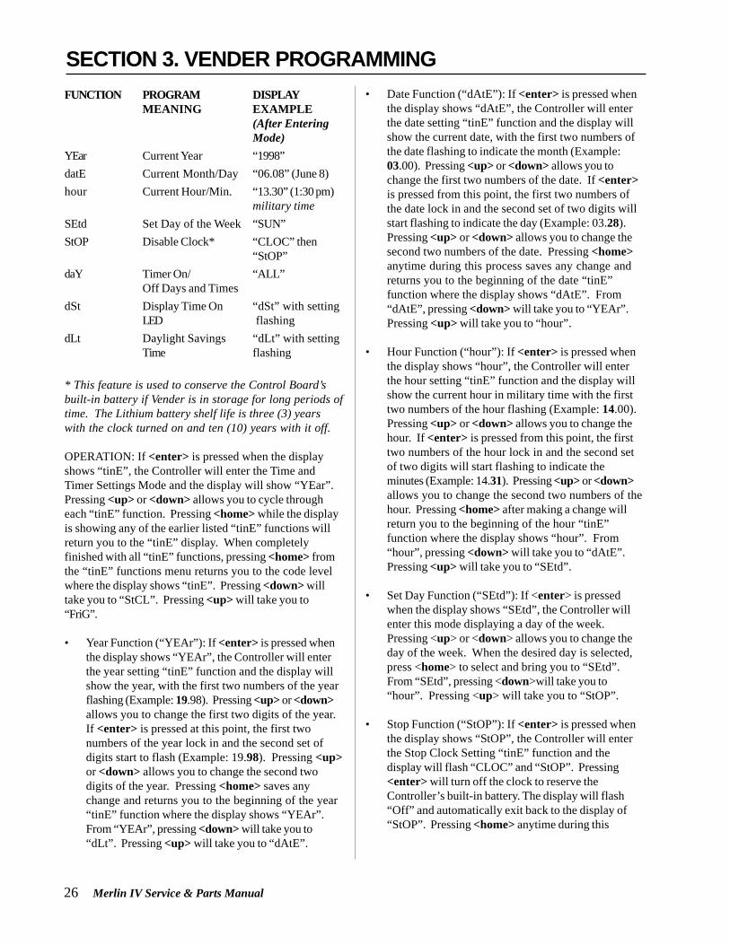
26 Merlin IV Service & Parts Manual
FUNCTION PROGRAM DISPLAYMEANING EXAMPLE
(After EnteringMode)
YEar Current Year “1998”datE Current Month/Day “06.08” (June 8)hour Current Hour/Min. “13.30” (1:30 pm)
military timeSEtd Set Day of the Week “SUN”StOP Disable Clock* “CLOC” then
“StOP”daY Timer On/ “ALL”
Off Days and TimesdSt Display Time On “dSt” with setting
LED flashingdLt Daylight Savings “dLt” with setting
Time flashing
* This feature is used to conserve the Control Board’sbuilt-in battery if Vender is in storage for long periods oftime. The Lithium battery shelf life is three (3) yearswith the clock turned on and ten (10) years with it off.
OPERATION: If <enter> is pressed when the displayshows “tinE”, the Controller will enter the Time andTimer Settings Mode and the display will show “YEar”.Pressing <up> or <down> allows you to cycle througheach “tinE” function. Pressing <home> while the displayis showing any of the earlier listed “tinE” functions willreturn you to the “tinE” display. When completelyfinished with all “tinE” functions, pressing <home> fromthe “tinE” functions menu returns you to the code levelwhere the display shows “tinE”. Pressing <down> willtake you to “StCL”. Pressing <up> will take you to“FriG”.
• Year Function (“YEAr”): If <enter> is pressed whenthe display shows “YEAr”, the Controller will enterthe year setting “tinE” function and the display willshow the year, with the first two numbers of the yearflashing (Example: 19.98). Pressing <up> or <down>allows you to change the first two digits of the year.If <enter> is pressed at this point, the first twonumbers of the year lock in and the second set ofdigits start to flash (Example: 19.98). Pressing <up>or <down> allows you to change the second twodigits of the year. Pressing <home> saves anychange and returns you to the beginning of the year“tinE” function where the display shows “YEAr”.From “YEAr”, pressing <down> will take you to“dLt”. Pressing <up> will take you to “dAtE”.
• Date Function (“dAtE”): If <enter> is pressed whenthe display shows “dAtE”, the Controller will enterthe date setting “tinE” function and the display willshow the current date, with the first two numbers ofthe date flashing to indicate the month (Example:03.00). Pressing <up> or <down> allows you tochange the first two numbers of the date. If <enter>is pressed from this point, the first two numbers ofthe date lock in and the second set of two digits willstart flashing to indicate the day (Example: 03.28).Pressing <up> or <down> allows you to change thesecond two numbers of the date. Pressing <home>anytime during this process saves any change andreturns you to the beginning of the date “tinE”function where the display shows “dAtE”. From“dAtE”, pressing <down> will take you to “YEAr”.Pressing <up> will take you to “hour”.
• Hour Function (“hour”): If <enter> is pressed whenthe display shows “hour”, the Controller will enterthe hour setting “tinE” function and the display willshow the current hour in military time with the firsttwo numbers of the hour flashing (Example: 14.00).Pressing <up> or <down> allows you to change thehour. If <enter> is pressed from this point, the firsttwo numbers of the hour lock in and the second setof two digits will start flashing to indicate theminutes (Example: 14.31). Pressing <up> or <down>allows you to change the second two numbers of thehour. Pressing <home> after making a change willreturn you to the beginning of the hour “tinE”function where the display shows “hour”. From“hour”, pressing <down> will take you to “dAtE”.Pressing <up> will take you to “SEtd”.
• Set Day Function (“SEtd”): If <enter> is pressedwhen the display shows “SEtd”, the Controller willenter this mode displaying a day of the week.Pressing <up> or <down> allows you to change theday of the week. When the desired day is selected,press <home> to select and bring you to “SEtd”.From “SEtd”, pressing <down>will take you to“hour”. Pressing <up> will take you to “StOP”.
• Stop Function (“StOP”): If <enter> is pressed whenthe display shows “StOP”, the Controller will enterthe Stop Clock Setting “tinE” function and thedisplay will flash “CLOC” and “StOP”. Pressing<enter> will turn off the clock to reserve theController’s built-in battery. The display will flash“Off” and automatically exit back to the display of“StOP”. Pressing <home> anytime during this
SECTION 3. VENDER PROGRAMMING

Merlin IV Service & Parts Manual 27
process will return you to the beginning of the StopClock “tinE” function where the display shows“StOP”. From the “StOP” display, pressing <down>will take you to “hour”. Pressing <up> will take youto “dAY”.
• Day Function (“dAY”): If <enter> is pressed whenthe display shows “dAY”, the Controller will enterthe “tinE” function to allow you to set the timer on/off times for each day of the week. The display willshow “ALL”. From this point you have two differentoptions: the All Day Timer Setting will enable you toset all days the same in which the timer operates(such as “ALL” of the price mode) and IndividualDay Timer Settings will give you the option to set allthe timer operations different daily. Pressing <up> or<down> allows you to cycle from “ALL” to each dayof the week. If <enter> is pressed, either at “ALL” ora week day, the Controller will enter into that particu-lar day. The display will show “SC-1”, then “On”,and then the current first “Off” time for selections aslisted below. From here on, this will be referred to asthe Timer Setting Mode Viewing Only Level. If <up>or <down> is pressed at the Timer Setting ModeViewing Only Level, the display will cycle to all otheravailable Timer Setting Modes:
SETTING MODE PROGRAM MEANING“SC-1”... “On” 1st OFF time for selections“SC-1”... “Off” 1st ON time for selections“SC-2”... “On” 2nd OFF time for selections“SC-2”... “Off” 2nd ON time for selections“SC-3”...“On” 3rd OFF time for selections“SC-3” ...“Off” 3rd ON time for selections“dScn”... “On” ON time for discounted
selections“dScn”... “Off” OFF time for discounted selec-
tions“FriG”... “On” OFF time for Refrigeration
System“FriG”... “Off” ON time for Refrigeration
System“Lt-1”... “On” 1st OFF time for illumination
(ballast lighting)“Lt-1”... “Off” 1st ON time for illumination
(ballast lighting)“Lt-2”... “On” 2nd OFF time for illumination
(ballast lighting)“Lt-2”... “Off” 2nd ON time for illumination
(ballast lighting)
“Lt-3”... “On” 3rd OFF time for illumination(ballast lighting)
“Lt-3” ...“Off” 3rd ON time for illumination(ballast lighting)
To set “On” and “Off” times for the timer, you mustpress <enter> upon reaching the desired TimerSetting Mode. After doing this, the Controller willenter into that particular Timer Setting Mode. Thedisplay will show the current setting with the hourflashing. This indicates that the hour can now bechanged. Pressing <up> or <down> allows you tochange the hour of this particular setting. Pressing<enter> will lock in the hour setting and start theminutes flashing (which will indicate to you theminutes can now be changed). Pressing <up> or<down> allows you to change the minutes of thissetting. Pressing <home> anytime during thisprocess will lock in your changes and bring you backto where the display shows the Timer Setting Modeand the time set for that mode (Timer Setting ModeViewing Only Level).
At this point, <up> or <down> allows you to accessall Timer Setting Modes listed earlier. From thisTimer Setting Mode Viewing Only Level, pressing<home> again will return you to the day of the weeklevel. Press <home> again to return to the display of“dAY”. From “dAY”, pressing <down> will take you to“StOP”. Pressing <up> will take you to “dSt”.
Note: If you are setting certain selections to go offand come back on at a programmed time, you mustfirst enter “SC-1 On” to set the first off time forselections. When done programming the first offtime, you must then program the first return on timefor the selections by entering into “SC-1 Off” andprogramming your return on time. For the timer tobe able to control the selections, you must set theselections to be controlled in the “StCL” Mode ofthe Password Protected Menu.
• Display Time Function (“dSt”): If <enter> is pressedat this display, the Controller will enter the DisplayTime Setting Mode and the display will show “dSt”while flashing the current setting. Pressing <up> or<down> allows you to change the flashing settingback and forth between 0 and 1. If set to “1”, thetime of day will be displayed on the LED during thegreeting. If set to “0”, the time will not be displayedduring the greeting. Pressing <home> anytimeduring the process will save changes and return you
SECTION 3. VENDER PROGRAMMING

28 Merlin IV Service & Parts Manual
to the “dSt” display. From this point, pressing<down> will take you to “dAY”. Pressing <up> willtake you back to “dLt”.
• Daylight Savings Time Function (“dLt”): This optionallows for the automatic adjustment of DaylightSavings Time. If enabled, the time will automaticallybe adjusted forward one hour at 2:00 a.m. (2:02 a.m.at the latest) on the first Sunday of April and simi-larly adjusted back one hour on the last Sunday ofOctober. If <enter> is pressed at this display, theControl Board will enter the Daylight Savings TimeEnable / Disable Mode. The display will show “dLt”and flash the current setting. Pressing <up> or<down> allows you to change the flashing settingback and forth between 0 and 1. If set to “1”,Daylight Savings Time will be enabled. If set to “0”,Daylight Savings Time will be disabled. Pressing<enter> anytime during the process will save anychange and returns you to the start of the DisplayTime Mode where the display will show “dLt”. Fromthis point, pressing <down> will take you to “dSt”.Pressing the <up> button will take you to the “yEAr”mode.
Note: This is important if you are using the timerfunction set to “1”.
Refrigeration ParametersMode (FriG)
This mode is used to control the environmental aspects ofthe Vender. It controls the Refrigeration System byallowing you to program the cut in and cut out tempera-tures of the refrigeration unit. The “FriG” Mode alsoallows you to show the current inside cabinet temperature(on the LED during the greeting). The temperaturesshown on the LED during the greeting and programmingcan be changed from Fahrenheit to Celsius. The “FriG”Mode has a relay mode allowing you to test any control-ling relays in the Vender (evaporation fan, refrigeration,ballast, and heater). There is even a setting to disable theunit for safety reasons. Within the “FriG” Mode, thereare several different functions listed below with ameaning and an example for each.
Note: The “FriG” Mode is only applicable in Vendersusing Electronic Refrigeration Mode. However, if the“FriG” setting is set to “1”, without the use of electroniccontrol, the display will show unnecessary “FriG”errors.
Function Program Display ExampleMeaning (After Entering Mode)
Cuti Cut In Temperature 41F
Cuto Cut Out Temperature 29F
dEG Select Fahrenheit Or Celsius
dSP Display Inside Cabinet (evap.)Temperature
FrG Master Control On/Off
rELY Relay Test Mode
OPERATION: If <enter> is pressed when the displayshows “FriG”, the Controller will enter the RefrigerationParameters Mode and the display will show “Cuti”.Pressing <up> or <down> allows you to cycle through allsix (6) “FriG” functions. When completely finished withall programming in the “FriG” Mode, pressing <home>,while the display is showing any of the earlier listed“FriG” functions, will return you to the “FriG” display.From “FriG”, pressing <down> will take you to “tinE”.Pressing <up> will take you to “PAS”.
• Cut In Function (“Cuti”): If <enter> is pressed whenthe display shows “Cuti”, the Controller will enter theCut In Setting “FriG” function and the display willshow the current Cut In Temperature Setting (Factorysetting: 41°F). Pressing <up> or <down> allows youto change the Cut In Setting. The setting can beadjusted between 39°F to 45°F (4°C to 7°C). Pressing<home> anytime during this process will save anychange and returns you to the beginning of the“Cuti” “FriG” function where the display shows“Cuti”. From “Cuti”, pressing <down> will take youto “rELY”. Pressing <up> will take you to “Cuto”.
• Cut Out Function (“Cuto”): If <enter> is pressedwhen the display shows “Cuto”, the Controller willenter the Cut Out Setting “FriG” function. Thedisplay will show the current Cut Out TemperatureSetting (Factory setting: 29°F). Pressing <up> or<down> will allow you to change the Cut OutSetting. The setting can be adjusted between 24°F to34°F (-4°C to 1°C). Pressing <home> anytimeduring this process will save any change and returnsyou to the beginning of the “Cuto” “FriG” functionwhere the display shows “Cuto”. From “Cuto”pressing <down> will take you to “Cuti”. Pressing<up> will take you to “dEG”.
SECTION 3. VENDER PROGRAMMING
FriG

Merlin IV Service & Parts Manual 29
• Select Degree Function (“dEG”): If <enter> ispressed when the display shows “dEG”, the Control-ler will enter the Degree Setting “FriG” function. Thedisplay will show “dEG” and flash the current degreesetting. Pressing <up> or <down> will allow you tochange the current setting. Program to “F” forFahrenheit (Factory Setting) or “C” for Celsius.Pressing <home> anytime during this process willsave any change and returns you to the beginning ofthe “dEG” “FriG” function where the display shows“dEG”. From “dEG”, pressing <down> will take youto “Cuto”. Pressing <up> will take you to “dSP”.
• Display Temperature Function (“dSP”): If <enter> ispressed when the display shows “dSP”, the Control-ler will enter the Display Temperature “FriG”function. The display will show “dSP” and flash thecurrent setting. Pressing <up> or <down> allows youto change the current setting. Program to “1” todisplay the temperature on the LED display duringthe sales greeting or “0” to not display the tempera-ture during the greeting. Pressing <home> anytimeduring this process will save any change and returnsyou to the beginning of the “dSP” “FriG” functionwhere the display shows “dSP”. From “dSP”,pressing <down> will take you to “dEG”. Pressing<up> will take you to “FrG”.
• Unit Disable (Master On/Off) Function (“FrG”): If<enter> is pressed when the display shows “FrG”,the Controller will enter the Unit Disable “FriG”function. The display will show “FrG” and flash thecurrent setting. Pressing <up> or <down> allowsyou to change the current setting. Program to “1”(Electronic Refrigeration Factory Setting) for therefrigeration unit to operate normally or “0” todisable unit. Pressing <home> anytime during thisprocess will save any change and returns you to thebeginning of the “FrG” “FriG” function where thedisplay shows “FrG”. From “FrG”, pressing <down>will take you to “dSP”. Pressing <up> will take youto “rELY”.
• Relay Test Function (“rELY”): If <enter> is pressedwhen the display shows “rELY”, the Controller willenter the relay “FriG” function to allow you to testthe various Vender relays. The display will show“Fan” (which is the test mode for the optionalEvaporator Fan Motor Relay). Pressing <up> or<down> allows you to cycle through each relay testmode available.
RELAY TEST MEANINGMODE MENU
Fan Evaporator Fan Relay Test(requires optional kit)
Htr Heater Relay Test (requiresoptional kit)
LitE Illumination Relay Test(requires optional kit)
CnPr Compressor Relay Test
If <enter> is pressed at any of the four (4) relay testmodes, the display will flash the name of the relayand then flash off. If the relay is currently off andyou wish to enable it, <enter> here. If not, pressingeither <up> or <down> allows the display to flash thename of the relay and then flash off. If the relay iscurrently off and you wish to test the circuit byturning it on, <enter> here. If the circuit tested doesnot work, you have five (5) minutes in Test Mode tocheck voltage. Pressing <home> from within anyrelay Test Mode (if after a test) will allow you toreturn to the Relay Test Mode Menu (where thedisplay will show the name of the relay menu youwere just in). Pressing <home> from a point on theRelay Test Mode Menu returns you to the beginningof the Relay Mode (where the display shows “rELY”).
External Menu Password Setting Mode (PAS)
With the MERLIN IV Vender, you have the capability toaccess both total historical and individual selection cancounts externally. You are also able to read Vender errorsexternally (errors cannot be cleared externally). The“PAS” Mode gives you the option to change the externalpassword to any of your select buttons in a four-digitcombination, or you may decide it best to use the factorysetting of 1 - 3 - 2 - 4 (earlier software versions used 4 -2- 3- 1). If you do decide to set your own password andhappen to forget it, just access this menu and the currentpassword will be displayed.
HELPFUL HINTS1. Password numbers range from 0 to 9.2. If your Vender only has seven selections, you cannot
use 8, 9, or 0 in your password or you will not beable to enter the password.
SECTION 3. VENDER PROGRAMMING
PAS

30 Merlin IV Service & Parts Manual
3. To disable the external password, set one of the four(4) digits to “0” or a selection that is not available (asdescribed in Hint #2).
OPERATION: If <enter> is pressed when the displayshows “PAS”, the Controller will enter the ExternalPassword Setting Mode. The display will show thecurrent external password with the first number of thefour (to extreme left of display) flashing. Pressing <up> or<down> allows you to change the flashing digit. If<enter> is pressed, the second number from the left willstart flashing. By doing this, you lock in any changesmade to the first digit and you are now able to change thesecond digit. Follow the same process for every digit. Ifthe fourth digit is flashing and <enter> is pressed, youwill return to “PAS”. Pressing <home> any time duringthis process locks in your setting and returns you to the“PAS” display. From “PAS”, pressing <down> will takeyou to “FriG”. Pressing <up> will take you to “LAnG”.
International LanguageSetting Mode (LAnG)
The MERLIN IV Vender gives you the opportunity to setan international languages of English, French, Spanish,Hebrew, or German to show vending messages, such as“sold out,” to the customer.
OPERATION: If <enter> is pressed when the displayshows “LAnG”, the Controller will enter the InternationalLanguage Setting Mode. The display will show thecurrent language being used. Pressing <up> or <down>allows you to change the language to one of the follow-ing:EnGL English LanguageHEbr Hebrew LanguageFrEn French LanguageGEr German LanguageSPAn Spanish Language
Pressing <home> anytime during this process saves anychange and returns you to the “LAnG” display. From“LAnG”, pressing <down> will take you to “PAS”.Pressing <up> will take you to “rtn”.
Return to Sales /Greeting Mode (rtn)
This mode is used to exit the Service Menu and return tothe Sales Mode, where the display flashes the greeting(ICE COLD or PEPSI COLA) along with any other displayoptions.OPERATION: If <enter> is pressed when the displayshows “rtn”, the Controller will revert to the Sales Modeand the greeting will be displayed. From “rtn”, pressing<down> will take you to “LAnG”. Pressing <up> will takeyou to “CASH”.
External MenuBy entering the correct four-digit password when Venderis in stand-by condition (display is showing the greeting,a credit is not established, and the Vender is not set forfree vend), you will access the External Menu. This menuconsists of three (3) menu items previously discussed inthe Internal Menu. The External Menu is designed togive you access to a few features, such as total andindividual (per selection) vend counts, Vender errordiagnostics, and a clearing feature for individual vendcounts. This menu may come in handy for a locationmanager who does not have access to the inside of theVender but wishes to report problems and get vendcounts. Programming CANNOT be done through thismenu! After five (5) minutes without activity, if money isinserted or if the coin return lever is actuated, theControl Board will revert to the Sales Mode (the LEDwill show the greeting).
Sale Counter Mode (SALE)This mode is very similar to the Cash
Counter Mode. The Sale Counter Mode allows you tomanually extract the amount of product vended from yourVender (up to 99,999,999 vends). The Sale Counter Modeconsists of a non-resettable total count and individualselection counts. These are resettable depending uponthe proper configuration setting (see Configurations).The counts will be preceded by the count type and canbe displayed in one (1) or two (2) sets of four (4) digits.Examples for both types of Sale Counters are as follows:
SECTION 3. VENDER PROGRAMMING
rtn
LAnG
SALE

Merlin IV Service & Parts Manual 31
OPERATION: If <enter> is pressed when the displayshows “Eror”, the Controller will enter into the ErrorsDescriptive Display Mode. At this point, the display willshow any and all current Vender errors followed by thedescriptions for each. If no errors exist, “none” willappear on the display. If <home> is pressed anytimeduring this operation, the Controller will return to the“Eror” display. From “Eror”, pressing <down> will takeyou to “rtn”.
CLEARING ERRORS: To clear an error, you must accessthe “Eror” Mode from within the Password ProtectedMenus.
Count Actual 1st 2nd 3rdType Count Display Display Display
Total Sale 5,678,910 “SALE” “567” “8910”Count
Selection 678,910 “SL [number]” “67” “8910”Sale Count
OPERATION: If <enter> is pressed when the displayshows “SALE”, the Control Board will enter the SaleCounter Mode. The display will flash “SALE” and thetotal amount of sales made by the Vender, possibly in two(2) sets of four (4) digits (see Example 1 above). Using<up> or <down> will cycle through individual selectionsale counts. The display will flash individual selectioncounts (see Example 2 above). If <home> is pressedanytime during this operation, the Controller will return tothe “SALE” display. From “SALE”, pressing <down> willtake you to “Eror”. Pressing <up> will take you to “rtn”(if present).
Return to Sales /Greeting Mode (rtn)
This mode is used to exit the External Menu and return tothe Sales Mode where the display flashes the greeting(ICE COLD or PEPSI COLA) along with any other displayoptions.
OPERATION: If <enter> is pressed when the displayshows “rtn”, the Controller will revert to the Sales Modeand the greeting will be displayed. From “rtn”, pressing<down> will take you to “Sale”. Pressing <up> will takeyou to “Eror”.
Errors Mode (Eror)This mode was designed to help diagnose
Vender problems. Upon entering this mode, the displaywill flash any possible error (for a list, refer to Section 6,Vender Maintenance: Error Codes). If there are no errors,the display will momentarily flash “none” and revert to“Eror” on the External Menu. Errors cannot be clearedfrom this External Errors Menu. They have to be clearedfrom the Internal Menu.
SECTION 3. VENDER PROGRAMMING
Eror
rtn

32 Merlin IV Service & Parts Manual
SECTION 4. VEND CYCLE
Sold-OutUpon selection, the display will cycle to show the vendprogress. After ten (10) to twelve (12) seconds (if a dropof product is not detected), the display will show “sold-out”. A sold out may be due to:1. The column attempted is jammed, therefore product
does not drop,2. The column attempted is genuinely sold out, or3. The sensor is out of adjustment and does not detect
the product drop.4. If any or all selection, doesn’t have a column
assigned, it will read “Sold Out”.
The digital display will indicate “sold out” and flash thesold out lamp. This signals to the customer to makeanother selection or push the coin return lever for a fullrefund. If set for forced purchase, the customer mustmake an initial selection. If the initial selection is sold out,the customer will be allowed a full refund or an alternateselection. If the Vender is totally sold out of a product,illumination of the “sold out” lamp and the “sold out”message on the digital display will be continuous. Nomoney will be accepted into the Vender in a total sold outcondition.
Resetting Sold Out SelectionsA sold out condition is only cleared by the Vender’s doorswitch by opening the Vender’s main door. If a sold outcondition is not cleared, the Controller will not attempt tovend from that selection. The display will not cycle toindicate a vend is in progress. It will automatically show“sold-out” upon pressing the select button (either beforeor after reaching a vend price).
Vend CycleStand-By ConditionIn a Stand-By Condition, the Vender will show thegreeting and possibly the vend price (if set for a singleprice or if all prices are set to same) and a choice of otheroptional features on the LED display. If a select button ispressed prior to reaching the vend price (establishing acredit), the display will show the vend price for thatselection. This will indicate to the customer more moneyis needed for that particular selection.
Establishing CreditAs coins are inserted into the Coin Mechanism, acorresponding credit count will appear on the display.The Coin Mechanism will continue to accept coins untilthe highest vend price has been achieved. All coins inexcess of the vend price will be returned to the coin cup.Once the vend price has been achieved, the ControlBoard will set up a credit enabling a vend to be made forany selection equal to or less than the established credit.
Valid SelectionThe Vender’s Control Board constantly sends a logiclevel signal to the common position of each select switch.When a selection is made, the selection switch closes.This allows the low voltage signal to travel from theswitches common position through the switch and outthe normally open position of that switch to the selectswitch’s harness connection on the Control Board.
Vend SequenceAt this time (if there has not been a previous sold out),the Control Board distributes 24 volts DC through thedoor and cabinet wiring harnesses and directly to the coilof the chosen vend motor. Simultaneously the displaywill scroll. This is an indication to the customer a vend isin progress and to please wait. As the vend motorreceives power, it will turn the rotor in an attempt to venda can.
Product DeliveryAs the can or bottle drops onto the product deliverychute, the vibration from the impact will allow the deliverysensor to send a low voltage signal to the Vender’sControl Board. This indicates that a product has beenvended. After the Control Board receives the sensor’ssignal, it will take into account how the Vender is pro-grammed (set depth) and will act accordingly.
If the first can has just vended, the Control Board will killall power to the vend motor at the exact same time that animpact is registered (this avoids a multiple vend of thenext product to the rear of the cabinet). As the next canvends, the Control Board will cycle the vend motor topick up another load of product. This allows a quickvend, less than three (3) seconds, for the next customer.
Note: The Control Board will go through a learningprocess known as the Learning Mode. It will be reseteither on power down/up or a door opening/closing.This allows the Vender’s Controller to decide which isthe front or rear product. The Learning Mode acts inconjunction with the depth setting to allow for anautomatic reload after the rear can has vended. How itworks: The Controller will notice the first “long-timedout” vend cycle during the learning process. From this,the Controller will know the very next vend will be thefront product.
Merlin IV Service & Parts Manual 33
SECTION 5: VENDER MAINTENANCE
Vender MaintenanceGeneral MaintenanceWHAT TO CLEANA routine cleaning schedule is the best way to insure the optimum possible operation and appearance from your MER-LIN IV Vender.
PART CLEANING METHOD
Control Board* The Vender’s Control Board should always be enclosed inside its coverto protect it. Routine cleaning is not necessary but, if desired, theController’s area may be blown out with compressed air.
Condenser and For efficient operation, the Condenser and Evaporator Coils must be keptEvaporator Coils clear of any dirt or foreign materials. Clean dirt and lint from the Condenser and
Evaporator Coils with a brush, vacuum cleaner, or compressed air.
Cabinet and Vend Steam clean as required. Never use petroleum cleaners orMechanism submerge electronics in water.
* Note: Never use petroleum cleaners or submerge electronics in water. If the Controller is accidentally sprayed withwater, be sure to allow it to dry thoroughly before powering up the Vender.
WHAT TO LUBRICATEA routine cleaning schedule is the best way to insure the optimum possible operation and appearance from your MER-LIN IV Vender.
PART CLEANING METHOD
Latch Strike Nut The Latch Strike Nut should be lubricated periodically with apetroleum base grease.
Inner Door Gasket The door gasket comes from the factory pre-lubricated but should belubricated periodically with a silicone base grease. Apply to the verticalpiece of gasket on the hinged side of the inner door which touches the Vender’smain door. This will help prevent any peel back of the gasket which can causeair leaks into the sealed cabinet resulting in freeze ups.
Refrigeration The Refrigeration System is a sealed unit and does not require anySystem lubrication. Also, the Condenser and evaporator motors do not require any
lubrication.
IMPORTANT SAFETY NOTE: To prevent bodily injury or damaging the electronics, NEVER plug or unplug anyelectrical connectors with power applied.
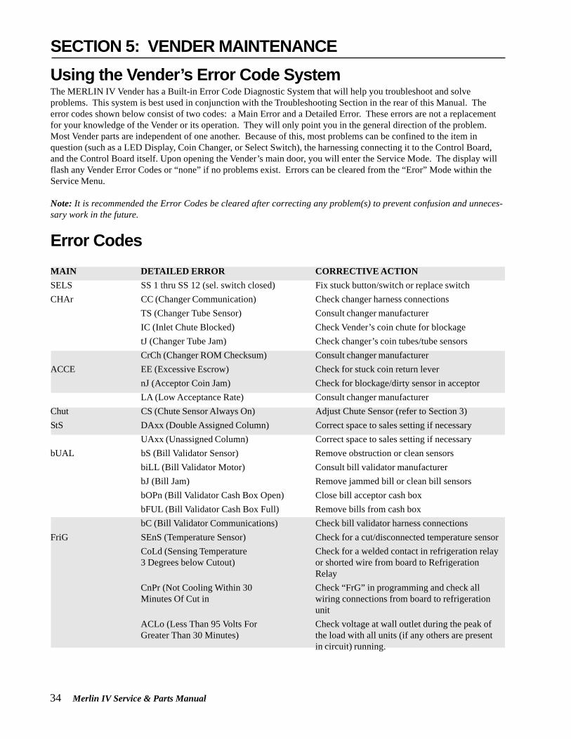
34 Merlin IV Service & Parts Manual
SECTION 5: VENDER MAINTENANCEUsing the Vender’s Error Code SystemThe MERLIN IV Vender has a Built-in Error Code Diagnostic System that will help you troubleshoot and solveproblems. This system is best used in conjunction with the Troubleshooting Section in the rear of this Manual. Theerror codes shown below consist of two codes: a Main Error and a Detailed Error. These errors are not a replacementfor your knowledge of the Vender or its operation. They will only point you in the general direction of the problem.Most Vender parts are independent of one another. Because of this, most problems can be confined to the item inquestion (such as a LED Display, Coin Changer, or Select Switch), the harnessing connecting it to the Control Board,and the Control Board itself. Upon opening the Vender’s main door, you will enter the Service Mode. The display willflash any Vender Error Codes or “none” if no problems exist. Errors can be cleared from the “Eror” Mode within theService Menu.
Note: It is recommended the Error Codes be cleared after correcting any problem(s) to prevent confusion and unneces-sary work in the future.
Error CodesMAIN DETAILED ERROR CORRECTIVE ACTIONSELS SS 1 thru SS 12 (sel. switch closed) Fix stuck button/switch or replace switchCHAr CC (Changer Communication) Check changer harness connections
TS (Changer Tube Sensor) Consult changer manufacturerIC (Inlet Chute Blocked) Check Vender’s coin chute for blockagetJ (Changer Tube Jam) Check changer’s coin tubes/tube sensorsCrCh (Changer ROM Checksum) Consult changer manufacturer
ACCE EE (Excessive Escrow) Check for stuck coin return levernJ (Acceptor Coin Jam) Check for blockage/dirty sensor in acceptorLA (Low Acceptance Rate) Consult changer manufacturer
Chut CS (Chute Sensor Always On) Adjust Chute Sensor (refer to Section 3)StS DAxx (Double Assigned Column) Correct space to sales setting if necessary
UAxx (Unassigned Column) Correct space to sales setting if necessarybUAL bS (Bill Validator Sensor) Remove obstruction or clean sensors
biLL (Bill Validator Motor) Consult bill validator manufacturerbJ (Bill Jam) Remove jammed bill or clean bill sensorsbOPn (Bill Validator Cash Box Open) Close bill acceptor cash boxbFUL (Bill Validator Cash Box Full) Remove bills from cash boxbC (Bill Validator Communications) Check bill validator harness connections
FriG SEnS (Temperature Sensor) Check for a cut/disconnected temperature sensorCoLd (Sensing Temperature Check for a welded contact in refrigeration relay3 Degrees below Cutout) or shorted wire from board to Refrigeration
RelayCnPr (Not Cooling Within 30 Check “FrG” in programming and check allMinutes Of Cut in wiring connections from board to refrigeration
unitACLo (Less Than 95 Volts For Check voltage at wall outlet during the peak ofGreater Than 30 Minutes) the load with all units (if any others are present
in circuit) running.

Merlin IV Service & Parts Manual 35
TroubleshootingUse the following section to troubleshoot your MERLIN IV vender in the case you have a problem in one of thefollowing areas: power, acceptance (coin or bill), vending, or refrigeration. Although we have added what we felt arethe most encountered problems, your specific problem may not be here. If this is the case please, contact your localRoyal Vendors’ service representative.
COIN ACCEPTANCE
TROUBLE POSSIBLE CAUSE CORRECTIVE PROCEDURE
Coin mechanism will No power to Vender’s main door Check to make sure the LED and thenot accept coins (lights not lit) or no power to sign lighting are lit. If not, check
transformer / Control Board power at transformer.
Coin mechanism harness to Control Repair or replace changer harness.Board is cut or disconnected
Short in coin mechanism Unplug all harnessing from the Control Boardexcept the transformer (power) connection,and the coin mechanism connection and testacceptance. If it accepts, replug eachconnection, one at a time, and test acceptanceafter each.
Defective Control Board After a new coin mechanism has been triedand the harness has been checked forcontinuity, replace Control Board.
No acceptance or rejects Coin return lever Make sure changer is mounted correctly andapercentage of good coins the coin return lever is in the proper position.
Acceptor is dirty or foreign Check to ensure that the coin mechanism’smatter is in the path acceptor is clean.
Coin changer is improperly Contact coin changer manufacturer.tuned (if tunable)
Defective Control Board Replace the Control Board and test.
Accepts coins but gives If erratic or no credit: Replace coin mechanism (acceptor) and test. Iferratic/no credit Acceptor (coin mechanism) If OK, check the following.
If no credit, defective harness Check harness for cut wires or wrongbetween coin mechanism and connections. If defective, replace it.Control Board
If no credit, defective Controller Replace Control Board and test.
SECTION 5: VENDER MAINTENANCE

36 Merlin IV Service & Parts Manual
TROUBLE POSSIBLE CAUSE CORRECTIVE PROCEDURE
Changer will not payout Defective harness between coin Check harness for cuts or wrongcoins mechanism and Control Board connections. If defective, replace it.
Defective coin mechanism Replace coin mechanism and test. If it paysout test the Control Board.
Defective Controller Test Vender’s manual coin payout. If Venderpays out using the CPO mode but not duringsales, check the coin mechanism or coinmechanism harness. The Control Board ismore than likely not the problem.
BILL ACCEPTANCE
Validator will not pull in Make sure that the validator Replace defective or wrong validator harness.a bill harnessing is correct for your
style of validator and it isplugged in properly
Acceptance disabled by coin Make sure that the coin mechanism ismechanism or bad harnessing plugged in (accepts coins) and the tubes(validator status light is on) are full of coins.
Make sure that the changer Repair or replace faulty harnessing.harnessing is correctly connected
If validator accepts, replace Replace defective validator.coin mechanism and test.
If validator accepts, replace Replace defective validator.validator and test
If validator accepts, replace Replace defective Controller.Controller and test
Validator takes a bill and Defective (wrong, cut or Make sure that the validator harnessing isnot establishing a credit miswired) validator harnessing. correct for your style of validator and it
(credit not getting from validator is plugged in / wired properly.to Control Board via credit wire)
Defective validator Replace validator and test acceptance.
Defective Controller Replace Controller and test acceptance.
Validator takes a bill Validator switch settings (if any) Refer to validator service manual orand not erasing credit validator representative.
Defective validator interface Refer to validator service manual orharness validator representative
Defective validator Replace validator and test acceptanceand erasure of credit.
Defective Controller Replace Controller and test acceptance anderasure of credit
SECTION 5: VENDER MAINTENANCE

Merlin IV Service & Parts Manual 37
TROUBLE POSSIBLE CAUSE CORRECTIVE PROCEDURE
Validator takes a bill and Controller’s configurations not Access the Venders Configurations Mode andallows payback of coins set properly check the “Forced Attempt” setting.without a selection
VENDING PROBLEMS
Multiple vending If from all selections: delivery Set Venders delivery sensor by turning thesensor cut, not properly grounded, adjustment screw:disconnected, or improperly set 1. clockwise until indicator lights
2. counter clockwise until it goes out3. counter clockwise 1 full turnIf no progress is made by adjusting,replace sensor.Note: Slight adjustments may be needed outsidethe factory set one turn. Turning the adjustmentscrew clockwise makes the sensor moresensitive and counter clockwise makes it lesssensitive. Test vend after every 1/4 turn.
Control Board sending power to Check power at vend motor during multiplemotor when not supposed to vend (24 volts DC). If power is present, the
Control Board is at fault.
Mechanical error Check the vend motor to ensure thegearing within it is OK.
Wrong product vending Misload by Vender loader Ensure all products within each column areupon selection the same.
Space to Sales not set properly Enter Space to Sales and make sure thecolumns are set correctly according to thebuttons.
Miswired motor Check wiring at the each vend motor at thebottom of the Vender’s main door and at themotor’s connection of the Control Board.
Miswired selection Check the wiring at each select switch and atthe select switch’s connection of the ControlBoard.
No vend upon selection - Delivery sensor Check to see if the delivery sensor adjustmentDry vend (no refund) LED is constantly on. If so, turn the adjustment
screw counter clockwise until adjustment LEDgoes out.
Check delivery sensor harness Replace defective sensor.for cuts or pinches. The sensoradjustment LED will constantly beon, if a cut is found.
SECTION 5: VENDER MAINTENANCE

38 Merlin IV Service & Parts Manual
TROUBLE POSSIBLE CAUSE CORRECTIVE PROCEDURE
Unplug the sensors connection Replace defective controller.from the Control Board, if theadjustment LED stays on
No vend from some but not Make sure the LED display Check the select switch and trace theall columns (allows refund acknowledges the selection switch. selections harness back to the Controlor second choice) Board. Replace if necessary.
Individual wire that runs from the If cut or pinched, check individual wiremotor connection of the Control running from motor connection at ControlBoard to the vend motor of the Board to defective column.defective column.
Control Board Measure voltage at vend motor’s connectionof the Control Board. Measure it on theindividual wire for the motor attempted andthe wire by itself next to the key (neutral).A selection must be made and “hold” mustbe displayed on the LED.You should register24 VDC at the vend motor.If not, replace Control Board.
MISCELLANEOUS PROBLEMS
LED not lit If no power, check for 24 volts AC Check transformer and power to transformer.at the Control Board’s powerconnection.
Press Controller’s mode button. If not, check LED lead.Does LED light? Power theVender down and up. Does LEDlight?
LED lead Check the lead for any sign of being pinchedor cut. If so, change the LED.
LED Remove all harnessing but LED lead and thepower lead from transformer to Control Board.Check the new LED before mounting it in theVender. If still bad, replace the Control Boardand test.
SECTION 5: VENDER MAINTENANCE

Merlin IV Service & Parts Manual 39
TROUBLE POSSIBLE CAUSE CORRECTIVE PROCEDURE
Display shows sold out Door switch wiring incorrectly Check for cuts on the two (2) door switchimmediately upon connected, cut , or pinched wires going from the switch to the Controlpressing select button Board. Also check for bad connections atwith column full of the door switch, the plug at the bottom ofproduct (sold-out not the Vender’s main door, and at theControlclearing) Board’s connection. Are any found? If not,
check the door switch.
Door switch Check the door switch to see if it isdefective. If so, replace it.
Control Board Check Control Board by shorting across thetwo (2) pins for the door switch wiring (ControlBoard’s option connection) Does this clear thesold out condition? If so, replace the ControlBoard.
REFRIGERATION PROBLEMS
Refrigeration unit runs Cut out temperature not set properly Check cut out setting in the “FriG” mode.constantly Correct if necessary.
Temperature sensor not reading Test the temperature sensor by showing thecorrectly temperature on the display and measuring the
actual inside cabinet temperature with athermometer or by opening/closing door to seeif the temperature changes. Replace if defective.
Short in wiring harness from Unplug one (1) of the two (2) wires comingController to refrigeration relay from the Control Board to power the relay.
If the unit cuts off, locate the shorted wire to beeither on the door side or the cabinet sideof the harness and correct or replace defectiveharness.
Refrigeration relay’s contacts Unplug one (1) of the two (2) “pink” connectorare welded together wires coming from the Control Board to power
the relay. If the unit continues to run, switch thetwo (2) “blue connector” wires coming from themain wiring harness to the two (2) otheravailable connectors (if present). If not,replace relay.
SECTION 5: VENDER MAINTENANCE

40 Merlin IV Service & Parts Manual
TROUBLE POSSIBLE CAUSE CORRECTIVE PROCEDURE
Refrigeration unit will Unit itself is defective Unplug the refrigeration unit from the top ofnotrun the main wiring harness and plug it into a
direct power source. If it does not run,replace the refrigeration unit.
“FrG” setting not set properly Check “FrG” setting in the “FriG” Mode tomake sure it is set to “1”. If set incorrectly,reprogram it to show “1”
Cut in / Cut out settings not Check cut in /cut out settings. If setset properly incorrectly, reprogram them.
Temperature sensor not Test the temperature sensor by showing thereading correctly temperature on the display and measuring the
actual inside cabinet temperature with athermometer or by opening/closing door to seeif the temperature changes. If found defective,replace temperature sensor.
Short in wiring harness from Unplug the two (2) “pink” connector wiresController to refrigeration relay coming from the Control Board and measure
voltage. You should read approximately24 volts DC from one (1) of the wires. If not,locate the shorted wire to be either on the doorside or the cabinet side of the harness andcorrect or replace defective harness.
Refrigeration relay is defective Test the relay by making sure allconnections are made for the refrigerationunit, the refrigeration relay and the ControlBoard. Next go into the “FriG” mode. Checkthe Compressor by pressing <enter> when youget to “CnPr” and pressing <enter> againwhen the display flashes “CnPr” and “On”.Ifthe unit does not come on, switch the two (2)wires coming from the main wiring harnessto the two (2) other available connectors (ifpresent). If not, replace relay.
SECTION 5: VENDER MAINTENANCE

Merlin IV Service & Parts Manual 41
SECTION 5: REFRIGERATION FLOW CHART
yes
yes
yes
yes
no
yesno
nono
no
no
no
yes
no
yes
yes
no
no
yes
yes
no
yes
no
yes
yes
yes
no
no
yes
no
no
yes
no
yes
no
yes
clos
e ve
nder
s do
oran
d w
ait a
ppro
x.5
min
utes
to s
ee if
ref.
unit
com
es o
n
wai
t to
see
if th
e re
f.un
it st
ops
whe
n th
edi
spla
y r
egis
ters
the
"cut
o" s
ettin
g 29
f
star
tfin
al p
hase
FIN
AL P
HA
SE
noye
s
yes
did
the
unit
com
e on
?
did
the
unit
quit
runn
ing?
chan
ge
mai
n co
ntro
lbo
ard
noch
ange
m
ain
cont
rol
boar
d
prob
lem
solv
ed
chec
k "c
uti"
and
"cut
o"se
tting
s an
d m
ake
sure
that
"ds
p" is
set
to "
1"to
trac
k th
e re
f. un
itste
mpe
ratu
re p
rogr
ess
RE
FR
IGE
RA
TIO
N
TRO
UBLE
SHO
OTI
NG
F
LO
W
CH
AR
T
open
doo
r &
reco
rd e
rror
s*
chec
k vo
ltage
toth
e ev
ap. f
an m
otor
chec
k to
ens
ure
that
the
evap
. coi
ls a
reno
t fro
zen
(if s
o, th
aw)
plug
uni
t int
ow
all o
utle
t
use
cont
rolle
r"c
npr"
rel
ay te
st
unpl
ug c
onne
ctio
n fr
om P
.14
repl
ace
unit
did
unit
star
t and
co
ntin
ue to
run?
do y
ouge
t 24-
28
DC
vol
ts?
Che
ck "
frg"
setti
ngch
eck
volta
ge b
etw
een
pins
1 &
3fr
om th
e m
ain
boar
d **
(P
.14)
do y
ouge
t 24-
28
DC
vol
ts?
chec
k vo
ltage
at
two
whi
te r
elay
wire
s (s
t1 &
2)*
*
repa
ir ha
rnes
sor
rep
lace
tem
p. s
enso
r
repa
ir ha
rnes
sor
rep
lace
tem
p. s
enso
r
chan
ge "
dsp"
set
ting
to "
1" to
sho
w e
vap.
air
tem
p. o
n di
spla
y
is th
e te
mp.
sho
wn
accu
rate
?
repl
ace
mai
n co
ntro
lbo
ard
is th
e te
mp.
sho
wn
accu
rate
?
is h
arne
ss
cut,
smas
hed
or d
isco
nnec
t.?
chec
k te
mp.
sen
sor
harn
ess
for
cuts
repl
ace
defe
ctiv
ete
mpe
ratu
re s
enso
rgo
tofin
al p
hase
go to
final
pha
sego
tofin
al p
hase
go to
final
pha
se
go to
final
pha
se
go to
final
pha
se
go to
final
pha
se
is th
eev
apor
ator
fan
mot
orru
nnin
g?
is th
eev
ap m
otor
rece
ivin
g 11
0?
repl
ace
refr
iger
atio
nre
lay
go to
final
pha
se
go to
final
pha
se
go to
final
pha
se
repl
ace
refr
iger
atio
nre
lay
go to
final
pha
se
repl
ace
evap
orat
orfa
n m
otor
go to
final
pha
se
go to
final
pha
sere
plac
em
ain
wiri
ngha
rnes
s
repa
ir/re
plac
eev
ap. f
an b
lade
and/
or m
otor
is u
nit
runn
ing
with
doo
rcl
osed
?
did
unit
star
t and
co
ntin
ue to
run?
open
doo
r &
reco
rd e
rror
s*
did
unit
quit
runn
ing
upon
ope
ning
door
?
did
unit
quit
runn
ing?
is r
efrig
.un
it of
f?
is a
sh
ort
foun
d?
unpl
ug 1
of t
he 2
whi
tere
lay
wire
s (s
t1 &
2)
from
the
refr
ig. r
elay
repl
ace
refr
iger
atio
nre
lay
repl
ace
mai
n co
ntro
lbo
ard
look
for
a sh
ort
in o
ne o
f the
setw
o w
hite
wire
s
is th
eev
ap. f
anbl
ade
inta
ct?
repl
ace
defe
ctiv
e te
mp.
sens
or
prog
ram
corr
ect s
ettin
gs
chan
ge "
dsp"
set
ting
to "
1" to
sho
w e
vap.
air
tem
p. o
n di
spla
y
is th
e te
mp.
sho
wn
accu
rate
?
is h
arne
ss
cut,
smas
hed
or d
isco
nnec
t.?
chec
k te
mp.
sen
sor
harn
ess
for
cuts
chec
k "c
uti"
and
"cut
o"
setti
ngs
go to
final
pha
se
go to
final
pha
se
go to
final
pha
se
go to
final
pha
se
repa
ir ha
rnes
sor
rep
lace
tem
p. s
enso
r
is th
isse
tting
corr
ect?
*nor
mal
err
ors
are
"cnp
r" a
nd "
cold
" fo
r th
is ty
pe o
f pro
blem
.**
for
volta
ge to
be
read
. you
mus
t firs
t
enab
le th
e co
mpr
esso
r (v
ia th
e "r
ely"
m
ode.
**
*for
this
type
of p
robl
em it
is r
ecom
men
ded
th
at th
e se
tting
s be
41
(cut
i) &
29
(cut
o)
STA
RT
HE
RE
Rev
. A10
/00
Sta
rt
Che
ck fo
r11
0 V
at
pow
er c
ord
is "
frg"
set
to
"1"
?pr
ogra
m "
frg"
to "
1"
no
chec
k "c
uti"
and
"cut
o"
setti
ngs
go to
fina
lP
hase
are
thes
e se
tting
s co
rrec
t***
?
chan
gem
ain
cont
rol
boar
d
no
yes
prog
ram
corr
ect s
ettin
gs
go to
final
pha
se
prog
ram
cor
rect
setti
ngs
Not
e: T
empe
ratu
re S
enso
r to
lera
nce
is +
/- 1
deg
ree
F
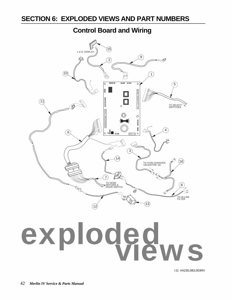
42 Merlin IV Service & Parts Manual
L.E.D. DISPLAY
10
92
15
5
4
TO IN-LINEFILTER
8
14TO COIN CHANGER, VALIDATOR, etc.
TO VEND MOTORS & DOOR SWITCH
3
7
6
1312
11TO SELECTSWITCHES
1
16
I.D. #A235,083,003RV
SECTION 6: EXPLODED VIEWS AND PART NUMBERSControl Board and Wiring
explodedviews

Merlin IV Service & Parts Manual 43
Control Board and WiringITEM # DESCRIPTION PART NUMBER
1 Control Board ................................................................................................ 8361012 LED Display Lead ......................................................................................... 8420813 Serial Changer Harness ............................................................................... 8420794 Delivery Sensor (includes harness) .............................................................. 8360045 Select Switch Harness, Pepsi Cola 10 Select .............................................. 842190
Select Switch Harness, Live Display Vender ................................................ 8421926 Main Door Harness (vend motor/door switch wiring) .................................... 8421697 Cabinet Harness, 12 Column Mechanism (Wide) ........................................ 842174
Cabinet Harness, 10 Column Mechanism (Narrow) ..................................... 842231-1521 and after (Wide) ................................................................................. 842230-1521 and after (Narrow) .............................................................................. 842231
8 Merlin IV Harness Assy. 117V Line ............................................................... 8421519 Internal HH. Phone Jack and Harness ......................................................... 84209910 Temperature Sensor (includes harness) ....................................................... 82203011 Refrigeration Relay Harness, Door Side ...................................................... 84223612 Refrigeration Relay Harness, Cabinet Side .................................................. 84223713 Relay (to control refrigeration system) .......................................................... 83606514 Transformer Assembly .................................................................................. 842147
Merlin IV Harness, Transformer and Fuse to Board ..................................... 842210Fusebox Assembly ........................................................................................ 842219
15 LED Display .................................................................................................. 83601216 MDB Harness ................................................................................................ 842116
SECTION 6: EXPLODED VIEWS AND PART NUMBERS

44 Merlin IV Service & Parts Manual
7
7 88
4
3
9
1
2
5
6Port Assembly
I.D. #A235,069,003RV
SECTION 6: EXPLODED VIEWS AND PART NUMBERS
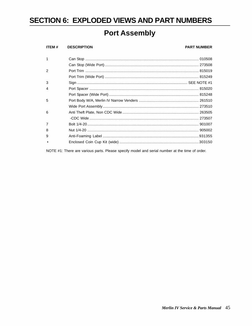
Merlin IV Service & Parts Manual 45
Port AssemblyITEM # DESCRIPTION PART NUMBER
1 Can Stop .............................................................................................................. 010508Can Stop (Wide Port) ........................................................................................... 273508
2 Port Trim .............................................................................................................. 815019Port Trim (Wide Port) ........................................................................................... 815249
3 Sign ........................................................................................................... SEE NOTE #14 Port Spacer .......................................................................................................... 815020
Port Spacer (Wide Port) ....................................................................................... 8152485 Port Body W/A, Merlin IV Narrow Venders .......................................................... 261510
Wide Port Assembly ............................................................................................. 2735106 Anti Theft Plate, Non CDC Wide .......................................................................... 263505
-CDC Wide .......................................................................................................... 2735077 Bolt 1/4-20 ............................................................................................................ 9010078 Nut 1/4-20 ............................................................................................................ 9050029 Anti-Foaming Label ............................................................................................. 931355 • Enclosed Coin Cup Kit (wide) ............................................................................. 303150
NOTE #1: There are various parts. Please specify model and serial number at the time of order.
SECTION 6: EXPLODED VIEWS AND PART NUMBERS

46 Merlin IV Service & Parts Manual
4
16
15
11
6
5
14
3
7
8
8
9
10
1
2
1411
1312
Inner Door Assembly
I.D.# A235,043,003RV
SECTION 6: EXPLODED VIEWS AND PART NUMBERS

Merlin IV Service & Parts Manual 47
Inner Door AssemblyITEM # DESCRIPTION PART NUMBER
1 Inner Door Assembly 79” Wide Venders ......................................... 261640Inner Door Assembly 79” Narrow Venders ...................................... 258630Inner Door Assembly 79” Dr Pepper Vision 4 .................................. 271640Inner Door Assembly 72” Wide Venders ......................................... 262660Inner Door Assembly 72” Narrow Venders ...................................... 264630Inner Door Assembly 72” Dr Pepper Vision 4 .................................. 272640
2 Inner Door Gasket 79” Wide Venders .............................................. 815033Inner Door Gasket 79” Narrow Venders .......................................... 815218Inner Door Gasket 72” Wide Venders .............................................. 815032Inner Door Gasket 72” Narrow Venders .......................................... 815219
3 Port Door Frame .............................................................................. 8151914 Port Door .......................................................................................... 8151925 Port Door Rod ...................................................................................8110286 Elastic Stop Nut ................................................................................ 9050067 Burst Open Latch ............................................................................. 8120028 Bushing, 1.37" .................................................................................. 9160039 Cable Clamp .................................................................................... 91600410 1/8” Rivet .......................................................................................... 90800211 Inner Door Bushing .......................................................................... 81502612 Inner Door Hinge (Top) .................................................................... 01052013 Nut, 8-32 .......................................................................................... 90500114 Self Drilling Screw W/ Washer ......................................................... 90200115 Inner Door Hinge, Bottom ................................................................ 01055016 Self Tapping 1/4 - 20 X 1” ................................................................ 901003 • Space to Sales Decal M-IV (10 column vender) .............................. 931301 • Space to Sales Decal M-IV (12 column vender) .............................. 931302
SECTION 6: EXPLODED VIEWS AND PART NUMBERS

48 Merlin IV Service & Parts Manual
4
Main Door
4
12
14
11
13
10
2120
194
1615
24
22
26
4
23
Cabinet Base
8
7
2
3
2
19
54
6
17
25
27
28
18
Main Door Hinge, Lifter & T-Handle Assemblies
I.D.# A235,044,003RV
SECTION 6: EXPLODED VIEWS AND PART NUMBERS

Merlin IV Service & Parts Manual 49
ITEM # DESCRIPTION PART NUMBER1 Universal Hinge .............................................................................. 164550
-Top Hinge ..................................................................................... 8100022 Bearing Nyliner ............................................................................... 9160123 5/8” Keps Nut .................................................................................. 9050164 Self Tapping 1/4 - 20 X 1” ............................................................... 9010035 Carriage Bolt 1/4 - 20 X 1 1/4” ........................................................ 9010086 Keps Nut 1/4 - 20 ............................................................................ 9050027 Flat Washer .................................................................................... 9040028 Bottom Hinge Bracket W/A ............................................................. 0100409 Top Hinge Spacer ........................................................................... 01001610 Door Roller Spacer ......................................................................... 01001511 Door Roller Bracket ..............................................................SEE NOTE #212 Door Roller ........................................................................... SEE NOTE #213 Door Roller Pin ..................................................................... SEE NOTE #214 Retainer Ring 5/32” ........................................................................ 90600515 Key ........................................................................................ SEE NOTE #116 Lock ......................................................................................SEE NOTE #117 T-Handle Body ...................................................................... SEE NOTE #218 Pin ......................................................................................... SEE NOTE #219 “T” Handle Stud ..................................................................... SEE NOTE #220 Spring .................................................................................... SEE NOTE #221 Retainer Ring ....................................................................... SEE NOTE #222 Nut Retainer ................................................................................... 01002823 Latch Strike, Merlin IV ...................................................................... 01002724 Square Nut 3/4 X 1/2 - 13 ............................................................... 90500525 Latch Strike Assembly, Merlin IV ..................................................... 01003026 T-Handle Assembly (shown) .......................................................... 812001
“Flush Mount” T-Handle Assy used w/ CDC (Prior to 1521) .......... 812176 -1521 and after .............................................................................. 812289
27 Door Roller Assembly .................................................................... 14118028 Leveling Leg ................................................................................... 803002
NOTE #1: There are various parts. Please specify model and serial number at the time of order.
NOTE #2: This part is not available individually. It must be ordered as an assembly.
Main Door Hinge, Lifter & T-Handle AssembliesSECTION 6: EXPLODED VIEWS AND PART NUMBERS

50 Merlin IV Service & Parts Manual
1
2
3
17
4
513
OPTIONAL
98 7
10
12 11 11
1214
16
15
6
Refrigeration System Assembly
I.D.# A235,045,003RV
SECTION 6: EXPLODED VIEWS AND PART NUMBERS

Merlin IV Service & Parts Manual 51
ITEM # DESCRIPTION PART NUMBER
1 Heat Exchange ....................................................................................... 2104252 Dryer .......................................................................................................8240053 Condenser .............................................................................................. 8200074 Condenser Fan Motor Assembly (w/Blade) ............................................ 839010
Condenser Fan blade ............................................................................. 8100145 Screw, #8-32x1/2” ................................................................................... 9010066 1/3+ H.P. Capacitor Start Compressor .................................................... 8190287 Compressor Relay 1/3+ H.P. (Tecumseh Only) ...................................... 8220428 Compressor Overload 1/3+ H.P. (Tecumseh Only) ................................. 8220109 Compressor Lead ........................................................................... See note #210 Grommets, Compressor ..........................................................................91601511 Grommets Plugs .....................................................................................81501712 Clip, Compressor ....................................................................................91400213 Thermostat .............................................................................................. 82200114 Screw, #8x1/2” ........................................................................................ 90200415 Evaporator Fan Shroud Assembly, Wide ................................................ 256080
Evaporator Fan Shroud Assembly, Narrow ............................................. 25807016 Evaporator Coil ....................................................................................... 82000217 Refrigeration System, Merlin IV 1/3+ H.P. .............................................. 256420 • Evaporator Cover ................................................................................... 256004
Note #2: This part is not available individually. It must be ordered as an assembly.
Refrigeration System AssemblySECTION 6: EXPLODED VIEWS AND PART NUMBERS

52 Merlin IV Service & Parts Manual
2
1
3
5
6
7
4
8
9
Evaporator Fan Motor Assembly
I.D.# A235,006,003RV
SECTION 6: EXPLODED VIEWS AND PART NUMBERS

Merlin IV Service & Parts Manual 53
ITEM # DESCRIPTION PART NUMBER1 Fan Blade .................................................................................................. n/a2 Nut 1/4-20 ...........................................................................................9050023 Silencer ..................................................................................................... N/A4 Motor, 35w. / 115v. ...................................................................................... n/a5 Machine Screw #8-32x1/2" .................................................................9010386 Fan Plate ............................................................................................0100587 Well Nut ..............................................................................................9050268 Fan Mounting Bracket .........................................................................0100579 Screw #8-32x3/8" ................................................................................ 901011• Evaporator Fan Motor Assembly, 35 w (all items) ..............................303121
Evaporator Fan Motor AssemblySECTION 6: EXPLODED VIEWS AND PART NUMBERS

54 Merlin IV Service & Parts Manual
Vend Mechanism Assembly
I.D.# A235,046,003RV
SECTION 6: EXPLODED VIEWS AND PART NUMBERS1
4
5
23 6
7
8
3
910
9
10
12
11
13
16
14
15
17
18
19
20

Merlin IV Service & Parts Manual 55
ITEM # DESCRIPTION PART NUMBER
1 Vend Mechanism Assembly, 12 Col. 79” Vender ................................ 256710Vend Mechanism Assembly, 12 Col. 72” Vender ................................ 262720Vend Mechanism Assembly, 10 Col. 79” Vender ................................ 258710Vend Mechanism Assembly, 10 Col. 72” Vender ................................ 264710
2 Case Support, Wide ........................................................................... 811026Case Support, Narrow ........................................................................ 811033
3 Self Drilling Screw ............................................................................... 902004Hitch Pin Clip (some venders may have pins) .................................... 906023
4 Rubber Strip ........................................................................................ 9151995 1/8” Rivet ............................................................................................. 9080026 Screw, #8-32x3/8” ............................................................................... 9010117 Rod Retainer ....................................................................................... 2567148 Rotor Rod ............................................................................................ 8030359 Vend Motor, Merlin IV ...........................................................................839031
-1618 and Before ................................................................................83902910 Rotor, Merlin IV ....................................................................................81530511 Front Rotor Bearing ............................................................................91515612 Rear Rotor Bearing ............................................................................91522213 Product Retainer, Left (79” Vender) ....................................................256716
Product Retainer, Left (72” Vender) ....................................................25770614 Product Retainer, Right (79” Vender) .................................................256715
Product Retainer, Right (72” Vender) .................................................25770515 Backspacer Assembly (79” Vender) ...................................................256730
Backspacer Assembly (72” Vender) ...................................................25773016 Funnel Angle .......................................................................................25671917 Rotor Assembly, Front Column ..........................................................25674018 Rotor Assembly, Rear Column ...........................................................25675019 Anti-friction Sheet ................................................................................91519720 Can Funnel .........................................................................................256712
Vend Mechanism AssemblySECTION 6: EXPLODED VIEWS AND PART NUMBERS

56 Merlin IV Service & Parts Manual
Miscellaneous Assemblies
I.D.# A235,047,003RV
SECTION 6: EXPLODED VIEWS AND PART NUMBERS
189
15
14
8
3
4
5
519
2
20
89
6 6
13
affafds
affafds
affafds
affafdsaffafdsaffafdsaffafdsa
ffafdsaffafds
17
11
12
6
21
22
6
25
24
23
26
27
8
28
1010
10
7
16
9
9
1
109
8
29
Rear View of Vender
3031
32
33
34
35
36
37
38

Merlin IV Service & Parts Manual 57
Miscellaneous AssembliesSECTION 6: EXPLODED VIEWS AND PART NUMBERS
ITEM # DESCRIPTION .......................................................................... PART NUMBER
1 Refrigeration System .................................................................................. 2564202 Delivery Chute Sensor ................................................................................ 8360043 Delivery Chute Liner, Wide Vender ............................................................ 815262
Delivery Chute Liner, Narrow Vender ......................................................... 8152704 Delivery Chute, Wide Vender ..................................................................... 256005
Delivery Chute, Narrow Vender .................................................................. 2580015 Tension Clips .............................................................................................. 9160596 Rivets, 1/8” ................................................................................................. 9080047 Evaporator Cover ....................................................................................... 2560048 Self Tapping Screw, 1/4-20x1” .................................................................... 9010039 Self Drilling Screw, #8x1/2” ........................................................................ 90200410 “U” Clips ...................................................................................................... 90600711 Pepsi Door Weld Assembly, 10 Sel. 79” Wide Vender ............................... 227510
Pepsi Door Weld Assembly, 8 Sel. 79” Narr. Vender ................................. 263510Cold Drink Door Weld Assembly, 10 Sel. 79” W.V. .................................... 216510Cold Drink Door Weld Assembly, 8 Sel. 79” N.V. ....................................... 268510
12 Inner Door Assembly 79” Wide Vender ...................................................... 271640Inner Door Assembly 79” Narrow Vender ................................................... 258630Inner Door Assembly 72” Wide Vender (Dr Pepper Vision IV) ................... 272640Inner Door Assembly 72” Narrow Vender ................................................... 264630
13 Vend Mechanism Assembly, 12 Column 79” Vender ................................. 256710Vend Mechanism Assembly, 12 Column 72” Vender ................................. 262720Vend Mechanism Assembly, 10 Column 79” Vender ................................. 258710Vend Mechanism Assembly, 10 Column 72” Vender ................................. 264710
14 Evaporator Fan Motor Assembly ................................................................ 21040015 Grounding Wire .............................................................................................. Misc.16 Evaporator Fan Housing, Wide Vender ...................................................... 256080
Evaporator Fan Housing, Narrow Vender .................................................. 25807017 Inner Door Cover Assembly, Wide Vender ................................................. 81525918 Latch Strike Assembly ................................................................................ 01003019 Bracket, Chute Locator ............................................................................... 14101420 Can Chute Tie Bracket ............................................................................... 01001721 PC Board Cover ......................................................................................... 14190322 Right Cabinet Vandal Panel 79” (specify color) .......................................... 012122
Right Cabinet Vandal Panel 72” (specify color) ........................................... 01100223 Left Cabinet Vandal Panel 79” (specify color) ............................................ 010022
Left Cabinet Vandal Panel 72” (specify color) ............................................. 01100124 Mech. Support, W/A ................................................................................... 25601325 Mech. Support, 3 Deep .............................................................................. 05800126 In-Line Filter Assembly ................................................................................ 01112427 Main Wiring Harness .................................................................................. 84206328 Can Chute Assembly, Wide Vender ........................................................... 256070
Can Chute Assembly, Narrow Vender ........................................................ 25800129 Condenser Baffle ........................................................................................ 010403
Condenser Baffle (Narrow M-IV) ................................................................ 25840130 Rear Baffle .................................................................................................. 01003731 Condensate Pan ......................................................................................... 81536832 Sponge ....................................................................................................... 81503733 Self Drilling Screw ...................................................................................... 90200434 Drain Tube .................................................................................................. 81513435 Door Switch (Before P.O. 1521) ................................................................. 83500336 Door Switch (1521 and after) ..................................................................... 83501937 Door Switch Actuator .................................................................................. 23100938 Pop Rivet .................................................................................................... 908018 • Caster Kit Assembly, Heavy Duty M-IV ...................................................... 256130 • Mesh Cabinet Back (Wide) ........................................................................ 141001
-Narrow ...................................................................................................... 258004 • Steel Cabinet Back (Wide) ......................................................................... 010215
-Steel Narrow ............................................................................................. 258005 • Drain Hose Clip .......................................................................................... 906025

58 Merlin IV Service & Parts Manual
3
4
1
75
9
6
8
2
12
10
13
11
14
15
Door Assembly, Front
I.D.# A235,048,003RV
SECTION 6: EXPLODED VIEWS AND PART NUMBERSCold Drink 1533 & beforeW/A 10 Sel. 79" W ............. 216510 -8 Sel N ............................. 268510Left Side Trim 79" W .......... 032505 -72" .................................... 019507Top Trim W ......................... 032504 -Narrow ............................. 044513Bottom Trim Wide .............. 032504 -Narrow ............................. 044514Right Side Trim 79" Wide ... 032506 -72" .................................... 019508

Merlin IV Service & Parts Manual 59
Door Assembly, FrontSECTION 6: EXPLODED VIEWS AND PART NUMBERS
ITEM # DESCRIPTION...................................................................... PART NUMBER
1 Pepsi Door Weld Assembly, 10 Sel. 79” Wide Vender .............................. 227570Pepsi Door Weld Assembly, 8 Sel. 79” Narrrow Vender ........................... 263580
2 Sign ................................................................................................. SEE NOTE #13 Right Vandal Panel 79” (Specify color) ...................................................... 010519
Right Vandal Panel 72” (Specify color) ..................................................... 0115014 Rain Guard, Wide Venders ........................................................................ 2585045 Top Door Hinge ......................................................................................... 8100026 Carriage Bolt, 1/4-20x1/2” ......................................................................... 9010077 Self Drilling Screw, #8x1/2” ........................................................................ 9020048 “T”-Screw 8-32 ........................................................................................... 9010019 Top Door Bushing ..................................................................................... 80300310 Left Side Trim 79” Wide Vender ................................................................ 142502
Left Side Trim 72” Wide Vender ................................................................ 019507Left Side Trim 72” Narrow Vender, Pepsi .................................................. 142502
11 Top Trim Wide Vender ............................................................................... 012553Top Trim Narrow Vender ........................................................................... 040807
12 Bottom Trim Wide Vender ......................................................................... 012553Top/Bottom Trim (M4) Narrow Vender ....................................................... 040811
13 Right Side Trim 79” Wide Vender .............................................................. 012554Right Side Trim 72” Wide Vender .............................................................. 013507Right Side Trim 72” Narrow Vender .......................................................... 019508
14 Left Vandal Panel, 79” (Specify color) ....................................................... 141002Left Vandal Panel, 72” (Specify color) ....................................................... 142001
15 Pop Rivet ................................................................................................... 908018 • Christmas Tree ......................................................................................... 916009
NOTE #1: There are various parts. Please specify model and serial number at the time of order
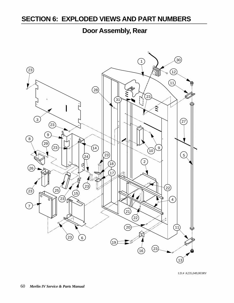
60 Merlin IV Service & Parts Manual
7
23 619
20
23
23
23
18
17
24
15
23
25
98
233
23
9
12
11
27
23
28
11
13
21
22
22
105
2
4
23
23
26
1
14
16
29
30
31
I.D.# A235,049,003RV
Door Assembly, RearSECTION 6: EXPLODED VIEWS AND PART NUMBERS

Merlin IV Service & Parts Manual 61
ITEM # DESCRIPTION PART NUMBER
1 Door Weld Assembly, 10 Sel. 79” Wide Vender .................................... 227570Door Weld Assembly, 8 Sel. 79” Narrrow Vender ................................. 263580Cold Drink Door Weld Assembly, 10 Sel. 79” W.V (1533 & before). ..... 216510Cold Drink Door Weld Assembly, 8 Sel. 79” N.V (1533 & before). ........ 268510
2 Port Body Welded Assembly (Narrow Port) .......................................... 210510Port Body Welded Assembly (Wide Port) .............................................. 273560
3 Lamp Guard, Wide Venders .................................................................. 012514Lamp Guard, Narrow Vender, Merlin IV ................................................. 258505
4 Port Brace, Wide Venders ..................................................................... 010515Port Brace, Narrow Vender, Merlin IV ..................................................... 258506
5 Lamp, Slimline For 79” Vender ............................................................. 841005Lamp, Slimline For 72” Vender ............................................................. 841006
6 Coin Box Housing (1405 & after) .......................................................... 2735407 Coin Box Welded Assembly (1405 & after) ........................................... 8153478 Coin Hopper .......................................................................................... 8150159 Changer Door ........................................................................................ 01054410 Ballast Assembly, 79” Wide Vender, Non CDC ..................................... 012940
-72”, Non CDC ...................................................................................... 013920 -79”, CDC .............................................................................................. 198920 -72”, CDC .............................................................................................. 195910
11 Lamp Bracket ........................................................................................ 01051712 Top Lampholder .................................................................................... 84200313 Bottom Lampholder .............................................................................. 84200414 Changer Door Hinge Assembly, Top ..................................................... 01057015 Changer Door Hinge Assembly, Bottom ............................................... 01056016 Bottom Inner Door Hinge ...................................................................... 01055017 Latch Roller Bracket .............................................................................. 01051618 Burst Open Latch Strike ......................................................................... 81200319 Self Tapping Screw, 1/4-20x1” ............................................................... 90100320 Self Drilling Screw, #8-32 ...................................................................... 90200421 Carriage Bolt, 1/4-20x1/2” ..................................................................... 90100722 Keps Nut, 1/4-20 ................................................................................... 90500223 Sems Screw, #8-32x3/8” ....................................................................... 90101124 Pop Rivet, 1/8” ....................................................................................... 90800425 Bottom Coin Chute Assembly (To Coin Box) ........................................ 01259326 Hopper Chute Assembly (To Coin Cup) ............................................... 01253827 Door Rod ............................................................................................... 81100128 Elastic Stop Nut ..................................................................................... 90500429 Screw #8-32x1/2" with washers ............................................................ 90100630 Transformer Assembly .......................................................................... 01057231 Fusebox Assembly ................................................................................ 842219
Door Assembly, RearSECTION 6: EXPLODED VIEWS AND PART NUMBERS
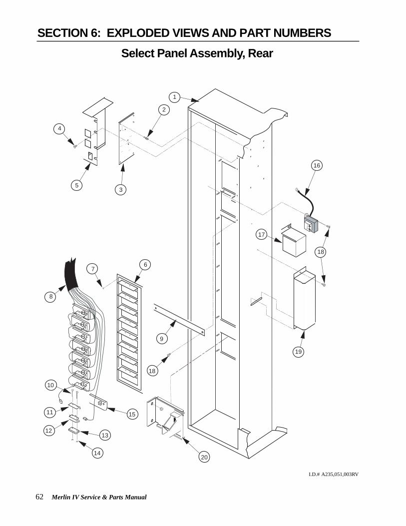
62 Merlin IV Service & Parts Manual
15
18
13
14
12
11
10
9
76
19
16
18
17
2
4
8
53
1
20
Select Panel Assembly, Rear
I.D.# A235,051,003RV
SECTION 6: EXPLODED VIEWS AND PART NUMBERS

Merlin IV Service & Parts Manual 63
ITEM # DESCRIPTION PART NUMBER
1 Door Weld Assembly, 10 Sel. 79” Wide Vender .................................... 227570Door Weld Assembly, 8 Sel. 79” Narrow Vender ................................... 263580Cold Drink Door Weld Assembly, 10 Sel. 79” WV (1533 & before) ....... 216510Cold Drink Door Weld Assembly, 8 Sel. 79” NV (1533 & before) ......... 268510
2 PC Board Spacer ................................................................................... 9160273 Control Board ........................................................................................ 8361014 Self Drilling Screw, #8-18x1/2” .............................................................. 9020045 Control Board Cover .............................................................................. 1419036 Control Panel Welded Assembly, 10 Select ......................................... 017530
Control Panel Welded Assembly, 8 Select ............................................ 0125107 Keps Nut, #8-32 .................................................................................... 9050018 Select Switch Harness .................................................................. See Note #19 Panel Strap (optional) ............................................................................ 01053110 Screw ..................................................................................................... 90104111 Spring Shield ......................................................................................... 81516412 Switch (large) ......................................................................................... 83501213 Switch Spacer ........................................................................................ 81501814 Keps Nut ................................................................................................ 90501815 Button Assembly .................................................................................... 81502516 Transformer Assembly ) ........................................................................ 01057217 Transformer Cover ................................................................................ 01006318 Self Tapping Screw, #8-32x3/8” ............................................................. 90100219 Ballast, Slimline .................................................................................... 83800220 Coin Return Cup (Steel) ........................................................................ 012595 • Splash Guard (protect sel. switches) .................................................... 815303NOTE #1: There are various parts. Please specify model and serial number at the time oforder.
Select Panel Assembly, RearSECTION 6: EXPLODED VIEWS AND PART NUMBERS
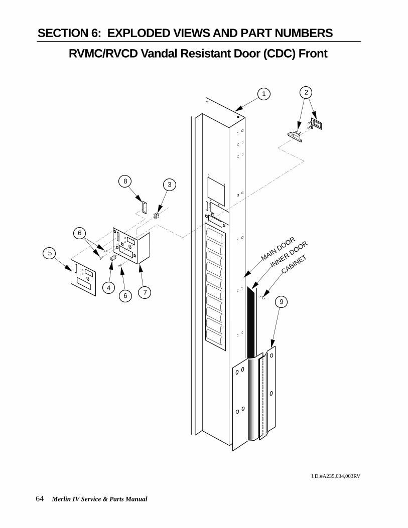
64 Merlin IV Service & Parts Manual
4
6
8
5
7
3
9
21
MAIN DOOR
CABINETINNER DOOR
6
RVMC/RVCD Vandal Resistant Door (CDC) Front
I.D.#A235,034,003RV
SECTION 6: EXPLODED VIEWS AND PART NUMBERS
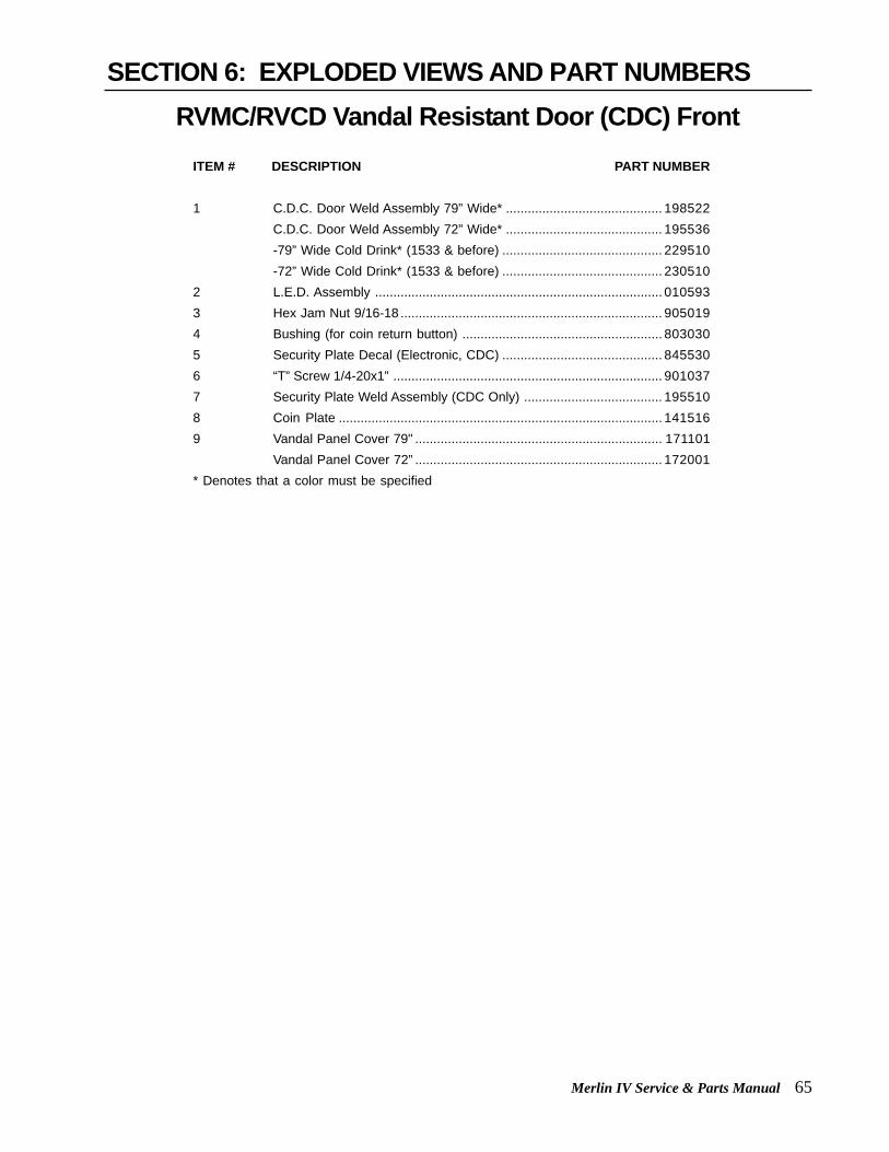
Merlin IV Service & Parts Manual 65
ITEM # DESCRIPTION PART NUMBER
1 C.D.C. Door Weld Assembly 79” Wide* ........................................... 198522C.D.C. Door Weld Assembly 72” Wide* ........................................... 195536-79” Wide Cold Drink* (1533 & before) ............................................ 229510-72” Wide Cold Drink* (1533 & before) ............................................ 230510
2 L.E.D. Assembly ............................................................................... 0105933 Hex Jam Nut 9/16-18 ........................................................................ 9050194 Bushing (for coin return button) ....................................................... 8030305 Security Plate Decal (Electronic, CDC) ............................................ 8455306 “T” Screw 1/4-20x1” .......................................................................... 9010377 Security Plate Weld Assembly (CDC Only) ...................................... 1955108 Coin Plate ......................................................................................... 1415169 Vandal Panel Cover 79" .................................................................... 171101
Vandal Panel Cover 72” .................................................................... 172001* Denotes that a color must be specified
RVMC/RVCD Vandal Resistant Door (CDC) FrontSECTION 6: EXPLODED VIEWS AND PART NUMBERS

66 Merlin IV Service & Parts Manual
RVMC/RVCD Vandal Resistant Door (CDC) Rear
I.D.#A235,036,003RV
SECTION 6: EXPLODED VIEWS AND PART NUMBERS
11
14
15
13
12
10
9
8
6
5
24
7
2523
22
1918
17
2021
2
3
4
4
3
16
1
26

Merlin IV Service & Parts Manual 67
ITEM # DESCRIPTION PART NUMBER
1 CDC Door Weld Assembly 79” Wide .................................................... 198522CDC Door Weld Assembly 72” Wide .................................................... 195536 -79” Wide ,Cold Drink (1533 & before) ................................................. 229510 -72” Wide ,Cold Drink (1533 & before) ................................................. 230510
2 Validator Security Door .......................................................................... 1415213 Spring Hinge (for Security Doors) ......................................................... 9121564 Pop Rivet 1/8” ........................................................................................ 9080045 Coin Ramp ............................................................................................ 1415086 Nut 1/4-20 .............................................................................................. 9050027 Lever Stop .............................................................................................. 1415148 Select Panel Harness .................................................................SEE NOTE #19 Button Panel Weld Assembly-10 select ................................................ 017530
Button Panel Weld Assembly-7 select .................................................. 03452010 Screw ..................................................................................................... 90104111 Button Assembly .................................................................................... 81502512 Spring Shield ......................................................................................... 81516413 Switch, Large ......................................................................................... 83501214 Switch Spacer ........................................................................................ 81501815 Nut ......................................................................................................... 90501816 Cash Box Guard (Security Door) ............................................................ 01114717 Coin Return Spring ................................................................................ 91402318 Button Lever (Coin Return Lever) .......................................................... 16150919 Roller Pin (5/32”) ................................................................................... 81100220 Hinge, Button Lever ............................................................................... 16150821 Retaining Ring (for 5/32” Diameter Rod) .............................................. 90600522 Button, Coin Return Lever ..................................................................... 80303123 Nut #8-32 ............................................................................................... 90500124 T-Handle Brace ...................................................................................... 14151325 T-Handle Housing ................................................................................. 81219026 Lock Cylinder Cover .............................................................................. 161532* Denotes a color must be specified
NOTE #1: There are various parts. Please specify model and serial number at the time of order.
RVMC/RVCD Vandal Resistant Door (CDC) RearSECTION 6: EXPLODED VIEWS AND PART NUMBERS

68 Merlin IV Service & Parts Manual
1
23
15
14
COIN MECH
DETAIL "B"
20
21 18
19
6
DETAIL “B”
7
4
8
9
11
12
DETAIL "A"
5L.E.D. DISPLAY 17
16
DETAIL “A”
13
10
5
22
18
23
24
RVMC/RVCD Center Door Changer Vault
I.D.#A235,088,003RV
SECTION 6: EXPLODED VIEWS AND PART NUMBERS

Merlin IV Service & Parts Manual 69
ITEM # DESCRIPTION PART NUMBER
1 Changer Vault Brace .................................................................................. 1615182 Cable Sleeve (At Each End Of Cable) ....................................................... 9060153 Cable .......................................................................................................... 9110324 Coin Chute Assembly / CDC Wide Vender / 79.5” .................................... 1615905 Button Lever Assembly (see detail “A”) ..................................................... 1615946 Coin Chute Bracket 79.5” .......................................................................... 161527
Coin Chute Bracket 72” ............................................................................. 1625027 Changer Plug Bracket ................................................................................ 0105618 Panel Strap ................................................................................................ 0105319 Control Board ............................................................................................. 83610110 Hopper Mounting Bracket .......................................................................... 16151511 Transformer Assembly, MIV ....................................................................... 842147
Merlin IV Harness, Transformer and Fuse to Board .................................. 842210Fuse, 3.0 ..................................................................................................... 942111
12 Select Panel Plate ..................................................................................... 16151213 Port Body Welded Assembly ..................................................................... 27351014 Changer Vault Welded Assembly .............................................................. 16152315 Port Brace Welded Assembly .................................................................... 16154116 Lock Cylinder Cover (see detail “A”) .......................................................... 16153217 T-Handle Brace (see detail “A”) ................................................................. 14151318 Coin Cup, CDC .......................................................................................... 23150519 Coin Hopper ............................................................................................... 81501520 Coin Box Coin Chute/Back ........................................................................ 231507
Coin Box Coin Chute ................................................................................. 23150621 Anti-Theft Plate .......................................................................................... 161504
Anti-Theft Plate, CDC, Wide ...................................................................... 273507Anti-Theft Plate, Non-CDC, Wide .............................................................. 263505
22 Security Plate Welded Assembly ............................................................... 19551023 Coin Box Welded Assembly ....................................................................... 161570
-Plastic Coin Box ....................................................................................... 81534724 Button Lever Assembly (Coin Return Lever) ............................................. 161593• Coin Insert Assembly ................................................................................. 195560• Changer Vault Door (Not Shown), Optional ............................................... 161534• Board Cover (CDC) .................................................................................... 195518• Coin Deflector ............................................................................................ 161526
RVMC/RVCD Center Door Changer VaultSECTION 6: EXPLODED VIEWS AND PART NUMBERS

70 Merlin IV Service & Parts Manual
11
3
10
2
10 99
4
5
8
7
6
1
Port Assembly, Dr Pepper Vision 4
I.D.#A235,063,003RV
SECTION 6: EXPLODED VIEWS AND PART NUMBERS

Merlin IV Service & Parts Manual 71
ITEM # DESCRIPTION PART NUMBER
1 Port Body Welded Assembly / CDC........................................................... 2315102 Anti-Theft Plate / CDC ............................................................................... 2315043 Coin Cup / CDC ......................................................................................... 2315054 Port Spacer ................................................................................................ 8150205 Sign ................................................................................................. SEE NOTE #16 Port Trim .................................................................................................... 8150197 Can Stop .................................................................................................... 0105088 Anti-Foaming Label .................................................................................... 9313559 Nut 1/4-20 .................................................................................................. 90500210 Carriage Bolt 1/4-20x1/2" ........................................................................... 90100711 Screw #8-32x3/8" ....................................................................................... 901011
NOTE #1: There are various parts. Please specify model and serial number at the time of order.
Port Assembly, Dr Pepper Vision 4SECTION 6: EXPLODED VIEWS AND PART NUMBERS

72 Merlin IV Service & Parts Manual
11
12
4
2
147
9
8
98
6
7
6
1
3
13
10
5
Door Assembly Front, Dr Pepper Vision 4
I.D.#A235,064,003RV
SECTION 6: EXPLODED VIEWS AND PART NUMBERS

Merlin IV Service & Parts Manual 73
ITEM # DESCRIPTION PART NUMBER
1 Main Door Welded Assembly / Vision 4 / CDC 79" ............................... 242537Main Door Welded Assembly / Vision 4 / CD. 72" ................................. 243550
2 Sign, Dr Pepper Vision 4 (Must Give # of Selections) ................ SEE NOTE #13 Rain Guard, Wide Venders .................................................................... 0105184 Top Main Door Hinge ............................................................................. 8100025 Vandal Panel, Right (Door) 79" ............................................................. 010519
Vandal Panel, Right (Door) 72" ............................................................. 0115016 Metal Trim, Right & Left 79" ................................................................... 1715077 Metal Trim, Top and Bottom .................................................................. 1715028 Trim, Right and Left 79" ......................................................................... 2425269 Trim, Top and Bottom ............................................................................ 24252510 Carriage Bolt 1/4-20x1/2" ...................................................................... 90100711 Self Drilling Screw #8x1/2" .................................................................... 90200412 Top Door Bushing ................................................................................. 80300313 Nut 1/4-20 .............................................................................................. 90500214 T-Bolt 1/4-20x1" ...................................................................................... 901037
NOTE #1: There are various parts. Please specify model and serial number at the time of order.
Door Assembly Front, Dr Pepper Vision 4SECTION 6: EXPLODED VIEWS AND PART NUMBERS

74 Merlin IV Service & Parts Manual
1
2
3
4
7
2
6
5
107
7
1514
7
1311
97
1617
7
7
7
8
7 12
Door Assembly Rear, Dr Pepper Vision 4
I.D.#A235,065,003RV
SECTION 6: EXPLODED VIEWS AND PART NUMBERS

Merlin IV Service & Parts Manual 75
ITEM # DESCRIPTION PART NUMBER
1 Main Door Welded Assembly / Vision 4 / CDC 79" ................................. 242537Main Door Welded Assembly / Vision 4 / CDC 72" ................................. 243550
2 Lamp Bracket .......................................................................................... 0105173 Top Lampholder (Springloaded) ............................................................. 8420034 Bottom Lampholder ................................................................................ 8420045 Ballast Assembly ..................................................................................... 2315606 Lamp, H.O. 79" Vender ............................................................................ 841001
Lamp, H.O. 72" Vender ............................................................................ 8410027 Screw #8-32x3/8" ..................................................................................... 9010118 Validator Vault Welded Assembly ............................................................ 2425309 Button Bracket Welded Assembly - DP Vision 4 ..................................... 24255010 Changer Vault Welded Assembly ............................................................ 16152311 Port Body Welded Assembly / CDC ........................................................ 23151012 Validator Vault Brace 79" ......................................................................... 242511
Validator Vault Brace 72" ......................................................................... 24350113 Coin Box Welded Assembly, Vision 4 CDC ............................................ 23155014 Latch Roller Bracket ................................................................................ 24251215 Burst Open Latch Strike ........................................................................... 81200316 Bottom Inner Door Hinge ........................................................................ 01055017 Self Tapping Screw 1/4-20x1" ................................................................. 901003
Door Assembly Rear, Dr Pepper Vision 4SECTION 6: EXPLODED VIEWS AND PART NUMBERS

76 Merlin IV Service & Parts Manual
1
2
3
4
5
8
67
9
3
10
11
12
13
1415
16
17
1819
20
2
921
22
23
24
25
Coin Insert Assembly Front, Dr Pepper Vision 4
I.D.#A235,066,003RV
SECTION 6: EXPLODED VIEWS AND PART NUMBERS

Merlin IV Service & Parts Manual 77
ITEM # DESCRIPTION PART NUMBER
1 Validator Vault Welded Assembly ...........................................................2425302 Nut 1/4-20 ...............................................................................................9050023 Retaining Ring (“C” Clip) .........................................................................9121574 Lock Cylinder Cover................................................................................1615325 Self Tapping Screw #8-32x3/8" ............................................................... 9010116 T-Handle Housing ...................................................................................8121907 Brass Hex Washer .......................................................................SEE NOTE #28 T-Bolt 1/4-20x1" ......................................................................................9010379 Spring, T-Handle ..........................................................................SEE NOTE #210 Pin, T-Handle ..........................................................................................91213311 2 Keys ..........................................................................................SEE NOTE #112 Lock .............................................................................................SEE NOTE #113 T-Handle Body ........................................................................................81213414 T-Handle Stud ..............................................................................SEE NOTE #215 LED Lens ................................................................................................91603216 Security Plate Decal / Dr Pepper Vision 4 .............................................. 84576517 Security Plate Welded Assembly ............................................................ 24252018 Bushing, Button Coin Return ..................................................................80303019 Hex Jam Nut 9/16-18 UNF2A .................................................................90501920 Button, Coin Return Lever ......................................................................80303121 Washer .........................................................................................SEE NOTE #222 Square Nut 3/4x1/2-13 ............................................................................90500523 Nut Retainer ............................................................................................01002824 Latch Strike .............................................................................................24203025 Self Tapping Screw 1/4-20x1" .................................................................901003• Latch Strike Assembly .............................................................................242031• T-Handle Assembly, Vision 4 .................................................................. 812277
NOTE #1: There are various parts. Please specify model and serial number at the time of order.
NOTE #2: This part is not available individually. It must be ordered as an assembly.
Coin Insert Assembly Front, Dr Pepper Vision 4SECTION 6: EXPLODED VIEWS AND PART NUMBERS

78 Merlin IV Service & Parts Manual
23
4
5
6
7
8
910
14
153
16
1718
11
12
133
1
21
20
19
22 2324
25
26
27
28
29
30
CI Rear & Button Panel Assembly, Dr Pepper Vision 4
I.D.#A235,067,003RV
SECTION 6: EXPLODED VIEWS AND PART NUMBERS
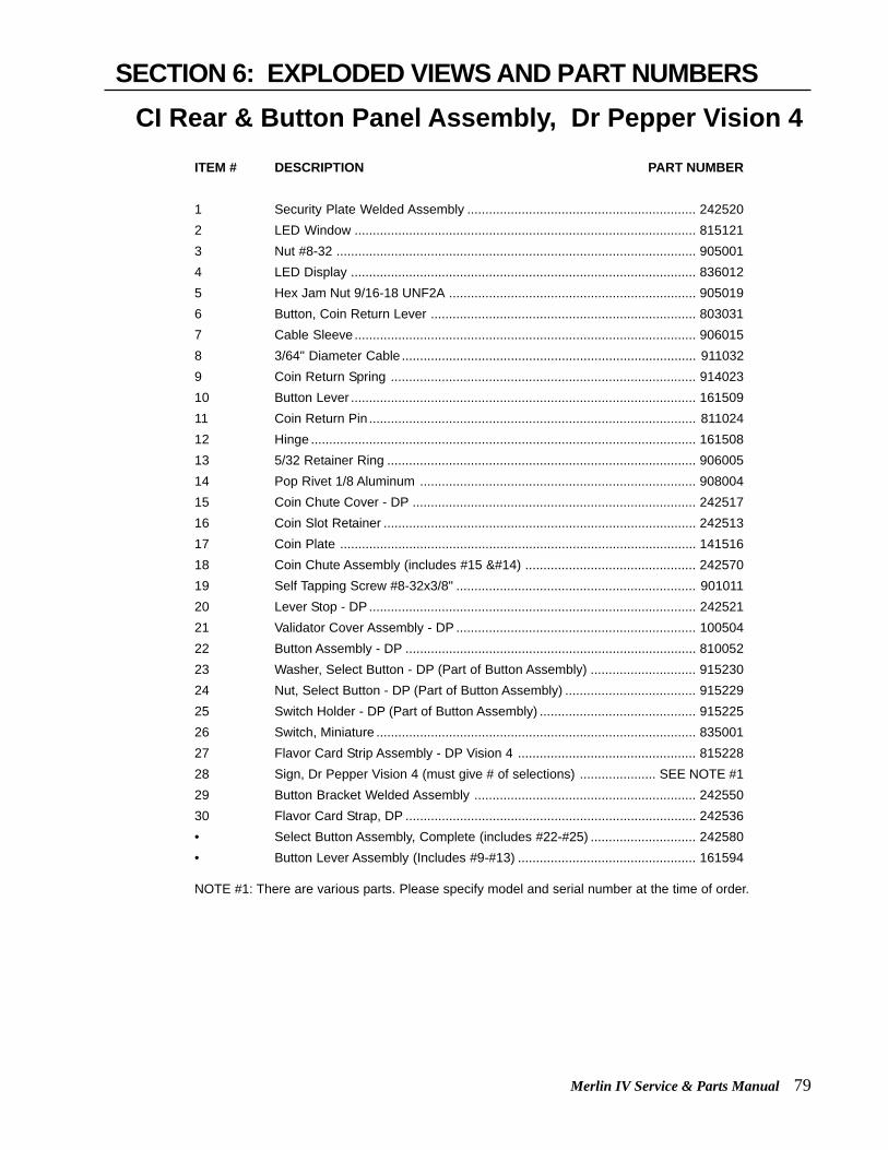
Merlin IV Service & Parts Manual 79
ITEM # DESCRIPTION PART NUMBER
1 Security Plate Welded Assembly ............................................................... 2425202 LED Window .............................................................................................. 8151213 Nut #8-32 ................................................................................................... 9050014 LED Display ............................................................................................... 8360125 Hex Jam Nut 9/16-18 UNF2A .................................................................... 9050196 Button, Coin Return Lever ......................................................................... 8030317 Cable Sleeve.............................................................................................. 9060158 3/64" Diameter Cable ................................................................................. 9110329 Coin Return Spring .................................................................................... 91402310 Button Lever ............................................................................................... 16150911 Coin Return Pin .......................................................................................... 81102412 Hinge .......................................................................................................... 16150813 5/32 Retainer Ring ..................................................................................... 90600514 Pop Rivet 1/8 Aluminum ............................................................................ 90800415 Coin Chute Cover - DP .............................................................................. 24251716 Coin Slot Retainer ...................................................................................... 24251317 Coin Plate .................................................................................................. 14151618 Coin Chute Assembly (includes #15 ) ............................................... 24257019 Self Tapping Screw #8-32x3/8" .................................................................. 90101120 Lever Stop - DP .......................................................................................... 24252121 Validator Cover Assembly - DP .................................................................. 10050422 Button Assembly - DP ................................................................................ 81005223 Washer, Select Button - DP (Part of Button Assembly) ............................. 91523024 Nut, Select Button - DP (Part of Button Assembly) .................................... 91522925 Switch Holder - DP (Part of Button Assembly) ........................................... 91522526 Switch, Miniature ........................................................................................ 83500127 Flavor Card Strip Assembly - DP Vision 4 ................................................. 81522828 Sign, Dr Pepper Vision 4 (must give # of selections) ..................... SEE NOTE #129 Button Bracket Welded Assembly ............................................................. 24255030 Flavor Card Strap, DP ................................................................................ 242536• Select Button Assembly, Complete (includes #22-#25) ............................. 242580• Button Lever Assembly (Includes #9-#13) ................................................. 161594
NOTE #1: There are various parts. Please specify model and serial number at the time of order.
CI Rear & Button Panel Assembly, Dr Pepper Vision 4SECTION 6: EXPLODED VIEWS AND PART NUMBERS

80 Merlin IV Service & Parts Manual
DETAIL “B”
COIN MECH
DETAIL "B"
1
2
3
4
5
6
7
89
10
11
13
3
14153
2 16
12
14
Changer Vault Assembly, Dr Pepper Vision 4
I.D.#A235,068,003RV
SECTION 6: EXPLODED VIEWS AND PART NUMBERS

Merlin IV Service & Parts Manual 81
ITEM # DESCRIPTION PART NUMBER
1 Changer Vault Welded Assembly ..............................................................1615232 Port Brace, DP / CDC ................................................................................2425033 Port Body Welded Assembly / CDC...........................................................2315104 Hopper Mounting Bracket ..........................................................................1615155 Support Bracket, Coin Chute / CDC ..........................................................1615376 Coin Chute Strap - DP ...............................................................................2425167 Coin Chute Assembly (includes #5, #6 and #8) .........................................2425708 Coin Chute Cover - DP ..............................................................................2425179 3/64" Diameter Cable ................................................................................. 91103210 Cable Sleeve..............................................................................................90601511 Changer Vault Brace ..................................................................................24250412 Coin Return Lever Assembly .....................................................................16159313 Coin Box Coin Chute Welded Assembly ...................................................23151914 Coin Cup - CDC .........................................................................................23150515 Anti Theft Plate - CDC................................................................................23150416 Coin Hopper ...............................................................................................815015• Coin Chute Bracket, 79" CDC (Not Shown) ...............................................161527• Water Block, Coin Chute / DP - CDC (Not Shown) ...................................161536
Changer Vault Assembly, Dr Pepper Vision 4SECTION 6: EXPLODED VIEWS AND PART NUMBERS

82 Merlin IV Service & Parts Manual
1
5
6
2
318
1516
17
14
11
13
12
11
10
8
9
19
4
21
20
7
Flat Horizontal Display, Door Front
I.D.#A235,072,003RV
SECTION 6: EXPLODED VIEWS AND PART NUMBERS

Merlin IV Service & Parts Manual 83
ITEM # DESCRIPTION PART NUMBER
1 Door Welded Assembly - Flat Display - 72" .............................................. 2785522 Right Vandal Panel - 72" ........................................................................... 0115013 Coin Return Cup Welded Assembly ......................................................... 0125954 Button Panel - Flat Display - 10 Select ...................................................... 2785025 Rain Guard - Wide Venders ...................................................................... 0105186 Screw #8 x 1/2” .......................................................................................... 9020047 Left Vandal Panel, 79” ............................................................................... 141002
Left Vandal Panel, 72” ............................................................................... 1420018 T-Screw #8-32 ........................................................................................... 9010019 Trim, Top Side ........................................................................................... 03280710 Sign, Top / Flat Display (Cold Drink Graphics) ......................................... 84591811 Trim, Center ............................................................................................... 27851112 Sign, Center / Flat Display ......................................................................... 84591913 Sign, Bottom / Flat Display ........................................................................ 84592014 Trim, Left Side ........................................................................................... 01950715 Port Trim, Wide Port .................................................................................. 81524916 Port Spacer, Wide Port ............................................................................... 81524817 Trim, Bottom Side ...................................................................................... 03280618 Trim, Right Side ......................................................................................... 01950819 Carriage Bolt 1/4-20 x 1/2" ........................................................................ 90100720 Price Label Strip - Top ............................................................................... 27851221 Price Label Strip - Bottom .......................................................................... 278515
Flat Horizontal Display, Door FrontSECTION 6: EXPLODED VIEWS AND PART NUMBERS

84 Merlin IV Service & Parts Manual
5 129
5
5
16
15
17
13
5
14
19
5
26
18
8
5
SELECT BUTTON ASSEMBLY
3130
2928
Button Panel (p/n 278502)(mounted in door weld ass’y)
27
4
4
2
3
520
1
5
6
5
7
1110
2223
21
5
24
5
22
25
21
Sign - Center / Flat Display(p/n 278508)
32
Flat Horizontal Display, Door Rear
I.D.#A235,073,003RV
SECTION 6: EXPLODED VIEWS AND PART NUMBERS

Merlin IV Service & Parts Manual 85
ITEM # DESCRIPTION PART NUMBER
1 Door Welded Assembly - Flat Display - 72" .............................................. 2785522 Pop Rivet 1/8" diameter ............................................................................. 9080043 Display Product Holder ............................................................................. 0231074 Display Back - Flat Display ........................................................................ 2785055 Screw #8 x 1/2" .......................................................................................... 9020046 Port Brace, Wide Vender ........................................................................... 0105157 Nut 1/4-20 .................................................................................................. 9050028 Inner Door Hinge, Bottom ......................................................................... 0105509 Self Tapping Screw 1/4-20 x 1" .................................................................. 90100310 Port Body Welded Assembly - Flat Display ............................................... 27852011 Carriage Bolt 1/4-20 x 1/2” ........................................................................ 90100712 Coin Box Housing ..................................................................................... 01053713 Bottom Changer Door Hinge W/A ............................................................. 01056014 Bottom Coin Chute Assembly (to Coin Box) ............................................. 01259315 Latch Roller Bracket .................................................................................. 01051616 Burst Open Latch Strike ............................................................................. 81200317 Pop Rivet 1/8" dia. Stainless Steel ............................................................ 90800118 Top Changer Door Hinge W/A ................................................................... 01057019 Changer Door ............................................................................................ 01054420 Lamp Panel - Bottom (Single Bulb) .......................................................... 27850721 Screw #8-32 x 1/2" w Flat Washer ............................................................ 90100622 Lamp 20 watt 24" long .............................................................................. 84101223 Ballast - Single Bulb .................................................................................. 838005
Ballast Assembly - Flat Display (Single Bulb) .......................................... 12251824 Lamp Panel - Top (Double Bulb) .............................................................. 27850625 Ballast - Double Bulb ................................................................................ 838024
Ballast Assembly - Flat Display (Double Bulb) ......................................... 12252826 Transformer Assembly .............................................................................. 01057227 Button Assembly ................................................................................ not available28 Washer, Select Button ....................................................................... not available29 Nut, Select Button .............................................................................. not available30 Switch Holder .................................................................................... not available* Complete Button Assembly (items 27, 28, 29, 30) ................................... 81601631 Switch, Miniature ....................................................................................... 83500132 Coin Box W/A ............................................................................................. 010580
Flat Horizontal Display, Door RearSECTION 6: EXPLODED VIEWS AND PART NUMBERS

86 Merlin IV Service & Parts Manual
2
1
5
7
45
5
3
98
5
132
31
30
33
10
1112
13
14
1513
29
27
28
2524
23
26
18
1922
1617
21
20
6
Flat Horizontal Display, Select Panel
I.D.#A235,074,003RV
SECTION 6: EXPLODED VIEWS AND PART NUMBERS

Merlin IV Service & Parts Manual 87
ITEM # DESCRIPTION PART NUMBER
1 Door Welded Assembly - Flat Display - 72" .............................................. 2785522 LED Display Assembly .............................................................................. 0105933 Coin Plate .................................................................................................. 1415164 Security Plate Welded Assembly ............................................................... 2165025 T-Screw 1/4-20 x 1" .................................................................................... 9010376 LED Lens (Part of LED Assembly) ............................................................ 9160327 Security Plate Decal .................................................................................. 8456418 Bushing (for coin return button) ................................................................ 8030309 Hex Jam Nut 9/16-18 ................................................................................. 90501910 T-Handle Assembly (prior to 1521) ........................................................... 812176
-1521 and after ......................................................................................... 81228911 T-Handle Body (part of T-Handle Assembly) ..................................... not available12 Spring, T-Handle Assembly (part of T-Handle Assembly) ................ not available13 Retainer Ring, T-Handle (part of T-Handle Assembly) ..................... not available14 T-Handle Stud (part of T-Handle Assembly) ...................................... not available15 Pin, T-Handle (part of T-Handle Assembly) ....................................... not available16 Button, Coin Return ................................................................................... 80303117 Retaining Ring 5/32" ................................................................................. 90600518 Hinge, Coin Return Lever .......................................................................... 14150619 Pin, Coin Return Lever .............................................................................. 81100220 Coin Return Lever ..................................................................................... 14150421 Screw #8-32 x 3/8" ..................................................................................... 90101122 Spring, Coin Return Lever ......................................................................... 91400323 Nut #8-32 ................................................................................................... 90500124 Coin Ramp ................................................................................................ 14150825 T-Handle Housing ..................................................................................... 81219026 Nut 1/4-20 .................................................................................................. 90500227 Lever Stop .................................................................................................. 14151428 T-Handle Brace .......................................................................................... 14151329 Lock Cylinder Cover .................................................................................. 16153230 Screw #8-18 x 1/2" ..................................................................................... 90200431 Control Board Cover .................................................................................. 14190332 Control Board ............................................................................................ 83610133 PC Board Spacer ....................................................................................... 916027
Flat Horizontal Display, Select PanelSECTION 6: EXPLODED VIEWS AND PART NUMBERS

88 Merlin IV Service & Parts Manual
PROGRAMMING FLOWCHART
Exte
rnal M
en
uS
ALE
rtn
CA
SH
Inte
rnal (S
erv
ice) M
en
u
SA
LE
Ero
r
tES
t
PriC
Sto
S
SdE
P
Con
Opt 0
- Opt 8
CS
tS
ALL
1 - 1
0
set b
y s
ele
ctio
n1 - 1
0LA
nG
EnG
LF
rEn
SP
An
HE
br
GE
rC
uS
t
Cuti
Cuto
dE
Gd
SP
FrG
rEL
Y
FA
n
LitE
Htr
CnP
r
FriG
SC
-1 . . . O
n
SC
-1 . . . O
FF
SC
-2 . . . O
n
SC
-2 . . . O
FF
SC
-3 . . . O
n
SC
-3 . . . O
FF
dS
cn . . . O
n
dS
cn
. . . OF
F
FriG
. . . On
FriG
. . . OF
F
Lt-1
. . . On
Lt-1
. . . OF
F
Lt-2
. . . On
Lt-2
. . . OF
F
Lt-3
. . . On
Lt-3
. . . OF
F
Pro
gra
mm
ing
Flo
wc
ha
rt
Rev C
10/0
1R
tinE
YE
Ar
dA
tEhour
SE
tdS
tOP
dA
Y
AL
L
Su
n - S
at
dS
tdL
t
C1 - C
12
rtn
Ero
r
(If C2 is
set to
"0")
SdiS
StC
LA
LL
1 - 1
0
PA
S
tUF
L
dS
AL
diF
C
EC
O
CP
O
rtn
Op
tion
al M
en
u Ite
ms
(If C2
is s
et to
"1")

Merlin IV Service & Parts Manual 89
Made in the U.S.A.
Royal Vendors’ Publication833021Rev. L 10-01
R