OPERATION AND MAINTENANCE MANUAL -...
26
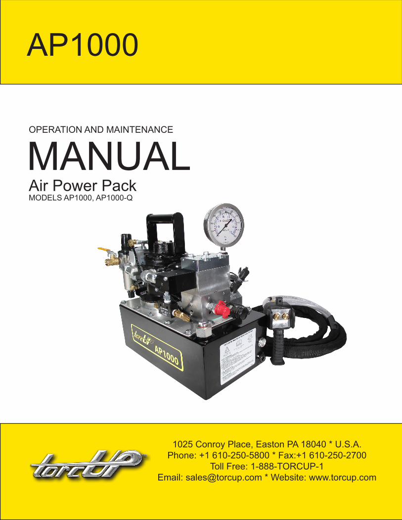
OPERATION AND MAINTENANCE MANUAL Air Power Pack MODELS AP1000, AP1000-Q AP1000 1025 Conroy Place, Easton PA 18040 * U.S.A. Phone: +1 610-250-5800 * Fax:+1 610-250-2700 Toll Free: 1-888-TORCUP-1 Email: [email protected] * Website: www.torcup.com
Transcript of OPERATION AND MAINTENANCE MANUAL -...
OPERATION AND MAINTENANCE
MANUALAir Power PackMODELS AP1000, AP1000-Q
AP1000
1025 Conroy Place, Easton PA 18040 * U.S.A.Phone: +1 610-250-5800 * Fax:+1 610-250-2700
Toll Free: 1-888-TORCUP-1Email: [email protected] * Website: www.torcup.com

Operational and Maintenance Manual for TorcUP AP1000
Version 1: 2013 April
Heavy duty air motor. Powerful 4HP industrial air motor runs on 60cfm/100PSIDisconnect removable pressure gauge. Quadra-Torc function (optional). Quick connect couplers.
Supplied with dual non-conductive high pressure hose with couplers.
TorcUP Inc. is not responsible for customer modification of tools for applications on which TorcUP Inc. was not consulted.
IMPORTANT SAFETY INFORMATION ENCLOSED.READ THIS MANUAL BEFORE OPERATING PUMP.
IT IS THE RESPONSIBILITY OF THE EMPLOYER TO PLACE THE INFORMATION IN THIS MANUAL INTO THE HANDS OF THE OPERATOR.
FAILURE TO OBSERVE THE FOLLOWING WARNINGS COULD RESULT IN INJURY.
The use of other than genuine TorcUP replacement parts may result in safety hazards, decreased tool performance, and increased maintenance, and may
invalidate all warranties. Repairs should be made only by authorizedpersonnel. Consult your nearest TorcUP Authorized Service Center.
Refer All Communications to the Nearest TorcUP Office or Distributor.
For Technical Support & Information Contact:TorcUP Inc.
1025 Conroy Place, Easton, PA 18040 USAPhone: +1 610-250-5800 Fax:+1 610-250-2700
email: [email protected]
Manual Index……………………................1General Warnings………………………….2Safe and Correct Use…………………......3-6Technical Specifications…………….……5-8Working Pressure………………….....……5Install Vent Plug……………………..….…..6Adding Oil…………………………….....…..6Connecting Hydraulic Tools……………...6Pump Mounting………………………….....6
Air Control Buttons........……………………...7Pressure Torque Setting……………………...7Air Motor and Filter Lubricator......................8After Completing the Job……………………..8Periodic Maintenance………………………....9Maintain Oil Level…………………………...….8Clean Oil Intake Screen…………………...…..9Flushing the Pump………………………….… 9Trouble Shooting............................................10AP1000 Parts Index……………………………11-23
CONTENTS
TorcUP has taken every care in preparing this Operational Manual that is intended as a technical guideline only. TorcUP accepts no liability in relation to any use or reliance made of any information in this Operational Manual.
All information, illustrations and specifications in this Operational Manual are based on the latest information avail-able at the time of publication. The right is reserved to make changes at any time without notice.
Equipment operators and installers shall be responsible for ensuring that a safe working environment and safe systems of work are in place before operating the equipment.
1

FAILURE TO OBSERVE THE FOLLOWING WARNINGS COULD RESULT IN INJURY
Do NOT exceed Maximum Pressure. See Torque Chart with Tool. Damage May Occur.
Always wear eyeprotection when operating orperforming maintenance on this tool.
Always wear ear protection when operating this tool. Do not carry
the toolby the hose.
Keep body stance balanced and firm. Do not overreachwhen operating this tool.
USING THE TOOL
• Keep hands, loose clothing & long hair away from the reaction arm and working area during operation. • This tool will exert a strong reaction force. Use proper mechanical support and correct reaction arm positioning to control these forces. Do not position the reaction arm so that it tilts the tool off the axis of the bolt and never use the swivel inlets as a reaction stop.• Avoid sharp bends and kinks that will cause severe back-up pressure in hoses an lead to premature hose failure.• Use accessories recommended by TorcUP. • Use only impact sockets and accessories. Do not use hand (chrome) sockets or accessories.• Use only sockets and accessories that correctly fit the bolt or nut and function without tilting the tool off the axis of the bolt.• This tool is not insulated against electric shock. • This equipment must not be operated or serviced unless the operator read the operating instructions and fully understands the purpose, consequences and procedure of each step.
Depending on the working environment your local health and safety regulations may require you protective gear (i.e. Ear Protection, Safety Shoes, Hard Hat, Gloves, Coveralls, etc.) In case external forces are exerted on the equipment, non-compliance with these regulations may result in injury. EAR PROTECTION MUST BE WORN WHEN OPERATING THIS TOOL.
The Torque Reaction Arm must be positioned against a positive stop. Do not use the arm as a dead handle. Take all precautions to make certain the operator’s hand cannot be pinched between thearm and a solid object.
Do not use damaged, frayed or deteriorated air/pneumatic hoses and fittings.
2

SAFE AND CORRECT USE Operation of the Equipment in Accordance with Specified Use
1. Inspect, maintain, operate and install the tool in accordance with all applicable standards and
regulations (local, state, country, federal, etc.)2. Do not remove any labels. Replace any damaged labels immediately. 3. Be sure all hoses and fittings are the correct size and tightly secured.4. Do not use damage, frayed or deteriorated air hoses and fittings. Do not paint hoses.5. Do not lubricate tools with flammable or volatile liquids such as kerosene, diesel or jet fuel. Use
only TorcUP recommended lubricants.6. Use only proper cleaning solvents to clean parts. Use only cleaning solvents which meet cur-
rently safety and health standards. Use cleaning solvents in a well ventilated area.7. Keep work area clean, uncluttered, ventilated and illuminated.
Safety Information When Using The Tool
1. When wearing gloves always be sure that the gloves will not prevent the throttle mechanism from being released.
2. Always wear eye protection when operating or performing maintenance on this tool.3. Always wear hearing protection when operating this tool.4. Always use personal protective equipment appropriate to the tool used and material worked.
This may include dust mask or other breathing apparatus, safety glasses, ear plugs, gloves, apron, safety shoes, hard hat and other equipment.
5. Keep others a safe distance from your work area, or ensure they use appropriate personal protective equipment.
6. Be aware of buried, hidden or other hazards in your work environment. Do not contact or dam-age cords, conduits, pipes, or hoses that may contain electrical wires, explosive gases or harmful liquids.
7. Keep hands, loose clothing, long hair and jewelry away from working end of tool.8. Power tools can vibrate in use. Vibration, repetitive motions or uncomfortable positions may be
harmful to your hands and arms. Stop using any tool if discomfort, tingling feeling or pain occurs. Seek medical advice before resuming.
9. Keep body stand balanced and firm. Do not overreach when operating this tool. Anticipate and be alert for sudden changes in motion, reaction torques, or forces during start up and operation.
10. DO NOT USE THIS TOOL WHEN TIRED, UNDER THE INFLUENCE OF MEDICATION, DRUGS OR ALCOHOL.
11. Never use a damaged or malfunctioning tool or accessory.12. Do not modify the tools, safety devices or accessories.13. Do not use this tool for purposes other than those recommended14. Never exceed rated pressure of tool.
3

SAFE AND CORRECT USE
IMPORTANT - READ CAREFULLY
This manual contains important information for the correct installation, operation and maintenance of this equipment. All persons involved in the installation, operation and maintenance of this equipment must be thoroughly familiar with the contents of this manual. To safeguard against the possibility of personal injury or property damage, follow the recommendations and instructions of this manual. Keep this manual for reference.
WARRANTY STATEMENT
TorcUP products are warranted to be free of defects in materials and workmanship under normal use for as long as the original purchaser owns them, subject to the guidelines and limitations listed. This warranty does not cover: normal wear & tear, cosmetic items, abuse, overloading, alterations, improper fluid, or use in a manner for which they are not intended. If the customer believes a product is defective, the product must be delivered, or shipped freight prepaid, to the nearest TorcUP Author-ized Service Center for evaluation and repair. This pump offers a 13 Month Warranty.
RECEIVING INSTRUCTIONS
Important! Make sure to inspect all of the components for shipping damage. If damage is found, notify carrier at once. Shipping damage will not be covered by warranty. The carrier is responsible for all loss associated with shipping damage.
SAFETYMake sure to read the instructions, warnings and precautions carefully. Follow any recommended safety precautions to avoid personal injury or damage to the unit. TorcUP cannot be responsible for any damage or injury from unsafe use, lack of maintenance or incorrect operation. In the event any questions or concerns arise, contact TorcUP or a local representative for clarification.
The pump’s maximum working pressure is 10,000 PSI(700kg/cm2). Make sure that all hydraulic equipment such as rams, hoses, etc. used with this pump are rated at 10,000 PSI (700kg/cm2) oper-ating pressure.
If you have never been trained on high-pressure hydraulic safety, consult your local representative or service center for a free TorcUP Hydraulic Safety Course.
Failure to comply with the following cautions and warnings could cause equipment damage, property damage or personal injury.
DANGER is only used when your action or lack of action may cause serious injury or even death.
WARNING indicates a potential danger that requires correct procedures or practices to avoid per-sonal injury.
CAUTION is used to indicate correct operating or maintenance procedures and practices to prevent damage to, or destruction of equipment, or other property.
4

WARNING: Wear proper personal protective gear when operating hydraulic equipment.
DANGER: To avoid personal injury, keep hands and feet away from work-piece during operation.
WARNING: Do not exceed equipment ratings. Overloading causes equipment failure and possible personal injury. The pump tools are designed for a maximum pressure of 10,000 PSI (700kg/cm2). Do not connect a jack or cylinder to a pump. Never set the relief valve to a higher pressure than the maximum rated pressure of the pump. Higher settings may result in equipment damage and/or per-sonal injury.
WARNING: The system operating pressure must not exceed the pressure rating of the lowest rated component in the system. Install pressure gauges in the system to monitor operating pressure.
CAUTION: Avoid damaging hydraulic hose. Avoid sharp bends and kinks when routing hydraulic hoses. Using a bent or kinked hose will cause severe back-pressure. Sharp bends and kinks will inter-nally damage the hose, leading to premature hose failure. Do not drop heavy objects on hose. A sharp impact may cause internal damage to hose wire strands. Applying pressure to a damaged hose may cause it to rupture.
IMPORTANT: Do not lift hydraulic equipment by the hose or swivel couplers. Use the carrying handle or other means of safe transport.
CAUTION: Keep hydraulic equipment away from flames and heat. Excessive heat will soften seals, resulting in fluid leaks. Heat also weakens hose materials. For optimum performance do not expose equipment to temperatures of 65° C (170° F) or higher. Protect hoses and cylinders from weld spatter.
SAFE AND CORRECT USE
TECHNICAL SPECIFICATIONS
WORKING PRESSURE
The pump’s maximum working pressure is 10,000 PSI (700kg/cm2). Make sure that all hydraulic equipment such as tools, hoses, etc. used with this pump are rated at 10,000 PSI (700kg/cm2) operating pressure.
(Gal.) (litre) (in) (mm) (in) (mm) (in) (mm) (in) (mm) (in) (mm)1.5 5,7 15.13 384,3 19.09 484.88 15.89 406.48 5.94 150.88 8.75 222.25
Weight is without oil.
AP1000 1.5 5,7 Torque Auto Retract
Advance/ Retract
Motor/ Solenoid Control
63.75 28,92
Usable Reservoir Capacity
A B C E
Model Number Gal. Litre PendantFunctionStyleModel
Reservoir Capacity Valve
Kglbs.
Weight
D
700 cu. in./min. @1,100 psi 55 cu.in./min.@10,000 psi
4 HP @ 100 psi/ 60cfm
Motor Specification Flow Rate
5

LUBRICATIONTECHNICAL SPECIFICATIONS
*As a “rule of thumb” oil should be filled about an inch below the top of the reservoir when the unit is powered down and all connected tools or cylinders are retracted.
INSTALL VENT PLUG
Remove SHIPPING PLUG (A) and install VENT PLUG (B) into cover plate.
ADDING OIL
Remove OIL FILLER CAP (C) and add TorcUP Inc. hydraulic oil into reservoir. Oil level should not exceed 1” from the reservoir cover.
A
B
C
Loose or improperly threaded fittings can be potentially dangerous if pressurized; however, severe over tightening can cause premature thread failure. Fittings need to be tightened secure & leak free. Never hold or stand directly in line with any hydraulic connections while pressurizing. Never grab, touch or in any way come in contact with a hydraulic pressure leak. Escaping oil can penetrate the skin and a serious injury can result.
CONNECTING HYDRAULIC TOOLS Use only tools, hoses and accessories rated at 10,000 PSI (700kg/cm2). When making connections with quick disconnect couplings, make sure the couplings are fully engaged. Threaded connections such as fittings, gauges, etc. must be securely tightened and leak free. Use 1.5 wraps of Teflon tape (or suitable thread sealant) on all threads, leaving the first complete thread free of tape to ensure no foreign matter enters the hydraulic circuit. CAUTION: Do not subject the hose to potential hazards such as sharp surfaces, extreme heat or heavy impact. Do not allow the hose to kink or twist. Inspect each hose for wear before it is used.
PUMP MOUNTINGRefer to the chart for mounting dimensions to secure the pump to a fixed surface.
1.5 gal (6L) 2.5 gal. (10L)A 15.13 17B 3.68 4.75C 1.57 2.37D 1.43 1.93E 8.75 9.75F 1/4-20OUNC
(4 PLATES)1/4-20OUNC
(4 PLATES)
6

TECHNICAL SPECIFICATIONS
AIR CONTROL BUTTONS
ADVANCETO RUN
RETRACTTOSTOP
RUN = Press and hold button to activate air solenoid and turn on.
STOP = Release run button and press this button to turn off motor.
PRESSURE TORQUE SETTING
1. See torque wrench instructions for amount of pressure required to produce desired torque.2. Loosen lock nut and back out relief valve to prevent unintended pressure builds up.3. Turn pump on. Press and the “RUN” switch, and read pressure gauge.4. While holding the button, turn relief valve in (clockwise) to increase pressure or out (counter-clockwise) to decrease maximum pressure. Repeat until correct pressure is obtained.5. Tighten lock nut on the relief valve to maintain setting.6. Run pump several times to test this setting before setting tool on the nut.
Make these adjustments BEFORE putting torque wrench on nut or bolt head. The pump pressure setting may be above the pressure needed to provide the required torque for your application. Exceeding required torque will cause equipment damage and may lead to serious personal injury.
7
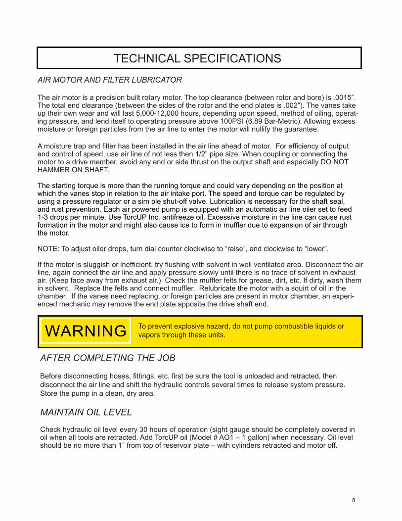
AIR MOTOR AND FILTER LUBRICATOR
The air motor is a precision built rotary motor. The top clearance (between rotor and bore) is .0015”. The total end clearance (between the sides of the rotor and the end plates is .002”). The vanes take up their own wear and will last 5,000-12,000 hours, depending upon speed, method of oiling, operat-ing pressure, and lend itself to operating pressure above 100PSI (6.89 Bar-Metric). Allowing excess moisture or foreign particles from the air line to enter the motor will nullify the guarantee.
A moisture trap and filter has been installed in the air line ahead of motor. For efficiency of output and control of speed, use air line of not less then 1/2” pipe size. When coupling or connecting the motor to a drive member, avoid any end or side thrust on the output shaft and especially DO NOT HAMMER ON SHAFT.
The starting torque is more than the running torque and could vary depending on the position at which the vanes stop in relation to the air intake port. The speed and torque can be regulated by using a pressure regulator or a sim ple shut-off valve. Lubrication is necessary for the shaft seal, and rust prevention. Each air powered pump is equipped with an automatic air line oiler set to feed 1-3 drops per minute. Use TorcUP Inc. antifreeze oil. Excessive mois ture in the line can cause rust formation in the motor and might also cause ice to form in muffler due to expansion of air through the motor.
NOTE: To adjust oiler drops, turn dial counter clockwise to “raise”, and clockwise to “lower”.
If the motor is sluggish or inefficient, try flushing with solvent in well ventilated area. Disconnect the air line, again connect the air line and apply pressure slowly until there is no trace of solvent in exhaust air. (Keep face away from exhaust air.) Check the muffler felts for grease, dirt, etc. If dirty, wash them in solvent. Replace the felts and connect muffler. Relubricate the motor with a squirt of oil in the chamber. If the vanes need replacing, or foreign particles are present in motor chamber, an experi-enced mechanic may remove the end plate apposite the drive shaft end.
TECHNICAL SPECIFICATIONS
To prevent explosive hazard, do not pump combustible liquids or vapors through these units.
AFTER COMPLETING THE JOB
Before disconnecting hoses, fittings, etc. first be sure the tool is unloaded and retracted, then disconnect the air line and shift the hydraulic controls several times to release system pressure. Store the pump in a clean, dry area.
MAINTAIN OIL LEVEL
Check hydraulic oil level every 30 hours of operation (sight gauge should be completely covered in oil when all tools are retracted. Add TorcUP oil (Model # AO1 – 1 gallon) when necessary. Oil level should be no more than 1” from top of reservoir plate – with cylinders retracted and motor off.
8

OPERATION PROCEDURES
PERIODIC MAINTENANCE
Completely change the hydraulic oil and clean the intake screen and magnet (located in the reservoir) twice a year. If equipped, change the external oil filter twice a year (Use TorcUP oil only, Model # AO1, 1 gallon). Change the oil more frequently when used in extremely dusty areas or when the oil has been overheated. Using oil other than TorcUP Brand may void the pump’s warranty.
The following conditions require more frequent oil changes. •Rigorous duty, where oil temperature may reach 150˚ F. •High humidity environment and extreme changes in temperature that can result in condensation inside the reservoir. •Dirty or dusty environments that may contaminate the oil. •Frequent connection and disconnection of hydraulic hoses and components.
CLEAN OIL INTAKE SCREEN ONCE A YEAR
Loosen and remove reservoir plate bolts. Lift pump unit off the reservoir, being careful not to damage the gasket.
Applies to 1.5, 2, 2.5 gallon reservoirs:Remove the five allen socket head cap screws, securing the screen to the 1st stage gear pump. Care should be taken not to remove the center plate and gears. Remove and clean with nonflammable solvent, blow dry clean. Reinstall in reverse order and torque bolts to 75 inch pounds. Keep the motor and pump as clean as possible.
Applies to the 5 and 10 gallon reservoirs:Unscrew screen from bottom of pump unit and clean with nonflammable solvent. Blow dry and reassemble. Keep areas around pump unobstructed to provide good air flow around the motor and pump. Keep the motor and pump as clean as possible.
FLUSH THE PUMP
If you suspect your pump has been contaminated or discover sludge or other deposits on internal components, you should thoroughly flush the pump. Remove the old oil from the reservoir, then thoroughly clean the reservoir and refill with a clean, nonflammable flushing oil. Reassemble the pump and motor to the reservoir.
Run the pump in no load condition for 1 or 2 minutes maximum. Unplug the pump and remove the motor and pump assembly again. Now drain the flushing oil and re-clean the inside of the reservoir. (Make sure flushing fluid is also drained from pump assembly). Reassemble the pump and refill the reservoir with TorcUP hydraulic oil and reassemble the pump.
9
PROBLEM CAUSE-SOLUTION Sporadic Tool Action: • Air in the hydraulic system. Bleed the hydraulic circuit. • Check reservoir oil level. Motor Will Not Start: • Too much water in air line, froze motor • Not enough air pressure • Have motor checked for proper operation. • Check air adjustment knob on FRL.Noisy Operation: • Air in system. • Be sure the oil reservoir is filled to normal level. • Check all points where air might leak into system. • Clogged or blocked intake screen. Pump Oil is Over Heating: • Inspect for high pressure leakage at the pump (leaking at plug or relief valve). • Oil level is low. Fill reservoir to normal level, or retrofit the pump with larger reservoir or heat exchanger. Pump Runs But Will Not Build Pressure: • Pump is not primed. Run pump a few minutes tipping from side to side. • Inspect to make sure that external adjustable relief valve is set properly. • Defective control valve, take to nearest TorcUP Authorized Service Center for repair. • Check to make sure the intake screen is not clogged. Clean if needed. • Check oil reservoir is low. Fill as needed. • Oil viscosity is too high. Replace with TorcUP oil. • Supplying air line too small • Not enough air pressure
TROUBLE SHOOTING
10

PARTS INDENTIFCATION
This illustration is for reference purposes only.The appearance of your unit may differ from the unit shown.
Valve Sub AssembliesPage 19-21
ManifoldSub-AssemblyPage 22
Pump Sub Assembliesand Sub-ComponentsPages 17-18
PendantsPage 23
Common ComponentsPage 13-15
ReservoirPage 24
11

How to Identify Parts for Your Model.
MODEL NUMBER & DATE CODE LOCATION
For example, the date code and serial numberJ = October07 = Year 200742 = Week number in year
J 07 42A B C D E F G H I J K L1 2 3 4 5 6 7 8 9 10 11 12
DATE CODE COVER PLATESTAMPING LOCATION
MODEL DECAL PLACEMENT
PARTS INDENTIFCATION
12

COMMON COMPONENTS
Note: This illustration is for reference only. The appearance of your unit may differ from unit shown.
4
90
3
45
6362
59
94
81
81
72
242
21
70
75
74
76
13
7521
20
19
15
83 84
88
98
78
91
87
97
96
82
86
9595
BLAC
K
YELL
OW
A
@ P
END
AN
TB
A
P
PB
AYE
LLO
W
BLAC
K
PB
7379
22
5857
STO
PRU
N
41
59
88
98
89
9215"
9215"
TORC
-UP
MO
DEL
#:
AP1
000
NO
TES:
TEST
PU
MP
FOR
FLO
W @
0, 5
,000
, 10,
000
PSI.
RECO
RD F
LOW
, RPM
, AN
D A
IR P
RESS
URE
.SE
T CR
OSS
OVE
R @
1,2
00-1
,300
PSI
.SE
T IN
TERN
AL
RELI
EF @
10,
200-
10,5
00 P
SI.
SET
RETR
ACT
RELI
EF @
1,7
00-1
,800
PSI
.
SHIP
PAC
KAG
ED O
IL W
ITH
PU
MP.
11
BEF
OR
E O
PER
ATIN
G P
UM
P:1.
Che
ck in
stru
ctio
n m
anua
l for
requ
ired
air s
uppl
y.2.
Use
dry
lubr
icat
ed a
ir. 1
00 P
SIG
max
imum
. A
ntifr
eeze
lubr
ican
t sho
uld
be u
sed
in o
iler a
nd m
uffle
r
to
prev
ent f
reez
e-up
.3.
Use
onl
y eq
uipm
ent r
ated
for 1
0,00
0 P
SI /
700
BA
R.
4. M
ake
sure
all
conn
ectio
ns a
re ti
ght,
secu
re a
nd k
ink-
free.
5. C
heck
the
rese
rvoi
r oil
leve
l. F
ill to
one
inch
of t
he to
p, if
nec
essa
ry.
6. N
ever
ope
rate
the
pum
p w
ithou
t too
l mov
emen
t for
mor
e th
an 1
min
ute
with
out s
hifti
ng th
e co
ntro
l
val
ve to
neu
tral.
Lea
ving
the
tool
in th
e ad
vanc
e or
retra
ct p
ositi
on w
ithou
t too
l mov
emen
t may
ove
rhea
t the
oil.
Do
not e
xcee
d oi
l ope
ratin
g te
mpe
ratu
res
of 1
40°
F or
60°
C.
AFT
ER C
OM
PLET
ING
TH
E JO
B:
1. B
efor
e di
scon
nect
ing
your
equ
ipm
ent,
first
be
sure
the
tool
is u
nloa
ded,
then
unp
lug
the
pow
er c
ord
a
nd s
hift
the
hydr
aulic
con
trols
sev
eral
tim
es to
rele
ase
syst
em p
ress
ure.
2. S
tore
the
pum
p in
a c
lean
, dry
pla
ce.
PER
IOD
IC M
AIN
TEN
AN
CE:
1. C
hang
e th
e hy
drau
lic o
il an
d cl
ean
the
oil s
cree
n, b
reat
her a
nd m
agne
t (lo
cate
d in
the
rese
rvoi
r) tw
ice
a
yea
r. R
efer
to th
e op
erat
ing
inst
ruct
ions
for d
etai
ls.
Whe
n us
ed in
ext
rem
ely
dust
y ar
eas
or o
il ha
s be
en
o
verh
eate
d, c
hang
e th
e oi
l mor
e fre
quen
tly.
683
94
AIR
PU
MP
INST
RU
CTI
ON
S FO
R S
AFE
OPE
RAT
ION
REVI
EW A
LL O
PERA
TIN
G
INST
RUC
TIO
NS
SKIN
PU
NC
TURE
/H
YDRA
ULI
C LI
NE
10,0
00 P
SI/
700
BAR
52 6
APP
LY L
OC
TITE
243
1227
71 16
14
7
5
INST
ALL
SH
IPPI
NG
PLU
G
8714
5 A
ND
SH
IP B
REAT
HER
VE
NT
4634
8 IN
A B
AG F
OR
CUST
OM
ER T
O IN
STA
LL
17
P A
B
A
B
P
SHU
TTLE
VALV
E
SHU
TTLE
VA
LVE
MO
TOR
FILT
ER/L
UBR
ICAT
OR
P
B
ASS
EMBL
Y N
OTE
S:
TO
RQU
E TO
225
-275
IN*L
BS T
ORQ
UE
TO 4
5-55
IN*L
BS T
ORQ
UE
TO 1
8-22
IN*L
BS T
ORQ
UE
TO 6
8-82
IN*L
BS A
PPLY
TEF
LON
TAPE
& T
ORQ
UE
TO 3
2-39
FT*
LBS
APP
LY T
EFLO
N TA
PE &
TO
RQU
E TO
80-
100
IN*L
BS A
PPLY
TEF
LON
TAPE
& T
ORQ
UE
TO 2
0-25
FT*
LBS
AD
D 5
-10
DRO
PS O
F PN
EMAT
IC O
IL IN
FIT
TIN
G #
81
BEF
ORE
INST
ALL
ING
INTO
MO
TOR
APP
LY L
OC
TITE
243
& T
ORQ
UE
TO 6
0-72
IN*L
BS
AIR
CO
NTR
OL
VALV
E #8
2PA
RT #
DS2
2849
00
PEN
DA
NT
AN
D H
OSE
#'S
41
& 8
9 PA
RT #
'S 6
8799
& 4
1965
1
1
11
1
2
3
4
4
2
2
2
2
5
5
6 6
66
3 41 2 75 6
7
7
7
7
7
5
8
8
9
9
13

COMMON COMPONENTS
Balloon # Item Description Quantity UOM0 18131 HYDRAULIC OIL 1 QT. 2 EA0 AO1 HYD OIL-1 GAL. 1 EA2 46335SS PUMP ASM. G5 2 STAGE 1 EA3 45996P RESERVOIR 1.5 GAL. BLACK 1 EA4 * RESERVOIR GASKET 1 EA5 46348 BREATHER VENT 3/8 NPT 1 EA6 46697 1/2 FLUSH PLUG W/SEALANT 1 EA7 46118 SAE #12 HEX PLUG WITH PORT 1 EA8 65891 1/4-20 X .75 HHCS ZINC 14 EA9 65892 SEALING WASHER 14 EA11 68394 SAFE USE DECAL AIR 1 EA12 87305 BLANK DECAL 3 X 4 2 EA13 46292SS MANIFOLD ASM. TORQUE WRENCH 1 EA14 * VALVE GASKET 1 EA15 99921 SHCS 3/8-16 X 2 3/4 3 EA16 68963SS ADAPTER ASSY. 1 EA17 87145 PLUG 1 EA19 46297SS AIR SOLENOID 4W/2P NORMALLY RETRACT 1 EA20 88363 SHCS 3/8-16 X 3 1/2 4 EA21 93943 LOCK WASHER 6 EA22 561604 SPRING PIN 1 EA24 * MAGNET 1 EA27 46539 DECAL OVERLAY 1 EA41 68799SS PENDANT AIR TORQ WRE 1 EA45 6001768 HANDLE 1 EA52 46009 SIGHT GAUGE 1 EA57 4100067 1/4” NIPPLE 1 EA58 CT210 1/4"NIPPLE 1 EA59 45765 1/4"SELF-LOCKING COUPLER 2 EA62 6001769 HHCS .25-28x 1.25 ZINC 2 EA63 6001770 FLAT WASHER M6 2 EA70 * GASKET-MOTOR 2 EA71 * PUMP GASKET G5 1 EA72 86244 STREET ELBOW 1 EA73 46334 COVER PLATE G5 TORQUE WRENCH 1 EA74 6001771 DOWEL PIN 3/16" x 2" LONG 1 EA
14

COMMON COMPONENTS
Balloon # Item Description Quantity UOM75 97084 SHCS 3/8-16 X 3/4 LG 4 EA76 86447B AIR MOTOR 6AM PAINTED BLACK 1 EA78 46279 FHCS 1/4-28 x 0.50 LONG 4 EA79 46392 MOTOR STANDOFF 1 EA81 86243 ELBOW MALE 1/2 NPT PIPE 2 EA82 DS2284900SS AIR CONTROL VALVE ASSEMBLY 1 EA83 45970 MALE HEX NIPPLE 1/4 - 1/8 1 EA84 44245 SHUTTLE VALVE 1 EA86 DS2209111 BRACKET FILTER/LUBRICATOR 1 EA87 6001772 HOSE BARB TO MALE PIPE 1 EA88 87283 HOSE CLAMP 2 EA89 41965 HOSE-EA. 1 EA90 DS2279118 FILTER REGULATOR LUBRICATOR 3/8" NPT 1 EA91 69645R HOSE- PUSH LOK 12 IN92 S69361 NYLON TUBING 30 IN94 6001773 MUFFLER PARKER ZA4 1 EA95 68794 MALE ELBOW 1/4 TUBE 2 EA96 93581 SHCS 1/4-20 X 1/2 2 EA97 93849 HEX NUT (.250-20) 2 EA98 DS2280662 VALVE FLOW CONT 3/8" NPT 1 EA* 54488 REBUILD KIT
15

(46335SS) PUMP ASM.
1
24
3 4
56 778
910
15
16
18
20
213924
23
22
25
25
25
25
25
25
25
3332 31
3231
32
30
35
36
37
38
41
46
47
34
28 27
44
1114
19
50
50
4949
17
12
12
1312
44 45 44
29
4348
50 50
SEC
TIO
N B
-B
BB
TORQ
UE
TO90
IN*L
BS.
TORQ
UE
TO12
0 IN
*LBS
.
TORQ
UE
TO25
IN*L
BS.
TORQ
UE
TO90
IN*L
BS.
TORQ
UE
TO90
IN*L
BS.
TORQ
UE
TO90
IN*L
BS.
TORQ
UE
TO90
IN*L
BS.
TORQ
UE
TO12
0 IN
*LBS
.
TORQ
UE
TO35
0 IN
*LBS
.
TORQ
UE
TO35
0 IN
*LBS
.
TORQ
UE
TO35
0 IN
*LBS
.
TORQ
UE
TO90
IN*L
BS.
TORQ
UE
TO90
IN*L
BS.
TORQ
UE
TO17
5 IN
*LBS
.
TORQ
UE
TO17
5 IN
*LBS
. TORQ
UE
TO75
IN*L
BS.
TORQ
UE
TO75
IN*L
BS.
TORQ
UE
TO75
IN*L
BS.
TORQ
UE
TO17
5 IN
*LBS
.
TORQ
UE
TO17
5 IN
*LBS
.
TORQ
UE
TO
130
IN*L
BS
TORQ
UE
TO
130
IN*L
BS
TORQ
UE
TO
130
IN*L
BS
TORQ
UE
TO
130
IN*L
BS
PUMP ASSEMBLY
16

(46335SS) PUMP ASM.ITEM # DESCRIPTION PART # QTY
1 PUMP BODY 45750 12 BEARING ROLLER 5/8x13/16x5/8 WIDE 68360 13 THRUST BEARING 66033 14 THRUST WASHER 66474 25 ECCENTRIC SHAFT ASM 5/8" 45820SS 16 THRUST BEARING 66106 17 THRUST WASHER 66108 28 ECCENTRIC SHAFT ADAPTER 45908 19 O-RING 1 3/4 X 1 7/8 5602031 110 RETAINING RING 68978 111 POW'R BUD DUMP PLUG 43283 112 O-RING 3/16X5/16 5602008 313 BACKUP WASHER 56080087 114 MALE TEE 1/8" PIPE TO 1/4" TUBE 45426 115 PIPE PLUG 1/4" FLUSH W/ COATING 46509 116 UNLOADING PISTON ASSEMBLY 43766SS 217 MALE ELBOW 1/4" TUBE 1/4" PIPE 45929 118 BALL 1/8" 90906 219 PISTON BLOCK TUBE 46548 120 OUTLET TUBE PISTON BLOCK 45815 121 BALL 5/16" 91701 322 UNLOADING SPRING 43671 123 ADJUSTING SCREW 45903 124 O-RING 5/8X3/4 URETH 56020162 125 PIPE PLUG FLUSH 1/16 W/ COATING 40049 727 BOTTOM PLATE 45900 1
29 SHAFT-IDLER 68850 130 SCREEN 68921 131 TUBE-GUIDE .11 68894 232 SHCS 1/4-28 X 1 3/4 68255 533 PLATE-SCREEN MTG. 68927 134 MALE ELBOW 1/8 PIPE 69354 135 SPRING 68225 236 ROLL PIN 1/8 X 3/4 LONG 97782 137 BALL STOP 45904 238 GASKET 29/64 X 5/8 86269 239 SPRING CAP UNLOADING VALVE 43673 141 TUBE RETURN 68569 143 BEARING ROLLER 1 1/4x1 1/2x3/4 WIDE 66030 144 BEARING ROLLER 1/2x11/16x1/2 WIDE 68891 345 RING-RETAINING 68892 146 PIPE PLUG 1/8" FLUSH W/ COATING 46508 147 CART REL. VAL. ASSEMBLY 66220SS 148 SHAFT SEAL 45930 149 PISTON BLOCK ASM. 0.255" 46336SS 250 SHCS 5/16-24 X 1.75 69392 8
28 GEAR SET 9/33” 45823S 1
PUMP ASSEMBLY
17

ITEM # DESCRITPION PART # QTY.01 UNLOAD PISTON 43765 1.0002 O RING 1/4X3/8 1.0003 BACK-UP WASHER TEF 43768 1.0004 DOWEL PIN 1/8X3/4 LG 43686 1.00
5602009
1
11
12
7
10
8
9
6
5
2
4
3
2
TORQUE TO 25 IN*LBS.
TORQUE TO 150 IN*LBS.
TORQUE TO 400 IN*LBS.
TORQUE TO 200 IN*LBS.
PART# 46336SS (PISTON BLK ASM. )
ITEM # DESCRIPTION PART # QTY1 PISTON BLOCK 45539 12 BALL 1/8" 90906 23 SPRING 66042 14 BALL STOP 68810 15 BALL RETAINER 66043 16 INTAKE SEAT 66046 17 GASKET 25/64X19/32 85726 18 PLUG PISTON BLOCK 68825 19 GASKET 29/64 X 5/8 86269 110 ADAPTOR .255 DIA. 68909 111 SPRING, PISTON 68340 112 PISTON .255 DIA. 68222 1
PART# 43766SS (UNLOADING PISTON ASM.)PUMP ASM.
PART# 46336SS (PISTON BLK ASM)
PUMP SUB ASSEMBLY
18

ITEM# DESCRIPTION PART # QTY1 BODY-VALVE 68708 12 SLIDER ADV/RET ONLY 44328 13 BALL 3/16" 90548 44 SET SCREW 1/4-28 X 1/4 CUP 40254 45 AIR CYL ASM 41954SS 16 O-RING 7/32X11/32 5602009 37 BACK UP WASHER 68391 38 SHEAR SEAL 68383 39 SPRING 68384 310 O-RING 2 5/8 X 2 3/4 5602038 111 BEARING ROLLER 5/16x1/2x5/16 WIDE 68385 412 PIN BEARING 68390 213 SET SCREW 5/16-18 X 1/4 CUP 94418 114 SHCS #10-32 X 1" LG PLATED 68264 215 VALVE TOP PLATE MACHINED 46272 116 SHCS #10-24 X 3.25" 41959 417 O-RING 3/16X5/16 5602008 118 BALL 1/4" 92549 119 VALVE PLUG 2 POSITION SLIDER 46271 126 O-RING SAE PORT #10 5603910 127 SPRING 68711 129 SPACER VALVE SLIDER 46418 131 O-RING 5/16X7/16 URE 56020112 4
PART#46297SS (AIR SOLENOID 4W/2P)
15
14
10
2
4
3
1
98
1211
13
17
HYDRAULICSCHEMATIC
29
19
4 PLACES
4 PLACES
76
5
16
P T
A B
P T
A B
26
27
TORQUE TO 50 IN*LBS.
TORQUE TO25 IN*LBS.
TORQUE TO84-108 IN*LBS.
TORQUE TO 150 IN*LBS.
TORQUE TO 75 IN*LBS.
TORQUE TO50 IN*LBS.
31
18
PART# 46297SS (AIR SOLENOID 4W/2P)
VALVE ASSEMBLY
19

VALVE SUB ASSEMBLY
ITEM# DESCRIPTION PART# QTY.1 VALVE ADP 88073 12 B-U RING 65881 23 O-RING 3/8X1/2 5602012 2
1
23PART# 41954SS (AIR CYL ASSM )
ITEM # DESCRIPTION PART # QTY1 BODY AIR CYL 42744 12 O-RING 1/8 X 1/4 5602006 13 O RING 1/4X3/8 5602010 14 AIR CYLINDER PISTON 42747 15 SPRING AIR CYL 42749 17 END CAP 41956 18 O-RING 1 1/16X1 3/16 5602023 19 SEAL 68497 110 O-RING 11/16X13/16 5602017 111 O-RING SAE PORT #10 5603910 112 PUSH PIN AIR VALVE 42746 113 OVERRIDE PIN 41958 114 E-RING 1/4" SHAFT 42750 115 SPRING PLATE AIR VLV 42748 1
PART# 68963SS (VALVE ADPT)
20

1
3
4
1
2
1 1
2
3
3
31
4
4
104101 108
102
103
106
107
100
105
107
106
TORQUE NOTES:
APPLY TEFLON TAPE & TORQUE TO 20-25 FT*LBS TORQUE TO 20-25 FT*LBS APPLY TEFLON TAPE & TORQUE TO 80-100 IN*LBS TORQUE TO 45-55 IN*LBS
Balloon # Item Description Quantity UOM100 45969 AIR CONTROL VALVE 1/2 PORTS 1 EA101 6011456 FITTING SWIVEL ELBOW 1/2 NPT 1 EA102 42381 SWIVEL ADP 1/8 1 EA103 42377 PIPE ADP 1/2-1/8 1 EA104 42378 STREET TEE 1/2" NPT 1 EA105 45991 HOSE BARB ELBOW 1/2 NPT TO 1/2 TUBE 1 EA106 42968 1/8 SWIVEL TEE 2 EA107 69362 SWIVEL NUT ELBOW 2 EA108 46697 1/2 FLUSH PLUG W /SEALANT 1 EA
PART# 46544SS (AIR CONTROL VALVE ASSM.)
VALVE SUB ASSEMBLY
21

MANIFOLD ASSEMBLY
ITEM # DESCRIPTION PART # QTY.01 VALVE MANIFOLD 46270 1.0002 CARTRIDGE RELIEF VALVE 45423 1.0003 1/16 PIPE PLUG-FLUSH 40049 3.0004 PIPE PLUG 1/8" FLUSH 81093 3.0005 PIPE NIPPLE 1/8 NPT 68917 1.0006 PIPE COUPLING 1/8 68918 1.0007 INT.RELIEF ASM HF 68999SS 1.00
(68999SS) INT. RELIEF ASM.
ITEM # DESCRIPTION PART # QTY.01 CARTRIDGE 66096 1.0002 CONE REL VLVE 66086 1.0003 POPPET RELIEF SPRING 44641 1.0004 RELIEF VALVE ADJUSTING SCREW 66083 1.0005 HEX NUT 7/16-20 68920 1.00
PART# 46292SS MANIFOLD ASM.
PART# 68999SS INT. RELIEF ASM.
22

PART# 68799SS (PENDANT ASSM.)
ITEM# DESCRIPTION PART # QTY1 PENDANT BODY 41968 12 AIR PEND. BLOCK MOD. 68796 13 CARTRIDGE-AIR 41963 24 SWIVEL ADP 1/8 42381 35 BALL 5/32 6069613 36 RETAINING-RING 68808 27 CARTRIDGE CAP 41970 2
PENDANT ASSEMBLY
23
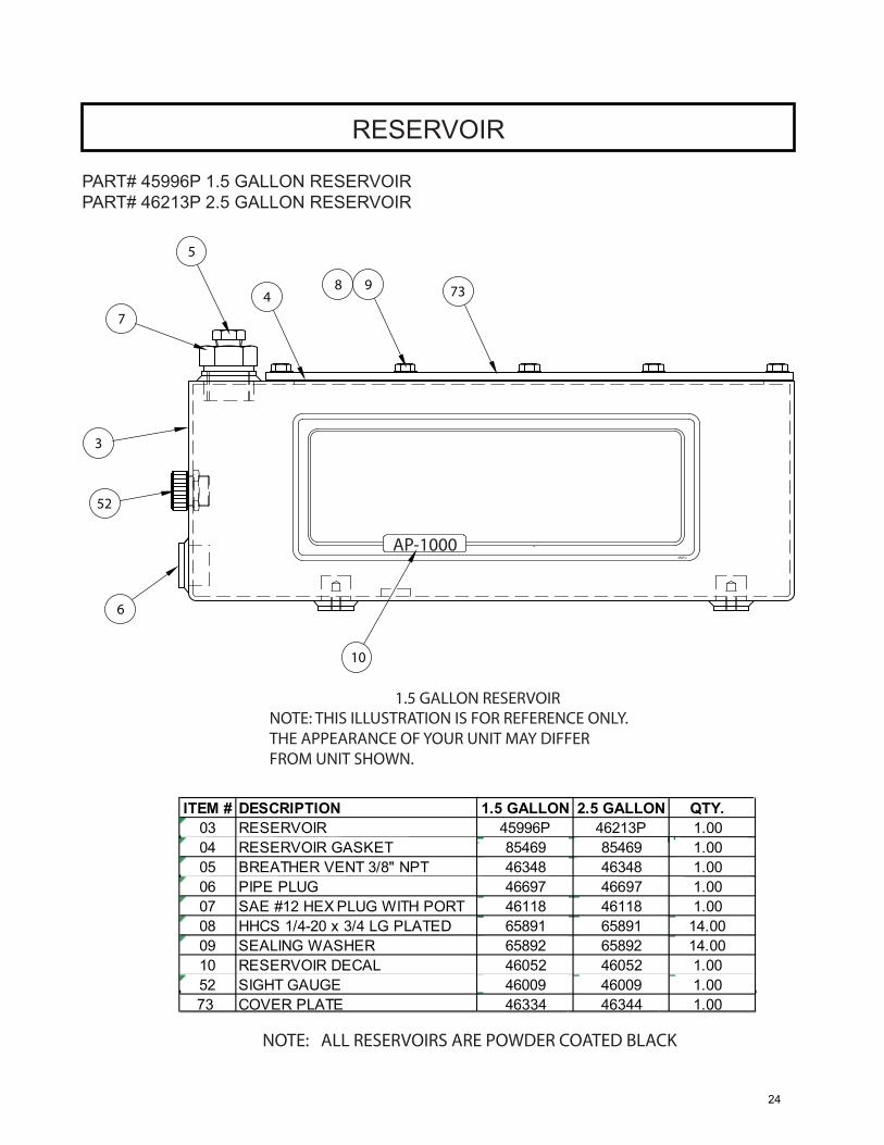
RESERVOIR
Reservoirs AP-1000 Torque WrenchPower Pump
(46213P) 2.5 GALLON RESERVIOR(45996P) 1.5 GALLON RESERVIOR
NOTE: ALL RESERVOIRS ARE POWDER COATED BLACK
NOTE: THIS ILLUSTRATION IS FOR REFERENCE ONLY.THE APPEARANCE OF YOUR UNIT MAY DIFFER FROM UNIT SHOWN.
1.5 GALLON RESERVOIR
ITEM # DESCRIPTION 1.5 GALLON 2.5 GALLON QTY.03 RESERVOIR 45996P 46213P 1.0004 RESERVOIR GASKET 85469 85469 1.0005 BREATHER VENT 3/8" NPT 46348 46348 1.0006 PIPE PLUG 46697 46697 1.0007 SAE #12 HEX PLUG WITH PORT 46118 46118 1.0008 HHCS 1/4-20 x 3/4 LG PLATED 65891 65891 14.0009 SEALING WASHER 65892 65892 14.0010 RESERVOIR DECAL 46052 46052 1.0052 SIGHT GAUGE 46009 46009 1.0073 COVER PLATE 46334 46344 1.00
10
6
1,1 Kw1 hp1/2
46052
3
52
98 73
5
74
AP-1000
PART# 45996P 1.5 GALLON RESERVOIRPART# 46213P 2.5 GALLON RESERVOIR
24

SAVE THESE INSTRUCTIONS DO NOT DESTROY
NOTES:
1025 Conroy Place, Easton PA 18040 * U.S.A.Phone: +1 610-250-5800 * Fax:+1 610-250-2700
Toll Free: 1-888-TORCUP-1Email: [email protected] * Website: www.torcup.com
25