
MANUAL - TorcUP Inc. · Operational and Maintenance Manual for TorcUP SQ-1, SQ-3, SQ-5 & SQ-10 ......
28
OPERATION AND MAINTENANCE MODELS SQ-1, SQ-3, SQ-5 & SQ-10 MANUAL SQ Series Uni-Swivel Square Drive Hydraulic Torque Wrenches SQ Series Phone: +1 610-250-5800 Fax: +1 610-250-2700 Toll Free: 1-888-TORCUP-1 Email: [email protected] Website: www.torcup.com 1025 Conroy Place, Easton, PA. 18040 U.S.A.
Transcript of MANUAL - TorcUP Inc. · Operational and Maintenance Manual for TorcUP SQ-1, SQ-3, SQ-5 & SQ-10 ......

OPERATION AND MAINTENANCE
MODELS SQ-1, SQ-3, SQ-5 & SQ-10
MANUALSQ Series Uni-Swivel Square Drive Hydraulic Torque Wrenches
SQ Series
Phone: +1 610-250-5800 Fax: +1 610-250-2700
Toll Free: 1-888-TORCUP-1Email: [email protected] Website: www.torcup.com1025 Conroy Place, Easton, PA. 18040 U.S.A.

1
Operational and Maintenance Manual for TorcUP SQ-1, SQ-3, SQ-5 & SQ-10
Single Swivel Square Drive Hydraulic Torque WrenchesVersion 2: 2016 September
Series SQ-1, SQ-3, SQ-5 & SQ-10 SQ Series Uni-Swivel Square Drive Hydraulic Torque Wrenches are designed for installing and removing threaded fasteners requiring precise high torque during bolt
makeup and maximum torque during bolt breakout.
TorcUP Inc. is not responsible for customer modification of tools for applications on which TorcUP Inc. was not consulted.
IMPORTANT SAFETY INFORMATION ENCLOSED.READ THIS MANUAL BEFORE OPERATING TOOL.
IT IS THE RESPONSIBILITY OF THE EMPLOYER TO PLACE THE INFORMATION IN THIS MANUAL INTO THE HANDS OF THE OPERATOR.
FAILURE TO OBSERVE THE FOLLOWING WARNINGS COULD RESULT IN INJURY.
USING THE TOOL
• Always operate, inspect and maintain this tool in accordance with American National Standards Safety Code for Hydraulic Rams and Jacks (ANSI B30.1).
• This tool will function using an air or electric powered hydraulic pump. Adhere to the pump safety requirements and follow instructions when connecting the pump to the tool.
• Use only equipment rated for the same pressure and torque.• Use only a hydraulic pump capable of generating 10,000 psi (681 bar) maximum pressure with this
tool.• Use only twin line hydraulic hose rated for 10,000 psi (681 bar) pressure with this tool.• Do not interchange the male and female swivel inlets on the tool or the connections on one end of
the hose. Reversing the inlets will reverse the power stroke cycle and may damage the tool.• Do not use damaged, frayed or deteriorated hoses and fittings. Make certain there are no cracks,
splits or leaks in the hoses.• Use the quick connect system to attach the hoses to the tool and pump.• When connecting hoses that have not been preloaded with hydraulic oil, make certain the pump
reservoir is not drained of oil during start-up.• Do not remove any labels. Replace any damaged label.• Do not handle pressurized hoses. Escaping oil under pressure can penetrate the skin, causing
serious injury. If oil is injected under the skin, see a doctor immediately.• Never pressurize uncoupled couplers. Only use hydraulic equipment in a coupled system.• Always wear eye protection when operating or performing maintenance on this tool.• Always wear head and hand protection and protective clothing when operating this tool.
NOTICE
WARNING
For Technical Support & Information Contact:TorcUP Inc.
1025 Conroy Place, Easton, PA 18040 USAPhone: +1 610-250-5800 Fax:+1 610-250-2700
email: [email protected]
The use of other than genuine TorcUP replacement parts may result in safety hazards, decreased tool performance, increased maintenance, and may invalidate
all warranties. Repairs should be made only by authorized personnel. Consult your nearest TorcUP Authorized Service Center.
Refer All Communications to the Nearest TorcUP Office or Distributor.

2
FAILURE TO OBSERVE THE FOLLOWING WARNINGS COULD RESULT IN INJURY
Do NOT Exceed Maximum Pressure. See Torque Chart with Tool. Damage May Occur.
Always wear eyeprotection when operating orperforming maintenance on this tool.
Always wear ear protection when operating this tool.
Do not carry the toolby the hose.
Keep body stance balanced and firm. Do not overreachwhen operating this tool.
USING THE TOOL
• Keep hands, loose clothing and long hair away from the reaction arm and working area during operation. • This tool will exert a strong reaction force. Use proper mechanical support and correct reaction arm
positioning to control these forces. Do not position the reaction arm so that it tilts the tool off the axis of the bolt and never use the swivel inlets as a reaction stop.
• Avoid sharp bends and kinks that will cause severe back-up pressure in hoses and lead to premature hose failure.
• Use accessories recommended by TorcUP. • Use only impact sockets and accessories. Do not use hand (chrome) sockets or accessories.• Use only sockets and accessories that correctly fit the bolt or nut and function without tilting the tool off the
axis of the bolt.• This tool is not insulated against electric shock. • This equipment must not be operated or serviced unless the operator read the operating instructions and
fully understands the purpose, consequences and procedure of each step.• When operating a larger tool above waist height, employ a secondary means of support for safety
purposes. A tool sling or chains may be used. Consult your safety department for further suggestions.
Depending on the working environment your local health and safety regulations may require you wear protective gear (i.e. safety shoes, hard hat, gloves, coveralls, etc.). In case external forces are exerted on the equipment, non-compliance with these regulations may result in injury. EAR PROTECTION MUST BE WORN WHEN OPERATING THIS TOOL.
The Torque Reaction Arm must be positioned against a positive stop. Do not use the arm as a dead handle. Take all precautions to make certain the operator’s hand cannot be pinched between thearm and a solid object.
Do not use damaged, frayed or deteriorated hydraulic hoses and fittings.
WARNING

3
PLACING THE TOOL IN SERVICE
CONNECTING THE TOOL
1. Attach the twin line hose to the swivel inlets of the square drive torque wrench using the spring–loaded quick connect ends.
2. Connect the opposite ends of the hose to the pump in the same manner.
ADJUSTMENTS
SETTING THE SQUARE DRIVE FOR ROTATION
The position of the square drive when looking toward the shroud will determine if the tool is set to tighten or loosen the nut. When the square drive extends to the left when looking at the shroud with the swivels away from you, the tool is set to loosen the nut. When the square drive extends to the right, the tool is set to tighten the nut. To change the direction of rotation for models SQ-1 SQ-3, and SQ-10 simply push the square drive into the housing until the drive projects out the opposite side of the tool. For the model SQ-5, loosen and remove the square drive retaining knob, and pull the square drive out of the housing. Insert the square drive into the opposite side of the housing, and secure it by installing the knob in the splined end of the drive.
SETTING THE TORQUE
After determining the desired torque, use the calibration certificate provided with the tool to determine the pressure necessary to achieve that torque. You may also refer to the chart engraved on the shroud of the tool or the chart provided on pages 8-11 of this manual.
1. Connect the tool to the power supply and turn the pump on.
2. Depress the remote control button causing the pressure to be shown on the gauge.
3. Adjust the pressure by loosening the wing nut that locks the pressure adjustment thumb screw. Rotate the thumbscrew clockwise to increase the pressure and counterclockwise to decrease the pressure. When decreasing pressure, always lower the pressure below the desired point and then bring the gauge back up to the desired pressure.
4. When the desired pressure is reached, retighten the wing nut and cycle the tool again to confirm that the desired pressure setting has been obtained.

4
The function of a reaction device is to hold the tool in position against the forces generated to tighten or loosen bolts or nuts. Hydraulic wrenches generate tremendous force.
SETTING THE REACTION ARM
An improperly positioned reactionarm may result in operator injuryor damage to tooling.
Square Drive Hydraulic Wrench Reaction Points (Dwg.01)
Make sure the reaction arm is positioned correctly. (Refer to Dwg. 01).
The reaction arm can be positioned numerous places within a 360O circle. However, for the arm to be correctly positioned, it must be set within a 90O quadrant of that circle. That quadrant is the area located between the protruding square drive and the bottom of the housing away from the swivel inlets. It will always be toward the lower half of the housing and on one side of the housing when tightening and on the other side when loosening.(Dwg. 01)

5
OPERATING THE WRENCH
The position of the square drive relative to the shroud determines whether the action will tighten or loosen thenut. (Refer to Dwg. 02 for application examples).The power stroke of the piston assembly will always turn the square drive toward the shroud.
1. Insert the square drive into the mating socket. Then, insert the safety pin through the socket, and seat the included O-ring into the groove to capture the pin. Place the socket onto the nut making sure the socket is the proper size and that all mating parts are fully seated.
2. Position the reaction arm or surface against an adjacent nut, flange or solid system component. Make certain that there is clearance for the hoses, swivels, inlets and end plug. DO NOT allow the tool to react against the hoses, swivels, inlets or end plug.
3. After turning the pump on and presetting the pressure for the correct torque, depress the remote control button to advance the piston assembly.
4. When the wrench is started, the reaction surface of the wrench or reaction arm will move against the contact point, and the nut will begin to turn.
5. When the nut is no longer turning and the pump gauge reaches the preset pressure, release the remote control button. The piston rod will retract when the button is released, and under normal conditions, an audible “click” will be heard as the tool resets itself.
6. Continue to cycle the tool until it “stalls” and the preset psi/torque has been attained.
7. Cycle the tool one additional time to ensure full torque.
Square Drive Position for Loosening and Tightening(Dwg.02)
Drawing 02

6
MARINE MOLY GREASE
Lubrication frequency is dependent on factors known only to the user. The amount of contaminants in the work area is one factor. Tools used in a clean room environment will obviously require less service than a tool used outdoors and dropped in loose dirt or sand. Marine Moly Grease is formulated not to wash out of the tool in areas where lubrication is critical.
Whenever lubrication is required, lubricate as follows:
1. Remove the drive plate, ratchet, drive segment and sleeves as instructed in the maintenance section, and wash the components in a suitable cleaning solution in a well ventilated area.
2. After drying the components, wipe a film of Marine Moly Grease onto the wear surface of both sleeves and the ends of the ratchet.
3. Spread a light film of Marine Moly Grease onto the inner face and both sides of the drive plate. Do not pack the teeth of the drive segment or ratchet with lubricant. It can prevent the teeth from engaging properly.
4. Place a daub of Marine Moly Grease in the piston rod recess of the drive plate before linking the piston rod to the drive plate at assembly.
CRITICAL LUBRICATION
It is imperative to lubricate the piston rod recess of the drive plate to piston rod contact area every 80 hours of continuous duty cycling.
Lubricate as follows:
1. Remove shroud screws, shroud, and roll pin.
2. Pry the drive plate assembly forward from the piston rod to expose the recessed contact area in the drive plate.
3. With a rag, wipe clean the area, and apply a sizeable amount of Marine Moly Grease.
4. Reassemble as instructed in the maintenance section.
LUBRICATION

7
SQ Series Uni-Swivel Wrench Technical & Dimensional Data
Model Number SQ-1 SQ-3 SQ-5 SQ-10Square drive 3/4” 1” 1 1/2” 1 1/2”Min. Torque (ft/lbs) 156 379 507 956Max. Torque (ft/lbs) 1414 3515 5523 10620Min. Torque (nm) 212 515 690 1300Max. Torque (nm) 1923 4780 7511 14443Output Accuracy +/-3% +/-3% +/-3% +/-3%Repeatability 100% 100% 100% 100%Duty Cycle 100% 100% 100% 100%Tool Weight (lbs/kg) 5.5/2.5 11.0/5.0 18.5/8.4 32.0/14.5Height (in/mm) 3.76/95.5 4.91/124.7 6.05/153.6 7.34/186.4Length 1 (in/mm) 4.91/124.7 6.48/164.5 7.95/201.9 9.85/250.1Length 2 (in/mm) 6.47/164.3 8.48/215.3 10.70/271.7 2.85/326.3Radius (in/mm) 0.99/25.1 1.31/33.2 1.57/39.8 2.13/54.1Width 1 (in/mm) 2.00/50.8 2.63/66.8 3.13/79.5 3.95/100.3Width 2 (in/mm) 2.75/69.8 3.68/93.5 4.64/117.8 5.47/138.9Width 3 (in/mm) 4.61/117.0 5.92/150.3 7.00/117.8 8.74/222.0

8

9

10

11
................ ,un�ur SQ-10 Torque Conversion Chart
Imperial Conversion Metric Conversion PSI ft-lb Bar Nm
1,000 945 69 1281 1,200 1150 83 1559 1,400 1354 97 1836 1,600 1559 110 2114 1,800 1763 124 2390 2,000 1968 138 2668 2,200 2179 152 2954 2,400 2389 165 3239 2,600 2600 179 3525 2,800 2810 193 3810 3,000 3021 207 4096 3,200 3234 221 4385 3,400 3446 234 4672 3,600 3659 248 4961 3,800 3871 262 5248 4,000 4084 276 5537 4,200 4300 290 5830 4,400 4517 303 6124 4,600 4733 317 6417 4,800 4950 331 6711 5,000 5166 345 7004 5,200 5382 359 7297 5,400 5599 372 7591 5,600 5815 386 7884 5,800 6032 400 8178 6,000 6248 414 8471 6,200 6466 427 8767 6,400 6684 441 9062 6,600 6901 455 9356 6,800 7119 469 9652 7,000 7337 483 9948 7,200 7560 496 10250 7,400 7783 510 10552 7,600 8006 524 10855 7,800 8229 538 11157 8,000 8452 552 11459 8,200 8673 565 11759 8,400 8894 579 12059 8,600 9114 593 12357 8,800 9335 607 12657 9,000 9556 621 12956 9,200 9775 634 13253 9,400 9994 648 13550 9,600 10212 662 13846 9,800 10431 676 14143 10,000 10650 689 14439 .. For reference purposes only, please consult the calibration chart spec1f1c to your purchase or rental tool.
TorcUP, Inc. 1025 Conroy Place Easton, Pa 18040 ACC R EDITED
Tel:610-250-5800 Fax: 610-250-2700 Mbi#ififf
12
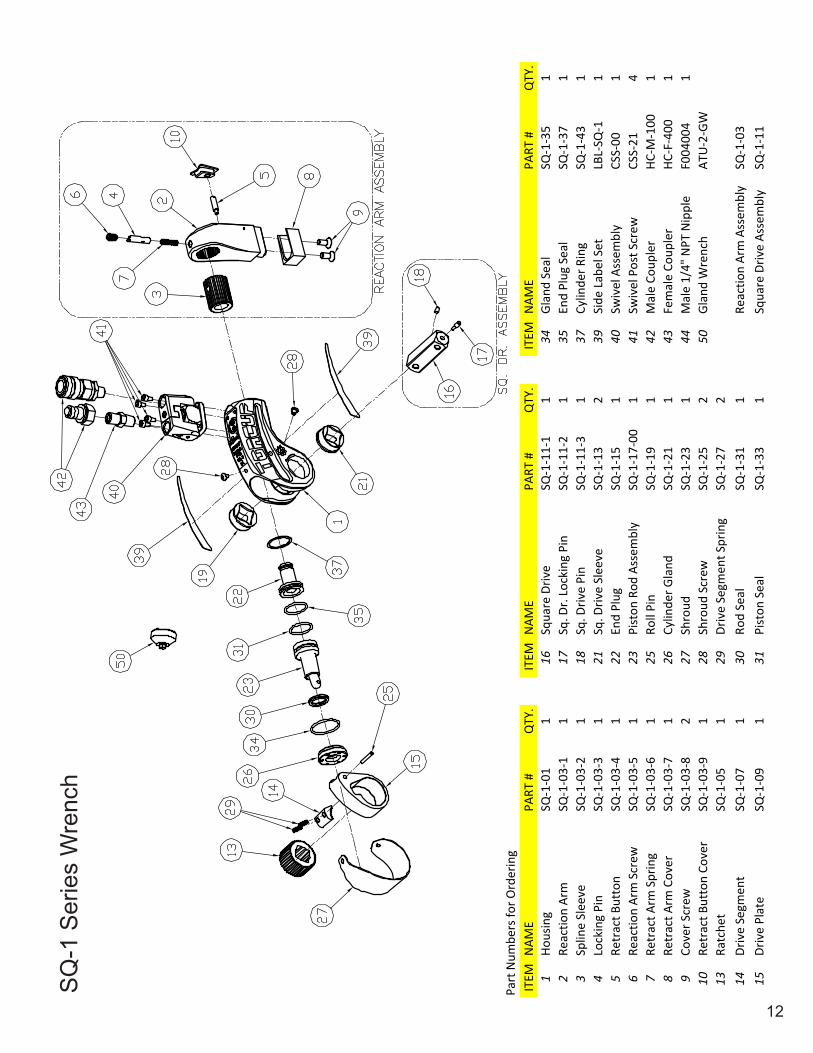
SQ
-1 S
erie
s W
renc
h
ITEM
NAM
EPA
RT #
QTY
.IT
EMN
AME
PART
#Q
TY.
ITEM
NAM
EPA
RT #
QTY
.1
Hous
ing
SQ-1
-01
116
Squa
re D
rive
SQ-1
-11-
11
34Gl
and
Seal
SQ-1
-35
12
Reac
tion
Arm
SQ-1
-03-
11
17Sq
. Dr.
Lock
ing
Pin
SQ-1
-11-
21
35En
d Pl
ug S
eal
SQ-1
-37
13
Splin
e Sl
eeve
SQ-1
-03-
21
18Sq
. Driv
e Pi
nSQ
-1-1
1-3
137
Cylin
der R
ing
SQ-1
-43
14
Lock
ing
Pin
SQ-1
-03-
31
21Sq
. Driv
e Sl
eeve
SQ-1
-13
239
Side
Lab
el S
etLB
L-SQ
-11
5Re
trac
t But
ton
SQ-1
-03-
41
22En
d Pl
ugSQ
-1-1
51
40Sw
ivel
Ass
embl
yCS
S-00
16
Reac
tion
Arm
Scr
ewSQ
-1-0
3-5
123
Pist
on R
od A
ssem
bly
SQ-1
-17-
001
41Sw
ivel
Pos
t Scr
ewCS
S-21
47
Retr
act A
rm S
prin
gSQ
-1-0
3-6
125
Roll
Pin
SQ-1
-19
142
Mal
e Co
uple
rHC
-M-1
001
8Re
trac
t Arm
Cov
erSQ
-1-0
3-7
126
Cylin
der G
land
SQ-1
-21
143
Fem
ale
Coup
ler
HC-F
-400
19
Cove
r Scr
ewSQ
-1-0
3-8
227
Shro
udSQ
-1-2
31
44M
ale
1/4"
NPT
Nip
ple
F004
004
110
Retr
act B
utto
n Co
ver
SQ-1
-03-
91
28Sh
roud
Scr
ewSQ
-1-2
52
50Gl
and
Wre
nch
ATU
-2-G
W13
Ratc
het
SQ-1
-05
129
Driv
e Se
gmen
t Spr
ing
SQ-1
-27
214
Driv
e Se
gmen
tSQ
-1-0
71
30Ro
d Se
alSQ
-1-3
11
Reac
tion
Arm
Ass
embl
ySQ
-1-0
315
Driv
e Pl
ate
SQ-1
-09
131
Pist
on S
eal
SQ-1
-33
1Sq
uare
Driv
e As
sem
bly
SQ-1
-11
Part
Num
bers
for O
rder
ing

13
SQ
-3 S
erie
s W
renc
h
ITEM
NAM
EPA
RT #
QTY
.IT
EMN
AME
PART
#Q
TY.
ITEM
NAM
EPA
RT #
QTY
.1
Hous
ing
SQ-3
-01
116
Squa
re D
rive
SQ-3
-11-
11
34Gl
and
Seal
SQ-3
-35
12
Reac
tion
Arm
SQ-3
-03-
11
17Sq
. Dr.
Lock
ing
Pin
SQ-3
-11-
21
35En
d Pl
ug S
eal
SQ-3
-37
13
Splin
e Sl
eeve
SQ-3
-03-
21
18Sq
. Driv
e Pi
nSQ
-3-1
1-3
137
Cylin
der R
ing
SQ-3
-43
14
Lock
ing
Pin
SQ-3
-03-
31
21Sq
. Driv
e Sl
eeve
SQ-3
-13
238
Ratc
het S
prin
gSQ
-3-5
31
5Re
trac
t But
ton
SQ-3
-03-
41
22En
d Pl
ugSQ
-3-1
51
39Si
de L
abel
Set
LBL-
SQ-3
16
Reac
tion
Arm
Scr
ewSQ
-3-0
3-5
123
Pist
on R
od A
ssem
bly
SQ-3
-17-
001
40Sw
ivel
Ass
embl
yCS
L-00
-31
7Re
trac
t Arm
Spr
ing
SQ-3
-03-
61
25Ro
ll Pi
nSQ
-3-1
91
41Sw
ivel
Pos
t Scr
ewCS
L-23
48
Retr
act A
rm C
over
SQ-3
-03-
71
26Cy
linde
r Gla
ndSQ
-3-2
11
42M
ale
Coup
ler
HC-M
-100
19
Cove
r Scr
ewSQ
-3-0
3-8
227
Shro
udSQ
-3-2
31
43Fe
mal
e Co
uple
rHC
-F-4
001
10Re
trac
t But
ton
Cove
rSQ
-3-0
3-9
128
Shro
ud S
crew
SQ-3
-25
444
Mal
e 1/
4" N
PT N
ippl
eF0
0400
41
13Ra
tche
tSQ
-3-0
51
29Dr
ive
Segm
ent S
prin
gSQ
-3-2
72
50Gl
and
Wre
nch
ATU
-3-G
W14
Driv
e Se
gmen
tSQ
-3-0
71
30Ro
d Se
alSQ
-3-3
11
15Dr
ive
Plat
eSQ
-3-0
91
31Pi
ston
Sea
lSQ
-3-3
31
Reac
tion
Arm
Ass
embl
ySQ
-3-0
3Sq
uare
Driv
e As
sem
bly
SQ-3
-11
Part
Num
bers
for O
rder
ing

14
SQ
-5 S
erie
s W
renc
h
ITEM
NAM
EPA
RT #
QTY
.IT
EMN
AME
PART
#Q
TY.
ITEM
NAM
EPA
RT #
QTY
.1
Hous
ing
SQ-5
-01
116
Squa
re D
rive
SQ-5
-11-
11
34Gl
and
Seal
SQ-5
-35
12
Reac
tion
Arm
SQ-5
-03-
11
19Sq
. Dr.
Reta
inin
g Kn
obSQ
-5-1
1-6
135
End
Plug
Sea
lSQ
-5-3
71
3Sp
line
Slee
veSQ
-5-0
3-2
120
Slee
ve R
etai
ning
Rin
gSQ
-5-1
22
36Ho
usin
g Si
de P
lug
SQ-5
-39
24
Lock
ing
Pin
SQ-5
-03-
31
21Sq
. Driv
e Sl
eeve
SQ-5
-13
237
Cylin
der R
ing
SQ-5
-43
15
Retr
act B
utto
nSQ
-5-0
3-4
122
End
Plug
SQ-5
-15
139
Side
Lab
el S
etLB
L-SQ
-51
6Re
actio
n Ar
m S
crew
SQ-5
-03-
51
23Pi
ston
Rod
Ass
embl
ySQ
-5-1
7-00
140
Swiv
el A
ssem
bly
CSL-
00-5
17
Retr
act A
rm S
prin
gSQ
-5-0
3-6
125
Roll
Pin
SQ-5
-19
141
Swiv
el P
ost S
crew
CSL-
234
8Re
trac
t Arm
Cov
erSQ
-5-0
3-7
126
Cylin
der G
land
SQ-5
-21
142
Coup
ler S
etHC
-S-1
001
9Co
ver S
crew
SQ-5
-03-
83
27Sh
roud
SQ-5
-23
143
Mal
e 1/
4" N
PT N
ippl
eF0
0400
41
10Re
trac
t But
ton
Cove
rSQ
-5-0
3-9
128
Shro
ud S
crew
SQ-5
-25
350
Glan
d W
renc
hAT
U-5
-GW
13Ra
tche
tSQ
-5-0
51
29Dr
ive
Segm
ent S
prin
gSQ
-5-2
72
14Dr
ive
Segm
ent
SQ-5
-07
130
Rod
Seal
SQ-5
-31
1Re
actio
n Ar
m A
ssem
bly
SQ-5
-03
15Dr
ive
Plat
eSQ
-5-0
91
31Pi
ston
Sea
lSQ
-5-3
31
Squa
re D
rive
Asse
mbl
ySQ
-5-1
1
Part
Num
bers
for O
rder
ing

15
SQ
-10
Ser
ies
Wre
nch
ITEM
NAM
EPA
RT #
QTY
.IT
EMN
AME
PART
#Q
TY.
ITEM
NAM
EPA
RT #
QTY
.1
Hous
ing
SQ-1
0-01
116
Squa
re D
rive
SQ-1
0-11
-11
35En
d Pl
ug S
eal
SQ-1
0-37
12
Reac
tion
Arm
SQ-1
0-03
-11
17Sq
. Dr.
Lock
ing
Pin
SQ-1
0-11
-21
36Si
de H
ousin
g Pl
ugs
SQ-1
0-39
23
Splin
e Sl
eeve
SQ-1
0-03
-21
18Sq
. Driv
e Pi
nSQ
-10-
11-3
137
Cylin
der R
ing
SQ-1
0-43
14
Lock
ing
Pin
SQ-1
0-03
-31
21Sq
. Driv
e Sl
eeve
SQ-1
0-13
238
Ratc
het S
prin
gSQ
-10-
531
5Re
trac
t But
ton
SQ-1
0-03
-41
22En
d Pl
ugSQ
-10-
151
39Si
de L
abel
Set
LBL-
SQ-1
01
6Re
actio
n Ar
m S
crew
SQ-1
0-03
-51
23Pi
ston
Rod
Ass
embl
ySQ
-10-
17-0
01
40Sw
ivel
Ass
embl
yCS
L-00
-51
7Re
trac
t Arm
Spr
ing
SQ-1
0-03
-61
25Ro
ll Pi
nSQ
-10-
191
41Sw
ivel
Pos
t Scr
ewCS
L-23
48
Retr
act A
rm C
over
SQ-1
0-03
-71
26Cy
linde
r Gla
ndSQ
-10-
211
42M
ale
Coup
ler
HC-M
-100
19
Cove
r Scr
ewSQ
-10-
03-8
227
Shro
udSQ
-10-
231
43Fe
mal
e Co
uple
rHC
-F-4
001
10Re
trac
t But
ton
Cove
rSQ
-10-
03-9
128
Shro
ud S
crew
SQ-1
0-25
444
Mal
e 1/
4" N
PT N
ippl
eF0
0400
41
11Re
t. Bu
tton
Gui
de S
crew
SQ-1
0-03
-10
129
Driv
e Se
gmen
t Spr
ing
SQ-1
0-27
250
Glan
d W
renc
hAT
U-1
1-GW
13Ra
tche
tSQ
-10-
051
30Ro
d Se
alSQ
-10-
311
14Dr
ive
Segm
ent
SQ-1
0-07
131
Pist
on S
eal
SQ-1
0-33
1Re
actio
n Ar
m A
ssem
bly
SQ-1
0-03
15Dr
ive
Plat
eSQ
-10-
091
34Gl
and
Seal
SQ-1
0-35
1Sq
uare
Driv
e As
sem
bly
SQ-1
0-11
Part
Num
bers
for O
rder
ing

16
SQ Series CSS Uni-Swivel
Available Repair KitsITEM NAME PART # Post Kit CSS-PKIT1 Post CSS-01 ITEM NAME PART #2 Joint CSS-03 1 Post CSS-013 Swivel Arm (Advance) CSS-05 7 Swivel O-ring (Small) CSS-094 Swivel Arm (Retract) CSS-07 8 Swivel O-ring (Large) CSS-115 Retaining Ring CSS-19 9 Post O-ring CSS-137 Swivel O-ring (Small) CSS-09 12 Swivel Post Screw CSS-218 Swivel O-ring (Large) CSS-119 Post O-ring CSS-13 Joint Kit CSS-JKIT10 Joint O-ring CSS-15 ITEM NAME PART #11 Swivel Screw CSS-17 2 Joint CSS-0312 Swivel Post Screw CSS-21 3 Swivel Arm (Advance) CSS-05
4 Swivel Arm (Retract) CSS-075 Retaining Ring CSS-199 Post O-ring CSS-1310 Joint O-ring CSS-1511 Swivel Screw CSS-17
Seal Kit CSS-SKITITEM NAME PART #7 Swivel O-ring (Small) CSS-098 Swivel O-ring (Large) CSS-119 Post O-ring CSS-1310 Joint O-ring CSS-1512 Swivel Post Screw CSS-21
CSS Uni-Swivel Parts List

17
SQ Series CSL Uni-Swivel
Available Repair KitsITEM NAME PART # Post Kit CSL-PKIT1 Post CSL-01-X* ITEM NAME PART #2 Joint CSL-03 1 Post CSL-01-X*3 Swivel Arm (Advance) CSL-05 7 Swivel O-ring (Small) CSL-114 Swivel Arm (Retract) CSL-07 8 Swivel O-ring (Large) CSL-136 Cap CSL-09 9 Post O-ring CSL-157 Swivel O-ring (Small) CSL-11 12 Swivel Post Screw CSL-238 Swivel O-ring (Large) CSL-139 Post O-ring CSL-15 Joint Kit CSL-JKIT10 Joint O-ring CSL-17 ITEM NAME PART #11 Swivel Screw CSL-19 2 Joint CSL-0312 Swivel Post Screw CSL-23 3 Swivel Arm (Advance) CSL-0513 Cap Screw CSL-21 4 Swivel Arm (Retract) CSL-07
6 Cap CSL-09Note: The SQ-3 uses post # CSL-01-3 9 Post O-ring CSL-15
The SQ-5 & 10 use post # CSL-01-5 10 Joint O-ring CSL-1711 Swivel Screw CSL-1913 Cap Screw CSL-21
Seal Kit CSL-SKITITEM NAME PART #7 Swivel O-ring (Small) CSL-118 Swivel O-ring (Large) CSL-139 Post O-ring CSL-1510 Joint O-ring CSL-1712 Swivel Post Screw CSL-2313 Cap Screw CSL-21
CSL Uni-Swivel Parts List

18
SQ Series Uni-Swivel Assembly1. Clamp the post (1) in a copper-covered or leather-covered vice by the base.2. Slide the post O-rings (9) onto the post starting from the top to the base.3. Lightly lubricate the post.4. Using hand pressure, press the joint (2) onto the post until it makes contact with the base of the
post and until the top of the post is flush with the top of the joint.5. For CSS uni-swivels: Install the retaining ring (5) into the groove on the top of the post by
spreading it open slightly and working it around the post. For CSL uni-swivels: Install the cap (6) and secure with the cap screws (13).
6. Slide the joint O-rings (10) onto the arms of the joint from outside to inside.7. Lightly lubricate the arms of the joint.8. Using hand pressure, press the swivels (3 & 4) onto the joint. Note: One of the arms of the joint
has an ‘R’ engraved on the end denoting that it is the retract side. Install the retract swivel (4) onto this arm.
9. Swing the arms together so they interlock and fasten them together with the swivel screw (11).10. Install the large and small swivel O-rings (7 & 8) into their glands in the cylinder housing.11. Install the uni-swivel assembly onto the cylinder housing with the swivel post screws (12).

19
SQ Series Wrench Available Accessories

20
MAINTENANCE SECTIONAlways turn off the power supply. Bleed off hydraulic fluid from the hose connections on the cylinder assembly and disconnect the hoses before attempting to repair or perform maintenance on this tool. Always wear eye protection when operating or performing maintenance on this tool.
DISASSEMBLY
GENERAL INSTRUCTIONS
1. Do not disassemble the tool any further than necessary to replace or repair damaged parts.2. Use extra care not to score, nick or damage surfaces that will contain hydraulic oil under pressure.3. Whenever grasping a tool in a vise, always use leather–covered or copper–covered vise jaws to
protect the surface of the part and help prevent distortion. This is particularly true of threaded members and housings.
4. Do not remove any part that is press fit in or on an assembly unless the removal of that part is necessary for repairs or replacement.
5. Do not disassemble the hydraulic cylinder assembly unless you have a complete set of seals and O–rings for replacement.
6. Use only British Standard fractional size tools when disassembling these tools.
DISASSEMBLY OF THE REACTION ARM ASSEMBLY
1. Push the reaction arm retract button cover (10) toward the reaction arm cover (8) and separate the reaction arm assembly from the housing (1).
2. While holding the button down, use a hex wrench to unscrew and remove the reaction arm spline screw (6).
3. Apply some downward pressure to the reaction arm locking pin (4) and unscrew the reaction arm retract button (10) from the locking pin (4).
4. Slide the retract button cover (10) out of the reaction arm (2).5. Remove the locking pin (4) by sliding it out of the top of the reaction arm (2).6. Pull the reaction arm splined sleeve (3) out of the reaction arm (2).7. Using a hooked tool through the spline screw opening, pull the reaction arm spring (7) out of the
reaction arm (2).8. To remove the reaction arm cover, use a hex wrench to unscrew the cover mounting screws (9) and
pull the cover (8) off the reaction arm (2).
In the following step, the shroud will spring to a straightened position when the screws at one end are removed. Hold the shroud in position until the screws are removed and control the flex of the loose end.
DISASSEMBLY OF THE SQ-1, SQ-3, AND SQ-10 CYLINDER ASSEMBLIES
1. Clamp the housing (1) in copper–covered or leather–covered vise jaws with the swivel assembly (40) upward and using a hex wrench, unscrew the four swivel screws (41) to remove the swivel assembly.
2. Collect the O-rings from the housing.3. Use a hex wrench to unscrew and remove the shroud mounting screws (28). Remove the shroud
(27). Note: For SQ-10 models: The middle drive side shroud screw holds the ratchet spring (38) in place, which will come out with the removal of the shroud.
4. Remove the housing assembly from the vise jaws and turn over a container to catch any oil remaining inside the cylinder.
WARNING
CAUTION

21
5. Remove the side labels to reveal housing side holes. For SQ-10 models: Use a hex wrench to unscrew and remove the side housing plugs (36) from each side of the housing.
6. If the piston assembly is not fully retracted, use a brass drift or brass hammer to tap the assembly inward until the roll pin (25) aligns with the cross holes in the housing. Note: Covering the swivel pocket with a cloth will contain any oil that may expel from the housing.
7. Use a small drift to tap the roll pin (25) out of the piston rod assembly (23) and drive plate (15).8. Insert a hex wrench through the larger opening in the square drive and loosen the square drive
locking pin (17) until the square drive slides out of the tool. Note: Use caution when removing the square drive as the square drive pin (18) loosely fits in the square drive and can fall out when the drive is removed.
9. Remove the drive plate (15), assembled with the ratchet (13), drive segment (14) and segment springs (29).
10. Using finger pressure, push the sleeves (21) inward to remove them from the housing. 11. Being careful not to let the springs eject from the assembly, slide the ratchet (13), drive segment
(14) and segment springs (29) out of the drive plate (15).
12. Locate the stake point on the threads of the cylinder gland (26) and housing. Using a 1/16” drill bit centered on the stake point, drill approximately 3/32” deep in one continuous motion to remove the thread and interference at that point.
13. Engage the pins of the cylinder gland wrench (50) with the holes in the cylinder gland (26). Using a socket on the hex of the wrench, unscrew and remove the cylinder gland. If the gland does not rotate freely after initial breakout, additional drilling, in small increments, may be required to remove the obstruction.
14. Clamp the housing in the vise with the end plug upward and a catch cloth draped between the jaws.15. Insert a flat face drift into the hole in the center of the end plug (22). Tap the end plug and piston
lightly until both the piston and end plug slip through the housing and into the catch cloth. 16. Being careful not to scratch the cylinder, remove the cylinder ring (37) using a thin blade
screwdriver to work it out of the groove in the housing.
MAINTENANCE SECTION
The cylinder gland is staked into the housing to prevent it from loosening due to vibration or turbulence in the hydraulic oil flow. The stake point must be drilled out before attempting to remove the cylinder gland.
In the following step, the shroud will spring to a straightened position when the screws at one end are removed. Hold the shroud in position until the screws are removed and control the flex of the loose end.
DISASSEMBLY OF THE SQ-5 CYLINDER ASSEMBLIES
1. Clamp the housing (1) in copper–covered or leather–covered vise jaws with the swivel assembly (40) upward and using a hex wrench, unscrew the four swivel screws (41) to remove the swivel assembly.
2. Collect the O-rings from the housing.3. Use a hex wrench to unscrew and remove the shroud mounting screws (28). Remove the shroud
(27).4. Remove the housing assembly from the vise jaws and turn over a container to catch any oil
remaining inside the cylinder.5. Remove the side labels to reveal housing side holes. Use a hex wrench to unscrew and remove
the side housing plugs (36) from each side of the housing.
NOTICE
CAUTION

22
6. If the piston assembly is not fully retracted, use a brass drift or brass hammer to tap the assembly inward until the roll pin (25) aligns with the cross holes in the housing. Note: Covering the swivel pocket with a cloth will contain any oil that may expel from the housing.
7. Use a small drift to tap the roll pin (25) out of the piston rod assembly (23) and drive plate (15).8. Unscrew the square drive retaining knob (19). Pull out the square drive (16).9. Remove the drive plate (15), assembled with the ratchet (13), drive segment (14), and segment
springs (29).10. Using finger pressure, push the sleeves (21) inward to remove them from the housing. Remove the
sleeve retainers (20). 11. Being careful not to let the springs eject from the assembly, slide the ratchet (13), drive segment
(14), and segment springs (29) out of the drive plate (15).
12. Locate the stake point on the threads of the cylinder gland (26) and housing. Using a 1/16” drill bit centered on the stake point, drill approximately 3/32” deep in one continuous motion to remove the thread and interference at that point.
13. Engage the pins of the cylinder gland wrench (50) with the holes in the cylinder gland (26). Using a socket on the hex of the wrench, unscrew and remove the cylinder gland. If the gland does not rotate freely after initial breakout, additional drilling in small increments may be required to remove the obstruction.
14. Clamp the housing in the vise with the end plug upward and a catch cloth draped between the jaws.15. Insert a flat face drift into the hole in the center of the end plug (22). Tap the end plug and piston
lightly until both the piston and end plug slip through the housing and into the catch cloth.16. Being careful not to scratch the cylinder, remove the cylinder ring (37) using a thin blade
screwdriver to work it out of the groove in the housing
MAINTENANCE SECTION
The cylinder gland is staked into the housing to prevent it from loosening due to vibration or turbulence in the hydraulic oil flow. The stake point must be drilled out before attempting to remove the cylinder gland.
NOTICE

23
MAINTENANCE SECTION
ASSEMBLY OF THE SQ-1, SQ-3, AND SQ-10 CYLINDER ASSEMBLIES
1. Install the cylinder ring (37) into the groove at the inlet end of the housing.2. Clamp the housing (1) in copper–covered or leather–covered vise jaws with the splined end
downward.3. Insert the end plug (22), small end leading, into the bore of the housing. Using a brass drift, tap the
end plug into the cylinder approximately 1/2”.4. Insert the piston rod assembly (23), shaft trailing, into the bore of the housing. Using a brass drift,
tap the piston rod assembly into the housing until the end plug bottoms out against the cylinder ring.5. Thread the cylinder gland (26) into the housing. Tighten with the gland wrench (50) and a socket
until flush with the housing.6. Reposition the housing in the vice with the swivel pocket upward.7. Place the swivel O-rings in their respective glands in the housing and install the swivel assembly.
Tighten the swivel post screws (41) in a crossing pattern to ensure even tightness.8. Connect the tool to a pump and cycle several times to check for leaks. 9. If leaks are present, disconnect the hoses and take the necessary steps to correct the problem.
If no leaks are detected, disconnect the hoses and re-clamp the tool in the vise with the inlet end downward.
10. Stake the thread of the gland and housing. Make certain the stake point deforms both the housing and gland.
11. Wipe a thin film of marine moly grease on the sides of the drive plate (15) as well as the inner face and piston rod recess of the drive plate.
12. Insert the ratchet (13) into the drive plate (15).13. Position the drive segment (14) at the cavity, ensuring the ratchet and drive segment engage
properly. If they will not engage properly, reverse the ratchet in the drive plate.14. Insert the segment springs (29) into the holes of the drive segment and compress while installing
the drive segment into the drive plate.15. Wipe a thin film of marine moly grease around the outside of the square drive sleeves (21) and
install, with the shoulder trailing, into the bores on each side of the housing.16. Insert the drive plate assembly into the housing with the notch for the piston rod toward the piston,
ensuring alignment of the holes in the drive plate and piston.17. Insert the roll pin (25) into the hole in the drive plate through the hole in the housing. Use a drift and
hammer to tap the pin into the plate making certain the pin does not protrude beyond either side of the drive plate.
18. Use a hex wrench to loosen the square drive locking pin (17) enough so that the square drive pin is flush with the square drive.
19. Insert the square drive into the housing through the square drive sleeves (21) and tighten the square drive locking pin so that the square drive can slide freely without sliding out.
Inspect all parts prior to assembly. Replace any worn or damaged parts.
ASSEMBLY
GENERAL INSTRUCTIONS 1. Use extra care not to score, nick, or damage surfaces that will contain hydraulic oil under
pressure. 2. Whenever grasping a tool in a vise, always use leather–covered or copper–covered vise jaws to
protect the surface of the part and help prevent distortion. This is particularly true of threaded members and housings.
3. Apply O–ring lubricant to all O–rings before final assembly.
NOTICE

24
MAINTENANCE SECTION
20. Place one end of the shroud (27) on the housing and, using a hex wrench, thread the shroud screws (28) part way in.
21. Bend the shroud around the housing and install the remaining screws, going back and tightening the screws from the previous step.
22. Completely remove all dirt and oil from label pocket before applying the side labels.
Inspect all parts prior to assembly. Replace any worn or damaged parts.
ASSEMBLY OF THE SQ-5 CYLINDER ASSEMBLIES
1. Install the cylinder ring (37) into the groove at the inlet end of the housing.2. Clamp the housing (1) in copper–covered or leather–covered vise jaws with the splined end
downward.3. Insert the end plug (22), small end leading, into the bore of the housing. Using a brass drift, tap the
end plug into the cylinder approximately 1/2”.4. Insert the piston rod assembly (23), shaft trailing, into the bore of the housing. Using a brass drift,
tap the piston rod assembly into the housing until the end plug bottoms out against the cylinder ring.5. Thread the cylinder gland (26) into the housing. Tighten with the gland wrench (50) and a socket
until flush with the housing.6. Reposition the housing in the vice with the swivel pocket upward.7. Place the swivel O-rings in their respective glands in the housing and install the swivel assembly
(40). Tighten the swivel screws (41) in a crossing pattern to ensure even tightness.8. Connect the tool to a pump and cycle several times to check for leaks. 9. If leaks are present, disconnect the hoses and take the necessary steps to correct the problem.
If no leaks are detected, disconnect the hoses and re-clamp the tool in the vise with the inlet end downward.
10. Stake the thread of the gland and housing. Make certain the stake point deforms both the housing and gland.
11. Wipe a thin film of marine moly grease on the sides of the drive plate (15) as well as the inner face and piston rod recess of the drive plate.
12. Insert the ratchet (13) into the drive plate (15).13. Position the drive segment (14) at the cavity, ensuring the ratchet and drive segment engage
properly. If they will not engage properly, reverse the ratchet in the drive plate.14. Insert the segment springs (29) into the holes of the drive segment and compress while installing
the drive segment into the drive plate.15. Insert the drive plate assembly into the housing with the notch for the piston rod toward the piston,
ensuring alignment of the holes in the drive plate and piston.16. Install the square drive sleeves (21) with the small hub end leading. The small hub must engage
the recess in the drive plate assembly. Install the sleeve retaining rings (20).17. Insert the square drive (16) into the housing through the drive sleeves (21). Install the square drive
retaining knob (19) in the end of the square drive and tighten.18. Insert the roll pin (25) into the hole in the drive plate through the hole in the housing. Use a drift and
hammer to tap the pin into the plate making certain the pin does not protrude beyond either side of the drive plate.
19. Place one end of the shroud (27) on the housing and, using a hex wrench, thread the shroud screws (28) part way in.
20. Bend the shroud around the housing and install the remaining screws, going back and tightening the screws from the previous step.
21. Completely remove all dirt and oil from label pocket before applying the side labels.
NOTICE

25
MAINTENANCE SECTION
ASSEMBLY OF THE SQ REACTION ARM
1. If the reaction arm cover was removed, push it onto the end of the reaction arm and secure with the cover screws.
2. Insert the reaction arm spring into the blind hole below the bore for the spline sleeve.3. Push the spline sleeve into the reaction arm so that the holes in the sleeve align with the reaction
arm screw hole and the sleeve protrudes from the back of the arm.4. Insert the locking pin into the reaction arm through the reaction arm screw opening, ensuring the
screw hole is accessible through the slot in the reaction arm.5. For SQ-10 model only: Install the retract button guide screw, applying a small amount of
serviceable thread locking compound to the threads.6. Install the retract button cover in the slots in the inside pocket of the reaction arm.7. Apply some downward pressure to the locking pin, and thread the retract button through the retract
button cover and into the locking pin through the slot in the reaction arm. Use a small amount of serviceable thread locking compound on the threads and tighten.
8. Thread the reaction arm screw into the reaction arm and tighten with a hex wrench until the unthreaded end enters the hole in the spline sleeve and the threads bottom out.

26
Trouble Probable Cause Solution
Piston will not advance or retract
Couplers are not securely attached to the tool or pump
Check the coupler connections, and make certain that they are connected.
Coupler is defective Replace any defective coupler.Defective remote control switch
Replace the switch and/or control pendent.
Dirt in the direction-control valve of the pump unit
Disassemble the pump, and clean the direction-control valve.
Piston will not retract
Hose connections reversedMake certain the advance on the pump is connected to the advance on the tool, and the retract on the pump is connected to the retract on the tool.
Retract hose not connected Connect the retract hose securely.
Retract pin broken Replace the broken pin and/or spring.
Cylinder will not build up pressure
Piston seal and/or end plug Seal leaking Replace any defective O-rings.
Coupler is defective Replace any defective coupler.
Square drive will not turn
Grease or dirt build up in the teeth of the ratchet and drive segment
Disassemble the ratchet and clean the grease or dirt out of the teeth.
Worn or broken teeth on ratchet an/or drive segment Replace any worn or damaged parts.
Tool tightens immediately when turned on
Hose connections are reversed
Depress the advance button to release the tool; shut the pump off in the advance position and reverse the hose connection.
Pump will not build up pressure
Defective relief valve Inspect, adjust or replace the relief valve.
Clogged filter Inspect, clean and/or replace the pump filter.
Electric power source is too low
Make certain the amperage, voltage and any extension cord size comply with the pump manual requirements.
Defective gauge Replace the gauge.Low oil level Check and fill the pump reservoir.
Pressure reading erratic Defective gauge Replace the gauge.
Nut returns with retract stroke Retract spring is not installed correctly.
Segment spring not installed or broken.
TROUBLESHOOTING GUIDE

SAVE THESE INSTRUCTIONS DO NOT DESTROY
NOTES:
Phone: +1 610-250-5800 Fax:+1 610-250-2700
Toll Free: 1-888-TORCUP-1Email: [email protected] Website: www.torcup.com
1025 Conroy Place, Easton, PA. 18040 U.S.A.