Operating Manual of Arc Valves and Pigging Valves...Operating Manual of Arc Valves and Pigging...
2
Operating Manual of Arc Valves and Pigging Valves Date: 11.2019 Subject to changes Page 1 / 2 LIAG® LÄUFER International AG · Am Wasserstall 12 · D-88682 Salem / Germany · T +49 7553 59089 0 e-mail: [email protected] · http://www.liag-valve.com 1) Manufacturer's Declaration 2) General Safety Guidelines 3) Technical Data and Functional Description 4) Parts and Spare Parts List 5) Installation Instructions 6) Dismantling 7) Maintenance 8) Assembly 1) Manufacturer's Declaration We hereby declare that arc- and pigging valves are 'partly completed machines' according of Article 2g of the EC Machinery Directive 2006/42. 2) General Safety Guidelines a) Working on the valve is principally allowed only in depressurized and cooled condition b) Observe the following when demounting the valve from the piping system: • Potential risk of injury from escaping liquid or gas • Remove the control line prior to any assembly activity on pneumatic valves Do not put your hand/fingers into the valve casing; hazard of crush or severance of limbs 3) Technical Data Nominal sizes: • Arc valves: DIN DN25 – DN150 / SMS DN25 – DN102 / inch 1“–6“ • Pigging valves: DIN DN40 - DN100 / SMS DN38 - DN102 / inch 1.5" - 4" Versions: • Arc valves: 2- / 3- / 4-way (upon request): • Pigging valves: 3-way (3 x 120°) • Manual • Pneumatic or electric actuation with interface per Namur NE14 and DIN EN ISO5211 (F05 / F07) Materials: • Inox parts in contact with product: AISI316L (1.4404 / 1.4435) • Other inox parts: AISI304 (1.4301) • O-ring seals: Temperature Short-term temp. EPDM (Standard) -40°C to +110°C -40°F to +230°F +140°C +284°F FPM (Viton ® ) (optional) -20°C to +160°C -4°F to +320°F +180°C +356°F FEP (optional) -60°C to +200°C -76°F to +392°F +230°C +446°F Pressure max (see Figure 8). Temperature Prod.flow direction Against shutter Dyneon TM TFM1600 (Standard) -60°C to +110°C -76°F to +230°F 10 bar 145 psi 3 bar 43.5 psi PTFE GL25 (optional) -60°C to +130°C -76°F to +266°F 15 bar 217,5 psi 3 bar 43.5 psi Techtron (optional) -60°C to +100°C -76°F to +212°F 20 bar 290 psi 3 bar 43.5 psi Tecapeek (optional) -60°C to +200°C -76°F to +392°F 20 bar 290 psi 3 bar 43.5 psi • Bearing bush: Temperature Short-term temp. POM (Standard) -50°C to +110°C -58°F to +230°F +140°C +284°F Dyneon TM TFM1600 (optional) -60°C to +200°C -76°F to +392°F +230°C +446°F Surfaces: In contact with product: Ra ≤ 0,8μm (Ra ≤ 32μin) Valve connections: Welded ends: DIN, SMS, inch Male ends: DIN11851, SMS1145 Clamp connection: Tri-Clamp Functional Description A radially rotatable shutter permits various positions of arc- and pigging valves. Integrated in a piping system, the 2-way arc valve acts as a on/off valve and the 3-way arc valve as a manifold valve. The outlets of the pigging valve are orientated in a 120° angle, which allows the pig to pass the valves in all directions. Optical position indication of the shutter: • With the manual 2-way arc valve, the parallel position of the handle to the valve ports indicates that the valve is open for product flow; the marking (S) on the handle base indicates the shutter position (see Figure 1) • With the manual 3-way arc / pigging valve, the handle direction indicates the shutter position (see Figure 3 and Figure 5) • With the pneumatic arc / pigging valve, an optical position indication in the form of a red arrow on the square of the pivoted axle, indicates the current shutter position (see Figures 2 / 4 and 6) Fig. 1 Fig. 4 Fig. 3 Fig. 6 Fig. 5 Fig. 2 • Shutter:
Transcript of Operating Manual of Arc Valves and Pigging Valves...Operating Manual of Arc Valves and Pigging...
Operating Manual of Arc Valves and Pigging Valves
Date: 11.2019 Subject to changes Page 1 / 2
LIAG® LÄUFER International AG · Am Wasserstall 12 · D-88682 Salem / Germany · T +49 7553 59089 0 e-mail: [email protected] · http://www.liag-valve.com
1) Manufacturer's Declaration 2) General Safety Guidelines 3) Technical Data and Functional Description 4) Parts and Spare Parts List
5) Installation Instructions
6) Dismantling 7) Maintenance 8) Assembly
1) Manufacturer's Declaration
We hereby declare that arc- and pigging valves are 'partly completed machines' according of Article 2g of the EC Machinery Directive 2006/42.
2) General Safety Guidelines
a) Working on the valve is principally allowed only in depressurized and cooled condition
b) Observe the following when demounting the valve from the piping system: • Potential risk of injury from escaping liquid or gas • Remove the control line prior to any assembly activity on pneumatic
valves Do not put your hand/fingers into the valve casing; hazard of crush
or severance of limbs 3) Technical Data
Nominal sizes: • Arc valves: DIN DN25 – DN150 / SMS DN25 – DN102 / inch 1“–6“ • Pigging valves: DIN DN40 - DN100 / SMS DN38 - DN102 / inch 1.5" - 4"
Versions: • Arc valves: 2- / 3- / 4-way (upon request): • Pigging valves: 3-way (3 x 120°) • Manual • Pneumatic or electric actuation with interface per Namur NE14 and
DIN EN ISO5211 (F05 / F07)
Materials: • Inox parts in contact
with product: AISI316L (1.4404 / 1.4435) • Other inox parts: AISI304 (1.4301) • O-ring seals:
Temperature Short-term temp. EPDM (Standard) -40°C to +110°C
-40°F to +230°F +140°C +284°F
FPM (Viton®) (optional) -20°C to +160°C -4°F to +320°F
+180°C +356°F
FEP (optional) -60°C to +200°C -76°F to +392°F
+230°C +446°F
Pressure max
(see Figure 8). Temperature Prod.flow
direction Against shutter
DyneonTM TFM1600 (Standard)
-60°C to +110°C -76°F to +230°F
10 bar 145 psi
3 bar 43.5 psi
PTFE GL25 (optional) -60°C to +130°C -76°F to +266°F
15 bar 217,5 psi
3 bar 43.5 psi
Techtron (optional) -60°C to +100°C -76°F to +212°F
20 bar 290 psi
3 bar 43.5 psi
Tecapeek (optional) -60°C to +200°C -76°F to +392°F
20 bar 290 psi
3 bar 43.5 psi
• Bearing bush: Temperature Short-term temp. POM (Standard) -50°C to +110°C
-58°F to +230°F +140°C +284°F
DyneonTM TFM1600 (optional)
-60°C to +200°C -76°F to +392°F
+230°C +446°F
Surfaces: In contact with product: Ra ≤ 0,8μm (Ra ≤ 32μin)
Valve connections: Welded ends: DIN, SMS, inch Male ends: DIN11851, SMS1145 Clamp connection: Tri-Clamp
Functional Description
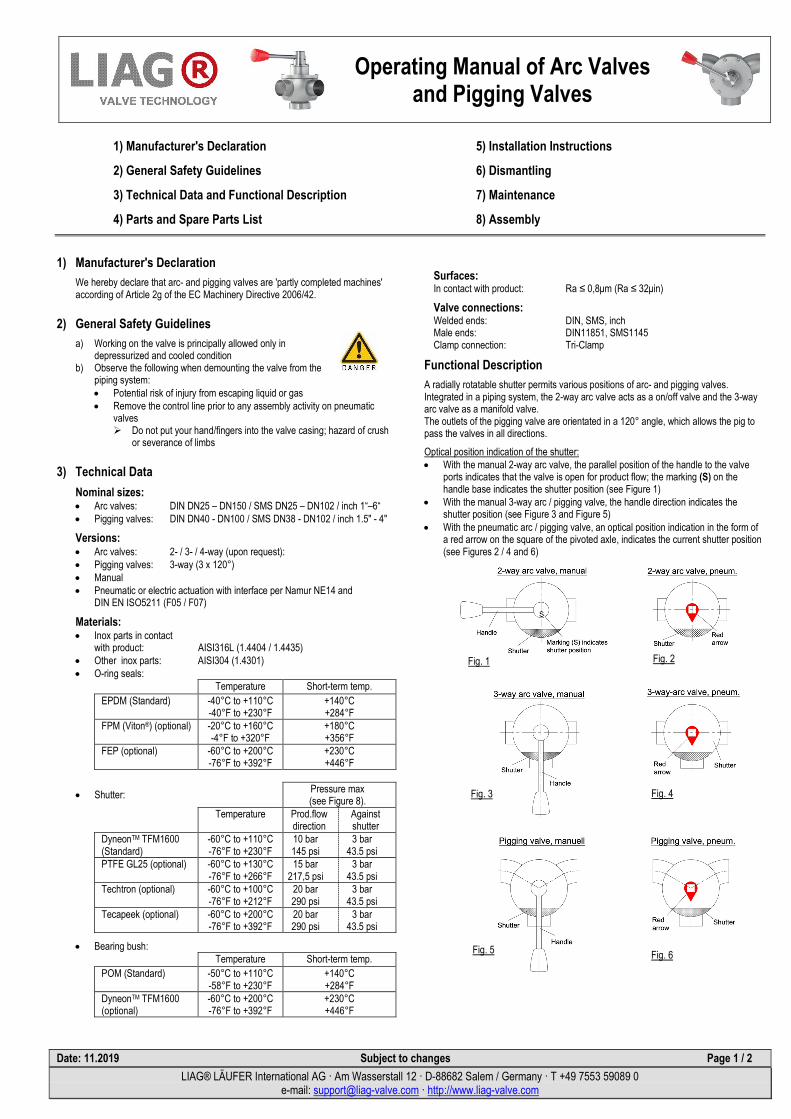
A radially rotatable shutter permits various positions of arc- and pigging valves. Integrated in a piping system, the 2-way arc valve acts as a on/off valve and the 3-way arc valve as a manifold valve. The outlets of the pigging valve are orientated in a 120° angle, which allows the pig to pass the valves in all directions.
Optical position indication of the shutter: • With the manual 2-way arc valve, the parallel position of the handle to the valve
ports indicates that the valve is open for product flow; the marking (S) on the handle base indicates the shutter position (see Figure 1)
• With the manual 3-way arc / pigging valve, the handle direction indicates the shutter position (see Figure 3 and Figure 5)
• With the pneumatic arc / pigging valve, an optical position indication in the form of a red arrow on the square of the pivoted axle, indicates the current shutter position (see Figures 2 / 4 and 6)
Fig. 1
Fig. 4
Fig. 3
Fig. 6 Fig. 5
Fig. 2
• Shutter:

Operating Manual of Arc Valves and Pigging Valves
Date: 11.2019 Subject to changes Page 2 / 2
LIAG® LÄUFER International AG · Am Wasserstall 12 · D-88682 Salem / Germany · T +49 7553 59089 0 e-mail: [email protected] · http://www.liag-valve.com
4) Parts and Spare Parts List
Parts and Spare Parts List (spares in bold and italic type): Item Designation Qty.
1 Handle or pneumatic actuator 1 2 Bearing cap 1 3 Pivoted axle with arc 1 4 O-ring to the pivoted axle 1 5 Valve casing 1 6 Shutter 1 7 Pinch nut 1 8 O-ring to the cone 1 9 Bearing bush 1 10 O-ring to the bearing cap 1 11 Fixing screw for handle (actuator) 2 12 Fixing screws for bearing cap 4 13 Allen screw 1 14 Cone 1 15 Snap ring 1
5) Installation Instructions
• The arc / pigging valve is suitable for any installation position • For self drainage the valve outlet has to point downward • In order to avoid damage, the arc / pigging valve has to be dismantled
before being welded in place in a piping system • Recommended installation (see Figure 8)
6) Dismantling
1. Never demount a pressurized arc / pigging valve. 2. Loosen the fixing screws (11) on the handle to remove the handle (1). 3. Loosen the allen screw (13) on the pinch nut (7) which is connected to the
cone (14) by a snap ring (15). 4. Use a face pin spanner wrench to loosen the pinch nut (7). 5. Loosen the fixing screws (12) to remove the bearing cap (2) incl.
pivoted axle (3) and bearing bush (9). 6. Remove the shutter (6) from the valve casing (5). 7. Pull out the pivoted axle (3) from the bearing cap (2). 8. Take out all O-rings.
7) Maintenance 1. Check functional surfaces in the valve casing (5) for their condition
and clean them accurate. 2. Replace all O-rings: O-ring to the pivoted axle (4), O-ring to the cone (8),
O-ring to the bearing cap (10). 3. Prior to assembly, lubricate O-rings with food-safe grease "Klüber Paraliq
GTE 703“. 4. Check proper working order of the bearing bush (9) and replace as necessary. 5. Clean shutter (6) and check for proper working and wear; replace as necessary.
Lubricants • For arc / pigging valve O-ring seals in contact with product (EPDM / FPM / FEP): Klüber Paraliq GTE 703 NFS H1
• For inox screws DIN912 and DIN933: Klüber lubricating paste UH1 84-201
Recommendation for cleaning (CIP) Optimal cleaning results will be accomplished with switching of the arc / pigging valve while flushing (CIP).
8) Assembly 1. Check all components for cleanliness and proper condition prior to arc / pigging
valve assembly. 2. Insert bearing bush (9) into bearing cap (2). 3. Insert O-rings (4), (8) and (10). 4. Assemble pivoted axle with arc (3) and bearing cap (2). Pay attention to the
marking (0) on the square pin of the pivoted axle (3) indicates the shutter position (6) (see Figure 9).
5. Insert shutter (6) into valve casing (5). 6. Fit the pivoted axle with the arc (3) together with bearing cap (2) to the valve
casing (5) as follows: a) The pivoted axle with arc (3) is designed that it exerts a defined pressure
on the shutter (6) during assembly. On account of the preload characteristics, the bearing cap (2) declines approx. 4-5mm off the valve casing (5) on the opposite side of the shutter (see Figure 9).
b) The shutter should be positioned to the inner casing wall to prevent damages on the plastic surface.
c) Fasten the handle (1) in the desired position. Note: For arc / pigging valves with pneumatic actuator proceed as follows: before assembly of the actuator, turn the square pin of the pivoted axle (3) into the desired shutter position by means of a jaw spanner and the marking (0).
7. Put in place and tighten the bearing cap fixing screws (12).
8. Assemble the pinch nut (7) to the valve casing (5) by using a face pin spanner and a torque wrench: Torque 4Nm Alternative: Screw pinch nut (7) by hand as far as possible (without using a tool) to the valve casing (5). Switch valve several times (approx. 5 x) and then slightly retighten pinch nut with cone (7) by hand and/or with face spanner (approx. 90°).
9. Secure pinch nut (7) with allen screw (13).
Fig. 8
Fig. 7
Fig. 9