Operating Instructions - TU...
29
Operating Instructions Pirani Vacuum Gauges & Dual Set Point Controllers 0.01 to 100 mTorr (10 -5 to 0.1 Torr) 1 to 2000 mTorr .01 to 20 Torr .01 to 100 x 10 -3 mbar .001 to 2.000 mbar .01 to 20.00 mbar .001 to 13.333 Pascals 0.1 to 200.0 Pascals 1 to 2000 Pascals
Transcript of Operating Instructions - TU...

Operating InstructionsPirani Vacuum Gauges & Dual Set Point Controllers
0.01 to 100 mTorr (10-5 to 0.1 Torr)
1 to 2000 mTorr
.01 to 20 Torr
.01 to 100 x 10-3 mbar
.001 to 2.000 mbar
.01 to 20.00 mbar
.001 to 13.333 Pascals
0.1 to 200.0 Pascals
1 to 2000 Pascals

ContentsINTRODUCTION . . . . . . . . . . . . . . . . . . . . . . . . . . . . . . . . 1
Instruments Covered By This Manual . . . . . . . . . . . . . . . . . . . . . . . 2Vacuum Gauge Indicator . . . . . . . . . . . . . . . . . . . . . . . . . . . . . . . . . 3Portable Vacuum Gauge Indicator . . . . . . . . . . . . . . . . . . . . . . . . . . 3Dual Set Point Controller . . . . . . . . . . . . . . . . . . . . . . . . . . . . . . . . . 4
SPECIFICATIONS . . . . . . . . . . . . . . . . . . . . . . . . . . . . . . 5
INSTALLA TION . . . . . . . . . . . . . . . . . . . . . . . . . . . . . . . . 7
Unpacking Instructions . . . . . . . . . . . . . . . . . . . . . . . . . . . . . . . . . . 7Panel Mounting . . . . . . . . . . . . . . . . . . . . . . . . . . . . . . . . . . . . . . . 8 Gauge Tube Installation. . . . . . . . . . . . . . . . . . . . . . . . . . . . . . . . . 10
OPERATING INSTRUCTIONS. . . . . . . . . . . . . . . . . . . . . 11
Readings On The Display. . . . . . . . . . . . . . . . . . . . . . . . . . . . . . . . 11Setting the Control Points . . . . . . . . . . . . . . . . . . . . . . . . . . . . . . . 12Relay Output Connector Wiring. . . . . . . . . . . . . . . . . . . . . . . . . . . 12Analog Output Signal . . . . . . . . . . . . . . . . . . . . . . . . . . . . . . . . . . .13
Optional 4-20 mA and 0-5 or 0-10 VDC Output. . . . . . . . . . . . . .14Calibration . . . . . . . . . . . . . . . . . . . . . . . . . . . . . . . . . . . . . . . . . . 15
Zero & Span Adjustment Using Reference Calibrator . . . . . . . . .15Setting Zero And Span Using Manometer . . . . . . . . . . . . . . . . . 16
Cable Extensions. . . . . . . . . . . . . . . . . . . . . . . . . . . . . . . . . . . . . .17Three Position Gauge Tube Selector Switch Operation . . . . . . . . . 18
TECHNICAL DATA . . . . . . . . . . . . . . . . . . . . . . . . . . . . .19
Troubleshooting. . . . . . . . . . . . . . . . . . . . . . . . . . . . . . . . . . . . . . .19Gauge Tube Wiring . . . . . . . . . . . . . . . . . . . . . . . . . . . . . . . . . . . 19Changing Operating Line Voltage . . . . . . . . . . . . . . . . . . . . . . . . . 20Set Point Hysteresis . . . . . . . . . . . . . . . . . . . . . . . . . . . . . . . . . . . 20
WARRANTY AND RETURN PROCEDURE . . . . . . . . . . . 22
Warranty Statement . . . . . . . . . . . . . . . . . . . . . . . . . . . . . . . . . . .22Return Shipment Procedure . . . . . . . . . . . . . . . . . . . . . . . . . . . . . .22
PARTS AND ACCESSORIES . . . . . . . . . . . . . . . . . . . . . 23
DIMENSION DRAWINGS . . . . . . . . . . . . . . . . . . . . . . . . 24
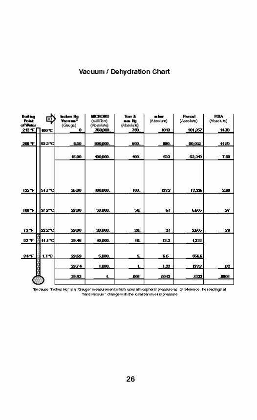
VACUUM / DEHYDRATION CHART . . . . . . . . . . . . . . . . 26
Rev. 9, 4/04

1
1. INTRODUCTIONThe Vacuum Gauge Indicator and Dual Set-point Controllerare compact vacuum measurement and control instru-ments that offer the precision and high resolution of digitalelectronics at the same price as analog controls. Theseinstruments introduce a newly developed sensor whichincorporates an up-scale trim to improve trackingability. The extremely rugged sensor is constructed witha solid, inert, noble metal that maintains its characteristicsover long periods.
Cooler operating temperatures, half that of thermopilegauges, enhances stability as does a unique temperaturecompensation network. Replacement gauge tubes areinterchangeable and have time constants of less than 0.3seconds for the 2000 mT and 20 Torr instruments. (The100 mT instrument is slower.)
Both the indicator and controller instruments feature simple, single hole installation. A new panel mountingsystem permits easy installation of the gauges into panelcutouts originally designed for Hastings, Varian, Televacand other analog meters without modifications. The standard 20 Torr and 2000 mT gauge tubes have 1/8 inchNPT male thread or fit into quick connects sized for 1/8inch pipe (0.405 inch dia.) The standard 100 mTorr tubehas 3/4" O.D. smooth tubulation.
While the instruments are not completely immune to shockand vibration, they do not have a delicate analog meterand therefore are considerably more rugged than analogtypes and much more resistant to pump vibration.

2
This manual covers the following instruments:
• 0.01 to 20 Torr indicator• 0.01 to 20 Torr indicator and controller
• 1 to 2000 mT indicator• 1 to 2000 mT indicator and controller
• 1 to 2000 mT portable, battery powered indicator
• 0.01 to 100 mT indicator• 0.01 to 100 mT indicator and controller
Each of the instruments is designed for a specific pressure range. With the exception of the range, all indicators operate in the same manner, and all controllersoperate in the same manner.
The instruments must be paired with a gauge tube of thesame range for proper operation. Replacement gaugetubes are matched so they are interchangeable (in the same range) without recalibration. Stainless steel gaugetubes are available for use with the .01 to 20 Torr and the1 to 2000 mT instruments.
1.1. Instruments Covered By This Manual
1.2. Vacuum Gauge Indicator
1.3. Portable Vacuum Gauge Indicator
The indicator instruments are rugged, digital vacuumgauges. They are small, compact instruments that powera Pirani-type gauge tube which senses changes in pressure by measuring the thermal conductivity of the residual gases in the vacuum system. The sensors aremade of an inert, noble metal that does not oxidize orcorrode. The long-term life expectancy for the gauge tube is excellent if kept clean and free of oil or other evaporated contaminates from the vacuum system.
Your instrument is ready to operate as received. Simplyinstall the gauge tube, connect the gauge tube cable,and plug the line cord into an AC power outlet to placethe indicator in operation.
The instrument is powered from a 115 VAC or 230 VACline as specified when ordering. Power consumption isabout 1 Watt. Either 50 or 60 Hz power may be used.
A 10 foot long gauge tube cable is attached and exten-sions up to 500 feet (if using #18 wire) may be addedwithout affecting calibration. See section on CableExtensions for more information.
The battery powered gauge is ready to operate asreceived. The gauge displays a vacuum pressure readingfor approximately one minute each time the “ON” switchis pressed. An automatic shut-off circuit turns the displayoff in order to conserve battery life. The Tube TypeSelector Switch can be set for Pirani tubes, such as theKJL or VRC D-2000; or alternatives for T/C tubes, suchas the KJL-6000 or Hastings DV6R. The battery gaugereads vacuum in the range of 1 to 2000 mTorr with thePirani tubes, or 1 to 200 mTorr with the T/C tubes. Pressand hold in the “ON” button to check the charge level ofthe battery. Recharge the battery anytime the reading onthe display drops below 960. The gauge can be chargedcontinuously when not in use.
3

1.4. Dual Set Point Controller
The Dual Set Point Controller instruments are combina-tion controller and indicator digital vacuum gauges. Thecontrollers power a Pirani-type gauge tube which senseschanges in pressure by measuring the thermal conduc-tivity of the residual gases in the vacuum system. The sensors are made of an inert, noble metal that does notoxidize or corrode. The long-term life expectancy for the gauge tube is excellent if kept clean and free of oil orother evaporated contaminates from the vacuum system.
In addition to acting as a digital indicator, the Dual SetPoint Controller instrument operates two control relays.Set point pressures are set from the front panel and displayed on the meter. Push-to-set switches simplifydisplay of the set points. Relays have 3 amp contacts,form C, and are terminated in screw terminal connectorson the rear. The mating half of the relay connector isprovided.
The instrument is powered from a 115 VAC or 230 VACline as specified when ordering. Power consumption isabout 2 Watts. Either 50 or 60 Hz power may be used.
A 10 foot long gauge tube cable is attached and exten-sions up to 500 feet (if using #18 wire) may be addedwithout affecting calibration. See section titled, “CableExtensions” for more information.
Installation of the controller is identical to the DigitalIndicator except for wiring the relay connectors for thecontrol action. This is described in the section titled,“Relay Output Connector Wiring.”
4
2. SPECIFICATIONS
5
• Pressure Range: 0.01 to 100.00 mTorr, 1 to 2000mTorr, 0.01 to 20.00 Torr, depending on designedrange of instrument.
• Calibration: Air or Nitrogen.
• Accuracy: Better than 5% of value or:(for 100 mTorr gauges) ±0.03 mTorr,(for 2000 mTorr gauges) ±3 mTorr,(for 20 Torr gauges) ±0.03 Torr,
whichever is larger.
• Set Point Range: Full scale, equal to full scale rangeof instrument.
• Set Point Repeatability: 2 digits.
• Analog Output: 0 to 2.000 volts = 0-2000 mTorr into2000 ohm load or higher; or 2.000 volts = 20.00 Torr;or 1.0000 volt = 100 mTorr. 2 pin connector included.
• Gauge Tube: Gauge tubes for 2000 mT and 20Thave 1/8 inch NPT male thread or fit into quick connects sized for 1/8 inch pipe (0.405 inch dia.)100 mTorr tube has 3/4 inch O.D. smooth tubulation.
• Power Consumption: Approx. 1 Watt for indicator,2 Watts for Controller @ 115 VAC (4 Watts for 20 Torrmodels).
• Relays: SPDT 3 Amp @115VAC; non-inductive loads.
• Temperature Effects: (For 2000 mT): changes in ambient temperature between 0°C and 50°Cchange the reading less than 0.2 mT per °C at 50mT; less than 4 mT per °C at 900 mT. (For 20 Torr):Changes in ambient temperature between 0°C and50 °C change the reading less than 0.01 Torr per °C.(For 0.01 to 100 mT): Changes in ambient temperaturebetween 0° C and 50° C change the reading less than0.004 mTorr per °C at hard vacuum and 0.4 mTorr at50 mTorr.
• Line Power: 115VAC, 50/60 Hz; 230 VAC optional atno additional cost.
6
• Line Regulation: ±20% produces less than 1% change in reading.
• Dimensions: See drawing at back.
• Mounting: Panel mounting hardware is includedwith each gauge and controller.
• Gauge Tube Cables: 10 foot (305 cm) attached; 4wire for 2000 mT and 100 mT, 6 wire for 20 Torr.
• Extension Cables: Change gauge tube cable lengthwithout recalibration. Extensions to 500 feet (150M)can be provided.
• Relay Output: 3 pin screw terminal connectors.
• Line Cord: 5 1/2 feet (170 cm) long.
• Net Weight: Indicator: 1 lb. 2 oz. (0.5 kgs);Controller: 1 lb. 6 oz. (0.6 kgs).
• Shipping Weight: Indicator: 2 lbs., 8 oz. (1.1 kg);Controller: 3 lbs. (1.3 kg).
3. INSTALLATION
7
The instruments and gauge tubes are carefully packagedto protect them during shipment. Use reasonable carewhen removing them from the shipping box.
Inspect the instruments and gauge tubes carefully whenyou receive them. Should either the instruments or thegauge tubes show any signs of damage, file a claim withthe carrier immediately. Do not destroy the shipping con-tainer. It will be required by the carrier as evidence tosupport claims. Call the factory immediately for instruc-tions on return and repair of the instruments.
Please fill out and return the Warranty Registration cardso that we can register your instrument in our warrantyrecords.
3.1. Unpacking Instructions

8
Standard Mounting With Clip
3.78"(96 mm)
4.79" (122 mm)
3.5"(89 mm)
1/4 DIN Enclosure
3.2 Panel Mounting
9
Both the digital indicators and dual set-point controllersmount in a single panel cut out.
Instruments provided in “standard enclolures” fit the same 2.75" (70 mm) round hole as used by Hastings,Televac, Lesker, Varian and other analog meter instru-ments. A ‘U’ shaped panel mounting clip is included withthe instrument. Instruments provided in 1/4 DINEnclosures fit a 92 mm x 92 mm cut out. Jack screwsare included with 1/4 DIN instruments.
1. Loosen the screws and remove the ‘U’ shaped bracketfrom the standard enclosure or the 2 jack screws fromthe sides of the 1/4 DIN enclosure. Feed the power andgauge tube cables through the panel cutout and hold theinstrument flush against the panel.
2. Reinstall the ‘U’ clip or jack screws. Lightly tighten(finger tight) the jack screws against back of the panel.
3. Adjust the front panel of the instrument to be squareand level and tighten jackscrews snugly. Do not over-tighten.
4. Connect the power cord to an AC line power outlet ofthe appropriate voltage. Power consumption is approximately 2 watts.
5. Unless tagged, the instrument is shipped ready foroperation on 115 VAC. If modified at the factory for230/240 volt use, the 115 volt connector will be removedand the instrument tagged or marked for 230 volt opera-tion. The customer will then be required to wire thepower cord to his connector as follows:
Black = Line White = Neutral Green = Ground
6. After the gauge tube is installed in the vacuum sys-tem, connect the gauge tube cable to the gauge tube(See the following section, “Gauge Tube Installation”, formore information on installing the gauge tube).
7. For controllers, please refer to the section titled, “RelayOutput Connector Wiring” for information on connectingthe output relays. Information on connecting the analogoutput signal for both the indicator and the controllerinstruments is contained in the section titled, “AnalogOutput Signal”.
10
3.3. Gauge Tube Installation
1. Thread the gauge tube into a 1/8 inch NPT female fit-ting (or other fitting or flange as per your gauge tube), inthe vacuum system. The preferred mounting is with the open end pointing down so as to be self draining to anycondensation. However, mounting in any position is ac-ceptable.
2. An appropriate thread sealant is required to insurethat the threaded connection will not leak. Teflon threadtape may be used to seal the threads if care is used so itwill not shred off and get inside the tube or vacuum sys-tem. It is better to use mini-seal or an epoxy sealer onthe threads.
3. An excellent mounting system is to use an O-ringquick connect to install the gauge tube. These may be permanently installed in the system by welding, brazingor soldering. For the 100 mTorr gauge tube a 3/4" quickconnect is required. The quick connects are availablefrom vacuum equipment suppliers such as the KurtLesker Co. (1-800-245-1656).
4. Another alternative is to use quick flange adaptors.Gauge tubes can be ordered with QF, VCR, and Mini-Conflat flanges.
4. OPERATING INSTRUCTIONS
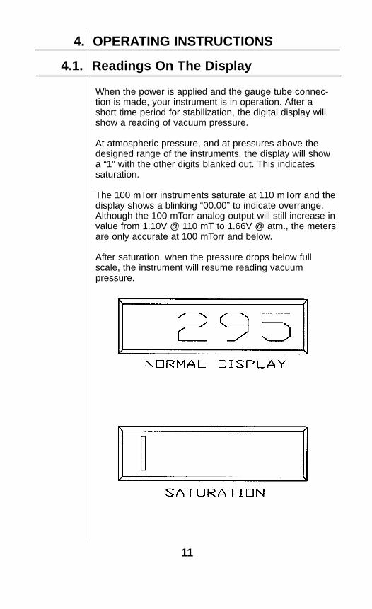
When the power is applied and the gauge tube connec-tion is made, your instrument is in operation. After ashort time period for stabilization, the digital display willshow a reading of vacuum pressure.
At atmospheric pressure, and at pressures above the designed range of the instruments, the display will showa “1” with the other digits blanked out. This indicatessaturation.
The 100 mTorr instruments saturate at 110 mTorr and thedisplay shows a blinking “00.00” to indicate overrange.Although the 100 mTorr analog output will still increase invalue from 1.10V @ 110 mT to 1.66V @ atm., the metersare only accurate at 100 mTorr and below.
After saturation, when the pressure drops below fullscale, the instrument will resume reading vacuum pressure.
4.1. Readings On The Display
11

4.2. Setting the Control Points
4.3. Relay Output Connector Wiring
Contact Rating: —3 amps, 120 VAC, resistive—1.5 amp, 230 VAC, resistive—1.5 amp, 28 VDC, inductive
Gently pull the connectors and they will detach fromtheir sockets for wiring. Plug back in when connectionsare made. The “Low” set point relay is on the right sidewhen looking at the instrument from the rear.
12
To set the control points, press in either the Low or High“Push To Display” push-button on the front panel. This willdisplay that set point on the digital meter. Adjust themulti-turn pot that corresponds to that set point until thedesired pressure for the control action is read on themeter. The set point adjustment pots are located on thefront panel on either side of the LEDs. Release the “PushTo Display” push-button and the instrument will againread pressure.
If the meter saturates and reads 1 xxx with the right-mostdigits (xxx) blanked out, the control pressure setting is stillcorrectly displayed when either of the push-buttons aredepressed.
The LED’s show control action in the following manner: —Relay energized, LED is ON ; de-energized, LED is
OFF—Relays are de-energized when pressure is above the
set-point (on atmospheric pressure side of set point.)—Atmospheric pressure = de-energized = loss of power—“NORMAL” = de-energized relay
Relay Connectors On Rear Of Controller
“High Relay “Low Relay
4.4. Analog Output Signal
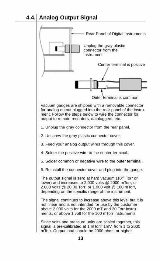
Vacuum gauges are shipped with a removable connectorfor analog output plugged into the rear panel of the instru-ment. Follow the steps below to wire the connector foroutput to remote recorders, dataloggers, etc.
1. Unplug the gray connector from the rear panel.
2. Unscrew the gray plastic connector cover.
3. Feed your analog output wires through this cover.
4. Solder the positive wire to the center terminal.
5. Solder common or negative wire to the outer terminal.
6. Reinstall the connector cover and plug into the gauge.
The output signal is zero at hard vacuum (10-4 Torr orlower) and increases to 2.000 volts @ 2000 mTorr; or2.000 volts @ 20.00 Torr; or 1.000 volt @ 100 mTorr,depending on the specific range of the instrument.
The signal continues to increase above this level but it isnot linear and is not intended for use by the customerabove 2.000 volts for the 2000 mT and 20 Torr instru-ments, or above 1 volt for the 100 mTorr instruments.
Since volts and pressure units are scaled together, thissignal is pre-calibrated at 1 mTorr=1mV, from 1 to 2000mTorr. Output load should be 2000 ohms or higher.
Rear Panel of Digital Instruments
Unplug the gray plasticconnector from the instrument
Center terminal is positive
Outer terminal is common
13

4.4.1 Optional 4-20 mA and 0-5 or 0-10 VDC Output
Gauges provided with an optional output are built in 1/4DIN size cabinets which mount in 92 mm square panelcut-outs.
On the rear panel of the instrument you will find a sectionidentified as “analog output” which includes the zero and span adjustment potentiometers and a male connec-tor for the 4-20 mA, 0-5 or 0-10 VDC outputs.
Unplug this connector and unscrew the gray plasticshroud. Feed a shielded wire through this shroud andsolder the shield to the outside lug and the center con-ductor to the inner lug. The shield is the circuit commonor zero and the center conductor is 20 mA, 5 or 10 volts.The output is floating. The resistance in the mA outputloop can be up to 1000 ohms. The 5 or 10 VDC outputshould have loads of 2000 ohms or higher.
Before being shipped from the factory the 4 mA is scaled to the low end of the instrument range (or zero pressure)and the 20 mA is adjusted to coincide with the full scaleinstrument reading of 100mT, 2000mT, 20.00 Torr or1500 Torr. Instruments built with 5 or 10 VDC outputsare also scaled before shipping. Rear panel zero andspan adjustments are provided with all output rangesshould fine tuning in the field be required.
The standard analog output voltage signal described insection 4.4 of the manual continues to function evenwhen these optional outputs are provided.
4.5. Calibration
There are only 3 calibration adjustments that are normallynecessary to re-standardize the instrument. One is anoffset adjustment. The other two amount to a “zero”adjustment for hard vacuum, and a span adjustment toset up scale tracking at some known pressure. There aretwo methods for setting these adjustments. The methodsare described in the following two sections.
14
15
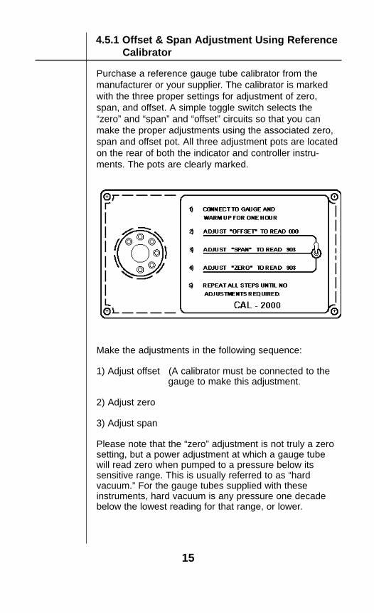
4.5.1 Offset & Span Adjustment Using ReferenceCalibrator
Purchase a reference gauge tube calibrator from themanufacturer or your supplier. The calibrator is markedwith the three proper settings for adjustment of zero,span, and offset. A simple toggle switch selects the“zero” and “span” and “offset” circuits so that you canmake the proper adjustments using the associated zero,span and offset pot. All three adjustment pots are locatedon the rear of both the indicator and controller instru-ments. The pots are clearly marked.
Make the adjustments in the following sequence:
1) Adjust offset (A calibrator must be connected to thegauge to make this adjustment.
2) Adjust zero
3) Adjust span
Please note that the “zero” adjustment is not truly a zerosetting, but a power adjustment at which a gauge tubewill read zero when pumped to a pressure below itssensitive range. This is usually referred to as “hardvacuum.” For the gauge tubes supplied with these instruments, hard vacuum is any pressure one decadebelow the lowest reading for that range, or lower.
4.5.2. Setting Zero And Span Using Manometer
16
This method requires a high vacuum system and aprecision calibration “standard” such as a capacitancemanometer. If these are not available, use the referencetube technique described previously. The procedurebelow lists ranges and settings for a 2000 mTorr instru-ment as an example.
To set zero and span using a capacitance manometerfor the 2000 millitorr instrument requires a high vacuumsystem capable of pressures less than 1 x 10⁻⁴ Torr,and a precision calibration “standard” such as a capacitance manometer with a 1 Torr or 10 Torr head.
First, pump the tube to hard vacuum and hold it there forabout 20-30 minutes to thoroughly outgass the tube.Adjust the zero adjustment until it reads 000 on the meter.
Second, raise the pressure to 900 mTorr (for instrumentsof other ranges choose a pressure near mid-scale), andhold that pressure constant. Adjust the span adjustmentpot to read the same pressure as the calibration stand-ard. The instrument is now calibrated. If the span adjust-ment was far off, repeat the procedure.
The span adjustment permits you to trim the instrumentfor precise indication at a critical pressure, increasingthe absolute accuracy at that point, although possiblysacrificing tracking at other points on the scale. The 900mTorr point is best on a 2000 mT instrument for all-around average tracking throughout the 1 to 2000 mTorrrange.
NOTE: If a reference tube or precision calibrationstandard are not available, but you feel there is aneed to calibrate the instrument, then pump to hardvacuum and set the zero only. Do not attempt tomake the reading agree with other typical analogthermocouple or Pirani gauges upscale as this willresult only in degraded performance of this gauge.
››

17
4.6. Cable Extensions
The indicator and controller models are unique in theirability to change cable lengths without requiring recalibration. Typically, for a 2000 mTorr instrument, a 500 foot cable of #18 wire may be added with less than 1 mTorr error.
If factory cables are purchased with the instrument, it willbe calibrated with that cable. Customers making their owncables may do so to any length, provided the wire resist-ance is kept at 3.2 ohms or less per lead, e.g. 500 feet of#18 wire is 3.19 ohms. We suggest using 8-wire #22 forup to 200 foot lengths. Beyond this, we recommend goingto larger size wire. Wire all pins since all are used for thevarious tube types (except pin 2). Be sure to make goodsolder joints. Crimped connections are not recommended.
For long cable extensions, shielded wire may be desirable and is a good precaution against stray electricalnoise. Connect the shield to pin 1, which is circuit common. Extension cables may be purchased from themanufacturer in several standard lengths. If you wish to make your cable extensions, see the pin out details belowfor your specific instrument range.
• 100 mTor: 4 wires, pins 1, 5, 6, 8
• 2000 mTorr: 4 wires, pins 1, 4, 5, 8
• 20 Torr: 6 wires, pins 1, 3, 5, 6, 7, 8
Gauge Tube Wiring Reference Table(Wire Color of Conductors in Extension Cable Shown in Parenthesis)
Pin # 2000 mT 20T 100 mTFunction Color Function Color Function Color
1 GND (BLACK) GND (BLACK) GND (BLACK)
2 — — —
3 — PWR (RED) —
4 PWR (RED) — —
5 SIG (GREEN) SIG (GREEN) SIG (GREEN)
6 — GAIN RES + (BLUE) PWR (RED)
7 — GAIN RES GND (BROWN) —
8 REF (WHITE) REF (WHITE) REF (WHITE)
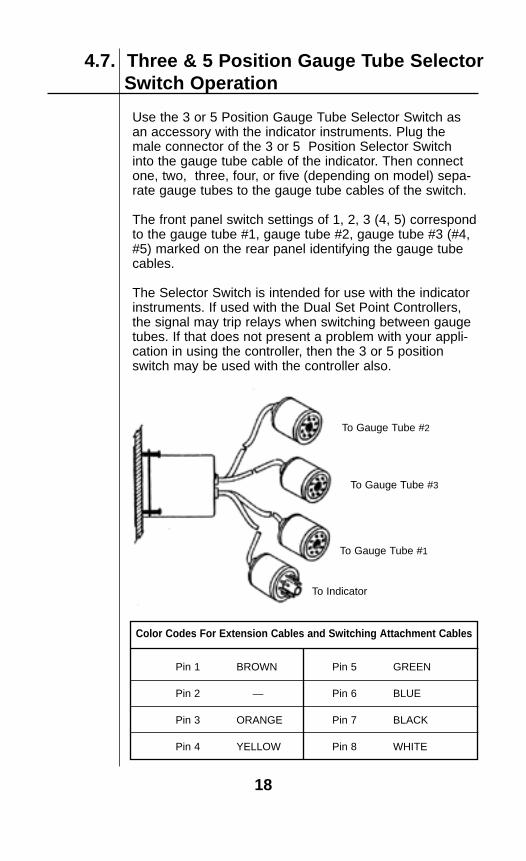
4.7. Three & 5 Position Gauge Tube SelectorSwitch Operation
Use the 3 or 5 Position Gauge Tube Selector Switch asan accessory with the indicator instruments. Plug themale connector of the 3 or 5 Position Selector Switchinto the gauge tube cable of the indicator. Then connectone, two, three, four, or five (depending on model) sepa-rate gauge tubes to the gauge tube cables of the switch.
The front panel switch settings of 1, 2, 3 (4, 5) correspondto the gauge tube #1, gauge tube #2, gauge tube #3 (#4,#5) marked on the rear panel identifying the gauge tubecables.
The Selector Switch is intended for use with the indicatorinstruments. If used with the Dual Set Point Controllers,the signal may trip relays when switching between gaugetubes. If that does not present a problem with your appli-cation in using the controller, then the 3 or 5 positionswitch may be used with the controller also.
18
Color Codes For Extension Cables and Switching Attachment Cables
Pin 1 BROWN Pin 5 GREEN
Pin 2 — Pin 6 BLUE
Pin 3 ORANGE Pin 7 BLACK
Pin 4 YELLOW Pin 8 WHITE
To Gauge Tube #2
To Gauge Tube #3
To Gauge Tube #1
To Indicator

5. TECHNICAL DATA
5.2. Gauge Tube Wiring
It is strongly recommended that every customer keep asmall stock of spare gauge tubes on hand along with aReference Gauge Tube Calibrator.
Always try a new tube before considering circuit failures.The Reference Gauge Tube Calibrator may be connectedto the circuit to prove whether the problem is a gaugetube or circuit failure. If the instrument works properly withthe Reference Gauge Tube Calibrator circuit, then gaugetube failure is a certainty.
19
5.1. Troubleshooting
The gauge tube can be checked with an ohmmeterbetween pins 1 and 5 to verify that the sensor is good.Generally, the reading is less than 2.5 ohms if good; 900ohms if the sensor is broken.
The actual readings for each type of tube should be asfollows:
SENSOR PINS 1 TO 5 HEATERBLACK AND GREEN WIRE WHITE ANDAPPROXIMATE RESISTANCE RED WIRES
100 mT 2.4 Ohms Pin 6 To 8
2000 mT 2.1 Ohms Pin 4 To 8
20 Torr 1.3 Ohms Pin 3 To 8
5.3. Changing Operating Line Voltage
5.4. Set Point Hysteresis
20
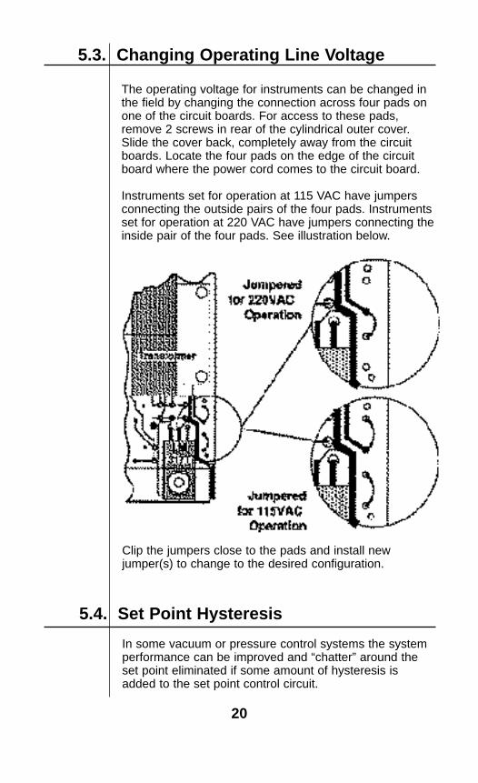
The operating voltage for instruments can be changed inthe field by changing the connection across four pads onone of the circuit boards. For access to these pads,remove 2 screws in rear of the cylindrical outer cover.Slide the cover back, completely away from the circuitboards. Locate the four pads on the edge of the circuitboard where the power cord comes to the circuit board.
Instruments set for operation at 115 VAC have jumpersconnecting the outside pairs of the four pads. Instrumentsset for operation at 220 VAC have jumpers connecting theinside pair of the four pads. See illustration below.
In some vacuum or pressure control systems the systemperformance can be improved and “chatter” around theset point eliminated if some amount of hysteresis isadded to the set point control circuit.
Clip the jumpers close to the pads and install newjumper(s) to change to the desired configuration.

21
Our standard gauges are shipped without a resistor in theR-5 position in the high relay circuit and without a resistorin the R-13 position in the low relay circuit. This producesabout ± 1 digit hysteresis.
Installing resistor values as shown in the table willincrease the hysteresis. Keep in mind that these are digits, not mTorr, Torr, or any other pressure unit. ±10 digits is ±10 mTorr on a 2000 mTorr full scale instrument.On an instrument with full scale of 20.00 Torr ± 10 digitsis +/-.10 Torr. The set point is always in the middle of thehysteresis band. For example, a 20.00 Torr gauge with aset point of 15.00 Torr and a hysteresis of ± 10 digitswould cause the relay to change state at 15.10 Torr and14.90 Torr.
2 megohm ± 2 digits
1 megohm ± 3 digits
700 K ohm ± 5 digits
500 K ohm ± 7 digits
365 K ohm ± 10 digits
250 K ohm ± 15 digits
200 K ohm ± 20 digits
160 K ohm ± 50 digits
80 K ohm ± 100 digits
ResistanceValue
HysteresisBand Width
R-5 and/or R-13 Resistors

6. WARRANTY AND RETURN PROCEDURE
6.2. Return Shipment ProcedureIf repairs are required, return the instrument with cablesand gauge tube to the manufacturer, pre-paid. Include apurchase order and statement of the nature of the problem.
22
The manufacturer warrants all instruments for a period of twoyears against defects of material and workmanship subject tothe terms and conditions set forth below:
1. The warranty is in effect at date of shipment from the manu-tacturer to the original purchaser.
2. Expendables such as gauge tubes, etc. are not covered bythis warranty.
3. Claims against this warranty for replacement parts and/orservice shall be limited to defects in materials and workmanship.Malfunctions attributable to neglect, abuse, or repair and opera-tional procedures not specifically recommended by the manufac-turer are not warranted.
4. Service repairs and/or piece part replacement shall be war-ranted for a period of ninety (90) days commencing on date ofreturn shipment or until expiration of the remaining term of origi-nal instrument warranty, whichever is later.
5. The manufacturer shall not be liable tor consequential damages nor for labor, loss or expenses directly or indirectlyarising from use of their products or equipment.
6.This warranty does not apply to shipping damage. Claims for damage incurred while products are in transit rest with purchaser. Said claims are to be levied against the carrier.
7. Amendments, assumed corollaries or statements contrary tothe terms of this warranty shall not be binding upon the manufacturer unless stated in writing and approved by an officerof the manufacturer.
8. THE MANUFACTURER MAKES NO OTHER WARRANTY,EXPRESSED OR IMPLIED, AND MAKES NO WARRANTY OFMERCHANTABILITY OR OF FITNESS FOR ANY PAR-TICULAR PURPOSE.
9. Warranty service is F.O.B. point of manutacture. All trans-portation charges to and from the manufacturer’s plant shall bethe responsibility of the purchaser.
6.1. Warrany Statement
7. PARTS AND ACCESSORIESGauges and Controllers0.01 - 100 mTorr Dual Set Point Controller......................................9020050.01 - 100 mTorr Indicator................................................................9020061 - 2000 mTorr Dual Set Point Controller.........................................9020011 - 2000 mTorr Indicator...................................................................9020021 - 2000 mTorr Portable, Battery Powered Indicator........................9020170.01 - 20 Torr Dual Set Point Controller...........................................9020150.01 - 20 Torr Indicator.....................................................................9020161 mTorr- 20 Torr Dual Range Indicator.............................................9020251 - 1500 Torr Dual Set Point Controller (±1 Torr).............................9020191 - 1500 Torr Indicator (±1 Torr).......................................................90202030" Hg - 100 PSIG Dual Set Point Controller...................................90400130" Hg - 100 PSIG Indicator............................................................904002.01 - 20 PSIG Dual Set Point Controller..........................................904005.01 - 20 PSIG Indicator....................................................................904006.01 - 200 PSIG Dual Set Point Controller........................................904003.01 - 200 PSIG Indicator..................................................................904004
Gauge Tubes, Sensors, and Accessories
0.01 to 100mTorr GaugeTube 3/4"OD Tubulation...........................9120180.01 to 100 mTorr Gauge Tube KF Flange .....................................9120370.01 to 100 mTorr Gauge Tube,1.33 in Conflat, non-rotatable........9121600.01 to 100 mTorr Gauge Tube, 2.75 in Conflat, non-rotatable.......9120380.01 to 100 mTorr Gauge Tube, 15 mm Diameter Tube.................9121011 to 2000 mTorr Gauge Tube with 1/8 in. NPT Male Thread...........9120011 to 2000 mTorr Gauge Tube with KF-16 Flange ........................... 9120051 to 2000 mTorr Gauge Tube with 1.33 in Conflat, non-rotatable... 9120671 to 2000 mTorr Gauge Tube with VCR-4 Fitting............................9120681 to 2000 mTorr Gauge Tube,15 mm Diameter Tube......................9121021 to 20 Torr Gauge Tube with 1/8 in. NPT Male Thread..................9120111 to 20Torr Gauge Tube with KF-16 Flange ....................................9120721 to 20 Torr Gauge Tube with 1.33 in Conflat, non-rotatable.......... 9120731 to 20 Torr Gauge Tube with VCR-4 Fitting...................................9120741 to 20 Torr Gauge Tube,15 mm Diameter Tube ............................912103All Stainless Steel Gauge Tubes for outdoor applications or whereverthe use 304 SS is appropriate. All wetted parts as well as an externalparts and connector pins are 304 SS. . . .Add “SS” prefix to any tube P/N.Extension Cable with Connectors for All Tubes (not wide range)....9120633 Position Gauge Tube Selector......................................................902027Gauge Tube Baffle, Brass 1/8 NPT................................................. 9120071 - 2000 mTorr Vacuum Gauge Calibrator.......................................912008.01 - 20 Torr Vacuum Gauge Calibrator........................................... 912009100 mTorr Vacuum Gauge Calibrator..............................................912019Single Bench Mount Cabinet (fits instruments of any span) .........V805002Double Bench Mount Cabinet (accommodates 2 instrumentsor instrument & 3 pos. selector......................................................V8050031/4 Din Bezel Kit (for 92 mm DIN cutout, fits any instrument).......V805004Handle for Bench Mount Cabinet..................................................V805005Lined Carry Case for Portable Gauge.............................................912028
VRC-6M & VRC 6R Gauge Tubes Interchangeable with Teledyne-Hastings DV-6 TubesVRC-6M Gauge Tube, All Metal 1/8 NPT........................................ 912086VRC-6M-KF 16 Gauge Tube, All Metal, KF-16 Flange....................912096VRC-6M-VCR-4 Gauge Tube, All Stainless Steel, VCR-4...............912082VRC-6R Gauge Tube, All Stainless Steel,1/8 NPT..........................912087VRC-6R-KF 16 Gauge Tube, All Stainless Steel, KF-16 Flange.....912098VRC-6R-VCR-4 Gauge Tube, All Stainless Steel, VCR-4...............912099
23

Standard EnclosureThe standard enclosure has a cylindrical body that fits thesame 2.8 inch diameter panel cutout as Hastings, Televac,and other gauges. Panel mounting hardware is includedwith standard enclosure.
3.5"(89 mm)
Ø2.75"(70 mm)
4.84" (123 mm)
0.50" (13 mm)Max. Panel Thickness
8. DIMENSION DRAWINGS
Indicators and Controllers AreAvailable In 2 Enclosure Styles
1/4 DIN EnclosureThe 1/4 DIN enclosure is rectangular and fits the standard92mm x 92mm panel cutout. Panel mounting jackscrewsare included with 1/4 DIN enclosure.
3.78"(96 mm)
3.5"(89 mm)
4.87" (119 mm)
PANEL MOUNTJACK SCREW
24

25
To adjust Zero, Span and Offset use 2000 mT calibrator P/N # 912008To adjust THR use 1000 mT calibrator P/N 902114
1 To 2000 mTorr Portable Battery Gauge
0.01 to 20.00 Torr Portable Battery GaugeTo adjust Zero, Span and Offset use calibrator P/N # 912009
26

Vacuum Research Corporation • 2419 Smallman Street • Pittsburgh, PA 15222 USAPhone: (800) 426-9340 • (412) 261-7630 • FAX: (412) 261-7220
e-mail: [email protected]