Operating Instructions Manual Solenoid Dosing Pump...
54
Two sets of operating instructions are required for the safe and correct use of the metering pumps: The product specific operating instructions manual and the “General Operating Instructions ProMinent ® Solenoid Metering Pumps”. The two are valid only when read in conjunction with one another. Please read the Operating Instructions manual through completely before commissioning this equipment. Do not discard! The operator shall be liable for any damage caused by installation or operating errors! ProMinent Pr o Minent ® Operating Instructions Manual Solenoid Dosing Pump Beta ® BT4a and BT5a Part No. 987871 ProMinent Dosiertechnik GmbH · 69123 Heidelberg · Germany BA BE 021 07/08 GB Please enter identcode of the device here. BT4A ___ ___ ___ ___ ___ ___ ___ ___ ___ ___ ___ ___ ___ ___ BT5A ___ ___ ___ ___ ___ ___ ___ ___ ___ ___ ___ ___ ___ ___
Transcript of Operating Instructions Manual Solenoid Dosing Pump...

Two sets of operating instructions are required for the safe and correct use of the metering pumps:The product specific operating instructions manual
and the “General Operating Instructions ProMinent® Solenoid Metering Pumps”.The two are valid only when read in conjunction with one another.
Please read the Operating Instructions manual through completely before commissioning this equipment.Do not discard! The operator shall be liable for any damage caused by installation or operating errors!
Publishing details:Operating Instructions for Solenoid Dosing Pump ProMinent® Beta®
© ProMinent Dosiertechnik GmbH, 1998
Address:ProMinent Dosiertechnik GmbHIm Schuhmachergewann 5-1169123 [email protected]
Subject to technical modifications
Pro
Min
ent
ProMinent®Please tear out this page!
ProM
inen
t®
Operating Instructions ManualSolenoid Dosing PumpBeta® BT4a and BT5a
Part No. 987871 ProMinent Dosiertechnik GmbH · 69123 Heidelberg · Germany BA BE 021 07/08 GB
Please enter identcode of the device here.
BT4A ___ ___ ___ ___ ___ ___ ___ ___ ___ ___ ___ ___ ___ ___
BT5A ___ ___ ___ ___ ___ ___ ___ ___ ___ ___ ___ ___ ___ ___
BA_BE_021_07_08_GB1.p65 04.08.2008, 8:03 Uhr2
General User Information:
This operating instructions manual contains the product descriptions in the main text.
• main points instructions
and safety information are indicated by pictograms (see chap. 2).
NOTE
Working guidelines.
Major ComponentsIllustrated views of Beta®
Page 2
Fig. 01
Page 1
3.1adbc
3.2adbc
3.3adbf
3.4adb
f
3.5aebd
1
abcdefgh
2ab
1 2 3
gc
gc
c
ProMinent®
Major Components
1 Control unit
1a Stroke length adjustment knob1b Red LED display, fault indicator1c Yellow LED display, warning indicator1d Green LED display, operating status1e Multifunction switch1f Mains connector1g External operating terminal1h Float switch connector
2 Power end
2a Relay insertion point2b Optional relay
3 Liquid end
3.1 Liquid end without bleed valve, with/without valve spring3.2 Liquid end without bleed valve, with/without valve spring3.3 Liquid end with bleed valve, with/without valve spring (PP-version)3.4 Liquid end with bleed valve, with/without valve spring (NP-version)3.5 Self-degassing liquid end
3a Liquid end back plate3b Liquid end3c Suction connection3d Discharge connection3e Bleed valve connection (self degassing liquid ends)3f Bleeding/fine bleeding valve3g Bypass tubing nozzle
BA_BE_021_07_08_GB1.p65 04.08.2008, 8:03 Uhr1

ProMinent® Page 3
Table of Contents
Page
1 Application ............................................................................. 4
2 Safety ..................................................................................... 4
2.1 Identification of the notes on safety .............................. 4
2.2 Safety Guidelines ........................................................... 5
2.3 Sound intensity level ...................................................... 5
2.4 EC Declaration of Conformity ........................................ 6
3 Design and Function ............................................................. 7
4 Technical Data ....................................................................... 8
4.1 Identcode ....................................................................... 8
4.2 Sizes and Weights ......................................................... 9
4.3 Capacity Data ................................................................ 12
4.4 Reproducibility ............................................................... 14
4.5 Viscosity ......................................................................... 14
4.6 Materials Information ..................................................... 14
4.7 Electrical Data ................................................................ 14
4.8 Environmental Conditions .............................................. 15
5 Removal of Packaging .......................................................... 16
6 Electrical Installation ............................................................ 16
7 Operation and Settings ........................................................ 17
7.1 Operating Components and Functions ......................... 17
7.2 Beta® Relay Retrofit Kit .................................................. 20
8 Maintenance .......................................................................... 24
9 Repairs ................................................................................... 24
10 Troubleshooting .................................................................... 29
11 Decommissioning, Dismantling and Disposal ................... 29
Appendix: ...................................................................................... 30
Exploded diagrams of liquid ends .......................................... 30
BA_BE_021_07_08_GB2.p65 17.07.2008, 14:35 Uhr3

ProMinent®Page 4
1 Application
The pumps in the ProMinent® Beta® series are microprocessor controlled solenoid meteringpumps.
Liquid media They offer highly accurate reproducible metering in the dosing of liquid chemicals in pressurisedpipe systems and into open and closed containers.
Compatibility Specified components/accessories in the Beta® pump series are compatible with those in theCONCEPT, gamma-Classic and gamma series as follows:
• Signal cable: gamma/Vario two core, and four core for ”external“ function• Two stage float switch (gamma/Vario)• gamma discharge line• Standard gamma connector set• gamma wall mounting bracket• Feed container and fixing plates• Total height (distance between suction and discharge line connectors)• Distance between the connectors and mounting holes on the pump• Identical accessories used, e.g. back pressure valves, multifunction valves and flushing
apparatus.
Correct use of equipment
• The Beta® may be used only to meter liquids.• The pump is not designed for use with gaseous chemicals or suspended solids.• Take care when using aggressive chemicals that the materials used in the pump are resistant
to those chemicals (see ProMinent® Chemical Resistance List in the product catalogue orunder www.prominent.com).
• All other applications or modifications are prohibited.• The pump may only be used for applications which correspond to the technical data and
specifications described in the operating instructions manual.• The pump is not designed for use in explosion-hazardous locations.• The Beta® should be operated by suitably trained and authorised personnel only.
2 Safety
2.1 Identification of the notes on safety
The following terms are used in the present operating instructions to indicate the various severitylevels of the danger:
WARNING: Characterizes a possibly hazardous situation. Your life is in danger and thereis a danger of serious injury if these notes are disregarded!
CAUTION: Characterizes a possibly hazardous situation. There is a danger of slight orminor injury or damage to property if these notes are disregarded.
The following warning signs are used in the present operating instructions to indicate differenttypes of danger:
Warning of danger area.
Application / Safefy
BA_BE_021_07_08_GB2.p65 17.07.2008, 14:35 Uhr4

ProMinent® Page 5
Safety
2.2 Safety Guidelines
WARNING
• In emergencies the pump should be switched off immediately! Disconnect the powercable from the power supply!
• Do not dispatch pumps which are designed for use with radioactive chemicals!• When using pumps with flammable chemicals, observe the relevant regulations
concerning the transport and storage of flammable fluids (Ex, Vo, Vb F)!• When installing outside Germany, always observe relevant national regulations!• Combining ProMinent® metering pumps with parts not approved and tested by ProMinent
is not permissible. It can cause injury or damage to persons or materials for which wecannot accept liability!
CAUTION
• Pumps must be accessible at all times for both operating and servicing. Access mustnot be obstructed in any way!
• The pumps and peripherals must be serviced and repaired by qualified and authorisedpersons only!
• Always de-pressurise the liquid end prior to working on a pump!• Empty and rinse the liquid end before working on a pump which has been used with
hazardous or unknown chemicals!• Always read chemical safety data!• Always wear protective clothing when handling hazardous or unknown chemicals!
2.3 Sound intensity level
The sound intensity level is < 70 dB (A) at maximum stroke, maximum stroke rate, maximumback pressure (water) in accordance withDIN EN 12639 (Metering Pump Noise Measurement)
BA_BE_021_07_08_GB2.p65 17.07.2008, 14:35 Uhr5
ProMinent®Page 6
Safety
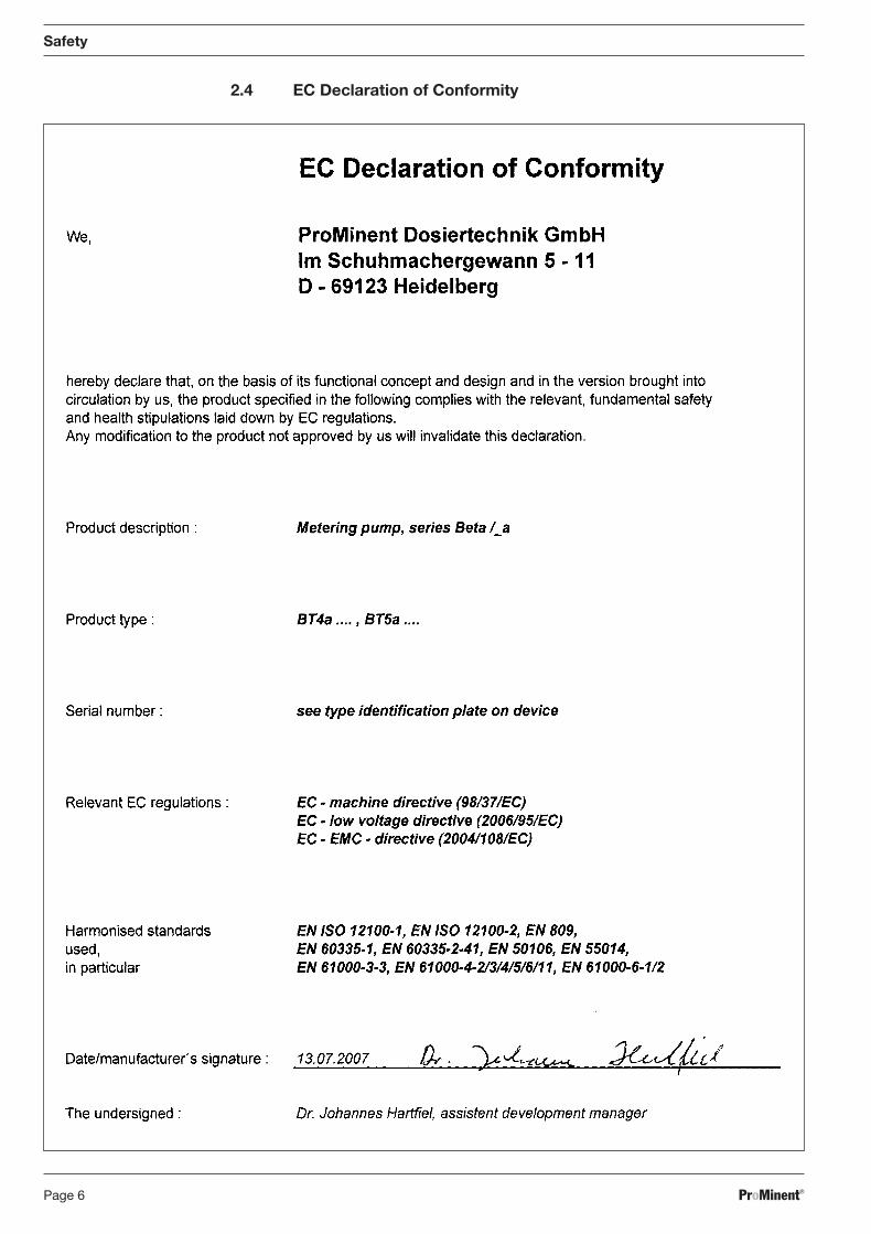
2.4 EC Declaration of Conformity
BA_BE_021_07_08_GB2.p65 17.07.2008, 14:35 Uhr6
ProMinent® Page 7
Design and Function
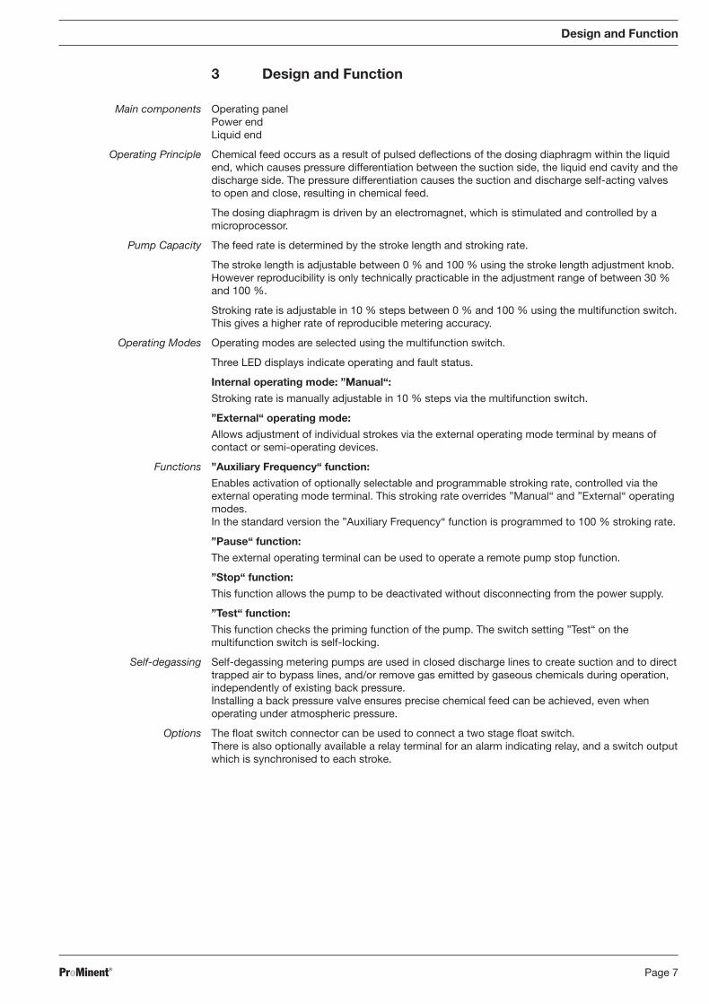
3 Design and Function
Main components Operating panelPower endLiquid end
Operating Principle Chemical feed occurs as a result of pulsed deflections of the dosing diaphragm within the liquidend, which causes pressure differentiation between the suction side, the liquid end cavity and thedischarge side. The pressure differentiation causes the suction and discharge self-acting valvesto open and close, resulting in chemical feed.
The dosing diaphragm is driven by an electromagnet, which is stimulated and controlled by amicroprocessor.
Pump Capacity The feed rate is determined by the stroke length and stroking rate.
The stroke length is adjustable between 0 % and 100 % using the stroke length adjustment knob.However reproducibility is only technically practicable in the adjustment range of between 30 %and 100 %.
Stroking rate is adjustable in 10 % steps between 0 % and 100 % using the multifunction switch.This gives a higher rate of reproducible metering accuracy.
Operating Modes Operating modes are selected using the multifunction switch.
Three LED displays indicate operating and fault status.
Internal operating mode: ”Manual“:
Stroking rate is manually adjustable in 10 % steps via the multifunction switch.
”External“ operating mode:
Allows adjustment of individual strokes via the external operating mode terminal by means ofcontact or semi-operating devices.
Functions ”Auxiliary Frequency“ function:
Enables activation of optionally selectable and programmable stroking rate, controlled via theexternal operating mode terminal. This stroking rate overrides ”Manual“ and ”External“ operatingmodes.In the standard version the ”Auxiliary Frequency“ function is programmed to 100 % stroking rate.
”Pause“ function:
The external operating terminal can be used to operate a remote pump stop function.
”Stop“ function:
This function allows the pump to be deactivated without disconnecting from the power supply.
”Test“ function:
This function checks the priming function of the pump. The switch setting ”Test“ on themultifunction switch is self-locking.
Self-degassing Self-degassing metering pumps are used in closed discharge lines to create suction and to directtrapped air to bypass lines, and/or remove gas emitted by gaseous chemicals during operation,independently of existing back pressure.Installing a back pressure valve ensures precise chemical feed can be achieved, even whenoperating under atmospheric pressure.
Options The float switch connector can be used to connect a two stage float switch.There is also optionally available a relay terminal for an alarm indicating relay, and a switch outputwhich is synchronised to each stroke.
BA_BE_021_07_08_GB2.p65 17.07.2008, 14:35 Uhr7
ProMinent®Page 8
Technical Data
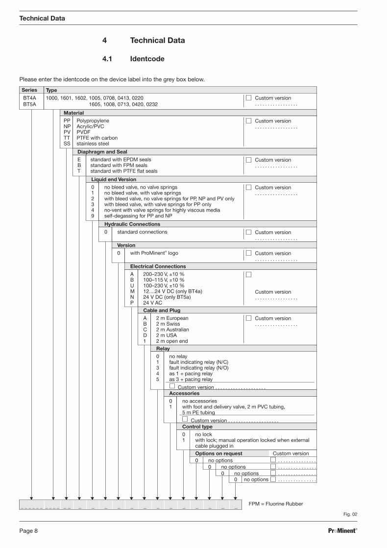
4 Technical Data
4.1 Identcode
Please enter the identcode on the device label into the grey box below.
Fig. 02
FPM = Fluorine Rubber
Series Type
Material
PP PolypropyleneNP Acrylic/PVCPV PVDFTT PTFE with carbonSS stainless steel
BT4A 1000, 1601, 1602, 1005, 0708, 0413, 0220BT5A 0000, 0000, 0000, 1605, 1008, 0713, 0420, 0232
Custom version. . . . . . . . . . . . . . . . .
Custom version. . . . . . . . . . . . . . . . .
0 no options . . . . . . . . . . . . . . .
_ _ _ _ _ _ _ _ _ _ _ _ _ _ _ _ _ __ _ _ _ _ _ _
Diaphragm and Seal
E standard with EPDM sealsB standard with FPM sealsT standard with PTFE flat seals
Liquid end Version
0 no bleed valve, no valve springs1 no bleed valve, with valve springs2 with bleed valve, no valve springs for PP, NP and PV only3 with bleed valve, with valve springs for PP only4 no-vent with valve springs for highly viscous media9 self-degassing for PP and NP
Hydraulic Connections
0 standard connections
Version
0 with ProMinent® logo
Electrical Connections
A 200–230 V, ±10 %B 100–115 V, ±10 %U 100–230 V, ±10 %M 12....24 V DC (only BT4a)N 24 V DC (only BT5a)P 24 V AC
Cable and Plug
A 2 m EuropeanB 2 m SwissC 2 m AustralianD 2 m USA1 2 m open end
Relay
0 no relay1 fault indicating relay (N/C)3 fault indicating relay (N/O)4 as 1 + pacing relay5 as 3 + pacing relay
Custom version . . . . . . . . . . . . . . . . . . . .Accessories
0 no accessories1 with foot and delivery valve, 2 m PVC tubing,
5 m PE tubing
Custom version . . . . . . . . . . . . . . . . . . . .
Custom version. . . . . . . . . . . . . . . . .
Custom version. . . . . . . . . . . . . . . . .
Custom version. . . . . . . . . . . . . . . . .
Custom version. . . . . . . . . . . . . . . . .
Custom version. . . . . . . . . . . . . . . . .
Custom version. . . . . . . . . . . . . . . . .
Control type
0 no lock1 with lock; manual operation locked when external
cable plugged in
Options on request Custom version0 no options . . . . . . . . . . . . . . .
0 no options . . . . . . . . . . . . . . .0 no options . . . . . . . . . . . . . . .
BA_BE_021_07_08_GB2.p65 17.07.2008, 14:35 Uhr8

ProMinent® Page 9
10/15
41/3681/96
K132/144L
(not 0232)12E
95/1
01 148/
160 F
92/102
80/80
M
12 (not 0232)
Beta®/ 4 Beta®/ 5
1000 – 1602 1005 0708 – 0413 0220 1605 1008 – 0713 0420 0232
E 17 7 9 9 13 15 15 5
F 180 187 185 185 193 191 191 197
K 71 71 74 76 71 74 76 76
L 106 105 108 110 105 108 110 91
M Ø 70 Ø 90 Ø 90 Ø 90 Ø 90 Ø 90 Ø 90 Ø 110
Technical Data
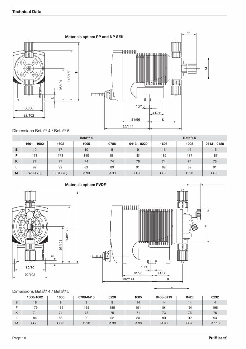
4.2 Sizes and Weights
Materials option: PP
Dimensions Beta®/ 4 / Beta®/ 5
Materials option: NP
81/96132/144
41/36
10/15
KL
M14
80/80
92/102
E
95/1
01 148/
160 F
Dimensions Beta®/ 4 / Beta®/ 5
Beta®/ 4 Beta®/ 5
1000 – 1601 1602 1005 0708 0413 – 0220 1605 1008 0713 – 0420 0232
E 19 17 10 9 9 16 15 15 5
F 171 173 180 181 181 186 187 187 197
K 77 77 74 74 76 74 74 76 76
L 105 105 102 102 104 102 102 104 91
M 62 (Ø 70) 66 (Ø 70) Ø 90 Ø 90 Ø 90 Ø 90 Ø 90 Ø 90 Ø 110
BA_BE_021_07_08_GB2.p65 17.07.2008, 14:35 Uhr9
ProMinent®Page 10
Technical Data
K
M
44
92/102
80/80
E
95/1
01
F
132/144
81/96
10/15
41/36
L
148/
160
Dimensions Beta®/ 4 / Beta®/ 5
Materials option: PP and NP SEK
Beta®/ 4 Beta®/ 5
1601 – 1602 1602 1005 0708 0413 – 0220 1605 1008 0713 – 0420
E 19 17 10 9 9 16 15 15
F 171 173 180 181 181 186 187 187
K 77 77 74 74 76 74 74 76
L 92 92 89 89 91 89 89 91
M 62 (Ø 70) 66 (Ø 70) Ø 90 Ø 90 Ø 90 Ø 90 Ø 90 Ø 90
Materials option: PVDF
92/102
80/80
148/
160
95/1
01
F
E
132/144
81/96
10/15
41/36
M
K
L
1000-1602 1005 0708-0413 0220 1605 0408-0713 0420 0232
E 19 8 8 8 14 14 14 4
F 179 185 185 185 191 191 191 198
K 71 71 73 75 71 73 75 76
L 84 88 90 92 88 90 92 93
M Ø 70 Ø 90 Ø 90 Ø 90 Ø 90 Ø 90 Ø 90 Ø 110
Dimensions Beta®/ 4 / Beta®/ 5
BA_BE_021_07_08_GB2.p65 17.07.2008, 14:35 Uhr10

ProMinent® Page 11
Dimensions Beta®/ 4 / Beta®/ 5
Technical Data
Materials option: TT
K
F
148/
160
95/1
01
E
80/80
92/102
41/36
M
132/144
81/96
10/15
L
M
K
L
10/15
132/144
E
80/80
F
41/36
92/102
95/1
01
81/96
148/
160
Dimensions Beta®/ 4 / Beta®/ 5
Materials option: SS
Beta®/ 4 Beta®/ 5
1000 – 1601 1602 1005 0708 – 0413 0220 1605 1008 – 0713 0420 0232
E 34 27 25 -8 -9 31 -2 -3 -10
F 156 164 165 198 199 171 203 204 212
K 78 72 75 77 77 75 77 77 78
L 89 89 88 91 93 88 91 93 93
M 51 (Ø 60) 66 (Ø 70) 68 (Ø 80) 81 (Ø 85) 81 (Ø 85) 68 (Ø 80) 81 (Ø 85) 81 (Ø 85) 96 (Ø 100)
Beta®/ 4 Beta®/ 5
1000 – 1601 1602 1005 0708 – 0220 1605 1008 – 0420 0232
E 26 19 17 -13 23 -7 -15
F 164 172 173 203 179 209 217
K 78 72 75 77 75 77 78
L 91 91 90 95 90 95 95
M 51 (Ø 60) 66 (Ø 70) 68 (Ø 80) 81 (Ø 85) 68 (Ø 80) 81 (Ø 85) 96 (Ø 100)
BA_BE_021_07_08_GB2.p65 17.07.2008, 14:35 Uhr11
ProMinent®Page 12
Technical Data
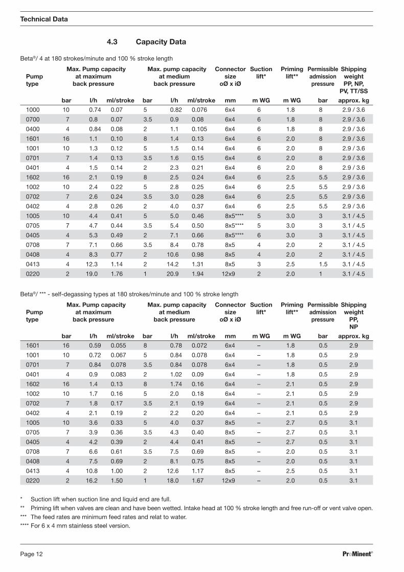
Beta®/ 4 at 180 strokes/minute and 100 % stroke length
4.3 Capacity Data
Beta®/ *** - self-degassing types at 180 strokes/minute and 100 % stroke length
* Suction lift when suction line and liquid end are full.** Priming lift when valves are clean and have been wetted. Intake head at 100 % stroke length and free run-off or vent valve open.*** The feed rates are minimum feed rates and relat to water.**** For 6 x 4 mm stainless steel version.
Max. Pump capacity Max. pump capacity Connector Suction Priming Permissible ShippingPump at maximum at medium size lift* lift** admission weighttype back pressure back pressure oØ x iØ pressure PP,
NP
bar l/h ml/stroke bar l/h ml/stroke mm m WG m WG bar approx. kg
1601 16 0.59 0.055 8 0.78 0.072 6x4 – 1.8 0.5 2.9
1001 10 0.72 0.067 5 0.84 0.078 6x4 – 1.8 0.5 2.9
0701 7 0.84 0.078 3.5 0.84 0.078 6x4 – 1.8 0.5 2.9
0401 4 0.9 0.083 2 1.02 0.09 6x4 – 1.8 0.5 2.9
1602 16 1.4 0.13 8 1.74 0.16 6x4 – 2.1 0.5 2.9
1002 10 1.7 0.16 5 2.0 0.18 6x4 – 2.1 0.5 2.9
0702 7 1.8 0.17 3.5 2.1 0.19 6x4 – 2.1 0.5 2.9
0402 4 2.1 0.19 2 2.2 0.20 6x4 – 2.1 0.5 2.9
1005 10 3.6 0.33 5 4.0 0.37 8x5 – 2.7 0.5 3.1
0705 7 3.9 0.36 3.5 4.3 0.40 8x5 – 2.7 0.5 3.1
0405 4 4.2 0.39 2 4.4 0.41 8x5 – 2.7 0.5 3.1
0708 7 6.6 0.61 3.5 7.5 0.69 8x5 – 2.0 0.5 3.1
0408 4 7.5 0.69 2 8.1 0.75 8x5 – 2.0 0.5 3.1
0413 4 10.8 1.00 2 12.6 1.17 8x5 – 2.5 0.5 3.1
0220 2 16.2 1.50 1 18.0 1.67 12x9 – 2.0 0.5 3.1
Max. Pump capacity Max. pump capacity Connector Suction Priming Permissible ShippingPump at maximum at medium size lift* lift** admission weighttype back pressure back pressure oØ x iØ pressure PP, NP,
PV, TT/SS
bar l/h ml/stroke bar l/h ml/stroke mm m WG m WG bar approx. kg
1000 10 0.74 0.07 5 0.82 0.076 6x4 6 1.8 8 2.9 / 3.6
0700 7 0.8 0.07 3.5 0.9 0.08 6x4 6 1.8 8 2.9 / 3.6
0400 4 0.84 0.08 2 1.1 0.105 6x4 6 1.8 8 2.9 / 3.6
1601 16 1.1 0.10 8 1.4 0.13 6x4 6 2.0 8 2.9 / 3.6
1001 10 1.3 0.12 5 1.5 0.14 6x4 6 2.0 8 2.9 / 3.6
0701 7 1.4 0.13 3.5 1.6 0.15 6x4 6 2.0 8 2.9 / 3.6
0401 4 1.5 0.14 2 2.3 0.21 6x4 6 2.0 8 2.9 / 3.6
1602 16 2.1 0.19 8 2.5 0.24 6x4 6 2.5 5.5 2.9 / 3.6
1002 10 2.4 0.22 5 2.8 0.25 6x4 6 2.5 5.5 2.9 / 3.6
0702 7 2.6 0.24 3.5 3.0 0.28 6x4 6 2.5 5.5 2.9 / 3.6
0402 4 2.8 0.26 2 4.0 0.37 6x4 6 2.5 5.5 2.9 / 3.6
1005 10 4.4 0.41 5 5.0 0.46 8x5**** 5 3.0 3 3.1 / 4.5
0705 7 4.7 0.44 3.5 5.4 0.50 8x5**** 5 3.0 3 3.1 / 4.5
0405 4 5.3 0.49 2 7.1 0.66 8x5**** 6 3.0 3 3.1 / 4.5
0708 7 7.1 0.66 3.5 8.4 0.78 8x5 4 2.0 2 3.1 / 4.5
0408 4 8.3 0.77 2 10.6 0.98 8x5 4 2.0 2 3.1 / 4.5
0413 4 12.3 1.14 2 14.2 1.31 8x5 3 2.5 1.5 3.1 / 4.5
0220 2 19.0 1.76 1 20.9 1.94 12x9 2 2.0 1 3.1 / 4.5
BA_BE_021_07_08_GB2.p65 17.07.2008, 14:35 Uhr12
ProMinent® Page 13
* Suction lift when suction line and liquid end are full.
** Priming lift when valves are clean and have been wetted. Intake head at 100 % stroke length and free run-off or vent valve open.
*** The feed rates are minimum feed rates and relat to water at 20 °C.
**** For 6 x 4 mm stainless steel version.
Technical Data
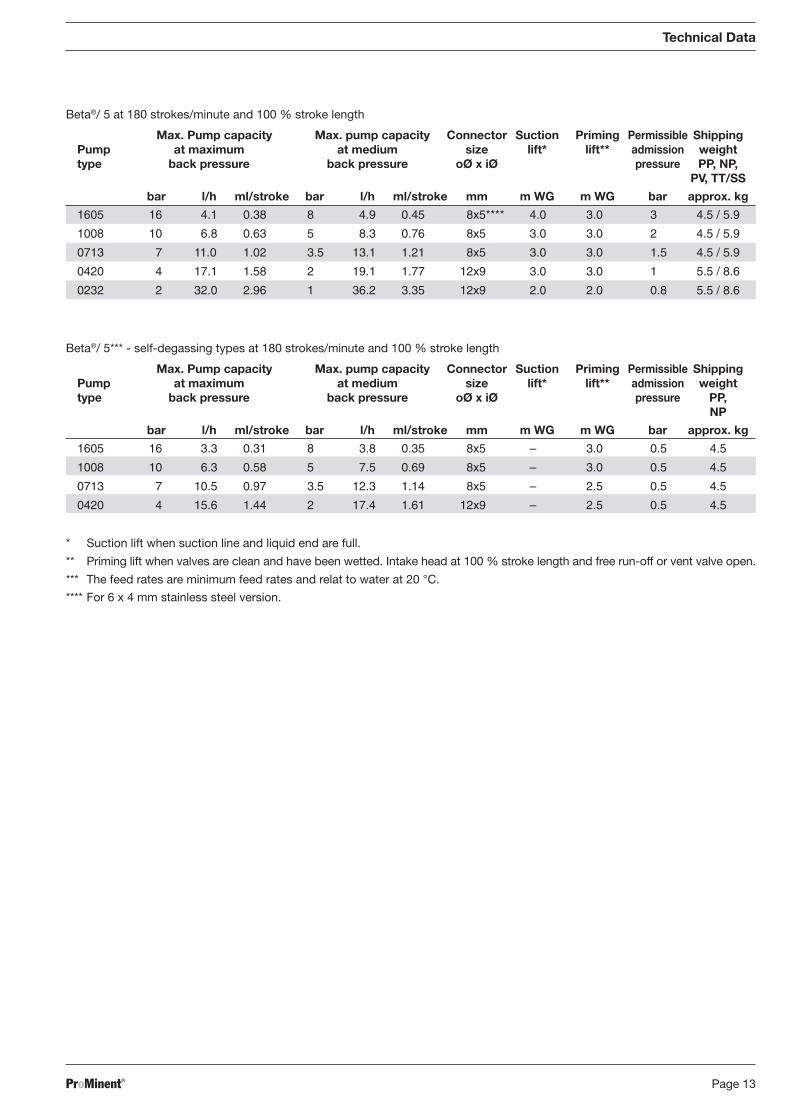
Beta®/ 5 at 180 strokes/minute and 100 % stroke length
Beta®/ 5*** - self-degassing types at 180 strokes/minute and 100 % stroke length
Max. Pump capacity Max. pump capacity Connector Suction Priming Permissible ShippingPump at maximum at medium size lift* lift** admission weighttype back pressure back pressure oØ x iØ pressure PP, NP,
PV, TT/SS
bar l/h ml/stroke bar l/h ml/stroke mm m WG m WG bar approx. kg
1605 16 4.1 0.38 8 4.9 0.45 8x5**** 4.0 3.0 3 4.5 / 5.9
1008 10 6.8 0.63 5 8.3 0.76 8x5 3.0 3.0 2 4.5 / 5.9
0713 7 11.0 1.02 3.5 13.1 1.21 8x5 3.0 3.0 1.5 4.5 / 5.9
0420 4 17.1 1.58 2 19.1 1.77 12x9 3.0 3.0 1 5.5 / 8.6
0232 2 32.0 2.96 1 36.2 3.35 12x9 2.0 2.0 0.8 5.5 / 8.6
Max. Pump capacity Max. pump capacity Connector Suction Priming Permissible ShippingPump at maximum at medium size lift* lift** admission weighttype back pressure back pressure oØ x iØ pressure PP,
NP
bar l/h ml/stroke bar l/h ml/stroke mm m WG m WG bar approx. kg
1605 16 3.3 0.31 8 3.8 0.35 8x5 – 3.0 0.5 4.5
1008 10 6.3 0.58 5 7.5 0.69 8x5 – 3.0 0.5 4.5
0713 7 10.5 0.97 3.5 12.3 1.14 8x5 – 2.5 0.5 4.5
0420 4 15.6 1.44 2 17.4 1.61 12x9 – 2.5 0.5 4.5
BA_BE_021_07_08_GB2.p65 17.07.2008, 14:35 Uhr13
ProMinent®Page 14
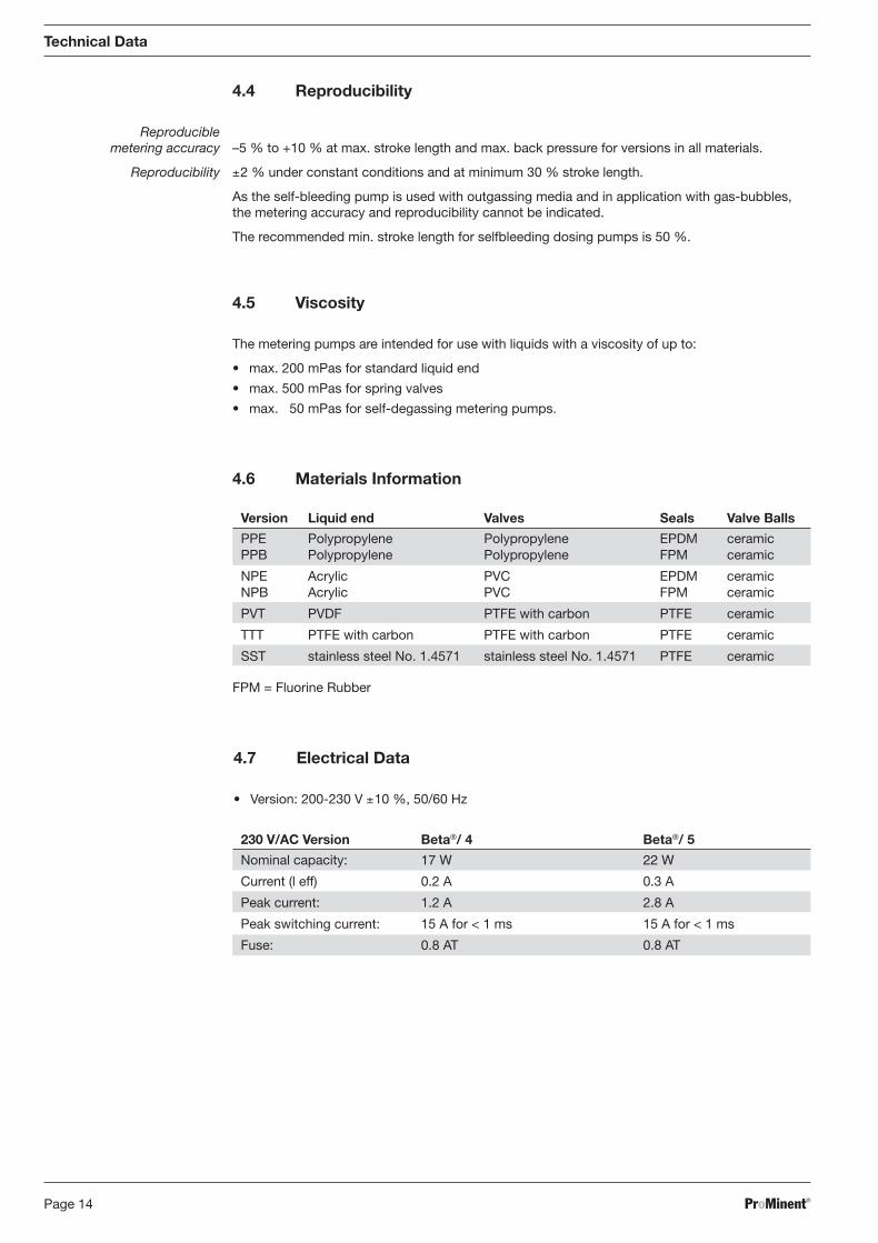
4.4 Reproducibility
Reproduciblemetering accuracy –5 % to +10 % at max. stroke length and max. back pressure for versions in all materials.
Reproducibility ±2 % under constant conditions and at minimum 30 % stroke length.
As the self-bleeding pump is used with outgassing media and in application with gas-bubbles,the metering accuracy and reproducibility cannot be indicated.
The recommended min. stroke length for selfbleeding dosing pumps is 50 %.
4.5 Viscosity
The metering pumps are intended for use with liquids with a viscosity of up to:
• max. 200 mPas for standard liquid end
• max. 500 mPas for spring valves
• max. 50 mPas for self-degassing metering pumps.
4.6 Materials Information
Technical Data
4.7 Electrical Data
• Version: 200-230 V ±10 %, 50/60 Hz
FPM = Fluorine Rubber
230 V/AC Version Beta®/ 4 Beta®/ 5
Nominal capacity: 17 W 22 W
Current (l eff) 0.2 A 0.3 A
Peak current: 1.2 A 2.8 A
Peak switching current: 15 A for < 1 ms 15 A for < 1 ms
Fuse: 0.8 AT 0.8 AT
Version Liquid end Valves Seals Valve Balls
PPE Polypropylene Polypropylene EPDM ceramicPPB Polypropylene Polypropylene FPM ceramic
NPE Acrylic PVC EPDM ceramicNPB Acrylic PVC FPM ceramic
PVT PVDF PTFE with carbon PTFE ceramic
TTT PTFE with carbon PTFE with carbon PTFE ceramic
SST stainless steel No. 1.4571 stainless steel No. 1.4571 PTFE ceramic
BA_BE_021_07_08_GB2.p65 17.07.2008, 14:35 Uhr14

ProMinent® Page 15
4.8 Environmental Conditions
Temperatures Storage and transport temperature: –10 °C ... +50 °C
Maximum dosing media temperatures depending on material:
Technical Data
• Version: 100-115 V ±10 %, 50/60 Hz
Under extreme conditions such as max. medium temperature, max. stroke rate and max.backpressure leaks may occur at the liquid end at ambient temperatures above 35 °C.
Climate Permissible relative humidity: 92 % non-condensingCorresponding to humidityand fluctuations in climate: FW 24 according to DIN 50016
Enclosure rating Contact and humidity enclosure: IP 65 according to IEC 529, EN 60529, DIN VDE 0470 part 1
Noise level Noise level: < 70 dB(A) within 1 m distance according to EN 12639
Electrical safety requirements Safety class 1 – mains connector with earth lead
115 V/AC Version Beta®/ 4 Beta®/ 5
Nominal capacity: 17 W 22 W
Current (l eff) 0.5 A 0.8 A
Peak current: 4.0 A 6.5 A
Peak switching current: 15 A for < 1 ms 15 A for < 1 ms
Fuse: 0.8 AT 0.8 AT
• Version: 100-230 V ±10 %, 50/60 Hz
Note Only use fuses carrying VDE, UL and CSA authorisation, e.g. type 19195 from Fa. Wickmannas given in IEC publication 127 - 2/3.
Material Type: PP PVC Acrylic PVDF PTFE Stainlesssteel
Permissible temperature continuousoperation at max. back pressure: 50 °C 45 °C* 45 °C 50 °C 50 °C 50 °C
Permissible temperature short term,max. 15 min. operation at max.back pressure of 2 bar: 100 °C 60 °C 60 °C 120 °C 120 °C 120 °C
Minimum dosing media temperature: -10°Cambient temperature during operation: -10 through +45°C*
*for material acrylic glass
100-230 V/AC Version Beta®/ 4 Beta®/ 5
Nominal capacity: 17 W 22 W
Current (l eff) 0.5 … 0.2 A 0.8 … 0.3 A
Peak current: 4.2 - 1.3 A 5.9 - 2.3 A
Peak switching current: 15 A for < 1 ms 15 A for < 1 ms
Fuse: 0.8 AT 0.8 AT
BA_BE_021_07_08_GB2.p65 17.07.2008, 14:35 Uhr15
ProMinent®Page 16
6 Electrical Installation
WARNING
• WARNING – Risk of electric shock – This pump is supplied with a grounding conductorand grounding-type attachment plug. To reduce the risk of electric shock, be certainthat it is connected only to a properly grounding-type receptacle.
• Observe the relevant national regulations when installing the pump outside Germany!
• Do not connect power supply to external terminals!
• Make sure that the power supply corresponds to the details on the device label!When connecting in parallel with inductive consumers a separate switch contact,e.g. relay or coutactor should be fitted!
CAUTION
• The electronic system of the pump can be destroyed if the pump is connected incorrectly!When connecting the 5P universal control cable for external contact control, do notconnect the grey wire instead of the white one! At first, the pump functions without anyfaults, however, the electronic system of the pump will be destroyed after approx.10 million strokes!
• The universal signal cable, the external/contact cable and the liquid level monitoringcable may not be less than 1.20 m. Cable recognition will otherwise be lost.
Mains connection The pump is connected via the fixed mains cable to the correct power supply.
ON/Off switching The pump should only be able to be disconnected from the power by
• removing the plug from the socket
• via the ”stop“ setting on the multifunction switch
• remote stop via an external cable (see 7.1).
Connecting in parallel If the pump is connected to the power in parallel with inductive consumers, e.g. (solenoid valve,motor), they must be electrically isolated from these items to prevent damage from inductionvoltages when switching off.
Fit separate contacts, power supply via contacter relay or relay.
If this is not possible, then: Parallel connection via varistor (order number 710912) or an RC circuit
(0.22 µF/220 Ω, order number 710802).
5 Removal of Packaging
Removal of packaging Retain the packaging. It can be used to return the pump in case of repair or for guaranteepurposes.
Compare delivery note with contents of packaging.
Check that the details given on the metering pump device label correspond with your orderingdetails!
Should you experience any problems, contact your ProMinent branch or supplier!
Give the identity code and serial number, which you will find on the device label, in the eventof goods returns or when ordering replacement parts. This will ensure correct identification ofthe pump type and material version.
Included in Delivery • Metering pump with mains cable
• Operating instructions manual with conformity declaration, with accessories if applicable
Removal of Packaging / Electrical Installation
BA_BE_021_07_08_GB2.p65 17.07.2008, 14:35 Uhr16
ProMinent® Page 17
Electrical Installation
1
PEL1N
2
45
3
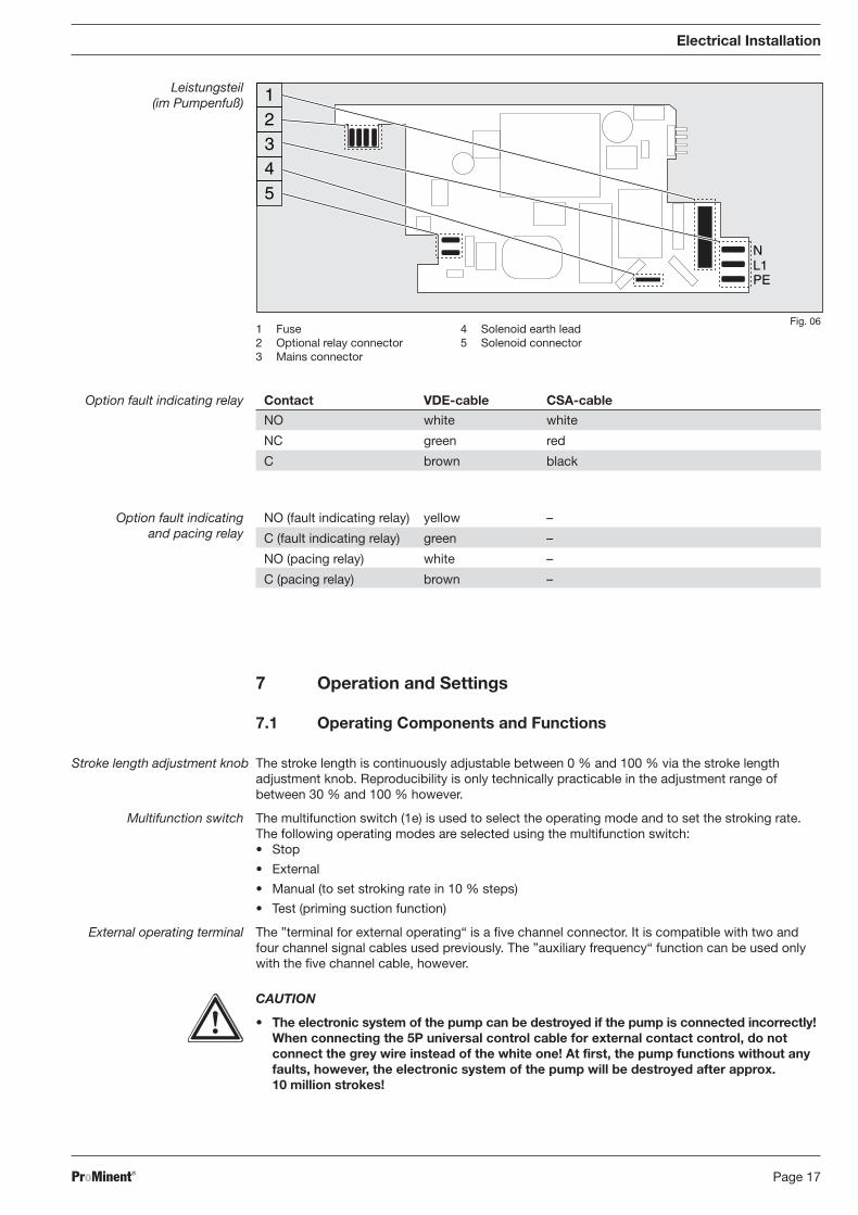
Fig. 061 Fuse2 Optional relay connector3 Mains connector
4 Solenoid earth lead5 Solenoid connector
Leistungsteil(im Pumpenfuß)
Option fault indicating relay Contact VDE-cable CSA-cable
NO white white
NC green red
C brown black
Option fault indicating NO (fault indicating relay) yellow –and pacing relay C (fault indicating relay) green –
NO (pacing relay) white –
C (pacing relay) brown –
7 Operation and Settings
7.1 Operating Components and Functions
Stroke length adjustment knob The stroke length is continuously adjustable between 0 % and 100 % via the stroke lengthadjustment knob. Reproducibility is only technically practicable in the adjustment range ofbetween 30 % and 100 % however.
Multifunction switch The multifunction switch (1e) is used to select the operating mode and to set the stroking rate.The following operating modes are selected using the multifunction switch:• Stop
• External
• Manual (to set stroking rate in 10 % steps)
• Test (priming suction function)
External operating terminal The ”terminal for external operating“ is a five channel connector. It is compatible with two andfour channel signal cables used previously. The ”auxiliary frequency“ function can be used onlywith the five channel cable, however.
CAUTION
• The electronic system of the pump can be destroyed if the pump is connected incorrectly!When connecting the 5P universal control cable for external contact control, do notconnect the grey wire instead of the white one! At first, the pump functions without anyfaults, however, the electronic system of the pump will be destroyed after approx.10 million strokes!
BA_BE_021_07_08_GB2.p65 17.07.2008, 14:35 Uhr17
ProMinent®Page 18
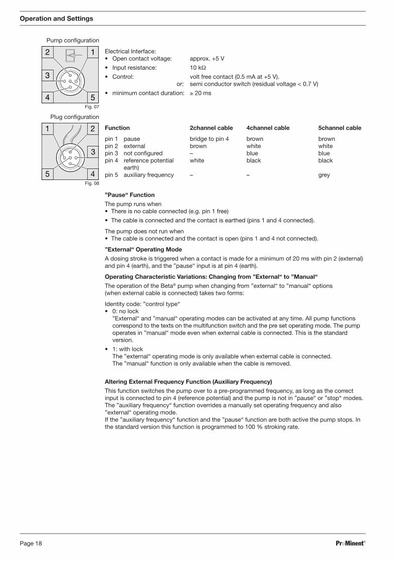
Pump configuration
Electrical Interface:• Open contact voltage: approx. +5 V
• Input resistance: 10 kΩ
• Control: volt free contact (0.5 mA at +5 V).or: semi conductor switch (residual voltage < 0.7 V)
• minimum contact duration: ≥ 20 ms
Plug configuration
Function 2channel cable 4channel cable 5channel cable
pin 1 pause bridge to pin 4 brown brownpin 2 external brown white whitepin 3 not configured – blue bluepin 4 reference potential white black black
earth)pin 5 auxiliary frequency – – grey
”Pause“ Function
The pump runs when• There is no cable connected (e.g. pin 1 free)
• The cable is connected and the contact is earthed (pins 1 and 4 connected).
The pump does not run when• The cable is connected and the contact is open (pins 1 and 4 not connected).
”External“ Operating Mode
A dosing stroke is triggered when a contact is made for a minimum of 20 ms with pin 2 (external)and pin 4 (earth), and the ”pause“ input is at pin 4 (earth).
Operating Characteristic Variations: Changing from ”External“ to ”Manual“
The operation of the Beta® pump when changing from ”external“ to ”manual“ options(when external cable is connected) takes two forms:
Identity code: ”control type“• 0: no lock
”External“ and ”manual“ operating modes can be activated at any time. All pump functionscorrespond to the texts on the multifunction switch and the pre set operating mode. The pumpoperates in ”manual“ mode even when external cable is connected. This is the standardversion.
• 1: with lockThe ”external“ operating mode is only available when external cable is connected.The ”manual“ function is only available when the cable is removed.
Altering External Frequency Function (Auxiliary Frequency)
This function switches the pump over to a pre-programmed frequency, as long as the correctinput is connected to pin 4 (reference potential) and the pump is not in ”pause“ or ”stop“ modes.The ”auxiliary frequency“ function overrides a manually set operating frequency and also”external“ operating mode.If the ”auxiliary frequency“ function and the ”pause“ function are both active the pump stops. Inthe standard version this function is programmed to 100 % stroking rate.
Operation and Settings
1
54
2
3
Fig. 07
Fig. 08
BA_BE_021_07_08_GB2.p65 17.07.2008, 14:35 Uhr18

ProMinent® Page 19
Operation and Settings
3
21Fig. 09
Fig. 10
3
12
Connecting float switch It is possible to fit a two stage float switch to activate early warning and limit switch functions.
Pump configuration
Electrical Interface:• Open contact voltage: approx. +5 V• Input resistance: 10 kΩ• Control: volt free contact (0.5 mA at +5 V).
or: semi conductor switch (residual voltage < 0.7 V)
Plug configuration
Function 3channel cable
pin 1 reference potential (earth) blackpin 2 minimum warning indication bluepin 3 minimum fault (switches off) brown
Function and fault indicators A signal is sent to the pump (minimum warning or minimum fault) when the liquid level in thechemical feed tank drops below specific levels.
Three LED displays act as the function and fault indicators.
Green LED indicator, operating displayThis LED illuminates briefly when a discharge stroke is activated.
Yellow LED indicator, warning indicator
This LED lights up when the liquid level drops below the first float switch triggering level.
Red LED indicator, fault indicatorThis LED lights up when liquid levels reach the fault indicating level (20 mm remaining in chemicalfeed tank)It also flashes to indicate undefined operating status.
Relay
Relay output, fault indicating An alarm relay can be ordered as on option. It switches in case of faults. Whether it drops out orpicks up in case of fault was preselected via the Identcode.If the alarm relay is refitted, it drops out in case of fault as standard. The relay board is fullyoperative after insertion (see section 7.2).
Electrical interface: • Contact load: 250 V/2 A 50/60 Hz• Operating life: > 200.000 switch functions
VDE cable CSA cable Contact
white white NO (normally open)
green red NC (normally closed)
brown black C (common)
Fault signal output Two semi conductor switches are available to order as signal output and pacing relay.and pacing signal output These outputs are electrically isolated by optical couplers.
The pulse output of the pump drives an open collector transistor interfaced to the input device.This option may be retrofitted, the connector cable is plugged in.
Electrical interface: For semi-conductor switch For relay output• Residual voltage: < 0.4 Volt at IC = 1 mA • Contact load:• Maximum current: < 100 mA 24 V/100 mA 50/60 Hz• Max. voltage: 24 V DC • Operating life:• Pacing relay pulse length approx. 100 ms > 200.000 switch functions
BA_BE_021_07_08_GB2.p65 17.07.2008, 14:35 Uhr19

ProMinent®Page 20
VDE cable Contact Relayyellow NO (normally open) Fault indicating relaygreen C (common) Fault indicating relaywhite NO (normally open) Pacing relaybrown C (common) Pacing relay
7.2 Beta® Relay Retrofit Kit
Part No. 1002526 - Alarm relay Beta®
Part No. 1002528 - Alarm and pacing relay Beta®
1 complete relay board with 2 fastening screws2 additional fastening screws1 complete relay cable with socket1 seal
Press-out relayopening
WARNING
Disconnect Beta® from the mains power supply and rinse liquid end before commencingwork!
CAUTION
When preparing the opening, ensure that the punch is not forced through the entire pumpbase!Pump circuits may become damaged.
Place the Beta® on a firm surface with the relay opening press-out section at the top.(see fig. 11a)
Place a punch (dia. 8-15 mm) in the centre of the relay opening press-out section, and strikebriefly and sharply with a hammer (approx. 250 g).
If necessary clean up the edges of the opening.
Remove the pressed out section from the Beta®.
Inserting the relay component Hold the relay component with your right hand gripping the left and right hand edges of therelay cover, and tilt the front end slightly to the left (see fig. 11b)
Push the relay component through the relay opening, holding the upper corner of the lower edgeagainst the guide rail on the pump base, until the contact of the relay component has reachedthe controller contact. (See fig. 11b test: can you still move the end of the circuit back and forth?)
Gently push the relay component right into the opening.
Screw the relay cover firmly onto the housing using the screws provided.
Insert the relay cable plug seal into the relay cover and screw on the plug (see IIc).
The pump is programmed ex factory to “alarm relay drop-out action” and, if fitted,“pacing relay pick-up action“. The pump can be reprogrammed at the Heidelberg plantif any other switching function is required.
Operation and Settings
a Fig. 11 b c
BA_BE_021_07_08_GB2.p65 17.07.2008, 14:35 Uhr20
ProMinent® Page 21
Operation and Settings
0
1
2
3
4
5
6
0% 10% 20% 30% 40% 50% 60% 70% 80% 90% 100%
0
0.2
0.4
0.6
0.8
1
1.2
1 2 4 5 8 10
0
0.5
1
1.5
1 2 4 6 8 11 13 16
0
0.5
1
1.5
2
2.5
3
0% 10% 20% 30% 40% 50% 60% 70% 80% 90% 100%
0
0.2
0.4
0.6
0.8
1
1.2
1.4
1.6
0% 10% 20% 30% 40% 50% 60% 70% 80% 90% 100%
0
0.5
1
1.5
1 2 4 6 8 11 13 16
0
0.1
0.2
0.3
0.4
0.5
0.6
0.7
0.8
0.9
0% 10% 20% 30% 40% 50% 60% 70% 80% 90% 100%
00.20.40.60.8
11.21.41.6
1 2 4 5 6 8 10
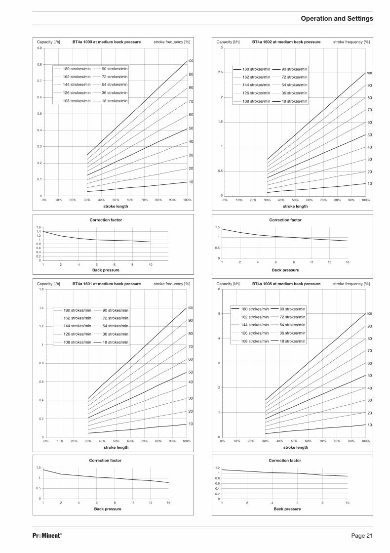
Capacity [l/h] stroke frequency [%]BT4a 1000 at medium back pressure
stroke length
Back pressure
180 strokes/min
162 strokes/min
144 strokes/min
126 strokes/min
108 strokes/min
Correction factor
90 strokes/min
72 strokes/min
54 strokes/min
36 strokes/min
18 strokes/min
180 strokes/min
162 strokes/min
144 strokes/min
126 strokes/min
108 strokes/min
90 strokes/min
72 strokes/min
54 strokes/min
36 strokes/min
18 strokes/min
Capacity [l/h] stroke frequency [%]BT4a 1601 at medium back pressure
stroke length
Back pressure
Correction factor
100
90
80
Capacity [l/h] stroke frequency [%]BT4a 1602 at medium back pressure
stroke length
Back pressure
180 strokes/min
162 strokes/min
144 strokes/min
126 strokes/min
108 strokes/min
Correction factor
90 strokes/min
72 strokes/min
54 strokes/min
36 strokes/min
18 strokes/min
Capacity [l/h] stroke frequency [%]BT4a 1005 at medium back pressure
stroke length
Back pressure
Correction factor
180 strokes/min
162 strokes/min
144 strokes/min
126 strokes/min
108 strokes/min
90 strokes/min
72 strokes/min
54 strokes/min
36 strokes/min
18 strokes/min
70
60
50
40
30
20
10
100
90
80
70
60
50
40
30
20
10
100
90
80
70
60
50
40
30
20
10
100
90
80
70
60
50
40
30
20
10
BA_BE_021_07_08_GB2.p65 17.07.2008, 14:35 Uhr21

ProMinent®Page 22
Operation and Settings
0
0.5
1
1.5
2
1 2 4 6 8 11 13 16
0
1
2
3
4
5
6
0% 10% 20% 30% 40% 50% 60% 70% 80% 90% 100%
0.8
0.85
0.9
0.95
1
1.05
0.5 1 1.5 2
0
5
10
15
20
25
0% 10% 20% 30% 40% 50% 60% 70% 80% 90% 100%
0
0.2
0.4
0.6
0.8
1
1.2
1 1.5 2 3 4
0
2
4
6
8
10
12
14
16
0% 10% 20% 30% 40% 50% 60% 70% 80% 90% 100%
0
0.2
0.4
0.6
0.8
1
1.2
1 2 3.5 4 6 7
0
1
2
3
4
5
6
7
8
9
0% 10% 20% 30% 40% 50% 60% 70% 80% 90% 100%
Capacity [l/h] stroke frequency [%]BT4a 0708 at medium back pressure
stroke length
Back pressure
180 strokes/min
162 strokes/min
144 strokes/min
126 strokes/min
108 strokes/min
Correction factor
90 strokes/min
72 strokes/min
54 strokes/min
36 strokes/min
18 strokes/min
180 strokes/min
162 strokes/min
144 strokes/min
126 strokes/min
108 strokes/min
90 strokes/min
72 strokes/min
54 strokes/min
36 strokes/min
18 strokes/min
Capacity [l/h] stroke frequency [%]BT4a 0413 at medium back pressure
stroke length
Back pressure
Correction factor
100
90
80
Capacity [l/h] stroke frequency [%]BT4a 0220 at medium back pressure
stroke length
Back pressure
180 strokes/min
162 strokes/min
144 strokes/min
126 strokes/min
108 strokes/min
Correction factor
90 strokes/min
72 strokes/min
54 strokes/min
36 strokes/min
18 strokes/min
Capacity [l/h] stroke frequency [%]BT5a 1605 at medium back pressure
stroke length
Back pressure
Correction factor
180 strokes/min
162 strokes/min
144 strokes/min
126 strokes/min
108 strokes/min
90 strokes/min
72 strokes/min
54 strokes/min
36 strokes/min
18 strokes/min
70
60
50
40
30
20
10
100
90
80
70
60
50
40
30
20
10
100
90
80
70
60
50
40
30
20
10
100
90
80
70
60
50
40
30
20
10
BA_BE_021_07_08_GB2.p65 17.07.2008, 14:35 Uhr22
ProMinent® Page 23
Operation and Settings
0
0.2
0.4
0.6
0.8
1
1.2
0.5 1 1.5 2
0
5
10
15
20
25
30
35
40
0% 10% 20% 30% 40% 50% 60% 70% 80% 90% 100%
0
5
10
15
20
25
0% 10% 20% 30% 40% 50% 60% 70% 80% 90% 100%
0
0.2
0.4
0.6
0.8
1
1.2
1 1.5 2 3 4
0
0.2
0.4
0.6
0.8
1
1.2
1 2 3.5 4 6 7
0
2
4
6
8
10
12
14
0% 10% 20% 30% 40% 50% 60% 70% 80% 90% 100%
00.20.40.60.8
11.21.4
1 2 3.5 5 6 10
0
1
2
3
4
5
6
7
8
9
0% 10% 20% 30% 40% 50% 60% 70% 80% 90% 100%
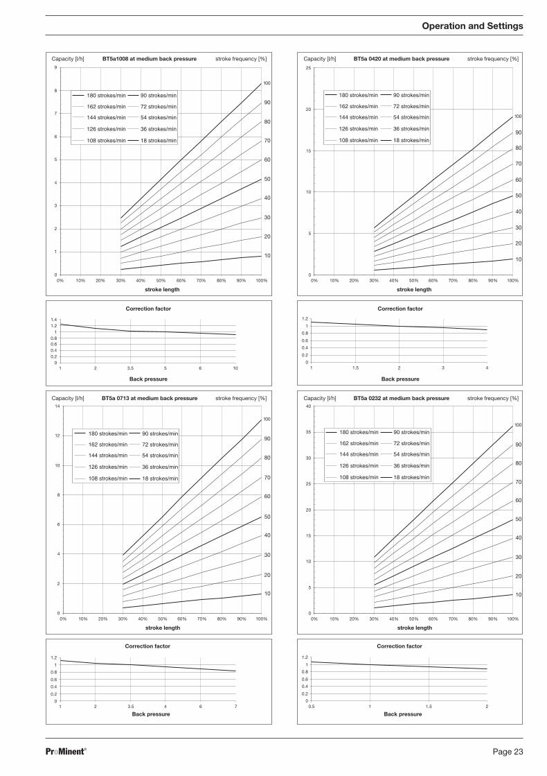
Capacity [l/h] stroke frequency [%]BT5a1008 at medium back pressure
stroke length
Back pressure
180 strokes/min
162 strokes/min
144 strokes/min
126 strokes/min
108 strokes/min
Correction factor
90 strokes/min
72 strokes/min
54 strokes/min
36 strokes/min
18 strokes/min
180 strokes/min
162 strokes/min
144 strokes/min
126 strokes/min
108 strokes/min
90 strokes/min
72 strokes/min
54 strokes/min
36 strokes/min
18 strokes/min
Capacity [l/h] stroke frequency [%]BT5a 0713 at medium back pressure
stroke length
Back pressure
Correction factor
100
90
80
Capacity [l/h] stroke frequency [%]BT5a 0420 at medium back pressure
stroke length
Back pressure
180 strokes/min
162 strokes/min
144 strokes/min
126 strokes/min
108 strokes/min
Correction factor
90 strokes/min
72 strokes/min
54 strokes/min
36 strokes/min
18 strokes/min
Capacity [l/h] stroke frequency [%]BT5a 0232 at medium back pressure
stroke length
Back pressure
Correction factor
180 strokes/min
162 strokes/min
144 strokes/min
126 strokes/min
108 strokes/min
90 strokes/min
72 strokes/min
54 strokes/min
36 strokes/min
18 strokes/min
70
60
50
40
30
20
10
100
90
80
70
60
50
40
30
20
10
100
90
80
70
60
50
40
30
20
10
100
90
80
70
60
50
40
30
20
10
BA_BE_021_07_08_GB2.p65 17.07.2008, 14:35 Uhr23

ProMinent®Page 24
8 Maintenance
Maintenance intervals • Every quarter, when subject to normal usage (continuous operation - approx. 30 %).
• Shorter intervals when subject to heavier usage (e.g. continuous operation).
Maintenance actions Standard liquid ends:
Check the diaphragm for damage (see section 9).
Check chemical seepage at vent hole.
Check that the discharge tubing is connected firmly to the liquid end.
Check that discharge and suction valves are firmly fixed.
Check that the liquid end is generally watertight (especially vent hole! See fig. 13).
Check for correct feed: run the Beta® run for a short period (press both arrow keys together).
Check electrical connections for wear.
Check that liquid end screws are fastened tightly (on coarse/fine bleeding versions, firstremove knob and cover.
Screw fastening torque: 4.5 to 5 Nm
NOTE
• For PP liquid end, check fastening torque every quarter!
Additionally, for liquid ends with coarse/fine bleed function and SEK type:
• Check that the bypass tubing is connected firmly to the liquid end
• Check that the bleed valve is firmly fixed in place
• Examine the discharge and bypass tubing for kinks
• Check that the coarse/fine bleed function is working correctly
Maintenance / Repairs
9 Repairs
NOTE
Repair work that may be carried out by authorised personnel only, or on factory premises:
• Replacement of damaged mains cables.
• Replacement of fuses and electronic controller.
Please contact your nearest ProMinent branch or representative!
Only send the equipment for repair or maintenance in a cleaned condition and with the liquid endflushed. However, should any safety precautions be necessary even after careful draining andcleaning of the equipment, the required information must be listed in the Safety Declaration!The Safety Declaration forms part of the inspection/repair contract.Maintenance or repair work will only be carried out if a Safety Declaration - correctly and fullycompleted by an authorised and qualified member of the Operator's staff - is available.
A copy of the form is included in the “General operating instructions for ProMinent solenioddosing pumps” or can be downloaded at www.prominent.com.
Fig. 13
Vent hole
BA_BE_021_07_08_GB2.p65 17.07.2008, 14:35 Uhr24
ProMinent® Page 25
WARNING
Pumps used for radioactive materials cannot be returned to ProMinent after use! They willnot be accepted by ProMinent!
Repairs: These should only be carried out by qualified personnel (in accordance with Safetysection):
• Cleaning the valve
• Changing the diaphragm
WARNING
• Always take suitable precautions when using hazardous chemicals!
• Ensure equipment is de-pressurised.
NOTE
Take the exploded drawings annexed to the help.
Cleaning the discharge valve (PP, NP) for types 1000, 1005, 1605, 1601, 1602
NOTE
• Discharge and suction valves are different! Dismantle one after the other to avoidconfusion.
• Only use new parts, which fit your valve (in shape and chemical resistance)!
• The pump must be reset after replacing a valve.
• Insert an Allen key or similar into the smaller hole of the pressure connector and pushout the valve inserts.
Cleaning the suction valve (PP, NP) for types 1000, 1005, 1605, 1601, 1602
A suction valve is designed almost similar to a pressure valve.
Take care however that:
• both valve inserts are actually identical,
• an additional spacer is found under the valve inserts,
• in the liquid end a shaped seal 1 is used instead of an O-ring,
• the flow direction of the suction connection is reversed as for the pressure connector.
Cleaning the discharge valve (PP, PC, NP) for types 0708, 1008, 0220, 0420, 0413, 0713, 0232
NOTE
• Discharge and suction valves are different! Dismantle one after the other to avoidconfusion!
• Only use new parts, which fit your valve (in shape and chemical resistance)!
• The pump must be reset after replacing a valve.
• Insert an Allen key or similar into the smaller hole of the pressure connector and pushout the valve inserts.
Cleaning the suction valve (PP, NP) for types 0708, 1008, 0220, 0420, 0413, 0713, 0232
A suction valve is designed almost similar to a pressure valve. Please ensure, however, that:
• the shaped seal is placed in the suction connector,
• only the O-ring is inserted into the liquid end and not the shaped seal,
• the flow direction for the suction connector is reversed as for the pressure connector.
Repairs
BA_BE_021_07_08_GB2.p65 17.07.2008, 14:35 Uhr25

ProMinent®Page 26
Change diaphragm WARNING
• Always take suitable precautions when using hazardous chemicals!
• Ensure that the equipment is de-pressurised!
Empty the liquid end (turn the unit upside down and let the feed chemical run out, rinse with asuitable material: rinse the liquid end thoroughly after use with hazardous materials!).
When Beta® is running set the stroke length to 0 % (the drive axis is then set).
Switch off the Beta®.
Unscrew the hydraulic connectors from the discharge and suction side.
For versions with coarse/fine bleed function: firstly pull out the coarse/fine bleed (knob), then liftoff the cover from the liquid end using a screwdriver.
Remove the screws (1).
For pump types 0220, 0232 and 0420 see the following page (4 holes on the diaphragm rim)!
Standard types Loosen the liquid end (2) and the top plate (4) from the pump housing (6) (loosen only!).
Hold the housing (6) in one hand and with the other, clamp the diaphragm (3) between theliquid end (2) and the top plate (4); release the diaphragm (3) from the drive spindle with a lightanticlockwise turn of the liquid end (2) and top plate (4).
Unscrew the diaphragm (3) completely from the drive spindle.
Remove the top plate (4) from the housing (6).
Check the condition of the safety diaphragm (5) and replace if necessary.
Push the safety diaphragm (5) onto the drive axle until the outer edge is flush with the pumphousing (6) - do not push further!
Screw the new diaphragm (3) carefully up to the stop on the drive axis – this must be exact toensure correct metering!
Screw the diaphragm (3) tight once more.
Position the top plate (4) on the pump housing (6).
CAUTION
• The leakage hole must point downwards when the pump is fully assembled (see fig. 13)
• Position the top plate correctly on the pump housing. Do not distort the top plate on thepump housing, otherwise the safety diaphragm (5) will not fit.
Lay the diaphragm (3) into the top plate (4).
Hold the top plate and screw the diaphragm (3) in a clockwise direction until it is firmly inposition (you will feel the resistance of the return spring).
CAUTION
• Do not overtighten the diaphragm (particularly on type 1601).
• The top plate must remain in position to prevent the safety diaphragm (5) from distorting.
Adjust the stroke to 100 %.
Position the liquid end (2) with the screws (1) on the diaphragm (3) and the top plate (4) (thepriming connector must point downwards once the pump is fully assembled). Screw on screws(1) lightly and tighten (starting torque, see below).
For versions with coarse/fine bleed function, ensure that the liquid end cover engages in theliquid end, then push the coarse/fine bleed vent (knob) into the liquid end.
Repairs
BA_BE_021_07_08_GB2.p65 17.07.2008, 14:35 Uhr26
ProMinent® Page 27
NOTE
• Check the screw torques after 24 hours in operation.
• For PP liquid ends check the screw torques again after three months.
Screw torques: 4.5 to 5 Nm
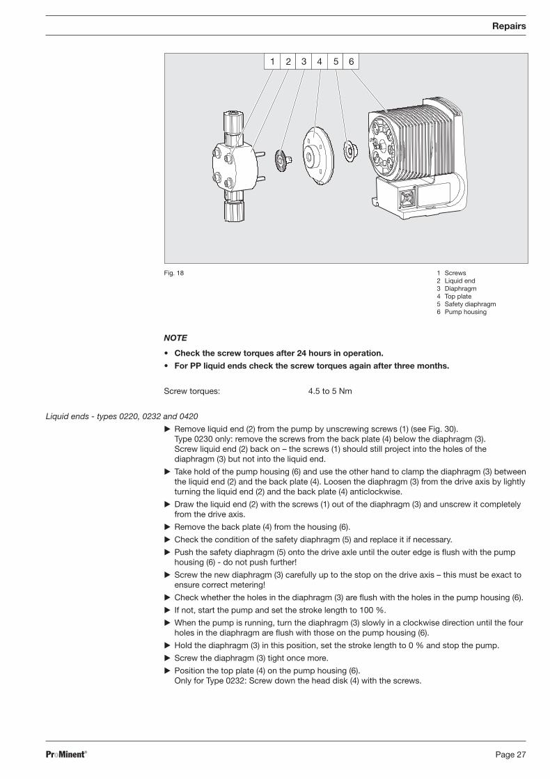
Liquid ends - types 0220, 0232 and 0420
Remove liquid end (2) from the pump by unscrewing screws (1) (see Fig. 30).Type 0230 only: remove the screws from the back plate (4) below the diaphragm (3).Screw liquid end (2) back on – the screws (1) should still project into the holes of thediaphragm (3) but not into the liquid end.
Take hold of the pump housing (6) and use the other hand to clamp the diaphragm (3) betweenthe liquid end (2) and the back plate (4). Loosen the diaphragm (3) from the drive axis by lightlyturning the liquid end (2) and the back plate (4) anticlockwise.
Draw the liquid end (2) with the screws (1) out of the diaphragm (3) and unscrew it completelyfrom the drive axis.
Remove the back plate (4) from the housing (6).
Check the condition of the safety diaphragm (5) and replace it if necessary.
Push the safety diaphragm (5) onto the drive axle until the outer edge is flush with the pumphousing (6) - do not push further!
Screw the new diaphragm (3) carefully up to the stop on the drive axis – this must be exact toensure correct metering!
Check whether the holes in the diaphragm (3) are flush with the holes in the pump housing (6).
If not, start the pump and set the stroke length to 100 %.
When the pump is running, turn the diaphragm (3) slowly in a clockwise direction until the fourholes in the diaphragm are flush with those on the pump housing (6).
Hold the diaphragm (3) in this position, set the stroke length to 0 % and stop the pump.
Screw the diaphragm (3) tight once more.
Position the top plate (4) on the pump housing (6).Only for Type 0232: Screw down the head disk (4) with the screws.
Repairs
1 2 3 4 5 6
Fig. 18 1 Screws2 Liquid end3 Diaphragm4 Top plate5 Safety diaphragm6 Pump housing
BA_BE_021_07_08_GB2.p65 17.07.2008, 14:35 Uhr27
ProMinent®Page 28
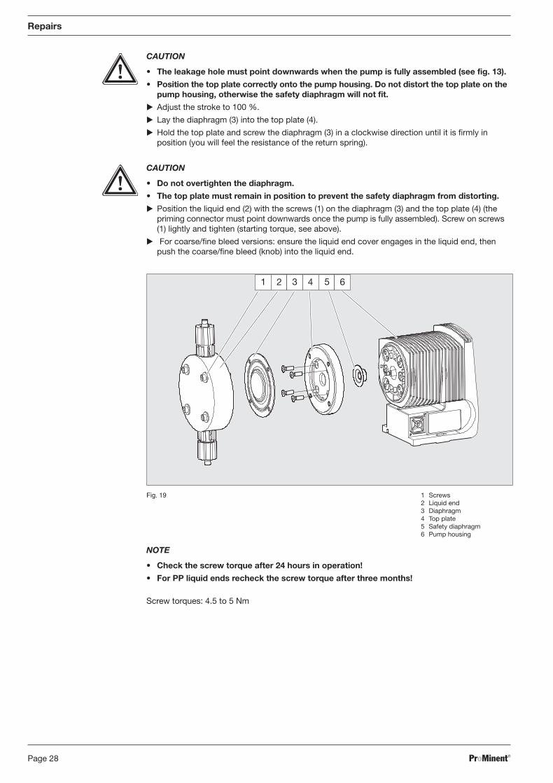
1 2 3 4 5 6
Fig. 19 1 Screws2 Liquid end3 Diaphragm4 Top plate5 Safety diaphragm6 Pump housing
CAUTION
• The leakage hole must point downwards when the pump is fully assembled (see fig. 13).
• Position the top plate correctly onto the pump housing. Do not distort the top plate on thepump housing, otherwise the safety diaphragm will not fit.
Adjust the stroke to 100 %.
Lay the diaphragm (3) into the top plate (4).
Hold the top plate and screw the diaphragm (3) in a clockwise direction until it is firmly inposition (you will feel the resistance of the return spring).
CAUTION
• Do not overtighten the diaphragm.
• The top plate must remain in position to prevent the safety diaphragm from distorting.
Position the liquid end (2) with the screws (1) on the diaphragm (3) and the top plate (4) (thepriming connector must point downwards once the pump is fully assembled). Screw on screws(1) lightly and tighten (starting torque, see above).
For coarse/fine bleed versions: ensure the liquid end cover engages in the liquid end, thenpush the coarse/fine bleed (knob) into the liquid end.
Repairs
NOTE
• Check the screw torque after 24 hours in operation!
• For PP liquid ends recheck the screw torque after three months!
Screw torques: 4.5 to 5 Nm
BA_BE_021_07_08_GB2.p65 17.07.2008, 14:35 Uhr28

ProMinent® Page 29
10 Troubleshooting
CAUTION
• Wear protective goggles and clothing when working with hazardous chemicals!
• Please observe the safety information sheets for dosing media!
• Always de-pressurise the liquid end prior to working on a pump!
Pump is not priming even at full stroke length, and open bleed valve.
Reason Crystalline deposits on the ball seat because valve has dried out.
Remedy Detach suction tubing from chemical feed container and rinse liquid end thoroughly.
If this fails, dismantle valves and clean.
Green LED display (operating display) not lit
Reason Power supply not connected, or incorrect power supply.
Remedy Connect to correct power supply according to the details on the device label.
Reason Fuse is defective.
Remedy Contact your ProMinent branch or supplier!
Yellow LED display (warning indicator) is lit
Reason Liquid level in the feed tank has reached the first float-switch trigger level.
Remedy Refill chemical tank.
Red LED display (fault indicator) is lit
Reason Liquid level in the feed tank has reached the fault float-switch trigger level (20 mm from empty).
Remedy Refill chemical tank.
Red LED display (fault indicator) is flashing
Reason Pump operating mode is undefined.
Remedy Select the required operating mode.
Liquid is leaking from back plate
Reason There is a faulty seal between the liquid end and the diaphragm.
Remedy Tighten screws in the liquid end.
If this fails, replace diaphragm.
11 Decommissioning, Dismantling and Disposal
NOTE
• When dismantling a pump, clean thoroughly, paying particular attention to the liquid endin order to remove all traces of chemicals and dirt.
• When disposing of a pump it must be broken down into separate material types. Allparts must be sent for recycling or for correct disposal according to current legal wastedisposal requirements.
Cleaned, chemical-free pumps may be returned to your ProMinent branch for disposal.
Troubleshooting / Decommissioning, Dismantling and Disposal
BA_BE_021_07_08_GB2.p65 17.07.2008, 14:35 Uhr29
ProMinent®Page 30
Exploded diagrams of liquid ends
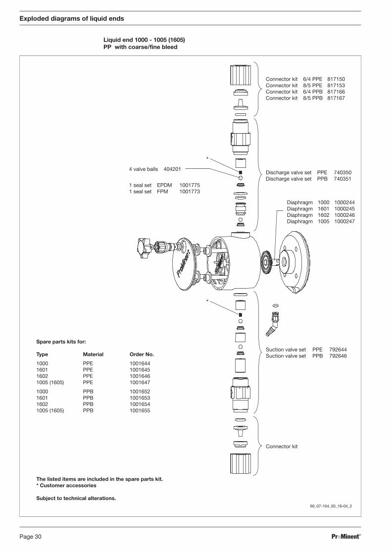
Liquid end 1000 - 1005 (1605)PP with coarse/fine bleed
*
*
60_07-104_00_18-04_2
Connector kit 6/4 PPE 817150Connector kit 8/5 PPE 817153Connector kit 6/4 PPB 817166Connector kit 8/5 PPB 817167
Discharge valve set PPE 740350Discharge valve set PPB 740351
Diaphragm 1000 1000244Diaphragm 1601 1000245Diaphragm 1602 1000246Diaphragm 1005 1000247
Suction valve set PPE 792644Suction valve set PPB 792646
Connector kit
4 valve balls 404201
1 seal set EPDM 10017751 seal set FPM 1001773
Spare parts kits for:
Type Material Order No.
1000 PPE 10016441601 PPE 10016451602 PPE 10016461005 (1605) PPE 1001647
1000 PPB 10016521601 PPB 10016531602 PPB 10016541005 (1605) PPB 1001655
The listed items are included in the spare parts kit.* Customer accessories
Subject to technical alterations.
BA_BE_021_07_08_GB2.p65 17.07.2008, 14:35 Uhr30
ProMinent® Page 31
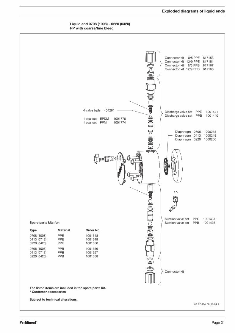
Discharge valve set PPE 1001441Discharge valve set PPB 1001440
Diaphragm 0708 1000248Diaphragm 0413 1000249Diaphragm 0220 1000250
Connector kit 8/5 PPE 817153Connector kit 12/9 PPE 817151Connector kit 8/5 PPB 817167Connector kit 12/9 PPB 817168
Suction valve set PPE 1001437Suction valve set PPB 1001436
Connector kit
Spare parts kits for:
Type Material Order No.
0708 (1008) PPE 10016480413 (0713) PPE 10016490220 (0420) PPE 1001650
0708 (1008) PPB 10016560413 (0713) PPB 10016570220 (0420) PPB 1001658
The listed items are included in the spare parts kit.* Customer accessories
Subject to technical alterations.
4 valve balls 404281
1 seal set EPDM 10017761 seal set FPM 1001774
Exploded diagrams of liquid ends
Liquid end 0708 (1008) - 0220 (0420)PP with coarse/fine bleed
*
*
60_07-104_00_19-04_2
BA_BE_021_07_08_GB2.p65 17.07.2008, 14:35 Uhr31
ProMinent®Page 32
Exploded diagrams of liquid ends
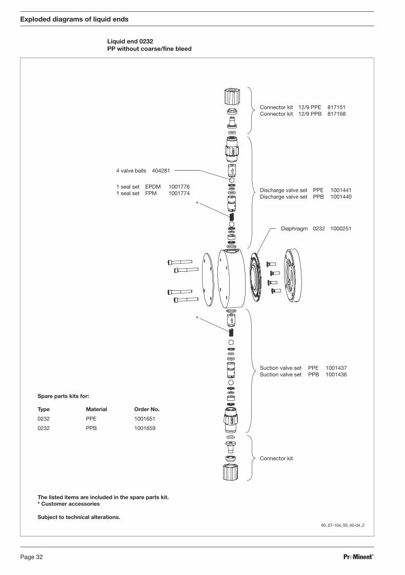
Liquid end 0232PP without coarse/fine bleed
*
*
60_07-104_00_40-04_2
Connector kit 12/9 PPE 817151Connector kit 12/9 PPB 817168
Discharge valve set PPE 1001441Discharge valve set PPB 1001440
Diaphragm 0232 1000251
Suction valve set PPE 1001437Suction valve set PPB 1001436
Connector kit
Spare parts kits for:
Type Material Order No.
0232 PPE 1001651
0232 PPB 1001659
The listed items are included in the spare parts kit.* Customer accessories
Subject to technical alterations.
4 valve balls 404281
1 seal set EPDM 10017761 seal set FPM 1001774
BA_BE_021_07_08_GB2.p65 17.07.2008, 14:35 Uhr32
ProMinent® Page 33
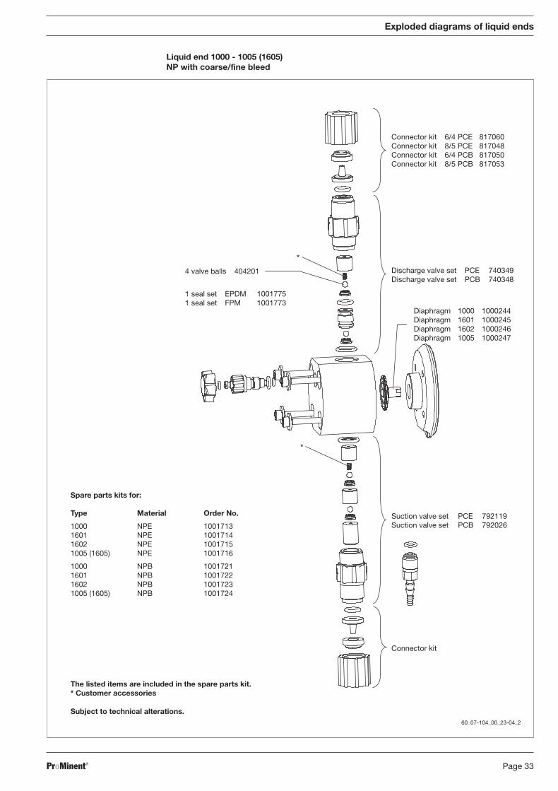
Exploded diagrams of liquid ends
Liquid end 1000 - 1005 (1605)NP with coarse/fine bleed
*
*
60_07-104_00_23-04_2
Connector kit 6/4 PCE 817060Connector kit 8/5 PCE 817048Connector kit 6/4 PCB 817050Connector kit 8/5 PCB 817053
Discharge valve set PCE 740349Discharge valve set PCB 740348
Diaphragm 1000 1000244Diaphragm 1601 1000245Diaphragm 1602 1000246Diaphragm 1005 1000247
Suction valve set PCE 792119Suction valve set PCB 792026
Connector kit
The listed items are included in the spare parts kit.* Customer accessories
Subject to technical alterations.
Spare parts kits for:
Type Material Order No.
1000 NPE 10017131601 NPE 10017141602 NPE 10017151005 (1605) NPE 1001716
1000 NPB 10017211601 NPB 10017221602 NPB 10017231005 (1605) NPB 1001724
4 valve balls 404201
1 seal set EPDM 10017751 seal set FPM 1001773
BA_BE_021_07_08_GB2.p65 17.07.2008, 14:35 Uhr33
ProMinent®Page 34
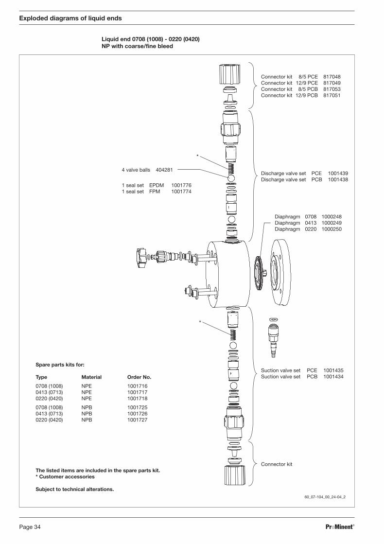
Exploded diagrams of liquid ends
Liquid end 0708 (1008) - 0220 (0420)NP with coarse/fine bleed
*
*
60_07-104_00_24-04_2
Connector kit 8/5 PCE 817048Connector kit 12/9 PCE 817049Connector kit 8/5 PCB 817053Connector kit 12/9 PCB 817051
Discharge valve set PCE 1001439Discharge valve set PCB 1001438
Diaphragm 0708 1000248Diaphragm 0413 1000249Diaphragm 0220 1000250
Suction valve set PCE 1001435Suction valve set PCB 1001434
Connector kitThe listed items are included in the spare parts kit.* Customer accessories
Subject to technical alterations.
Spare parts kits for:
Type Material Order No.
0708 (1008) NPE 10017160413 (0713) NPE 10017170220 (0420) NPE 1001718
0708 (1008) NPB 10017250413 (0713) NPB 10017260220 (0420) NPB 1001727
4 valve balls 404281
1 seal set EPDM 10017761 seal set FPM 1001774
BA_BE_021_07_08_GB2.p65 17.07.2008, 14:35 Uhr34
ProMinent® Page 35
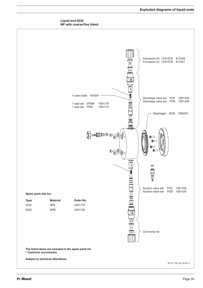
Exploded diagrams of liquid ends
Liquid end 0232NP with coarse/fine bleed
*
*
60_07-104_00_34-04_2
Connector kit 12/9 PCE 817049Connector kit 12/9 PCB 817051
Discharge valve set PCE 1001439Discharge valve set PCB 1001438
Diaphragm 0232 1000251
Suction valve set PCE 1001435Suction valve set PCB 1001434
Connector kit
Spare parts kits for:
Type Material Order No.
0232 NPE 1001719
0232 NPB 1001728
The listed items are included in the spare parts kit.* Customer accessories
Subject to technical alterations.
4 valve balls 404281
1 seal set EPDM 10017761 seal set FPM 1001774
BA_BE_021_07_08_GB2.p65 17.07.2008, 14:35 Uhr35
ProMinent®Page 36
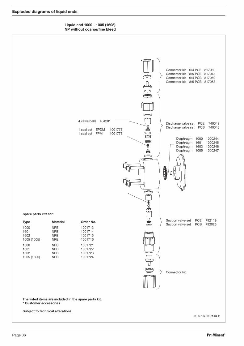
Exploded diagrams of liquid ends
Liquid end 1000 - 1005 (1605)NP without coarse/fine bleed
*
*
60_07-104_00_21-04_2
Connector kit 6/4 PCE 817060Connector kit 8/5 PCE 817048Connector kit 6/4 PCB 817050Connector kit 8/5 PCB 817053
Discharge valve set PCE 740349Discharge valve set PCB 740348
Diaphragm 1000 1000244Diaphragm 1601 1000245Diaphragm 1602 1000246Diaphragm 1005 1000247
Suction valve set PCE 792119Suction valve set PCB 792026
Connector kit
4 valve balls 404201
1 seal set EPDM 10017751 seal set FPM 1001773
Spare parts kits for:
Type Material Order No.
1000 NPE 10017131601 NPE 10017141602 NPE 10017151005 (1605) NPE 1001716
1000 NPB 10017211601 NPB 10017221602 NPB 10017231005 (1605) NPB 1001724
The listed items are included in the spare parts kit.* Customer accessories
Subject to technical alterations.
BA_BE_021_07_08_GB2.p65 17.07.2008, 14:35 Uhr36
ProMinent® Page 37
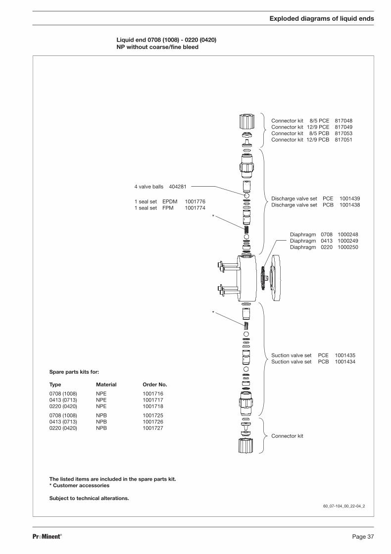
Exploded diagrams of liquid ends
Liquid end 0708 (1008) - 0220 (0420)NP without coarse/fine bleed
*
*
60_07-104_00_22-04_2
Connector kit 8/5 PCE 817048Connector kit 12/9 PCE 817049Connector kit 8/5 PCB 817053Connector kit 12/9 PCB 817051
Discharge valve set PCE 1001439Discharge valve set PCB 1001438
Diaphragm 0708 1000248Diaphragm 0413 1000249Diaphragm 0220 1000250
Suction valve set PCE 1001435Suction valve set PCB 1001434
Connector kit
Spare parts kits for:
Type Material Order No.
0708 (1008) NPE 10017160413 (0713) NPE 10017170220 (0420) NPE 1001718
0708 (1008) NPB 10017250413 (0713) NPB 10017260220 (0420) NPB 1001727
4 valve balls 404281
1 seal set EPDM 10017761 seal set FPM 1001774
The listed items are included in the spare parts kit.* Customer accessories
Subject to technical alterations.
BA_BE_021_07_08_GB2.p65 17.07.2008, 14:35 Uhr37

ProMinent®Page 38
Exploded diagrams of liquid ends
Liquid end 0232NP without coarse/fine bleed
*
*
60_07-104_00_20-04_2
Connector kit 12/9 PCE 817049Connector kit 12/9 PCB 817051
Discharge valve set PCE 1001439Discharge valve set PCB 1001438
Diaphragm 0232 1000251
Connector kit
Suction valve set PCE 1001435Suction valve set PCB 1001434
Spare parts kits for:
Type Material Order No.
0232 NPE 1001719
0232 NPB 1001728
4 valve balls 404281
1 seal set EPDM 10017761 seal set FPM 1001774
The listed items are included in the spare parts kit.* Customer accessories
Subject to technical alterations.
BA_BE_021_07_08_GB2.p65 17.07.2008, 14:35 Uhr38
ProMinent® Page 39
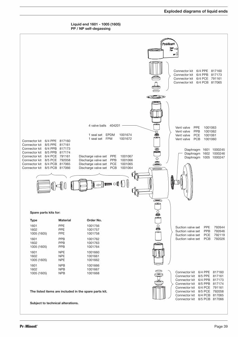
Exploded diagrams of liquid ends
Liquid end 1601 - 1005 (1605)PP / NP self-degassing
Connector kit 6/4 PPE 817160Connector kit 6/4 PPB 817173Connector kit 6/4 PCE 791161Connector kit 6/4 PCB 817065
Vent valve PPE 1001063Vent valve PPB 1001062Vent valve PCE 1001061Vent valve PCB 1001060
Suction valve set PPE 792644Suction valve set PPB 792646Suction valve set PCE 792119Suction valve set PCB 792026
Diaphragm 1601 1000245Diaphragm 1602 1000246Diaphragm 1005 1000247
Connector kit 6/4 PPE 817160Connector kit 8/5 PPE 817161Connector kit 6/4 PPB 817173Connector kit 8/5 PPB 817174Connector kit 6/4 PCE 791161Connector kit 8/5 PCE 792058Connector kit 6/4 PCB 817065Connector kit 8/5 PCB 817066
Connector kit 6/4 PPE 817160Connector kit 8/5 PPE 817161Connector kit 6/4 PPB 817173Connector kit 8/5 PPB 817174Connector kit 6/4 PCE 791161Connector kit 8/5 PCE 792058Connector kit 6/4 PCB 817065Connector kit 8/5 PCB 817066
4 valve balls 404201
1 seal set EPDM 10016741 seal set FPM 1001672
Discharge valve set PPE 1001067Discharge valve set PPB 1001066Discharge valve set PCE 1001065Discharge valve set PCB 1001064
Spare parts kits for:
Type Material Order No.
1601 PPE 10017561602 PPE 10017571005 (1605) PPE 1001758
1601 PPB 10017621602 PPB 10017631005 (1605) PPB 1001764
1601 NPE 10016601602 NPE 10016611005 (1605) NPE 1001662
1601 NPB 10016661602 NPB 10016671005 (1605) NPB 1001668
The listed items are included in the spare parts kit.
Subject to technical alterations.
BA_BE_021_07_08_GB2.p65 17.07.2008, 14:35 Uhr39
ProMinent®Page 40
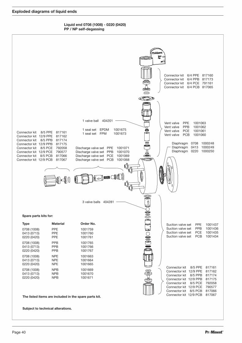
Exploded diagrams of liquid ends
Liquid end 0708 (1008) - 0220 (0420)PP / NP self-degassing
The listed items are included in the spare parts kit.
Subject to technical alterations.
Connector kit 8/5 PPE 817161Connector kit 12/9 PPE 817162Connector kit 8/5 PPB 817174Connector kit 12/9 PPB 817175Connector kit 8/5 PCE 792058Connector kit 12/9 PCE 790577Connector kit 8/5 PCB 817066Connector kit 12/9 PCB 817067
1 seal set EPDM 10016751 seal set FPM 1001673
1 valve ball 404201
3 valve balls 404281
Discharge valve set PPE 1001071Discharge valve set PPB 1001070Discharge valve set PCE 1001069Discharge valve set PCB 1001068
Connector kit 6/4 PPE 817160Connector kit 6/4 PPB 817173Connector kit 6/4 PCE 791161Connector kit 6/4 PCB 817065
Vent valve PPE 1001063Vent valve PPB 1001062Vent valve PCE 1001061Vent valve PCB 1001060
Diaphragm 0708 1000248Diaphragm 0413 1000249Diaphragm 0220 1000250
Suction valve set PPE 1001437Suction valve set PPB 1001436Suction valve set PCE 1001435Suction valve set PCB 1001434
Connector kit 8/5 PPE 817161Connector kit 12/9 PPE 817162Connector kit 8/5 PPB 817174Connector kit 12/9 PPB 817175Connector kit 8/5 PCE 792058Connector kit 12/9 PCE 790577Connector kit 8/5 PCB 817066Connector kit 12/9 PCB 817067
Spare parts kits for:
Type Material Order No.
0708 (1008) PPE 10017590413 (0713) PPE 10017600220 (0420) PPE 1001761
0708 (1008) PPB 10017650413 (0713) PPB 10017660220 (0420) PPB 1001767
0708 (1008) NPE 10016630413 (0713) NPE 10016640220 (0420) NPE 1001665
0708 (1008) NPB 10016690413 (0713) NPB 10016700220 (0420) NPB 1001671
BA_BE_021_07_08_GB2.p65 17.07.2008, 14:35 Uhr40
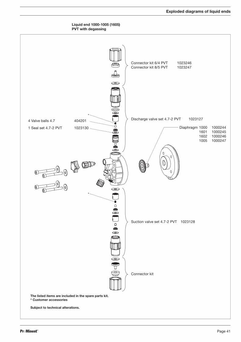
ProMinent® Page 41
Liquid end 1000-1005 (1605)PVT with degassing
The listed items are included in the spare parts kit.* Customer accessories
Subject to technical alterations.
Connector kit 6/4 PVT 1023246Connector kit 8/5 PVT 1023247
Discharge valve set 4.7-2 PVT 1023127
Suction valve set 4.7-2 PVT 1023128
Connector kit
Diaphragm 1000 1000244Membran 1601 1000245Membran 1602 1000246Membran 1005 1000247
1 Seal set 4.7-2 PVT 1023130
4 Valve balls 4.7 404201
Exploded diagrams of liquid ends
*
*
BA_BE_021_07_08_GB2.p65 17.07.2008, 14:35 Uhr41
ProMinent®Page 42
Exploded diagrams of liquid ends
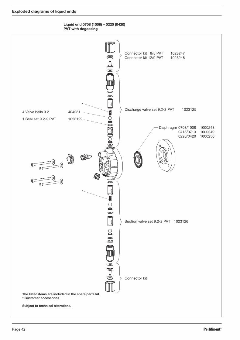
Liquid end 0708 (1008) – 0220 (0420)PVT with degassing
The listed items are included in the spare parts kit.* Customer accessories
Subject to technical alterations.
Diaphragm 0708/1008 1000248Membran 0413/0713 1000249Membran 0220/0420 1000250
Connector kit 18/5 PVT 1023247Connector kit 12/9 PVT 1023248
Discharge valve set 9.2-2 PVT 1023125
Suction valve set 9.2-2 PVT 1023126
Connector kit
1 Seal set 9.2-2 PVT 1023129
4 Valve balls 9.2 404281
*
*
BA_BE_021_07_08_GB2.p65 17.07.2008, 14:35 Uhr42
ProMinent® Page 43
Exploded diagrams of liquid ends
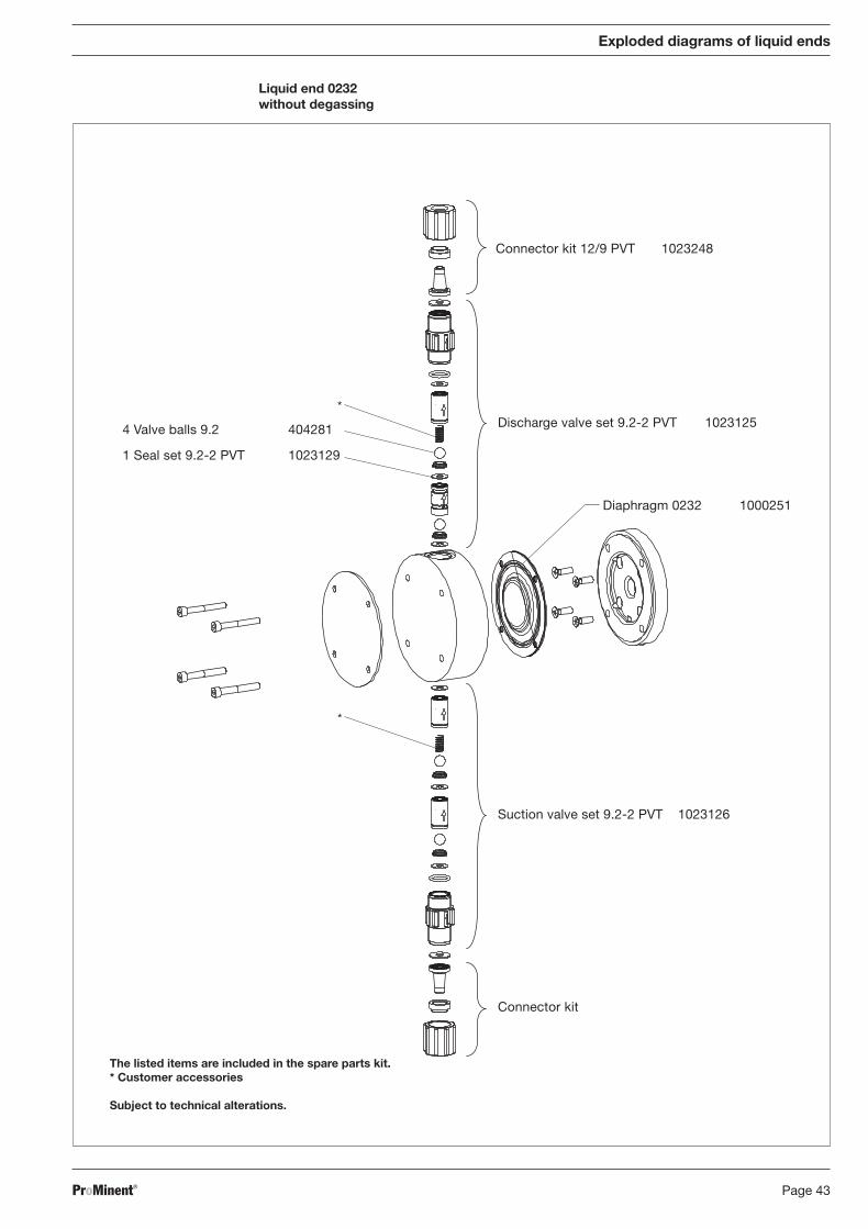
Liquid end 0232without degassing
The listed items are included in the spare parts kit.* Customer accessories
Subject to technical alterations.
1 Seal set 9.2-2 PVT 1023129
4 Valve balls 9.2 404281
Connector kit 12/9 PVT 1023248
Discharge valve set 9.2-2 PVT 1023125
Diaphragm 0232 1000251
Suction valve set 9.2-2 PVT 1023126
Connector kit
*
*
BA_BE_021_07_08_GB2.p65 17.07.2008, 14:35 Uhr43

ProMinent®Page 44
Exploded diagrams of liquid ends
Liquid end 1000 - 1005 (1605)TT
*
*
60_07-104_00_29-04_2
Connector kit 6/4 TTT 817201Connector kit 8/5 TTT 817204
Discharge valve set TTT 809406
Diaphragm 1000 1000244Diaphragm 1601 1000245Diaphragm 1602 1000246Diaphragm 1005 1000247
Suction valve set TTT 809407
Connector kit
Spare parts kits for:
Type Material Order No.
1000 TTT 10017371601 TTT 10017381602 TTT 10017391005 (1605) TTT 1001740
4 valve balls 404201
11 seals PTFE 483907
The listed items are included in the spare parts kit.* Customer accessories
Subject to technical alterations.
BA_BE_021_07_08_GB2.p65 17.07.2008, 14:35 Uhr44
ProMinent® Page 45
Exploded diagrams of liquid ends
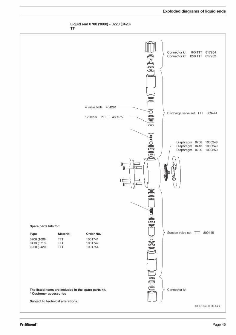
Liquid end 0708 (1008) - 0220 (0420)TT
*
*
60_07-104_00_30-04_2
Connector kit 8/5 TTT 817204Connector kit 12/9 TTT 817202
Discharge valve set TTT 809444
Diaphragm 0708 1000248Diaphragm 0413 1000249Diaphragm 0220 1000250
Suction valve set TTT 809445
Connector kit
4 valve balls 404281
12 seals PTFE 483975
Spare parts kits for:
Type Material Order No.
0708 (1008) TTT 10017410413 (0713) TTT 10017420220 (0420) TTT 1001754
The listed items are included in the spare parts kit.* Customer accessories
Subject to technical alterations.
BA_BE_021_07_08_GB2.p65 17.07.2008, 14:35 Uhr45
ProMinent®Page 46
Exploded diagrams of liquid ends
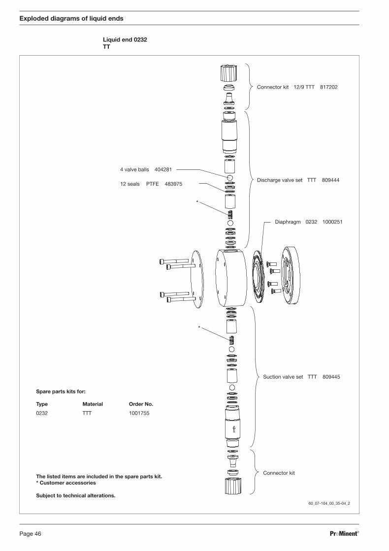
Liquid end 0232TT
*
*
60_07-104_00_35-04_2
Connector kit 12/9 TTT 817202
Discharge valve set TTT 809444
Diaphragm 0232 1000251
Suction valve set TTT 809445
Connector kit
4 valve balls 404281
12 seals PTFE 483975
Spare parts kits for:
Type Material Order No.
0232 TTT 1001755
The listed items are included in the spare parts kit.* Customer accessories
Subject to technical alterations.
BA_BE_021_07_08_GB2.p65 17.07.2008, 14:35 Uhr46

ProMinent® Page 47
Exploded diagrams of liquid ends
Liquid end 1000 - 1005 (1605)SS
*
*
60_07-104_00_25-04_2
Connector kit 6 mm SS 104233
Discharge valve set 6 mm SST 809418
Diaphragm 1000 1000244Diaphragm 1601 1000245Diaphragm 1602 1000246Diaphragm 1005 1000247
Suction valve set 6 mm SST 809419
Connector kit
4 valve balls 404201
12 seals PTFE 483907
Spare parts kits for:
Type Material Order No.
1000 SST 10017291601 SST 10017301602 SST 10017311005 (1605) SST 1001732
The listed items are included in the spare parts kit.* Customer accessories
Subject to technical alterations.
BA_BE_021_07_08_GB2.p65 17.07.2008, 14:35 Uhr47
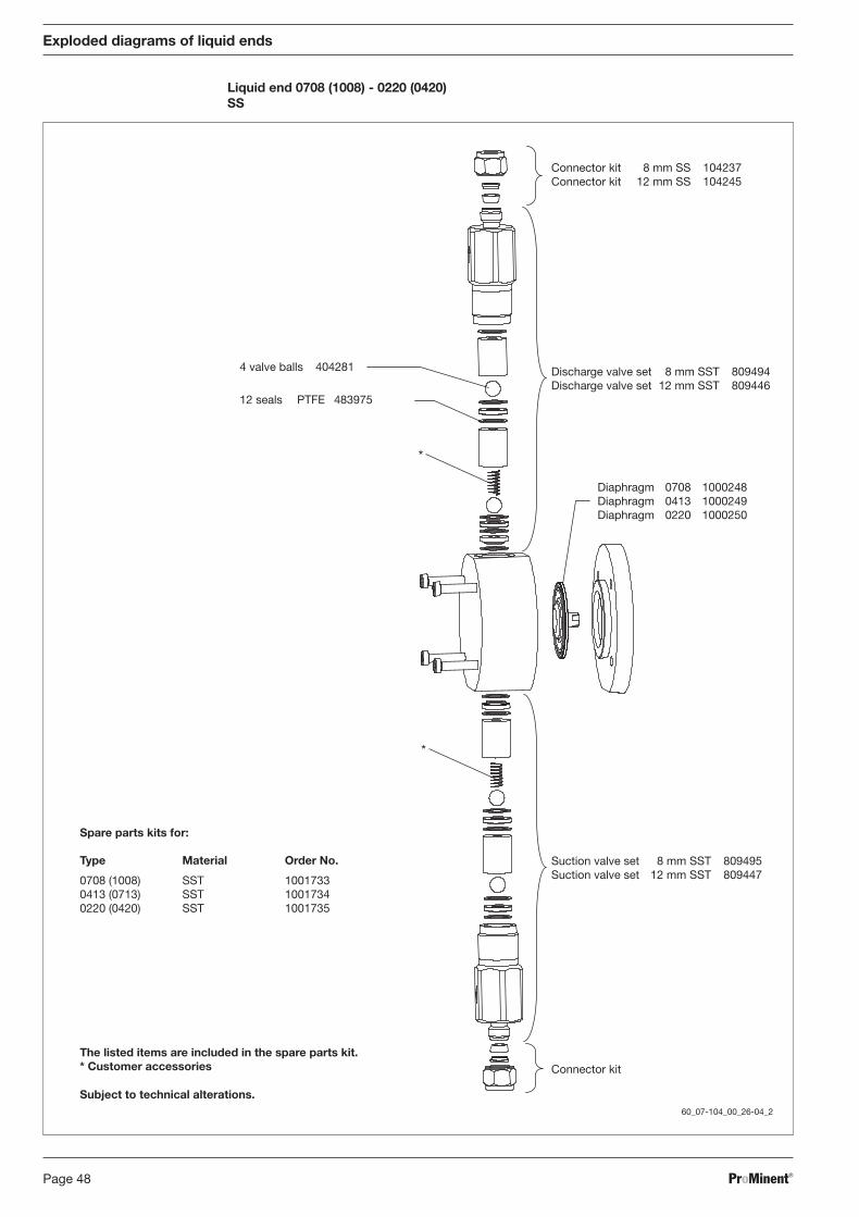
ProMinent®Page 48
Exploded diagrams of liquid ends
Liquid end 0708 (1008) - 0220 (0420)SS
*
*
60_07-104_00_26-04_2
Connector kit 8 mm SS 104237Connector kit 12 mm SS 104245
Discharge valve set 8 mm SST 809494Discharge valve set 12 mm SST 809446
Diaphragm 0708 1000248Diaphragm 0413 1000249Diaphragm 0220 1000250
Suction valve set 8 mm SST 809495Suction valve set 12 mm SST 809447
Connector kit
4 valve balls 404281
12 seals PTFE 483975
Spare parts kits for:
Type Material Order No.
0708 (1008) SST 10017330413 (0713) SST 10017340220 (0420) SST 1001735
The listed items are included in the spare parts kit.* Customer accessories
Subject to technical alterations.
BA_BE_021_07_08_GB2.p65 17.07.2008, 14:35 Uhr48
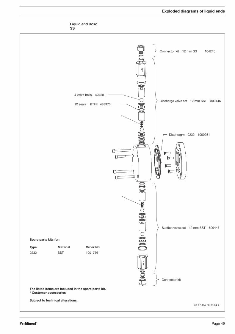
ProMinent® Page 49
Exploded diagrams of liquid ends
Liquid end 0232SS
60_07-104_00_36-04_2
*
*
The listed items are included in the spare parts kit.* Customer accessories
Subject to technical alterations.
Connector kit 12 mm SS 104245
Discharge valve set 12 mm SST 809446
Diaphragm 0232 1000251
Suction valve set 12 mm SST 809447
Connector kit
4 valve balls 404281
12 seals PTFE 483975
Spare parts kits for:
Type Material Order No.
0232 SST 1001736
BA_BE_021_07_08_GB2.p65 17.07.2008, 14:35 Uhr49

ProMinent®Page 50
BA_BE_021_07_08_GB2.p65 17.07.2008, 14:35 Uhr50

ProMinent® Page 51
BA_BE_021_07_08_GB2.p65 17.07.2008, 14:35 Uhr51

ProMinent Argentina S.A. (Argentina)Tel.: +54 11 [email protected]
ProMinent Fluid Controls Pty. Ltd. (Australia)Tel.: +61 2 [email protected]
ProMinent Dosiertechnik Ges. mbH (Austria)Tel.: +43 7448 [email protected]
ProMinent Fluid Controls (Bangladesh) Ltd.(Bangladesh)Tel.: +8802 [email protected].
ProMinent Belgium S.A., N.V. (Belgium)Tel.: +32 2 [email protected]
ProMinent Brasil Ltda. (Brazil)Tel.: +55 11 [email protected]
ProMinent Fluid Controls BG (Bulgaria)Tel.: +359 2 [email protected]
ProMinent Fluid Controls Ltd. (Canada)Tel.: +1 519 [email protected]
ProMinent Fluid Controls China Co. Ltd.(P.R. of China)Tel.: +86 411 [email protected]
ProMinent Bermat S.A. (Chile)Tel.: +56 2 3354 [email protected]
ProMinent Dosiertechnik CS s.r.o.(Czech Republ.)Tel.: +420 585 [email protected]
ProMinent Finland OY (Finland)Tel.: +35 89 [email protected]
ProMinent France S.A. (France)Tel.: +33 3 [email protected]
ProMinent ProMaqua GmbH (Germany)Tel.: +49 6221 [email protected]
ProMinent Fluid Controls (UK) Ltd. (Great Britain)Tel.: +44 1530 [email protected]
Tochtergesellschaften / Subsidiaries
Vertretungen weltweit / Distributors WorldwideAngola · Bahrain · Bolivia · Botswana · Cameroon · Colombia · Costa Rica · Croatia · Cuba · Cyprus · Denmark · Ecuador · Egypt · El Salvador · Ethiopia · Ghana ·Guatemala · Hong Kong · Indonesia · Iran · Ireland · Island · Israel · Jordan · Kenya · Kuwait · Macedonien · Malta · Mauritius · Montenegro · Mozambique ·Namibia · New Zealand · Nigeria · Norway · Oman · Pakistan · Panama · Paraguay · Peru · Philippines · Qatar · Saudi Arabia · Serbia · Slovenia · Sudan · Syria ·Tanzania · Tunesia · Turkey · Turkmenistan · UAE · Uganda · Uruguay · Venezuela · Vietnam · White Russia · Zambia · Zimbabwe
Anschriftennachweise erhalten Sie durch: / Addresses of distributors are available from: ProMinent Dosiertechnik GmbH, Germany
Die ProMinent Firmengruppe / The ProMinent Group
ProMinent Hellas Ltd. (Greece)Tel.: +30 210 5134621 / [email protected]
ProMinent Magyarország Kft. (Hungary)Tel.: +36 96 [email protected]
Heidelberg ProMinent Fluid Controls India Pvt. Ltd.(India)Tel.: +91 80 [email protected]
ProMinent Fluid Controls Ltd. (Ireland)Tel.: +353 71 [email protected]
ProMinent Italiana S.R.L. (Italy)Tel.: +39 0471 [email protected]
ProMinent Japan Ltd. (Japan)Tel.: +81 35812 [email protected]
ProMinent Korea Co. Ltd. (Republic of Korea)Tel.: +82 31 [email protected]
ProMinent Office Kazakhstan (Kazakhstan)Tel.: +7 3272 [email protected]
ProMinent Office Kaunas (Lithuania)Tel.: +370 37 [email protected]
ProMinent Fluid Controls (M) Sdn. Bhd.(Malaysia)Tel: +603-806 825 [email protected]
ProMinent Fluid Controls Ltd. (Malta)Tel.: +356 [email protected]
ProMinent Fluid Controls de México, S.A. de C.V.(Mexico)Tel.: +52 (442) 2189920 / [email protected]
ProMinent Verder B.V. (Netherlands)Tel.: +31 30 [email protected]
ProMinent Dozotechnika Sp. z o.o. (Poland)Tel.: +48 71 [email protected]
ProMinent Portugal Controlo de Fluídos, Lda.(Portugal)Tel.: +35 121 [email protected]
05/08
ProMinent Verder s.r.l. (Romania)Tel.: +40 269 [email protected]
ProMinent Dositechnika OOO (Russia)Tel.: +7 095 [email protected]
Proshield Ltd. (Scotland)Tel.: +44 1698 [email protected]
ProMinent Fluid Controls (Far East) Pte. Ltd.(Singapore)Tel.: +65 [email protected]
ProMinent Slovensko s.r.o. (Slovak. Republ.)Tel.: +421 2 [email protected]
ProMinent Fluid Controls Pty. Ltd. (South Africa)Tel.: +27 11 [email protected]
ProMinent Gugal S.A. (Spain)Tel.: +34 972 287011/[email protected]
ProMinent Doserteknik AB (Sweden)Tel.: +46 31 [email protected]
Tomal AB (Sweden)Tel.: +46 (0) [email protected]
ProMinent Dosiertechnik AG (Switzerland)Tel.: +41 44 [email protected]
ProMinent Fluid Controls (Taiwan) Ltd. (Taiwan)Tel.: +886 7 [email protected]
ProMinent Fluid Controls (Thailand) Co. Ltd.(Thailand)Tel.: +66 2 [email protected]
ProMinent Office Kiev (Ukraine)Tel.: +380 44576 [email protected]
ProMinent Fluid Controls, Inc. (USA)Tel.: +1 412 [email protected]
ProMinent Juffali FZC (UAE)Tel.: +97 1655 [email protected]
Stammhaus / Head officeProMinent Dosiertechnik GmbH · Im Schuhmachergewann 5-11 · 69123 Heidelberg · [email protected] · www.prominent.com · Tel.: +49 6221 842-0 · Fax: +49 6221 842-617
Anschr_D_GB_05_08_sw.p65 07.05.2008, 14:49 Uhr1