Operating Instructions - Kurt J. Lesker Company | Home …€¦ · · 2012-10-24Up-to-date...
36
Translation of the original instructions Operating Instructions EN PD 0042 BEN/D (1108) Hena 200/300 Rotary Vane Pump
Transcript of Operating Instructions - Kurt J. Lesker Company | Home …€¦ · · 2012-10-24Up-to-date...
Tra
nsl
atio
n of
the
orig
inal
inst
ruct
ions
PD
004
2 B
EN
/D (
1108
)
Hena 200/300Rotary Vane Pump
Operating Instructions
EN

Table of contents
Table of contents
1 About this manual . . . . . . . . . . . . . . . . . . . . . . . . . . . . . . . . . . . . . . . . . . . . . . . 3
1.1 Validity. . . . . . . . . . . . . . . . . . . . . . . . . . . . . . . . . . . . . . . . . . . . . . . . . . . . . 3
1.2 Conventions . . . . . . . . . . . . . . . . . . . . . . . . . . . . . . . . . . . . . . . . . . . . . . . . 3
2 Safety . . . . . . . . . . . . . . . . . . . . . . . . . . . . . . . . . . . . . . . . . . . . . . . . . . . . . . . . . 5
2.1 Safety precautions . . . . . . . . . . . . . . . . . . . . . . . . . . . . . . . . . . . . . . . . . . . 5
2.2 Protective equipment . . . . . . . . . . . . . . . . . . . . . . . . . . . . . . . . . . . . . . . . . 6
2.3 Proper use . . . . . . . . . . . . . . . . . . . . . . . . . . . . . . . . . . . . . . . . . . . . . . . . . 6
2.4 Improper use. . . . . . . . . . . . . . . . . . . . . . . . . . . . . . . . . . . . . . . . . . . . . . . . 6
3 Transport and storage. . . . . . . . . . . . . . . . . . . . . . . . . . . . . . . . . . . . . . . . . . . . 7
3.1 Transport. . . . . . . . . . . . . . . . . . . . . . . . . . . . . . . . . . . . . . . . . . . . . . . . . . . 7
3.2 Storage . . . . . . . . . . . . . . . . . . . . . . . . . . . . . . . . . . . . . . . . . . . . . . . . . . . . 7
4 Product description. . . . . . . . . . . . . . . . . . . . . . . . . . . . . . . . . . . . . . . . . . . . . . 8
4.1 Product identification. . . . . . . . . . . . . . . . . . . . . . . . . . . . . . . . . . . . . . . . . . 8
4.2 Function . . . . . . . . . . . . . . . . . . . . . . . . . . . . . . . . . . . . . . . . . . . . . . . . . . . 9
4.3 Range of application . . . . . . . . . . . . . . . . . . . . . . . . . . . . . . . . . . . . . . . . . . 9
5 Installation . . . . . . . . . . . . . . . . . . . . . . . . . . . . . . . . . . . . . . . . . . . . . . . . . . . . 10
5.1 Setting up the pump . . . . . . . . . . . . . . . . . . . . . . . . . . . . . . . . . . . . . . . . . 10
5.2 Connecting the vacuum side. . . . . . . . . . . . . . . . . . . . . . . . . . . . . . . . . . . .11
5.3 Connecting the exhaust side. . . . . . . . . . . . . . . . . . . . . . . . . . . . . . . . . . . .11
5.4 Connecting to the mains power supply . . . . . . . . . . . . . . . . . . . . . . . . . . . 12
5.5 Filling up the operating fluid . . . . . . . . . . . . . . . . . . . . . . . . . . . . . . . . . . . 14
5.6 Operating fluid temperature monitoring (option) . . . . . . . . . . . . . . . . . . . . 14
5.7 Operating fluid level monitoring (option) . . . . . . . . . . . . . . . . . . . . . . . . . . 15
5.8 Connecting the heat exchanger (option). . . . . . . . . . . . . . . . . . . . . . . . . . 15
6 Operation . . . . . . . . . . . . . . . . . . . . . . . . . . . . . . . . . . . . . . . . . . . . . . . . . . . . . 17
6.1 Before switching on. . . . . . . . . . . . . . . . . . . . . . . . . . . . . . . . . . . . . . . . . . 17
6.2 Switching on the pump . . . . . . . . . . . . . . . . . . . . . . . . . . . . . . . . . . . . . . . 17
6.3 Pumping condensable vapours. . . . . . . . . . . . . . . . . . . . . . . . . . . . . . . . . 18
6.4 Switching off the pump . . . . . . . . . . . . . . . . . . . . . . . . . . . . . . . . . . . . . . . 19
7 Maintenance. . . . . . . . . . . . . . . . . . . . . . . . . . . . . . . . . . . . . . . . . . . . . . . . . . . 20
7.1 Precautions . . . . . . . . . . . . . . . . . . . . . . . . . . . . . . . . . . . . . . . . . . . . . . . . 20
7.2 Changing the operating fluid . . . . . . . . . . . . . . . . . . . . . . . . . . . . . . . . . . . 21
7.3 Changing the exhaust filter in the operating fluid separator . . . . . . . . . . . 23
7.4 Cleaning the float valve. . . . . . . . . . . . . . . . . . . . . . . . . . . . . . . . . . . . . . . 25
7.5 Changing the intake filter . . . . . . . . . . . . . . . . . . . . . . . . . . . . . . . . . . . . . 26
7.6 Changing the gas ballast filter. . . . . . . . . . . . . . . . . . . . . . . . . . . . . . . . . . 26
7.7 Cleaning the fan covers and radiator . . . . . . . . . . . . . . . . . . . . . . . . . . . . 26
8 Decommissioning . . . . . . . . . . . . . . . . . . . . . . . . . . . . . . . . . . . . . . . . . . . . . . 27
8.1 Shutting down for longer periods . . . . . . . . . . . . . . . . . . . . . . . . . . . . . . . 27
8.2 Re-starting . . . . . . . . . . . . . . . . . . . . . . . . . . . . . . . . . . . . . . . . . . . . . . . . 27
8.3 Disposal . . . . . . . . . . . . . . . . . . . . . . . . . . . . . . . . . . . . . . . . . . . . . . . . . . 27
9 Malfunctions . . . . . . . . . . . . . . . . . . . . . . . . . . . . . . . . . . . . . . . . . . . . . . . . . . 27
9.1 Rectifying malfunctions . . . . . . . . . . . . . . . . . . . . . . . . . . . . . . . . . . . . . . . 28
10 Service . . . . . . . . . . . . . . . . . . . . . . . . . . . . . . . . . . . . . . . . . . . . . . . . . . . . . . . 29
11 Spare parts . . . . . . . . . . . . . . . . . . . . . . . . . . . . . . . . . . . . . . . . . . . . . . . . . . . . 30
11.1 Spare parts packages . . . . . . . . . . . . . . . . . . . . . . . . . . . . . . . . . . . . . . . . 31
12 Accessories . . . . . . . . . . . . . . . . . . . . . . . . . . . . . . . . . . . . . . . . . . . . . . . . . . . 31
13 Technical data . . . . . . . . . . . . . . . . . . . . . . . . . . . . . . . . . . . . . . . . . . . . . . . . . 32
Declaration of conformity . . . . . . . . . . . . . . . . . . . . . . . . . . . . . . . . . . . . . . . . 35
2

About this manual
1 About this manual
1.1 ValidityThis operating manual is for customers of Pfeiffer Vacuum. It describes the functioning of the designated product and provides the most important information for safe use of the unit. The description follows applicable EU guidelines. All information provided in this op-erating manual refer to the current state of the product's development. The documenta-tion remains valid as long as the customer does not make any changes to the product.
Up-to-date operating instructions can also be downloaded from www.pfeiffer-vacu-um.com.
Applicable docu-ments
*also available via www.pfeiffer-vacuum.com
1.2 Conventions
Safety instructions The safety instructions in Pfeiffer Vacuum operating manuals are the result of risk eval-uations and hazard analyses and are oriented on international certification standards as specified by UL, CSA, ANSI Z-535, SEMI S1, ISO 3864 and DIN 4844. In this document, the following hazard levels and information are considered:
Hena 200/300 Operating instructionsDeclaration of Conformity Part of this document
Operating instructions for accessories (order-specifically) see section "accessories"*
DANGER
Immediate danger
Death or very severe injuries can occur.
WARNING
Possible danger
Injuries or severe property damages can occur.
CAUTION
Possible danger
Injuries or property damages can occur.
NOTE
Command or note
Command to perform an action or information about properties, the disregarding of which may result in damage to the product.
3

About this manual
Pictograph defini-tions
Instructions in the text
Work instruction: here you have to do something.
Symbols used The following symbols are used consistently throughout in all illustrations:
Vacuum flange
Exhaust flange
Gas ballast valve
Power connection
Prohibition of an action or activity in connection with a source of danger, the disregarding of which may result in serious ac-cidents.
Warning of a displayed source of danger in connection with operation of the unit or equipment.
Command to perform an action or task associated with a source of danger, the disregarding of which may result in se-rious accidents.
V
G
4
Safety
2 Safety
2.1 Safety precautions
● Do not expose any body parts to the vacuum.
● Observe the safety and accident prevention regulations.
● Check regularly that all safety precautions are being complied with.
● Do not carry out any unauthorised modifications or conversions to the pumps.
● Depending on the operating and ambient conditions, the surface temperature of the pumps may rise above 70 °C. Use suitable finger guards if necessary.
● When returning the pumps to us please note the instructions in the Service section.
NOTE
Duty to inform
Each person involved in the installation, operation or maintenance of the vacuum pump must read and observe the safety-related parts of these operating instructions.
The operator is obligated to make operating personnel aware of dangers originating from the vacuum pump, the pumped medium and the entire system.
NOTE
Installation and operation of accessories
Pfeiffer Vacuum pumps can be equipped with a series of adapted accessories. The in-stallation, operation and maintenance of connected devices are described in detail in the operating instructions of the individual components.
For information on order numbers of components, see "Accessories".Use original accessory parts only.
5

Safety
2.2 Protective equipmentDetermined situations concerning the handling of vacuum pumps require wearing of per-sonal protective equipment. The owner, respectively the employer are obligated to pro-vide adequate equipment to any operating persons.
2.3 Proper use
● The vacuum pump may only be used to generate a vacuum.
● Installation, operating and maintenance regulations must be complied with.
● Other accessories, than those described in this manual, must not be used without the agreement of Pfeiffer Vacuum.
2.4 Improper useImproper use will cause all claims for liability and warranties to be forfeited. Improper use is deemed to be all use for purposes deviating from those mentioned above, especially:
● Pumping of corrosive gases.
● Pumping of explosive media.
● Operation in potentially explosive areas.
● Pumping of gases containing impurities such as particles, dusts and condensate; note the vapour compatibility levels of the pump.
● Pumping of substances that tend to sublime.
● Use of the vacuum pump to generate pressure.
● Pumping of liquids.
DANGER
Danger to health by hazardous substances during maintenance or installation
Depending on the process vacuum pumps, components or operating fluids can be con-taminated by toxic, reactive or radioactive substances.
Wear adequate protective equipment during maintenance and repairs or in case of reinstallation.
CAUTION
Risk of injury through hot surfaces
Vacuum pumps can become hot during operation.
Allow the pump to cool before maintenance and repairs. If necessary wear protective gloves according to directive EN 420.
WARNING
Increased noise emission!
Increased noise emission can occur within a limited area surrounding the vacuum pump.
Provide noise protection orwear hearing protection.
NOTE
CE conformity
The manufacturer's declaration of conformity becomes invalid if the operator modifies the original product or installs additional components.
Following installation into a plant and before commissioning, the operator must check the entire system for compliance with the valid EU directives and reassess it accord-ingly.
6

Transport and storage
● The use of operating fluids not specified by Pfeiffer Vacuum.
● Connection to pumps or units which are not suitable for this purpose according to their operating instructions.
● Connection to units which have exposed voltage-carrying parts.
● The operation of the devices in potentially radioactive areas.
3 Transport and storage
3.1 Transport
Look for transportation damage when receiving the pump.
Use only a forklift to transport pump packed on pallet.
Unpack pump and undo screws on transport container.
Reuse the transport container. Vacuum pumps should be transported or shipped in the original packing only.
Transport without packaging
Remove the locking cap from the vacuum and exhaust flange immediately before con-necting!
Use only the eye bolt on the top side of the pump to lift the pump.
To lift the pump without motor and if accessories are mounted, fit another strap at a suitable position.
3.2 StorageCheck that all the openings on the pump are securely closed.
Store the pump in a cool, dry place; preferably at temperatures between -10 °C and +40 °C.– For a longer period of storage, seal the pump in a PE bag with drying agents en-
closed.– For a period of storage longer than two years, it is recommended to change the op-
erating fluid before using the pump.
WARNING
Danger from falling and swinging loads!
When lifting the pump there is a danger of falling parts.
Make sure that there are no persons under the suspended load.Close off and supervise the area under the pump.
CAUTION
Operating fluid overflows into the pump system if the pump is tilted!
Vane fractures when pump starts up.
Only transport pump without operating fluid.
7

Product description
4 Product description
4.1 Product identificationTo correctly identify the product when communicating with Pfeiffer Vacuum, always have the information from the rating plate available and use it:
● Pump model and model number
● Serial number
● Type and amount of operating fluid
● Date of manufacture
Please find the voltage range and motor-related data on the separately attached motor rating plate.
Scope of delivery ● Pump with drive unit
● Locking cap for vacuum flange
● Operating fluid P3 (for standard pump)
● Operating instructions
Pump typesPump type Pump versionsHena 200 Standard version of pump
● Vacuum and exhaust flange: DN 100 ISO-K● Operating fluid return unit via float valve● Pressure gauge (manometer) for pressure control in the operating fluid separator● Three-phase motors with 3 PTC motor protection● Gas ballast valve
Hena 300 Standard version of pump● Vacuum and exhaust flange: DN 100 ISO-K● Operating fluid return unit via float valve● Pressure gauge (manometer) for pressure control in the operating fluid separator● Three-phase motors with 3 PTC motor protection● Gas ballast valve
8
Product description
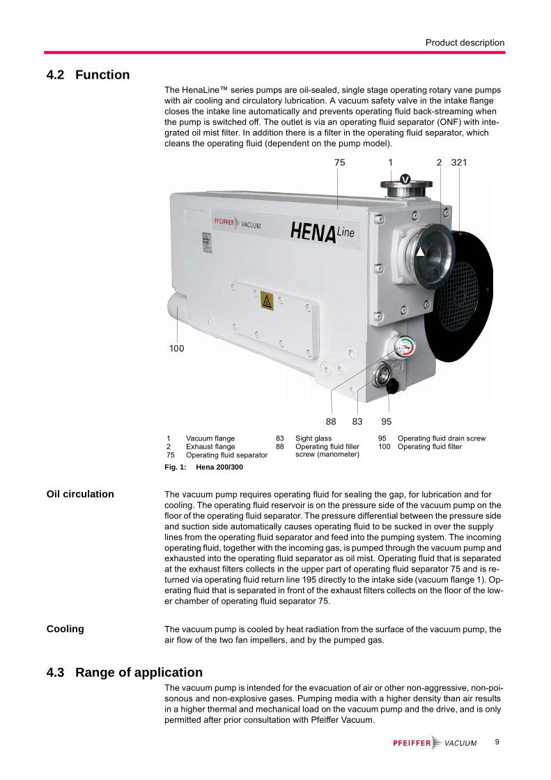
4.2 FunctionThe HenaLine™ series pumps are oil-sealed, single stage operating rotary vane pumps with air cooling and circulatory lubrication. A vacuum safety valve in the intake flange closes the intake line automatically and prevents operating fluid back-streaming when the pump is switched off. The outlet is via an operating fluid separator (ONF) with inte-grated oil mist filter. In addition there is a filter in the operating fluid separator, which cleans the operating fluid (dependent on the pump model).
Fig. 1: Hena 200/300
Oil circulation The vacuum pump requires operating fluid for sealing the gap, for lubrication and for cooling. The operating fluid reservoir is on the pressure side of the vacuum pump on the floor of the operating fluid separator. The pressure differential between the pressure side and suction side automatically causes operating fluid to be sucked in over the supply lines from the operating fluid separator and feed into the pumping system. The incoming operating fluid, together with the incoming gas, is pumped through the vacuum pump and exhausted into the operating fluid separator as oil mist. Operating fluid that is separated at the exhaust filters collects in the upper part of operating fluid separator 75 and is re-turned via operating fluid return line 195 directly to the intake side (vacuum flange 1). Op-erating fluid that is separated in front of the exhaust filters collects on the floor of the low-er chamber of operating fluid separator 75.
Cooling The vacuum pump is cooled by heat radiation from the surface of the vacuum pump, the air flow of the two fan impellers, and by the pumped gas.
4.3 Range of applicationThe vacuum pump is intended for the evacuation of air or other non-aggressive, non-poi-sonous and non-explosive gases. Pumping media with a higher density than air results in a higher thermal and mechanical load on the vacuum pump and the drive, and is only permitted after prior consultation with Pfeiffer Vacuum.
1 Vacuum flange2 Exhaust flange75 Operating fluid separator
83 Sight glass88 Operating fluid filler
screw (manometer)
95 Operating fluid drain screw100 Operating fluid filter
75 1 2 321
88 83 95
100
9
Installation
5 Installation
5.1 Setting up the pump
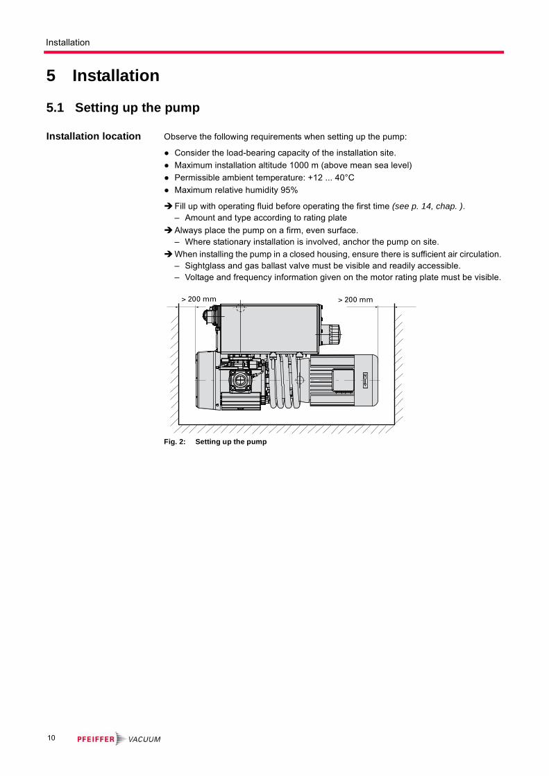
Installation location Observe the following requirements when setting up the pump:
● Consider the load-bearing capacity of the installation site.
● Maximum installation altitude 1000 m (above mean sea level)
● Permissible ambient temperature: +12 ... 40°C
● Maximum relative humidity 95%
Fill up with operating fluid before operating the first time (see p. 14, chap. ).– Amount and type according to rating plate
Always place the pump on a firm, even surface.– Where stationary installation is involved, anchor the pump on site.
When installing the pump in a closed housing, ensure there is sufficient air circulation.– Sightglass and gas ballast valve must be visible and readily accessible.– Voltage and frequency information given on the motor rating plate must be visible.
Fig. 2: Setting up the pump
> 200 mm> 200 mm
10

Installation
5.2 Connecting the vacuum sideRemove locking cap from the vacuum flange and insert centering ring.
The connection between the pump and the recipient should be kept as short as pos-sible.– Depending on the pump type, use metallic hoses or PVC hoses with flange con-
nections.– Separators, filters etc. may be installed upstream to protect the pump (see acces-
sories). However, please observe the loss of pumping capacity due to the conduc-tivity of the accessories.
5.3 Connecting the exhaust side
Choose the cross-section of the exhaust line to be at least the size of the nominal con-nection diameter of the vacuum pump's exhaust connection.
Piping to the pump must be suspended or supported.– Physical forces from the piping system must not be allowed to act on vacuum
pumps.
Lay piping from the pump sloping downward so that no condensate can flow back into the pump; otherwise fit a condensate separator.– If an air trap is created in the system, then a device for draining condensation water
must be provided at the lowest point.
CAUTION
High pressure in the exhaust line!
Danger of damage to the seals and danger of the pump bursting.
Install the line without shut-off valves on the exhaust side. If there is danger of a build-up of excess pressure (> 1500 mbar abs.) in the lines,
observe all official accident prevention safety regulations.
WARNING
Emission of toxic substances from the exhaust!
Danger of poisoning from emitted gases or vapours, which can be detrimental to health and/or can pollute the environment, depending on the particular application.
Comply with the applicable regulations when working with toxic substances.Only officially approved filter systems may be used to separate and remove these
substances.
11

Installation
5.4 Connecting to the mains power supplyDepending on the pump type, different motor versions or mains voltages are possible:
● Three phase motor (with 3 PTC) without switch and mains cable.
Three-phase motor Inspection of the direction of rotation
With pumps with three-phase motors is it necessary to check the direction of rotation!
Remove the locking cap from the exhaust flange (if existing).
Switch the pump on briefly (from 2 to 3 sec.).– Rotation must be in a clockwise direction in view of the shaft end of the motor (see
the arrow on the fan cover).
If the direction of rotation is incorrect: Swap two phase contacts at the connecting ca-ble.
Fill up the operating fluid.
Motor protection
Pump motors equipped with PTC temperature sensors (3PTC) in the stator windings can be connected to a PTC resistor tripping device for protection against overload. Other ap-proved motor temperature monitoring can be used also by the operator.
Tripping devices store the shutdown event and need to be manually switched back on again via the integrated RESET button or via the external RESET S3. Mains-ON is de-tected as an automatic RESET.
DANGER
Voltage-bearing elements
Danger to life from electric shock.
The electrical connection can be carried out only by trained and authorised electri-cians.
Disconnect the power supply and secure it against being switched back on.Ensure the system is adequately earthed.
CAUTION
Excess voltage!
Danger of destroying the motor.
Power connections must comply with local regulations. Voltage and frequency infor-mation given on the motor rating plate must correspond to the mains voltage and fre-quency values.
To protect the motor and supply cable in case of malfunction, mains fuse protection must be implemented.
WARNING
Danger of injury from moving parts!
After power failure or motor shutdown due to overheating, the motor may restart auto-matically.
Secure the motor so that it cannot be switched on while any work is being performed on the pump.
If necessary, dismantle the pump from the installation for inspection.
CAUTION
Operating fluids may leak out!
If the direction of rotation is incorrect, there is a danger that operating fluids may leak at the vacuum flange.
Always check the direction of rotation before filling in operating fluid.
12

Installation
Set up the connections so that the directional rotation indicated on the pump is main-tained, regardless of the representations in the current flow diagram.
Fig. 3: Connection example for a three-phase AC motor with PTC resistor tripping device
The three phase current motor circuit
Delta Connection
The three coils are connected in series with the connection point connected to the mains. The voltage of each coil is the same as the mains voltage whereas the mains current is the cube root of the coil current. Delta connections are denoted by the symbol Δ. The voltage between the mains supply lines is called mains voltage. The mains current is the current which flows in the supply lines.
Fig. 4: Motor coil and connecting plate of Delta Connection (for low voltage)
Star Connection
The ends of the three coils are connected at the star center. The terminal voltage is the cube root of the coil voltage; the mains and the coil current are the same. Star connec-tions are denoted by the symbol Y.
Fig. 5: Motor coil and connecting plate of Star Connection (for high voltage)
US Control voltageS1 OFF buttonS2 ON buttonS3 RESET button, externalK1 ContactorF1 ... F4 FusesT1... T3 PTC resistor sensorH1 Tripping indicatorM Motor, 3-phase
1) Only for devices with two relay outputs
2) Only for MSR type3) Only for order no.:
P 4768 051 FQ
N
L1
M3
L2L3
F1 - F3
K1
10 11
AC 220 ... 240 VUs
F4U V W
S1
S2k1
K1
H1S3
2)
A1 A2 T1 T2 Y2Y1 24 21 22 14 12112) 2) 1) 1) 1)
T1...T3
3)
NOTE
Do not start with star/delta connection.
Always start motor directly.
W2 U1
L1
V2 V1
W1 U2
L3 L2
W2 U2 V2
U1 V1 W1
L1 L2 L3
W2
U1
L1
V2V1
W1
U2
L3 L2
W2 U2 V2
U1 V1 W1
L1 L2 L3
13

Installation
5.5 Filling up the operating fluidThe type and amount of operating fluid should be visible on the pump's rating plate for every rotary vane pump.
The delivery consignment for the standard pump contains sufficient operating fluid for one filling. The use of other operating fluids requires prior authorisation from Pfeiffer Vac-uum.
Permissible operating fluid
● P3 (standard operating fluid)
● Operating fluid for special applications on request
Filling up the operat-ing fluid
Unscrew operating fluid filler screw 88.
Fill up with operating fluid to the middle of the sight glass.– Filling quantity approx. 6.5 l of operating fluid.
Fig. 6: Filling up the operating fluid
Screw in operating fluid filler screw 88.
Close intake port valve (if present) or cover intake flange with a rubber mat.
Start pump and run it for max. 5 minutes.
Switch off pump and wait until the operating fluid has collected in the separator box.
Check fill level: The correct fill level is between the markings on the sight glass.– If the fill level drops below the "Min" marking, add operating fluid.
Open intake port valve.
5.6 Operating fluid temperature monitoring (option)A temperature switch 488, which is installed at the operating fluid separator (oil sump) is used for monitoring the operating fluid temperature.
Electrical connection of the temperature switch 488 must be carried out, so that an alarm is released and the pump is switched off, if the operating fluid temperature exceeds 100°C. The temperature switch is preset ex works.
NOTE
Use approved operating fluids only!
The use of operating fluids that have not been approved by Pfeiffer Vacuum shall result in a limited warranty. In such cases, it is not possible to guarantee that product-specific performance data will be achieved.
Prior consultation is required before using other application-specific operating fluids.
83 Sight glass88 Operating fluid filler screw
(manometer)95 Operating fluid drain screw
88
83
95
Max.
Min.
14

Installation
-
5.7 Operating fluid level monitoring (option)A level switch 4, which is installed at the operating fluid separator (oil sump) is used for monitoring the operating fluid level.
Fig. 7: Operating fluid temperature and level monitoring
5.8 Connecting the heat exchanger (option)
With applications with unfavorable environmental conditions additionally an oil/water heat exchanger can be used. The installation can take place only in the work and is later not possible.
A cooling water regulator valve 10.7 controls by means of a temperature sensor the op-erating fluid of the pump and controls the cooling water flow. Depending on the operating conditions the cooling water flow can be adjusted between 0 (maximum flow) and posi-tion 5 (minimum flow).
A solenoid valve controls the cooling water inlet and stops the flow during operating in-terrupt of the pump.
Additionally the cooling water pressure can be monitored with a pressure switch 10.4.
95 Operating fluid drain screw
488 Port for operating fluid temperature switch
496 Port for operating fluid level switch
M Mounting portT Thermometer port for
cooling water
488 T 95
M
496
142
ϑ >
123
NOTE
Damage to the pump rotor
For applications with short evacuating cycles or increased ambient temperature the ro-tor can get blocked after switching off and restarting the motor, because of different rates at which the pump housing and the rotor cool down.
Switch off water cooling supply as well as a separately driven fan immediately when switching off the pump.
10.410.510.610.2
10 10.7 10.3 10.1
1 2 3
15

Installation
Requirements for the cooling water
The cooling water must be filtered in all cases. This keeps dirt deposits and organic sus-pended particles that could accelerate pitting out of the cooling circuit. Complying with the following requirements for cooling water will prevent corrosion damage:
Connecting the cool-ing water
Connect the cooling water lines:– Cooling water inlet (10.1).– Cooling water outlet (10.2); must be pressure-free.
Open the cooling water feed.
Open the venting screw 10.5 and fill the cooling system until cooling water comes out of the outlet.
Close venting screw 10.5.
Connect cooling water line at the outlet.
Stop cooling water supply.
10 Heat exchanger (water/oil)10.1 Cooling water inlet10.2 Cooling water outlet
10.3 Filter10.4 Pressure switch10.5 Ball valve (bypass)
10.6 Solenoid valve10.7 Cooling water regulator
valve
Requirements for the cooling waterWater filtered, mechanically pure, optically clear, no turbidity, no sediments, chemically neutral
Min. oxygen content 4 mg/kg
Max. chloride content 100 mg/kg
Max. carbonate hardness for the water temperatures
15 ... 25 °C
30 ... 40 °C
60 ... 80 °C
10 ° dH
6° dH
3° dH
Max. potassium permanganate usage
pH value
10 mg/kg
7 ... 9
Aggressive carbon dioxide and ammonia must not be detectable
Max. electrical conductivity 500 μS/cm
Max. impurity particle size 25 μm
Permitted inlet overpressure range; if the pressure is higher a pressure reducer valve must be integrated
2 ... 10 bar
Required pressure differential between inlet and outlet > 0.3 bar
Permitted cooling water temperature range 15 ... 40°C
16
Operation
6 Operation
6.1 Before switching onCheck the operating fluid level in the sightglass.
Compare the voltage and frequency information on the rating plate with the mains volt-age and frequency values.
Check that the exhaust connection allows free flow (max. permissible pressure 1.5 bar absolute).– Activate the shut-off valves in such a way that they open before or at the same time
as the pump is started.
Protect the pump sufficiently from taking in contaminants by means of suitable precau-tions (e.g. dust filters); if necessary, check operating fluid regularly or replace at short-er intervals.
Open cooling water supply and check the flow; adjust if necessary.
6.2 Switching on the pumpThe pump can be switched on in any pressure range between atmospheric and
ultimate pressure.
No special precautions are necessary when pumping dry gases. In order to attain the lowest possible ultimate pressures, the gas ballast valve should be closed.
Switch on the pump with the vacuum flange closed and allow to warm up for 30 min-utes.
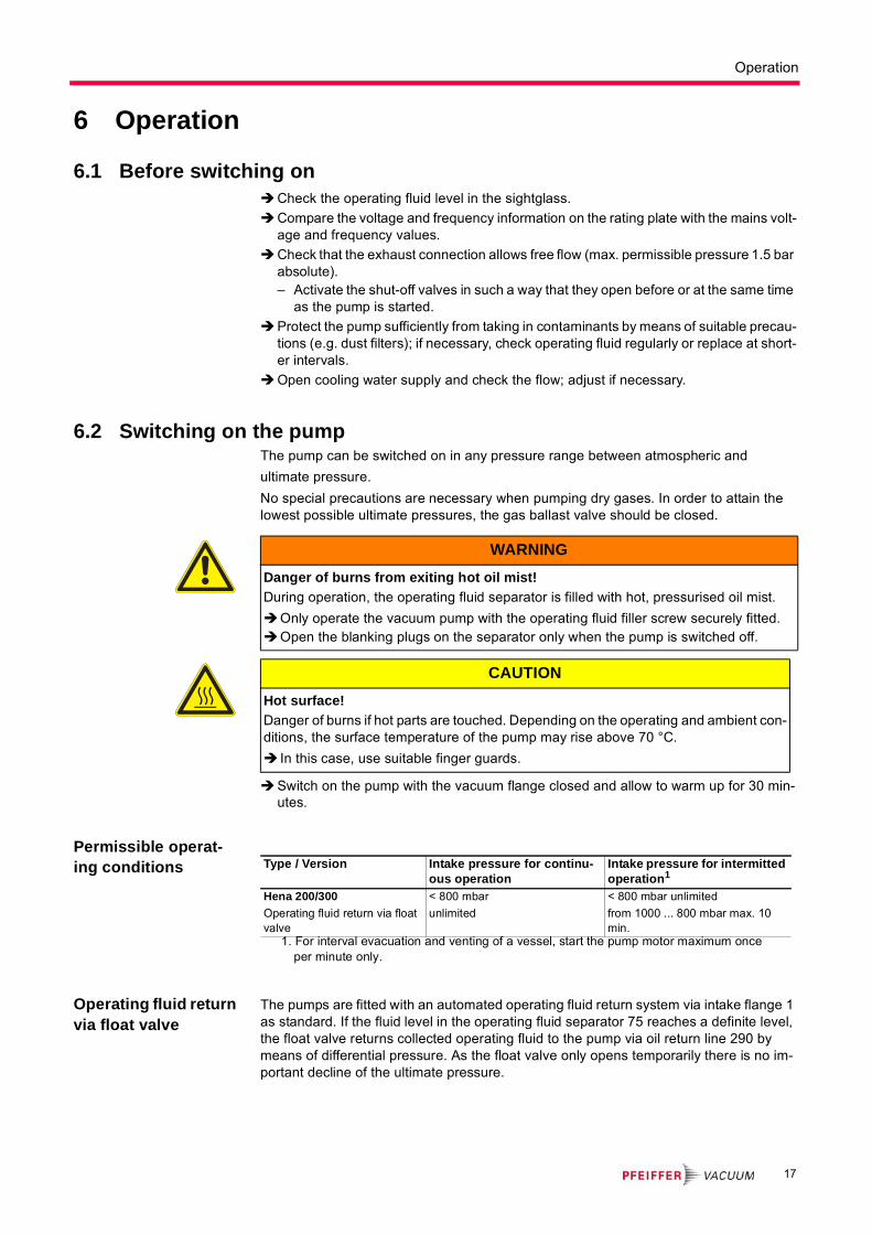
Permissible operat-ing conditions
Operating fluid return via float valve
The pumps are fitted with an automated operating fluid return system via intake flange 1 as standard. If the fluid level in the operating fluid separator 75 reaches a definite level, the float valve returns collected operating fluid to the pump via oil return line 290 by means of differential pressure. As the float valve only opens temporarily there is no im-portant decline of the ultimate pressure.
WARNING
Danger of burns from exiting hot oil mist!
During operation, the operating fluid separator is filled with hot, pressurised oil mist.
Only operate the vacuum pump with the operating fluid filler screw securely fitted.Open the blanking plugs on the separator only when the pump is switched off.
CAUTION
Hot surface!
Danger of burns if hot parts are touched. Depending on the operating and ambient con-ditions, the surface temperature of the pump may rise above 70 °C.
In this case, use suitable finger guards.
Type / Version Intake pressure for continu-ous operation
Intake pressure for intermitted operation1
1. For interval evacuation and venting of a vessel, start the pump motor maximum once per minute only.
Hena 200/300
Operating fluid return via float valve
< 800 mbar
unlimited
< 800 mbar unlimited
from 1000 ... 800 mbar max. 10 min.
17

Operation
6.3 Pumping condensable vapoursShould the process gases contain condensable gases present at high percentages, the rotary vane pump must be operated with gas ballast (i.e. with an open gas ballast valve).
Pumping condens-able vapours
To avoid condensation in the pump when pumping condensable vapours, air is periodi-cally fed into the working chamber at the beginning of the compression phase via the gas ballast valve 477.
The gas ballast valve is closed when turning to the right to position 0 and open when turn-ing to the left to position 1. Intermediate settings are not possible.
Fig. 8: Gas ballast valve for Hena 200/300
NOTE
The operating fluid return only works properly if the working pressure is
< 800 mbar.
CAUTION
Bad final vacuum and damage to the pump!
Danger of condensation and corrosion due to exceeding the water vapour compatibility during operation without gas ballast or in case of insufficient supply of flushing gas.
Only pump vapours when the pump is warm and the gas ballast valve is open.When the process has been completed, allow the pump to continue running for
about 30 minutes with the vacuum flange closed and the gas ballast open for oper-ating fluid regeneration purposes.
477Gas ballast valve
477
"1""0"
18

Operation
6.4 Switching off the pumpThe pump can be switched off in any pressure range.
Rotary vane pumps have an integrated safety valve on the intake side. If the differential pressure between the exhaust side and the intake side is ≥ 250 mbar, then the valve clos-es automatically and vents the pump when the pump is switched off.
Switch the pump off at the mains switch or disconnect from the mains in a secure man-ner.
Venting the vacuum chamber
Maintaining the vac-uum in the chamber
CAUTION
Danger of backflow of operating fluid into the intake line!
Contamination of the connected vacuum system!
Vent the vacuum chamber within 30 s, regardless of the chamber size.For a longer venting process, use an additional shut-off valve and shut off the intake
line after switching off the pump.
CAUTION
Danger of backflow of operating fluid into the intake line!
Contamination of the connected vacuum system!
Because the safety valve of the pump is not suitable for longer-term sealing, install an additional shut-off valve in the intake line.
Shut off the intake line immediately after switching off the pump.
19

Maintenance
7 Maintenance
7.1 Precautions
Turn off the vacuum pump, vent to atmospheric pressure and allow to cool, if neces-sary.
Disconnect the drive motor from the mains and secure it so that it cannot be switched on.
Only dismantle the pump as far as necessary in order to repair defects.
Dispose of used operating fluid in compliance with local regulations.
When using synthetic operating fluids or working with toxic substances or substances contaminated with corrosive gases, the relevant instructions governing their use must be observed.
Use only alcohol or similar agents for cleaning pump parts.
WARNING
Danger of injury from moving parts!
After power failure or motor shutdown due to overheating, the motor may restart auto-matically.
Secure the motor so that it cannot be switched on while any work is being performed on the pump.
If necessary, dismantle the pump from the installation for inspection.
WARNING
Pump parts may be contaminated from pumped media!
Danger of poisoning due to contact with harmful substances.
Decontaminate the pump before carrying out any maintenance work. In the event of contamination, take suitable safety precautions to prevent your health
from being harmed by any dangerous substances.
NOTE
Service work should be carried out by qualified personal only!
Pfeiffer Vacuum is not liable for any damage to the pump resulting from work carried out improperly.
Take advantage of our service training programs; additional information at www.pfei-ffer-vacuum.com.
Please state all the information on the pump rating plate when ordering spare parts.
20

Maintenance
Checklist for inspec-tion, maintenance and overhaul
Certain repair and overhaul work should only be performed by Pfeiffer Vacuum Service (PV). Pfeiffer Vacuum will be released from all warranty and liability claims if the required intervals for inspection, maintenance, or overhaul are exceeded or inspection, mainte-nance, repair or overhaul procedures are not performed properly. This also applies if re-placement parts other than Pfeiffer Vacuum OEM replacement parts are used.
7.2 Changing the operating fluidThe changing interval for the operating fluid depends on the pump applications, but should be carried out once a year.
The level of deterioration of operating fluid P3 can be determined for clean processes with the colour scale (in accordance with DIN 51578); supplementary sheet PK 0219 BN on request or download it from the Internet.
Suck off operating fluid from the pump through the operating fluid filler opening.
Fill the specimen in a test tube or some similar vessel and test by holding against the light.
Where discolouration is dark yellow to red brown (equivalent to 4 ... 5 on the scale) change operating fluid.
Switch off the pump.
Unscrew operating fluid filler screw 88.
Unscrew operating fluid drain screw 95.
Ac
tivi
ty
da
ily
as r
equ
ire
d;
at
lea
st
on
ce
ev
ery
6 m
on
ths
as r
equ
ire
d;
at l
eas
t an
nu
all
y
as r
equ
ire
d;
at l
eas
t ev
ery
2 y
ea
rs
as r
equ
ire
d;
at l
eas
t ev
ery
4 y
ea
rs
Check operating fluid level X
Visual inspection (leak-tightness/oil leaks) X
Check the saturation of the exhaust air filter (internal oil mist filter)
X
Change operating fluid X
Change operating fluid filter X
Change the exhaust air filter X
Cleaning the pump and renew the o-rings X
Clean gas ballast valve X
Clean the fan cap of the motor X
Replace the radial shaft seals1
1. Where unusually high levels of operating fluid are being lost it is necessary to carry out a check of the radial shaft seals. If operating fluid leaks out from under the pump between the pump casing and the motor or fan, the radial shaft seals should be replaced. In this case please get in touch with your local Pfeiffer Vacuum Service.
X (PV)
Clean or replace discharge valves X (PV)
Replace vanes X (PV)
Replace vacuum safety valve X (PV)
Check or change coupling X (PV)
Depending on the process, the required replacement intervals for lubricants and the intervals for inspection,maintenance and overhaul may be shorter than the guide values specified in the table. Consult with PfeifferVacuum Service if necessary.
NOTE
Depending on the applications, Pfeiffer Vacuum recommends determining the ex-act service life of the operating fluid during the first year of operation.
The replacement interval may vary from the guide value specified by Pfeiffer Vacuum depending on the thermal and chemical loads, and the accumulation of suspended par-ticles and condensation in the operating fluid.
21

Maintenance
Fig. 9: Filling up the operating fluid
Screw in operating fluid drain screw 95; pay attention to O-ring.
Screw in operating fluid filler screw 88.
Allow pump to run for a maximum of 5 seconds with the vacuum flange open.
Drain off remaining operating fluid.– In case of serious contamination, the operating fluid will have to be changed sev-
eral times (flushing):
Flushing Fill up with operating fluid to the middle of the sight glass.
Operate the pump with the gas ballast open until the pump has warmed up.
Drain the operating fluid again and check for contamination, flush again if necessary.
Screw the operating fluid drain screw back in.
Fill up with operating fluid and check the filling level (see p. 14, chap. ).
Changing the operat-ing fluid filter
Operating fluid filter 100 should be replaced at every operating fluid change but at least once every six months. It is also necessary to replace the filter when the pump is on op-erating temperature and the filter housing is cold.
Allow the pump to warm up for a minimum of 15 minutes before replacing the filter.
Switch off the pump.
83 Sight glass88 Operating fluid filler screw
(manometer)95 Operating fluid drain screw
88
83
95
Max.
Min.
WARNING
Hot operating fluid!
Danger of burns when draining due to contact with skin.
Wear suitable protective clothing.Use a suitable collecting vessel.
WARNING
Operating fluid may contain toxic substances from the pumped media!
Danger of poisoning from the emission of harmful substances from the operating fluid.
Wear suitable protective clothing and respirators.Dispose of operating fluid according to the local regulations
NOTE
Request safety data sheets for operating fluids and lubricants
from Pfeiffer Vacuum or download them from the Internet.
Dispose of operating fluid according to the local regulations.
22
Maintenance
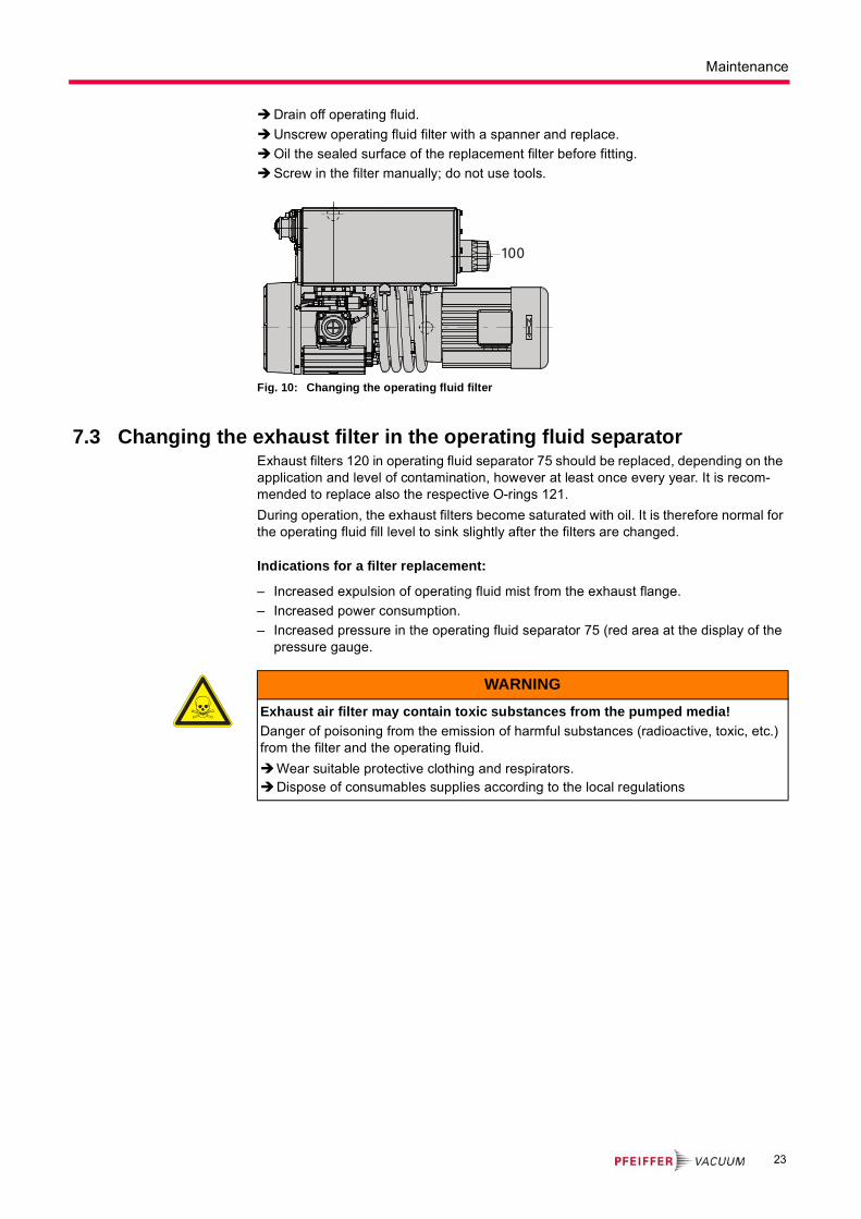
Drain off operating fluid.
Unscrew operating fluid filter with a spanner and replace.
Oil the sealed surface of the replacement filter before fitting.
Screw in the filter manually; do not use tools.
Fig. 10: Changing the operating fluid filter
7.3 Changing the exhaust filter in the operating fluid separatorExhaust filters 120 in operating fluid separator 75 should be replaced, depending on the application and level of contamination, however at least once every year. It is recom-mended to replace also the respective O-rings 121.
During operation, the exhaust filters become saturated with oil. It is therefore normal for the operating fluid fill level to sink slightly after the filters are changed.
Indications for a filter replacement:
– Increased expulsion of operating fluid mist from the exhaust flange.
– Increased power consumption.
– Increased pressure in the operating fluid separator 75 (red area at the display of the pressure gauge.
100
WARNING
Exhaust air filter may contain toxic substances from the pumped media!
Danger of poisoning from the emission of harmful substances (radioactive, toxic, etc.) from the filter and the operating fluid.
Wear suitable protective clothing and respirators.Dispose of consumables supplies according to the local regulations
23

Maintenance
Fig. 11: Operating fluid separator
Dismantling Turn off the vacuum pump, vent to atmospheric pressure and allow to cool, if neces-sary.
Remove exhaust line.
Unscrew screws 142 from separator cover 140; take care with the spring washer 143!
Remove separator cover 140.
Remove fixing bolt 137.
Remove grid 136 and filter 130.
Remove nut 134 and washer 132.
Remove exhaust filter unit and filter support 118 from the separator box and set down on an even, clean surface.
15975
206
205208
207
176175
169
nur für Ausführung Hena 300version Hena 300 only
75 Operating fluid separator83 Sight glass84 Flat seal88 Operating fluid filler screw89 O-ring95 Operating fluid drain screw96 O-ring100 Operating fluid filter115 Clamping plate118 Filter support119 O-ring120 Exhaust filter121 O-ring126 Screw128 Lock washer
130 Filter131 Stud132 Lock washer133 Pipe134 Hexagon nut136 Grid137 Fixing bolt140 Separator cover141 Flat seal142 Cylinder head screw146 Hexagon head screw152 Spring washer154 Cover seal169 Valve covering plate194 Float valve
195 Support for level switch196 Set screw197 O-ring198 Cylinder head screw238 Cylinder head screw241 Cooler242 O-ring244 Protective cover247 Screw321 Radial fan326 Notched ring353 Cylinder head screw557 Filter
24

Maintenance
Undo screws 126 and lock washers 128 and clamping plate 115.
Assembling Insert new exhaust filter with new O-rings 119 into filter support 118; observe direction of arrow on the exhaust filter.
Fit clamping plate 115 and tighten the two screws 126; ensure pipe 133 is correctly seated.
Fit pre-mounted waste air filter unit into separator box; observe guide on stud screw 131.
Fit washer 132 and tighten hexagon nut 134.
Replace grid 136 and filter 130 and insert into the guide rail of the separator box;– Push filter material onto the floor and make sure it is in contact with all sides of the
separator box.
Insert fixing bolt 137 into the guide notch.
Check filter 557 in threaded flange; replace if necessary.
Install separator cover 140, ensure that flat seal 141 is clean and undamaged; ex-change if necessary.
7.4 Cleaning the float valveThe float valve (1x) must be checked and cleaned each time the operating fluid is changed.
Drain off operating fluid.
Undo the two screws 247 and remove the protective cover 244 above fan impellers.
Remove lock washer 326 and fan 321.
Undo screws 238 and 353 and remove lock washers.
Remove cooler 241.
Check O-rings 242 and replace if necessary.
Undo the two fixing screws 198 on the float valve and remove the entire unit.
Undo set screw 196 and remove float valve 194; check for functioning and clean with compressed air if necessary.
Check O-ring 197 and replace if necessary.
Refit float valve 194; pay attention to proper mounting orientation.
25

Maintenance
7.5 Changing the intake filterThe intake filter, located in the upper part of the intake flange must be cleaned when the intake throughput reduces.
Unscrew screws 265 from the vacuum flange and dismantle flange
Remove intake sieve 261 from the intake port and clean it.
When cleaning the sieve it is recommended to clean the vacuum safety valve at the same time and check it for wear and tear.
7.6 Changing the gas ballast filterThe gas ballast filter is used to keep the air free of particles before entering the suction chamber.
Fig. 12: Gas ballast valve for Hena 200/300
Check gas ballast valve and line for free flow.
If no further air is sucked in, dismount gas ballast filter 474 and blow out with com-pressed air.
7.7 Cleaning the fan covers and radiatorContamination prevents the flow of cool air and can lead to the vacuum pump overheat-ing.
Check cooler, ventilator cowl and motor cover for dirt on a regular basis; clean, if nec-essary.
477Gas ballast valve474 Gas ballast filter
26
Decommissioning
8 Decommissioning
8.1 Shutting down for longer periodsBefore shutting down the pump, observe the following procedure and adequately protect the pump system against corrosion:
Switch off the pump.
Change the operating fluid (see p. 21, chap. 7.2).Start the pump and allow the pump to warm up with closed vacuum flange and with
open gas ballast valve.
Close gas ballast valve.
Blow compressed air through the cooling water system and completely empty cooling water channels to avoid rust and frost damage.
8.2 Re-starting
8.3 DisposalProducts or parts thereof (mechanical and electrical components, operating fluids, etc.) may cause environmental burden.
Safely dispose of the materials according to the locally applicable regulations.
9 MalfunctionsPlease note the following instructions should the pump malfunction:
CAUTION
Emission of operating fluid!
Danger of the operating fluid being emitted at the exhaust flange if overfilled.
Drain the operating fluid to the normal level before restarting the pump.
CAUTION
Re-starting
The serviceability of the operating fluid without operation is a maximum of 2 years. Be-fore restarting after a shut-down of 2 years or longer, carry out the following work.
Replace the operating fluid.Replace the radial shaft sealing rings and further elastomer parts.Replace bearings at pumps with anti-friction bearings.Follow the maintenance instructions and inform Pfeiffer Vacuum.
CAUTION
Hot surface!
Danger of burns if hot parts are touched. The surface temperature of the pump may rise above 105 °C in case of malfunction.
Carry out work on the pump only after it has cooled to a safe temperature.
27

Malfunctions
9.1 Rectifying malfunctions
NOTE
Motor overload!
Depending on the malfunction (e.g. blocking during cold start), the motor may not be sufficiently protected by the built-in thermal protection switch from damage through overheating.
Implement an additional network safety device.
Problem Possible causes Remedy
Pump will not start up No mains voltage or voltage does not correspond to the motor data
Check mains voltage and mains fuse protec-tion; check motor switch
Pump temperature too low Warm up pump to > 12°C
Thermal protection switch has re-sponded
Detect and fix cause of overheating; allow pump to cool off if necessary.
Pump system dirty Clean pump; contact Pfeiffer Vacuum Ser-vice if necessary.
Pump system damaged Clean and overhaul pump; contact Pfeiffer Vacuum Service if necessary.
Motor defective Replace motor
Pump switches off af-ter a while after being started
Thermal protection switch of the motor has responded
Detect and fix cause of overheating; allow motor to cool off if necessary.
Mains fuse protection triggered due to overload (e.g. cold start)
Warm up pump
Exhaust pressure too high Check opening of exhaust line and exhaust accessories
Pump does not attain ultimate pressure
Measurement reading is false Check gauge, check ultimate pressure with-out installation connected.
Pump or connected accessories are dirty
Clean pump and check components for con-tamination.
Operating fluid dirty Operate pump for a longer period with gas ballast valve open or change operating fluid
Leak in system Repair leak
Operating fluid filling level too low Top off operating fluid
Pump damaged Contact Pfeiffer Vacuum Service.
Pumping speed of pump too low
Intake line not well-dimensioned Keep connections as short as possible and see that cross-sections are sufficiently di-mensioned
Exhaust pressure too high Check opening of exhaust line and exhaust accessories
Loss of operating fluid Operating fluid separator leaky Check tightness; replace gasket if neces-sary
Radial shaft seal rings leaky Replace seal ring and check bushing
Operational loss of operating fluid Check the oil return unit
Unusual operating noises
Silencer dirty Clean or replace the silencer.
Damage to the pump system Clean and overhaul pump; contact Pfeiffer Vacuum Service if necessary.
Motor bearing defective Replace motor; contact Pfeiffer Vacuum Service if necessary
NOTE
Service work should be carried out by qualified personal only!
Pfeiffer Vacuum is not liable for any damage to the pump resulting from work carried out improperly.
Take advantage of our service training programs; additional information at www.pfei-ffer-vacuum.com.
Please state all the information on the pump rating plate when ordering spare parts.
28

Service
10 ServicePfeiffer Vacuum offers first-class service!
● Maintenance/repairs on site by Pfeiffer Vacuum field service
● Maintenance/repairs in a nearby service center or service point
● Fast replacement with exchange products in mint condition
● Advice on the most cost-efficient and quickest solution
Detailed information and addresses at: www.pfeiffer-vacuum.com (Service).
Maintenance and repairs in Pfeiffer Vacuum ServiceCenter
The following steps are necessary to ensure a fast, smooth servicing process:
Download the forms "Service Request" and "Declaration on Contamination".1)
Fill out the "Service Request" form and send it by fax or e-mail to your
Pfeiffer Vacuum service address.
Include the confirmation on the service request from Pfeiffer Vacuum with your ship-ment.
Fill in the contamination declaration and enclose it in the shipment (required!).
Dismantle all accessories.
Drain operating fluid/lubricant.
Drain cooling medium, if used.
Send the pump or unit in its original packaging if possible.
Sending of contaminated pumps or devices
No units will be accepted if they are contaminated with micro-biological, explosive or ra-dioactive substances. “Hazardous substances” are substances and compounds in ac-cordance with the hazardous goods directive (current version). If pumps are contaminat-ed or the declaration on contamination is missing, Pfeiffer Vacuum performs decontamination at the shipper's expense.
Neutralise the pump by flushing it with nitrogen or dry air.
Close all openings airtight.
Seal the pump or unit in suitable protective film.
Return the pump/unit only in a suitable and sturdy transport container and send it in while following applicable transport conditions.
Service orders
All service orders are carried out exclusively according to our repair conditions for vacu-um units and components.
1) Forms under www.pfeiffer-vacuum.com
29

Spare parts
11 Spare parts
Fig. 13: Exploded view Hena 200/300
XX
*: n
ur fü
r Aus
führ
ung
Hen
a 30
0
v
ersi
on H
ena
300
only
* :
Gas
balla
st E
inze
lteile
gas
bal
last
com
pone
nts
3
30

Accessories
11.1 Spare parts packages
12 Accessories
Further detailed accessories are contained in the Pfeiffer Vacuum printed or Online Cat-alogue.
7 O-ring18 Inner ring22 Vane30 Needle bearing without
inner ring35 Radial shaft seal49 O-ring50 O-ring60 Taper pin61 Cylinder pin84 Flat seal88 Operating fluid filler
screw
89 Sealing ring89 O-ring95 Operating fluid drain
screw96 O-ring100 Operating fluid filter106 Flat seal119 O-ring120 Exhaust filter121 O-ring130 Filter136 Grid141 Flat seal
154 Cover seal159 Exhaust valve162 Cap gasket185 Flat seal197 O-ring206 Flat seal242 O-ring253 O-ring255 O-ring261 Intake sieve312 Coupling sleeve326 Notched ring
Spare parts package Pump type No.
Set of seals Hena 200 PK E60 022 -T
Maintenance kit Hena 200 PK E61 022 -T
Overhaul kit Hena 200 PK E62 024 -T
Set of vanes Hena 200 PK E68 024 -T
Pressure gauge for exhaust pressure control
Hena 200 PK 100 127
Operating fluid filter Hena 200 P 0920 591 E
Spare parts package Pump type Nr.
Set of seals Hena 300 PK E60 023 -T
Maintenance kit Hena 300 PK E61 022 -T
Overhaul kit Hena 300 PK E62 025 -T
Set of vanes Hena 300 PK E68 025 -T
Pressure gauge for exhaust pres-sure control
Hena 300 PK 100 127
Operating fluid filter Hena 300 P 0920 591 E
Designation Hena 200 Hena 300
SAS 100, DN 100 ISO-K, polyester filter PK Z60 512 PK Z60 512
Operating fluid level monitoring PK 100 116 PK 100 116
Barretter actuation unit 3TF P 4768 051 FQ P 4768 051 FQ
P3, mineral oil, 1 l PK 001 106-T PK 001 106-T
P3, mineral oil, 5 l PK 001 107-T PK 001 107-T
P3, mineral oil, 20 l PK 001 108-T PK 001 108-T
P3, mineral oil, 50 l PK 001 109-T PK 001 109-T
P3, mineral oil, 200 l PK 001 110-T PK 001 110-T
31

Technical data
13 Technical dataParameter Hena 200 Hena 300Flange (in) DN 100 ISO-K DN 100 ISO-K
Flange (out) DN 100 ISO-K DN 100 ISO-K
Pumping speed at 50 Hz 200 m3/h 300 m3/h
Pumping speed at 60 Hz 240 m3/h 360 m3/h
Ultimate pressure with gas ballast 0.7 mbar 0.7 mbar
Ultimate pressure without gas ballast 0.3 mbar 0.3 mbar
Nominal rotation speed at 50 Hz 1500 rpm 1500 rpm
Nominal rotation speed at 60 Hz 1800 rpm 1800 rpm
Emission sound pressure level with-out gas ballast at 50 Hz
72 dB (A) 74 dB (A)
Emission sound pressure level with-out gas ballast at 60 Hz
74 dB (A) 76 dB (A)
Relative humidity of air 95 % 95 %
Rated power 50 Hz 5.5 kW 8.3 kW
Rated power 60 Hz 6.3 kW 10 kW
Mains requirement: voltage 50 Hz 190-208/220-240/380-415 V 190-208/220-240/380-415 V
Mains requirement: voltage 60 Hz 220-230/440-460 V 220-230/440-460 V
Switch No No
Altitude of site, max 1000 m 1000 m
Exhaust pressure, max. 1500 abs. mbar 1500 abs. mbar
Exhaust pressure, min. 1000 abs. mbar 1000 abs. mbar
Leak rate safety valve 0.08 mbar l/s 0.08 mbar l/s
Ambient temperature 12-40 °C 12-40 °C
Operating fluid filling 6.5 l 6.5 l
Weight 182 kg 228 kg
32

Technical data
13.1 Dimensions
Fig. 14: Hena 200
±1.5 ±1.5
±1.5
±1.5
DN 100 ISO-K
DN 100 ISO-K
447
315
418
15
30592
(...): motor efficiency class IE2
4 x M10
997 (989)
1001 (1004)
292
263307
258127
39040
578
(582
)
33
Technical data
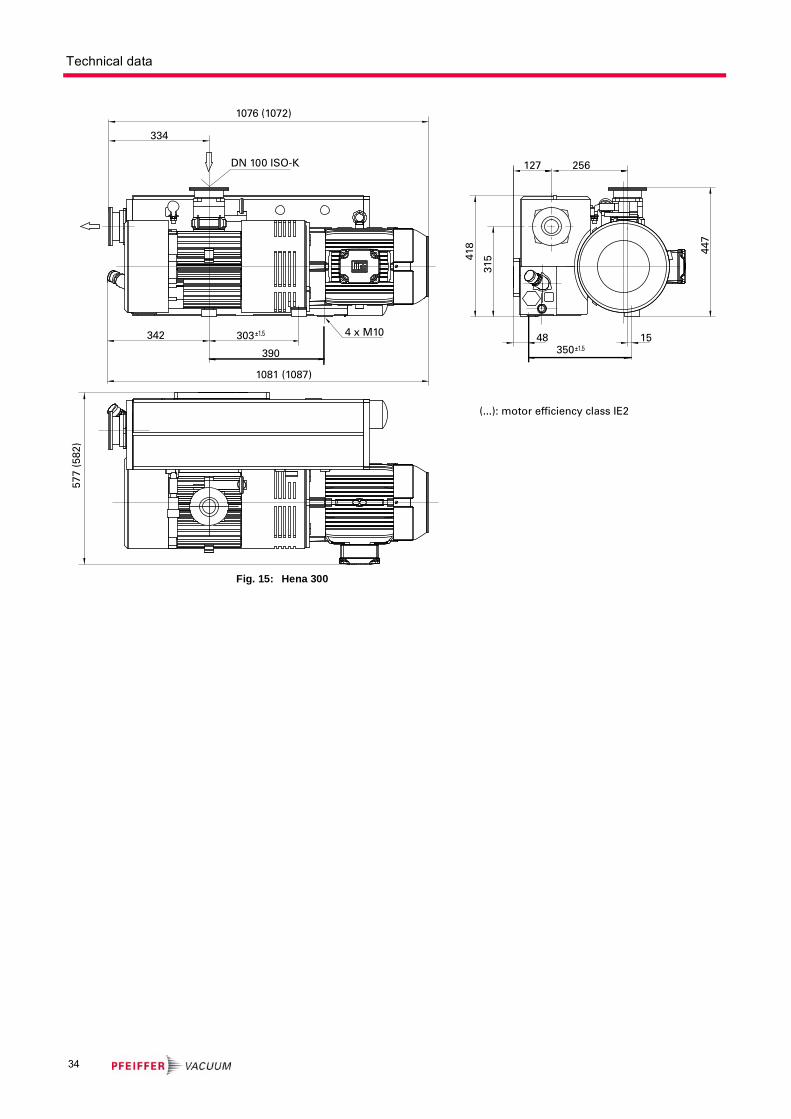
Fig. 15: Hena 300
DN 100 ISO-K
±1.5
±1.51548
350
256127
418
315
447
342
390
303 4 x M10
577
(58
2)
1076 (1072)
1081 (1087)
334
(...): motor efficiency class IE2
34

Declaration of conformity
according to the EC directive:
● Machinery 2006/42/EC (Annex II, no. 1 A)
We hereby declare that the product cited below satisfies all relevant provisions of EC directive "Machinery" 2006/42/EC.
In addition, the product cited below satisfies all relevant provisions of EC directive "Elec-tromagnetic Compatibility" 2004/108/EC .
The agent responsible for compiling the technical documentation is Mr. Sebastian Ober-beck, Pfeiffer Vacuum GmbH, Berliner Straße 43, 35614 Aßlar.
HenaLine™
Hena 200/300
Guidelines, harmonised standards and national standards and specifications which have been applied:
DIN EN ISO 12100 : 2011-03 DIN EN ISO 2151 : 2009 DIN EN 61000-6-3 : 2007
DIN EN 1012-1 : 2007 DIN EN ISO 13857 : 2008 DIN EN 61000-6-4 : 2007
DIN EN 1012-2 : 1996 DIN EN 61000-6-1 : 2007
DIN EN ISO 14121-1 : 2007 DIN EN 61000-6-2 : 2006
Signatures:
Pfeiffer Vacuum GmbH
Berliner Straße 43
35614 Asslar
Germany
(M.Bender)
Managing Director
(Dr. M. Wiemer)
Managing Director
CE/2011
You are perfect vPlease c
Leading. Customer
looking for aacuum solution?ontact us:
GermanyPfeiffer Vacuum GmbHHeadquartersTel.: +49 (0) 6441 [email protected]
BeneluxPfeiffer Vacuum GmbHSales & Service BeneluxTel.: [email protected]
ChinaPfeiffer Vacuum(Shanghai) Co., Ltd.Tel.: +86 21 3393 [email protected]
FrancePfeiffer Vacuum France SASTel.: +33 169 30 92 82
Great BritainPfeiffer Vacuum Ltd.Tel.: +44 1908 [email protected]
IndiaPfeiffer Vacuum India Ltd.Tel.: +91 40 2775 [email protected]
ItalyPfeiffer Vacuum Italia S.p.A.Tel.: +39 02 93 99 05 [email protected]
KoreaPfeiffer Vacuum Korea Ltd.Tel.: +82 31 266 0741
AustriaPfeiffer Vacuum Austria GmbHTel.: +43 1 894 17 [email protected]
SwedenPfeiffer Vacuum Scandinavia ABTel.: +46 8 590 748 [email protected]
SwitzerlandPfeiffer Vacuum (Schweiz) AGTel.: +41 44 444 22 [email protected]
United StatesPfeiffer Vacuum Inc.Tel.: +1 603 578 6500
Pfeiffer Vacuum stands for innovative and customvacuum solutions worldwide. For German engineering art,competent advice and reliable services.
Ever since the invention of the turbopump, we´vebeen setting standards in our industry. And this claimto leadership will continue to drive us in the future.
Dependable. Friendly
[email protected] [email protected] [email protected]
www.pfeiffer-vacuum.com