Operating Instructions for EL1904 - Beckhoff · PDF fileOperating Instructions for EL1904 ......
46
Operating Instructions for EL1904 TwinSAFE Terminal with 4 digital fail-safe inputs 2.1.1 2017-02-07 Version: Date:
-
Upload
nguyenthien -
Category
Documents
-
view
230 -
download
2
Transcript of Operating Instructions for EL1904 - Beckhoff · PDF fileOperating Instructions for EL1904 ......

Operating Instructions for
EL1904
TwinSAFE Terminal with 4 digital fail-safe inputs
2.1.12017-02-07
Version:Date:


Table of contents
EL1904 3Version: 2.1.1
Table of contents1 Foreword .................................................................................................................................................... 5
1.1 Notes on the documentation........................................................................................................... 51.2 Safety instructions .......................................................................................................................... 6
1.2.1 Delivery state ..................................................................................................................... 61.2.2 Operator's obligation to exercise diligence ........................................................................ 61.2.3 Description of safety symbols ............................................................................................ 7
1.3 Documentation issue status............................................................................................................ 8
2 System description ................................................................................................................................... 92.1 The Beckhoff Bus Terminal system ................................................................................................ 9
2.1.1 Bus Coupler ..................................................................................................................... 102.1.2 Bus Terminals .................................................................................................................. 112.1.3 E-bus................................................................................................................................ 112.1.4 Power contacts................................................................................................................. 11
2.2 TwinSAFE..................................................................................................................................... 122.2.1 The I/O construction kit is extended safely ...................................................................... 122.2.2 Safety concept ................................................................................................................. 122.2.3 EL1904, EL2904 - Bus Terminals with 4 fail-safe inputs or outputs ................................ 132.2.4 EL6900 - TwinSAFE logic terminal .................................................................................. 132.2.5 The fail-safe principle (Fail Stop) ..................................................................................... 13
3 Product description................................................................................................................................. 143.1 EL1904 – TwinSAFE terminal with 4 digital fail-safe inputs.......................................................... 143.2 Intended use ................................................................................................................................. 143.3 Technical data .............................................................................................................................. 163.4 Safety parameters ........................................................................................................................ 173.5 Characteristic curve of the inputs ................................................................................................. 173.6 Dimensions ................................................................................................................................... 183.7 Block diagram of the EL1904........................................................................................................ 18
4 Operation.................................................................................................................................................. 194.1 Environmental conditions.............................................................................................................. 194.2 Installation..................................................................................................................................... 19
4.2.1 Safety instructions............................................................................................................ 194.2.2 Transport / storage........................................................................................................... 194.2.3 Mechanical installation..................................................................................................... 194.2.4 Electrical installation......................................................................................................... 234.2.5 TwinSAFE reaction times................................................................................................. 294.2.6 Tested EL1904 devices ................................................................................................... 30
4.3 Operation in potentially explosive atmospheres (ATEX) .............................................................. 314.3.1 Special conditions ............................................................................................................ 314.3.2 Identification..................................................................................................................... 324.3.3 Date code and serial number........................................................................................... 324.3.4 Further ATEX documentation .......................................................................................... 32
4.4 Configuration of the terminal in TwinCAT ..................................................................................... 324.4.1 Inserting a Bus Coupler ................................................................................................... 324.4.2 Inserting a Bus Terminal .................................................................................................. 334.4.3 Inserting an EL1904......................................................................................................... 334.4.4 Address settings on TwinSAFE terminals with 65535 possible addresses...................... 344.4.5 Entering a TwinSAFE address and parameters in the System Manager......................... 35
4.5 Diagnostics ................................................................................................................................... 39

Table of contents
EL19044 Version: 2.1.1
4.5.1 Diagnostic LEDs............................................................................................................... 394.5.2 Diagnostic objects ............................................................................................................ 40
4.6 Maintenance ................................................................................................................................. 414.7 Service life .................................................................................................................................... 424.8 Decommissioning ......................................................................................................................... 42
5 Appendix .................................................................................................................................................. 435.1 Support and Service ..................................................................................................................... 435.2 Certificates.................................................................................................................................... 44

Foreword
EL1904 5Version: 2.1.1
1 Foreword
1.1 Notes on the documentation
Intended audience
This description is only intended for the use of trained specialists in control and automation engineering whoare familiar with the applicable national standards.
It is essential that the following notes and explanations are followed when installing and commissioningthese components.
The responsible staff must ensure that the application or use of the products described satisfy all therequirements for safety, including all the relevant laws, regulations, guidelines and standards.
Origin of the document
This documentation was originally written in German. All other languages are derived from the Germanoriginal.
Currentness
Please check whether you are using the current and valid version of this document. The current version canbe downloaded from the Beckhoff homepage at http://www.beckhoff.com/english/download/twinsafe.htm.In case of doubt, please contact Technical Support [} 43].
Product features
Only the product features specified in the current user documentation are valid. Further information given onthe product pages of the Beckhoff homepage, in emails or in other publications is not authoritative.
Disclaimer
The documentation has been prepared with care. The products described are subject to cyclical revision. Forthat reason the documentation is not in every case checked for consistency with performance data,standards or other characteristics. We reserve the right to revise and change the documentation at any timeand without prior announcement. No claims for the modification of products that have already been suppliedmay be made on the basis of the data, diagrams and descriptions in this documentation.
Trademarks
Beckhoff®, TwinCAT®, EtherCAT®, Safety over EtherCAT®, TwinSAFE®, XFC® and XTS® are registeredtrademarks of and licensed by Beckhoff Automation GmbH.Other designations used in this publication may be trademarks whose use by third parties for their ownpurposes could violate the rights of the owners.
Patent Pending
The EtherCAT Technology is covered, including but not limited to the following patent applications andpatents: EP1590927, EP1789857, DE102004044764, DE102007017835 with corresponding applications orregistrations in various other countries.
The TwinCAT Technology is covered, including but not limited to the following patent applications andpatents: EP0851348, US6167425 with corresponding applications or registrations in various other countries.

Foreword
EL19046 Version: 2.1.1
EtherCAT® is registered trademark and patented technology, licensed by Beckhoff Automation GmbH,Germany
Copyright
© Beckhoff Automation GmbH & Co. KG, Germany.The reproduction, distribution and utilization of this document as well as the communication of its contents toothers without express authorization are prohibited.Offenders will be held liable for the payment of damages. All rights reserved in the event of the grant of apatent, utility model or design.
Delivery conditions
In addition, the general delivery conditions of the company Beckhoff Automation GmbH & Co. KG apply.
1.2 Safety instructions
1.2.1 Delivery stateAll the components are supplied in particular hardware and software configurations appropriate for theapplication. Modifications to hardware or software configurations other than those described in thedocumentation are not permitted, and nullify the liability of Beckhoff Automation GmbH & Co. KG.
1.2.2 Operator's obligation to exercise diligenceThe operator must ensure that
• the TwinSAFE products are only used as intended (see chapter Product description);• the TwinSAFE products are only operated in sound condition and in working order.• the TwinSAFE products are operated only by suitably qualified and authorized personnel.• the personnel is instructed regularly about relevant occupational safety and environmental protection
aspects, and is familiar with the operating instructions and in particular the safety instructions containedherein.
• the operating instructions are in good condition and complete, and always available for reference at thelocation where the TwinSAFE products are used.
• none of the safety and warning notes attached to the TwinSAFE products are removed, and all notesremain legible.

Foreword
EL1904 7Version: 2.1.1
1.2.3 Description of safety symbolsIn these operating instructions the following symbols are used with an accompanying safety instruction ornote. The safety instructions must be read carefully and followed without fail!
DANGER
Serious risk of injury!Failure to follow the safety instructions associated with this symbol directly endangers thelife and health of persons.
WARNING
Risk of injury!Failure to follow the safety instructions associated with this symbol endangers the life andhealth of persons.
CAUTION
Personal injuries!Failure to follow the safety instructions associated with this symbol can lead to injuries topersons.
Attention
Damage to the environment or devicesFailure to follow the instructions associated with this symbol can lead to damage to the en-vironment or equipment.
Note
Tip or pointerThis symbol indicates information that contributes to better understanding.

Foreword
EL19048 Version: 2.1.1
1.3 Documentation issue statusVersion Comment2.1.1 • Technical data permissible air pressure expanded2.1.0 • Chapter Address settings on TwinSAFE terminals with 65535 possible addresses updated
• Links in technical data corrected2.0.0 • Migration and structural adaptation
• Reliability document updated• Safety parameters updated• Foreword revised
1.5.2 • Block diagram updated• Numbering/table of contents changed (Chapter 4.1.5 to 4.1.7)• Description of the test pulses added• Description of the reaction times added• Reliability document updated
1.5.1 • Certificate updated1.5.0 • Company address amended
• Safety parameters extended1.4.0 • Extended temperature range added
• Temperature measurement described• Characteristic input curve added• Description of date code extended
1.3.1 • Document origin added1.3.0 • Clock output currents in the technical data amended
• Block diagram for EL1904 added1.2.1 • Reference to EN 60068-2-29 removed1.2.0 • ATEX notes amended
• Installation position / minimum distances extended• Notes regarding overvoltage protection amended• Notes regarding cable length and clocked signals extended• Diagnostics for CoE object 0x800E described
1.1.0 • Minor amendments for EtherCAT• Copyright / disclaimer modified• Support / service addresses updated
1.0.0 • First released version

System description
EL1904 9Version: 2.1.1
2 System description
2.1 The Beckhoff Bus Terminal systemThe Beckhoff Bus Terminal system is used for decentralized connection of sensors and actuators to acontrol system. The Beckhoff Bus Terminal system components are mainly used in industrial automation andbuilding management applications. In its minimum configuration, a bus station consists of a Bus Coupler or aBus Terminal Controller and Bus Terminals connected to it. The Bus Coupler forms the communicationinterface to the higher-level controller, and the terminals are the interface to sensors and actuators. Thewhole bus station is clipped onto a 35 mm DIN mounting rail (EN 60715). The mechanical cross connectionof the bus station is established via a slot and key system at the Bus Coupler and the Bus Terminals.
The sensors and actuators are connected with the terminals via the screwless (spring-loaded) connectionsystem.
Fig. 1: Slot and key system and screwless (spring-loaded) connection system.
In order to accommodate the wide range of different communication standards encountered in industrialautomation, Beckhoff offers Bus Couplers for a number of common bus systems (e.g. EK1100 forEtherCAT).

System description
EL190410 Version: 2.1.1
2.1.1 Bus CouplerMechanical data Bus CouplerMaterial polycarbonate, polyamide (PA6.6).Dimensions (W x H x D) 44 mm x 100 mm x 68 mmMounting on 35 mm mounting rail (EN 60715) with lockingAttachable by double slot and key connection
Fig. 2: Bus Coupler (EtherCAT)
Connection technology Bus CouplerWiring spring-loaded systemConnection cross-section 0.08 mm² ... 2.5 mm², stranded wire, solid wireFieldbus connection depending on fieldbusPower contacts 3 spring contactsCurrent load 10 ARated voltage 24 VDC

System description
EL1904 11Version: 2.1.1
2.1.2 Bus TerminalsMechanical data Bus TerminalMaterial polycarbonate, polyamide (PA6.6).Dimensions (W x H x D) 12 mm x 100 mm x 68 mm or 24 mm x 100 mm x 68 mmMounting on 35 mm mounting rail (EN 60715) with lockingAttachable by double slot and key connection
Fig. 3: TwinSAFE Terminals (EtherCAT)
Connection technology Bus TerminalWiring spring-loaded systemConnection cross-section 0.08 mm² ... 2.5 mm², stranded wire, solid wireFieldbus connection E-busPower contacts up to 3 blade/spring contactsCurrent load 10 ARated voltage depends on Bus Terminal type
2.1.3 E-busThe E-bus is the data path within a terminal strip. The E-bus is led through from the Bus Coupler through allthe terminals via six contacts on the terminals' side walls.
2.1.4 Power contactsThe operating voltage is passed on to following terminals via three power contacts. Terminal strip can besplit into galvanically isolated groups by means of potential feed terminals as required. The power feedterminals play no part in the control of the terminals, and can be inserted at any locations within the terminalstrip.

System description
EL190412 Version: 2.1.1
2.2 TwinSAFE
2.2.1 The I/O construction kit is extended safelyWith the TwinSAFE Terminals, Beckhoff offers the option of simply expanding the proven Bus Terminalsystem, and to transfer the complete cabling for the safety circuit into the already existing fieldbus cable.Safe signals can be mixed with standard signals without restriction. This saves design effort, installation andmaterial. Maintenance is simplified significantly through faster diagnosis and simple replacement of only afew components.
The new ELx9xx series Bus Terminals only include three basic functionalities: digital inputs EL19xx, digitaloutputs EL29xx and a logic unit EL6900. For a large number of applications, all sensors and actuators canbe wired on these Bus Terminals. The required logical link of the inputs and the outputs is handled by theEL6900. For small to medium-sized configurations, the tasks of a fail-safe PLC can thus be handled withinthe Bus Terminal system.
2.2.2 Safety concept
TwinSAFE: Safety and I/O technology in one system• Extension of the familiar Beckhoff I/O system with TwinSAFE terminals• Freely selectable mix of safe and standard signals• Logical link of the I/Os in the EL6900 TwinSAFE logic terminal• Safety-relevant networking of machines via bus systems
TwinSAFE protocol (FSoE)• Transfer of safety-relevant data via any media (“genuine black channel”)• TwinSAFE communication via fieldbus systems such as EtherCAT, Lightbus, PROFIBUS or Ethernet• IEC 61508:2010 SIL 3 compliant
Configuring instead of wiring: the TwinSAFE configurator• Configuration of the TwinSAFE system via the TwinCAT System Manager• System Manager for editing and displaying all bus parameters• Certified function blocks such as emergency stop, operation mode, etc.• Simple handling• Typical function blocks for machine safety• any bus connection with the EL6900 TwinSAFE logic terminal
TwinSAFE logic Bus Terminal EL6900• Link unit between TwinSAFE input and output terminals• Configuration of a simple, flexible, cost-effective, decentralized safety controller• No safety requirements for higher-level control system• TwinSAFE enables networks with up to 65535 TwinSAFE devices• TwinSAFE logic terminal can establish up to 128 connections (TwinSAFE connections).• Several TwinSAFE logic terminals are cascadable in a network• Safety functions such as emergency stop, protective door, etc. are already included• Suitable for applications up to SIL 3 according to IEC 61508:2010 and
DIN EN ISO 13849-1:2006 (Cat 4, PL e).
TwinSAFE digital input (EL1904) and output terminal (EL2904)• All current safety sensors can be connected

System description
EL1904 13Version: 2.1.1
• Operation with a TwinSAFE logic terminal• EL1904 with 4 fail-safe inputs for sensors (24 VDC) with floating contacts• EL2904 with four safe channels for actuators (24 VDC, 0.5 A per channel)• Conforming to IEC 61508:2010 SIL 3 and DIN EN ISO 13849-1:2006 (Cat 4, PL e) requirements.
2.2.3 EL1904, EL2904 - Bus Terminals with 4 fail-safe inputs oroutputs
The EL1904 and EL2904 Bus Terminals enable connection of common safety sensors and actuators. Theyare operated with the EL6900 TwinSAFE logic terminal. The TwinSAFE logic terminal is the link unit betweenthe TwinSAFE input and output terminals. It enables the configuration of a simple, flexible and cost-effectivedecentralized safety control system.
Therefore, there are no safety requirements for the higher-level controller! The typical safety functionsrequired for the automation of machines, such as emergency stop, protective door, two-hand etc., arealready permanently programmed in the EL6900. The user configures the EL6900 terminal according to thesafety requirements of his application.
2.2.4 EL6900 - TwinSAFE logic terminalThe TwinSAFE logic terminal is the link unit between the TwinSAFE input and output terminals. The EL6900meets the requirements of IEC 61508:2010 SIL 3, EN 954 Cat. 4 and DIN EN ISO 13849-1:2006 (Cat 4, PLe).
2.2.5 The fail-safe principle (Fail Stop)The basic rule for a safety system such as TwinSAFE is that failure of a part, a system component or theoverall system must never lead to a dangerous condition. The safe state is always the switched off andwattless state.

Product description
EL190414 Version: 2.1.1
3 Product description
3.1 EL1904 – TwinSAFE terminal with 4 digital fail-safeinputs
The EL1904 is a digital input terminal for encoder with floating contacts for 24 V DC. The Bus Terminal has 4fail-safe inputs.
With two-channel connection, the EL1904 meets the requirements of IEC 61508:2010 SIL 3, DIN EN ISO13849-1:2006 (Cat 4, PL e), NRTL, UL508, UL1998 and UL991.
The TwinSAFE terminal has the typical design of an EtherCAT terminal.
Fig. 4: EL1904 – TwinSAFE terminal with 4 digital fail-safe inputs
3.2 Intended use
WARNING
Caution - Risk of injury!TwinSAFE components may only be used for the purposes described below!
The TwinSAFE terminals expand the application range of Beckhoff Bus Terminal system with functions thatenable them to be used for machine safety applications. The TwinSAFE terminals are designed for machinesafety functions and directly associated industrial automation tasks. They are therefore only approved forapplications with a defined fail-safe state. This safe state is the wattless state. Fail-safety according to therelevant standards is required.
The TwinSAFE Terminals enable connection of:
• 24 VDC sensors (EL1904) such as emergency off pushbutton switches, pull cord switches, position switches, two-hand switches, safetymats, light curtains, light barriers, laser scanner, etc.

Product description
EL1904 15Version: 2.1.1
• 24 VDC actuators (EL2904) such as contactors, protection door switches with tumbler, signal lamps, servo drives, etc.
Note
Test pulsesWhen selecting actuators please ensure that the EL2904 test pulses do not lead to actuatorswitching or diagnostic message from the EL2904.
The following TwinSAFE components have been developed for these tasks:
• The EL1904 is an EtherCAT Terminal with 4 digital fail-safe inputs.• The EL2904 is an EtherCAT Terminal with 4 digital fail-safe outputs.• The EL6900 is an EtherCAT Terminal with integrated TwinSAFE logic.
These TwinSAFE components are suitable for operation on the
• Beckhoff EKxxxx series Bus Couplers• Beckhoff CXxxxx series Embedded PCs with E-bus connection
WARNING
Power supply from SELV/PELV power supply unit!The TwinSAFE components must be supplied with 24 VDC by an SELV/PELV power supplyunit with an output voltage limit Umax of 36 VDC. Failure to observe this can result in a loss ofsafety.
CAUTION
Follow the machinery directive!The TwinSAFE components may only be used in machines as defined in the machinery di-rective.
CAUTION
Ensure traceability!The buyer has to ensure the traceability of the device via the serial number.

Product description
EL190416 Version: 2.1.1
3.3 Technical dataProduct designation EL1904Number of inputs 4Status display 4 (one green LED per input)Reaction time (read input/write to E-bus) typically: 4 ms,
maximum: see error reaction timeError reaction time ≤ watchdog timeCable length between sensor and terminal unshielded max. 100 m (0.75 or 1 mm²)
shielded max. 100 m (0.75 or 1 mm²)Output current of the clock outputs typically 10 mA, max. 15 mAInput process image 6 bytesOutput process image 6 bytesEL1904 supply voltage (PELV) 24 VDC (–15% / +20%)Signal voltage "0" inputs -3 V to 5 V (EN 61131-2, type 3) see chapter Characteristic curve
of the inputs [} 17]Signal voltage "1" inputs 11 V to 30 V (EN 61131-2, type 3) see chapter Characteristic
curve of the inputs [} 17]Current consumption of the modular electronics at 24 V (without cur-rent consumption of sensors)
4 channels occupied: typically 12 mA 0 channels occupied: typically 1.4 mA
Current consumption via E-bus 4 channels occupied: approx. 200 mAPower dissipation of the terminal typically 1 WElectrical isolation (between the channels) noElectrical isolation (between the channels and the E-bus) yesInsulation voltage (between the channels and the E-bus, under com-mon operating conditions)
insulation tested with 500 VDC
Dimensions (W x H x D) 12mm x 100mm x 68mmWeight approx. 50 gPermissible ambient temperature (operation) up to SW 05
0 °C to +55 °C (see notes in chapter Example configuration fortemperature measurement [} 21])
Permissible ambient temperature (operation) from SW 06 (week 02/2014)
-25°C to +55 °C (see notes in chapter Example configuration fortemperature measurement [} 21])
Permissible ambient temperature (transport/storage) -40°C to +70°CPermissible air humidity 5% to 95%, non-condensingPermissible air pressure (operation/storage/transport) 750 hPa to 1100 hPa
(this corresponds to a height of approx. -690 m to 2450 m oversea level assuming an international standard atmosphere)
Climate category according to EN 60721-3-3 3K3 (the deviation from 3K3 is possible only with optimal environmen-tal conditions and also applies only to the technical data whichare specified differently in this documentation)
Permissible level of contamination according to EN 60664-1
level of contamination 2(comply with the chapter Maintenance [} 41])
Impermissible operating conditions TwinSAFE terminals must not be used under the following oper-ating conditions:
• under the influence of ionizing radiation (that exceeds thelevel of the natural environmental radiation)
• in corrosive environments
• in an environment that leads to unacceptable soiling ofthe Bus Terminal
EMC immunity/emission conforms to EN 61000-6-2 / EN 61000-6-4Vibration/shock resistance conforms to EN 60068-2-6 / EN 60068-2-27Shocks 15 g with pulse duration 11 ms in all three axesProtection class IP20Permitted operating environment In the control cabinet or terminal box, with minimum protection
class IP54 according to IEC 60529Permissible installation position see chapter Installation position and minimum distances [} 20]Approvals CE, cULus, ATEX, TÜV SÜD

Product description
EL1904 17Version: 2.1.1
3.4 Safety parametersKey figures EL1904Lifetime [a] 20Prooftest Interval [a] not required 1
PFHD 1.11E-09%SIL3 1.11%PFD 8.29E-05%SIL3 8.29 %MTTFd highDC highPerformance level PL eCategory 4HFT 1Element classification 2 Type B
1. Special proof tests are not required during the entire service life of the EL1904 EtherCAT terminal.2. Classification according to IEC 61508-2:2010 (chapter 7.4.4.1.2 and 7.4.4.1.3)
The EL1904 EtherCAT Terminal can be used for safety-related applications within the meaning ofIEC 61508:2010 up to SIL3 and EN ISO 13849-1 up to PL e (Cat4).
For the calculation or estimation of the MTTFd value from the PFHD value, further information can be found inthe TwinSAFE application guide or in ISO 13849-1:2015 Table K.1.
3.5 Characteristic curve of the inputsThe characteristic curve of the inputs is similar to type 3 according to EN 61131-2.
Fig. 5: Characteristic curve of the inputs

Product description
EL190418 Version: 2.1.1
3.6 Dimensions
Fig. 6: Dimensions of the EL1904
Width: 12 mm (side-by-side installation)Height: 100 mmDepth: 68 mm
3.7 Block diagram of the EL1904
Fig. 7: Block diagram of the EL1904
The block diagram shows the basic configuration of a channel in the EL1904. The part with a red border ispresent four times in the terminal.

Operation
EL1904 19Version: 2.1.1
4 Operation
4.1 Environmental conditionsPlease ensure that the TwinSAFE components are only transported, stored and operated under the specifiedconditions (see technical data)!
WARNING
Risk of injury!The TwinSAFE components must not be used under the following operating conditions.
• under the influence of ionizing radiation (that exceeds the level of the natural environ-mental radiation)
• in corrosive environments• in an environment that leads to unacceptable soiling of the TwinSAFE component
Attention
Electromagnetic compatibilityThe TwinSAFE components comply with the current standards on electromagnetic compat-ibility with regard to spurious radiation and immunity to interference in particular.However, in cases where devices such as mobile phones, radio equipment, transmitters orhigh-frequency systems that exceed the interference emissions limits specified in the stan-dards are operated near TwinSAFE components, the function of the TwinSAFE compo-nents may be impaired.
4.2 Installation
4.2.1 Safety instructionsBefore installing and commissioning the TwinSAFE components please read the safety instructions in theforeword of this documentation.
4.2.2 Transport / storageUse the original packaging in which the components were delivered for transporting and storing theTwinSAFE components.
CAUTION
Note the specified environmental conditionsPlease ensure that the digital TwinSAFE components are only transported and stored un-der the specified environmental conditions (see technical data).
4.2.3 Mechanical installation
DANGER
Risk of injury!Bring the bus system into a safe, de-energized state before starting installation, disassem-bly or wiring of the devices!
4.2.3.1 Control cabinet / terminal box
The TwinSAFE terminals must be installed in a control cabinet or terminal box with IP54 protection classaccording to IEC 60529 as a minimum.

Operation
EL190420 Version: 2.1.1
4.2.3.2 Installation position and minimum distances
For the prescribed installation position the mounting rail is installed horizontally and the mating surfaces ofthe EL/KL terminals point toward the front (see illustration below). The terminals are ventilated from below,which enables optimum cooling of the electronics through convection. The direction indication “down”corresponds to the direction of positive acceleration due to gravity.
Fig. 8: Installation position and minimum distances
In order to ensure optimum convection cooling, the distances to neighboring devices and to control cabinetwalls must not be smaller than those shown in the diagram.

Operation
EL1904 21Version: 2.1.1
4.2.3.3 Example configuration for temperature measurement
Fig. 9: Example configuration for temperature measurement
The example configuration for the temperature measurement consists of an EK1100 EtherCAT coupler withconnected terminals that match the typical distribution of digital and analog signal types at a machine. On theEL6900 a safety project is active, which reads safe inputs and enables all 4 safe outputs during themeasurement.
Note
External heat sources / radiant heat / impaired convectionThe maximum permissible ambient temperature of 55°C was checked with the above ex-ample configuration. Impaired convection, an unfavorable location near heat sources or anunfavorable configuration of the EtherCAT Terminals may result in overheating of the termi-nals.The key parameter is always the maximum permitted internally measured temperature of95°C, above which the TwinSAFE terminals switch to safe state and report an error. The in-ternal temperature can be read from the TwinSAFE components via CoE (see chapter Di-agnose).

Operation
EL190422 Version: 2.1.1
4.2.3.4 Installation on mounting rails
Mounting
The Bus Couplers and Bus Terminals are attached to commercially available 35 mm mounting rails(according to EN 60715) by applying slight pressure:
Fig. 10: Installation on the mounting rail
1. First attach the Fieldbus Coupler to the mounting rail.2. The Bus Terminals are now attached on the right-hand side of the fieldbus Coupler. Join the compo-
nents with slot and key and push the terminals against the mounting rail, until the lock clicks onto themounting rail.If the terminals are clipped onto the mounting rail first and then pushed together without slot and key,the connection will not be operational! When correctly assembled, no significant gap should be visiblebetween the housings.
Note
Fastening of mounting railsThe locking mechanism of the terminals and couplers protrudes into the profile of themounting rail. When installing the components, make sure that the locking mechanismdoesn't come into conflict with the fixing bolts of the mounting rail. For fastening mountingrails with a height of 7.5 mm under the terminals and couplers, use flat fastening compo-nents such as countersunk head screws or blind rivets.

Operation
EL1904 23Version: 2.1.1
Removal
Fig. 11: Removal of mounting rails
1. Carefully pull the orange-colored lugs approximately 1 cm out of the disassembled terminal, until theyprotrude loosely. The lock with the mounting rail is now released for this terminal, and the terminal canbe pulled from the mounting rail without excessive force.
2. Grasp the released terminal with thumb and index finger simultaneous at the upper and lower groovedhousing surfaces and pull the terminal away from the mounting rail.
4.2.4 Electrical installation
4.2.4.1 Connections within a Bus Terminal block
The electric connections between the Bus Coupler and the Bus Terminals are automatically realized byjoining the components:
Spring contacts (E-bus)
The six spring contacts of the E-bus deal with the transfer of the data and the supply of the Bus Terminalelectronics.
Note
Observe the E-bus currentObserve the maximum current that your Bus Coupler can supply to the E-bus! Use theEL9410 Power Supply Terminal if the current consumption of your terminals exceeds themaximum current that your Bus Coupler can feed to the E-bus supply.
Power contacts
The power contacts deal with the supply for the field electronics and thus represent a supply rail within theBus Terminal block. The power contacts are supplied via terminals on the Bus Coupler.
Note
Note the connection of the power contactsDuring the design of a Bus Terminal block, the pin assignment of the individual Bus Termi-nals must be taken account of, since some types (e.g. analog Bus Terminals or digital 4-channel Bus Terminals) do not or not fully loop through the power contacts.Power Feed Terminals (EL91xx, EL92xx) interrupt the power contacts and thus representthe start of a new supply rail.

Operation
EL190424 Version: 2.1.1
PE power contact
The power contact labelled PE can be used as a protective earth. For safety reasons this contact mates firstwhen plugging together, and can ground short-circuit currents of up to 125 A.
Fig. 12: PE power contact
CAUTION
Insulation testsNote that, for reasons of electromagnetic compatibility, the PE contacts are capacitativelycoupled to the mounting rail. This may lead to incorrect results during insulation testing orto damage on the terminal (e.g. disruptive discharge to the PE line during insulation testingof a consumer with a rated voltage of 230 V).For insulation testing, disconnect the PE supply line at the Bus Coupler or the Power FeedTerminal! In order to decouple further feed points for testing, these Power Feed Terminalscan be released and pulled at least 10 mm from the group of terminals.
DANGER
Serious risk of injury!The PE power contact must not be used for other potentials!
4.2.4.2 Overvoltage protection
If protection against overvoltage is necessary in your plant, provide a surge filter for the voltage supply to theBus Terminal blocks and the TwinSAFE terminals.
Operation
EL1904 25Version: 2.1.1
4.2.4.3 Wiring
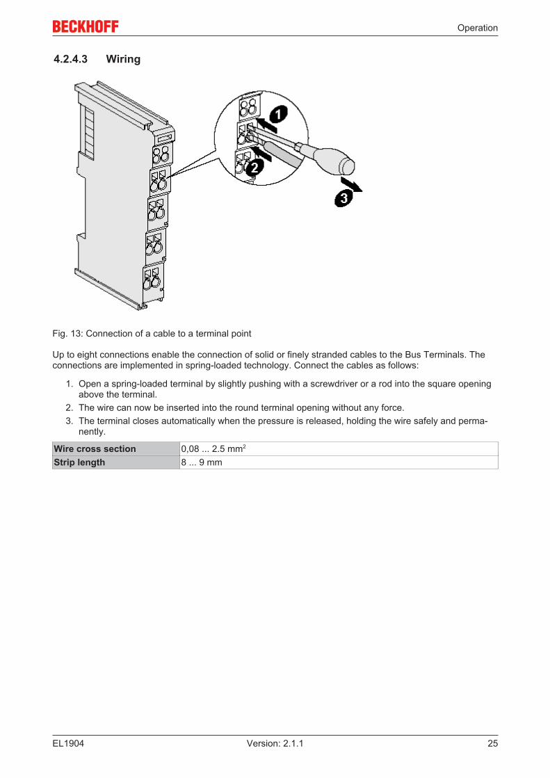
Fig. 13: Connection of a cable to a terminal point
Up to eight connections enable the connection of solid or finely stranded cables to the Bus Terminals. Theconnections are implemented in spring-loaded technology. Connect the cables as follows:
1. Open a spring-loaded terminal by slightly pushing with a screwdriver or a rod into the square openingabove the terminal.
2. The wire can now be inserted into the round terminal opening without any force.3. The terminal closes automatically when the pressure is released, holding the wire safely and perma-
nently.
Wire cross section 0,08 ... 2.5 mm2
Strip length 8 ... 9 mm
Operation
EL190426 Version: 2.1.1
4.2.4.4 EL1904 pin assignment
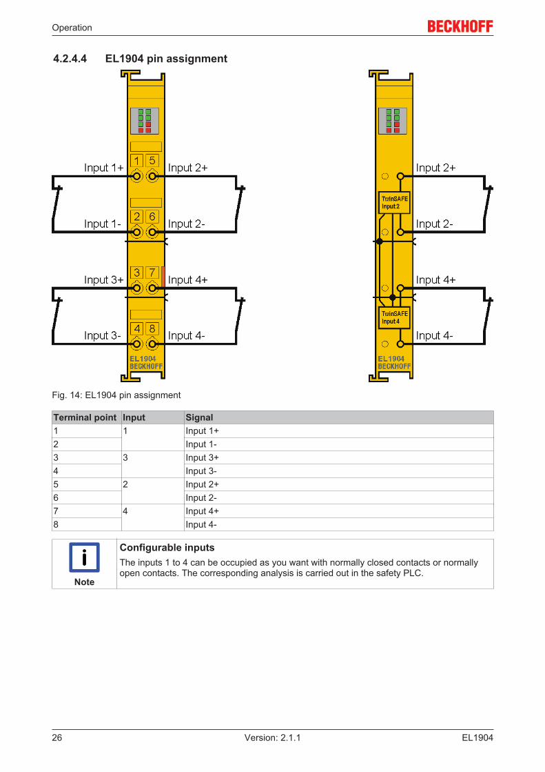
Fig. 14: EL1904 pin assignment
Terminal point Input Signal1 1 Input 1+2 Input 1-3 3 Input 3+4 Input 3-5 2 Input 2+6 Input 2-7 4 Input 4+8 Input 4-
Note
Configurable inputsThe inputs 1 to 4 can be occupied as you want with normally closed contacts or normallyopen contacts. The corresponding analysis is carried out in the safety PLC.

Operation
EL1904 27Version: 2.1.1
4.2.4.5 Signal cables
Permitted cable length
Fig. 15: Permitted cable length
When connecting a single switching contact via its own continuous cabling (or via a non-metallic sheathedcable), the maximum permitted cable length is 100 m.
The use of contact points, connectors or additional switching contacts in the cabling reduces the maximumpropagation.
Cable routing
Fig. 16: Cable routing

Operation
EL190428 Version: 2.1.1
Attention
Route the signal cable separatelyThe signal cable must be routed separately from potential sources of interference, such asmotor supply cables, 230 VAC power cables etc.!Interference caused by cables routed in parallel can influence the signal form of the testpulses and thus cause diagnostic messages (e.g. sensor errors or OpenLoad errors).D: Distance between the cable ducts should be as large as possibleblue arrows: signal linered arrows: potential source of interference
The common routing of signals together with other clocked signals in a common cable also reduces themaximum propagation, since crosstalk of the signals can occur over long cable lengths and cause diagnosticmessages.
The test pulses can be switched off (sensor test parameter) if the connection of a common cable isunavoidable. However, this then leads to a reduction in the degree of diagnostic cover when calculating theperformance level.
Test pulses
The typical length of a test pulse (switching from 24 V to 0 V and back to 24 V) is 350 µs and takes placeapprox. 250 times per second.
The test pulses at the outputs Input 1+ to Input 4+ are generated separately for each channel in order to beable to detect cross-circuits between the individual channels of a terminal and also between channels ofdifferent terminals. In order to generate test pulses as shown in the diagram, the sensor test active safetyparameter must be set to true for the respective channels. The test cycle for all four channels is typically 4ms. The times between the test pulses of different channels vary, thus allowing better diagnostic detection.
Fig. 17: Typical course of test pulses of the inputs
If self-testing sensors are to be used on the safe inputs, please refer to chapter Configuration for lightbarriers, light grids, light curtains etc [} 37].

Operation
EL1904 29Version: 2.1.1
4.2.5 TwinSAFE reaction timesThe TwinSAFE terminals form a modular safety system that exchanges safety-oriented data via the Safety-over-EtherCAT protocol. This chapter is intended to help you determine the system's reaction time from thechange of signal at the sensor to the reaction at the actuator.
Typical reaction time
The typical reaction time is the time that is required to transmit information from the sensor to the actuator, ifthe overall system is working without error in normal operation.
Fig. 18: Typical reaction time
Definition DescriptionRTSensor Reaction time of the sensor until the signal is provided at the interface. Typically supplied by
the sensor manufacturer.RTInput Reaction time of the safe input, such as EL1904 or EP1908. This time can be found in the
technical data. In the case of the EL1904 it is 4 ms.RTComm Reaction time of the communication This is typically 3x the EtherCAT cycle time, because
new data can only be sent in a new Safety-over-EtherCAT telegram. These times dependdirectly on the higher-level standard controller (cycle time of the PLC/NC).
RTLogic Reaction time of the logic terminal. This is the cycle time of the logic terminal and typicallyranges from 500 µs to 10 ms for the EL6900, depending on the size of the safety project.The actual cycle time can be read from the terminal.
RTOutput Reaction time of the output terminal. This typically lies within the range of 2 to 3 ms.RTActor Reaction time of the actuator. This information is typically supplied by the actuator
manufacturerWDComm Watchdog time of the communication
This results in the following equation for the typical reaction time:
with, for example
Worst-case reaction time
The worst case reaction time is the maximum time required to switch off the actuator in the case of an error.

Operation
EL190430 Version: 2.1.1
Fig. 19: Worst-case reaction time
This assumes that a signal change occurs at the sensor and is transmitted to the input. A communicationerror occurs at precisely the moment when the signal is to be transferred to the communication interface.This is detected by the logic following the watchdog time of the communication link. This information shouldthen be transferred to the output, but a further communication error occurs here. This error is detected at theoutput following the expiry of the watchdog time and leads to the switch-off.
This results in the following equation for the worst-case reaction:
with, for example
4.2.6 Tested EL1904 devicesThe following list contains devices that were tested together with the EL1904 TwinSAFE terminal. Theresults only apply for the current device hardware version at the time of testing. The tests were carried out ina laboratory environment. Modifications of these products cannot be considered here. If you are unsureplease test the hardware together with the TwinSAFE terminal.
Manufacturer Type CommentSICK C4000 Safety light curtainSICK S3000 Safety laser scannerWenglor SG2-14ISO45C1 Safety light gridsLeuze lumiflex ROBUST 42/43/44 Safety light barriersSchmersal BNS250-11ZG Safety switchifm GM701S Inductive safety sensorKeyence SL-V (with PNP cable set) Safety light curtain
The tests were carried out as function tests only. The information provided in the respective manufacturerdocumentation remains valid.

Operation
EL1904 31Version: 2.1.1
4.3 Operation in potentially explosive atmospheres (ATEX)
4.3.1 Special conditions
WARNING
Observe the special conditions for the intended use of Beckhoff fieldbuscomponents in potentially explosive areas (directive 94/9/EU)!The certified components are to be installed in a suitable housing that guarantees a protec-tion class of at least IP54 in accordance with EN 60529! The environmental conditions dur-ing use are thereby to be taken into account!If the temperatures during rated operation are higher than 70 °C at the feed-in points of ca-bles, lines or pipes, or higher than 80°C at the wire branching points, then cables must beselected whose temperature data correspond to the actual measured temperature values!Observe the permissible ambient temperature range of 0 to 55 °C when using Beckhofffieldbus components in potentially explosive atmospheres!Measures must be taken to protect against the rated operating voltage being exceeded bymore than 40% due to short-term interference voltages!The individual terminals may only be unplugged or removed from the Bus Terminal systemif the supply voltage has been switched off or if a non-explosive atmosphere is ensured!The connections of the certified components may only be connected or disconnected if thesupply voltage has been switched off or if a non-explosive atmosphere is ensured!The fuses of the EL92xx power feed terminals may only be exchanged if the supply voltagehas been switched off or if a non-explosive atmosphere is ensured!Address selectors and ID switches may only be adjusted if the supply voltage has beenswitched off or if a non-explosive atmosphere is ensured!
The fundamental health and safety requirements are fulfilled by compliance with the following standards:
• EN 60079-0: 2006• EN 60079-15: 2005

Operation
EL190432 Version: 2.1.1
4.3.2 IdentificationBeckhoff fieldbus components that are certified for use in potentially explosive atmospheres bear one of thefollowing markings:
II 3 G Ex nA II T4 KEMA 10ATEX0075 X Ta: 0 - 55°C
or
II 3 G Ex nA nC IIC T4 KEMA 10ATEX0075 X Ta: 0 - 55°C
4.3.3 Date code and serial numberThe TwinSAFE terminals bear a date code, which is composed as follows:
Date code: CW YY SW HW
Legend:CW: Calendar week of manufactureYY: Year of manufactureSW: Software versionHW: Hardware version
Sample: Date code 29 10 02 01Calendar week: 29Year: 2010Software version: 02Hardware version: 01
In addition the TwinSAFE terminals bear a unique serial number.
4.3.4 Further ATEX documentation
Note
Please also refer to the further documentationNotes regarding application of the Bus Terminal system in areas potentially explosive at-mosphere are available in the Download section of the Beckhoff website at http://www.beckhoff.de.
4.4 Configuration of the terminal in TwinCAT
CAUTION
Do not change CoE objects!Do not change any of the CoE objects in the TwinSAFE terminals. Any modifications (e.g.via TwinCAT) of the CoE objects will permanently set the terminals to the Fail-Stop state orlead to unexpected behavior of the terminals!
4.4.1 Inserting a Bus CouplerSee TwinCAT automation software documentation.

Operation
EL1904 33Version: 2.1.1
4.4.2 Inserting a Bus TerminalSee TwinCAT automation software documentation.
4.4.3 Inserting an EL1904An EL1904 is inserted in the same way as any other Beckhoff Bus Terminal. In the list open SafetyTerminals (ELx9xx) and select the EL1904.
Fig. 20: Inserting an EL1904

Operation
EL190434 Version: 2.1.1
4.4.4 Address settings on TwinSAFE terminals with 65535 possibleaddresses
Fig. 21: Address settings on TwinSAFE terminals with 65535 possible addresses
Set the TwinSAFE address for the terminal using the two dip switches (with 8 setting options) on the left-hand side of the EL1904 TwinSAFE terminal. TwinSAFE addresses between 1 and 65535 are available.
DIP switches Ad-dress
1 2 3 4 5 6 7 8 9 10 11 12 13 14 15 16ON OFF OFF OFF OFF OFF OFF OFF OFF OFF OFF OFF OFF OFF OFF OFF 1OFF ON OFF OFF OFF OFF OFF OFF OFF OFF OFF OFF OFF OFF OFF OFF 2ON ON OFF OFF OFF OFF OFF OFF OFF OFF OFF OFF OFF OFF OFF OFF 3OFF OFF ON OFF OFF OFF OFF OFF OFF OFF OFF OFF OFF OFF OFF OFF 4ON OFF ON OFF OFF OFF OFF OFF OFF OFF OFF OFF OFF OFF OFF OFF 5OFF ON ON OFF OFF OFF OFF OFF OFF OFF OFF OFF OFF OFF OFF OFF 6ON ON ON OFF OFF OFF OFF OFF OFF OFF OFF OFF OFF OFF OFF OFF 7OFF OFF OFF ON OFF OFF OFF OFF OFF OFF OFF OFF OFF OFF OFF OFF 8… … … … … … … … … … … … … … … … …ON ON ON ON ON ON ON ON ON ON ON ON ON ON ON ON 65535
WARNING
TwinSAFE addressEach TwinSAFE address may only be used once within a network!The address 0 is not a valid TwinSAFE address!

Operation
EL1904 35Version: 2.1.1
4.4.5 Entering a TwinSAFE address and parameters in the SystemManager
The TwinSAFE address set at the DIP switch must also be entered in tab FSoE (under FSoE address) underthe EL1904.
Fig. 22: Entering the FSoE address
The EL1904 parameters are set under the respective TwinSAFE connection in the Connection andParameter tabs.

Operation
EL190436 Version: 2.1.1
Fig. 23: Setting the connection of the TwinSAFE connection
Fig. 24: Setting the parameters of the TwinSAFE connection

Operation
EL1904 37Version: 2.1.1
Parameter overview
PrmName Meaning ValuesFSoE_Address DIP switch address 1 to 65535Operating Mode Digital / standstill monitoring 1 and 2 Digital / standstill 1 and 2Sensor testchannel 1 active
The clock signal for connection Input1+is checked at connection Input1-.
true / false
Sensor testchannel 2 active
The clock signal for connection Input2+is checked at connection Input2-.
true / false
Sensor testchannel 3 active
The clock signal for connection Input3+is checked at connection Input3-.
true / false
Sensor testchannel 4 active
The clock signal for connection Input4+is checked at connection Input4-.
true / false
Logic channel 1and 2
Logic of channels 1 and 2 • single logic• asynchronous repetition OSSD (sensor
test must be switched off)• any pulse repetition OSSD (sensor test
must be switched off)• short cut is no module fault
Logic channel 3and 4
Logic of channels 3 and 4 • single logic• asynchronous repetition OSSD (sensor
test must be switched off)• any pulse repetition OSSD (sensor test
must be switched off)• short cut is no module fault
Store Code This parameter is required for theTwinSAFE Restore Mode
0x0000
Project CRC This parameter is required for theTwinSAFE Restore Mode
0x0000
4.4.5.1 EL1904 configuration for light barriers, light grids, light curtains etc.
The EL1904 also supports direct connection of contact-free protective devices with two self-testing outputssuch as light barriers, light grids, light curtains, laser scanners, etc.
CAUTION
Sensors with self-testing outputs!Only sensors with self-testing outputs and a maximum sensor self-test duration of 350 µsmay be connected to the EL1904 (see illustration below).

Operation
EL190438 Version: 2.1.1
Fig. 25: Maximum permissible sensor self-test duration of 350 µs
Parameter
To connect these sensors please set the following parameters for the EL1904 in the TwinCAT SystemManager:
Connect the two sensor signals either to channels 1 and 2 or channels 3 and 4 and activate asynchronousrepetition OSSD or any pulse repetition for the two inputs used under parameter Logic for channel x and y.The difference between these settings is that with any pulse repetition simultaneous tests of the OSSDsignals up to 350 µs are allowed.
For the two inputs used set the sensor test for the EL1904 to false.
4.4.5.2 Configuration of the EL1904 for safety switching mats
The EL1904 also supports direct connection of safety switching mats.
Parameter
To connect these switching mats please set the following parameters for the EL1904 in the TwinCAT SystemManager:
Connect the two sensor signals either to channels 1 and 2 or channels 3 and 4 and activate short cutchannel x/y is no module fault for the two inputs used under parameter Logic for channel x and y.

Operation
EL1904 39Version: 2.1.1
4.5 Diagnostics
4.5.1 Diagnostic LEDsThe LEDs Diag 1 to Diag 4 display diagnostic information for the EL1904.
4.5.1.1 Diag 1 (green)
The Diag 1 LED indicates the state of the TwinSAFE interface.
Flashing Code MeaningLED illuminated continuously normal operation:
TwinSAFE communication OKrapid flickering, alternating with 1 flash pulse Error in S parameter (TwinSAFE parameter)rapid flickering, alternating with 2 flash pulses Error in I parameter (Individual parameter)rapid flickering, alternating with 3 flash pulses Waiting for S and I parameterrapid flickering, alternating with 4 flash pulses S- and I-parameter correct:
waiting for first host messagerapid flickering, alternating with 5 flash pulses Watchdog errorrapid flickering, alternating with 6 flash pulses CRC errorrapid flickering, alternating with 7 flash pulses Sequence number errorrapid flickering, alternating with 8 flash pulses Communication error in the TwinSAFE protocol
4.5.1.2 Diag 2 (red)
The Diag 2 LED illuminates red if the terminal detects an external supply or cross-circuit. The LEDextinguishes once the error is rectified.
4.5.1.3 Diag 3 (red) and Diag 4 (red)
If the Diag 3 LED is lit, the Diag 4 LED indicates internal terminal errors.
Flashing Codes
In the case of such an error, the Diag 4 LED on the EL1904 displays flashing codes that describe the error inmore detail.
A flashing code consists of four sequences, which are interrupted in each case by a short break. After thefour sequences there is a long break, following which the flashing code is displayed again.
Count the individual sequences of the flashing code.

Operation
EL190440 Version: 2.1.1
The errors indicated by the following flashing codes are reversible. After successful troubleshooting theterminal can be restarted.
Diag 3 LED Diag 4 LEDFlashingCode
Meaning Remedy
lit 6-1-1-1 max. internal temperatureexceeded
Ensure that the permissible ambienttemperature is adhered to.
7-1-1-1 internal temperature below min.value
2-1-2-1 max. supply voltage µC1exceeded
Check the supply voltage.
3-1-2-1 max. supply voltage µC2exceeded
4-1-2-1 voltage fell below min. supplyvoltage µC1
5-1-2-1 voltage fell below min. supplyvoltage µC2
8-1-1-1 Temperature difference betweenthe measuring points exceeded
Check the installation position and theambient temperature.
If another flashing code is displayed, this means that there is an internal terminal error that has stopped theterminal. In this case the terminal must be checked by Beckhoff Automation GmbH & Co. KG.
Note
Note the flashing codes and return the terminalNote the flashing code displayed and include this information with the terminal when youreturn it.
4.5.2 Diagnostic objects
CAUTION
Do not change CoE objects!Do not make any modifications to the CoE objects in the TwinSAFE components! Any mod-ifications (e.g. using TwinCAT) of the CoE objects will permanently set the TwinSAFE com-ponents to the Fail-Stop state.
Index FA80hex: Internal temperature values
The CoE object FA80hex indicates the current internal temperature values of the EL1904.
Index Name Meaning Flags DefaultFA80:01 Temperature 1 Temperature measurement 1 RO 0bin
FA80:02 Temperature 2 Temperature measurement 2 RO 0bin
Index 800Ehex: diagnostic information
The CoE object 800Ehex displays further diagnostic information.

Operation
EL1904 41Version: 2.1.1
Index Name Meaning Flags Default800E:0 Diag The following sub-indices contain detailed diagnostic
information.RO
800E:0A Sensor test error Bit Error during the sensor test RO0 1bin Error at input 1 0bin
1 1bin Error at input 2 0bin
2 1bin Error at input 3 0bin
3 1bin Error at input 4 0bin
800E:0B Error during two-channelevaluation
Bit Error during the contiguous evaluation of two channels,i.e. the two channels contradict each other.
RO
0 1bin Error in the first input pair 0bin
1 1bin Error in the second input pair 0bin
800E:0C Error in the safetymat operation mode:input pair disagree
Bits Error in the input pair RO1, 0 11bin Error in the first input pair 00bin
3, 2 11bin Error in the second input pair 00bin
800E:0D Error in the safetymat operation mode:external supply
Bit Error in the test pulses in the safety mat operatingmode; i.e. the terminal has detected an externalsupply.
RO
0 1bin Error at input 1 0bin
1 1bin Error at input 2 0bin
2 1bin Error at input 3 0bin
3 1bin Error at input 4 0bin
Note
Differing diagnostic messages possibleDue to the variable order or execution of the test series, diagnostic messages differing fromthose given in the table above are possible.
4.6 Maintenance
Maintenance
The TwinSAFE components are maintenance-free!
Environmental conditions
WARNING
Observe the specified environmental conditions!Please ensure that the TwinSAFE components are only stored and operated under thespecified conditions (see technical data).
If the TwinSAFE component is operated outside the permitted temperature range it will switch to GlobalShutdown state.
Cleaning
Protect the TwinSAFE component from unacceptable soling during operation and storage!
If the TwinSAFE component was subjected to unacceptable soiling it may no longer be operated!
WARNING
Have soiled terminals checked!Cleaning of the TwinSAFE component by the user is not permitted!Please send soiled terminals to the manufacturer for inspection and cleaning!
Operation
EL190442 Version: 2.1.1
4.7 Service lifeThe TwinSAFE terminals are designed for a service life of 20 years.
Due to the high diagnostic coverage within the lifecycle no special proof tests are required.
The TwinSAFE terminals bear a date code, which is composed as follows:
Date code: CW YY SW HW
Legend:CW: Calendar week of manufactureYY: Year of manufactureSW: Software versionHW: Hardware version
Sample: Date Code 17 11 05 00Calendar week: 17Year: 2011Software version: 05Hardware version: 00
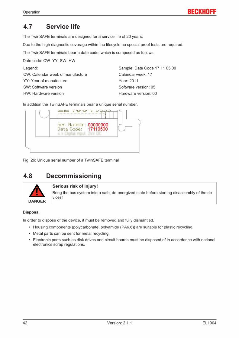
In addition the TwinSAFE terminals bear a unique serial number.
Fig. 26: Unique serial number of a TwinSAFE terminal
4.8 Decommissioning
DANGER
Serious risk of injury!Bring the bus system into a safe, de-energized state before starting disassembly of the de-vices!
Disposal
In order to dispose of the device, it must be removed and fully dismantled.
• Housing components (polycarbonate, polyamide (PA6.6)) are suitable for plastic recycling.• Metal parts can be sent for metal recycling.• Electronic parts such as disk drives and circuit boards must be disposed of in accordance with national
electronics scrap regulations.

Appendix
EL1904 43Version: 2.1.1
5 Appendix
5.1 Support and ServiceBeckhoff and their partners around the world offer comprehensive support and service, making available fastand competent assistance with all questions related to Beckhoff products and system solutions.
Beckhoff's branch offices and representatives
Please contact your Beckhoff branch office or representative for local support and service on Beckhoffproducts!
The addresses of Beckhoff's branch offices and representatives round the world can be found on her internetpages:http://www.beckhoff.com
You will also find further documentation for Beckhoff components there.
Beckhoff Headquarters
Beckhoff Automation GmbH & Co. KG
Huelshorstweg 2033415 VerlGermany
Phone: +49(0)5246/963-0Fax: +49(0)5246/963-198e-mail: [email protected]
Beckhoff Support
Support offers you comprehensive technical assistance, helping you not only with the application ofindividual Beckhoff products, but also with other, wide-ranging services:
• support• design, programming and commissioning of complex automation systems• and extensive training program for Beckhoff system components
Hotline: +49(0)5246/963-157Fax: +49(0)5246/963-9157e-mail: [email protected]
Beckhoff Service
The Beckhoff Service Center supports you in all matters of after-sales service:
• on-site service• repair service• spare parts service• hotline service
Hotline: +49(0)5246/963-460Fax: +49(0)5246/963-479e-mail: [email protected]

Appendix
EL190444 Version: 2.1.1
5.2 Certificates

Appendix
EL1904 45Version: 2.1.1
Table of figures
EL190446 Version: 2.1.1
Table of figuresFig. 1 Slot and key system and screwless (spring-loaded) connection system..................................... 9Fig. 2 Bus Coupler (EtherCAT).............................................................................................................. 10Fig. 3 TwinSAFE Terminals (EtherCAT)................................................................................................ 11Fig. 4 EL1904 – TwinSAFE terminal with 4 digital fail-safe inputs......................................................... 14Fig. 5 Characteristic curve of the inputs ................................................................................................ 17Fig. 6 Dimensions of the EL1904........................................................................................................... 18Fig. 7 Block diagram of the EL1904....................................................................................................... 18Fig. 8 Installation position and minimum distances ............................................................................... 20Fig. 9 Example configuration for temperature measurement................................................................. 21Fig. 10 Installation on the mounting rail ................................................................................................... 22Fig. 11 Removal of mounting rails ........................................................................................................... 23Fig. 12 PE power contact......................................................................................................................... 24Fig. 13 Connection of a cable to a terminal point .................................................................................... 25Fig. 14 EL1904 pin assignment ............................................................................................................... 26Fig. 15 Permitted cable length ................................................................................................................. 27Fig. 16 Cable routing ............................................................................................................................... 27Fig. 17 Typical course of test pulses of the inputs................................................................................... 28Fig. 18 Typical reaction time.................................................................................................................... 29Fig. 19 Worst-case reaction time ............................................................................................................. 30Fig. 20 Inserting an EL1904..................................................................................................................... 33Fig. 21 Address settings on TwinSAFE terminals with 65535 possible addresses ................................. 34Fig. 22 Entering the FSoE address.......................................................................................................... 35Fig. 23 Setting the connection of the TwinSAFE connection................................................................... 36Fig. 24 Setting the parameters of the TwinSAFE connection .................................................................. 36Fig. 25 Maximum permissible sensor self-test duration of 350 µs........................................................... 38Fig. 26 Unique serial number of a TwinSAFE terminal............................................................................ 42