Operating Instructions - eww.pass.panasonic.co.jp · Operating Instructions Live Switcher Model No....
196
Operating Instructions Live Switcher Model No. AV-UHS500P Model No. AV-UHS500E ENGLISH DVQP2118YA W0220GU1060 -FJ Before operating this product, please read the instructions carefully and save this manual for future use. Please carefully read the “Read this first!” (pages 3 to 7) of this Manual before use.
Transcript of Operating Instructions - eww.pass.panasonic.co.jp · Operating Instructions Live Switcher Model No....

Operating InstructionsLive Switcher
Model No. AV-UHS500PModel No. AV-UHS500E
ENGLISHDVQP2118YAW0220GU1060 -FJ
Before operating this product, please read the instructions carefully and save this manual for future use.Please carefully read the “Read this first!” (pages 3 to 7) of this Manual before use.
2
pp Information on software for this product1. Included with this product is software licensed under the GNU General Public License (GPL) and GNU Lesser General
Public License (LGPL), and users are hereby informed that they have the right to obtain, change and redistribute the source codes of this software.
To obtain the source codes, go to the following website:
https://pro-av.panasonic.net/
The manufacturer asks users to refrain from directing inquiries concerning the source codes they have obtained and other details to its representatives.
2. Included with this product is software which is licensed under MIT-License.3. This product includes software which is licensed under FreeType Project (www.freetype.org).
For more information about these, refer to the website below.https://pro-av.panasonic.net/manual/en/index.htmlDetails are given in the original (English language) text.
Trademarks and registered trademarks
pp The terms HDMI and HDMI High-Definition Multimedia Interface, and the HDMI Logo are trademarks or registered trademarks of HDMI Licensing Administrator, Inc. in the United States and other countries.pp SDXC Logo is a trademark of SD-3C, LLC.pp Primatte® is the registered trademark of Photron Limited.pp Photron Limited is the holder of the intellectual rights to
Primatte®.pp Photron Limited is the holder of the patent for Primatte®.pp Other names of companies and products contained
in these Operating Instructions may be trademarks or registered trademarks of their respective owners.
About copyright and licence
Distributing, copying, disassembling, reverse compiling, reverse engineering, and also exporting in violation of export laws of the software provided with this unit are expressly prohibited.
Abbreviations
The following abbreviations are used in this manual.
pp Both SDHC memory cards and SDXC memory cards are described as “memory cards” in this manual. When individual descriptions are provided, they are featured individually.pp Personal computers are referred to as “computers”.
Furthermore, the product numbers of equipment are referred to as follows.
Model number of unitModel number given in
manual
AV-UHS500P AV-UHS500
AV-UHS500E AV-UHS500
AV-UHS5M1G AV-UHS5M1
AV-UHS5M2G AV-UHS5M2
AV-UHS5M3G AV-UHS5M3
AV-UHS5M4G AV-UHS5M4
AV-UHS5M5G AV-UHS5M5
Illustrations and screen displays featured in the manual
pp What is shown in the manual’s illustrations and screen displays may differ from how it is actually appears.
3
Read this first!
indicates safety information.
WARNING:Always keep memory cards (optional accessory) or accessory (mounting screws) out of the reach of babies and small children.
WARNING:This equipment is compliant with Class A of CISPR 32.In a residential environment this equipment may cause radio interference.
CAUTION:A coin type battery is installed inside of the unit.Do not expose the unit to excessive heat such as sunshine, fire or the like.
CAUTION:To reduce the risk of fire or electric shock, refer mounting of the optional interface boards to qualified service personnel.
WARNING:• To reduce the risk of fire or electric shock, do not
expose this equipment to rain or moisture.• To reduce the risk of fire or electric shock, keep
this equipment away from all liquids. Use and store only in locations which are not exposed to the risk of dripping or splashing liquids, and do not place any liquid containers on top of the equipment.
CAUTION:To reduce the risk of fire or electric shock and annoying interference, use the recommended accessories only.
CAUTION:In order to maintain adequate ventilation, do not install or place this unit in a bookcase, built-in cabinet or any other confined space. To prevent risk of electric shock or fire hazard due to overheating, ensure that curtains and any other materials do not obstruct the ventilation.
CAUTION:The mains plug of the power supply cord shall remain readily operable.The AC receptacle (mains socket outlet) shall be installed near the equipment and shall be easily accessible. To completely disconnect this equipment from the AC mains, disconnect the power cord plug from the AC receptacle.
WARNING:This equipment must be grounded.To ensure safe operation, the three-pin plug must be inserted only into a standard three-pin power outlet which is effectively grounded through normal household wiring.Extension cords used with the equipment must have three cores and be correctly wired to provide connection to the ground. Wrongly wired extension cords are a major cause of fatalities.The fact that the equipment operates satisfactorily does not imply that the power outlet is grounded or that the installation is completely safe. For your safety, if you are in any doubt about the effective grounding of the power outlet, please consult a qualified electrician.
CAUTION:This apparatus can be operated at a voltage in the range of 100 – 240 V AC.Voltages other than 120 V are not intended for U.S.A. and Canada.Operation at a voltage other than 120 V AC may require the use of a different AC plug. Please contact either a local or foreign Panasonic authorized service center for assistance in selecting an alternate AC plug.
CAUTION:Do not remove panel covers by unscrewing.To reduce the risk of electric shock, do not remove the covers. No user serviceable parts inside.Refer servicing to qualified service personnel.
CAUTION:Naked flame sources, such as lighted candles, should not be placed on the apparatus.
For U.S.A. and Canada

4
The symbols on this product (including the accessories) represent the following:
AC
Read this first!
FCC NOTICE (USA)
Supplier’s Declaration of ConformityModel Number: AV-UHS500PTrade Name: PanasonicResponsible Party: Panasonic Corporation of North AmericaTwo Riverfront Plaza, Newark, NJ 07102Support contact: 1-800-524-1448
This device complies with part 15 of the FCC Rules.Operation is subject to the following two conditions:(1) This device may not cause harmful interference, and (2) this device must accept any interference received, including interference that may cause undesired operation.
FCC Note:This equipment has been tested and found to comply with the limits for a class A digital device, pursuant to Part 15 of the FCC Rules. These limits are designed to provide reasonable protection against harmful interference when the equipment is operated in a commercial environment. This equipment generates, uses, and can radiate radio frequency energy, and if not installed and used in accordance with the instruction manual, may cause harmful interference to radio communications. Operation of this equipment in a residential area is likely to cause harmful interference in which case the user will be required to correct the interference at his own expense.
Warning:To assure continued FCC emission limit compliance, the user must use only shielded interface cables when connecting to external units. Also, any unauthorized changes or modifications to this equipment could void the user’s authority to operate it.
NOTIFICATION (Canada)
CAN ICES-3 (A)/NMB-3(A)
For AV-UHS500P
indicates safety information.

5
Read this first!
For AV-UHS500E
Caution for AC Mains LeadFOR YOUR SAFETY PLEASE READ THE FOLLOWING TEXT CAREFULLY.This product is equipped with 3 types of AC mains cable.
Appropriate mains cable must be used in each local area, since the other type of mains cable is not suitable.
FOR CONTINENTAL EUROPE, ETC.Not to be used in the U.K.
FOR U.K. ONLYIf the plug supplied is not suitable for your socket outlet, it should be cut off and appropriate one fitted.
FOR INDIA ONLY
FOR U.K. ONLY
This appliance is supplied with a moulded three pin mains plug for your safety and convenience.A 13 amp fuse is fitted in this plug.Should the fuse need to be replaced please ensure that the replacement fuse has a rating of 13 amps and that it is approved by ASTA or BSI to BS1362.Check for the ASTA mark or the BSI mark on the body of the fuse.
If the plug contains a removable fuse cover you must ensure that it is refitted when the fuse is replaced.If you lose the fuse cover the plug must not be used until a replacement cover is obtained.A replacement fuse cover can be purchased from your local Panasonic Dealer.
How to replace the fuse1. Open the fuse compartment with a screwdriver.
2. Replace the fuse.
Fuse
indicates safety information.
Manufactured by: Panasonic Corporation, Osaka, JapanImporter’s name and address of pursuant to EU rules: Panasonic Marketing Europe GmbH Panasonic Testing Centre Winsbergring 15, 22525 Hamburg, Germany

6
Read this first!
EMC NOTICE FOR THE PURCHASER/USER OF THE APPARATUS
1. Pre-requisite conditions to achieving compliance with the above standards
<1> Peripheral equipment to be connected to the apparatus and special connecting cables • The purchaser/user is urged to use only equipment which has been recommended by us as peripheral equipment to
be connected to the apparatus. • The purchaser/user is urged to use only the connecting cables described below.
<2> For the connecting cables, use shielded cables which suit the intended purpose of the apparatus. • Video signal connecting cables
Use double shielded coaxial cables, which are designed for 75-ohm type high-frequency applications, for SDI (Serial Digital Interface). Coaxial cables, which are designed for 75-ohm type high-frequency applications, are recommended for analog video signals.
• Audio signal connecting cables If your apparatus supports AES/EBU serial digital audio signals, use cables designed for AES/EBU. Use shielded cables, which provide quality performance for high-frequency transmission applications, for analog audio signals.
• Other connecting cables (LAN, RS-422) Use shielded cables, which provide quality performance for high-frequency applications, as connecting cables.
• When connecting to the DVI signal terminal, use a cable with a ferrite core. • If your apparatus is supplied with ferrite core(s), they must be attached on cable(s) following instructions in this
manual.
2. Performance level The performance level of the apparatus is equivalent to or better than the performance level required by these standards.
However, the apparatus may be adversely affected by interference if it is being used in an EMC environment, such as an area where strong electromagnetic fields are generated (by the presence of signal transmission towers, cellular phones, etc.). In order to minimize the adverse effects of the interference on the apparatus in cases like this, it is recommended that the following steps be taken with the apparatus being affected and with its operating environment:
1. Place the apparatus at a distance from the source of the interference. 2. Change the direction of the apparatus. 3. Change the connection method used for the apparatus. 4. Connect the apparatus to another power outlet where the power is not shared by any other appliances.
EU
Disposal of Old Equipment and BatteriesOnly for European Union and countries with recycling systemsThese symbols on the products, packaging, and/or accompanying documents mean that used electrical and electronic products and batteries must not be mixed with general household waste.For proper treatment, recovery and recycling of old products and used batteries, please take them to applicable collection points in accordance with your national legislation.By disposing of them correctly, you will help to save valuable resources and prevent any potential negative effects on human health and the environment.For more information about collection and recycling, please contact your local authority, dealer or supplier.Penalties may be applicable for incorrect disposal of this waste, in accordance with national legislation
Note for the battery symbol (bottom symbol):This symbol might be used in combination with a chemical symbol. In this case it complies with the requirement set by the Directive for the chemical involved.
Turkey OnlyAEEE Yönetmeliğine Uygundur.AEEE Complies with Directive of Turkey.
TO REMOVE BATTERYBack-up Battery (Lithium Battery)• For the removal of the battery for disposal at the end of its service life, please consult your dealer.
7
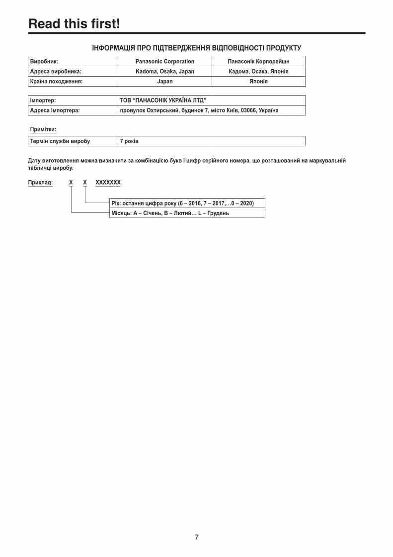
ІНФОРМАЦІЯ ПРО ПІДТВЕРДЖЕННЯ ВІДПОВІДНОСТІ ПРОДУКТУВиробник: Panasonic Corporation Панасонік КорпорейшнАдреса виробника: Kadoma, Osaka, Japan Кадома, Осака, ЯпоніяКраїна походження: Japan Японія
Імпортер: ТОВ “ПАНАСОНІК УКРАЇНА ЛТД”Адреса Імпортера: провулок Охтирський, будинок 7, місто Київ, 03066, Україна
Примітки:
Термін служби виробу 7 років
Дату виготовлення можна визначити за комбінацією букв і цифр серійного номера, що розташований на маркувальній табличці виробу.
Приклад: X X XXXXXXX
Рік: остання цифра року (6 – 2016, 7 – 2017,…0 – 2020)Місяць: А – Січень, В – Лютий… L – Грудень
Read this first!

8
Contents
Read this first! ............................................. 3
Before use .................................................. 11Overview ......................................................................... 11
Concerning the ratings display .................................... 11
Disclaimer of warranty .................................................. 11
Network security ............................................................ 11
Precautions for use ................................... 12
Installation precautions ............................ 13
Features ...................................................... 14
Accessories ............................................... 15
Installation and connections .................... 15How to install the optional units ................................... 15
Parts and their functions .......................... 17
Control panel ................................................................... 17
Crosspoint area .............................................................. 18
Memory/wipe pattern/number key area .......................... 19
User button area ............................................................. 20
Transition area ................................................................ 20
Display area ................................................................... 22
Positioner area ............................................................... 24
Memory card area .......................................................... 25
Rear panel area ............................................................... 26
Preparations ............................................... 27
Turning the unit’s power on and off .............................. 27
Basic menu operations ................................................... 28
Menu configuration and operations ................................ 28
Keyboard screen operations ........................................... 30
Menu delegation function ............................................... 30
Setting the system format ............................................... 31
Setting the date and time ............................................... 31
Basic operations ........................................ 32
Background transition .................................................... 32
Selecting the bus ............................................................ 32
Selecting the bus using the SHIFT function ................... 32
Selecting the bus mode .................................................. 33
Selecting the transition mode ......................................... 33
Manual transition ............................................................ 34
Auto transition ................................................................ 34
Cut transition .................................................................. 34
Wipe .................................................................................. 35
Selecting the wipe pattern .............................................. 35
Selecting the wipe direction............................................ 36
Wipe decorations (border, soft effect) ............................ 36
Setting the wipe start position ........................................ 37
Modifying wipe................................................................ 37
Setting the latency .......................................................... 38
Creating an animated wipe............................................. 39
Key .................................................................................... 39
Selecting the key type .................................................... 40
Selecting the key material .............................................. 41
Key transitions ................................................................ 42
Key preview .................................................................... 44
Adjusting the luminance key and linear key ................... 45
Adjusting the chroma key ............................................... 45
Key decorations .............................................................. 49
Masking the key signals ................................................. 50
Flying key ....................................................................... 50
Setting the priority .......................................................... 51
PinP (picture in picture) .................................................. 52
Selecting the PinP channel and material ....................... 52
Selecting Shape ............................................................. 52
PinP adjustments ........................................................... 53
Linking Key PinP and DSK PinP .................................... 53
PinP decorations ............................................................ 54
Trimming settings ........................................................... 55
DSK (downstream key) ................................................... 56
Selecting the DSK type .................................................. 56
Selecting the DSK material ............................................ 57
DSK transitions ............................................................... 58
DSK preview ................................................................... 59
DSK adjustments............................................................ 59
Masking the DSK signals ............................................... 60
Key Link ........................................................................... 61
FTB (Fade to Black)......................................................... 61
Internal color signals ...................................................... 62
Setting the color background .......................................... 62
Setting the Wash effect................................................... 63
Internal color bar signal ................................................. 63
Test tone settings ........................................................... 63
Switching the AUX output .............................................. 64
Selecting the AUX output materials ................................ 64
AUX1/2 transitions .......................................................... 64
Setting enable/disable for the AUX1/2 transition ............ 65
Memory ............................................................................ 66
Memory registration ....................................................... 67
Memory recall items ....................................................... 67
Storing the settings in the memory (Store) ..................... 68
Recalling the operations stored in the memory (Recall) ...................................................................... 69
Deleting the operations stored in the memory (Delete) ...................................................................... 70
Selecting the buses whose settings are to be registered and or played back ..................................................... 71

9
Contents
Setting effect dissolve (shot memory) ............................ 72
Editing event memory timelines ..................................... 73
Macro memory settings .................................................. 78
Registering memories (Register) ................................... 81
Video memories .............................................................. 82
Recording still images (Still) ........................................... 83
Recording moving images (Clip) .................................... 84
Saving to the internal storage......................................... 85
Playing back moving images (Clip) ................................ 86
Memory card .................................................................... 89
Formatting memory cards .............................................. 91
Saving data on memory cards ....................................... 91
Loading data from memory cards .................................. 92
Deleting files on memory cards ...................................... 93
Displaying the memory card information ........................ 94
Waveform monitor settings ............................................ 95
Input/output signal settings ..................... 96
Input signal settings ....................................................... 96
Settings for the exclusionary input connectors ............... 98
Settings for the color range for input signals .................. 98
Checking the input signal status ..................................... 99
Setting the frame synchronizer ....................................... 99
Setting the delay amount .............................................. 100
Freezing the input signals ............................................ 100
Setting the material names .......................................... 101
Setting the up-converter ............................................... 101
Color Corrector ............................................................. 102
Setting the HDMI input signals ..................................... 105
Displaying the HDMI input signal information ............... 106
Output signal settings .................................................. 107
Assigning the output signals......................................... 108
Setting the SDI output color range ............................... 108
Setting the HDMI output signals ................................... 109
Setting the down-converter (optional) .......................... 110
Setting the sync signals ............................................... 111
Adjusting the output signal phase .............................. 111
Setting the multi view display ...................................... 115
Setting the screen layout .............................................. 115
Setting the split frame and characters .......................... 116
Setting the tally displays ............................................... 116
Changing the material names ...................................... 117
Setting the level meters ................................................ 117
Setting the input signal marks ...................................... 118
Setting the markers ...................................................... 118
Ancillary settings for the AUX bus, PGM, and PVW ... 119
System settings ....................................... 120
Setting the system format ............................................ 120
Switcher mode settings ................................................ 120
Dynamic range and color range settings ...................... 120
Setting the crosspoints ................................................ 121
Assigning signals to the crosspoints ............................ 121
Setting the crosspoint switching ................................... 122
Button assignments ...................................................... 123
Setting the user buttons ............................................... 123
Setting the date and time ............................................. 124
Network settings ........................................................... 124
Setting the built-in display backlight and button illumination ............................................................... 125
Status displays .............................................................. 126
Alarm status displays ................................................... 126
Alarm message ............................................................ 126
Displaying information about the version and optional units ......................................................................... 127
Initialization ................................................................... 128
Initializing setting data .................................................. 128
Initializing fader ............................................................ 128
Remote camera link functions ............... 129
Settings for connections to remote cameras ............. 130
Selecting the terminals for remote camera connection .............................................................. 130
IP address settings ....................................................... 130
Remote camera port settings ....................................... 131
Remote camera authentication settings ....................... 131
Checking the remote camera connection status .......... 131
Remote camera operation direction settings ................ 132
Remote camera tally control settings ........................... 132
Selecting the cameras to be operated .......................... 133
Controlling in the camera control screen ...................... 134
Remote camera settings .............................................. 135
Selecting the remote camera, checking information, and controlling power ...................................................... 135
Remote camera control speed settings ........................ 136
Remote camera on-screen menu and color bar settings .................................................................... 136
Remote camera lens control settings ........................... 137
Remote camera image adjustment settings ................. 137
Remote camera preset memory playback settings ...... 138
Disabling remote camera control .................................. 138
Controlling in the camera preset memory screen ........ 139
Storing preset memories .............................................. 141
Recalling preset memories ........................................... 141
Deleting preset memories ............................................ 141
Selecting a page of preset memories ........................... 142

10
Contents
External interfaces .................................. 143
Setting the GPI I/O ......................................................... 143
LAN ................................................................................. 146
Controlling with external panels .................................. 147
Preparations ................................................................. 147
External panel settings ................................................. 147
Settings on this unit when external panels are connected ................................................................. 147
List of bus IDs and source IDs ..................................... 148
External Control ........................................................... 152
Macro Trigger ............................................................... 153
Appearance .............................................. 154
Specifications .......................................... 155
Setting menu table .................................. 157
Appendix (glossary) ................................ 189
Index ......................................................... 192

11
Before use
pwOverviewThis unit is a 1 ME digital video switcher which supports a multiple number of 4K, 3G and HD formats.The 12G-SDI-compatible AV-UHS500 4K live switcher has basic functions that rival those in larger high-end switchers, making available to you the same operability you would use for producing HD video when you produce 4K video. With its excellent portability, the all-in-one main unit can easily be transported for use at a variety of live music, sport, and entertainment events.Furthermore, along with compatibility with multiple formats (4K, 3G, and HD), the addition of optional units makes it possible to expand to a maximum of 16 SDI inputs, enabling smooth operation even at events with a large number of cameras.The keyers, which enable a variety of program production techniques, are equipped with a total of five keyers including two channels for chroma keys and two channels of PinP.Furthermore, you are able to flexibly select video output to match your purposes, even when you have scenes using different formats, using features such as the up/down converters, HDR/SDR converters, and the ITU-R BT.2020/BT.709 converters.We have endeavored to make the product useful in a variety of portable applications, such as special event venues, broadcast vehicles, at university or company presentations, etc., and of course inside broadcasters themselves. This 4K live switcher really exhibits its high performance capabilities when it produces living images on location.
pwConcerning the ratings displayThe name, model number, and power rating for the unit are displayed on the rear panel.
pwDisclaimer of warrantyIN NO EVENT SHALL Panasonic Corporation BE LIABLE TO ANY PARTY OR ANY PERSON, EXCEPT FOR REPLACEMENT OR REASONABLE MAINTENANCE OF THE PRODUCT, FOR THE CASES, INCLUDING BUT NOT LIMITED TO BELOW:
1 ANY DAMAGE AND LOSS, INCLUDING WITHOUT LIMITATION, DIRECT OR INDIRECT, SPECIAL, CONSEQUENTIAL OR EXEMPLARY, ARISING OUT OF OR RELATING TO THE PRODUCT;
2 PERSONAL INJURY OR ANY DAMAGE CAUSED BY INAPPROPRIATE USE OR NEGLIGENT OPERATION OF THE USER;
3 UNAUTHORIZED DISASSEMBLE, REPAIR OR MODIFICATION OF THE PRODUCT BY THE USER;
4 INCONVENIENCE OR ANY LOSS ARISING WHEN IMAGES ARE NOT DISPLAYED, DUE TO ANY REASON OR CAUSE INCLUDING ANY FAILURE OR PROBLEM OF THE PRODUCT;
5 ANY PROBLEM, CONSEQUENTIAL INCONVENIENCE, OR LOSS OR DAMAGE, ARISING OUT OF THE SYSTEM COMBINED BY THE DEVICES OF THIRD PARTY;
6 ANY INCONVENIENCE, DAMAGES OR LOSSES RESULTING FROM ACCIDENTS CAUSED BY AN INADEQUATE INSTALLATION METHOD OR ANY FACTORS OTHER THAN A DEFECT IN THE PRODUCT ITSELF;
7 LOSS OF REGISTERED DATA CAUSED BY ANY FAILURE;
8 ANY DAMAGE OR CLAIMS DUE TO LOSS OR LEAKAGE OF IMAGE DATA OR SETTING DATA SAVED ON THIS UNIT OR ON A MEMORY CARD OR COMPUTER.
pwNetwork securityThe unit also has functions which are used when it is connected to a network. Using the unit when it has been connected to a network may possibly give rise to the following issues.
1 Leakage or theft of information through this unit2 Use of this unit for illegal operations by persons with
malicious intent3 Interference with or stoppage of this unit by persons
with malicious intent
It is your responsibility to take precautions such as those described below to protect yourself against the above network security risks.
pp Use this unit in a network secured by a firewall, etc.pp If this unit is connected to a network that includes
computers, make sure that the system is not infected by computer viruses or other malicious entities (using a regularly updated antivirus program, anti-spyware program, etc.).
The following points should be borne in mind as well.pp Use with the same segment is recommended for the
equipment which is connected to the unit. If the unit is connected to equipment whose segments are different, events dependent upon the settings inherent to the network equipment, for instance, may occur so thoroughly check the connections with the equipment to which the unit will be connected prior to the start of operation.pp Do not choose an installation location where the unit,
cables and other parts will be easily damaged.

12
Precautions for use
p Handle carefully. Do not drop the product, or subject it to strong shock or
vibration. Do not carry or move the product by the fader lever. This is important to prevent malfunctioning or accidents.
p Use the product in an ambient temperature of 0 °C to 40 °C (32 °F to 104 °F).
Avoid using the product at a cold place below 0 °C (32 °F) or at a hot place above 40 °C (104 °F) because extremely low or high temperature will adversely affect the parts inside.
p Power off before connecting or disconnecting cables.
Before plugging or unplugging the cables, be sure to switch power off.
p Avoid humidity and dust. Avoid using the product at a humid, dusty place because
much humidity and dust will cause damage to the parts inside.
p Maintenance Turn off the unit’s power and wipe the product using a dry
cloth. To remove stubborn dirt, dip a cloth into a diluted solution of kitchen detergent (neutral), wring it out well, and wipe the product gently. Then, after wiping the product with a moist cloth, wipe it again with a dry cloth.
• Avoid using benzine, paint thinners and other volatile fluids.
• If a chemical cleaning cloth is to be used, carefully read through the precautions for its use.
Caution
p Precaution to be observed during production
This product’s image switching and image effect functions can be used to produce images which flicker rapidly or images which change rapidly.
However, bear in mind when using these functions in production that the kinds of images produced may have an adverse effect on the viewer’s physical well-being.
p Built-in display (LCD monitor) Leaving the built-in display on with the same image over
a long period of time may result in temporary afterimage (burn-in).
Such afterimages are usually resolved when ordinary moving images are displayed for a while.
The liquid crystal parts are highly precise with 99.99% of the pixels effective. This leaves less than 0.01% of pixels that may not light or may remain on all the time.
These phenomena are normal and will have no effect on the images you shoot.
Condensation may form if you use the unit where temperatures fluctuate. Wipe dry with a soft, dry cloth.
When the unit has completely cooled down, the display on the LCD monitor appears slightly darker than usual immediately after the power has been turned on. Once the internal temperature of the unit rises, the display returns to the normal brightness.
p When the product is to be discarded When the product is to be discarded at the end of its
service life, ask a specialized contractor to dispose of it properly in order to protect the environment.
p Concerning the consumable partsCooling fan: This is a consumable part. As a general rule, replace it every 5 years or so (when
the unit has been operated for 15 hours a day).
The period when the consumable parts need to be replaced will differ depending on the operating conditions.When the time comes to replace one of these parts, be absolutely sure to ask your dealer to do the job.

13
Installation precautions
pq In addition to heeding the points presented in the “Read this first!”, observe the following precautions as well.
Connecting the power supplypp Be absolutely sure to use only the power
cable supplied with the unit.pp The power cable supplied with the
unit has a 3-pin plug with a grounding terminal. Connect to a 3-pin AC outlet which is equipped with a grounding terminal.pp Be absolutely sure to connect the ground terminal
(SIGNAL GND) at the rear of the unit to the system ground.pp When the unit is not going to be used for a prolonged
period of time, turn off its power, and disconnect the power plug from the AC outlet.
Handle carefully!pp Dropping the unit or subjecting it to strong impact or
vibration may cause trouble and/or malfunctioning.
Do not allow any foreign objects to enter inside the unit!pp Allowing water, metal items, scraps of food or other foreign
objects inside the unit may cause a fire and/or electric shocks.
Choosing the best installation locationpp Install the unit on a sufficiently strong, stable and level
surface for use.pp Ensure a space of at least 100 mm (3-15/16 inches)
around the unit’s vents to avoid obstructing ventilation. In particular, ensure sufficient space between ventilation and wiring when using mounted in a panel or table.pp Do not install the unit in a manner in which its cables and
other accessories can be easily damaged.pp Avoid installing the unit where it will be exposed to direct
sunlight or to the hot air that is blown out from other products.pp Installing the unit in a very humid, dusty or vibration-prone
location may give rise to trouble.
Ventilation holes

14
Features
Compact design, abundant inputs and outputspp Despite its compact size, it comes with eight SDI inputs,
two HDMI inputs, five SDI outputs and two HDMI outputs.pp Along with the background transitions using cuts, mixes,
and wipes, the unit is also equipped with five keyers including two channels for chroma keys and two channels of PinP.pp The two multi view display functions enable a single
monitor to be divided so that it can display a maximum of 16 videos.pp Input/output accommodates 4K, 3G, and HD-SDI as
standards, and each input is equipped with a frame synchronizer (FS).pp There are two option slots that combine input and output
functionality, and the addition of optional input units expands input capabilities to a maximum of 16 inputs, and the addition of optional output units expands output capabilities to a maximum of 13 outputs.
Supports multiple formatspp The following signal formats are supported:
4K formats: 2160 × 59.94p, 2160 × 50p, 2160 × 29.97p, 2160 × 25p, 2160 × 24p, 2160 × 23.98p
2K formats: 1080×59.94P, 1080×50P, 1080×29.97Psf, 1080×25Psf, 1080×24Psf, 1080×23.98Psf, 1080×59.94i, 1080×50i
HD formats: 720×59.94P, 720×50P
pp Supports a multiple number of 4K, 2K and HD formats.pp Compatible with a variety of interfaces, such as 12G-SDI,
3G-SDI, 1.5G-SDI and HDMI.pp There are three option slots (with one of these planned to
be available in the future) in the compact chassis of this all-in-one unit.pp The standard eight SDI inputs can be expanded to a
maximum of 16 inputs; the standard two HDMI inputs can be expanded to a maximum of eight inputs.pp The standard five SDI outputs can be expanded to a
maximum of 13 outputs; the standard two HDMI outputs can be expanded to a maximum of eight outputs.pp Equipped with five keyers to enable an abundance of video
effects.pp Equipped with features such as up/down converters, HDR/
SDR converters, and ITU-R BT.2020/BT.709 converters.pp Equipped with four AUX BUS. The AUX1 and AUX2 both
have MIX transition functions, and additionally DSK1 and 2 can be assigned.pp Fitted with a remote camera controller function that is able
to control a maximum of 16 Panasonic 4K/HD integrated cameras.pp High-quality chroma keys enabled with the Primatte®
algorithm.pp Video memory (2 systems each for still images and videos
(1 system only in 4K mode, however)) can be recorded and played back with key signals attached.pp Equipped with a shot memory and event memory function.pp Compatible with SD memory cards, SDHC memory cards,
and SDXC memory cards.pp Built-in 7-inch color display.
Optional units that make possible a variety of expansionfunctions to suit any applicationpp SDI Input Unit AV-UHS5M1
Has four 3G or 12G-SDI inputs supporting frame synchronizers, up-conversion, color correction, SDR/HDR conversion, and ITU-R BT.2020/BT.709 conversion.pp SDI Output Unit AV-UHS5M2
Has four 3G or 12G-SDI outputs supporting down-conversion, HDR/SDR conversion, and ITU-R BT.2020/BT.709 conversion.pp HDMI Input Unit AV-UHS5M3
Three HDMI2.0 inputs There is a scaler function in each of the channels.pp HDMI Output Unit AV-UHS5M4
Three HDMI2.0 outputs There is a scaler function in each of the channels.pp 4K DVE Unit AV-UHS5M5
Equipped with DVE function for the 4K mode. (one BKGD and one keyer)

15
Accessories
Check that the following accessories are present and accounted for.
pp After removing the product from its container, dispose of the power cable cap (if supplied) and packing materials in an appropriate manner.
Power cable for AV-UHS500P ............................................... 1
Power cable for AV-UHS500E ............................................... 3
pp For U.K. and Saudi Arabia pp For Continental Europe, etc. pp For India only
pp This product is equipped with 3 types of AC mains cable.
Appropriate mains cable must be used in each local area, since the other type of mains cable is not suitable.
wSold separatelyOptional units
Model number Unit FunctionSupported slots
SLOT A SLOT B
AV-UHS5M1 SDI Input Unit 3G/12G-SDI input × 4 lines
AV-UHS5M2 SDI Output Unit 3G/12G-SDI output × 4 lines
AV-UHS5M3 HDMI Input Unit HDMI input × 3 lines
AV-UHS5M4 HDMI Output Unit HDMI output × 3 lines
AV-UHS5M5 4K DVE Unit BKGD output × 1 line, Keyer output × 1 line,
: Supported
Installation and connections (Be sure to ask your dealer.)
pwHow to install the optional unitsFor details, refer to the operating instructions of the optional unit concerned.
AV-UHS5M1SLOT A IN-A1, IN-A2, IN-A3, IN-A4
SLOT B IN-B1, IN-B2, IN-B3, IN-B4
AV-UHS5M2SLOT A OUT-A1, OUT-A2, OUT-A3, OUT-A4
SLOT B OUT-B1, OUT-B2, OUT-B3, OUT-B4
AV-UHS5M3SLOT A IN-A1, IN-A2, IN-A3
SLOT B IN-B1, IN-B2, IN-B3
AV-UHS5M4SLOT A OUT-A1, OUT-A2, OUT-A3
SLOT B OUT-B1, OUT-B2, OUT-B3
pp Before installing or removing optional units, turn off the power, and disconnect the power plug.pp Before coming into physical contact with optional units, touch your hand to metal that has been grounded to discharge the
static electricity in your body. A safe way to proceed is to wear an anti-static wrist strap. Optional units may be damaged if you touch them with static still in your body.pp Avoid damage to optional units by not dropping or subjecting to strong shocks or vibrations.pp After removing optional units, be absolutely sure to attach the blank panel.pp When installing or removing optional units, take care not to hurt yourself on the edges or metal parts.
Notes

16
Installation and connections (Be sure to ask your dealer.)
1Turn off the power of the unit, and disconnect the power cable.
2Loosen the four screws of SLOT A or SLOT B at the back of the unit, and remove the blank panel.
Screw
Blank panel
Screw
SLOT A
SLOT B
3Align the optional unit with the guide rails, and insert it slowly. Insert it until it will go no further. Take care not to exert excessive force while doing this since that may damage the connector inside.
4Mount the optional unit in place using the four screws. Clamping torque: 0.7 N•m
Screw
Screw
5After connecting the necessary cables, plug the power cable into the power outlet, and turn on the power.

17
Parts and their functions
Control panel
U1 U2
PICT
STORE
DEL VMEMMACRO
EDIT
U3
MENUMODE
SHOTMEM
KEY1F/S
PGMA
PSTB
KEY2F/S
KEY3F/S
DSK1F/S
DSK2F/S
MV1MV2
PGMPVW
FTBON
KEY1ON
KEY2ON
KEY3ON
DSK1ON
DSK2ON
DISPCAM
BKGDPATT
XPTDSBL
TAKEENTER
7NEW
8COPY
9PASTE
4INS
5DEL
6MOD
1<
2>
3REV
0/10<<
.>>
CUNDO
CAMPMEM
CAMCONT
EVENTMEM
KEYPATT
-/+PAGE
RECALL
MENUOFF
MENUHOLD
WFMVECT
XPTMV
INOUT
CONFSYS
VMEMMACRO
SHOTEVENT
BKGDCBGD
TIMECAM
PRJSD Card
KEY1CKEY
KEY2KEY3
DSK1DSK2
U4
USER
MENU
MEMORY / WIPE PATTERN / 10 KEY
AUX BUS DELEGATION AUX /DISP SOURCE
1/13 2/14 3/15 4/16 5/17 6/18 7/19 8/20 9/21 10/22 11/23 12/24
AMBER : FILL / GREEN : SOURCE WIPE DIRECTION
STILL 1 STILL 2 TRIM IN REC
CLIP 1 CLIP 2 TRIM OUT
<
F1 F2 F3
AUX1
AUX
AUX2 AUX3 AUX4 MACRO N/R
BKGD KEY
MIX
CUTSHIFT
SHIFT
SHIFT
AUTO
MIX MIX
WIPE
WIPE WIPE
R
F4 F5
> REV
<< >> TRIM OFF PLAY
STOP
DISPLAY
POWER
ALARMLINK
ZZOOM
X/YPAN/TLT
U5 U6 U7 U8
Display area
User button area
Positioner area
Transition areaCrosspoint area
Memory/wipe pattern/number key area
Memory card area
1 POWER indicator [POWER]This indicator lights when the power switch () on the rear panel is set to ON while power is supplied to the AC power input socket ().
2 ALARM indicator [ALARM]This indicator lights up when any of the following types of trouble has occurred. • When the cooling fan has stopped operating • When something is wrong with the power supply
(a drop in the voltage) • When high temperatures are reached inside the unit
When any of these events has occurred, an alarm message is displayed on the built-in display. When an alarm has occurred, details of the trouble concerned can be checked by selecting the System menu followed by the Alarm sub menu.The alarm information can be output from the TALLY/GPI connector () on the rear panel to an external device.
For further details, refer to “Alarm message”.When an alarm has occurred, stop using the unit immediately, and be absolutely sure to contact your dealer. Continuing to use the unit even after an alarm has occurred could damage the unit.
3 LINK indicator [LINK]Illuminates when this unit and an external device are linked.Refer to the operating instructions for the external device for settings on the external device.

18
Parts and their functions
Crosspoint area
KEY1F/S
PGMA
PSTB
KEY2F/S
KEY3F/S
DSK1F/S
DSK2F/S
DISPCAM
AUX BUS DELEGATION
1/13 2/14 3/15 4/16 5/17 6/18 7/19 8/20 9/21 10/22 11/23 12/24
AMBER : FILL / GREEN : SOURCE
AUX1
AUX
AUX2 AUX3 AUX4
SHIFT
SHIFT
SHIFT
MV1MV2
PGMPVW
AUX /DISP SOURCE
4 PGM/A bus crosspoint buttons [PGM/A 1 to 12]
These are used to select the PGM/A bus video signals. Buttons 1 to 24 can be selected using the [SHIFT] button. Refer to “Selecting the bus using the SHIFT function”.
“A/B”, “PGM-A/PST-B” or “PGM-B/PST-A” can be selected as the Bus Mode item by selecting the Config menu following by the Operate sub menu. Refer to “Selecting the bus mode”.
When one of the crosspoint buttons (4, 5, 7) is held down, the name of the input material and the number of the crosspoint button are displayed.
5 PST/B bus crosspoint buttons [PST/B 1 to 12]
These are used to select the PST/B bus video signals.Buttons 1 to 24 can be selected using the [SHIFT] button. Refer to “Selecting the bus using the SHIFT function”.
“A/B”, “PGM-A/PST-B” or “PGM-B/PST-A” can be selected as the Bus Mode item by selecting the Config menu following by the Operate sub menu. Refer to “Selecting the bus mode”.
6 AUX bus selector buttons (AUX BUS DELEGATION)Select the bus to be operated using the AUX bus crosspoint buttons (7). The selected button lights.
[KEY1 F/S], [KEY2 F/S], [KEY3 F/S]: This button is used to change the AUX bus crosspoint
buttons (7) into the source selector buttons for the key fill buses or key source buses.
Each time it is pressed, the selector button function is switched between the key fill buses and key source buses.
Amber Key fill buses
Green Key source buses
[DSK1 F/S], [DSK2 F/S]: This button is used to change the AUX bus crosspoint
buttons (7) into the source selector buttons for the DSK fill buses or DSK source buses.
Each time it is pressed, the selector button function is switched between the DSK fill buses and DSK source buses.
Amber DSK fill buses
Green DSK source buses
[AUX1] to [AUX4]: These buttons are used to change the AUX bus
crosspoint buttons (7) into the selector buttons for the sources of the AUX buses.
[DISP/CAM] (built-in display/CAM): When the built-in display is selected, this switches the
AUX crosspoint buttons (7) to DISP bus (the images displayed on the built-in display) source selector buttons.
When CAM is selected this switches the AUX crosspoint buttons (7) to CAM source selector buttons.
The selection switches between built-in display and CAM each time you press the button.
Amber Built-in display selected
Green CAM selected
7 AUX bus crosspoint buttonsThese buttons are used to select the source of the bus which was selected by the AUX bus selector button (6).Buttons 1 to 24 can be selected using the [SHIFT] button. Refer to “Selecting the bus using the SHIFT function”.
8 Dedicated crosspoint buttons for the AUX/DISP bus (AUX/DISP SOURCE)While the [AUX1] to [AUX4] AUX bus selector buttons (6) are illuminated, these select AUX bus sources.While the [DISP/CAM] AUX bus selector button (6) is illuminated, it selects DISP bus sources.The buttons that are pressed turn amber.
[MV1/MV2]: Selects either multi view display signal 1 or signal 2 for
the AUX bus or the DISP bus. Switching between multi view display signal 1 and 2 is
done with the [SHIFT] button (7).[PGM/PVW]: Selects either the PGM signal or the PVW signal for the
AUX bus or the DISP bus. Switching between the PGM signal and the PVW signal
is done with the [SHIFT] button (7).

19
Parts and their functions
Memory/wipe pattern/number key area
STORE
DEL VMEMMACRO
EDIT
SHOTMEM
BKGDPATT
XPTDSBL
TAKEENTER
7NEW
8COPY
9PASTE
4INS
5DEL
6MOD
1<
2>
3REV
0/10<<
.>>
CUNDO
CAMPMEM
CAMCONT
EVENTMEM
KEYPATT
-/+PAGE
RECALL
MEMORY / WIPE PATTERN / 10 KEY
STILL 1 STILL 2 TRIM IN REC
CLIP 1 CLIP 2 TRIM OUT
< > REV
<< >> TRIM OFF PLAY
STOP
9 Number keysWhen the following buttons are pressed and lit, they serve as buttons for executing their corresponding functions.
BKGD, KEY pattern selector buttons
[BKGD PATT] [KEY PATT]
Memory operation buttons [SHOT MEM] [EVENT MEM] [MACRO] [CAM PMEM]
Video memory operation button [VMEM]
BKGD, KEY pattern selector buttons [BKGD PATT], [KEY PATT]
When the [BKGD PATT] button is pressed and lit, the wipe patterns for the background transitions can be selected using the number keys.When the [KEY PATT] button is pressed and lit, the wipe patterns for the key transitions can be selected using the number keys.When both the [BKGD PATT] and [KEY PATT] buttons are lit, the pattern selection menu is displayed on the built-in display.When the [F1] () is rotated, the pattern page is changed. Refer to “Wipe”.
Memory operation buttons[SHOT MEM], [EVENT MEM], [MACRO], [CAM PMEM]: These buttons are used to select the memory type. The number keys (1 to 10) are used to carry out
operations and register and call settings.[STORE]: Press this to register data in the memory.[RECALL]: Press this to recall data from the memory.[DEL]: Press this to delete data in the memory.[EDIT]: Press this to edit the event memory/macro memory. Refer to “Memory”.
Video memory operation button [VMEM]When the [VMEM] button is pressed and lit, video memory operations such as recording and playback can be performed using the number keys. Refer to “Video memories”.
Camera control button [CAM CONT]Controls connected remote cameras.The positioner () and display mode buttons () are used to control.

20
Parts and their functions
User button area
User buttons (USER BUTTON) [U1 to U8]These are used to assign some functions of the menu settings to the [U1] to [U8] buttons on the Config menu. Refer to “Setting the user buttons”.
U1 U2 U3 U4
USER
U5 U6 U7 U8
Transition area
FTBON
KEY1ON
KEY2ON
KEY3ON
DSK1ON
DSK2ON
WIPE DIRECTION
MACRO N/R
BKGD KEY
MIX
CUT AUTO
MIX MIX
WIPE
WIPE WIPE
R
[MACRO] buttonThis executes the Macro memory set in XPT with Macro Assign in the menus.The [AUX] button, in which Macro memory is set with Macro Assign in the menus, turns green when the [MACRO] button is selected and turns amber.The registered Macro memory is executed when the illuminated button is selected.
[KEY] buttonThis executes the KEY1 transition when the [CUT] button (), [AUTO] button () or fader lever () has been operated.When the [KEY] button is pressed and it is selected, its indicator lights in amber.If the [BKGD] button () is now pressed, the indicator goes off, and the de-selected status is established. When the [BKGD] button () and [KEY] button are pressed at the same time, both buttons are set to the selected status.
[BKGD] buttonThis executes the background transition when the [CUT] button (), [AUTO] button () or fader lever () has been operated.When the [BKGD] button is pressed and it is selected, its indicator lights in amber. If the [KEY] button () is now pressed, the indicator goes off, and the de-selected status is established. When the [BKGD] button and [KEY] button () are pressed at the same time, both buttons are set to the selected status.
MIX, WIPE selection status LEDsThese light up to indicate whether MIX or WIPE has been selected when background transitions or key transitions are executed.
[MIX] buttonThis is used to switch the A and B bus images while making them overlap.During the transition, the A and B bus output total is kept at 100%.When the [MIX] button is pressed and it is selected, its indicator lights in amber.If the [WIPE] button () is now pressed, it goes off, and the de-selected status is established.

21
Parts and their functions
[WIPE] buttonThis is used to execute the transition using the pattern selected by the number key (9).When the [WIPE] button is pressed and it is selected, its indicator lights in amber. If the [MIX] button () is now pressed, it goes off, and the de-selected status is established.
[CUT] buttonThis button is used to execute transitions instantly. Its indicator lights in amber during a transition, and it goes off when the transition is completed.Only KEY1 is enabled when KEY is set.
[AUTO] buttonThis is used to automatically execute transitions (auto transition) using the transition time which has been set on the Time menu.During auto transition its indicator lights in amber. When the button is pressed again during auto transition, the auto transition operation is suspended, and the indicator lights in green. When it is pressed again while auto transition is suspended, the remaining transition is executed.The indicator goes off when auto transition is completed.When the [AUTO] button is pressed while the fader lever () is at an interim setting, the transition is executed in the time remaining from the interim setting.Only KEY1 is enabled when KEY is set.
[FTB ON] buttonThis button is used to execute fade-out to a black screen/white screen/Still/Clip/color background screen or fade-in from a black screen/white screen/Still/Clip/color background screen for the transition time which has been set on the Time menu.
[KEY1 ON], [KEY2 ON], [KEY3 ON] buttonThis button is used to execute the key transition for the transition time which has been set on the Time menu.
[DSK1 ON], [DSK2 ON] buttonThis button is used to execute fade-in or fade-out of downstream key for the transition time which has been set on the Time menu.
Bus tally LEDsThese indicate the output statuses of the A bus and B bus. The LED corresponding to the bus whose program signals (PGM) are being output lights.
Wipe direction selection buttons (WIPE DIRECTION) [N/R], [R]
These buttons are used to select the direction in which to wipe for executing background transitions. When the [R] indicator is off: Wiping proceeds in the normal direction. When the [R] indicator is lit: Wiping proceeds in the reverse direction. When the [N/R] indicator is lit: The normal direction is replaced with the reverse
direction (or vice versa) when the transition is completed.
(The lit and extinguished statuses of the [R] button are also switched in line with the direction of the wiping.)
Fader leverThis is used to execute background or KEY1 transitions. When it is moved as far as it will go, the transition is completed. When it has been operated during auto transition, auto transition will be switched to manual operation as soon as the fader position overtakes the amount of the transition being executed.

22
Parts and their functions
Display area
U1 U2
PICT
STORE
DEL VMEMMACRO
EDIT
U3
MENUMODE
SHOTMEM
BKGDPATT
XPTDSBL
TAKEENTER
7NEW
8COPY
9PASTE
4INS
5DEL
6MOD
1<
2>
3REV
0/10<<
.>>
CUNDO
CAMPMEM
CAMCONT
EVENTMEM
KEYPATT
-/+PAGE
RECALL
MENUOFF
MENUHOLD
WFMVECT
XPTMV
INOUT
CONFSYS
VMEMMACRO
SHOTEVENT
BKGDCBGD
TIMECAM
PRJSD Card
KEY1CKEY
KEY2KEY3
DSK1DSK2
U4
USER
MENU
MEMORY / WIPE PATTERN / 10 KEY
STILL 1 STILL 2 TRIM IN REC
CLIP 1 CLIP 2 TRIM OUT
<
F1 F2 F3 F4 F5
> REV
<< >> TRIM OFF PLAY
STOP
DISPLAY
U5 U6 U7 U8
Built-in displayThe images, waveforms and menus are displayed by operating the display mode buttons (), menu selection buttons () and [CAM CONT] button ().To display images on the built-in display, press the [DISP/CAM] button of the AUX bus selector buttons (6) so it turns amber.MV, PVW, PGM and AUX bus images can be displayed.To check the camera input, select the [CAM CONT] button (), and while it is displayed in amber, select the [DISP/CAM] button of the AUX bus selector buttons (6) to display it in green, and select the XPT of the AUX to which the camera you want to check is connected.
Display mode buttons (DISPLAY)These buttons are used to select what is to be displayed on the built-in display.
[MENU MODE]: Each time this button is pressed, the menu mode is
switched.
p Menu-only display
p 1 line of menu display and full-screen image display
p Menu display/Subscreen/Image display

23
Parts and their functions
p Menu display/WFM display (or VECTOR display)/Image display
The image display and the WFM display (or VECTOR display) displayed in the upper portion of the built-in display can be switched by pressing the [PICT] button or the [WFM/VECT] button.
[MENU OFF]: This button clears the menu display and switches to the
image-only display.
[PICT]: When this button is pressed and lit, images are
displayed on the built-in display.
[WFM/VECT]: When this button is pressed and lit, waveforms (WFM:
waveform monitor) or vectors (VECTOR: vectorscope) are displayed on the built-in display.
Each time the button is pressed, the display switches between WFM and VECTOR.
pWFM (waveform monitor) display
p VECTOR (vectorscope) display
Menu selection buttons (MENU)Each time one of these buttons is pressed, the menu of the function indicated at the top or bottom of the button is selected.The button of a selected menu lights up in amber.
[MENU HOLD] buttonThis button is used to keep a menu on the display.When it is pressed while a menu is displayed, the menu displayed will not be switched to another menu even when one of the menu selection buttons is pressed.While the [MENU HOLD] button is pressed, the [MENU HOLD] button lights up in amber.
Rotary encoders [F1] to [F5]These are used to set the parameters which are displayed on the built-in display. Refer to “Basic menu operations”.

24
Parts and their functions
Positioner area
ZZOOM
X/YPAN/TLT
Positioner (POSITIONER) [X/Y] [PAN/TILT]These are used when performing the settings below.
p Key PinP, DSK PinP position settings pWipe start position setting
Target patterns:WIPE1: 5WIPE2: 4, 5, 6, 7SQ1: 5SQ2: 4, 5, 6, 7 Refer to “Wipe”.
p Flying key position setting p Chroma key marker position setting pWhen entering characters pWhen making settings using the keyboard screen p Pan and tilt control for a remote camera
In each case, the settings take effect only when the following menu items have been selected.
During the time it takes for the unit to start up after its power is turned on, the unit detects the positions of the positioners and sets them to their center positions.Do not touch the positioners until the unit has started up.
Note
Rotary encoder [Z] [ZOOM]This is used to set the PinP size, flying key size or to select the chroma key area.Also used to control the zoom on a remote camera.In each case, the settings take effect only when the following menu items have been selected.It is also used for settings using the keyboard screen.
Positioner Rotary encoderValid menu
X/Y Z Switch
Key PinP, DSK PinP
Position adjustments Size adjustments(size increased by rotating the encoder clockwise and reduced by rotating it counterclockwise)
Hold switch down to restore initial values (X/Y, Z).
PinP Position
WIPE (BKGD) Start position adjustments
— Hold switch down to restore initial values (X/Y).
Background/Position
WIPE (KEY) Start position adjustments
— Hold switch down to restore initial values (X/Y).
Key/Position
Chroma key Selection position adjustments
Selected area size adjustments(size increased by rotating the encoder clockwise and reduced by rotating it counterclockwise)
Execute samplingHold switch down to restore size to initial values.
Chroma Key
Flying key Position adjustments Size adjustments(size increased by rotating the encoder clockwise and reduced by rotating it counterclockwise)
Hold switch down to restore initial values (X/Y, Z).
Key1: Flying Key
These are available for PAN/TILT or ZOOM control of the camera that is registered in Camera Information when the [CAM CONT] button () turns amber or while the [CAM PMEM] screen is being displayed on the built-in display.

25
Parts and their functions
Memory card area
U1
MACRO
MENUMODE
SHOTMEM
CAMPMEM
EVENTMEM
MENUOFF
F1 F2 F3 F4 F5
DISPLAY
Memory card slotInsert an SD memory card (purchased separately), an SDHC memory card (purchased separately) or an SDXC memory card (purchased separately) into this slot.
Memory card access LEDThis LED lights while the data on the memory card is being accessed.Do not turn off the unit’s power or eject the memory card while the access LED is lit. Doing so can damage the data on the memory card.
pqConcerning memory cardsMemory cards used with the unit should conform to SD, SDHC or SDXC standards.Be sure to format cards using the unit.Use memory cards formatted with FAT. (NTFS formatted memory cards cannot be recognized.)Panasonic memory cards with the following capacities can be used with the unit:
SD (from 8 MB to 2 GB) SDHC (from 4 GB to 32 GB) SDXC (from 64 GB to 128 GB)
For the latest information not available in the Operating Instructions, visit the following Web sites.
https://pro-av.panasonic.net/
pp Memory cards must not be used or stored in an environment where they may be
• Exposed to high temperatures/humidities; • Exposed to water droplets; or • Electrically charged.

26
Parts and their functions
Rear panel area
TALLY/GPI 1
EXPANTION SLOT AEXPANTION SLOT B
REFBOOTSV NM
SIGNALGND
POWER
LAN12G SDI IN12G SDI OUT HDMI INHDMI IOUT123451 12 212 345 678
AC IN ~
ON
OFF
TALLY/GPI 2
Power switch [POWER]When the power switch is turned on, the POWER indicator (1) lights up, and the unit can be operated.
HDMI output connectors [HDMI OUT 1, 2]Connect to external devices with an HDMI cable.
SDI signal output connectors [12G SDI OUT 1 to 5]
Assignable with menus
HDMI input connectors [HDMI IN 1, 2]Connect to external devices with an HDMI cable.
SDI signal input connectors [12G SDI IN 1 to 8]12G SDI IN 1 to 12G SDI IN 4 can use the up-converter function.
LAN connector [LAN] (RJ-45) (1000Base-TX) Refer to “External interfaces”.
Ground connector [SIGNAL GND]Connect to the system’s earth ground.
AC power input socket [AC IN ] (AC 100 V to 240 V, 50/60 Hz)
Connect one end of the supplied power cable to this socket and the other end to the AC outlet.The supplied power cable comes with a 3-pin power plug. Be absolutely sure to plug it into a 3-point power outlet as the power source in order to earth the unit securely.If a 3-point power outlet is not available for this connection, be absolutely sure to consult your dealer.
Option slot SLOT A [EXPANSION SLOT A]
Option slot SLOT B [EXPANSION SLOT B]Each of these is an input/output option slot.A SDI input unit, HDMI output unit or other optional unit can be installed in these slots.For details, refer to “How to install the optional units” and the operating instructions of the unit concerned.
TALLY/GPI input/output connectors [TALLY/GPI 1, TALLY/GPI 2] (D-sub 15-pin, female, inch screw) Refer to “External interfaces”.
BOOT switch [BOOT SV NM]This switch is used for maintenance purposes.For normal operations, select the “NM” (normal) position.
Reference input connector/BB output connector [REF]Loop-through output in the external sync mode.If the loop-through output is not going to be used, provide a 75-ohm termination.BB signals output from both connectors in the internal sync mode.
Cooling fan

27
Preparations
Turning the unit’s power on and off
pqTurning on the power
1 Set the power switch to the ON position.When power is supplied to the unit, the POWER indicator lights.
1After several seconds, the crosspoint buttons light up.
2Several seconds after the crosspoint buttons have lit up, the opening screen appears on the built-in display. At this point, it becomes possible to select the crosspoints.
3Menu operations can be performed when the opening screen is cleared.
pqTurning off the power
1 Set the power switch to the OFF position.The unit’s power is turned off, and the POWER indicator goes off.

28
Preparations
Basic menu operations
This section describes the basic operations of the menus which are displayed on the built-in display.For the menu configuration, refer to “Setting menu table”.
Menu configuration and operations
1 Press the [MENU MODE] button to show the menu on the built-in display. Refer to “Display area”.
2 Select the menu for each function using the menu selection buttons (MENU) that corresponds to the function concerned.Each time the button is pressed, the menu of the function displayed at the top of the button and the menu of the function displayed at the bottom are switched.The button of a selected menu lights up in amber.
U1 U2
PICT
STORE
DEL VMEMMACRO
EDIT
U3
MENUMODE
SHOTMEM
BKGDPATT
XPTDSBL
TAKEENTER
7NEW
8COPY
9PASTE
4INS
5DEL
6MOD
1<
2>
3REV
0/10<<
.>>
CUNDO
CAMPMEM
CAMCONT
EVENTMEM
KEYPATT
-/+PAGE
RECALL
MENUOFF
MENUHOLD
WFMVECT
XPTMV
INOUT
CONFSYS
VMEMMACRO
SHOTEVENT
BKGDCBGD
TIMECAM
PRJSD Card
KEY1CKEY
KEY2KEY3
DSK1DSK2
U4
USER
MENU
MEMORY / WIPE PATTERN / 10 KEY
STILL 1 STILL 2 TRIM IN REC
CLIP 1 CLIP 2 TRIM OUT
<
F1 F2 F3 F4 F5
> REV
<< >> TRIM OFF PLAY
STOP
DISPLAY
U5 U6 U7 U8
21
3
3 Use the rotary encoders [F1] to [F5] to select more detailed settings.[F1] : Turn this rotary encoder to select the sub menu.[F2] to [F5] : Use (press or turn) these rotary encoders to set the parameters.
For further details, refer to the next page.
Operate here using [F1]. Operate here
using [F2].
Operate here using [F3]. Operate here
using [F4].
Operate here using [F5].
Sub menuParameter setting area
pp The Input and Output menus will differ depending on whether optional units have been installed in the unit.

29
Preparations
List box:
1Press [F2] to [F5] to display the list box.
2Turn [F2] to [F5] clockwise or counterclockwise to select the setting.
p The setting of an item whose selected setting does not blink will be reflected in the unit as soon as it has been selected. p The setting of an item whose selected setting blinks is reflected in the unit by pressing [F2] to [F5].
3Press [F2] to [F5] again to close the list box.
Selector button:
When a rotary encoder [F2] to [F5] is pressed, the setting is switched between “On” and “Off.”
Execution buttons:
When a rotary encoder [F2] to [F5] is pressed, the corresponding function is executed.
Numeric value input box:
Turn a rotary encoder [F2] to [F5] to change the numeric value.When a rotary encoder [F2] to [F5] is held down, the numeric value is returned to its initial value. A numeric value bar is displayed and its display is linked to the numeric value.
Inputting numeric values using the number keys
1Press [F2] to [F5] to establish the mode in which numeric values can be input using the number keys.
p Use the .>> button to input the decimal point.
If a numeric value has a decimal point which is not input, it will be treated as an integer, and its decimal places will be set to zero (“0”).
p Press the -/+PAGE button to switch the numeric value
between a positive and negative value. Each time this button is pressed, the numeric value is switched from positive to negative (or vice versa).
p If the CUNDO button is pressed when a numeric value
has been input, the numeric value will be returned to the value prior to the change.
2Input the numeric values using the number keys, and press the [TAKE ENTER] button. The values which have been input are entered and reflected in the unit.
pp When a numeric value is input using the number keys and a rotary encoder from [F1] to [F5] is operated, the input value is cleared, and the numeric value prior to input is restored.pp When a numeric value outside the setting range is
input, the value is invalid and the numeric value prior to input is restored.
Character input box:
When a rotary encoder [F2] to [F5] is pressed, the keyboard screen is displayed.Use rotary encoders [F1] to [F5] or positioner to input the characters. Refer to “Keyboard screen operations”.

30
Preparations
Keyboard screen operations
When a name such as the name of the input signal material, name of the memory or name of the data to be saved on an memory card is to be changed, display the keyboard screen, and input the characters.When the rotary encoder [F2] to [F5] that corresponds to the item (character input box) whose name is to be changed is pressed, the keyboard screen appears on the built-in display.
Character input area
When the keyboard screen is displayed, use positioner, [Z] or rotary encoders [F1] to [F5] to input the characters (alphanumerics and symbols).The character selected is reflected in the character input area.
[F1]: CURSORTurn [F1] to move the cursor inside the character input area.
[F2]: SHIFTWhen [F2] is pressed, the keyboard display is switched (between upper-case letters, lower-case letters and symbols).
[F3]: CLEARWhen [F3] is pressed, all of the characters in the input area are cleared.
[F4]: OKWhen [F4] is pressed, the name which has been input is entered, and reflected in the unit.At this point, the keyboard screen is cleared, and the original screen is restored.
[F5]: CANCELWhen [F5] is pressed, the name which has been input is canceled. At this point, the keyboard screen is cleared, and the original screen is restored.
Positioner: POSITIONMove the positioner to move the cursor within the input area.
[Z]: SELECTText is selected when [Z] is pressed.
pp It is possible to enter numbers with the number keys, delete characters with the [C] button, and confirm the name with the [Enter] button.
Menu delegation function
When the buttons listed below are double-clicked, the specified menu is selected. (The menu delegation function)The operation corresponding to the button pressed is also executed.
Button Menu selected
Crosspoint area (AUX bus selector buttons)
KEY1 F/S Key menu/Adjust sub menu
When the chroma key is selected:Chroma Key menu/Adjust sub menuWhen PinP is selected:PinP menu/Position sub menu
KEY2 F/S Key menu/Adjust sub menu
KEY3 F/S Key menu/Adjust sub menu
DSK1 F/S DSK menu/Adjust sub menu
When the chroma key is selected:Chroma Key menu/Adjust sub menuWhen PinP is selected:PinP menu/Position sub menu
DSK2 F/S DSK menu/Adjust sub menu
Transition area
BKGD Time menu/BKGD sub menu
KEY Time menu/Key1 sub menu
WIPE Background menu/Border sub menu
<Menu delegation setting>This setting is used to enable (turn on) or disable (turn off) the menu delegation function.
1Press the CONFSYS button to light its indicator, and display
the Config menu.
2Use [F1] to display the Operate sub menu.
3Use [F4] to set enable or disable for the menu delegation function at the Delegation item.
On Enable
Off Disable

31
Preparations
Setting the system format
One system format (input/output signal) can be selected.
1Press the CONFSYS button to light its indicator, and display
the System menu.
2Use [F1] to display the Format sub menu.
3Use [F3] to select 4K or 2K in the Switcher Mode item, then press [F3] to confirm the selection.
pWhen you switch the Switcher Mode of this unit between 4K and 2K, Initial and a restart are executed. Initial means that all of the current settings or video memory are cleared.
4Use [F2] to select the format in the Format item, then press [F2] to confirm the selection.
p The video memory is cleared completely when the Format of this unit is switched. However, the still image memory (Still) is only cleared when switched to 1080 or 720.
5[Use [F4] to select the color space in the Color Space item, then press [F4] to confirm the selection.
Setting the date and time
The user can set the date and time to be used as the memory card’s time stamp. Be absolutely sure to set them when an memory card is to be used.
Setting the date
1Press the CONFSYS button to light its indicator, and display
the System menu.
2Use [F1] to display the Date sub menu.
3Use [F2] to set the year using the Year item.
4Use [F3] to set the month using the Month item.
5Use [F4] to set the day using the Date item.
6Press the [F5] to enter the year/month/day.
7Press [F1] (YES) to save. Press [F5] (NO) to disable.
Setting the time
1On the System menu, use [F1] to display the Time sub menu.
2Use [F2] to set the hour using the Hour item.
3Use [F3] to set the minutes using the Minute item.
4Use [F4] to set the seconds using the Second item.
5Press the [F5] to enter the hour/minutes/seconds.
6Press [F1] (YES) to save. Press [F5] (NO) to disable.
The time counts up from when the power is turned on.
About the built-in battery for the date/timeWhen the time display is “2014/01/01 00:00:00”, the built-in battery for the date/time is exhausted.After recharging the built-in battery for the date/time, set the date and the time.
To recharge the built-in battery for the date/timeTurn the power of the unit on and leave it for approximately 3 hours.It can keep the clock settings for approximately 6 months.

32
Basic operations
Background transition
Selecting the bus
Press one of the crosspoint buttons to select the material to be used for the background transition. Depending on the operating status, the button pressed will light in one of two colors.
Lighting in red
When the selected input signals are output to PGM.(However, the indicator lights in amber during FTB operations.)
Lighting in green
When the selected input signals are not output to PGM.
PGMA
PSTB
1/13 2/14 3/15 4/16 5/17 6/18 7/19 8/20 9/21 10/22 11/23 12/24
AUX
SHIFT
SHIFT
SHIFT
Lighting in red Lighting in green
pp When the crosspoint buttons are held down, the button numbers and the names of the input materials assigned to the buttons are displayed on the built-in display in the form of a list for as long as the crosspoint buttons remain held down.
Selecting the bus using the SHIFT function
The SHIFT function enables two materials to be allocated — the front material and the rear material — to one button, and the materials to be selected using the [SHIFT] button.A total of 24 materials — front materials (1 to 12) and rear materials (13 to 24) — can be allocated to the three groups of 12 crosspoint buttons whether these buttons are the PGM/A bus crosspoint buttons, PST/B bus crosspoint buttons or AUX bus crosspoint buttons.
There are actually two SHIFT functions: “All SHIFT” for switching all the front materials to the rear materials or vice versa, and “Single SHIFT” for switching the front material of one crosspoint button with its rear material or vice versa.“All SHIFT” works once the SHIFT function has been allocated to one of the user buttons.“Single SHIFT” works once the SHIFT function has been allocated to the No.12 or No.1 crosspoint button of the crosspoint button group concerned by a menu operation.
All SHIFT
All SHIFT is used to switch all the materials of the PGM/A bus crosspoint buttons, PST/B bus crosspoint buttons or AUX bus crosspoint buttons from front materials to rear materials or vice versa.The user button to which the SHIFT function has been allocated is used to switch between the front materials and rear materials.
1Allocate the SHIFT function to one of the user buttons. (For the method used to allocate this function to the user button, refer to “Setting the user buttons”.)
2Each time the [SHIFT] button (user button) is pressed, the front materials are switched to the rear materials or vice versa.
pWhen the rear materials (13 to 24) have been selected, the [SHIFT] button (user button) lights in amber.
pWhen the button is pressed again, it goes off, and the front materials (1 to 12) are now selected.
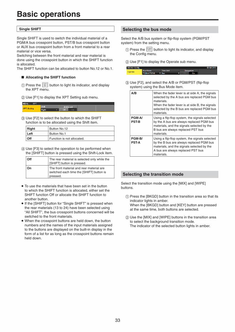
33
Basic operations
Single SHIFT
Single SHIFT is used to switch the individual material of a PGM/A bus crosspoint button, PST/B bus crosspoint button or AUX bus crosspoint button from a front material to a rear material or vice versa.Switching between the front material and rear material is done using the crosspoint button in which the SHIFT function is allocated.The SHIFT function can be allocated to button No.12 or No.1.
w Allocating the SHIFT function
1Press the XPTMV button to light its indicator, and display
the XPT menu.
2Use [F1] to display the XPT Setting sub menu.
3Use [F2] to select the button to which the SHIFT function is to be allocated using the Shift item.
Right Button No.12
Left Button No.1
Off Function is not allocated.
4Use [F3] to select the operation to be performed when the [SHIFT] button is pressed using the Shift-Lock item.
Off The rear material is selected only while the [SHIFT] button is pressed.
On The front material and rear material are switched each time the [SHIFT] button is pressed.
p To use the materials that have been set in the button to which the SHIFT function is allocated, either set the SHIFT function Off or allocate the SHIFT function to another button. p If the [SHIFT] button for “Single SHIFT” is pressed when the rear materials (13 to 24) have been selected using “All SHIFT”, the bus crosspoint buttons concerned will be switched to the front materials.
pWhen the crosspoint buttons are held down, the button numbers and the names of the input materials assigned to the buttons are displayed on the built-in display in the form of a list for as long as the crosspoint buttons remain held down.
Selecting the bus mode
Select the A/B bus system or flip-flop system (PGM/PST system) from the setting menu.
1Press the CONFSYS button to light its indicator, and display
the Config menu.
2Use [F1] to display the Operate sub menu.
3Use [F2], and select the A/B or PGM/PST (flip-flop system) using the Bus Mode item.
A/B When the fader lever is at side A, the signals selected by the A bus are replaced PGM bus materials.When the fader lever is at side B, the signals selected by the B bus are replaced PGM bus materials.
PGM-A/PST-B
Using a flip-flop system, the signals selected by the A bus are always replaced PGM bus materials, and the signals selected by the B bus are always replaced PST bus materials.
PGM-B/PST-A
Using a flip-flop system, the signals selected by the B bus are always replaced PGM bus materials, and the signals selected by the A bus are always replaced PST bus materials.
Selecting the transition mode
Select the transition mode using the [MIX] and [WIPE] buttons.
1Press the [BKGD] button in the transition area so that its indicator lights in amber. When the [BKGD] button and [KEY] button are pressed at the same time, both buttons are selected.
2Use the [MIX] and [WIPE] buttons in the transition area to select the background transition mode. The indicator of the selected button lights in amber.

34
Basic operations
Manual transition
Operate the fader lever to execute transitions manually.If the fader lever has been operated during auto transition, auto transition will be switched to manual operation as soon as the fader position overtakes the amount of the transition being executed.The bus tally LEDs on the left of the fader lever indicate the program bus output status.
Top LED only lights PGM/A bus output
Top and bottom LEDs light
During the transition
Bottom LED only lights
PST/B bus output
Auto transition
pp When the [AUTO] button is pressed, the transition is executed automatically using the transition time which has been set.pp The transition is executed in the remaining time when the
[AUTO] button is pressed while the fader lever is being operated.pp The auto transition time is set using the Time menu.
1Press the TIMECAM button to light its indicator, and display
the Time menu.
2Use [F1] to display the BKGD sub menu.
3Use [F2] to set the transition time in frames.
The display unit is set by selecting Config menu Operate sub menu Time Unit item.
Sec The time is displayed as a number of seconds.
Frame The time is displayed as a number of frames.
Any time from 0 to 999f can be set. The time which can be set when seconds are used as the display unit differs depending on the system format.
59.94i: max. 33s09f 59.94p: max. 16s39f
50i: max. 39s24f 50p: max. 19s49f
29.97PsF: max. 33s09f 29.97p: max. 33s09f
25PsF: max. 39s24f 25p: max. 39s24f
24PsF: max. 41s15f 24p: max. 41s15f
23.98PsF: max. 41s15f 23.98p: max. 41s15f
Cut transition
When the [CUT] button is pressed, the transition is executed instantly.

35
Basic operations
Wipe
Selecting the wipe pattern
The wipe patterns are selected using the number keys.
1Press the [BKGD PATT] button (or [KEY PATT] button). The [BKGD PATT] button (or [KEY PATT] button) indicator lights in amber, and the pattern table screen appears on the built-in display.
2Use [F1] to select the page.
3Use one of the number keys to select the pattern.
4Use [F5] to close the table screen.
p The table screen can also be closed by pressing the [BKGD PATT] button or [KEY PATT] button and turning off the button’s indicator.
pw Table of wipe patterns
pp The “SQ2: 8” pattern takes effect when the [KEY PATT] button has been pressed.pp When in 4K mode, only WIPE 1 and WIPE 2 are available. The other patterns are available with the optional 4K DVE unit
(AV-UHS5M5).
VMEM
BKGDPATT
XPTDSBL
TAKEENTER
7NEW
8COPY
9PASTE
4INS
5DEL
6MOD
1<
2>
3REV
0/10<<
.>>
CUNDO
CAMCONT
KEYPATT
-/+PAGE
MEMORY / WIPE PATTERN / 10 KEY
STILL 1 STILL 2 TRIM IN REC
CLIP 1 CLIP 2 TRIM OUT
< > REV
<< >> TRIM OFF PLAY
STOP
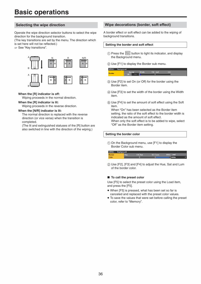
36
Basic operations
Selecting the wipe direction
Operate the wipe direction selector buttons to select the wipe direction for the background transition. (The key transitions are set by the menu. The direction which is set here will not be reflected.) See “Key transitions”.
A
N
B
B
A
B
A
B
A
B
R
A
A B
A
N/R
B
A B
When the [R] indicator is off: Wiping proceeds in the normal direction.
When the [R] indicator is lit: Wiping proceeds in the reverse direction.
When the [N/R] indicator is lit: The normal direction is replaced with the reverse
direction (or vice versa) when the transition is completed. (The lit and extinguished statuses of the [R] button are also switched in line with the direction of the wiping.)
Wipe decorations (border, soft effect)
A border effect or soft effect can be added to the wiping of background transitions.
Setting the border and soft effect
1Press the BKGDCBGD button to light its indicator, and display
the Background menu.
2Use [F1] to display the Border sub menu.
3Use [F2] to set On (or Off) for the border using the Border item.
4Use [F3] to set the width of the border using the Width item.
5Use [F4] to set the amount of soft effect using the Soft item. When “On” has been selected as the Border item setting, the ratio of the soft effect to the border width is indicated as the amount of soft effect. When only the soft effect is to be added to wipe, select “Off” as the Border item setting.
Setting the border color
1On the Background menu, use [F1] to display the Border Color sub menu.
2Use [F2], [F3] and [F4] to adjust the Hue, Sat and Lum of the border color.
w To call the preset color
Use [F5] to select the preset color using the Load item, and press the [F5].
pWhen [F5] is pressed, what has been set so far is canceled and replaced with the preset color values. p To save the values that were set before calling the preset color, refer to “Memory”.

37
Basic operations
Setting the wipe start position
Wipe start can be set at any desired position.
Target patterns:WIPE1: 5WIPE2: 4, 5, 6, 7SQ1: 5SQ2: 4, 5, 6, 7
The WIPE pattern is set using the Position sub menu of the Background menu (or Key menu).
1Press the BKGDCBGD button (or KEY1
CKEY button) to light its indicator, and display the Background menu (or Key menu).
2Use [F1] to display the Position sub menu.
3Either operate the positioners or use [F2] and [F3] to set the wipe start position using the X-Pos item and Y-Pos item. This setting is possible only if the target pattern has been selected for the background or key pattern.
4Either operate the fader lever or press the [AUTO] button to check the wipe operation. (When, for instance, –50 has been set for X-Pos and –50 for Y-Pos, the following screen (or key) appears from the bottom left and wipe is performed while the screen (or key) moves to the screen center.)
<X-Pos, Y-Pos setting range>
Inside screen area Outside screen area
5To copy the start position setting, press [F5] (Copy To Key1 or Copy To BKGD). The background setting is copied to the key setting while the key setting is copied to the background setting.
Modifying wipe
Setting the 3D (page turning) effect
A lighting effect can be added to a wipe pattern.Alternatively, the page turning effect parameter can be set.These effects can be set for background transitions and key transitions.
Target patterns:3D1: 1, 3, 7, 9
1Press the BKGDCBGD button (or KEY1
CKEY button) to light its indicator, and display the Background menu (or Key menu).
2Use [F1] to display the 3D Modify sub menu.
3Use [F2] to select whether the lighting effect is to be added using the Light item.
On The lighting effect is added.
Off The lighting effect is not added.
4Use [F3] to set the size when images have been reduced using the Size item.
5Use [F4] to set the radius of the page turning effect using the Radius item.
6Use [F5] to set the direction of the page turning effect using the Angle item.
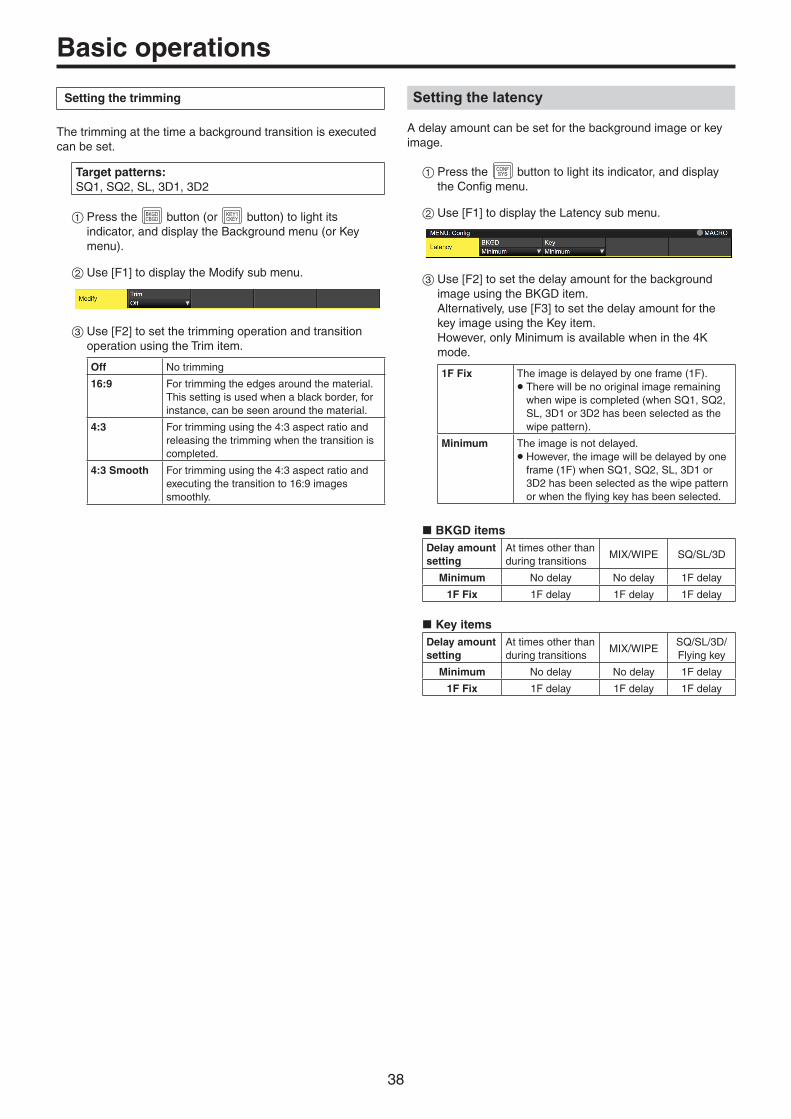
38
Basic operations
Setting the trimming
The trimming at the time a background transition is executed can be set.
Target patterns:SQ1, SQ2, SL, 3D1, 3D2
1Press the BKGDCBGD button (or KEY1
CKEY button) to light its indicator, and display the Background menu (or Key menu).
2Use [F1] to display the Modify sub menu.
3Use [F2] to set the trimming operation and transition operation using the Trim item.
Off No trimming
16:9 For trimming the edges around the material.This setting is used when a black border, for instance, can be seen around the material.
4:3 For trimming using the 4:3 aspect ratio and releasing the trimming when the transition is completed.
4:3 Smooth For trimming using the 4:3 aspect ratio and executing the transition to 16:9 images smoothly.
Setting the latency
A delay amount can be set for the background image or key image.
1Press the CONFSYS button to light its indicator, and display
the Config menu.
2Use [F1] to display the Latency sub menu.
3Use [F2] to set the delay amount for the background image using the BKGD item. Alternatively, use [F3] to set the delay amount for the key image using the Key item. However, only Minimum is available when in the 4K mode.
1F Fix The image is delayed by one frame (1F).p There will be no original image remaining
when wipe is completed (when SQ1, SQ2, SL, 3D1 or 3D2 has been selected as the wipe pattern).
Minimum The image is not delayed.p However, the image will be delayed by one
frame (1F) when SQ1, SQ2, SL, 3D1 or 3D2 has been selected as the wipe pattern or when the flying key has been selected.
w BKGD itemsDelay amount setting
At times other than during transitions
MIX/WIPE SQ/SL/3D
Minimum No delay No delay 1F delay
1F Fix 1F delay 1F delay 1F delay
w Key itemsDelay amount setting
At times other than during transitions
MIX/WIPESQ/SL/3D/Flying key
Minimum No delay No delay 1F delay
1F Fix 1F delay 1F delay 1F delay

39
Basic operations
Creating an animated wipe
You can create an animated wipe by linking a video (CLIP) registered in the video memory and an ME transition.
1Press the BKGDCBGD button to light its indicator, and display
the Background menu.
2Use [F1] to display the Transition Time sub menu.
3Use [F2] to set the BKGD transition time in the Trans Time item.
4Use [F3] to set the time to wait before starting the BKGD transition time in the WaitTime item. Press [F4] to enable/disable the WaitTime. The WaitTime is disabled if the settings is Off, irrespective of the WaitTime setting.
5Use [F1] to display the Transition Margin sub menu.
6Press [F2] to enable/disable the function for adjusting BKGD AUTO transition start/end margin in the Margin item.
7Use [F3] to adjust the BKGD AUTO transition start margin in the Start item. The End setting is automatically adjusted if the total when added with the End setting exceeds 10.0.
8Use [F4] to adjust the BKGD AUTO transition end point margin in the End item. The Start setting is automatically adjusted if the total when added with the Start setting exceeds 10.0.
9Use [F1] to display the Clip Trans Sync sub menu.
Use [F2] to set the Clip1 trigger in the Clip1 item.
Triggers can be assigned to the following buttons:AUTO, KEY1 ON, KEY2 ON, KEY3 ON, DSK1 ON, DSK2 ON, FTB ON, FaderAlso use [F3] to set the Clip2 trigger in the Clip2 item.However, only Clip1 is displayed when in the 4K mode.
Key
This operation combines the background image with another image. The key definition can be adjusted, and an edge can be added to the combined image.
Key1, Key2, Key3, DSK1 (downstream key), and DSK2 are available as materials to compose the background images.The default settings for priority (image positioning) are as shown in the figure below.
<Priority default settings>
Key1
Key2
Key3
DSK1
DSK2
Background image
You can change the prioritization for Key1, Key2, and Key3, and the prioritization for DSK1 and DSK2. Refer to “Setting the priority”.
How key combinations work is shown in the figure below.
<How key composition works>
UHS500
UHS500
Background
Key source
Key fill
Output image Invert

40
Basic operations
Selecting the key type
1Press the KEY1CKEY button to light its indicator, and display
the Key menu.
2Use [F1] to display the Key sub menu.
3Use [F2] to select the Type item.
Lum (luminance key/self key)
This is for creating the key signals from the luminance component or luminance and chroma component of the key fill signal.
Linear (linear key/ EXT key)
This is for creating the key signals from the luminance component of the key source signal. It is used when the key source signal and key fill signal are different.
Chroma (chroma key/ self key)
This is for creating the key signals using a specific hue of the key fill signal as the reference.
Full (full key/self key)
This is for creating the key signals using the images on the full screen as the key source signals.PinP combinations are possible in conjunction with the flying key. See “Flying key”.
Since the luminance and chroma keys are operated as self keys, the key fill signals are used as the key source signals. For the full key, the images on the full screen are used as the key source signals. When the luminance key, chroma key or full key has been selected as the key type, the key signals will remain unchanged even when the key source signals are switched.
When using the linear key, use material with a black background and white characters or shape to be combined by the key as the key source signal. Material which is not black and white may not be combined clearly.Material with a white background and black characters, etc. can be reversed using the key invert function for use.
4When the luminance key has been selected, the chroma component can be included in the generation of the key signals in view of the self key application. (This does not apply to the linear key.) Use [F3], and select the setting using the Lum Key item.
Chroma On In addition to the luminance component, the chroma component is also taken into account in the generation of the key signals.This is the setting for using a color with a low luminance component for the key signals (such as when defining blue characters).
Chroma Off The key signals are generated from only the luminance component.
5Use [F4] to select the fill type using the Fill item.
Bus The bus signal is used for the key fill signal.
Matte The internal fill matte is used for the key fill signal.

41
Basic operations
Selecting the key material
Selecting the key fill and key source signals
Press the [KEY] button in the AUX bus selection area, and switch the selection of the key fill signal (indicator lights in amber) and key source signal (indicator lights in green).
<Selecting the key fill signal>With the indicator of the [KEY] button lit in amber, press one of the AUX bus crosspoint buttons 1 to 12 to select the key fill signal.The indicator of the selected AUX bus crosspoint button lights in amber. (It will light in red if the selected signal is being output from the PGM connector.)
KEY1F/S
KEY2F/S
KEY3F/S
DSK1F/S
DSK2F/S
MV1MV2
PGMPVW
DISPCAM
AUX BUS DELEGATION AUX /DISP SOURCEAMBER : FILL / GREEN : SOURCE
AUX1
AUX
AUX2 AUX3 AUX4
SHIFT
Lighting in amber
<Selecting the key source signal>With the indicator of the [KEY] button lit in green, press one of the AUX bus crosspoint buttons 1 to 12 to select the key source signal.The indicator of the selected AUX bus crosspoint button lights in green. (It will light in red if the selected signal is being output from the PGM connector.)Since the luminance and chroma keys are operated as self keys, the key fill signals are used as the key source signals. When the luminance key or chroma key has been selected as the key type, the key signals will remain unchanged even when the key source signals are switched.
KEY1F/S
KEY2F/S
KEY3F/S
DSK1F/S
DSK2F/S
MV1MV2
PGMPVW
DISPCAM
AUX BUS DELEGATION AUX /DISP SOURCEAMBER : FILL / GREEN : SOURCE
AUX1
AUX
AUX2 AUX3 AUX4
SHIFT
Lighting in green
Linking the key fill signal and key source signal selection
1Press the KEY button to be used to display the menu.(KEY1/KEY2/KEY3)
2Use [F1] to display the Key Signal Coupling sub menu and set Independent.
3Press the CONFSYS button to light its indicator, and display
the Config menu.
4Use [F1] to display the Key Signal Coupling1 sub menu and set Fill/Source.
5Use [F1] to display the Key Signal Coupling2 to 8 sub menu.
p If Key Signal Coupling1 is Fill to Source, select what to use as the Source for the Fill. p Alternatively, if it is Source to Fill, select what to use as the Fill for the selected Source.
<Independent>When the [KEY] button lights in amber, the key fill signal can be selected, and when it lights in green, the key source signal can be selected.Independent
ON If Fill to Source, you can independently set a Source that is linked to Fill and separate from other KEYs.If Source to Fill, you can independently set a Fill that is linked to Source and separate from other KEYs.
OFF Settings accord with Key Signal Coupling2 to 8.

42
Basic operations
<Fill To Source>When the key fill signal is selected, the key source signal also switches automatically.Initially, the key source signal and the key fill signal will be the same signal.For example, when “SDI1” is selected for the key fill signal, the key source signal also becomes “SDI1”.After that, when the [KEY] button is pressed and lights in green, “SDI2” is selected for the key source signal. At this time, combination data indicating that the key fill signal is “SDI1” and the key source signal is “SDI2” is recorded on the unit.After the key fill signal and key source signal have been switched to other signals to perform another operation, if the key fill signal is then selected and set to “SDI1”, the saved combination data causes the key source signal to automatically switch to “SDI2”.If the key source signal is changed while the key fill signal is set to “SDI1”, the combination data is updated to reflect the change, and is recorded on the unit.
<Source To Fill>When the key source signal is selected, the key fill signal switches automatically.(The [KEY] button first lights amber.)
The initial values for the key source signal and the key fill signal are the same.
Setting the fill matte color
1Press the KEY1CKEY button to light its indicator, and display
the Key menu.
2Use [F1] to display the Fill Matte sub menu.
3Use [F2], [F3] and [F4] to adjust the Hue, Sat and Lum of the fill matte.
w To call the preset color
Use [F5] to select the preset color using the Load item, and press the [F5].
pWhen [F5] is pressed, what has been set so far is canceled and replaced with the preset color values. p To save the values that were set before calling the preset color, refer to “Memory”.
Key transitions
1Select the transition mode. Press the [KEY] button in the transition area to light its indicator. To execute a background transition and key transition at the same time, press the [BKGD] button and [KEY] button together to turn on both indicators.
FTBON
KEY1ON
KEY2ON
KEY3ON
DSK1ON
DSK2ON
MEMORY / WIPE PATTERN / 10 KEY
WIPE DIRECTION
MACRO N/R
BKGD KEY
MIX
CUT AUTO
MIX MIX
WIPE
WIPE WIPE
R
2Select the transition type. Use the [MIX] button or [WIPE] button in the transition area to select the key transition mode. The selected button lights in amber, and the MIX or WIPE status indicator LED depending on the selected mode lights. If WIPE has been selected, press the [KEY PATT] button in the memory/wipe pattern/number key area to light its indicator, and select the wipe pattern.
VMEM
BKGDPATT
XPTDSBL
TAKEENTER
7NEW
8COPY
9PASTE
4INS
5DEL
6MOD
1<
2>
3REV
0/10<<
.>>
CUNDO
CAMCONT
KEYPATT
-/+PAGE
MEMORY / WIPE PATTERN / 10 KEY
STILL 1 STILL 2 TRIM IN REC
CLIP 1 CLIP 2 TRIM OUT
< > REV
<< >> TRIM OFF PLAY
STOP
3Set the time of the transition. On the Time menu, use [F1] to display the Key sub menu. As with a background transition, set the transition time.

43
Basic operations
4Set the wipe direction. On the Key menu, use [F1] to display the Transition sub menu. Use [F1] to set “Normal” or “Reverse” using the Keyout Pattern item.
Normal The key out pattern moves in the same direction as the key in pattern.
Reverse The key out pattern moves in the opposite direction from the key in pattern.
<Pattern examples>
Pattern example 1 Pattern example 2Pattern example 3p WIPE1: 5p WIPE2: 1 to 7
Pattern example 4p SQ1: 5p SQ2: 1, 2, 4 to 7p 3D1: 5p 3D2: 1 to 3
Key in SQSQ
Key out (Normal)
SQSQ
Key out (Reverse)
SQSQ
: This indicates the areas where keys are combined.
p The operations for pattern example 3 are performed for the “WIPE1: 5” and “WIPE2: 1 to 7” patterns. p The operations for pattern example 4 are performed for the “SQ1: 5”, “SQ2: 1, 2, 4 to 7”, “3D1: 5” and “3D2: 1 to 3” patterns. The same operations are performed for normal and reverse.
5Execute the transition. Press the [AUTO] button in the transition area to automatically execute the transition at the transition time that has been set. Alternatively, execute the transition manually by operating the fader lever.
Key auto transition
When the [KEY ON] button in the transition area is pressed, the transition is automatically executed at the transition time that has been set.During key in, the indicator of the [KEY ON] button blinks in red, and it lights in red when the transition is completed.If the [KEY ON] button is pressed with the picture completely keyed in, the Key image transition (key out) is executed.During key out, the indicator of the [KEY ON] button lights in red, and it goes off when the transition is completed. If the [KEY ON] button is pressed during the transition, the transition direction is reversed.

44
Basic operationsKey preview
Key preview images can be output to the preview output, and the keys can be adjusted and checked.
1From the Key menus and the DSK menus, use [F1] to display the Key1/Key2/Key3/DSK1/DSK2 menus.
Key1 menu
Key2/Key3/DSK1/DSK2 menu
Linking of Menus
The PVW settings of Key2, Key3, DSK1, and DSK2 are linked as shown below.Key1, which can be set so that it can be operated with AUTO, CUT, and fader when the panel KEY button is ON, can be operated independently because it is different from the other Keys and DSKs.
PVW Key1 Key2 Key3 DSK1 DSK2
Key1On ––– ––– ––– –––
Off ––– ––– ––– –––
Key2On ––– Off Off Off
Off ––– ––– ––– –––
Key3On ––– Off Off Off
Off ––– ––– ––– –––
DSK1On ––– Off Off Off
Off ––– ––– ––– –––
DSK2On ––– Off Off Off
Off ––– ––– ––– –––
Off: Setting is changed to forced Off.
---: No change
PVW images:When PVW is OFF:
The PGM status is displayed in the PVW.This is not reflected in the transition status, however.
When PVW is ON:When PVW is set to “On”, the PGM images are displayed after the PVW.You can set PVW to “On” for only one of Key2, Key3, DSK1, or DSK2.Key1 is independent, so a maximum of 2 Keyers can be put on the PVW.
When PVW is Auto:PVW can be set to “Auto” only for Key1.When you press a KEY button in the transition area, the following two statuses are switched:
· When the KEY button is lit, the operation is with PVW “On”.
· When the KEY button is off, the operation is with PVW “Off”.
Background of the PVW:The BKGD image for PVW is modified by the PVW setting and the setting status of the BKGD and KEY buttons in the transition area.Basically there will be PGM images when either Key PVW or DSK PVW is “On”.However, these will become PST when both the BKGD and KEY buttons in the transition area are “On”.
When a user button to which the On/Off settings have been allocated is pressed, the setting is switched alternately between On (button indicator lights) and Off (button indicator extinguished), and the “Auto” setting is not selected.(The relevant user button items are KEY1_PVW/KEY2_PVW/KEY3_PVW/DSK1_PVW/DSK2_PVW.)
Menu User button When the user button is pressed
On Lights Off: Extinguished
Off Extinguished On: Lights
Auto Extinguished On: Lights
When “Auto” is selected using a menu operation, the user button indicator is turned off (extinguished).

45
Basic operations
Adjusting the luminance key and linear key
These steps are taken to adjust the luminance key and linear key definition.
1Press the KEY1CKEY button to light its indicator, and display
the Key menu.
2Use [F1] to display the Adjust sub menu.
3Use [F2], [F3] and [F4] to adjust the key definition.
4Use [F5] to set key invert. When “On” is selected, the key signals to be generated internally are inverted.
Operation/Parameter
Description of setting Setting range
F2/Clip
Reference level for generating key signals
0.0 to 108.0
F3/Gain
Key amplitude 0.0 to 200.0
F4/Density
Key density 0.0 to 100.0
F5/Invert
Key signal inversion On, Off
Adjusting the chroma key
Sampling is executed for the selected key materials to adjust those aspects of the key that are to be compensated.
Step 1
w To execute the sampling automatically
1Press the KEY1CKEY button to light its indicator, and display
the Chroma Key menu.
2Use [F1] to display the Auto Compute sub menu.
3Press [F2] to execute the sampling automatically. To undo what has been sampled, press [F5].
w To execute the sampling manually
1Press the KEY1CKEY button to light its indicator, and display
the Chroma Key menu.
2Use [F1] to display the Sample sub menu.
3Use [F2] to select “Composite” (composite image that combines the background image and key) using the View item.
4Use [F3] to select “Select BG” using the Mode item.
Select BG A color for the background of the foreground image is specified.Normally, either a blue or green background is specified.
5Use the positioner to move the position of the sample marker. To change the size of the sample marker, turn the rotary encoder [Z].
6If the sample area that has been set is acceptable, press the rotary encoder [Z]. The area that has been set is now sampled.
7To return to the pre-sampling status after sampling has been executed, press [F5].

46
Basic operations
Step 2
The objective of this step is to remove the noise in the background image.The noise is removed by carrying out this step several times.
1On the Chroma Key menu, use [F1] to display the Sample sub menu.
2Use [F2] to select “Matte” (Matte image) using the View item.
3Use [F3] to select “Clean BG” using the Mode item.
Clean BG The noise in the background image is removed.
4Using the positioner, move the position of the sample marker to the position of the noise (white dots) in the background image. To change the size of the sample marker, turn the rotary encoder [Z].
5If the sample area that has been set is acceptable, press the rotary encoder [Z]. The noise in the area that has been set is now removed.
6To return to the pre-sampling status after sampling has been executed, press [F5].
After the noise is removed
Before the noise is removed
Step 3
The objective of this step is to remove the noise in the foreground image.The noise is removed by carrying out this step several times.
1Use [F2] to select “Matte” (Matte image) using the View item.
2Use [F3] to select “Clean FG” using the Mode item.
Clean FG The noise in the foreground image is removed.
3Using the positioner, move the position of the sample marker to the position of the noise (black dots) in the foreground image. To change the size of the sample marker, turn the rotary encoder [Z].
4If the sample area that has been set is acceptable, press the rotary encoder [Z]. The noise in the area that has been set is now removed.
5To return to the pre-sampling status after sampling has been executed, press [F5].
After the noise is removed
Before the noise is removed
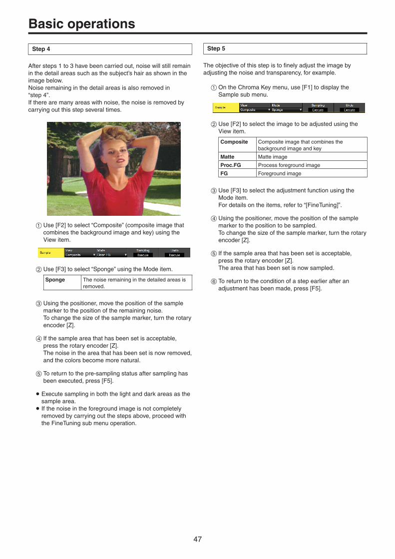
47
Basic operations
Step 4
After steps 1 to 3 have been carried out, noise will still remain in the detail areas such as the subject’s hair as shown in the image below.Noise remaining in the detail areas is also removed in “step 4”.If there are many areas with noise, the noise is removed by carrying out this step several times.
1Use [F2] to select “Composite” (composite image that combines the background image and key) using the View item.
2Use [F3] to select “Sponge” using the Mode item.
Sponge The noise remaining in the detailed areas is removed.
3Using the positioner, move the position of the sample marker to the position of the remaining noise. To change the size of the sample marker, turn the rotary encoder [Z].
4If the sample area that has been set is acceptable, press the rotary encoder [Z]. The noise in the area that has been set is now removed, and the colors become more natural.
5To return to the pre-sampling status after sampling has been executed, press [F5].
p Execute sampling in both the light and dark areas as the sample area. p If the noise in the foreground image is not completely removed by carrying out the steps above, proceed with the FineTuning sub menu operation.
Step 5
The objective of this step is to finely adjust the image by adjusting the noise and transparency, for example.
1On the Chroma Key menu, use [F1] to display the Sample sub menu.
2Use [F2] to select the image to be adjusted using the View item.
Composite Composite image that combines the background image and key
Matte Matte image
Proc.FG Process foreground image
FG Foreground image
3Use [F3] to select the adjustment function using the Mode item. For details on the items, refer to “[FineTuning]”.
4Using the positioner, move the position of the sample marker to the position to be sampled. To change the size of the sample marker, turn the rotary encoder [Z].
5If the sample area that has been set is acceptable, press the rotary encoder [Z]. The area that has been set is now sampled.
6To return to the condition of a step earlier after an adjustment has been made, press [F5].
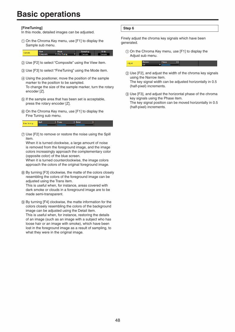
48
Basic operations
[FineTuning]In this mode, detailed images can be adjusted.
1On the Chroma Key menu, use [F1] to display the Sample sub menu.
2Use [F2] to select “Composite” using the View item.
3Use [F3] to select “FineTuning” using the Mode item.
4Using the positioner, move the position of the sample marker to the position to be sampled. To change the size of the sample marker, turn the rotary encoder [Z].
5If the sample area that has been set is acceptable, press the rotary encoder [Z].
6On the Chroma Key menu, use [F1] to display the Fine Tuning sub menu.
7Use [F2] to remove or restore the noise using the Spill item. When it is turned clockwise, a large amount of noise is removed from the foreground image, and the image colors increasingly approach the complementary color (opposite color) of the blue screen. When it is turned counterclockwise, the image colors approach the colors of the original foreground image.
8By turning [F3] clockwise, the matte of the colors closely resembling the colors of the foreground image can be adjusted using the Trans item. This is useful when, for instance, areas covered with dark smoke or clouds in a foreground image are to be made semi-transparent.
9By turning [F4] clockwise, the matte information for the colors closely resembling the colors of the background image can be adjusted using the Detail item. This is useful when, for instance, restoring the details of an image (such as an image with a subject who has loose hair or an image with smoke), which have been lost in the foreground image as a result of sampling, to what they were in the original image.
Step 6
Finely adjust the chroma key signals which have been generated.
1On the Chroma Key menu, use [F1] to display the Adjust sub menu.
2Use [F2], and adjust the width of the chroma key signals using the Narrow item. The key signal width can be adjusted horizontally in 0.5 (half-pixel) increments.
3Use [F3], and adjust the horizontal phase of the chroma key signals using the Phase item. The key signal position can be moved horizontally in 0.5 (half-pixel) increments.

49
Basic operations
Key decorations
A border, shadow or other edge can be added to the key.
Setting the key edge
1Press the KEY1CKEY button to light its indicator, and display
the Key menu.
2Use [F1] to display the Edge1 sub menu.
3Use [F2] to select the edge type.
Off An edge is not added.
Border A border is added around the entire edge.
Drop A diagonal border is added.
Shadow A shadow is added.
Outline An outline (only a border with no fill) is added.
Border Drop
OutlineShadow
4Use [F3] to set the edge width.
5Use [F4] to set the direction (in 45-degree increments) in which “Drop” and “Shadow” will be added.
(Top)
(Bottom)
(Right)(Left)
225180 270
135 315
4590 0
6Use [F5] to set the darkness (Density) of the edges.
Selecting the Edge Fill settings
Materials to be inserted as edges can be set.
1On the Key menu, use [F1] to display the Edge2 sub menu.
2Use [F2] to select the edge material using the Edge Fill items.
Color The color set using Edge Color is used.
CBGD1The color background is used.
CBGD2
Still1 The still image video memory (Still1) is used.
Still2 The still image video memory (Still2) is used.
Clip1 The moving image video memory (Clip1) is used.
Clip2 The moving image video memory (Clip2) is used.
p Still2 and Clip2 cannot be selected in 4K mode.
Setting the edge color
1On the Key menu, use [F1] to display the Edge Color sub menu.
2Use [F2], [F3] and [F4] to adjust the Hue, Sat and Lum of the edge color.
w To call the preset color
Use [F5] to select the preset color using the Load item, and press the [F5].
pWhen [F5] is pressed, what has been set so far is canceled and replaced with the preset color values. p To save the values that were set before calling the preset color, refer to “Memory”.

50
Basic operations
Masking the key signals
These steps are taken to mask the key signals using the mask signal of the box pattern.
1Press the KEY1CKEY button to light its indicator, and display
the Key menu.
2Use [F1] to display the Mask sub menu.
3Use [F2], and select the masking method using the Mask item.
Off The key signals are not masked.
Manual The area that is set using the Mask Adjust sub menu is masked.
4:3 The signals are masked to the 4:3 aspect ratio.
4Use [F3] to set whether to invert the mask signal using the Invert item.
On The mask signal is inverted.
Off The mask signal is not inverted.
5Use [F1] to display the Mask Adjust sub menu.
6Use [F2] to [F5] to set the area to be masked.
Operation/Parameter
Description of setting
Setting range/Initial value
F2/Left
Key left position−50.00 to 50.00/−25.00
F3/Top
Key top position−50.00 to 50.00/
25.00
F4/Bottom
Key bottom position−50.00 to 50.00/−25.00
F5/Right
Key right position−50.00 to 50.00/
25.00
The Left setting cannot exceed the Right setting (and vice versa) and, similarly, the Top setting cannot exceed the Bottom setting (and vice versa).
<Key mask setting> (figure shows the default values)
0
50
-50 500-50
TOP (25)
BOTTOM (-25)
(25)RIGHT
(-25)LEFT
Area masked
Area where the key signal is effective
Video signal range
Flying key
Using DVE effects, this key enables the key signals that have been input to be moved, expanded or contracted. In order for the flying key to take effect, select “SQ2: 8” as the key transition. Refer to “Selecting the wipe pattern”.
When the key transition is executed, the keys are combined by the key signals set using the flying key menu. (The transition effect is fixed at MIX.)Since the flying key uses DVE effects, the image is delayed by one frame.
Key signal When combined using the flying key
ABC ABC
In order to add the edge of the key before the DVE effect, the thickness of the edge is also changed when the size is changed.
Adjusting position and size
1Press the KEY1CKEY button to light its indicator, and display
the Key menu.
2Use [F1] to display the Flying Key Position/Size sub menu.
3Use [F2] to set the X coordinate of the key signal using the X-Pos item.
4Use [F3] to set the Y coordinate of the key signal using the Y-Pos item.
5Use [F4] to set the key signal change size (max. 400: 400%) using the Size item.

51
Basic operations
Adjusting rotation
1Press the KEY1CKEY button to light its indicator, and display
the Key menu.
2Use [F1] to display the Flying Key Rotation sub menu.
3Use [F2] to set the X rotation of the key signal in the X item.
4Use [F3] to set the Y rotation of the key signal in the Y item.
5Use [F4] to set the Z rotation of the key signal in the Z item.
Adjusting aspect ratio
1Press the KEY1CKEY button to light its indicator, and display
the Key menu.
2Use [F1] to display the Flying Key Aspect sub menu.
3Use [F2] to set the horizontal ratio of the key signal in the X item.
4Use [F3] to set the vertical ratio of the key signal in the Y item.
PinP combinations using the flying key
When “Full” is selected using the Type item in “Selecting the key type”, PinP combinations can be performed using the flying key.(At this point in time, the Clip item and Gain item cannot be set on the Adjust sub menu.)
With the full key, the image on the full screen serves as the key source signal so an edge will not be added unless a further step is taken. To add an edge, mask the key signals so that the key source signals are made smaller than the entire screen. For details on masking, refer to “Masking the key signals”.
Setting the priority
The relative positions of the images when Key1, Key2 and Key3 images are to be superimposed onto one another can be set.
1Press the KEY1CKEY button (or KEY2
KEY3 button) to light its indicator, and display the Key menu.
2Use [F1] to display the Key Priority sub menu.
3Use [F2] to [F4] to set the relative positions using the 3rd item, 2nd item and 1st item.
1st This is used to set the image to be placed at the top.
2nd This is used to set the image to be placed in the middle.
3rd This is used to set the image to be placed at the bottom.
3rd: Key1
2nd: Key2
1st: Key3

52
Basic operations
PinP (picture in picture)
Another image can be combined with the background image.This unit supports PinP for 2 channels, DSK and Key.
Selecting the PinP channel and material
In 2K mode or HD mode:Press the [Key2] button among the AUX bus selector buttons.
In 4K mode or when there is no 4K DVE unit:Press the [Key1] button among the AUX bus selector buttons.
When the [Key2] button (or [Key1] button) is lit, the PinP menu is displayed on the built-in display.The state in which the PinP materials are selected is now established for the AUX bus crosspoint buttons.
The selected AUX bus crosspoint button lights in amber. (It will light in red if the selected signal is a PGM output signal.)
KEY1F/S
KEY2F/S
KEY3F/S
DSK1F/S
DSK2F/S
MV1MV2
PGMPVW
DISPCAM
AUX BUS DELEGATION AUX /DISP SOURCEAMBER : FILL / GREEN : SOURCE
AUX1
AUX
AUX2 AUX3 AUX4
SHIFT
Selecting Shape
Square, Circle, Heart, Flower or Star can be selected as the shape used for combining PinP images.
1Press the [Key2] button (2K/HD mode) or [Key1] button (in 4K mode or when there is no 4K DVE unit) to light the button and display the PinP menu.
2Use [F1] to display the PinP sub menu.
3Use [F4] and, using the Shape item, select the shape used for combining images.
4Use [F5] to adjust the transmissivity (darkness) applying when the images are combined using the Density item.
Full Key On/Off
1In the PinP sub menu, use [F3] to enable (On)/disable (Off) Full Key.
On Irrespective of the values set with the Key sub menu, PinP images are composed with Full Key.
Off PinP images are composed according to the values set with the Key sub menu.

53
Basic operations
PinP adjustments
Adjusting the PinP position and size
While the PinP menu is selected, adjust the X and Y coordinates using the positioner in the positioner area, and adjust the size using the rotary encoder [Z]. Alternatively, the settings can be performed on the menus.
1Press the [Key2] button (2K/HD mode) or [Key1] button (in 4K mode or when there is no 4K DVE unit) to light the button and display the PinP menu.
2Use [F1] to display the PinP Position sub menu.
3Either operate the positioner and the rotary encoder [Z] or use [F2], [F3] and [F4] to set the X and Y coordinates and the size using the X-Pos, Y-Pos and Size items.
Linking Key PinP and DSK PinP
The Key PinP and DSK PinP images perform a symmetrical operation for the axis whose coordinates and rotation angle have been set. The image serving as the reference is the PinP image of the menu being operated.
Linking Key PinP and DSK PinP
1Press the [Key2] button (2K/HD mode) or [Key1] button (in 4K mode or when there is no 4K DVE unit) to light the button and display the PinP menu.
2Use [F1] to display the PinP Sync sub menu.
3Use [F2] to select the position that will serve as the reference using the Sync item. The image serving as the reference is the PinP image of the menu being operated.
When “X” has been selected as the Symmetry setting
The coordinates and rotation angle are made symmetrical to the X axis.
When “Y” has been selected as the Symmetry setting
The coordinates and rotation angle are made symmetrical to the Y axis.
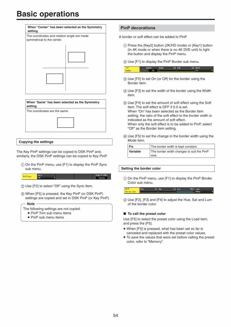
54
Basic operations
When “Center” has been selected as the Symmetry setting
The coordinates and rotation angle are made symmetrical to the center.
When “Same” has been selected as the Symmetry setting
The coordinates are the same.
Copying the settings
The Key PinP settings can be copied to DSK PinP and, similarly, the DSK PinP settings can be copied to Key PinP.
1On the PinP menu, use [F1] to display the PinP Sync sub menu.
2Use [F2] to select “Off” using the Sync item.
3When [F5] is pressed, the Key PinP (or DSK PinP) settings are copied and set in DSK PinP (or Key PinP).
The following settings are not copied. p PinP Trim sub menu items p PinP sub menu items
Note
PinP decorations
A border or soft effect can be added to PinP.
1Press the [Key2] button (2K/HD mode) or [Key1] button (in 4K mode or when there is no 4K DVE unit) to light the button and display the PinP menu.
2Use [F1] to display the PinP Border sub menu.
3Use [F2] to set On (or Off) for the border using the Border item.
4Use [F3] to set the width of the border using the Width item.
5Use [F4] to set the amount of soft effect using the Soft item. The soft effect is OFF if 0.0 is set. When “On” has been selected as the Border item setting, the ratio of the soft effect to the border width is indicated as the amount of soft effect. When only the soft effect is to be added to PinP, select “Off” as the Border item setting.
6Use [F5] to set the change in the border width using the Mode item.
Fix The border width is kept constant.
Variable The border width changes to suit the PinP size.
Setting the border color
1On the PinP menu, use [F1] to display the PinP Border Color sub menu.
2Use [F2], [F3] and [F4] to adjust the Hue, Sat and Lum of the border color.
w To call the preset color
Use [F5] to select the preset color using the Load item, and press the [F5].
pWhen [F5] is pressed, what has been set so far is canceled and replaced with the preset color values. p To save the values that were set before calling the preset color, refer to “Memory”.

55
Basic operations
Trimming settings
1Press the [Key2] button (2K/HD mode) or [Key1] button (in 4K mode or when there is no 4K DVE unit) to light the button and display the PinP menu.
2Use [F1] to display the Trim sub menu.
3Use [F2] to set the trimming On/Off in the Trim item.
On Trimming is performed.
Off No trimming
4Use [F3] to select the trimming type.
16:9 Automatic trimming so that the aspect ratio is 16:9.
12:9 Automatic trimming so that the aspect ratio is 12:9.
9:9 Automatic trimming so that the aspect ratio is 9:9.
7:9 Automatic trimming so that the aspect ratio is 7:9.
6:9 Automatic trimming so that the aspect ratio is 6:9.
Manual Trimming using the value set on the Trim sub menu.
5Use [F3] to set the Pair On/Off in the Pair item.
On The settings are changed in such a way that the Left and Right trimming amounts and the Top and Bottom trimming amounts are the same. (This makes for a top-bottom and left-right symmetry.)
Off Pair settings not made.
6Use [F1] to display the PinP Trim Adjust sub menu, and use [F2], [F3], [F4] and [F5] to set the trimming values.
Operation/Parameter
Description of setting
Setting range/Initial value
F2/Left
Trimming value at left
−50.00 to 50.00/−50.00
F3/Top
Trimming value at top
−50.00 to 50.00/50.00
F4/Bottom
Trimming value at bottom
−50.00 to 50.00/−50.00
F5/Right
Trimming value at right
−50.00 to 50.00/50.00
<Trimming settings> (figure shows the default values)
0
60
-60600-60
TOP (50)
BOTTOM (-50)
(-50)LEFT
(50)RIGHT
Area trimmed
Area where PinP is effective
Original size of PinP
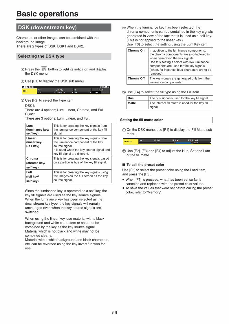
56
Basic operations
DSK (downstream key)
Characters or other images can be combined with the background image.There are 2 types of DSK; DSK1 and DSK2.
Selecting the DSK type
1Press the DSK1DSK2 button to light its indicator, and display
the DSK menu.
2Use [F1] to display the DSK sub menu.
3Use [F2] to select the Type item.
DSK1:There are 4 options; Lum, Linear, Chroma, and Full.DSK2:There are 3 options; Lum, Linear, and Full.
Lum (luminance key/ self key)
This is for creating the key signals from the luminance component of the key fill signal.
Linear (linear key/ EXT key)
This is for creating the key signals from the luminance component of the key source signal. It is used when the key source signal and key fill signal are different.
Chroma (chroma key/ self key)
This is for creating the key signals based on a particular hue of the key fill signal.
Full (full key/ self key)
This is for creating the key signals using the images on the full screen as the key source signal.
Since the luminance key is operated as a self key, the key fill signals are used as the key source signals. When the luminance key has been selected as the downstream key type, the key signals will remain unchanged even when the key source signals are switched.
When using the linear key, use material with a black background and white characters or shape to be combined by the key as the key source signal.Material which is not black and white may not be combined clearly.Material with a white background and black characters, etc. can be reversed using the key invert function for use.
4When the luminance key has been selected, the chroma components can be contained in the key signals generated in view of the fact that it is used as a self key. (This is not applied to the linear key.) Use [F3] to select the setting using the Lum Key item.
Chroma On In addition to the luminance components, the chroma components are also factored in when generating the key signals.Use this setting if colors with low luminance components are used for the key signals (when, for instance, blue characters are to be removed).
Chroma Off The key signals are generated only from the luminance components.
5Use [F4] to select the fill type using the Fill item.
Bus The bus signal is used for the key fill signal.
Matte The internal fill matte is used for the key fill signal.
Setting the fill matte color
1On the DSK menu, use [F1] to display the Fill Matte sub menu.
2Use [F2], [F3] and [F4] to adjust the Hue, Sat and Lum of the fill matte.
w To call the preset color
Use [F5] to select the preset color using the Load item, and press the [F5].
pWhen [F5] is pressed, what has been set so far is canceled and replaced with the preset color values. p To save the values that were set before calling the preset color, refer to “Memory”.

57
Basic operations
Selecting the DSK material
Selecting the DSK fill signal and DSK source signal
Press the [DSK] button in the AUX bus selection area to switch the selection of the DSK fill signal (indicator lights in amber) and DSK source signal (indicator lights in green).
<Selecting the DSK fill signal>
While the indicator of the [DSK] button is lit in amber, press one of the AUX bus crosspoint buttons 1 to 12 to select the DSK fill signal.The indicator of the selected AUX bus crosspoint button lights in amber. (It lights in red if the selected signal is being output from the PGM connector.)
KEY1F/S
KEY2F/S
KEY3F/S
DSK1F/S
DSK2F/S
MV1MV2
PGMPVW
DISPCAM
AUX BUS DELEGATION AUX /DISP SOURCEAMBER : FILL / GREEN : SOURCE
AUX1
AUX
AUX2 AUX3 AUX4
SHIFT
Lighting in amber
<Selecting the DSK source signal>
While the indicator of the [DSK] button is lit in green, press one of the AUX bus crosspoint buttons 1 to 12 to select the DSK source signal.The indicator of the selected AUX bus crosspoint button lights in green. (It lights in red if the selected signal is being output from the PGM connector.)Since the luminance key is operated as a self key, the key fill signals are used as the key source signals. When the luminance key has been selected as the downstream key type, the key signals will remain unchanged even when the key source signals are switched.
KEY1F/S
KEY2F/S
KEY3F/S
DSK1F/S
DSK2F/S
MV1MV2
PGMPVW
DISPCAM
AUX BUS DELEGATION AUX /DISP SOURCEAMBER : FILL / GREEN : SOURCE
AUX1
AUX
AUX2 AUX3 AUX4
SHIFT
Lighting in green
Linking the DSK fill signal and DSK source signal selection
1Press the CONFSYS button to light it, and display the Config
menu.
2Use [F1] to display the Key Signal Coupling1 sub menu.
3Use [F2] to select the linking method for the DSK fill signal and DSK source signal by using the Fill/Source item. Fill To Source When the DSK fill signal is selected, the DSK
source signal changes automatically.
Source To Fill When the DSK source signal is selected, the DSK fill signal changes automatically.
<Fill To Source>When the DSK fill signal is selected, the DSK source signal also switches automatically.Initially, the DSK source signal and the DSK fill signal will be the same signal.For example, when “SDI1” is selected for the DSK fill signal, the DSK source signal also becomes “SDI1”.After that, when the [DSK] button is pressed and lights in green, “SDI2” is selected for the DSK source signal. At this time, combination data indicating that the DSK fill signal is “SDI1” and the DSK source signal is “SDI2” is recorded on the unit.After the DSK fill signal and DSK source signal have been switched to other signals to perform another operation, if the DSK fill signal is then selected and set to “SDI1”, the saved combination data causes the DSK source signal to automatically switch to “SDI2”.If the DSK source signal is changed while the DSK fill signal is set to “SDI1”, the combination data is updated to reflect the change, and is recorded on the unit.
<Source To Fill>When the DSK source signal is selected, the DSK fill signal switches automatically.However, be aware that if the [DSK] button is pressed when it is not lit, the [DSK] button will first light green, and the mode will be that for selecting the DSK source signal.

58
Basic operations
The recorded combination information can be set from combinations of Coupling1 to 8 in the Key Signal Coupling sub menu.
The initial values for the DSK source signal and the DSK fill signal are the same.
Independently set the selection for the DSK fill signal and the DSK source signal
1From the DSK menu, use [F1] to display the DSK Signal Coupling sub menu.
2Use [F2] to set On/Off in the Independent item.
<Independent>When the [DSK] button lights in amber, the DSK fill signal can be selected, and when it lights in green, the DSK source signal can be selected.
DSK transitions
1Set the transition time. Press the TIME
CAM button to light its indicator, and display the Time menu.
2Use [F1] to display the DSK sub menu. As with background transitions, set the transition time. Refer to “Auto transition”.
3When the [DSK1 ON] or [DSK2 ON] button in the transition area is pressed, the DSK image is combined (fades in) for the length of the transition time that has been set.
During fade-in, the [DSK1 ON] or [DSK2 ON] button blinks in red, and when the transition (fades in) is completed, it lights in red. When the [DSK1 ON] or [DSK2 ON] button is pressed after fade-in is completed, the DSK image transitions (fades out). During fade-out, the [DSK1 ON] or [DSK2 ON] button lights in red, and when the transition (fades out) is completed, it goes off. If the [DSK1 ON] or [DSK2 ON] button is pressed at any point during a transition, the direction of the transition is reversed.

59
Basic operations
DSK preview
Select whether to output the DSK preview image to the preview output.
1Press the DSK1DSK2 button to light its indicator, and display
the DSK menu.
2Use [F1] to display the DSK sub menu.
3Use [F5] to set the PVW item.
On An image with the DSK effect added is output to the preview output.
Off An image without the DSK effect added is output to the preview output.
The PVW On and Off settings can be allocated to the user buttons. Refer to “Setting the user buttons”.
DSK adjustments
The DSK definition can be adjusted.
1Press the DSK1DSK2 button to light its indicator, and display
the DSK menu.
2Use [F1] to display the Adjust sub menu.
3Use [F2], [F3] and [F4] to adjust the DSK (downstream key) definition.
4Use [F5] to set key invert. If “On” is set, the key signals generated internally are inverted.
Operation/Parameter
Description of setting Setting range
F2/Clip
Reference level for generating key signals
0.0 to 108.0
F3/Gain
Key amplitude 0.0 to 200.0
F4/Density
Key density 0.0 to 100.0
F5/Invert
Key signal inversion On, Off
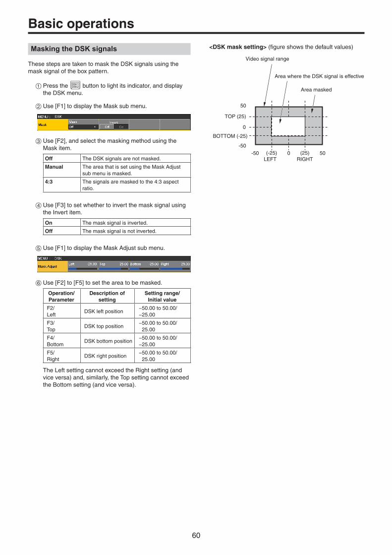
60
Basic operations
Masking the DSK signals
These steps are taken to mask the DSK signals using the mask signal of the box pattern.
1Press the DSK1DSK2 button to light its indicator, and display
the DSK menu.
2Use [F1] to display the Mask sub menu.
3Use [F2], and select the masking method using the Mask item.
Off The DSK signals are not masked.
Manual The area that is set using the Mask Adjust sub menu is masked.
4:3 The signals are masked to the 4:3 aspect ratio.
4Use [F3] to set whether to invert the mask signal using the Invert item.
On The mask signal is inverted.
Off The mask signal is not inverted.
5Use [F1] to display the Mask Adjust sub menu.
6Use [F2] to [F5] to set the area to be masked.
Operation/Parameter
Description of setting
Setting range/Initial value
F2/Left
DSK left position−50.00 to 50.00/−25.00
F3/Top
DSK top position−50.00 to 50.00/
25.00
F4/Bottom
DSK bottom position−50.00 to 50.00/−25.00
F5/Right
DSK right position−50.00 to 50.00/
25.00
The Left setting cannot exceed the Right setting (and vice versa) and, similarly, the Top setting cannot exceed the Bottom setting (and vice versa).
<DSK mask setting> (figure shows the default values)
0
50
-50 500-50
TOP (25)
BOTTOM (-25)
(25)RIGHT
(-25)LEFT
Area masked
Area where the DSK signal is effective
Video signal range

61
Basic operations
Key Link
Key1, Key2, and Key3 and DSK1 and DSK2 can be linked in Group1 to 4.
This function makes it possible to link the “On” or “Off” setting of the [DSK ON] button and [PinP] buttons ([PinP1 ON] and [PinP2 ON]) with the “On” or “Off” (button indicator lights or off) of the [KEY ON] button.
FTBON
KEY1ON
KEY2ON
KEY3ON
DSK1ON
DSK2ON
MEMORY / WIPE PATTERN / 10 KEY
WIPE DIRECTION
MACRO N/R
BKGD KEY
MIX
CUT AUTO
MIX MIX
WIPE
WIPE WIPE
R
1Press the Config button to be used to display the menu.
2Use [F1] to display the Key/DSK Link1 or 2 sub menu, then use Color Group1 to 8 to set the button color linked to each of the buttons.
p There is no linking if OFF is selected. p The button color for each of the buttons is set in the Color Group KEY ON and Color Group DSK/FTB ON sub menus.
Example:When KEY1 of Key/DSK Link1 is set to Color Group 1, then whichever of the KEY2 ON/KEY3 ON/DSK1 ON/DSK2 ON/FTB ON buttons is set to ON (illuminated), the KEY1 ON button will also be set to ON.
FTB (Fade to Black)
The user can fade out from a program image to the black screen/white screen/Still/Clip/color background screen or fade in to a program image from a black screen/white screen/Still/Clip/color background.
1Set the duration of the transition. Press the TIME
CAM button to light its indicator, and display the Time menu.
2Use [F1] to display the FTB sub menu. As with a background transition, set the transition time. Refer to “Auto transition”.
FTBON
KEY1ON
KEY2ON
KEY3ON
DSK1ON
DSK2ON
MEMORY / WIPE PATTERN / 10 KEY
WIPE DIRECTION
MACRO N/R
BKGD KEY
MIX
CUT AUTO
MIX MIX
WIPE
WIPE WIPE
R
3The screen fades out to the setting screen at the set transition time when you press the [FTB ON] button in the transition area.
During fade-out, the indicator of the [FTB ON] button blinks in red, and it lights in red when the transition (fade-out) is completed, and the black screen is displayed.* When the [FTB ON] button is pressed with the black screen displayed, fade-in to the program image is initiated. During fade-in, the indicator of the [FTB ON] button lights in red, and it goes off when the transition (fade-in) is completed. If the [FTB ON] button is pressed at any point during a transition, the direction of the transition is reversed.
*: In the FTB status, the crosspoint button which is normally lit in red lights in amber.

62
Basic operationsSelecting the image
The image to be used for fading out can be selected.
1Press the CONFSYS button to light its indicator, and display
the Config menu.
2Use [F1] to display the Assign sub menu.
3Use [F2] to select the image to appear when fading out using the FTB Source item.
Still1 The still image video memory (Still1) is used.
Still2 The still image video memory (Still2) is used.pp Selectable only in 2K mode.
Clip1 The moving image video memory (Clip1) is used.
Clip2 The moving image video memory (Clip2) is used.pp Selectable only in 2K mode.
CBGD1The color background is used.
CBGD2
White White background
Black Black background
Internal color signals
This unit supports two sets of internal color signals.
Setting the color background
The color background to be used by the bus can be set.Two methods are available: under one method the Hue (hue), Sat (color saturation) and Lum (luminance) are set, and under the other the 8 preset colors (white, yellow, cyan, green, magenta, red, blue and black) are called. The Hue, Sat and Lum of the called colors can also be adjusted.
Adjusting the colors
1Press the BKGDCBGD button to light its indicator, and display
the Color Background menu.
2Use [F1] to display the CBGD1 Main sub menu (or CBGD2 Main sub menu).
3Use [F2], [F3] and [F4] to perform the color adjustments (Hue, Sat and Lum).
w To call the preset color
Use [F5] to select the preset color using the Load item, and press the [F5].
pWhen [F5] is pressed, what has been set so far is canceled and replaced with the preset color values. p To save the values that were set before calling the preset color, refer to “Memory”.

63
Basic operations
Setting the Wash effect
The gradation effect for color backgrounds can be set.
Selecting the Wash effect and setting the colors
1Press the BKGDCBGD button to light its indicator, and display
the Color Background menu.
2Use [F1] to display the CBGD1 Wash sub menu (or CBGD2 Wash sub menu).
3Use [F2] to set the Wash (gradation) effect using the Wash item.
On The gradation effect is added.
Off The gradation effect is not added.
4Use [F3] to set the color of the Wash (gradation) effect using the Color item.
Dual A dual-color gradation effect is added. (This results in a gradation of two colors, namely, the CBGD1 Main color and the CBGD1 Sub color.)
Rainbow The rainbow color gradation effect is added.
5When “Dual” has been selected, use [F1] to display the CBGD1 Sub sub menu (or CBGD2 Sub sub menu), and set the sub color.
6Use [F2], [F3] and [F4] to adjust the colors (Hue, Sat and Lum).
Adjusting the Wash waveforms
1On the Color Background menu, use [F1] to display the CBGD1 Wave sub menu (or CBGD2 Wave sub menu).
2Use [F2] to select the gradation waveforms using the Pattern item.
Sine Sine waves are selected.
Saw Sawtooth waves are selected.
3Use [F3] to select the gradation cycle using the Cycle item.
4Use [F4] to select the gradation phase using the Phase item.
5Use [F5] to select the gradation angle using the Angle item.
Setting the Wash movements
1On the Color Background menu, use [F1] to display the CBGD1 Move sub menu (or CBGD2 Move sub menu).
2Use [F2] to set the gradation movement using the Move item.
Off No movement is set.
Roll The gradations are scrolled.
Rotation The gradations are rotated.
3Use [F3] to set the movement speed using the Speed item.
Internal color bar signal
The unit supports 1 internal color bar signal.
Test tone settings
The settings related to the test tone signals (1 kHz) output with color bar signals can be set.
1Press the CONFSYS button to light its indicator, and display
the System menu.
2Use [F1] to display the Test Tone sub menu.
3Use [F2] to set the test tone function in the Color Bar item.
Nomal Test tones are output at the normal volume (–12 dB).
Low Test tones are output at lower volume (–20 dB).
Off Test tones are not output.

64
Basic operations
Switching the AUX output
Selecting the AUX output materials
The output signals of the AUX buses (AUX1 to AUX4) can be selected.
1Press one of the [AUX1] to [AUX4] buttons among the AUX bus selector buttons. The selected button lights in amber.
2Press one of the AUX bus crosspoint buttons. The selected signal is output to the pressed [AUX1] to [AUX4] button.
KEY1F/S
PGMA
KEY2F/S
KEY3F/S
DSK1F/S
DSK2F/S
MV1MV2
PGMPVW
DISPCAM
AUX BUS DELEGATION AUX /DISP SOURCEAMBER : FILL / GREEN : SOURCE
AUX1
AUX
AUX2 AUX3 AUX4
SHIFT
The button with the signals selected by AUX1 lights in amber.
<Signals that can be selected by the AUX bus>
Name of signal Description of signal
IN1, IN2 SDI/HDMI input signal 1, 2
SDI IN3 to SDI IN8 SDI input signal 3 to 8
IN-A1 to 4, IN B1 to 4
Option slot input signal(SDI, HDMI)
PGM Program video signal
PVW Preview video signal
CLN Clean signal
MV1, MV2 Multi view display output signal 1, 2
KeyOut Key output signal
BLACK Black signal
CBGD1, CBGD2 Color background 1, 2
CBAR Color bar
Still1, Still2 Video memory (still image) 1, 2pp Still2 is selectable only in 2K mode.
Clip1, Clip2 Video memory (moving image) 1, 2pp Clip2 is selectable only in 2K mode.
pWhen the AUX bus for which “MV” has been selected is displayed on the sub screen of the multi view display, the images are looped as if two mirrors were facing each other.
AUX1/2 transitions
The MIX transition is executed when the output signal set for AUX1/2 is switched.
1Press the [AUX1] or [AUX2] button of the AUX bus selector buttons. The selected button and its corresponding AUX bus crosspoint button light in amber.
2Press the AUX bus crosspoint button for the output signal to be switched to. The MIX transition is now initiated for the length of the transition time that was set using the Time menu. While the transition is underway, the transition source AUX button lights in green, and the transition destination AUX button blinks in amber. As soon as the transition is completed, the transition source AUX button goes off, and the transition destination AUX button lights in amber. Furthermore, when another signal is selected at a midway point through a transition, the transition processing continues from that midway point.
KEY1F/S
PGMA
KEY2F/S
KEY3F/S
DSK1F/S
DSK2F/S
MV1MV2
PGMPVW
DISPCAM
AUX BUS DELEGATION AUX /DISP SOURCE
1/13 2/14 3/15 4/16 5/17 6/18 7/19 8/20 9/21 10/22 11/23 12/24
AMBER : FILL / GREEN : SOURCE
AUX1
AUX
AUX2 AUX3 AUX4
SHIFT
SHIFT
Blinks in amber (while the transition is underway).
Lights in green.
p The AUX bus transition when Shot Memory is recalled is linked to the Shot Memory dissolve time.

65
Basic operations
Setting enable/disable for the AUX1/2 transition
The AUX1/2 transition time and transition enable/disable can be set.
1Press the TIMECAM button to light its indicator, and display
the Time menu.
2Use [F1] to display the AUX1 BUS Trans sub menu.
3When the transition time is to be set in frame units, use [F2] for the setting.
4When the transition time is to be set in second units, use [F3] to set the seconds and [F4] to set the frames.
Any time from 0 to 999f can be set. The time which can be set when seconds are used as the display unit differs depending on the system format.
59.94i: max. 33s09f 59.94p: max. 16s39f
50i: max. 39s24f 50p: max. 19s49f
29.97PsF: max. 33s09f 29.97p: max. 33s09f
25PsF: max. 39s24f 25p: max. 39s24f
24PsF: max. 41s15f 24p: max. 41s15f
23.98PsF: max. 41s15f 23.98p: max. 41s15f
5Use [F4] to set enable or disable for the transition using the Transition item.
On Enable
Off Disable
When disable has been set for the transition, the output signals are switched with no transition when the output signals set in AUX1 is switched.
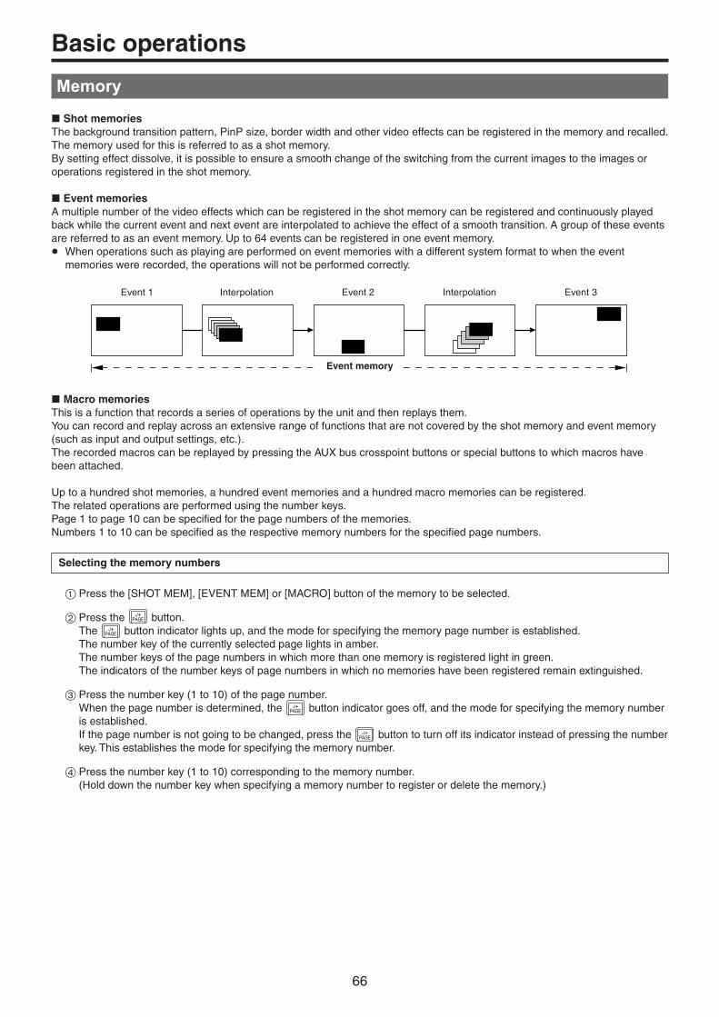
66
Basic operations
Memory
w Shot memoriesThe background transition pattern, PinP size, border width and other video effects can be registered in the memory and recalled. The memory used for this is referred to as a shot memory.By setting effect dissolve, it is possible to ensure a smooth change of the switching from the current images to the images or operations registered in the shot memory.
w Event memoriesA multiple number of the video effects which can be registered in the shot memory can be registered and continuously played back while the current event and next event are interpolated to achieve the effect of a smooth transition. A group of these events are referred to as an event memory. Up to 64 events can be registered in one event memory.pp When operations such as playing are performed on event memories with a different system format to when the event
memories were recorded, the operations will not be performed correctly.
Event 1 Interpolation Event 2
Event memory
Interpolation Event 3
w Macro memoriesThis is a function that records a series of operations by the unit and then replays them.You can record and replay across an extensive range of functions that are not covered by the shot memory and event memory (such as input and output settings, etc.).The recorded macros can be replayed by pressing the AUX bus crosspoint buttons or special buttons to which macros have been attached.
Up to a hundred shot memories, a hundred event memories and a hundred macro memories can be registered.The related operations are performed using the number keys.Page 1 to page 10 can be specified for the page numbers of the memories.Numbers 1 to 10 can be specified as the respective memory numbers for the specified page numbers.
Selecting the memory numbers
1Press the [SHOT MEM], [EVENT MEM] or [MACRO] button of the memory to be selected.
2Press the -/+PAGE button.
The -/+PAGE button indicator lights up, and the mode for specifying the memory page number is established.
The number key of the currently selected page lights in amber. The number keys of the page numbers in which more than one memory is registered light in green. The indicators of the number keys of page numbers in which no memories have been registered remain extinguished.
3Press the number key (1 to 10) of the page number. When the page number is determined, the -/+
PAGE button indicator goes off, and the mode for specifying the memory number is established. If the page number is not going to be changed, press the -/+
PAGE button to turn off its indicator instead of pressing the number key. This establishes the mode for specifying the memory number.
4Press the number key (1 to 10) corresponding to the memory number. (Hold down the number key when specifying a memory number to register or delete the memory.)

67
Basic operations
Memory registration
Applicable bus
Material selection Transition Pattern MenuShot
memory target
Event memory
target
Macro memory
target
ME p PGM/A busp PST/B busp Key Fill busp Key Source bus
p Fader amount p Wipe direction
p BKGD patterns (MIX, WIPE)
p KEY patterns (MIX, WIPE)
p Background
p Key
p Chroma Key
DSK p DSK Fill busp DSK Source bus
p DSK
AUX p AUX bus
CBGD p Color Background —
CLIP p Video Memory— —
MENU Menu operation Each menu— —
XPT XPT selection operation
p XPT— —
OTHER p DISP bus — —
: Valid—: Invalid
Memory recall items
The targets for memory recall can be selected as On (recall target)/Off (not a recall target) in the Target Select 1 and 2 menus.
Target1, 2 Recall target
ME A/B XPT, BKGD, KEY1, KEY2, KEY3
DSK DSK1, DSK2
AUX AUX1, AUX2, AUX3, AUX4
CBGD CBGD1, CBGD2
CLIP CLIP1, CLIP2
pp CLIP is for the event memory only.

68
Basic operations
Storing the settings in the memory (Store)
Images and operations to be registered can be set and then registered in the memories.
STORE
DEL VMEMMACRO
EDIT
SHOTMEM
BKGDPATT
XPTDSBL
TAKEENTER
7NEW
8COPY
9PASTE
4INS
5DEL
6MOD
1<
2>
3REV
0/10<<
.>>
CUNDO
CAMPMEM
CAMCONT
EVENTMEM
KEYPATT
-/+PAGE
RECALL
MEMORY / WIPE PATTERN / 10 KEY
STILL 1 STILL 2 TRIM IN REC
CLIP 1 CLIP 2 TRIM OUT
< > REV
<< >> TRIM OFF PLAY
STOP
1Using the unit, set the images or operations to be kept in the memory. To register event memory, refer to “w Creating a new timeline” in “Editing event memory timelines”.
2Press the [SHOT MEM], [EVENT MEM] or [MACRO] button of the memory in which the images or operations are to be registered. Depending on the operation that was performed last, the [STORE] button, [RECALL] button, [DEL] button or [EDIT] button lights.
3Select the bus (ME, DSK, AUX, CBGD, CLIP, MENU, XPT or OTHER) to be registered in the memory. From the Shot Memory menu (or Event Memory menu), select the Target Select1/2 sub menu, and then select “On”. From the Macro menu, select the Store Select sub menu, and then select “On”. Refer to “Memory registration” and “Selecting the
buses whose settings are to be registered and or played back”.
4Press the [STORE] button. The [STORE] button turns red.
5Press the -/+PAGE button, and press the number key (1 to
10) corresponding to the page number.
6Hold down (for 2 seconds or so) the number key (1 to 10) corresponding to the number of the memory to be registered. When the registration is completed, the number key corresponding to the memory number lights in green.
p The number keys whose indicators are lit in green have memories already registered in them. Delete the memory corresponding to the number key concerned, and register the new memory.
7Repeat the above steps to register other kinds of settings in the memories.
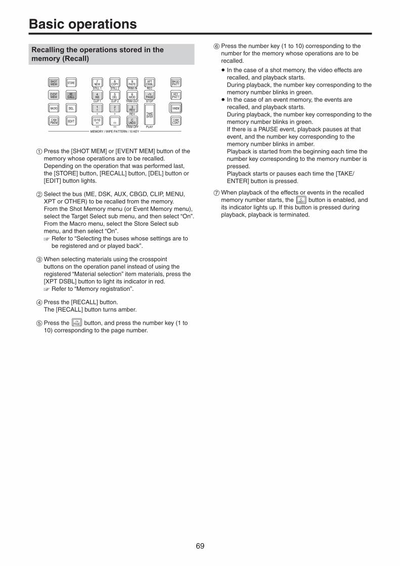
69
Basic operations
Recalling the operations stored in the memory (Recall)
STORE
DEL VMEMMACRO
EDIT
SHOTMEM
BKGDPATT
XPTDSBL
TAKEENTER
7NEW
8COPY
9PASTE
4INS
5DEL
6MOD
1<
2>
3REV
0/10<<
.>>
CUNDO
CAMPMEM
CAMCONT
EVENTMEM
KEYPATT
-/+PAGE
RECALL
MEMORY / WIPE PATTERN / 10 KEY
STILL 1 STILL 2 TRIM IN REC
CLIP 1 CLIP 2 TRIM OUT
< > REV
<< >> TRIM OFF PLAY
STOP
1Press the [SHOT MEM] or [EVENT MEM] button of the memory whose operations are to be recalled. Depending on the operation that was performed last, the [STORE] button, [RECALL] button, [DEL] button or [EDIT] button lights.
2Select the bus (ME, DSK, AUX, CBGD, CLIP, MENU, XPT or OTHER) to be recalled from the memory. From the Shot Memory menu (or Event Memory menu), select the Target Select sub menu, and then select “On”. From the Macro menu, select the Store Select sub menu, and then select “On”. Refer to “Selecting the buses whose settings are to
be registered and or played back”.
3When selecting materials using the crosspoint buttons on the operation panel instead of using the registered “Material selection” item materials, press the [XPT DSBL] button to light its indicator in red. Refer to “Memory registration”.
4Press the [RECALL] button. The [RECALL] button turns amber.
5Press the -/+PAGE button, and press the number key (1 to
10) corresponding to the page number.
6Press the number key (1 to 10) corresponding to the number for the memory whose operations are to be recalled.
p In the case of a shot memory, the video effects are recalled, and playback starts. During playback, the number key corresponding to the memory number blinks in green. p In the case of an event memory, the events are recalled, and playback starts. During playback, the number key corresponding to the memory number blinks in green. If there is a PAUSE event, playback pauses at that event, and the number key corresponding to the memory number blinks in amber. Playback is started from the beginning each time the number key corresponding to the memory number is pressed. Playback starts or pauses each time the [TAKE/ENTER] button is pressed.
7When playback of the effects or events in the recalled memory number starts, the C
UNDO button is enabled, and its indicator lights up. If this button is pressed during playback, playback is terminated.

70
Basic operations
Deleting the operations stored in the memory (Delete)
STORE
DEL VMEMMACRO
EDIT
SHOTMEM
BKGDPATT
XPTDSBL
TAKEENTER
7NEW
8COPY
9PASTE
4INS
5DEL
6MOD
1<
2>
3REV
0/10<<
.>>
CUNDO
CAMPMEM
CAMCONT
EVENTMEM
KEYPATT
-/+PAGE
RECALL
MEMORY / WIPE PATTERN / 10 KEY
STILL 1 STILL 2 TRIM IN REC
CLIP 1 CLIP 2 TRIM OUT
< > REV
<< >> TRIM OFF PLAY
STOP
1Press the [SHOT MEM] or [EVENT MEM] button of the memory whose operations are to be deleted to select the memory. The selected button lights in amber. Depending on the operation that was performed last, the [STORE] button, [RECALL] button, [DEL] button or [EDIT] button lights.
2Press the [DEL] button. The [DEL] button lights in red. The button of the number key containing the stored operations lights in green.
p To change a page number, press the -/+PAGE button, and
press the number key (1 to 10) corresponding to the page number. Next, press the number key (1 to 10) corresponding to the number of the memory whose operations are to be deleted.
3Hold down (for 2 seconds or so) the number key (1 to 10) corresponding to the number of the memory whose operations are to be deleted. The button of the pressed number key goes off.

71
Basic operations
Selecting the buses whose settings are to be registered and or played back
Bus selection when registering/playing back memories
Select the bus used for registering event memories, shot memories and macro memories.
1Press the SHOTEVENT button to display the Event Memory menu (Shot Memory menu or Macro menu).
2Use [F1] to display the Target Select1, 2 sub menu.
3Use [F2] to [F5] to set the items to be saved to “On”.
Event Memory menu:
Shot Memory menu:
Macro menu:
On The bus settings are registered in the memories.
Off The bus settings are not registered in the memories.
<Example of memory information display>Page: 1 (1 to 10)
Registering the material selection items
Set whether or not to register the “Material selection” items of the buses. Refer to “Memory registration”.

72
Basic operations
Setting effect dissolve (shot memory)
Switching from the current image to the image or operation stored in the shot memory can be performed smoothly.
1Press the SHOTEVENT button to display the Shot Memory menu.
2Use [F1] to display the Path sub menu.
3Use [F2] to set the effect used for switching the images using the Effect item.
Cut The images are switched using the cut effect.
Dissolve The images are switched using the dissolve effect.
p The dissolve effect duration is set in the Effect Dissolve sub menu which is selected in the Time menu.
4Use [F3] to select the effect used for switching the colors using the Hue Path item. The following colors are targeted by Hue.
p Colors of the color background p Colors of the borders p Colors of the edges p Colors of the fill matte
Short The colors are changed toward less hue on the vectorscope.
Long The colors are changed toward more hue on the vectorscope.
CW The Hue is changed clockwise on the vectorscope.
CCW The Hue is changed counterclockwise on the vectorscope.
p Pressed number keys blink in green while the operation switching is underway.
pWhen the operation switching has been completed, the pressed number key lights in amber. pWhen the Effect item is changed from “Dissolve” to “Cut” while operation is being switched, the dissolve effect is released, and the images are switched to the images of the selected shot memory in an instant. p During the operation switching, the operation of the fader lever is canceled. p There are cases when it is not possible to recall other memory operations during operation switching:· Recalling another shot memory while a shot memory is
operating· Recalling another event memory while an event memory is operating
p It is possible to recall a shot memory while an event memory is operating or to recall an event memory while a shot memory is operating, but if there is conflict with the buses or materials played back by the event memory and shot memory, playback occurs after switching to the memory recalled last.

73
Basic operations
Editing event memory timelines
Insertion or modification of the events can be edited on the timelines.
w TimelineA timeline is a succession of events in the event memories which have been joined together on the time axis.
w Event points and edit pointsOn a timeline, the position where an event has been registered is called the event point, and the event currently being edited is called the current event memory.When there is an edit point between one event point and another, the event point before the edit point serves as the current event memory.(Event “n” in the figure below)
<Event points and edit points>
Edit point
Event “n”
Event “n”+1
Event “n”+2
w Event duration and total durationThe length of time as far as the next event is called the event duration. The total of all the event durations is called the total duration.The present point in time on the timeline is called the current time.
<How times are referred to>
1s00f 1s00f 1s00f
Event duration
The event stops.The event progresses in this direction.
Current time
Total duration
Event 1
Event 2
Event 3
Timeline editing flow
w Modifying registered event memories
1Press the [EVENT MEM] button and light its indicator.
STORE
DEL VMEMMACRO
EDIT
SHOTMEM
BKGDPATT
XPTDSBL
TAKEENTER
7NEW
8COPY
9PASTE
4INS
5DEL
6MOD
1<
2>
3REV
0/10<<
.>>
CUNDO
CAMPMEM
CAMCONT
EVENTMEM
KEYPATT
-/+PAGE
RECALL
MENU
MEMORY / WIPE PATTERN / 10 KEY
STILL 1 STILL 2 TRIM IN REC
CLIP 1 CLIP 2 TRIM OUT
< > REV
<< >> TRIM OFF PLAY
STOP
DISPLAY
[EVENT MEM] button
2Press the [RECALL] button to light its indicator, and use the -/+
PAGE button and number keys (1 to 10) to select the event memory to be modified. Refer to “Recalling the operations stored in the
memory (Recall)”.
3Press the [EDIT] button to establish the editing mode. (At this point, the timeline of the selected event memory is copied into the work area.) The timeline appears on the built-in display, and events can be inserted or modified.
4Edit the timeline, and check what has been edited. Refer to the operations described later.
5Register the event memory which has been modified. Refer to “Storing the settings in the memory (Store)”.
w Creating a new timeline
When this operation is performed, the timeline currently in the work area is deleted.If it is required, register it in the event memory.
1Press the [EVENT MEM] button and light its indicator.
2Press the [EDIT] button to light its indicator, and press 7
NEW .
3Create the new timeline. Refer to the operations described later.
4Register the event memory which has just been created. Refer to “Storing the settings in the memory (Store)”.
The timeline is edited in the work area.After editing is completed, be absolutely sure to register which has been edited.
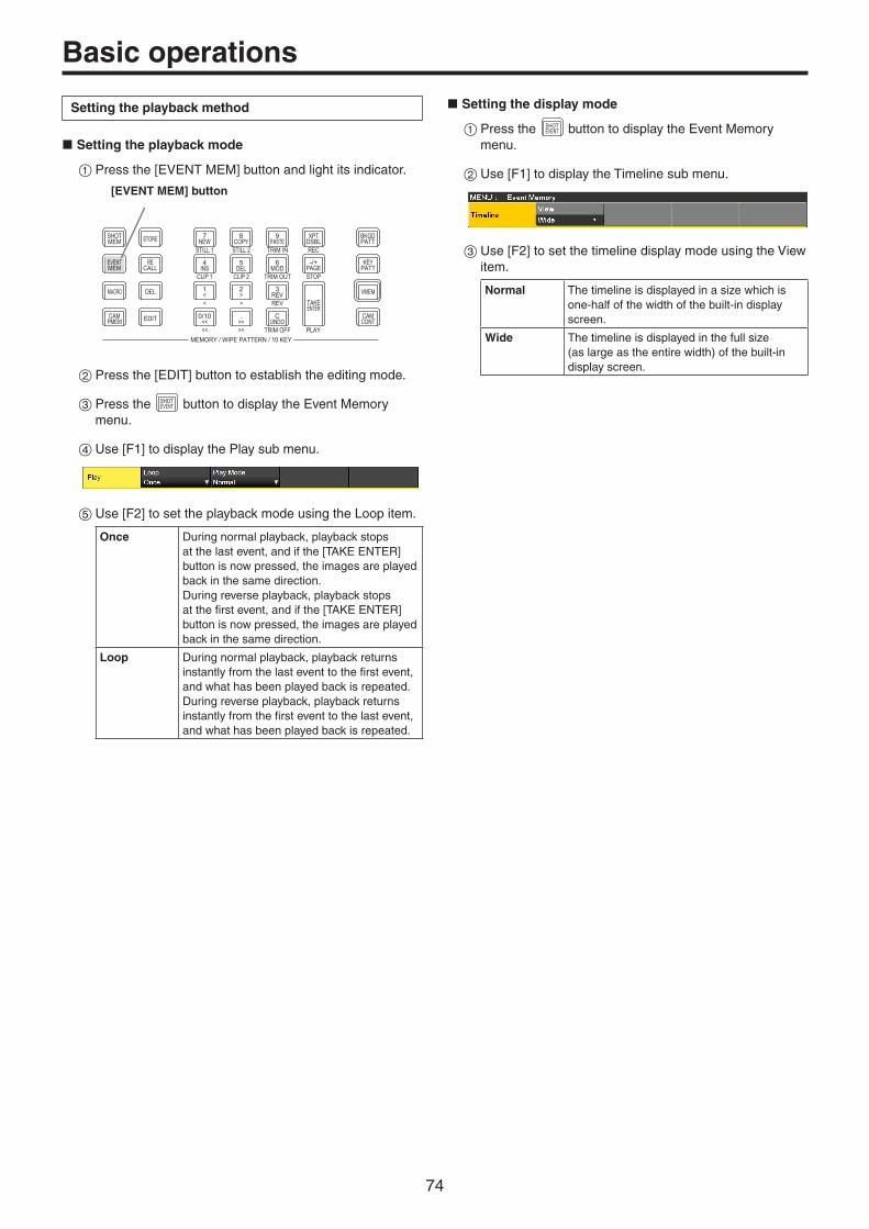
74
Basic operations
Setting the playback method
w Setting the playback mode
1Press the [EVENT MEM] button and light its indicator.
STORE
DEL VMEMMACRO
EDIT
SHOTMEM
BKGDPATT
XPTDSBL
TAKEENTER
7NEW
8COPY
9PASTE
4INS
5DEL
6MOD
1<
2>
3REV
0/10<<
.>>
CUNDO
CAMPMEM
CAMCONT
EVENTMEM
KEYPATT
-/+PAGE
RECALL
MENU
MEMORY / WIPE PATTERN / 10 KEY
STILL 1 STILL 2 TRIM IN REC
CLIP 1 CLIP 2 TRIM OUT
< > REV
<< >> TRIM OFF PLAY
STOP
DISPLAY
[EVENT MEM] button
2Press the [EDIT] button to establish the editing mode.
3Press the SHOTEVENT button to display the Event Memory
menu.
4Use [F1] to display the Play sub menu.
5Use [F2] to set the playback mode using the Loop item.
Once During normal playback, playback stops at the last event, and if the [TAKE ENTER] button is now pressed, the images are played back in the same direction.During reverse playback, playback stops at the first event, and if the [TAKE ENTER] button is now pressed, the images are played back in the same direction.
Loop During normal playback, playback returns instantly from the last event to the first event, and what has been played back is repeated.During reverse playback, playback returns instantly from the first event to the last event, and what has been played back is repeated.
w Setting the display mode
1Press the SHOTEVENT button to display the Event Memory
menu.
2Use [F1] to display the Timeline sub menu.
3Use [F2] to set the timeline display mode using the View item.
Normal The timeline is displayed in a size which is one-half of the width of the built-in display screen.
Wide The timeline is displayed in the full size (as large as the entire width) of the built-in display screen.

75
Basic operations
<Timeline displays (on the built-in display)>
A green “” below the timeline indicates an event point.
A “||” indicates that “PAUSE” has been set for an event point.
If an edit point is over an event point, “” for the event point is indicated in amber.
When “CLIP” (Clip1, Clip2) has been registered in an event, “ ” appears above the event point.
Similarly, when “GPI-Out” (GPI-O1 to GPI-O19) has been registered in an event, “ ” appears above the event point.
The timeline axis is indicated in green from the start event to the end event.
During playback, the part from the beginning to the current position is indicated in yellow.
Similarly, during reverse playback, the part from the end to the current position is indicated in yellow.
w Number key operations
VMEM
BKGDPATT
XPTDSBL
TAKEENTER
7NEW
8COPY
9PASTE
4INS
5DEL
6MOD
1<
2>
3REV
0/10<<
.>>
CUNDO
CAMCONT
KEYPATT
-/+PAGE
MEMORY / WIPE PATTERN / 10 KEY
STILL 1 STILL 2 TRIM IN REC
CLIP 1 CLIP 2 TRIM OUT
< > REV
<< >> TRIM OFF PLAY
STOP
7NEW
STILL 1
Creates a new timeline.
8COPY
STILL 2
Copies events.An event is not copied if an edit point is not over the event.
9PASTE
TRIM IN
Pastes the copied events.If the edit point is an event point, the event is inserted after the event point.If the edit point is at any midway position in an event, the event is inserted at the edit point.
4INS
CLIP 1
Inserts events.If the edit point is an event point, the event is inserted after the event point.If the edit point is at any midway position in an event, the event is inserted at the edit point.
5DEL
CLIP 2
Deletes events.
6MOD
TRIM OUT
Modifies events.This key cannot be operated if the edit point is not over the event point.
0/10<<<<
Moves to the start event point.
.>>>>
Moves to the end event point.
2>>
Moves to the next event point.
1<<
Moves to the previous event point.
3REVREV
Reverses the playback direction (event numbers are put in their reverse sequence).
CUNDO
TRIM OFF
Undoes the editing operation of the event.When the button is pressed, the operation performed last is canceled.
TAKEENTER
PLAY
Plays back events.When this button is operational, its indicator lights in amber.Each time it is pressed, operation is switched between playback and pause.During playback, its indicator blinks in green; during pause, it blinks in amber.

76
Basic operations
Inserting events (Insert)
The current setting status can be inserted as an event after the current event memory.When an event is inserted, the numbers of the events after the current event memory are each moved up by one.
1Use 0/10<< , 1
< , 2> and .
>> to select the event point (current event memory) which is to be inserted. To insert the event at a midway point of an event, play back the event to the place where the event is to be inserted, and stop the edit point.
2Operate the panel, and create the event.
3Press 4INS to insert the created event.
To cancel the event insertion, press the CUNDO button.
pWhen the number of events on the timeline has reached 64, no further events can be inserted. pWhen the edit point is over the event point, the newly created event is inserted with the same duration as the current event memory.
p If the edit point is between one event point and another, the current event memory is split at the edit point position, and the newly created event is inserted.
pWhen registering “CLIP” (Clip1, Clip2) to event memory, place Current time for Clip1 (or Clip2) at the beginning (from the Video Memory2 sub menu, press [F2] (LEAD)). Some clips might not play back.
Modifying events (Modify)
Already registered events can be modified.
1Use 0/10<< , 1
< , 2> and .
>> to select the event point of the event to be modified.
2Operate the panel, and modify the event.
3Press 6MOD to set the modified details.
To cancel the event modification, press the CUNDO button.
Copying events (Copy)
Already registered events can be copied.
1Use 0/10<< , 1
< , 2> and .
>> to select the event point of the event to be copied.
2Press 8COPY to copy the event.
Pasting events (Paste)
Copied events can be pasted.
1Use 0/10<< , 1
< , 2> and .
>> to select the event point where the copied event is to be inserted. To insert the copied event between one event point and another, play back the event to the place where the copied event is to be inserted, and stop the playback.
2Press 9PASTE to paste the copied event.
To cancel the event pasting, press the CUNDO button.
pWhen the number of events on the timeline has reached 64, no further events can be inserted. pWhen the edit point is over an event point, the copied event is inserted with the same duration as the current event memory. p If the edit point is between one event point and another, the current event memory is split at the edit point position, and the copied event is inserted.
Deleting events (Delete)
Already registered events can be deleted.
1Use 0/10<< , 1
< , 2> and .
>> to select the event point of the event to be deleted.
2Press 5DEL to delete the event.
To cancel the event deletion, press the CUNDO button.
p Even if the edit point is midway through an event, the current event memory will be deleted.
Undoing what has been edited (Undo)
When the CUNDO button is pressed, the operation performed last
is canceled.
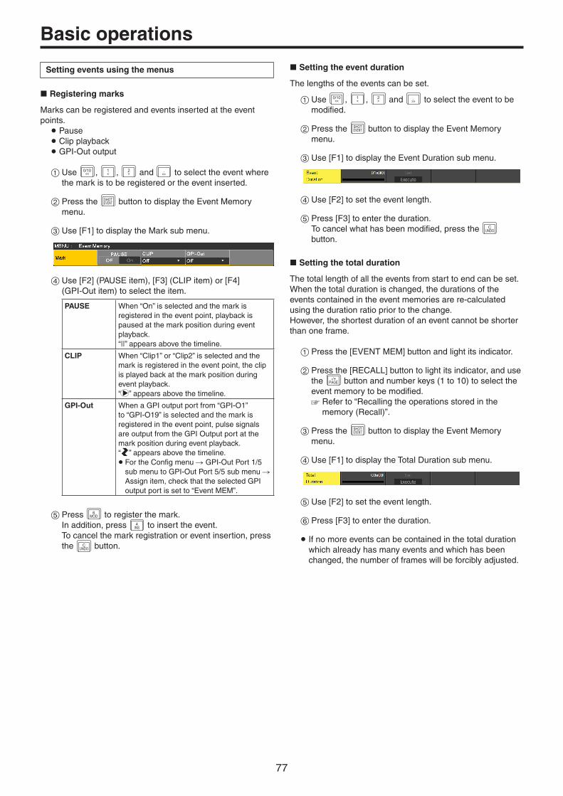
77
Basic operations
Setting events using the menus
w Registering marks
Marks can be registered and events inserted at the event points.
p Pause p Clip playback p GPI-Out output
1Use 0/10<< , 1
< , 2> and .
>> to select the event where the mark is to be registered or the event inserted.
2Press the SHOTEVENT button to display the Event Memory
menu.
3Use [F1] to display the Mark sub menu.
4Use [F2] (PAUSE item), [F3] (CLIP item) or [F4] (GPI-Out item) to select the item.
PAUSE When “On” is selected and the mark is registered in the event point, playback is paused at the mark position during event playback.“||” appears above the timeline.
CLIP When “Clip1” or “Clip2” is selected and the mark is registered in the event point, the clip is played back at the mark position during event playback.“ ” appears above the timeline.
GPI-Out When a GPI output port from “GPI-O1” to “GPI-O19” is selected and the mark is registered in the event point, pulse signals are output from the GPI Output port at the mark position during event playback.“ ” appears above the timeline.p For the Config menu GPI-Out Port 1/5
sub menu to GPI-Out Port 5/5 sub menu Assign item, check that the selected GPI output port is set to “Event MEM”.
5Press 6MOD to register the mark.
In addition, press 4INS to insert the event.
To cancel the mark registration or event insertion, press the C
UNDO button.
w Setting the event duration
The lengths of the events can be set.
1Use 0/10<< , 1
< , 2> and .
>> to select the event to be modified.
2Press the SHOTEVENT button to display the Event Memory
menu.
3Use [F1] to display the Event Duration sub menu.
4Use [F2] to set the event length.
5Press [F3] to enter the duration. To cancel what has been modified, press the C
UNDO button.
w Setting the total duration
The total length of all the events from start to end can be set.When the total duration is changed, the durations of the events contained in the event memories are re-calculated using the duration ratio prior to the change.However, the shortest duration of an event cannot be shorter than one frame.
1Press the [EVENT MEM] button and light its indicator.
2Press the [RECALL] button to light its indicator, and use the -/+
PAGE button and number keys (1 to 10) to select the event memory to be modified. Refer to “Recalling the operations stored in the
memory (Recall)”.
3Press the SHOTEVENT button to display the Event Memory
menu.
4Use [F1] to display the Total Duration sub menu.
5Use [F2] to set the event length.
6Press [F3] to enter the duration.
p If no more events can be contained in the total duration which already has many events and which has been changed, the number of frames will be forcibly adjusted.

78
Basic operations
w Setting the event switching effect (Path)
Switching from one event to another (bus switching) can be accomplished smoothly.
1Press the SHOTEVENT button to light its indicator, and display
the Event Memory menu.
2Use [F1] to display the Path sub menu.
3Use [F2] and the Trans Path item to set how transitions to the next event are performed. The following transitions are available:
pWidth of the borders p Soft effect of the borders p Positions of the images p Trimming values
Linear The switching from one image to another is interpolated linearly.
Spline The switching from one image to another is interpolated over a smooth curve (a cubic function curve).
Step The parameters are updated when the events are passed through.
4Use [F3] to select the effect when the colors are switched using the Hue Path item. The following hues are targeted.
p Colors of the color background p Colors of the borders p Colors of the edges p Colors of the fill matte
Short The colors are changed toward less hue on the vectorscope.
Long The colors are changed toward more hue on the vectorscope.
CW The Hue is changed clockwise on the vectorscope.
CCW The Hue is changed counterclockwise on the vectorscope.
Step The color changes are updated when an event is passed through.
Macro memory settings
Recording non-operation periods
1Press the VMEMMACRO button to light its indicator, and display
the Macro menu.
2Use [F1] to display the Insert Delay sub menu.
3Use [F2] to set the time of the non-operation period in the Time item.
4Use [F3] to save the time set in Step 3.
Assigning macro memories
You can assign registered macro memories to the AUX bus crosspoint buttons.
1Press the VMEMMACRO button to light its indicator, and display
the Macro menu.
2Use [F1] to display the Macro Assign1/6 to 6/6 sub menu.
3Use [F2] to [F5] in each of the sub menus to set the macro memories assigned to each crosspoint in the XPT1 to 24 items.
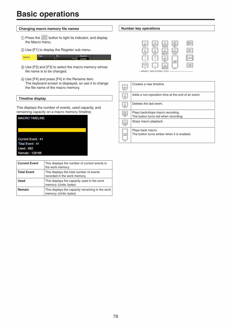
79
Basic operations
Changing macro memory file names
1Press the VMEMMACRO button to light its indicator, and display
the Macro menu.
2Use [F1] to display the Register sub menu.
3Use [F2] and [F3] to select the macro memory whose file name is to be changed.
4Use [F4] and press [F4] in the Rename item. The keyboard screen is displayed, so use it to change the file name of the macro memory.
Timeline display
This displays the number of events, used capacity, and remaining capacity on a macro memory timeline.
Current Event This displays the number of current events in the work memory.
Total Event This displays the total number of events recorded in the work memory.
Used This displays the capacity used in the work memory. (Units: bytes)
Remain This displays the capacity remaining in the work memory. (Units: bytes)
Number key operations
VMEM
BKGDPATT
XPTDSBL
TAKEENTER
7NEW
8COPY
9PASTE
4INS
5DEL
6MOD
1<
2>
3REV
0/10<<
.>>
CUNDO
CAMCONT
KEYPATT
-/+PAGE
MEMORY / WIPE PATTERN / 10 KEY
STILL 1 STILL 2 TRIM IN REC
CLIP 1 CLIP 2 TRIM OUT
< > REV
<< >> TRIM OFF PLAY
STOP
7NEW
STILL 1
Creates a new timeline.
4INS
CLIP 1
Adds a non-operation time at the end of an event.
5DEL
CLIP 2
Deletes the last event.
XPTDSBLREC
Plays back/stops macro recording.The button turns red when recording.
-/+PAGESTOP
Stops macro playback.
TAKEENTER
PLAY
Plays back macro.The button turns amber when it is enabled.
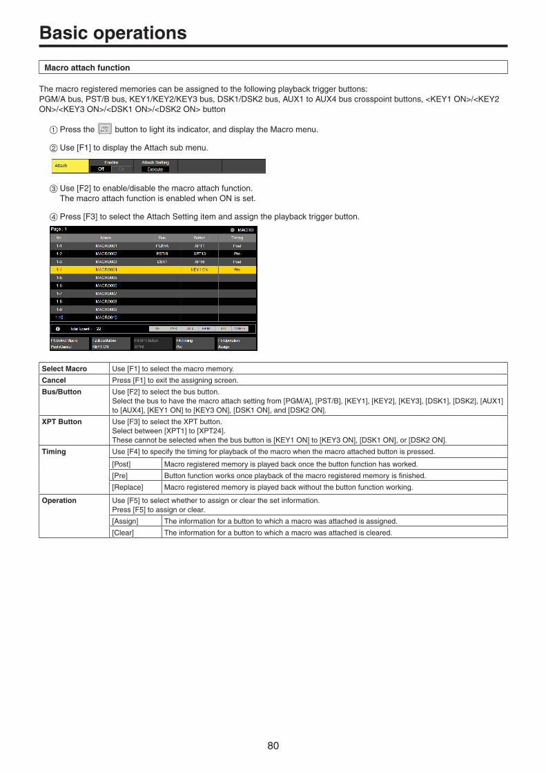
80
Basic operations
Macro attach function
The macro registered memories can be assigned to the following playback trigger buttons:PGM/A bus, PST/B bus, KEY1/KEY2/KEY3 bus, DSK1/DSK2 bus, AUX1 to AUX4 bus crosspoint buttons, <KEY1 ON>/<KEY2 ON>/<KEY3 ON>/<DSK1 ON>/<DSK2 ON> button
1Press the VMEMMACRO button to light its indicator, and display the Macro menu.
2Use [F1] to display the Attach sub menu.
3Use [F2] to enable/disable the macro attach function. The macro attach function is enabled when ON is set.
4Press [F3] to select the Attach Setting item and assign the playback trigger button.
Select Macro Use [F1] to select the macro memory.
Cancel Press [F1] to exit the assigning screen.
Bus/Button Use [F2] to select the bus button.Select the bus to have the macro attach setting from [PGM/A], [PST/B], [KEY1], [KEY2], [KEY3], [DSK1], [DSK2], [AUX1] to [AUX4], [KEY1 ON] to [KEY3 ON], [DSK1 ON], and [DSK2 ON].
XPT Button Use [F3] to select the XPT button.Select between [XPT1] to [XPT24].These cannot be selected when the bus button is [KEY1 ON] to [KEY3 ON], [DSK1 ON], or [DSK2 ON].
Timing Use [F4] to specify the timing for playback of the macro when the macro attached button is pressed.
[Post] Macro registered memory is played back once the button function has worked.
[Pre] Button function works once playback of the macro registered memory is finished.
[Replace] Macro registered memory is played back without the button function working.
Operation Use [F5] to select whether to assign or clear the set information.Press [F5] to assign or clear.
[Assign] The information for a button to which a macro was attached is assigned.
[Clear] The information for a button to which a macro was attached is cleared.
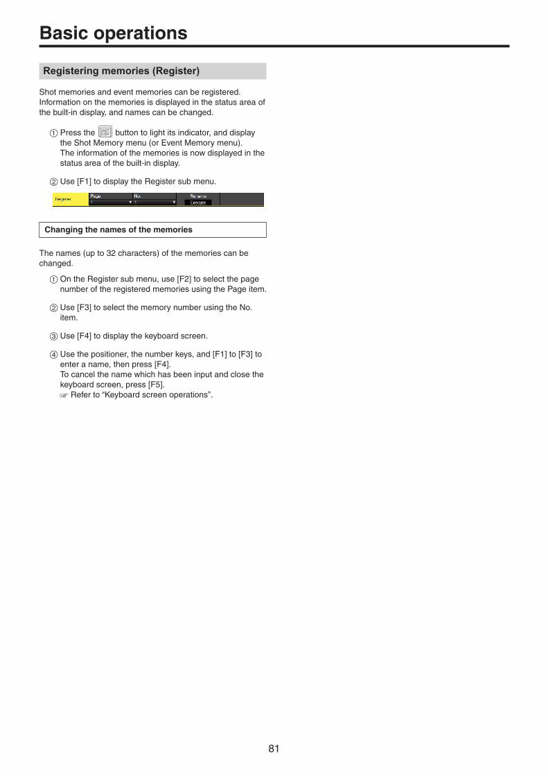
81
Basic operations
Registering memories (Register)
Shot memories and event memories can be registered.Information on the memories is displayed in the status area of the built-in display, and names can be changed.
1Press the SHOTEVENT button to light its indicator, and display
the Shot Memory menu (or Event Memory menu). The information of the memories is now displayed in the status area of the built-in display.
2Use [F1] to display the Register sub menu.
Changing the names of the memories
The names (up to 32 characters) of the memories can be changed.
1On the Register sub menu, use [F2] to select the page number of the registered memories using the Page item.
2Use [F3] to select the memory number using the No. item.
3Use [F4] to display the keyboard screen.
4Use the positioner, the number keys, and [F1] to [F3] to enter a name, then press [F4]. To cancel the name which has been input and close the keyboard screen, press [F5]. Refer to “Keyboard screen operations”.
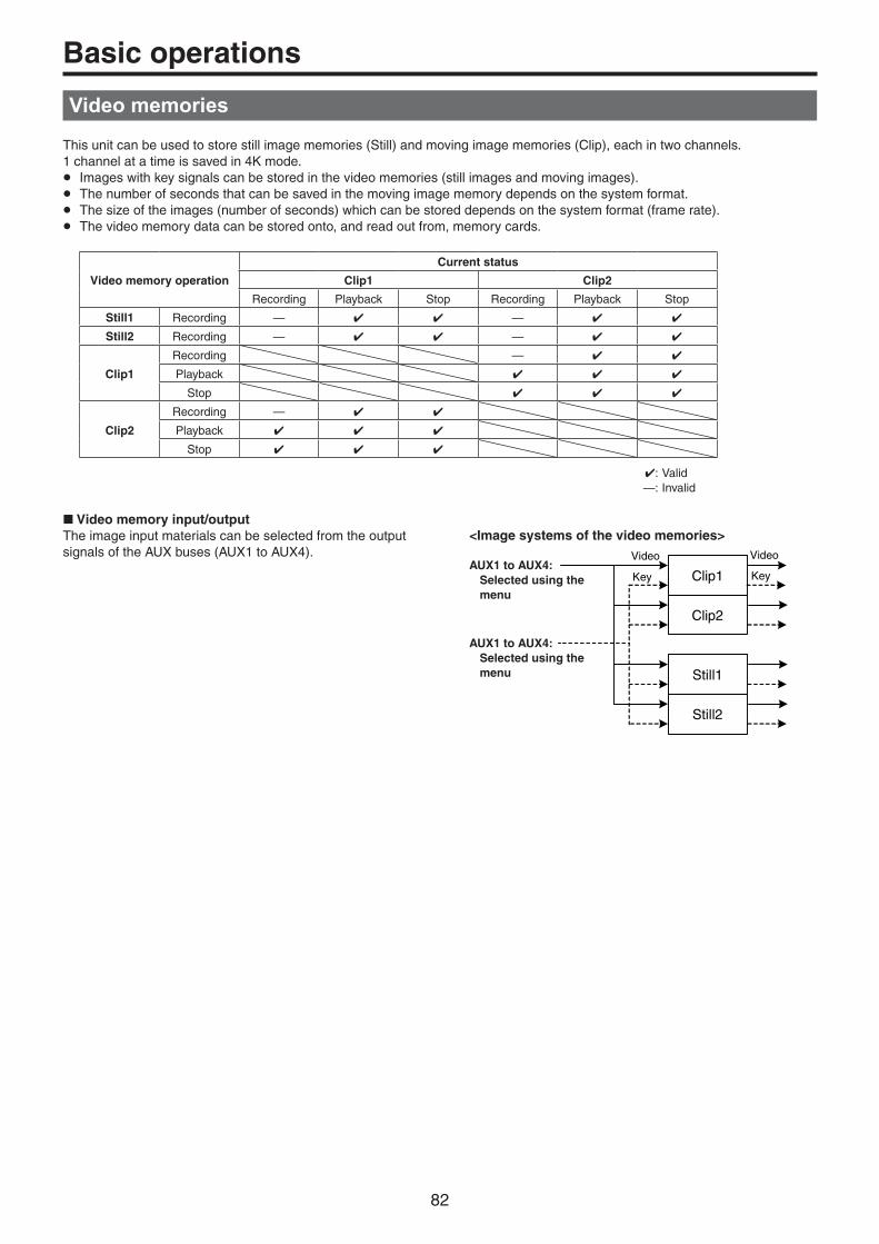
82
Basic operations
Video memories
This unit can be used to store still image memories (Still) and moving image memories (Clip), each in two channels.1 channel at a time is saved in 4K mode.pp Images with key signals can be stored in the video memories (still images and moving images).pp The number of seconds that can be saved in the moving image memory depends on the system format.pp The size of the images (number of seconds) which can be stored depends on the system format (frame rate).pp The video memory data can be stored onto, and read out from, memory cards.
Video memory operation
Current status
Clip1 Clip2
Recording Playback Stop Recording Playback Stop
Still1 Recording — —
Still2 Recording — —
Clip1
Recording —
Playback
Stop
Clip2
Recording —
Playback
Stop
: Valid —: Invalid
w Video memory input/outputThe image input materials can be selected from the output signals of the AUX buses (AUX1 to AUX4).
<Image systems of the video memories>
Still2
Still1
Clip2
Clip1 Key
Video
Key
Video
AUX1 to AUX4: Selected using the
menu
AUX1 to AUX4: Selected using the
menu

83
Basic operations
Recording still images (Still)
1Press the VMEMMACRO button to light its indicator, and display
the Video Memory menu.
2Use [F1] to display the Video Memory1 sub menu.
3Use [F2] to select “Still1” or “Still2” using the Select item.
p Only Still1 can be selected in the 4K mode.
4Use [F1] to display the Rec2 sub menu.
5Use [F2] to set the images to appear on the built-in display using the Preview item.
On The image appearing on the built-in display is forcibly switched to the image to be recorded (AUX1 to AUX4 selected using the VMEM Video item) instead of the material selected by the DISP bus.
Off The image source selected by the DISP bus is displayed as a preview.
When “On” is selected for the Preview item, be aware that the following operations will occur:
p The DISP button will link with the AUX bus selection button (AUX BUS DELEGATION) of AUX1 to AUX4 selected in the VMEM Video item, which will light or turn off the buttons. p If the material of the DISP bus is changed, the materials of the DISP bus and the selected AUX bus change at the same time. Similarly, if the material of the selected AUX bus is changed, the material of the DISP bus changes at the same time.
6Use [F2] and [F3] of Rec1 to set the images to be recorded in the video memory in the VMEM Video item.
AUX1 to AUX4
The output signals of the AUX buses (AUX1 to AUX4) are recorded as the material.
7Use [F4] of Rec2 to set the review display in the Review item.
On After the images have been recorded, the images of the video memory recorded in the AUX bus are displayed (for 2 seconds or so).
Off The review display is not shown.
8Use [F1] to display the Video Memory1 sub menu.
9As soon as [F3] (Rec) is pressed, the still images are recorded.
p If the [VMEM] button on the right of the number keys is pressed and the video memory operation mode has been established, the operation of this button is linked with the [XPT/DSBL] button among the number keys. pWhen the recording of the still images is completed, thumbnails of the still images are displayed in the thumbnail screen.

84
Basic operations
Recording moving images (Clip)
1Press the VMEMMACRO button to light its indicator, and display
the Video Memory menu.
2Use [F1] to display the Video Memory1 sub menu.
3Use [F2] to select “Clip1” or “Clip2” using the Select item.
p Only Clip1 can be selected in the 4K mode.
4Use [F1] to display the Rec2 sub menu.
5Use [F2] to set the images to appear on the built-in display using the Preview item.
On The image appearing on the built-in display is forcibly switched to the image to be recorded (AUX1 to AUX4 selected using the VMEM Video item) instead of the material selected by the DISP bus.
Off The image source selected by the DISP bus is displayed as a preview.
When “On” is selected for the Preview item, be aware that the following operations will occur:
p The DISP button will link with the AUX bus selection button (AUX BUS DELEGATION) of AUX1 to AUX4 selected in the VMEM Video item, which will light or turn off the buttons. p If the material of the DISP bus is changed, the materials of the DISP bus and the selected AUX bus change at the same time. Similarly, if the material of the selected AUX bus is changed, the material of the DISP bus changes at the same time.
6Use [F2] and [F3] of Rec1 to set the images to be recorded in the video memory in the VMEM Video item.
AUX1 to AUX4
The output signals of the AUX buses (AUX1 to AUX4) are recorded as the material.
7Use [F4] of Rec2 to set the review display in the Review item.
On After the images have been recorded, the images of the video memory recorded in the AUX bus are displayed (up to 4 seconds).
Off The review display is not shown.
8Use [F1] to display the Rec3 sub menu.
9 Use [F2] to select the recording repeat setting using the Loop item.
On The recording of the images is continued until the stop operation is performed. If either of the following operations is performed while recording is in progress, the images are recorded up to the last frame, after which recording stops.p When “Off” is selected as the Loop item
setting.p When [Stop] ([F5] of Video Memory sub
menu) is pressed.
Off Images are recorded up to the maximum recording time (set using the Limit items), after which recording stops automatically.
Use [F3] to set the quality of the images to be recorded using the Quality item.
Standard Standard image quality
High High image quality
The maximum recording time depends on the video format.
Standard High
2160/59.94p 15 seconds High mode will be half the Standard mode.
2160/50p 18 seconds
2160/29.97p 30 seconds
2160/25p 36 seconds
2160/23.98p, 24p 37.5 seconds
1080/59.94p 60 seconds
1080/50p 72 seconds
1080/29.97psf 120 seconds
1080/25psf 144 seconds
1080/23.98psf, 24psf 150 seconds
1080/59.94i 120 seconds
1080/50i 144 seconds
720/59.94p 120 seconds
720/50p 144 seconds

85
Basic operations
Use [F1] to set the maximum recording time using the Limit item.
Use [F1] to display the Play Mode2 sub menu.
Use [F4] to set the sound to be recorded with the Audio item.
> Use [F1] to display the Video Memory1 sub menu.
As soon as [F3] (Rec) is pressed, the recording of the moving images starts.
When [F5] (Stop) is pressed, the recording of the moving images is stopped.
p If the [VMEM] button on the right of the number keys is pressed and the video memory operation mode has been established, the operation of this button is linked with the -/+
PAGE button among the number keys. p Thumbnails of moving images are displayed on the thumbnail screen. While the thumbnails are displayed, the following information is also displayed on the thumbnail screen.
Current playback position (time), IN point position, OUT point position
pWith the moving images on which the key signals are recorded, a white “” mark is displayed for the thumbnail icons. p The recording time is displayed in the Total Time item of the Video Memory3 sub menu. However, if trimming has been performed, the time from the IN point to the OUT point after trimming is displayed. Also, “On” is displayed for the Key item when the key signals have been recorded.
Saving to the internal storage
Data for images stored in the video memory can be retained even when the power is turned off, by saving them in the internal storage area.Whether to automatically save the image data stored in the video memory when the data is transferred from the AUX bus or to manually save them must be set.
pp If power to the unit is turned off when the saving of data has not finished, video memory data will be lost.pp Video memory data that has been saved is always
restored when the power is turned on.pp If the unit is initialized, video memory that has been
saved to internal storage will be lost.
Notes
1Press the VMEMMACRO button to light its indicator, and display
the Video Memory menu.
2Use [F1] to display the Memory sub menu.
3Use [F2] to select the saving method using the Mode item.
Auto Automatic saving
Manual Manual saving
4Use [F3] to select the video memory for saving data in the internal storage area using the Select item. If “All” is selected, all video memory will be saved. Video memory that has finished being recorded is saved to the internal storage area.
5Press the [F5] (Save) to save data in the internal storage area.
p [F3] (Select) and [F5] (Save) are enabled when “Manual” is selected for the Mode item. pWhen “Auto” is selected for the Mode item, if video memory recording is stopped, the video memory is saved to the internal storage area immediately after recording stops. However, if the power is cut off during recording, the video memories will not be saved in the internal storage area.

86
Basic operations
Playing back moving images (Clip)
Establishing the playback mode
1Press the VMEMMACRO button to light its indicator, and display
the Video Memory menu.
2Use [F1] to display the Play Mode1 sub menu (or Play Mode2 sub menu).
3Use [F2] to select the playback mode using the Mode item.
Lead Operation returns to the start frame after playback.
Last Operation stops at the end frame after playback.
Loop The end frame and start frame are joined together and played back repeatedly.
4Use [F3] to select reverse playback using the Reverse item.
On The moving images are played back in the reverse direction.
Off The moving images are played back in the forward direction.
pWhen the [VMEM] button on the right of the number key is pressed and the video memory operation mode has been established, the operation of this button is linked with the 3
REV button among the number keys.
5Use [F4] to select the speed for variable speed playback using the Variable item.
Speeds which can be selected: 1, 2, 4, 8, 1/2, 1/4, 1/8
6Use [F5] to select the image when operation is stopped using the Freeze item.
Frame Stops at the frame image.
Field Stops at the field image.
p Depending on the video format, some formats cannot be selected.
7Use [F1] to display the Play Mode2 sub menu.
8Use [F2] to set the control button used for playing back moving images in tandem with the transition operation. Use [F2] to set the Clip playback start button.
Off Playback is not performed in tandem with the transition operation.
AUTO The playback of the moving images is started in tandem with the operation of the [AUTO] button.
KEY1 ON The playback of the moving images is started in tandem with the operation of the [KEY1 ON] button.
KEY2 ON The playback of the moving images is started in tandem with the operation of the [KEY2 ON] button.
KEY3 ON The playback of the moving images is started in tandem with the operation of the [KEY3 ON] button.
DSK1 ON The playback of the moving images is started in tandem with the operation of the [DSK1 ON] button.
DSK2 ON The playback of the moving images is started in tandem with the operation of the [DSK2 ON] button.
FTB ON The playback of the moving images is started in tandem with the operation of the [FTB ON] button.
Fader Playback of the moving images is started in tandem with the operation of the fader.
Playing back the moving images
1Press the VMEMMACRO button to light its indicator, and display
the Video Memory menu.
2Use [F1] to display the Video Memory1 sub menu.
3Use [F2] to select Clip1 or Clip2 using the Select item.
4When [F4] (Play) is pressed, playback of the moving images is started.
pWhen the [VMEM] button on the right of the number key is pressed and the video memory operation mode has been established, the operation of this button is linked with the [TAKE/ENTER] button among the number keys.
p The current playback position (time) is displayed for the Current Time item on the Video Memory3 sub menu.
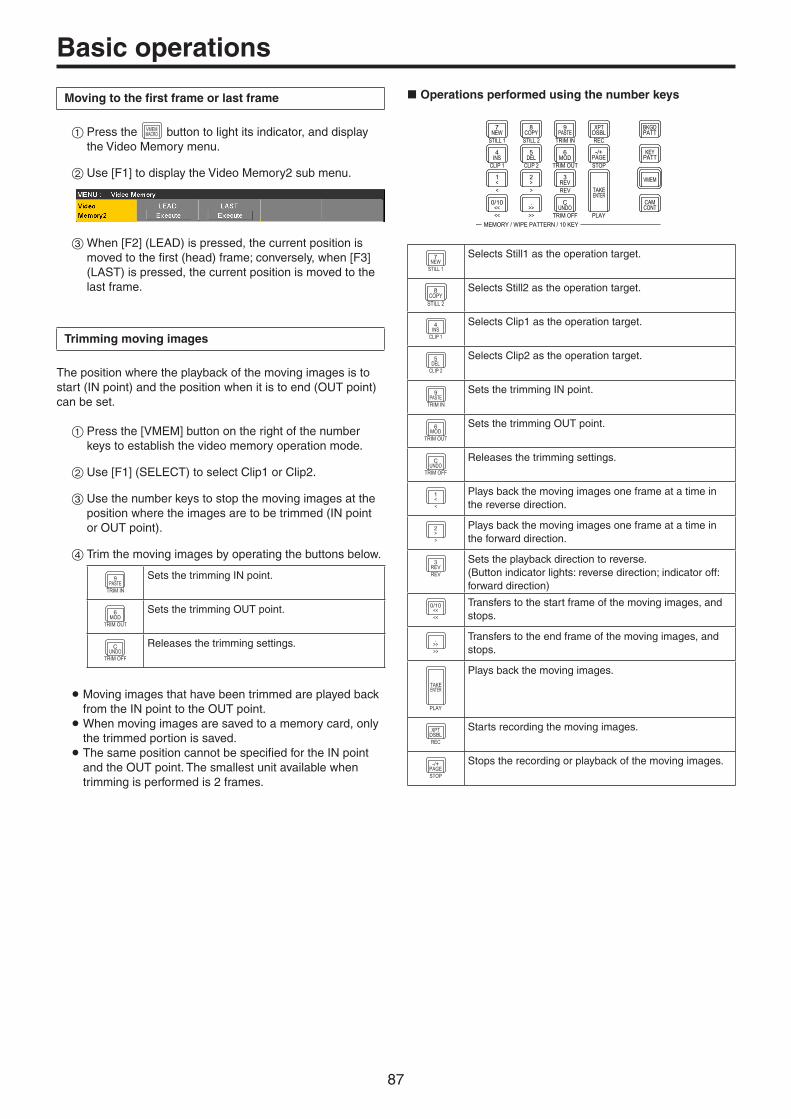
87
Basic operations
Moving to the first frame or last frame
1Press the VMEMMACRO button to light its indicator, and display
the Video Memory menu.
2Use [F1] to display the Video Memory2 sub menu.
3When [F2] (LEAD) is pressed, the current position is moved to the first (head) frame; conversely, when [F3] (LAST) is pressed, the current position is moved to the last frame.
Trimming moving images
The position where the playback of the moving images is to start (IN point) and the position when it is to end (OUT point) can be set.
1Press the [VMEM] button on the right of the number keys to establish the video memory operation mode.
2Use [F1] (SELECT) to select Clip1 or Clip2.
3Use the number keys to stop the moving images at the position where the images are to be trimmed (IN point or OUT point).
4Trim the moving images by operating the buttons below.
9PASTE
TRIM IN
Sets the trimming IN point.
6MOD
TRIM OUT
Sets the trimming OUT point.
CUNDO
TRIM OFF
Releases the trimming settings.
p Moving images that have been trimmed are played back from the IN point to the OUT point. pWhen moving images are saved to a memory card, only the trimmed portion is saved. p The same position cannot be specified for the IN point and the OUT point. The smallest unit available when trimming is performed is 2 frames.
w Operations performed using the number keys
VMEM
BKGDPATT
XPTDSBL
TAKEENTER
7NEW
8COPY
9PASTE
4INS
5DEL
6MOD
1<
2>
3REV
0/10<<
.>>
CUNDO
CAMCONT
KEYPATT
-/+PAGE
MEMORY / WIPE PATTERN / 10 KEY
STILL 1 STILL 2 TRIM IN REC
CLIP 1 CLIP 2 TRIM OUT
< > REV
<< >> TRIM OFF PLAY
STOP
7NEW
STILL 1
Selects Still1 as the operation target.
8COPY
STILL 2
Selects Still2 as the operation target.
4INS
CLIP 1
Selects Clip1 as the operation target.
5DEL
CLIP 2
Selects Clip2 as the operation target.
9PASTE
TRIM IN
Sets the trimming IN point.
6MOD
TRIM OUT
Sets the trimming OUT point.
CUNDO
TRIM OFF
Releases the trimming settings.
1<<
Plays back the moving images one frame at a time in the reverse direction.
2>>
Plays back the moving images one frame at a time in the forward direction.
3REVREV
Sets the playback direction to reverse.(Button indicator lights: reverse direction; indicator off: forward direction)
0/10<<<<
Transfers to the start frame of the moving images, and stops.
.>>>>
Transfers to the end frame of the moving images, and stops.
TAKEENTER
PLAY
Plays back the moving images.
XPTDSBLREC
Starts recording the moving images.
-/+PAGESTOP
Stops the recording or playback of the moving images.

88
Basic operations
Displaying thumbnails
pp When the [VMEM] button located on the right of the number keys is pressed and the video memory operation mode has been established, thumbnails of the images registered in the video memories (Still1, Still2, Clip1, Clip2) can be shown on the built-in display.
Thumbnail layout
w Still (still images)
Still image
Key signal indicatorThe “〇” icon is displayed when there is a key signal.
w Clip (moving images)
Image in the first frame of the clip
Key signal indicatorThe “〇” icon is displayed when there is a key signal.
Duration of the recorded clip
Duration of the range specified with trimming
Current playback position
Trimming IN point Trimming OUT point
Audio signal indicator
The “ ” icon is displayed when there is audio.

89
Basic operations
Memory card
The unit’s video memory data and setup data can be stored on memory card. Conversely, this data can be loaded from the memory card to the unit.Furthermore, it is possible to upgrade the unit’s software.pp It may take a while to store a moving image of a long
recording time with high image quality or a still image file with high image quality on the memory card.(Approximately 10 minutes is necessary when data with total size of about 490 MB stored in “All file” is saved to a Panasonic Class 8 SDHC memory card.)
Video memory (still image data: Still1, Still2):
<File formats supported>
Bitmap (bmp), JPEG (jpg), TARGA (tga), TIFF (tif), GIF (gif), PNG (png)
p This unit supports 24-bit uncompressed or 32-bit uncompressed TARGA files. If any other types of TARGA files are loaded into the unit, black images will be displayed as the thumbnails, and the unit cannot recognize the files.
p Be aware that saving video memory still images on the memory card in GIF format will cause the picture quality to deteriorate.
<Applicable sizes>
4K: 38402160HD/1080i: 19201080HD/1080PsF: 19201080HD/720p: 1280720
p The size of images is converted automatically if it does not match any of the “applicable sizes”.
Video memories (moving image data: Clip1, Clip2):This is the original format of the unit.Data is stored in and read from these memories.
Setup data (Set Up):The “setup data” refers to all the data stored in the unit with the exception of the following data.Project files can be saved.
Date, time, network settings, video memory data, shot memory data, event memory data, macro memory data
Software for upgrading (Upgrade):The software for upgrading is loaded. This software can be obtained from “Service and Support” on the Web site whose address is provided below:
https://pro-av.panasonic.net/
For the upgrade procedure, follow the steps in the directions which are contained in the download file.
Log file (Log):Log files stored in the unit can be saved.
pqConcerning memory cardsMemory cards used with the unit should conform to SD, SDHC or SDXC standards.Be sure to format cards using the unit.Use memory cards formatted with FAT. (NTFS formatted memory cards cannot be recognized.)Panasonic memory cards with the following capacities can be used with the unit:
SD (from 8 MB to 2 GB) SDHC (from 4 GB to 32 GB) SDXC (from 64 GB to 128 GB)
For the latest information not available in the Operating Instructions, visit the following Web sites.
https://pro-av.panasonic.net/
pp Memory cards must not be used or stored in an environment where they may be
• Exposed to high temperatures/humidities; • Exposed to water droplets; or • Electrically charged.

90
Basic operations
The data is stored in the following folders on the memory card.When data is to be loaded, first store the data in the respective folders, and then load the files.
<Data folder configuration>
Data type Save Type item Storage folder Extension
Project file (project) Project (*2) “HS\COMM\PROJECT” 001, 002, … (*3)
Video memory (Still file) Still1, Still2 (*1) “HS\COMM\IMAGE” bmp, tga, png, jpg (jpeg), tif (tiff), gif
Thumbnail image for video memory (Still file)
Still1, Still2 (*1) “HS\COMM\IMAGE_THUMBNAIL” tbm, tpn, tjp, ttg, ttif, tgi
Video memory (Clip file) Clip1, Clip2 (*1) “HS\COMM\CLIP” clp
Thumbnail image for video memory (Clip file)
Clip1, Clip2 (*1) “HS\COMM\CLIP_THUMBNAIL” png
Update file – “HS\UHS500\UPDATE” 50d
Log file Log “HS\UHS500\LOG” log
*1: When the still image data with key signals attached is stored into the video memory, select “tga” or “png” as the file format. The still image data of any other file format cannot be stored with attaching the key signals. In 4K mode, only Still1 and Clip1 are available.
*2: The project file is a collection of data selected in the Target Select item; setup data, shot memory data, event memory data, macro memory data, still image data, and moving image data.
*3: The project file is saved in a folder created as File Name folder created under the HS\COMM\PROJECT folder. When the project file being stored is large, the file is divided and each file is appended with a serial number extension (001, 002, etc.).
Memory card handling precautionsp Do NOT eject the memory card while the memory card access LED is lit. When an memory card is ejected while the memory card access LED is lit, the transition may be temporarily suspended.
In addition, the data stored on the memory card may be lost.p The data stored on memory cards may be lost as a result of misplacing the cards or performing erroneous operations, for
instance. It is recommended that valuable data be stored on a computer or other device.
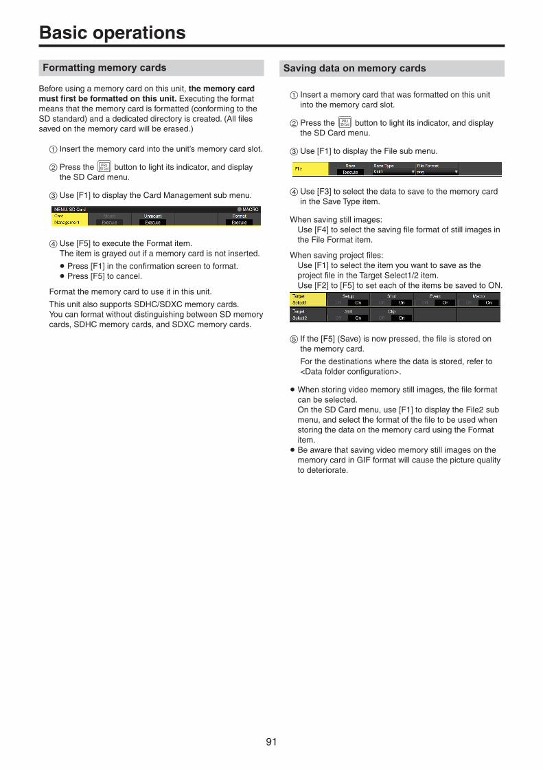
91
Basic operations
Formatting memory cards
Before using a memory card on this unit, the memory card must first be formatted on this unit. Executing the format means that the memory card is formatted (conforming to the SD standard) and a dedicated directory is created. (All files saved on the memory card will be erased.)
1Insert the memory card into the unit’s memory card slot.
2Press the PRJSD Card button to light its indicator, and display
the SD Card menu.
3Use [F1] to display the Card Management sub menu.
4Use [F5] to execute the Format item. The item is grayed out if a memory card is not inserted.
p Press [F1] in the confirmation screen to format. p Press [F5] to cancel.
Format the memory card to use it in this unit.
This unit also supports SDHC/SDXC memory cards.You can format without distinguishing between SD memory cards, SDHC memory cards, and SDXC memory cards.
Saving data on memory cards
1Insert a memory card that was formatted on this unit into the memory card slot.
2Press the PRJSD Card button to light its indicator, and display
the SD Card menu.
3Use [F1] to display the File sub menu.
4Use [F3] to select the data to save to the memory card in the Save Type item.
When saving still images:Use [F4] to select the saving file format of still images in the File Format item.
When saving project files:Use [F1] to select the item you want to save as the project file in the Target Select1/2 item.Use [F2] to [F5] to set each of the items be saved to ON.
5If the [F5] (Save) is now pressed, the file is stored on the memory card.
For the destinations where the data is stored, refer to <Data folder configuration>.
pWhen storing video memory still images, the file format can be selected. On the SD Card menu, use [F1] to display the File2 sub menu, and select the format of the file to be used when storing the data on the memory card using the Format item. p Be aware that saving video memory still images on the memory card in GIF format will cause the picture quality to deteriorate.

92
Basic operations
Loading data from memory cards
1Insert the memory card on which the data is stored into the memory card slot. Load the file after its data has been stored in the each folder. Data stored in other folders will not be recognized by the unit.
For the destinations where the data is stored, refer to <Data folder configuration>.
2On the SD Card menu, use [F1] to display the Mode sub menu.
3Use [F2], and then press the [F2] using the Load item. When [F2] is pressed, the file selection screen is displayed.
<Example of what appears on the file selection screen>
4Use [F1] to select the type of file to be loaded using the SELECT item.
p Correlation between [F1] (for selecting a setting using the SELECT item) and [F3] on the file selection screen
[F1]Settings selected
using SELECT item
[F3]Displays and function
Still1, Still2,Clip1, Clip2
F3: LIST VIEWUsing the [F3], it is possible to switch the screen display between “List (list files)” and “Thumbnail (display thumbnails)”.pp Only Still1 and Clip1 can be selected in the 4K mode.
Upgrade F3: The [F3] cannot be operated.On the screen, the list of files is displayed.
Project F3: The [F3] cannot be operated.On the screen, the list of files is displayed.
5Use [F2] to select the name of the file to be loaded using the SELECT FILE item. If the name of the file to be loaded consists of more than 23 characters, a shortened version of the filename will be displayed.
p The following alphanumerics and symbols can be used as the characters for filenames (see below). Files using other characters will not be displayed by the unit. p Periods are not available in the input screen. Characters that are not available in the keyboard screen are grayed out.
<Characters which can be used for filenames>
A to Z, a to z, 0 to 9, ! # $ % & ' ( ) @ ^ _ ` { }
6Use [F4] to load the file.
Thumbnail display
For Still thumbnails, the image is displayed in the upper portion, and the file name, KEY indicator, image size, and file date are displayed in the lower portion.For Clip thumbnails, a still image is displayed in the upper portion, and the file name, KEY indicator, recorded time (number of frames), format, and file date are displayed in the lower portion.A maximum of up to 100 Still thumbnails and 100 Clip thumbnails can be displayed.On a single screen, 8 thumbnails are displayed in 2 rows of 4 thumbnails each. For more than 8 thumbnails, thumbnails are switched one row at a time.When moving the cursor with [F2] (the SELECT item), if the cursor is at the image in the lower-right corner (or upper-left corner), moving to the right (or left) switches pages.pp Never remove the memory card while thumbnail display is
in progress.

93
Basic operations
Changing the sort mode
The way in which the file list displayed on the file selection screen is arranged can be specified.
1On the SD Card menu, use [F1] to display the Mode sub menu.
2Use [F5] to select the sort mode for the file selection screen using the Sort item.
Newest The files are arranged in sequence starting with the file having the most recent registration date and time.
Oldest The files are arranged in sequence starting with the file having the oldest registration date and time.
Name The files are arranged in filename sequence.
Deleting files on memory cards
1Insert the memory card on which the data is stored into the memory card slot.
2On the SD Card menu, use [F1] to display the Mode sub menu.
3Use [F3] to select “Delete” using the Mode item, and then press the [F3]. When [F3] is pressed, the file selection screen is displayed.
<Example of what appears on the file selection screen>
4Use [F1] to select the type of file to be deleted using the SELECT item. If the name of the file to be loaded consists of more than 23 characters, a shortened version of the filename will be displayed.
5Use [F2] to select the name of the file to be deleted using the SELECT FILE item.
6Use [F4] to delete the file.

94
Basic operations
Displaying the memory card information
1Insert the memory card on which the data is stored into the memory card slot.
2On the SD Card menu, use [F1] to display the Card Information sub menu.
Free The memory card’s remaining free space is displayed.
Total The memory card’s capacity is displayed.
Creating thumbnail images
1Insert the memory card on which the data is stored into the memory card slot.
2On the SD Card menu, use [F1] to display the Create Thumbnail sub menu.
3Use [F2] to create the thumbnail for still images in the Still item.
4Use [F3] to create the thumbnail for moving images in the Clip item.

95
Basic operations
Waveform monitor settings
WFM (waveform monitor) settings
1Press the [WFM/VECT] button among the display mode buttons to display the waveform monitor on the built-in display.
2Press the CONFSYS button to light its indicator, and display
the Config menu.
3Use [F1] to display the WFM sub menu.
4Use [F2] to select the method to be used to display the signal waveforms using the Style item.
Parade The signal waveforms are arranged and displayed.
Overlay The signal waveforms are superimposed onto each other and displayed.
5Use [F3] to select the signals whose waveforms are to be displayed using the Mode item.
YPbPr Waveforms of the Y, PB and PR signals are displayed.
RGB Waveforms of the R, G and B signals are displayed.
Y Waveforms of the Y signal only are displayed.
VECTOR (vectorscope) settings
1Press the [WFM/VECT] button among the display mode buttons to display the vectorscope on the built-in display.
2Press the CONFSYS button to light its indicator, and display
the Config menu.
3Use [F1] to display the Vector sub menu.
4Use [F2] to select the color bar reference marker using the Bar Target item.
75% The 75% color bar reference marker is displayed.
100% The 100% color bar reference marker is displayed.

96
Input/output signal settings
Input signal settings
IN1 and IN2 are exclusive input by SDI signals or HDMI signals.SDI IN3 to 8 are SDI signal inputs.IN-A1 to 4, IN-B1 to 4 can be set only when one of the following optional units has been connected.
AV-UHS5M1 (SDI Input Unit) IN-A1 to A4 and IN-B1 to B4 can be set.
AV-UHS5M3 (HDMI Input Unit) IN-A1 to A3 and IN-B1 to B3 can be set.
Before setting the input signals, first select the input signal to be set using the Input sub menu.
1Press the INOUT button to light its indicator, and display the Input menu.
2Use [F1] to display the Input sub menu.
3Use [F2] to select the input signals using the Select item.
The menu display is switched in accordance with the input signals which have been selected.The menu title is set to “MENU: Input (signal type)/input connector (material name)”.
Signal type SDI, HDMI
Material name Material name set in “Setting the material names”.
<Example of menu (SDI)>

97
Input/output signal settings
<List of settings by input signal>
Input connector
Setting menu and page in this manual
Color Space Status FS Freeze Limited Name
P 98 P 99 P 99 P 100 P 100 P 101
12G SDI IN1, 12G SDI IN2HDMI IN1, HDMI IN2
Exclusionary input
StandardSDI input 2 lines
-
StandardHDMI input 2 lines
- -
12G SDI IN3, 12G SDI IN4
StandardSDI input 2 lines
-
12G SDI IN5 to 12G SDI IN8
StandardSDI input 4 lines
-
Option slotIN-A1 to IN-A4IN-B1 to IN-B4
AV-UHS5M1
SDI input 4 lines -
Option slotIN-A1 to IN-A3IN-B1 to IN-B3
AV-UHS5M3
HDMI input 3 lines - -
Input connector
Setting menu and page in this manual
Up/Down Converter
C/C HDMI Status HDMI Input ScaleCamera Settings
P 101 P 102 P 106 P 105 P 110 P 130
12G SDI IN1, 12G SDI IN2HDMI IN1, HDMI IN2
Exclusionary input
StandardSDI input 2 lines
- - - - -
StandardHDMI input 2 lines
- -
12G SDI IN3, 12G SDI IN4
StandardSDI input 2 lines
- - - - -
12G SDI IN5 to 12G SDI IN8
StandardSDI input 4 lines
- - -
Option slotIN-A1 to IN-A4IN-B1 to IN-B4
AV-UHS5M1
SDI input 4 lines - - -
Option slotIN-A1 to IN-A3IN-B1 to IN-B3
AV-UHS5M3
HDMI input 3 lines-
: Can be set. —: Cannot be set.

98
Input/output signal settings
Settings for the exclusionary input connectors
Set the exclusionary input for the SDI input connectors (12G SDI IN1, 12G SDI IN2)/HDMI input connectors (HDMI IN1, HDMI IN2).These settings are for IN1 and IN2 which can be selected in the Select item of the Input sub menu.
1Press the INOUT button to light its indicator, and display
the Input menu.
2Use [F1] to display the Input sub menu.
3Use [F2] to select the input signals using the Select item.
4Use [F5] to set the input signal type in the SDI/HDMI item.
SDI IN Selects the SDI signal input to 12G SDI IN1/2 for IN1/2. Even if HDMI signals are input, they are not input to this unit.
HDMI IN Selects the HDMI signal input to HDMI IN1/2 for IN1/2. Even if SDI signals are input, they are not input to this unit.
Settings for the color range for input signals
Set the color range for input signals.You can set all input signals independently.
1Press the INOUT button to light its indicator, and display
the Input menu.
2Use [F1] to display the Input sub menu.
3Use [F2] to select the input signals using the Select item.
4Use [F4] to set the color range in the Color Space item.
HDR BT.2020 High dynamic range, color range entered is Rec.2020.
HDR BT.709 High dynamic range, color range entered is Rec.709.
SDR BT.709 Standard dynamic range, color range entered is Rec.709.

99
Input/output signal settings
Checking the input signal status
You can check the status of input signals.
For SDI input signals
1Use [F1] to display the Status sub menu.
The unit automatically determines the content of input signals and displays the following information.
Format Displays the image format information for the SDI signal being input.
Audio Displays the audio information for the SDI signal being input.
Color Space Displays the color space information for the SDI signal being input.
For HDMI input signals
1Use [F1] to display the HDMI Status sub menu.
The unit automatically determines the content of input signals and displays the following information.
Size Displays the resolution information for the HDMI signal being input.
Dot Clock Displays the dot clock information for the HDMI signal being input.
H-Frequency Displays the horizontal frequency information for the HDMI signal being input.
V-Frequency Displays the vertical frequency information for the HDMI signal being input.
Setting the frame synchronizer
The frame synchronizer can be set to On or Off for each input.The HDMI input frame synchronizer is permanently On. It cannot be set from On to Off or vice versa.
1On the Input sub menu, use [F2] to select the input to be set using the Select item. Refer to “Input signal settings”.
2Use [F1] to display the FS sub menu.
3Use [F3] to set the frame synchronizer in the FS item.
Off Turns the frame synchronizer Off. The line synchronizer function operates in this case.The line synchronizer function automatically adjusts the phases of input video signals to match the phases of the horizontal sync signals.
Normal Enables the frame synchronizer function. When a signal that is different from the system format is input, the screen turns black.
Auto Enables the frame synchronizer function. Even when a signal that is different from the system format is input, the screen does not turn black.The video output in this case may be disrupted.
p If the output signal phase is set to [0H], Off cannot be selected as the FS item setting. If the FS item is set to Off, this changes to Normal. pWhen inputting 3G-SDI Level B Mapping signals, set the frame synchronizer setting to [Auto].

100
Input/output signal settings
Setting the delay amount
The input signals can be delayed.pp This setting is for input signals to 12G SDI IN5 to 8 and the
optional SDI input unit (IN-A1 to 4 and IN-B1 to 4).
1On the Input sub menu, use [F2] to select the input to be set using the Select item. Refer to “Input signal settings”.
2Use [F1] to display the FS sub menu.
3Use [F3] to set the delay amount using the Delay item.
Freezing the input signals
The input signals can be frozen and used. While signals are frozen, the tally signals of the corresponding input will not be output.
Setting freeze
1On the Input sub menu, use [F2] to select the input to be set using the Select item. Refer to “Input signal settings”.
2Use [F1] to display the Freeze sub menu.
Frame The images are frozen frame by frame.
Field The images are frozen field by field.This is used to freeze moving images.With interlace signals, however, diagonal lines and moving parts appear jagged.
Frame or Field can also be selected while an image is frozen.
3Press the [F3] to freeze the input image or cancel the freeze.
If the [F3] is pressed while the display is “Off”, the video signal is frozen, and the display is set to “On”.
If the [F3] is pressed while the display is “On”, the video signal freezing is canceled, and the display is set to “Off”.
The “F” mark appears in front of the name of the material when the signals set for output of multi view displays are frozen.
pWhen the unit is used with the frame synchronizer function OFF, the output images may be disturbed when freezing is executed, but the frozen images will not be adversely affected. p If, when the switcher is used with the frame synchronizer function at OFF, “On” is set as the freeze setting, the frame synchronizer function will be automatically switched to ON.

101
Input/output signal settings
Setting the material names
Material names can be given to the input signals.These names can be selected from the default settings or user settings.
1On the Input sub menu, use [F2] to select the input to be set using the Select item. Refer to “Input signal settings”.
2Use [F1] to display the Name sub menu.
3Use [F2] to select the type of material names using the Type item.
Default(default settings)
Select the material names from the following: IN1, IN2, 12G SDI IN3 to 8, IN-A1 to 4, IN-B1 to 4
User(user settings)
The material names are set using up to 32 characters.
Setting the up-converter
Select the settings for SDI IN5 to SDI IN8, as well as for the up-converter that is built into the optional unit listed below:
p AV-UHS5M1 (SDI Input Unit)
1On the Input sub menu, use [F2] to select the input to be set using the Select item. Refer to “Input signal settings”.
2Use [F1] to display the Up/Down Converter sub menu.
3Use [F2] to set the image movement detection sensitivity using the Move Detect item.
1 Toward still images
3 Standard
5 Toward moving images
4Use [F3] to set the extent of the edge sharpness for the images using the Sharp item.
1 Not sharp edges
3 Standard
5 Very sharp edges

102
Input/output signal settings
Color Corrector
Make settings for the Color Correctors built in to SDI IN5 to SDI IN8 and the following optional units.
1On the Input sub menu, use [F2] to select the input to be set using the Select item. Refer to “Input signal settings”.
Color Corrector settings
1Use [F1] to display the C/C Operation sub menu.
2Use [F2] to set the Color Corrector to enable (On)/disable (Off).
3Use [F3] to set the color range of the input signal in the Limit item.
Off No limit on color range.
108 The amplitude level of each color (R, G, B) is limited to between 0% and 108%.
104 The amplitude level of each color (R, G, B) is limited to between 0% and 104%.
100 The amplitude level of each color (R, G, B) is limited to between 0% and 100%.
Process control
1Use [F1] to display the C/C Process sub menu.
2Use [F2] to set the gain value of the Y signal in the Y-Gain item.
3Use [F3] to set the value of the pedestal level in the Pedestal item.
4Use [F4] to set the gain value of the saturation in the C-Gain item.
5Use [F5] to set the amount of change of the color hue in the Hue item.
Tone curve
Corrects the tone of the input signal.Set the tone curve to adjust the brightness, contrast, etc., of images.You can adjust the white balance and the color tone by separately adjusting each of the R, G, and B colors.
Tone1 Black Tone2 Gray L Tone3 Gray H Tone4 White
Tone1 Black Adjusts the black level.
Tone2 Gray L Adjusts the gray Low level.
Tone3 Gray H Adjusts the gray High level.
Tone4 White Adjusts the white level.
1Use [F1] to display the C/C Tone1 Black sub menu.
2Use [F2] to adjust the R signal of the black level in the Red item.
3Use [F3] to adjust the G signal of the black level in the Green item.
4Use [F4] to adjust the B signal of the black level in the Blue item.
5Use [F5] to make the link settings for the adjustment value in the RGB Link item.
Off RGB can be independently set in each of the C/C Tone1 Black, C/C Tone2 Gray L, C/C Tone3 Gray H, and C/C Tone4 White sub menus.
On The Red setting value is set in Green and Blue in each of the C/C Tone1 Black, C/C Tone2 Gray L, C/C Tone3 Gray H, and C/C Tone4 White sub menus.
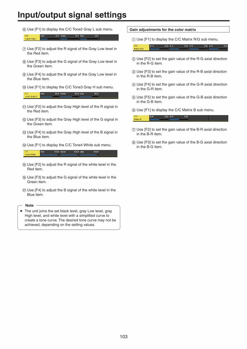
103
Input/output signal settings
6Use [F1] to display the C/C Tone2 Gray L sub menu.
7Use [F2] to adjust the R signal of the Gray Low level in the Red item.
8Use [F3] to adjust the G signal of the Gray Low level in the Green item.
9Use [F4] to adjust the B signal of the Gray Low level in the Blue item.
Use [F1] to display the C/C Tone3 Gray H sub menu.
Use [F2] to adjust the Gray High level of the R signal in the Red item.
Use [F3] to adjust the Gray High level of the G signal in the Green item.
Use [F4] to adjust the Gray High level of the B signal in the Blue item.
> Use [F1] to display the C/C Tone4 White sub menu.
Use [F2] to adjust the R signal of the white level in the Red item.
Use [F3] to adjust the G signal of the white level in the Green item.
Use [F4] to adjust the B signal of the white level in the Blue item.
pp The unit joins the set black level, gray Low level, gray High level, and white level with a simplified curve to create a tone curve. The desired tone curve may not be achieved, depending on the setting values.
Note
Gain adjustments for the color matrix
1Use [F1] to display the C/C Matrix R/G sub menu.
2Use [F2] to set the gain value of the R-G axial direction in the R-G item.
3Use [F3] to set the gain value of the R-B axial direction in the R-B item.
4Use [F4] to set the gain value of the G-R axial direction in the G-R item.
5Use [F5] to set the gain value of the G-B axial direction in the G-B item.
6Use [F1] to display the C/C Matrix B sub menu.
7Use [F2] to set the gain value of the B-R axial direction in the B-R item.
8Use [F3] to set the gain value of the B-G axial direction in the B-G item.

104
Input/output signal settings
Initializing the color corrector
1Use [F1] to display the C/C Setting sub menu.
2Use [F2] to select the initialization target in the Init Target item.
Process The settings in the C/C Process sub menu are initialized.
Tone The settings in the C/C Tone1 Black, C/C Tone2 Gray L, C/C Tone3 Gray H, and C/C Tone4 White sub menu are initialized.
RGB Matrix The settings in the C/C Matrix R/G and C/C Matrix B sub menu are initialized.
All All are initialized.
Copying settings
You can copy the Color Corrector setting information that was set for another input.
1Use [F1] to display the C/C Setting sub menu.
2Use [F4] to select the copy target in the Copy Target item.
3When the Copy From item in [F5] is pressed, the settings selected as the Copy Target are copied.

105
Input/output signal settings
Setting the HDMI input signals
Set the HDMI input signals when the HDMI input unit (optional) or full-HD HDMI input unit (optional) has been connected.Signals with the following resolutions can be input.
HDMI input signalsStandard(Digital)
HDMI Input Unit(Digital)
AV-UHS5M3
XGA(1024×768)/60 Hz
WXGA(1280×768)/60 Hz
SXGA(1280×1024)/60 Hz
WSXGA+(1680×1050)/60 Hz
UXGA(1600×1200)/60 Hz
WUXGA(1920×1200)/60 Hz
WQHD(2560×1440)/60 Hz
720/59.94p(1280×720)/59.94 Hz
720/50p(1280×720)/50 Hz
1080/59.94i(1920×1080)/59.94 Hz
1080/50i(1920×1080)/50 Hz
1080/23.98p (1920×1080)/23.98 Hz
1080/24p(1920×1080)/24 Hz
1080/25p(1920×1080)/25 Hz
1080/29.97p(1920×1080)/29.97 Hz
1080/59.94p(1920×1080)/59.94 Hz
1080/50p(1920×1080)/50 Hz
2160/23.98p(3840×2160)/23.98 Hz
2160/24p(3840×2160)/24 Hz
2160/25p(3840×2160)/25 Hz
2160/29.97p(3840×2160)/29.97 Hz
2160/59.94p(3840×2160)/59.94 Hz
2160/50p(3840×2160)/50 Hz
: Can be set.—: Cannot be set.
pp If signals with any other resolutions or frequencies are input, the signals cannot be imported correctly. The images which are output at a time like this may be black or disturbed.pp These units are incompatible with the HDCP (High-
bandwidth Digital Content Protection).
1On the Input sub menu, use [F2] to select the input to be set using the Select item. Refer to “Input signal settings”.
2Use [F1] to display the HDMI Input sub menu.
3Use [F2] to select the scaling method.
Fit-V The aspect ratio of the input images is maintained, and the size of the images is increased or reduced in accordance with the vertical resolution.
Fit-H The aspect ratio of the input images is maintained, and the size of the images is increased or reduced in accordance with the horizontal resolution.
Full The size of the input images is increased or reduced in accordance with the system resolution.(The aspect ratio of the input images is not kept the same. The rate at which the image size is increased or reduced in the vertical direction and in the horizontal direction differs.)

106
Input/output signal settings
Displaying the HDMI input signal information
These are used to display the information concerning the HDMI input signal images. The information cannot be changed.
1On the Input sub menu, use [F2] to select the input to be set using the Select item. Refer to “Input signal settings”.
2Use [F1] to display the HDMI Status sub menu.
Size This indicates the pixel count of the images.
Dot Clock This indicates the dot clock frequency of the images.
H-Frequency This indicates the horizontal frequency of the images.
V-Frequency This indicates the vertical frequency of the images.
The formats supported are listed below.
<HDMI formats supported>
HDMI input signalDot clock frequency
(MHz)
Frequency
Horizontal (kHz)
Vertical (Hz)
XGA 1024×768 Digital 65.0 48.36 60.00
WXGA 1280×768 Digital 79.5 47.78 59.87
SXGA 1280×1024 Digital 108.0 63.98 60.02
WSXGA+ 1680×1050 Digital 146.2 65.29 59.95
UXGA 1600×1200 Digital 162.0 75.00 60.00
WUXGA 1920×1200 Digital 154.0 74.04 59.95
WQHD 2560×1440 Digital 241.5 88.79 59.95
720/59.94p 1280×720 Digital 74.25/1.001 44.96 60.00/1.001
720/50p 1280×720 Digital 74.25 37.50 50.00
1080/59.94i 1920×1080 Digital 74.25/1.001 33.72 60.00/1.001
1080/50i 1920×1080 Digital 74.25 28.13 50.00
1080/23.98p 1920×1080 Digital 74.2 27.0 24.00/1.001
1080/24p 1920×1080 Digital 74.2 27.0 24.00
1080/25p 1920×1080 Digital 74.2 28.1 25.00
1080/29.97p 1920×1080 Digital 74.2 33.7 30.00
1080/59.94p 1920×1080 Digital 148.5/1.001 67.50/1.001 60.00/1.001
1080/50p 1920×1080 Digital 148.5 56.25 50.00
2160/23.98p 3840×2160 Digital 297.0/1.001 53.9 24.00/1.001
2160/24p 3840×2160 Digital 297.0 54.0 24.00
2160/25p 3840×2160 Digital 297.0 56.2 25.00
2160/29.97p 3840×2160 Digital 297.0/1.001 67.40 30.00
2160/59.94p 3840×2160 Digital 594.0/1.001 134.9 60.00/1.001
2160/50p 3840×2160 Digital 594.0 112.5 50.00
pp If the format of the input signals is not supported, it may not be possible to import the signals properly, and a black image or disturbed image may appear.
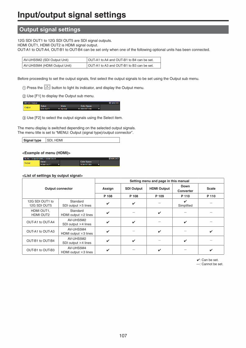
107
Input/output signal settings
Output signal settings
12G SDI OUT1 to 12G SDI OUT5 are SDI signal outputs.HDMI OUT1, HDMI OUT2 is HDMI signal output.OUT-A1 to OUT-A4, OUT-B1 to OUT-B4 can be set only when one of the following optional units has been connected.
AV-UHS5M2 (SDI Output Unit) OUT-A1 to A4 and OUT-B1 to B4 can be set.
AV-UHS5M4 (HDMI Output Unit) OUT-A1 to A3 and OUT-B1 to B3 can be set.
Before proceeding to set the output signals, first select the output signals to be set using the Output sub menu.
1Press the INOUT button to light its indicator, and display the Output menu.
2Use [F1] to display the Output sub menu.
3Use [F2] to select the output signals using the Select item.
The menu display is switched depending on the selected output signals. The menu title is set to “MENU: Output (signal type)/output connector”.
Signal type SDI, HDMI
<Example of menu (HDMI)>
<List of settings by output signal>
Output connector
Setting menu and page in this manual
Assign SDI Output HDMI OutputDown
ConverterScale
P 108 P 108 P 109 P 110 P 110
12G SDI OUT1 to 12G SDI OUT5
StandardSDI output 5 lines
- Simplified
-
HDMI OUT1, HDMI OUT2
StandardHDMI output 2 lines
- - -
OUT-A1 to OUT-A4AV-UHS5M2
SDI output 4 lines - -
OUT-A1 to OUT-A3AV-UHS5M4
HDMI output 3 lines - -
OUT-B1 to OUT-B4AV-UHS5M2
SDI output 4 lines - -
OUT-B1 to OUT-B3AV-UHS5M4
HDMI output 3 lines - -
: Can be set. —: Cannot be set.

108
Input/output signal settings
Assigning the output signals
The output signals can be assigned to the 12G SDI OUT connector and HDMI OUT connector.
1On the Output sub menu, use [F2] to select the output to be set using the Select item. Refer to “Output signal settings”.
2Use [F1] to display the Assign sub menu.
3Use [F2] to set the type of output signal using the Source item.
PGM An image provided with the wipe, mix, key, downstream key or other effect is output at the switcher’s main line output.
PVW This is the preview output that enables the next operation to be checked before it is executed.
CLN The clean signal (the image resulting when the key, downstream key or other effect has been removed from the PGM signal) is output.
ME PGM ME PGM signals (images without the downstream key effects) are output.
AUX1 to 4 The signals selected by the 4 lines of AUX buses (AUX1 to AUX4) are output.
MV1, MV2 The multi view display signals are output. Multiple input signals and output signals are reduced in size and output to one screen.
KeyOut The key signal is output.
4Use [F3] to set the output mode using the Mode item.
Normal The same signals as the system format signals are output.
Simplified down-converter
When the system format is 2160/59.94p, the signals are output in the 1080/59.94p format.
Down-converter
This can be selected when the SDI output unit (optional: AV-UHS5M1) has been connected.When the system format is 2160/59.94p, the signals are output in the 1080/59.94p, 1080/59.94i or 720/59.94p format.When the system format is 1080/59.94p, the signals are output in the 1080/59.94i or 720/59.94p format.When the system format is 1080/59.94i, the signals are output in the 720/59.94p format.
Setting the SDI output color range
The color range can be set for the SDI output signal images.pp You can set all output signals independently.
1On the Output sub menu, use [F4] to set Color Space.
HDR BT.2020 High dynamic range, color range output is Rec.2020.
HDR BT.709 High dynamic range, color range output is Rec.709.
SDR BT.709 Standard dynamic range, color range output is Rec.709.
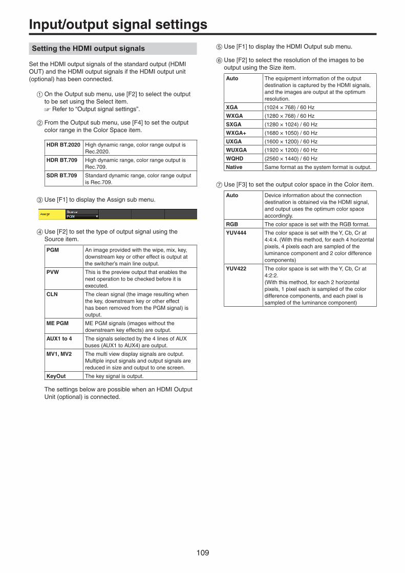
109
Input/output signal settings
Setting the HDMI output signals
Set the HDMI output signals of the standard output (HDMI OUT) and the HDMI output signals if the HDMI output unit (optional) has been connected.
1On the Output sub menu, use [F2] to select the output to be set using the Select item. Refer to “Output signal settings”.
2From the Output sub menu, use [F4] to set the output color range in the Color Space item.
HDR BT.2020 High dynamic range, color range output is Rec.2020.
HDR BT.709 High dynamic range, color range output is Rec.709.
SDR BT.709 Standard dynamic range, color range output is Rec.709.
3Use [F1] to display the Assign sub menu.
4Use [F2] to set the type of output signal using the Source item.
PGM An image provided with the wipe, mix, key, downstream key or other effect is output at the switcher’s main line output.
PVW This is the preview output that enables the next operation to be checked before it is executed.
CLN The clean signal (the image resulting when the key, downstream key or other effect has been removed from the PGM signal) is output.
ME PGM ME PGM signals (images without the downstream key effects) are output.
AUX1 to 4 The signals selected by the 4 lines of AUX buses (AUX1 to AUX4) are output.
MV1, MV2 The multi view display signals are output. Multiple input signals and output signals are reduced in size and output to one screen.
KeyOut The key signal is output.
The settings below are possible when an HDMI Output Unit (optional) is connected.
5Use [F1] to display the HDMI Output sub menu.
6Use [F2] to select the resolution of the images to be output using the Size item.
Auto The equipment information of the output destination is captured by the HDMI signals, and the images are output at the optimum resolution.
XGA (1024 × 768) / 60 Hz
WXGA (1280 × 768) / 60 Hz
SXGA (1280 × 1024) / 60 Hz
WXGA+ (1680 × 1050) / 60 Hz
UXGA (1600 × 1200) / 60 Hz
WUXGA (1920 × 1200) / 60 Hz
WQHD (2560 × 1440) / 60 Hz
Native Same format as the system format is output.
7Use [F3] to set the output color space in the Color item.
Auto Device information about the connection destination is obtained via the HDMI signal, and output uses the optimum color space accordingly.
RGB The color space is set with the RGB format.
YUV444 The color space is set with the Y, Cb, Cr at 4:4:4. (With this method, for each 4 horizontal pixels, 4 pixels each are sampled of the luminance component and 2 color difference components)
YUV422 The color space is set with the Y, Cb, Cr at 4:2:2. (With this method, for each 2 horizontal pixels, 1 pixel each is sampled of the color difference components, and each pixel is sampled of the luminance component)

110
Input/output signal settings
8Use [F4] to select the scaling method using the Scale item.
Fit-V The aspect ratio of the output images is maintained, and the size of the images is increased or reduced in accordance with the vertical resolution. (Black bands are inserted into the areas where there are no images. The protruding parts of the images are cropped.)
Fit-H The aspect ratio of the output images is maintained, and the size of the images is increased or reduced in accordance with the horizontal resolution.(Black bands are inserted into the areas where there are no images. The protruding parts of the images are cropped.)
Full The size of the output images is increased or reduced in accordance with the system resolution.
Fullx80% The size of the output image is increased or reduced in accordance with the 80% size of the system resolution.
Fullx90% The size of the output image is increased or reduced in accordance with the 90% size of the system resolution.
p The aspect ratio is not maintained at the Full, Fullx80% or Fullx90% setting. The rate at which the image size is increased or reduced in the vertical direction and in the horizontal direction differs.
9Use [F5] to set the image movement detection sensitivity using the Move Detect item.
1 Toward still images
3 Standard
5 Toward moving images
Setting the down-converter (optional)
Select the settings for the down-converter that is built into the SDI output unit (AV-UHS5M2).
1On the Output sub menu, use [F2] to select the output to be set using the Select item. Refer to “Output signal settings”.
2Use [F1] to display the Down Converter sub menu.
3Use [F2] to set the delay time of the output using the Delay item.
Minimum Output is with the minimum delay of the system. Refer to "Adjusting the output signal phase" for the size of phase delays.
1F Fix The image is output in-phase with a delay of1 frame from the system image (HD).
4Use [F3] to set the extent of the edge sharpness for the images using the Sharp item.
1 Standard
5 Very sharp edges

111
Input/output signal settings
Setting the sync signals
The sync signals to be used by the system can be selected.External sync: For synchronization with an external sync signal
(gen-lock). The reference input signal is looped through and output.
BB Black burst signal (vertical phase of 0H)
BB Advanced
Black burst signalVertical phase of 90H when the 59.94i or 59.94p format is selected; vertical phase of 75H when the 50i or 50p format is selected
Tri-level sync Tri-level sync signal (vertical phase of 0H)
Internal For synchronization with an internal reference signal (INT). The REFOUT signal (black burst signal) is output from the two reference connectors.p This cannot be selected when the system
format is 1080/24PsF.
pWhen the format is 1080/24PsF, only Tri-level sync can be selected.
p This unit supports synchronization signals for field frequencies that are same as those of the system format. When the unit is set to the 1080/23.98PsF format, however, the unit also supports black burst signals with 10F-1D (compliant with the SMPTE318M standard).
1Press the CONFSYS button to light its indicator, and display
the System menu.
2Use [F1] to display the Reference sub menu.
3Use [F2], select the sync signal using the Sync item, and press the [F2] to enter the selection.
4Use [F3] to select the setup level of the black burst signal in the internal synchronization mode using the BB Setup item. This setting takes effect when the video system is 59.94i or 59.94p. The setup level is fixed at 0 IRE when the system is 50i or 50p.
5The genlock status is displayed in the Gen Lock item.
Locked Synchronized with the external sync signal or internal reference signal.
UnLock Not synchronized with the external sync signal or internal reference signal.
Adjusting the output signal phase
The phase of the output video signals can be adjusted.
1Press the CONFSYS button to light its indicator, and display
the System menu.
2Use [F1] to display the Output Phase sub menu.
3Use [F2], and select “0H” or “1H” using the System item.
0H The output video signals are output to the system Reference signal with using in-phase. The frame synchronizer function is ON for all input signals.
1H The output video signals are output to the system Reference signal with 1H delay. When the frame synchronizer function is ON, the output video signals are output with 1 frame + 1H delay.
4Use [F3] to adjust H phase using the H-Phase item. H-Phase can be adjusted within a range of –0.50H to +0.49H.
p The setting displayed on the menu differs depending on the system format.
5Use [F4] to adjust V phase using the V-Phase item. V-Phase can be adjusted within a range of –100H to +100H.

112
Input/output signal settings
<Phase adjustment setup>
Reference (Phase Reference)
H Phase (–0.5H to +0.5H) + V Phase (±100 lines)
InternalFixed DL
Approx. 0.2H
• 0H Output (1F delay for Reference and in-phase output)
FS Range
MAX less than approximately 1 frame
Longest Output(+1.5H)
Approx. 0.3H
+0.5H
Output Phase Variable Range
Output Phase Variable Range
H Phase (–0.5H to +0.5H) + V Phase (±100 lines)
Approx. +0.3H to +1.3H InternalFixed DL
Line Synchronizer Range
Reference(System standard)
• 1H Output (+1H)
ShortestOutput (+0.5H)
Output Phase Variable Range
H Phase (–0.5H to +0.5H) + V Phase (±100 lines)
Approx. 0.3H
+0.5H
InternalFixed DL
Approx. –0.7H to +0.3H
Line Synchronizer Range
H Phase (–0.5H to +0.5H) + V Phase (±100 lines)
Output Phase Variable Range
InternalFixed DL
Approx. –0.2H to +0.8HApprox.
0.2H
Line Synchronizer Range
Approx. 0.2H
Line Synchronizer Range: Range for automatic phase adjustment.

113
Input/output signal settings
<Phases and delay amounts of input/output signals during HD format use>
Input signalsFS: On, OffMode: Normal, Auto
Video effects
Output signals
1
Delay: Minimun or 1F Fix
2
See “Setting the frame synchronizer”.
See “Setting the down-converter (optional)”.
Frame synchronizer
Down-converter
Output Phase
Input Non-synchronized
input
Output signal 1 Normal
Output signal 2 Down Converter
(Minimun)
Output signal 2 Down Converter
(1F Fix)
System Mode FS PhaseDelay
amountPhase
Delay amount
PhaseDelay
amount
Sync signal (Reference): Black burst signal (BB), tri-level sync signal (Tri-level sync), internal reference signal (Internal)
1H Normal Off Not possible Reference+1H 1H 1+90H 1H+90H In-phase with 1
1H+1F
Normal On Possible Reference+1H Max.1F+1H
1+90H Max.1F+1H +90H
In-phase with 1
Max.2F+1HAuto On
(Forced)Possible
0H(Example 1)
Normal/Auto
On(Forced)
Possible In-phase with Reference
Max.1F
1+90H Max.1F+90H
In-phase with 1
Max.2F
Sync signal (Reference): Black burst signal (BB Advanced)
1H Normal Off Not possible Reference –90H+1H
1H 1+90H 1H+90H In-phase with 1
1F+1H
Normal On Possible Reference –90H+1H
Max.1F–90H+1H
1+90H Max.1F+1H
In-phase with 1
Max.2F–90H+1H
Auto On(Forced)
Possible
0H(Example 2)
Normal/Auto
On(Forced)
Possible Reference –90H
Max.1F–90H
1+90H(In-phase with Reference)
Max.1F
In-phase with 1
Max.2F–90H
p For 1080/50i and 720/50p, the 90H indicated above becomes 75H. p Conversion based on the HD format applies for 1H. pWhen DVE effect and PinP effect have been used as the video effects, the output signal is delayed by +1F. pWhen images are output to a multi view display, they are delayed by +1F.
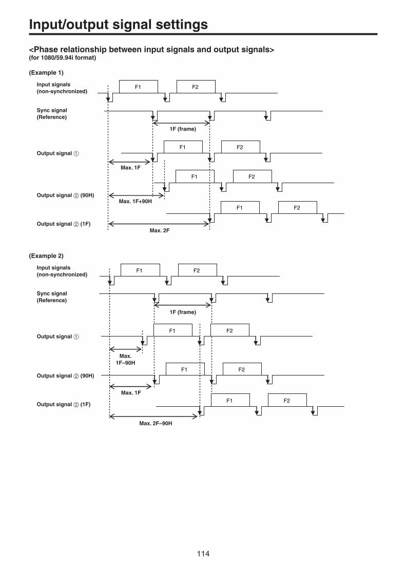
114
Input/output signal settings
<Phase relationship between input signals and output signals>(for 1080/59.94i format)
(Example 1)
F1 F2
F1 F2
F1 F2
F1 F2
Input signals (non-synchronized)
1F (frame)
Sync signal (Reference)
Output signal 1
Output signal 2 (90H)
Output signal 2 (1F)
Max. 1F
Max. 2F
Max. 1F+90H
(Example 2)
F1 F2
F1 F2
F1 F2
F1 F2
Input signals (non-synchronized)
1F (frame)
Sync signal (Reference)
Output signal 1
Output signal 2 (90H)
Output signal 2 (1F)
Max. 1F–90H
Max. 2F–90H
Max. 1F

115
Input/output signal settings
Setting the multi view display
Setting the screen layout
You can select one of the following 10 patterns for the screen layout.The multi view display of this unit supports MV1 and MV2.You can select one of these to display on the built-in display.
4Split 5-aSplit 5-bSplit 6-aSplit 6-bSplit
9Split 10-aSplit 10-bSplit 12Split 16Split
Display of the following signals can be assigned to sub scens 1 to 16.
Signals that can be assignedIN1, IN2, SDI IN3 to 8, IN-A1 to 4, IN-B1 to 4, Black, CBGD1, CBGD2, Still1V, Still1K, Still2V, Still2K, Clip1V, Clip1K, Clip2V, Clip2K, PGM, PVW, CLN, ME PGM, Key Out, MV1, MV2, AUX1 to 4, Clock
1Press the XPTMV button to light its indicator, and display the Multi View Display menu.
2Use [F1] to display the MV Split sub menu.
3Use [F2] to set the split-screen display mode using the Split item.
4Use [F3] to set the size mode for the split screen in the Size item.
Fit The sizes of the split frame and the split screen will be the same.
SQ The sizes of the split frame and the split screen will be smaller, and the material name, level meter, etc., are displayed on the outside of the split screen.
5Use [F1] to display the MV Pattern 1/4 to MV Pattern 4/4 sub menus.
6Use [F2] to [F5] to set the names of the signals to be displayed on the sub screens (1 to 16).
pWhen an input signal (IN1, IN2, SDI IN3 to 8, IN-A1 to 4, IN-B1 to 4) is selected, the display of the material name set in Input menu Name sub menu depends on the characters or symbols used. pWhen AUX buses (AUX1 to 4) are selected as the input signal, the material name displayed inside [ ] depends on the characters and symbols.
pWhen the AUX bus for which “MV” has been selected is displayed on the sub screen of the multi view display, the images are looped as if two mirrors were facing each other.
p 12 split frames cannot be selected for 720p.
<Display modes>
43
2121
53 4 21
53 421
64 53 21
64 53
4Split 5-aSplit 5-bSplit 6-aSplit 6-bSplit
7 8 9
4 5 6
1 2 31
3 4 5 6
7 8 9 10
2
1
3 4 5 6
7 8 9 10
2
21
653 4 7
11108 9 12
1 2 3 4
5 6 7 8
9 10 11 12
13 14 15 16
9Split 10-aSplit 10-bSplit 12Split 16Split

116
Input/output signal settings
Setting the split frame and characters
Set the frame, character brightness and background of the split screens to be displayed on the multi view display.
1Press the XPTMV button to light its indicator, and display
the Multi View Display menu.
2Use [F1] to display the MV Frame sub menu.
3Use [F2] to set the split frame brightness and split frame display using the Frame item.
LUM0%, LUM25%, LUM50%, LUM75%, LUM100%
Select one of these settings for the brightness of the split frame (gray scale).
Off The split frame is not displayed.
4Use [F3] to set the character brightness and character display using the Character item.
LUM0%, LUM25%, LUM50%, LUM75%, LUM100%
Select one of these character (gray scale) brightness settings.
Off The characters are not displayed. Neither is the character background shown.
5Use [F4] to set whether the character background (half-tone) is to be displayed using the Label item.
On The character background is displayed.
Off The character background is not displayed.
p This is enabled when Fit mode is on.
Setting the tally displays
Set the tally displays to be superimposed onto the split frame of the multi view display.You can set 4 tally groups on this unit, and you can set materials for each of the groups.Tally groups 1 and 2 can be displayed on the multi view display.
1Press the CONFSYS button to light its indicator, and display
the System menu.
2Use [F1] to display the Tally MV Color sub menu.
Group1 Fixed to Red.
Group2 Fixed to Green.
3Use [F1] to display the Tally Target sub menu.
4Use [F2] to [F5] to select the material to allocate to Group1 to 4.
PGM Program video signal
PVW Preview video signal
CLN Clean signal
ME PGM ME program video signal
KeyOut Key output signal
AUX1 AUX1 bus output signal
AUX2 AUX2 bus output signal
AUX3 AUX3 bus output signal
AUX4 AUX4 bus output signal
5Press the XPTMV button to light its indicator, and display
the Multi View Display menu.
6Use [F1] to display the Tally Group 1 / 2 sub menu.
p Groups 1 and 2 set in 1 to 4 above can be set to display on the multi view display.

117
Input/output signal settings
7Use [F2] to [F4] to set the tally displays to overlay on the split frame of the multi view display.
IN1
Box
Label Left Label Right
On Tally displays are displayed.
Off No tally displays are shown.
Changing the material names
The material names of the input signals (SDI IN1 to SDI IN8, IN-A1, IN-A2, IN-B1, IN-B2) to be set on the multi view display can be changed.These names can be selected from the default settings or user settings.
1Press the INOUT button to light its indicator, and display
the Input menu.
2Use [F1] to display the Input sub menu.
3Use [F2] to select the input to be set using the Select item. Refer to “Input signal settings”.
4Use [F1] to display the Name sub menu.
5Use [F2] to select the type of material names using the Type item.
Default(default settings)
The following material names are selected automatically. SDI IN1 to SDI IN8, IN-A1, IN-A2, IN-B1, IN-B2
User(user settings)
The material names are set using up to 32 characters.
User type setting procedure
1On the Name sub menu, use [F2] to select “User” using the Type item.
2Press [F3] to display the keyboard screen.
3Use [F1] to [F3], the positioner, the rotary encoders, and the number keys to enter a name, then press [F4]. To clear the name which has been input and close the keyboard screen, press [F5]. Refer to “Keyboard screen operations”.
Setting the level meters
Level meters for the embedded audio signals transferred by the SDI/HDMI input can be displayed on the split screens.
Left display: Channel 1 of group 1Right display: Channel 2 of group 1
1Press the XPTDSBL button to light its indicator, and display
the Multi View Display menu.
2Use [F1] to display the Display sub menu.
3Use [F2] to set the level meter display using the Level Meter item.
On The level meters are displayed.
Off The level meters are not displayed.
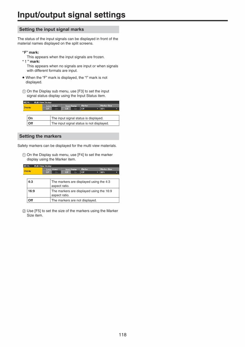
118
Input/output signal settings
Setting the input signal marks
The status of the input signals can be displayed in front of the material names displayed on the split screens.
“F” mark: This appears when the input signals are frozen.“ ! ” mark: This appears when no signals are input or when signals
with different formats are input.
pWhen the “F” mark is displayed, the “!” mark is not displayed.
1On the Display sub menu, use [F3] to set the input signal status display using the Input Status item.
On The input signal status is displayed.
Off The input signal status is not displayed.
Setting the markers
Safety markers can be displayed for the multi view materials.
1On the Display sub menu, use [F4] to set the marker display using the Marker item.
4:3 The markers are displayed using the 4:3 aspect ratio.
16:9 The markers are displayed using the 16:9 aspect ratio.
Off The markers are not displayed.
2Use [F5] to set the size of the markers using the Marker Size item.

119
Input/output signal settings
Ancillary settings for the AUX bus, PGM, and PVW
Set the function that passes through the V ancillary data and embedded audio data of the SDI/HDMI input signal.
1Press the CONFSYS button to light its indicator, and display
the System menu.
2Use [F1] to display the Ancillary sub menu.
Setting for the output signals of the AUX buses (AUX1 to AUX4)
3Use [F2] to select “ON” or “OFF” using the AUX item.
OFF The ancillary data and embedded audio of the AUX bus (AUX1 to 4) outputs are not passed through.
ON The ancillary data and embedded audio of the AUX bus (AUX1 to 4) outputs are passed through.
Setting for the program output signals
4Use [F3] to select “ON” or “OFF” using the PGM item.
OFF The ancillary data and embedded audio of the PGM outputs are not passed through.
ON The ancillary data and embedded audio of the PGM outputs are passed through.
Setting for the preview output signals
5Use [F4] to select “ON” or “OFF” using the PVW item.
OFF The ancillary data and embedded audio of the PVW outputs are not passed through.
ON The ancillary data and embedded audio of the PVW outputs are passed through.
Setting for the output signals of the multi view display
6Use [F5] to select “PGM”, “PVW” or “OFF” using the MV item.
PGM The ancillary data and embedded audio of the PGM are passed through to all MV outputs.
PVW The ancillary data and embedded audio of the PVW are passed through to all MV outputs.
OFF The ancillary data and the embedded audio are not passed through any MV outputs.
pp If Key and DSK are combined, the audio from them are also superimposed.pp When the AUX setting is ON, the DSK1 audio
that is superimposed on AUX1 is simultaneously superimposed on AUX1 for output. Similarly, the DSK2 audio that is superimposed on AUX2 is simultaneously superimposed on AUX2 for output.pp VANC data is not passed if the format of the input
signal is different to the system format.
Notes

120
System settings
Setting the system format
One system format (input/output signal) can be selected.
Do not change the format during any of the following operations:ppWhen reading from a memory card or saving to a memory cardppWhen restoring data from video memory or saving data to internal storageppWhen recording moving images or still imagesppWhen moving images are playing
1Press the CONFSYS button to light its indicator, and display
the System menu.
2Use [F1] to display the Format sub menu.
3Use [F2], select the format using the Format item, and press the [F2] to enter the selection.
Switcher mode settings
1From the Format sub menu, use [F3] to select either 2K or 4K in the Switcher item, then press [F3] to confirm the selection.
pWhen the Switcher mode is changed from either 2K to 4K or from 4K to 2K, a dialog is displayed, so press [F1] to restart the unit. The menu values are initialized after restart.
Dynamic range and color range settings
1From the Format sub menu, use [F4] to select the dynamic range and color range of the image signals handled by this unit in the Color Space item, then press [F4] to confirm the selection.
HDR BT.2020 The dynamic range is HDR and color range operates as BT.2020.
HDR BT.709 The dynamic range is HDR and color range operates as BT.709.
SDR BT.709 The dynamic range is SDR and color range operates as BT.709.

121
System settings
Setting the crosspoints
Assigning signals to the crosspoints
External video input signals and internally generated signals can be assigned to crosspoint buttons 1 to 24.When one of the crosspoint buttons 1 to 24 is held down, the status of the signal assigned is displayed on the built-in display while the button is held down.
Changing the current assignment of the signals selected by the crosspoint buttons will cause the positions of the lit crosspoint buttons to change to correspond with the assignment change. The images output at this time will remain unchanged.
The table below lists the materials which can be assigned.
SignalWhat appears on the
displayDescription
IN1, IN2 IN1, IN2 SDI/HDMI input 1, 2
SDI IN3 to SDI IN8 SDI IN3 to SDI IN8 SDI input 3 to 8
IN-A1 to 4, IN-B1 to 4
IN-A1 to 4, IN-B1 to 4
Option slot (SDI, HDMI)
Black BLK Internally generated signal (black)
CBGD1, CBGD2 CBGD1, CBGD2 Internally generated signal (color background)
CBAR CBAR Internally generated signal (color bar)
Still1V, Still1K, Still2V, Still2K
Still1V, Still1K, Still2V, Still2K
Still image video memory
Clip1V, Clip1K, Clip2V, Clip2K
Clip1V, Clip1K, Clip2V, Clip2K
Moving image video memory
CLN CLN CLN (AUX bus and built-in display images only)
KeyOut KeyOut KeyOut (AUX bus and built-in display images only)
ME PGM ME PGM ME PGM (AUX bus and built-in display images only)
Shift SHIFT SHIFT function
None None No assignment
p The image will not be changed by pressing any button to which “None” is assigned.
The table below lists the default settings.
ButtonWhat appears on
the displayButton
What appears on the display
ButtonWhat appears on
the display
XPT1 IN1 XPT9 CBAR XPT17 None
XPT2 IN2 XPT10 CBGD1 XPT18 None
XPT3 SDI IN 3 XPT11 CBGD2 XPT19 None
XPT4 SDI IN 4 XPT12 None XPT20 None
XPT5 SDI IN 5 XPT13 None XPT21 None
XPT6 SDI IN 6 XPT14 None XPT22 None
XPT7 SDI IN 7 XPT15 None XPT23 None
XPT8 SDI IN 8 XPT16 None XPT24 None

122
System settingsSetting the crosspoint switching
The timing at which the crosspoints are to be switched can be set.This switching involves the operations of the crosspoint buttons and [Cut] button.
1Press the XPTMV button to light its indicator, and display
the XPT menu.
2Use [F1] to display the XPT Switch sub menu.
3Use [F2], and select the switching timing using the Timing item.
Any The crosspoints are switched in the nearest field. This is suited to live applications.
Field1 The crosspoints are switched in field 1. This is suited to editing applications.
Field2 The crosspoints are switched in field 2. This is suited to editing applications.

123
System settings
Button assignments
Setting the user buttons
The user can assign several functions which can be set using the menu items into eight user buttons (U1 to U8).The user buttons light in amber when the assigned function is ON and are off when the assigned function is OFF. Each time the user button is pressed, the function setting alternates between ON and OFF.
The table below lists the functions which can be assigned to the user buttons (U1 to U8).
Function name Description of function
KEY1 PVW Output the KEY1 image to the preview output.
KEY2 PVW Output the KEY2 image to the preview output.
KEY3 PVW Output the KEY3 image to the preview output.
DSK1 PVW Output the DSK1 image to the preview output.
DSK2 PVW Output the DSK2 image to the preview output.
GPII-EN Enables or disables GPI-In.
GPIO-EN Enables or disables GPI-Out.
SHIFT Switches all the A/B bus and AUX bus crosspoints between front and rear.
AUX TRANS Enables or disables the AUX bus transitions.
AUX1 TRANS Enables or disables the AUX1 bus transitions.
AUX2 TRANS Enables or disables the AUX2 bus transitions.
DSK1 on AUX1 Adds DSK to the AUX1 output.
DSK2 on AUX2 Adds DSK to the AUX2 output.
Effect Dissolve Switches effect dissolve between ON and OFF.
Macro Attach Switches macro attach between ON and OFF.
Dissolve Nothing is assigned.
w Default settings
Button Function name Button Function name
U1 KEY1 PVW U5 DSK2 PVW
U2 KEY2 PVW U6 AUX Trans
U3 KEY3 PVW U7 Effect Dissolve
U4 DSK1 PVW U8 SHIFT
<Setting method>
1Press the CONFSYS button to light its indicator, and display
the Config menu.
2Use [F1] to display the User Button1 sub menu and User Button2 sub menu.
p User Button1 to 4 sub menu
3Use [F2] to select the function to be assigned to the [U1] button using the User1 item.
4Use [F3] to select the function to be assigned to the [U2] button using the User2 item.
5Use [F4] to select the function to be assigned to the [U3] button using the User3 item.
6Use [F5] to select the function to be assigned to the [U4] button using the User4 item.
p User Button5 to 8 sub menu
7Use [F2] to select the function to be assigned to the [U5] button using the User5 item.
8Use [F3] to select the function to be assigned to the [U6] button using the User6 item.
9Use [F4] to select the function to be assigned to the [U7] button using the User7 item.
Use [F5] to select the function to be assigned to the [U8] button using the User8 item.
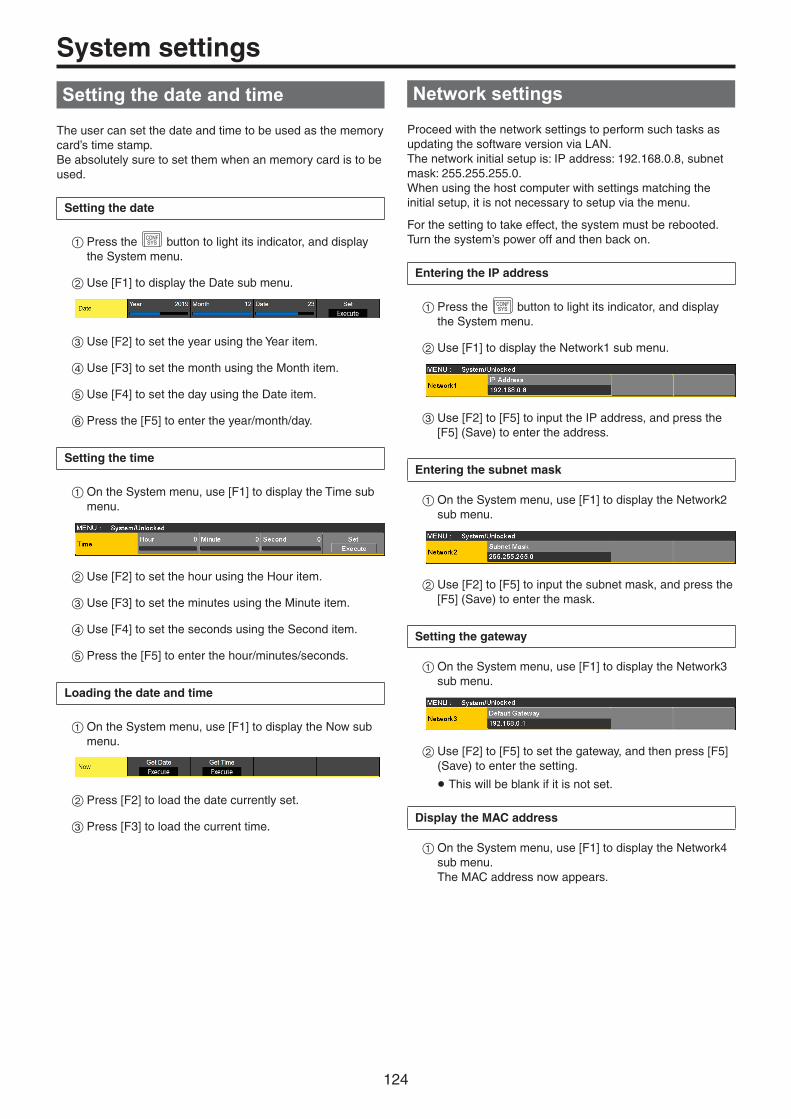
124
System settings
Setting the date and time
The user can set the date and time to be used as the memory card’s time stamp. Be absolutely sure to set them when an memory card is to be used.
Setting the date
1Press the CONFSYS button to light its indicator, and display
the System menu.
2Use [F1] to display the Date sub menu.
3Use [F2] to set the year using the Year item.
4Use [F3] to set the month using the Month item.
5Use [F4] to set the day using the Date item.
6Press the [F5] to enter the year/month/day.
Setting the time
1On the System menu, use [F1] to display the Time sub menu.
2Use [F2] to set the hour using the Hour item.
3Use [F3] to set the minutes using the Minute item.
4Use [F4] to set the seconds using the Second item.
5Press the [F5] to enter the hour/minutes/seconds.
Loading the date and time
1On the System menu, use [F1] to display the Now sub menu.
2Press [F2] to load the date currently set.
3Press [F3] to load the current time.
Network settings
Proceed with the network settings to perform such tasks as updating the software version via LAN.The network initial setup is: IP address: 192.168.0.8, subnet mask: 255.255.255.0. When using the host computer with settings matching the initial setup, it is not necessary to setup via the menu.
For the setting to take effect, the system must be rebooted. Turn the system’s power off and then back on.
Entering the IP address
1Press the CONFSYS button to light its indicator, and display
the System menu.
2Use [F1] to display the Network1 sub menu.
3Use [F2] to [F5] to input the IP address, and press the [F5] (Save) to enter the address.
Entering the subnet mask
1On the System menu, use [F1] to display the Network2 sub menu.
2Use [F2] to [F5] to input the subnet mask, and press the [F5] (Save) to enter the mask.
Setting the gateway
1On the System menu, use [F1] to display the Network3 sub menu.
2Use [F2] to [F5] to set the gateway, and then press [F5] (Save) to enter the setting.
p This will be blank if it is not set.
Display the MAC address
1On the System menu, use [F1] to display the Network4 sub menu. The MAC address now appears.

125
System settings
Setting the built-in display backlight and button illumination
Setting the built-in display backlight
The built-in display backlight can be set to ON or OFF.It is also possible to automatically turn off the built-in display backlight when no control panel operation is performed within a set time interval.
1Press the CONFSYS button to light its indicator, and display
the Config menu.
2Use [F1] to display the LCD Backlight sub menu.
3Use [F2] to select the setting for the backlight using the Light item.
On Backlight is turned on all the time.
Off The backlight turns off as soon as “Off” is selected as the setting.It lights up when the control panel is operated.(The “On” status is selected as the setting.)
60, 120, 180 When no control panel operation is performed within a set time interval (60 minutes, 120 minutes, 180 minutes), the built-in display backlight is turned off automatically.Even when the set time interval elapses and the display backlight is turned off, the backlight comes back on when a control panel operation is performed.
4Use [F3] to set the brightness of the backlight using the Adjust item.
Setting the button illumination
The button indicators in the areas listed below can be kept illuminated all the time. It is then easier to read the characters displayed on the buttons even when the unit is operated in dark places.
p Memory/wipe pattern/number key area p User button area p Display area p Crosspoint area p Transition area
1Press the CONFSYS button to light its indicator, and display
the Config menu.
2Use [F1] to display the Button Illumination sub menu.
3Use [F2] to make settings for the memory/wipe pattern/number key area, the user button area, and the display area in the Dimmer item.
Off The button illumination does not light.
80% to 150% The button illumination lights. Brightness can be adjusted between 80% and 150%.
4Use [F3] to make settings for the button selected in the Lighting item.
80% to 150% The button illumination lights. Brightness can be adjusted between 80% and 150%.
5Use [F4] to make settings for the button when off in the XPT Color item.
Input Make the button illumination light white.
Color Group1 to 8
8 different colors can be set.
6Use [F5] to make settings for the button when off in the Transition Color item.
Input Make the button illumination light white.
Color Group1 to 8
8 different colors can be set.
7Use [F1] to display the Button Color Group1 sub menu.
8Use [F2] to [F4] to set the [R], [G], and [B] for button illumination.
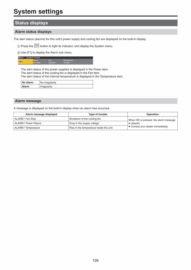
126
System settings
Status displays
Alarm status displays
The alert status (alarms) for this unit’s power supply and cooling fan are displayed on the built-in display.
1Press the CONFSYS button to light its indicator, and display the System menu.
2Use [F1] to display the Alarm sub menu.
The alert status of the power supplies is displayed in the Power item.The alert status of the cooling fan is displayed in the Fan item.The alert status of the internal temperature is displayed in the Temperature item.
No Alarm No irregularity
Alarm Irregularity
Alarm message
A message is displayed on the built-in display when an alarm has occurred.
Alarm message displayed Type of trouble Operation
ALARM ! Fan Stop Shutdown of the cooling fan When OK is pressed, the alarm message is cleared.p Contact your dealer immediately.
ALARM ! Power Failure Drop in the supply voltage
ALARM ! Temperature Rise in the temperature inside the unit

127
System settingsDisplaying information about the version and optional units
Display information about the versions of software and hardware in the unit and the versions of the optional units that are connected.
Displaying the version information
1Press the CONFSYS button to light its indicator, and display
the System menu.
2Use [F1] to display the System Version sub menu.
p The unit’s system version information is displayed in the System Version item.
Displaying information for optional units
3Use [F1] to display the Option sub menu.
4Use [F2] to select the option slot using the Select item.
SLOT A Option slot A
SLOT B Option slot B
5The types of the optional units connected are displayed in the Slot A/Slot B item.
p “None” is displayed when there is no connection.

128
System settings
Initialization
Initializing setting data
Initialization returns the set data to the factory shipment status.When settings data is initialized, video memory that has been saved to internal storage is lost.
<Items and data which are not initialized> p The items of the System menu listed below: Network1, Network2, Network3, Date, Time
1Press the CONFSYS button to light its indicator and display
the System menu.
2Use [F1] to display the Initial sub menu.
3Press [F2] to proceed with the initializing.
4When initializing, use [F1] to select “Yes” and press the [F1]. When not initializing, use [F5] to select “No” and press the [F5].
Initializing fader
The range for executing a transition can be initialized by operating the fader lever.Initialization should be performed when transitions are not completed to the end even when the fader lever has been moved as far as it will go.
1Press [F3] in the Initial sub menu to perform initialization.
2When initializing, use [F1] to select “Yes” and press the [F1]. When not initializing, use [F5] to select “No” and press the [F5].

129
Remote camera link functions
It is possible to connect a maximum of 16 remote cameras to this unit via LAN and remote control them.The remote cameras that can be connected are as follows (as of May 2020):
pp AW-UE150 seriespp AW-HR140 seriespp AW-HE130 series
pp AW-HN130 seriespp AW-UE70 seriespp AW-UN70 series
pp AW-HE40 seriespp AW-HN40 seriespp AW-HE42 series
Refer to the following Web site for details.https://pro-av.panasonic.net/
wpExamples of connections
SDI/HDMI video signals
Switching hub
LAN cables
Live SwitcherAV-UHS500
Monitor 1
Monitor 2
Monitor Monitor
LAN cables
Remote camera controller
External DC power supply
External DC power supply
LAN connector
Remote camera (maximum 16)
pp Use a GbE compatible switching hub and Cat5e or better STP LAN cables for the connection between the unit and the remote cameras.pp Furthermore, use a network design so that the IP addresses for the unit and the remote cameras are within the same subnet.

130
Remote camera link functions
The control functions for the remote cameras connected to this unit are as follows:pp IP address automatic detectionpp A maximum of 100 preset memories can be played back and registeredpp Pan and tilt of each connected remote camera can be controlled with the positioner on this unitpp Zoom of each connected remote camera can be controlled with the encoders on this unitpp Focus and iris of each connected remote camera can be controlled with the encoders on this unitpp Control of pan, tilt, zoom, focus, and iris can be individually disabledpp Images of remote cameras connected to this unit can be adjustedWhite balance/AWB/ABB/Gain/R Gain/B Gain/Pedestalpp On-screen menus of remote cameras connected to this unit can be displayed and operatedpp The remote cameras connected to this unit can be switched between ON and standby as a group or individuallypp It is possible to tally control connected remote cameras linked to the tally status of this unitpp Errors on remote cameras connected to this unit can be detected
Settings for connections to remote cameras
Selecting the terminals for remote camera connection
1Press the INOUT button to light its indicator and display
the Input menu.
2Use [F1] to display the Input sub menu.
3Press [F2] and select the input signal to which the remote camera is connected in the Select item.
p The following remote camera settings are possible according to the input to IN1 and 2, SDI IN 3 to 8, IN-A1 to 4, and IN-B1 to 4.
IP address settings
To set automatically
You can scan for the IP addresses set in the connected remote cameras and set them in this unit.
1Use [F1] to display the Camera Settings1 sub menu.
2Use [F5] to execute the Scan IP Address item to scan for the IP addresses of connected remote cameras.
p The scan results are displayed in the list of the IP address item. pWhen “Select From List” is displayed, use [F2] and select the IP address of the connected remote camera in the IP address item.
p “Not Detected” is displayed if the IP address of the remote camera could not be detected.
p Modify the IP address of the unit or the remote camera and set so that there is no duplication. p The “Duplicate IP Address Detected. (ErrNo = – 650)” error message is displayed if the IP address of the remote camera is duplicated.

131
Remote camera link functions
To set manually
You can directly set the IP addresses set in the connected remote cameras in this unit.
1Use [F1] to display the Camera Settings1 sub menu.
2Use [F4] to execute the Edit IP Address item, then enter the IP addresses of connected remote cameras.
Remote camera port settings
3From the Camera Settings1 sub menu, use [F3] to set the port to which the remote camera is connected in the Port item.
Remote camera authentication settings
1Use [F1] to display the Camera Settings2 sub menu.
2Use [F2] to execute the Edit User Name item and set the user name used for authentication with the remote camera.
3Use [F3] to execute the Edit Password item, then set the password used for authentication with the remote camera.
Checking the remote camera connection status
1Use [F1] to display the Camera Settings2 sub menu.
2The camera name set on the remote camera is displayed in the Name item.
3The IP connection status of the unit and the remote cameras is displayed in the Network Status item.
No IP Address
The IP address of the camera has not been entered in the Input menu.
Now Checking…
The unit and the remote camera are communicating.
Connected The unit and the remote camera are connected.
Unauthorized Authentication information has not been entered or is incorrect.
Not Connected
There is a communication error.

132
Remote camera link functions
Remote camera operation direction settings
You can use the positioner and encoders of this unit to control the pan, tilt, zoom, focus, and iris of remote cameras connected to this unit.The settings for the operation direction are made as follows:
1Use [F1] to display the Camera Settings3 sub menu.
2The pan control direction for the remote camera using the positioner of this unit is set in the Pan Direction item.
Normal The operation direction of the positioner and the direction of image movement are the same.
Reverse The operation direction of the positioner and the direction of image movement are the opposite.
3The tilt control direction for the remote camera using the positioner of this unit is set in the Tilt Direction item.
Normal The operation direction of the positioner and the direction of image movement are the same.
Reverse The operation direction of the positioner and the direction of image movement are the opposite.
4Use [F1] to display the Camera Settings4 sub menu.
5The zoom control direction for the remote camera using [F1]/[F2]/[F3]/[Z] operations of this unit is set in the Zoom Direction item.
Normal Zoom moves to the telephoto end when [F1] is pressed.Zoom moves to the wide end when [F2] is pressed.Zoom moves to the telephoto end when [F3]/[Z] is turned clockwise.Zoom moves to the wide end when [F3]/[Z] is turned counterclockwise.
Reverse Zoom moves to the wide end when [F1] is pressed.Zoom moves to the telephoto end when [F2] is pressed.Zoom moves to the wide end when [F3]/[Z] is turned clockwise.Zoom moves to the telephoto end when [F3]/[Z] is turned counterclockwise.
6The focus control direction for the remote camera using [F4] operations of this unit is set in the Focus Direction item.
Normal Focus moves to the far side with a clockwise turn.Focus moves to the near side with a counterclockwise turn.
Reverse Focus moves to the near side with a clockwise turn.Focus moves to the far side with a counterclockwise turn.
7The iris control direction for the remote camera using [F5] operations of this unit is set in the Iris Direction item.
Normal The iris opens with a clockwise turn.The iris closes with a counterclockwise turn.
Reverse The iris closes with a clockwise turn.The iris opens with a counterclockwise turn.
Remote camera tally control settings
You can link the red tally control of remote cameras connected to this unit to the red tally control of this unit.
1Use [F1] to display the Camera Settings3 sub menu.
2Set the link between the red tally control on this unit and the red tally control on the remote camera in the Tally (Group1) item.
Enable Linked.
Disable Not linked.

133
Remote camera link functions
Selecting the cameras to be operated
By connecting remote cameras to this unit, you can control remote cameras using the positioner and encoders of this unit.
1Assign the remote cameras connected to XPT. Refer to “Selecting the terminals for remote camera connection” for information on how to assign.
2Press the [DISP/CAM] button to make it turn green.
KEY1F/S
KEY2F/S
KEY3F/S
DSK1F/S
DSK2F/S
MV1MV2
PGMPVW
DISPCAM
AUX BUS DELEGATION AUX /DISP SOURCEAMBER : FILL / GREEN : SOURCE
AUX1
AUX
AUX2 AUX3 AUX4
SHIFT
XPT2
3Select the remote cameras assigned in Step 1 as the CAM bus sources.
p The selected buses turn green.
The inputs that can be selected as the CAM bus sources are the following inputs. XPTs other than these cannot be selected.
· IN1 to IN2· SDI IN3 to SDI IN8· IN-A1 to IN-A4· IN-B1 to IN-B4
p Control of remote cameras is available only when either the [CAM PMEM] screen or [CAM CONT] screen is being displayed.
4The pan and tilt on the remote camera connected to this unit are controlled by moving the positioner up, down, left, and right.
VMEM
BKGDPATT
CAMCONT
KEYPATT
MENUHOLD
PRJSD Card
ALARMLINK
ZZOOM
X/YPAN/TLT
Lights
5Turning [Z] left and right adjusts the control speed for pan/tilt and operates the zoom.
You can switch the control speed and zoom operation by pressing [Z].

134
Remote camera link functions
Controlling in the camera control screen
When remote cameras are connected to this unit, you can control them in the camera control screen while displaying the input images from the selected camera on the built-in LCD.
1While the unit is connected to the remote camera, press the CAMCONT button.
2The display on the built-in display of this unit changes, and the [CAM CONT] button turns amber.
F1 F2 F3 F4 F5
A Input source information display The following information is displayed:The CAM bus source material name/camera name/(camera model name)/camera statusThe name set on the remote camera is displayed as the camera name.
Camera status
Power On Normal situation
Pan & Tilt Alarm When a problem is detected with the pan/tilt of the camera
Fan Alarm When a problem is detected with the fan of the camera
Other Alarm When a problem is detected with something other than the pan/tilt or fan of the camera
Camera IP Connection Error When the camera failed to connect via IP
No IP Address for Camera When the IP address has not been set for the camera corresponding to the input signal
Now Connecting to Camera… When connecting to the camera for the first time after switching the input signal
Standby When the camera is on standby
B Z-Dial Indicates the application for [Z].Each time you press [Z], operation switches between P-T Speed and Zoom.
P-T Speed Indicates the status of the control speed of pan/tilt. “Fast” indicates fast operation and “Slow” indicates slow operation.
Zoom Indicates the zoom position. “Tele” indicates the telephoto side and “Wide” indicates the wide side.
Focus Indicates the focus position. “Far” indicates the far side and “Near” indicates the near side.“Auto” is displayed when auto focus is on.
Iris Indicates the iris status. “Open” indicates that the iris is open and “Close” indicates that the iris is closed.“Auto“ is displayed when the auto iris is on.
C [F1] Zoom moves to the telephoto end at a constant speed when the button is pressed. An explanation is also displayed on the Menu screen.
D [F2] Zoom moves to the wide end at a constant speed when the button is pressed. An explanation is also displayed on the Menu screen.
E [F3] Turn left and right to operate the zoom. Zoom to the wide end with a counterclockwise turn and to the telephoto end with a clockwise turn.An explanation is also displayed on the Menu screen.
F [F4] Turn left and right to operate the focus. Focus moves to the near side with a counterclockwise turn and to the far side with a clockwise turn.Focus switches between auto and manual when the button is pressed.An explanation is also displayed on the Menu screen.
G [F5] Turn left and right to operate the iris. The iris closes with a counterclockwise turn and the iris opens with a clockwise turn.Iris switches between auto and manual when the button is pressed.An explanation is also displayed on the Menu screen.
p If control of the remote cameras is disabled, explanations for F1 to F5 are not displayed.
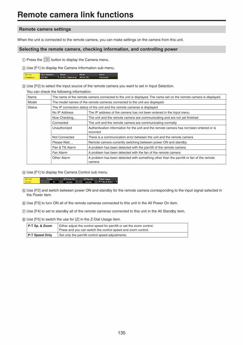
135
Remote camera link functions
Remote camera settings
When the unit is connected to the remote camera, you can make settings on the camera from this unit.
Selecting the remote camera, checking information, and controlling power
1Press the TIMECAM button to display the Camera menu.
2Use [F1] to display the Camera Information sub menu.
3Use [F2] to select the input source of the remote camera you want to set in Input Selection.
You can check the following information.Name The name of the remote camera connected to the unit is displayed. The name set on the remote camera is displayed.
Model The model names of the remote cameras connected to the unit are displayed.
Status The IP connection status of the unit and the remote cameras is displayed.
No IP Address The IP address of the camera has not been entered in the Input menu
Now Checking… The unit and the remote camera are communicating and are not yet finished
Connected The unit and the remote camera are communicating normally
Unauthorized Authentication information for the unit and the remote camera has not been entered or is incorrect
Not Connected There is a communication error between the unit and the remote camera
Please Wait… Remote camera currently switching between power ON and standby
Pan & Tilt Alarm A problem has been detected with the pan/tilt of the remote camera
Fan Alarm A problem has been detected with the fan of the remote camera
Other Alarm A problem has been detected with something other than the pan/tilt or fan of the remote camera
4Use [F1] to display the Camera Control sub menu.
5Use [F2] and switch between power ON and standby for the remote camera corresponding to the input signal selected in the Power item.
6Use [F3] to turn ON all of the remote cameras connected to this unit in the All Power On item.
7Use [F4] to set to standby all of the remote cameras connected to this unit in the All Standby item.
8Use [F5] to switch the use for [Z] in the Z-Dial Usage item.
P-T Sp. & Zoom Either adjust the control speed for pan/tilt or set the zoom control.Press and you can switch the control speed and zoom control.
P-T Speed Only Set only the pan/tilt control speed adjustments.

136
Remote camera link functions
Remote camera control speed settings
You can set the pan/tilt control, zoom control speed, focus control speed, and iris control speed for remote cameras connected to this unit.The adjustments can be made in 32 steps, with the control speed increasing the higher the number.
1Press the TIMECAM button to display the Camera menu.
2Use [F1] to display the Control Speed sub menu.
3Use [F2] to set the pan/tilt control speed in the Pan & Tilt item.
4Use [F3] to set the zoom control speed in the Zoom item.
5Use [F4] to set the focus control speed in the Focus item.
6Use [F5] to set the iris control speed in the Iris item.
Remote camera on-screen menu and color bar settings
1Press the TIMECAM button to display the Camera menu.
2Use [F1] to display the OSD Menu & Color Bars sub menu.
3Use [F2] to set the display of the on-screen menu of the remote camera in the OSD Menu item.
On Displayed.
Off Not displayed.
4You can use [F3] to operate the on-screen menus of the remote camera in the Menu Operation item.
Counterclockwise turn
Moves the cursor up.
Clockwise turn Moves the cursor down.
Press Confirmed.
5Use [F4] to set the output images from the remote camera in the color bar in the Color Bars item.
On The color bar is set.Set the type of color bar on the camera.
Off Normal image is set.

137
Remote camera link functions
Remote camera lens control settings
1Press the TIMECAM button to display the Camera menu.
2Use [F1] to display the Lens Control sub menu.
3Use [F2] to set the auto focus of the remote camera in the Auto Focus item.
On Auto Focus
Off Manual Focus
4Use [F3] to set the auto iris of the remote camera in the Auto Iris item.
On Auto Iris
Off Manual Iris
p The operation explanation on the camera control screen is as follows.
When Auto Focus/Auto Iris is “Off”:
When Auto Focus/Auto Iris is “On”:
Remote camera image adjustment settings
1Press the TIMECAM button to display the Camera menu.
2Use [F1] to display the AWB sub menu.
3Use [F4] to set the automatic white balance adjustment mode in the AWB Mode item.
4Use [F2] to execute the automatic white balance adjustments.
5The result of the adjustment is displayed in the Last AWB Result item.
Successful Successful.
Failed Failed.
— When this unit is starting up or the input signal has been changed
6Use [F1] to display the ABB sub menu.
7Use [F2] to execute the automatic black balance adjustments.
8The result of the adjustment is displayed in the Last ABB Result item.
Successful Successful.
Failed Failed.
— When this unit is starting up or the input signal has been changed
9Use [F1] to display the Gain1/Gain2/Pedestal sub menus.
Use [F2] to [F5] to set each of the items.
p Refer to the operating instructions for the connected remote camera for details about the setting values.

138
Remote camera link functions
Remote camera preset memory playback settings
1Press the TIMECAM button to display the Camera menu.
2Use [F1] to display the Preset Settings sub menu.
3Use [F2] to [F5] to set each of the items.
p Refer to the operating instructions for the connected remote camera for details about the setting values.
Disabling remote camera control
You can individually disable the control of the pan/tilt, zoom, focus, and iris for remote cameras connected to this unit.
1Press the TIMECAM button to display the Camera menu.
2Use [F1] to display the Lock sub menu.
3Use [F2] to set the pan/tilt control and speed adjustment control enable/disable of the remote camera in the Pan & Tilt Lock item.
On Disable
Off Enable
pWhen Lock is engaged and you press either the CAMPMEM
button or the CAMCONT button, “ ” is displayed above
“P-T Speed” at the right of the built-in display.
4Use [F3] to set the zoom control and speed adjustment control enable/disable of the remote camera in the Zoom Lock item.
On Disable
Off Enable
pWhen Lock is engaged and you press either the CAMPMEM
button or the CAMCONT button, “ ” is displayed above
“Zoom” at the right of the built-in display. p The [F1]/[F2] operation descriptions will be blank. p “ZOOM LOCKED” is displayed in the [F3] operation description.
5Use [F4] to set the focus control and speed adjustment control enable/disable of the remote camera in the Focus Lock item.
On Disable
Off Enable
pWhen Lock is engaged and you press either the CAMPMEM
button or the CAMCONT button, “ ” is displayed above
“Focus” at the right of the built-in display. p “FOCUS LOCKED” is displayed in the [F4] operation description.
6Use [F5] to set the iris control and speed adjustment control enable/disable of the remote camera in the Iris Lock item.
On Disable
Off Enable
pWhen Lock is engaged and you press either the CAMPMEM
button or the CAMCONT button, “ ” is displayed above
“Iris” at the right of the built-in display. p “IRIS LOCKED” is displayed in the [F5] operation description.

139
Remote camera link functions
Controlling in the camera preset memory screen
When remote cameras are connected to this unit, you can control them in the camera preset screen while displaying the thumbnail image of the selected camera preset memory on the built-in LCD.
1Press the CAMPMEM button.
2The display on the built-in LCD of the unit switches.
p It is possible to save, play back, and delete preset memories using the number keys. p Zoom control is possible using [F1] to [F3]. p It is possible to change the preset scope/preset speed using [F4]/[F5].
You can store up to a maximum of 100 preset memories in the remote cameras connected to this unit.pp They are not stored in this unit.
100 preset memories are divided between 10 pages, so 10 preset memories can be saved in 1 page.If there is a preset memory that corresponds to the number key, the LED of the number key lights.The number key that corresponds to the preset memory that was recalled last on this unit turns amber and all others turn green.
You can select the operation for the preset memory each time you press the [STORE]/[RECALL]/[DEL] buttons.ppWhile the [STORE] button is lit red, you can store preset memories by holding down the number keys.ppWhile the [RECALL] button is lit amber, you can execute preset memories by pressing the number keys.ppWhile the [DEL] button is lit red, you can delete preset memories by holding down the number keys.
STORE
DELMACRO
EDIT
SHOTMEM
KEY1F/S
KEY2F/S
KEY3F/S
DSK1F/S
DSK2F/S
MV1MV2
PGMPVW
DISPCAM
XPTDSBL
TAKEENTER
7NEW
8COPY
9PASTE
4INS
5DEL
6MOD
1<
2>
3REV
0/10<<
.>>
CUNDO
CAMPMEM
EVENTMEM
-/+PAGE
RECALL
MENU
MEMORY / WIPE PATTERN / 10 KEY
AUX BUS DELEGATION AUX /DISP SOURCEAMBER : FILL / GREEN : SOURCE
STILL 1 STILL 2 TRIM IN REC
CLIP 1 CLIP 2 TRIM OUT
<
F1 F2 F3
AUX1
AUX
AUX2 AUX3 AUX4 MACRO
BKGD KEYSHIFT
MIX MIX
F4 F5
> REV
<< >> TRIM OFF PLAY
STOP
DISPLAY
pp Changing the preset scope/preset speed
pp PMEM operation selection pp Execute operations corresponding to PMEM
pp Switching of the camera that is the target of operation by the CAM bus
pp Zoom control

140
Remote camera link functions
F1 F2 F3 F4 F5
A Input source information display The following information is displayed.The CAM bus source material name/camera name/(camera model name)/camera statusThe name set on the remote camera is displayed as the camera name.
Camera status
Power On Normal situation
Pan & Tilt Alarm When a problem is detected with the pan/tilt of the camera
Fan Alarm When a problem is detected with the fan of the camera
Other Alarm When a problem is detected with something other than the pan/tilt or fan of the camera
Camera IP Connection Error When the camera failed to connect via IP
No IP Address for Camera When the IP address has not been set for the camera corresponding to the input signal
Now Connecting to Camera… When connecting to the camera for the first time after switching the input signal
Standby When the camera is on standby
B Z-Dial Indicates the application for [Z].Each time you press [Z], operation switches between P-T Speed and Zoom.
P-T Speed Indicates the status of the control speed of pan/tilt. “Fast” indicates fast operation and “Slow” indicates slow operation.
Zoom Indicates the zoom position. “Tele” indicates the telephoto side and “Wide” indicates the wide side.
Focus Indicates the focus position. “Far” indicates the far side and “Near” indicates the near side.“Auto” is displayed when auto focus is on.
Iris Indicates the iris status. “Open” indicates that the iris is open and “Close” indicates that the iris is closed.“Auto” is displayed when the auto iris is on.
C [F1] Zoom moves to the telephoto end at a constant speed when the button is pressed.
D [F2] Zoom moves to the wide end at a constant speed when the button is pressed.
E [F3] Turn left and right to operate the zoom. Zoom to the wide end with a counterclockwise turn and to the telephoto end with a clockwise turn.
F [F4] Turn left and right to operate the preset targets.Preset targets can be switched between the following 3 modes.
Mode A Set the pan/tilt, zoom, focus, iris, gain, and white balance that are the targets of presetting.
Mode B Set the pan/tilt, zoom, focus, and iris that are the targets of presetting.
Mode C Set the pan/tilt, zoom, and focus that are the targets of presetting.
G [F5]
1 Minimum speed (When set to the pan/tilt operating time: 99)
20 Default value (When set to the pan/tilt operating time: 20)
30 Maximum speed (When set to the pan/tilt operating time: 1)
p The screen displays here show the models that support thumbnails (AW-UE150 series). Other models will not display thumbnails, with icons displayed instead. p It is not possible to set the pan/tilt operating time for all of the remote cameras. Refer to the user guide for the remote camera for details.
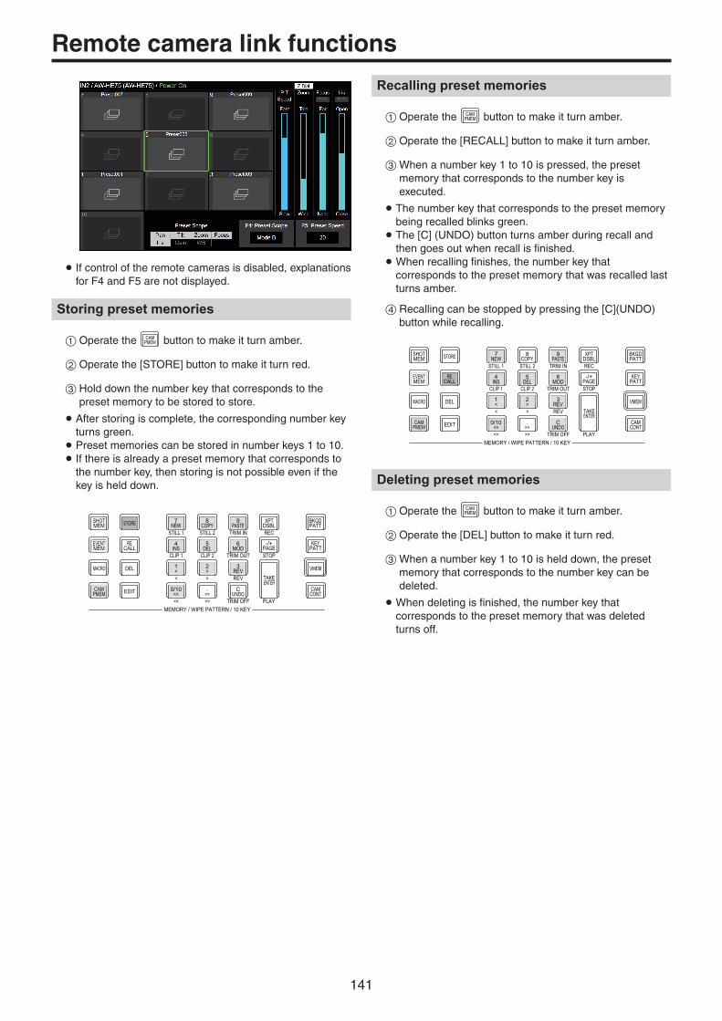
141
Remote camera link functions
p If control of the remote cameras is disabled, explanations for F4 and F5 are not displayed.
Storing preset memories
1Operate the CAMPMEM button to make it turn amber.
2Operate the [STORE] button to make it turn red.
3Hold down the number key that corresponds to the preset memory to be stored to store.
p After storing is complete, the corresponding number key turns green.
p Preset memories can be stored in number keys 1 to 10. p If there is already a preset memory that corresponds to the number key, then storing is not possible even if the key is held down.
STORE
DEL VMEMMACRO
EDIT
SHOTMEM
BKGDPATT
XPTDSBL
TAKEENTER
7NEW
8COPY
9PASTE
4INS
5DEL
6MOD
1<
2>
3REV
0/10<<
.>>
CUNDO
CAMPMEM
CAMCONT
EVENTMEM
KEYPATT
-/+PAGE
RECALL
MEMORY / WIPE PATTERN / 10 KEY
STILL 1 STILL 2 TRIM IN REC
CLIP 1 CLIP 2 TRIM OUT
< > REV
<< >> TRIM OFF PLAY
STOP
Recalling preset memories
1Operate the CAMPMEM button to make it turn amber.
2Operate the [RECALL] button to make it turn amber.
3When a number key 1 to 10 is pressed, the preset memory that corresponds to the number key is executed.
p The number key that corresponds to the preset memory being recalled blinks green. p The [C] (UNDO) button turns amber during recall and then goes out when recall is finished. pWhen recalling finishes, the number key that corresponds to the preset memory that was recalled last turns amber.
4Recalling can be stopped by pressing the [C](UNDO) button while recalling.
STORE
DEL VMEMMACRO
EDIT
SHOTMEM
BKGDPATT
XPTDSBL
TAKEENTER
7NEW
8COPY
9PASTE
4INS
5DEL
6MOD
1<
2>
3REV
0/10<<
.>>
CUNDO
CAMPMEM
CAMCONT
EVENTMEM
KEYPATT
-/+PAGE
RECALL
MEMORY / WIPE PATTERN / 10 KEY
STILL 1 STILL 2 TRIM IN REC
CLIP 1 CLIP 2 TRIM OUT
< > REV
<< >> TRIM OFF PLAY
STOP
Deleting preset memories
1Operate the CAMPMEM button to make it turn amber.
2Operate the [DEL] button to make it turn red.
3When a number key 1 to 10 is held down, the preset memory that corresponds to the number key can be deleted.
pWhen deleting is finished, the number key that corresponds to the preset memory that was deleted turns off.

142
Remote camera link functions
Selecting a page of preset memories
1Operate the CAMPMEM button to make it turn amber.
2Page selection starts when the [PAGE] button is pressed.
p The [PAGE] button turns amber when a page is selected. Number keys 1 to 10 correspond to page numbers 1 to 10.
3Use the number keys 1 to 10 or the [PAGE] button to complete selection of the page.
p If a number key 1 to 10 is pressed, the current page number changes to the value of the pressed number key. pWhen the [PAGE] button is pressed, the current page number is not changed.
4If there is at least one preset memory in the page, the LED of the number key that corresponds to the page lights.
p The number key that corresponds to the current page turns amber and all the other pages light green. p In the example in the figure below, page numbers 1, 5, 6, 7, 8, and 10 each contain at least one preset memory, and page number 1 is the current page.
STORE
DEL VMEMMACRO
EDIT
SHOTMEM
BKGDPATT
XPTDSBL
TAKEENTER
7NEW
8COPY
9PASTE
4INS
5DEL
6MOD
1<
2>
3REV
0/10<<
.>>
CUNDO
CAMPMEM
CAMCONT
EVENTMEM
KEYPATT
-/+PAGE
RECALL
MEMORY / WIPE PATTERN / 10 KEY
STILL 1 STILL 2 TRIM IN REC
CLIP 1 CLIP 2 TRIM OUT
< > REV
<< >> TRIM OFF PLAY
STOP
p The targets for project file storing and macro recording are as shown in the below table.Storing project files Selections with the STORE/RECALL/DEL buttons,
Preset page numbers for input signals (for each connected camera)
Macro recording targets Storing preset memories,Recalling preset memories,Deleting preset memories,Stopping with the [C](UNDO) button when recalling preset memories, Selections with the [STORE]/[RECALL]/[DEL] buttons when recalling preset memories, Page selections when recalling preset memories,Changing Preset Scope, Changing Preset Speed

143
External interfaces
Setting the GPI I/O
The user can set the functions that are to be controlled from the GPI ports and set whether to enable the control.
1Press the CONFSYS button to light its indicator, and display
the Config menu.
2Use [F1] to display the GPI-In Setting sub menu (or GPI-Out Setting sub menu).
3Use [F2] to set “On” or “Off” for the control to be exercised from the ports using the GPI-In Enable item (or GPI-Out Enable item).
4Use [F3] to set the AUX bus to be used to notify the tally using the AUX Sel item.
5Use [F1] to display GPI-In Port 1/2 sub menu and GPI-In Port 2/2 sub menu (or GPI-Out Port 1/5 sub menu to GPI-Out Port 5/5 sub menu).
6Use [F2] to [F5] to allocate the functions to be assigned to the respective pin numbers. Refer to “Control using the GPI Input port” and
“Output from the GPI Output port”.
p Settings for the GPI-In Enable (or GPI-Out Enable) item can be assigned to one of the user buttons. Refer to “Setting the user buttons”.

144
External interfaces
w Control using the GPI Input port
Assign Item Description of function assigned Control method
AUTO AUTO button in transition area
Operations are performed using contact inputs (30 ms or more).
CUT CUT button in transition area
KEY ON KEY1 to KEY3 button in transition area
DSK ON DSK1, DSK2 button in transition area
FTB FTB button in transition area
BKGD AUTO AUTO button when the background is selected
BKGD CUT CUT button when the background is selected
KEY AUTO AUTO button when the key is selected
KEY CUT CUT button when the key is selected
REC Still1 Still1 recording
REC Still2 Still2 recording
REC Clip1 Clip1 recording start
REC Clip2 Clip2 recording start
STOP Clip1 Clip1 recording stop or playback stop
STOP Clip2 Clip2 recording stop or playback stop
PLAY Clip1 Clip1 playback start
PLAY Clip2 Clip2 playback start
AUX XPT1 to 24
Crosspoint buttons (1 to 24) used to switch the AUX buses.p Select the AUX buses (AUX1 to AUX4) to be controlled using the
menu.
TlyG1 DSBL Red tally signal is not output Functions are enabled using contact inputs (or disabled in open status).
TlyG2 DSBL Green tally signal is not output
AUXTly DSBL AUX tally signal is not output
No Assign No function assigned

145
External interfaces
w Output from the GPI Output port
Assign Item Description of function assigned Output
CUT Cut transition executed
Low pulses are output (approx. 50 to 60 ms).
KEY ON Key transition start
DSK ON DSK transition start
FTB ON FTB transition start
BKGD CUT Cut transition for the background executed
KEY CUT Cut transition for a key executed
EVENTMEM Event set by event memory executed
AUTO Auto transition execution in progress
A low level is output.
BKGD AUTO Auto transition execution in progress for background
KEY AUTO Auto transition execution in progress for key
KEY Trans Transition execution in progress for key
DSK Trans Transition execution in progress for DSK
FTB Trans Transition execution in progress for FTB
TlyG1 SDI IN1 to SDI IN8 Red tally for SDI IN1 to SDI IN8
A low level is output during tally output.
TlyG1 HDMI IN1 to HDMI IN2 Red tally for HDMI IN1 to HDMI IN2
TlyG1 IN-A1 to IN-A4 Red tally for IN-A1 to IN-A4
TlyG1 IN-B1 to IN-B4 Red tally for IN-B1 to IN-B4
TlyG2 SDI IN1 to SDI IN8 Green tally for SDI IN1 to SDI IN8
TlyG2 HDMI IN1 to HDMI IN2 Green tally for HDMI IN1 to HDMI IN2
TlyG2 IN-A1 to IN-A4 Green tally for IN-A1 to IN-A4
TlyG2 IN-B1 to IN-B4 Green tally for IN-B1 to IN-B4
AUXTly SDI IN1 to SDI IN8 When SDI IN1 to SDI IN8* have been selected by the AUX bus
A low level is output while the inputs are selected.
AUXTly HDMI IN1 to HDMI IN2 When HDMI IN1 to HDMI IN2* have been selected by the AUX bus
AUXTly IN-A1 to IN-A4 When IN-A1 to IN-A4* have been selected by the AUX bus
AUXTly IN-B1 to IN-B4 When IN-B1 to IN-B4* have been selected by the AUX bus
No Assign No function assigned
*: Select the AUX buses (AUX1 to AUX4) whose signals are to be output using the menu.

146
External interfaces
Com
GPI OutALARM Out
Example of GPI Out and ALARM connectionsEnsure that the conditions given below are satisfied.
Dielectric strength: Max. DC 24 VCurrent: Max. 50 mA
AV-UHS500 (Max. voltage: 24 V)
Tally LED(Max. current: 50 mA)
Com
GPI In
+3.3 V
Example of GPI In connectionsProvide contact inputs.
AV-UHS500
TALLY/GPI 1
12345
12 11 10
678
15 14 13 9
TALLY/GPI 2
12345
12 11 10
678
15 14 13 9
Pin No. Signal name Pin No. Signal name
1 GPI-Out1 1 GPI-Out10
9 GPI-Out9 9 GPI-Out18
2 GPI-Out2 2 GPI-Out11
10 ALARM Out 10 GPI-Out19
3 GPI-Out3 3 GPI-Out12
11 GPI-In1 11 GPI-In5
4 GPI-Out4 4 GPI-Out13
12 GPI-In2 12 GPI-In6
5 GPI-Out5 5 GPI-Out14
13 GPI-In3 13 GPI-In7
6 GPI-Out6 6 GPI-Out15
14 GPI-In4 14 GPI-In8
7 GPI-Out7 7 GPI-Out16
15 GPI-Com 15 GPI-Com
8 GPI-Out8 8 GPI-Out17
LAN
Connect the unit and computer or the unit and an external device*.*: An external device can be controlled from the unit.
pp Use a LAN cable (category 5e or above).

147
External interfaces
Controlling with external panels
With this unit, you can perform the following operations from external panels (*) connected via an IP network:pp Select materials for each buspp Execute video transitionspp Play back macro memoriespp Play back shot memories
*: This unit supports the LBP series from LAWO. Consult LAWO for LBP series settings and operations.
Preparations
Use a LAN cable to connect the external panel to the LAN connector on the back of the unit.It is possible to connect a maximum of 20 external panels. When connecting multiple external panels, connect via a hub.
External panel settings
Check the following settings on this unit, then make the settings on the connected external panels:
pp System menu Network1 sub menu Take the address value set in the IP Address item of this sub menu and set it as the IP address of the device that will be the target of the external panel operations.
pp System menu ExtPanel Info sub menu Take the port number set in the Port No item of this sub menu and set it as the port number of the device that will be the target of the external panel operations.
Also set the subnet mask (Network2 sub menu) and the default gateway (Network3 sub menu) according to the network environment connected.
Settings on this unit when external panels are connected
Receiving port number settings
1Press the CONFSYS button to light its indicator, and display
the System menu.
2Use [F1] to display the ExtPanel Info sub menu.
3Press [F2] to enable/disable the external panel function in the Disable/Enable item.
4Use [F3] to set the receiving port number used by this unit.
Possible setting range 62000 to 65535
Default value 62010
Shot memory playback target settings
Set the playback targets for when shot memories of this unit are played back by operations on the external panels.
1Press the CONFSYS button to light its indicator, and display
the System menu.
2Use [F1] to display the ExtPanelIP SMEMRecall1/2 sub menu.
3Use [F2] to [F4] to set the playback targets for the shot memory.
p ME, DSK, AUX, color background, and crosspoint area can be individually turned ON/OFF.

148
External interfaces
List of bus IDs and source IDs
When operations are performed on external panels, crosspoint setting commands are issued that specify the materials (Source) for the buses (Destination).When this unit receives the crosspoint setting command from the external panel, materials are selected and video transitions are executed according to the bus and material combinations specified in the command.This section describes the IDs (numbers) used by this unit to identify each bus and each material.
IDs can be categorized broadly into the following 2 types:
1) Normal bus IDs and material IDsIDs that specify the buses inside the switcher (ME1PGM, AUX1, etc.) and the switcher materials (SDI IN1, CBGD1, STILL1-V, etc.).Use a number between 1 and 512.
2) Extended bus IDs and extended material IDsIDs used for playback of video transitions, macro memories, and shot memories.When this unit receives a crosspoint setting command in which the same extended ID is specified for the bus and the material, the corresponding function is executed.For example, when a command is received that specifies the ME1 AUTO material (ID: 522) for the ME1 AUTO bus (ID: 522), an AUTO transition is executed at ME1.Use a number between 513 and 1023.
Executable operations Specified bus and material
ME key transition ME1 KEY1 AUTO to ME1 KEY3 AUTO
ME key transition (CUT) ME1 KEY1 CUT to ME1 KEY3 CUT
ME AUTO transition ME1 BKGD AUTO
ME CUT transition ME1 BKGD CUT
DSK transition DSK1 AUTO to DSK2 AUTO
DSK transition (CUT) DSK1 CUT to DSK2 CUT
Playing back macro registered memories MACROPLAY1-1 to MACROPLAY10-10
Playing back shot memory registered memories SHOTPLAY1-1 to SHOTPLAY10-10
pp Consult LAWO for details on how to assign IDs to the operations of each of the buttons on the LBP series.

149
External interfaces
Bus IDID Bus ID Bus ID Bus ID Bus ID Bus
1 ME1PGM 100 DSK2-S 149 – 162 MV1-10 176 MV2-8
2 ME1PVW 101 – 150 VMEM-V 163 MV1-11 177 MV2-9
3 ME1KEY1-F ⋮ 151 VMEM-K 164 MV1-12 178 MV2-10
4 ME1KEY1-S 112 – 152 – 165 MV1-13 179 MV2-11
5 ME1KEY2-F 113 AUX1 ⋮ 166 MV1-14 180 MV2-12
6 ME1KEY2-S 114 AUX2 153 MV1-1 167 MV1-15 181 MV2-13
7 ME1KEY3-F 115 AUX3 154 MV1-2 168 MV1-16 182 MV2-14
8 ME1KEY3-S 116 AUX4 155 MV1-3 169 MV2-1 183 MV2-15
9 – 117 – 156 MV1-4 170 MV2-2 184 MV2-16
⋮ ⋮ 157 MV1-5 171 MV2-3 185 –
96 – 140 – 158 MV1-6 172 MV2-4 ⋮97 DSK1-F 141 DISP 159 MV1-7 173 MV2-5 512 –
98 DSK1-S 142 – 160 MV1-8 174 MV2-6
99 DSK2-F ⋮ 161 MV1-9 175 MV2-7
–: Unused ID
Source IDID Source ID Source ID Source ID Source ID Source
1 IN1 148 BLACK 165 MV1 ⋮ 252 –
2 IN2 149 STILL1V 166 MV2 208 – ⋮3 SDI_IN3 150 STILL1K 167 – 209 ME PGM 539 –
4 SDI_IN4 151 STILL2V ⋮ 210 – 540 OPA_IN1
5 SDI_IN5 152 STILL2K 170 – ⋮ 541 OPA_IN2
6 SDI_IN6 153 – 171 Key Out 226 – 542 OPA_IN3
7 SDI_IN7 ⋮ 172 CLN 227 AUX1 543 OPA_IN4
8 SDI_IN8 157 CLIP1V 173 – 228 AUX2 544 OPB_IN1
9 – 158 CLIP1K ⋮ 229 AUX3 545 OPB_IN2
⋮ 159 CLIP2V 200 – 230 AUX4 546 OPB_IN3
144 – 160 CLIP2K 201 PGM 231 – 547 OPB_IN4
145 CBGD1 161 – 202 – ⋮ 548 –
146 CBGD2 ⋮ 203 PVW 250 – ⋮147 CBAR 164 – 204 – 251 CLOCK 553 –
–: Unused ID

150
External interfaces
Extended bus IDID Bus ID Bus ID Bus ID Bus ID Bus
513 – 633 MACROPLAY3-4 679 MACROPLAY7-10 725 SHOTPLAY2-6 771 SHOTPLAY7-2
514 ME1 KEY1 AUTO 634 MACROPLAY3-5 680 MACROPLAY8-1 726 SHOTPLAY2-7 772 SHOTPLAY7-3
515 ME1 KEY2 AUTO 635 MACROPLAY3-6 681 MACROPLAY8-2 727 SHOTPLAY2-8 773 SHOTPLAY7-4
516 ME1 KEY3 AUTO 636 MACROPLAY3-7 682 MACROPLAY8-3 728 SHOTPLAY2-9 774 SHOTPLAY7-5
517 – 637 MACROPLAY3-8 683 MACROPLAY8-4 729 SHOTPLAY2-10 775 SHOTPLAY7-6
518 ME1 KEY1 CUT 638 MACROPLAY3-9 684 MACROPLAY8-5 730 SHOTPLAY3-1 776 SHOTPLAY7-7
519 ME1 KEY2 CUT 639 MACROPLAY3-10 685 MACROPLAY8-6 731 SHOTPLAY3-2 777 SHOTPLAY7-8
520 ME1 KEY3 CUT 640 MACROPLAY4-1 686 MACROPLAY8-7 732 SHOTPLAY3-3 778 SHOTPLAY7-9
521 – 641 MACROPLAY4-2 687 MACROPLAY8-8 733 SHOTPLAY3-4 779 SHOTPLAY7-10
522 ME1 BKGD AUTO 642 MACROPLAY4-3 688 MACROPLAY8-9 734 SHOTPLAY3-5 780 SHOTPLAY8-1
523 ME1 BKGD CUT 643 MACROPLAY4-4 689 MACROPLAY8-10 735 SHOTPLAY3-6 781 SHOTPLAY8-2
524 – 644 MACROPLAY4-5 690 MACROPLAY9-1 736 SHOTPLAY3-7 782 SHOTPLAY8-3
⋮ 645 MACROPLAY4-6 691 MACROPLAY9-2 737 SHOTPLAY3-8 783 SHOTPLAY8-4
593 – 646 MACROPLAY4-7 692 MACROPLAY9-3 738 SHOTPLAY3-9 784 SHOTPLAY8-5
594 DSK1 AUTO 647 MACROPLAY4-8 693 MACROPLAY9-4 739 SHOTPLAY3-10 785 SHOTPLAY8-6
595 DSK2 AUTO 648 MACROPLAY4-9 694 MACROPLAY9-5 740 SHOTPLAY4-1 786 SHOTPLAY8-7
596 – 649 MACROPLAY4-10 695 MACROPLAY9-6 741 SHOTPLAY4-2 787 SHOTPLAY8-8
597 – 650 MACROPLAY5-1 696 MACROPLAY9-7 742 SHOTPLAY4-3 788 SHOTPLAY8-9
598 DSK1 CUT 651 MACROPLAY5-2 697 MACROPLAY9-8 743 SHOTPLAY4-4 789 SHOTPLAY8-10
599 DSK2 CUT 652 MACROPLAY5-3 698 MACROPLAY9-9 744 SHOTPLAY4-5 790 SHOTPLAY9-1
600 – 653 MACROPLAY5-4 699 MACROPLAY9-10 745 SHOTPLAY4-6 791 SHOTPLAY9-2
⋮ 654 MACROPLAY5-5 700 MACROPLAY10-1 746 SHOTPLAY4-7 792 SHOTPLAY9-3
609 – 655 MACROPLAY5-6 701 MACROPLAY10-2 747 SHOTPLAY4-8 793 SHOTPLAY9-4
610 MACROPLAY1-1 656 MACROPLAY5-7 702 MACROPLAY10-3 748 SHOTPLAY4-9 794 SHOTPLAY9-5
611 MACROPLAY1-2 657 MACROPLAY5-8 703 MACROPLAY10-4 749 SHOTPLAY4-10 795 SHOTPLAY9-6
612 MACROPLAY1-3 658 MACROPLAY5-9 704 MACROPLAY10-5 750 SHOTPLAY5-1 796 SHOTPLAY9-7
613 MACROPLAY1-4 659 MACROPLAY5-10 705 MACROPLAY10-6 751 SHOTPLAY5-2 797 SHOTPLAY9-8
614 MACROPLAY1-5 660 MACROPLAY6-1 706 MACROPLAY10-7 752 SHOTPLAY5-3 798 SHOTPLAY9-9
615 MACROPLAY1-6 661 MACROPLAY6-2 707 MACROPLAY10-8 753 SHOTPLAY5-4 799 SHOTPLAY9-10
616 MACROPLAY1-7 662 MACROPLAY6-3 708 MACROPLAY10-9 754 SHOTPLAY5-5 800 SHOTPLAY10-1
617 MACROPLAY1-8 663 MACROPLAY6-4 709 MACROPLAY10-10 755 SHOTPLAY5-6 801 SHOTPLAY10-2
618 MACROPLAY1-9 664 MACROPLAY6-5 710 SHOTPLAY1-1 756 SHOTPLAY5-7 802 SHOTPLAY10-3
619 MACROPLAY1-10 665 MACROPLAY6-6 711 SHOTPLAY1-2 757 SHOTPLAY5-8 803 SHOTPLAY10-4
620 MACROPLAY2-1 666 MACROPLAY6-7 712 SHOTPLAY1-3 758 SHOTPLAY5-9 804 SHOTPLAY10-5
621 MACROPLAY2-2 667 MACROPLAY6-8 713 SHOTPLAY1-4 759 SHOTPLAY5-10 805 SHOTPLAY10-6
622 MACROPLAY2-3 668 MACROPLAY6-9 714 SHOTPLAY1-5 760 SHOTPLAY6-1 806 SHOTPLAY10-7
623 MACROPLAY2-4 669 MACROPLAY6-10 715 SHOTPLAY1-6 761 SHOTPLAY6-2 807 SHOTPLAY10-8
624 MACROPLAY2-5 670 MACROPLAY7-1 716 SHOTPLAY1-7 762 SHOTPLAY6-3 808 SHOTPLAY10-9
625 MACROPLAY2-6 671 MACROPLAY7-2 717 SHOTPLAY1-8 763 SHOTPLAY6-4 809 SHOTPLAY10-10
626 MACROPLAY2-7 672 MACROPLAY7-3 718 SHOTPLAY1-9 764 SHOTPLAY6-5 810 –
627 MACROPLAY2-8 673 MACROPLAY7-4 719 SHOTPLAY1-10 765 SHOTPLAY6-6 ⋮628 MACROPLAY2-9 674 MACROPLAY7-5 720 SHOTPLAY2-1 766 SHOTPLAY6-7 1024 –
629 MACROPLAY2-10 675 MACROPLAY7-6 721 SHOTPLAY2-2 767 SHOTPLAY6-8
630 MACROPLAY3-1 676 MACROPLAY7-7 722 SHOTPLAY2-3 768 SHOTPLAY6-9
631 MACROPLAY3-2 677 MACROPLAY7-8 723 SHOTPLAY2-4 769 SHOTPLAY6-10
632 MACROPLAY3-3 678 MACROPLAY7-9 724 SHOTPLAY2-5 770 SHOTPLAY7-1 –: Disabled ID (-1) sent

151
External interfaces
Extended Source IDID Source ID Source ID Source ID Source ID Source
513 – 633 MACROPLAY3-4 679 MACROPLAY7-10 725 SHOTPLAY2-6 771 SHOTPLAY7-2
514 ME1 KEY1 AUTO 634 MACROPLAY3-5 680 MACROPLAY8-1 726 SHOTPLAY2-7 772 SHOTPLAY7-3
515 ME1 KEY2 AUTO 635 MACROPLAY3-6 681 MACROPLAY8-2 727 SHOTPLAY2-8 773 SHOTPLAY7-4
516 ME1 KEY3 AUTO 636 MACROPLAY3-7 682 MACROPLAY8-3 728 SHOTPLAY2-9 774 SHOTPLAY7-5
517 – 637 MACROPLAY3-8 683 MACROPLAY8-4 729 SHOTPLAY2-10 775 SHOTPLAY7-6
518 ME1 KEY1 CUT 638 MACROPLAY3-9 684 MACROPLAY8-5 730 SHOTPLAY3-1 776 SHOTPLAY7-7
519 ME1 KEY2 CUT 639 MACROPLAY3-10 685 MACROPLAY8-6 731 SHOTPLAY3-2 777 SHOTPLAY7-8
520 ME1 KEY3 CUT 640 MACROPLAY4-1 686 MACROPLAY8-7 732 SHOTPLAY3-3 778 SHOTPLAY7-9
521 – 641 MACROPLAY4-2 687 MACROPLAY8-8 733 SHOTPLAY3-4 779 SHOTPLAY7-10
522 ME1 BKGD AUTO 642 MACROPLAY4-3 688 MACROPLAY8-9 734 SHOTPLAY3-5 780 SHOTPLAY8-1
523 ME1 BKGD CUT 643 MACROPLAY4-4 689 MACROPLAY8-10 735 SHOTPLAY3-6 781 SHOTPLAY8-2
524 – 644 MACROPLAY4-5 690 MACROPLAY9-1 736 SHOTPLAY3-7 782 SHOTPLAY8-3
⋮ 645 MACROPLAY4-6 691 MACROPLAY9-2 737 SHOTPLAY3-8 783 SHOTPLAY8-4
593 – 646 MACROPLAY4-7 692 MACROPLAY9-3 738 SHOTPLAY3-9 784 SHOTPLAY8-5
594 DSK1 AUTO 647 MACROPLAY4-8 693 MACROPLAY9-4 739 SHOTPLAY3-10 785 SHOTPLAY8-6
595 DSK2 AUTO 648 MACROPLAY4-9 694 MACROPLAY9-5 740 SHOTPLAY4-1 786 SHOTPLAY8-7
596 – 649 MACROPLAY4-10 695 MACROPLAY9-6 741 SHOTPLAY4-2 787 SHOTPLAY8-8
597 – 650 MACROPLAY5-1 696 MACROPLAY9-7 742 SHOTPLAY4-3 788 SHOTPLAY8-9
598 DSK1 CUT 651 MACROPLAY5-2 697 MACROPLAY9-8 743 SHOTPLAY4-4 789 SHOTPLAY8-10
599 DSK2 CUT 652 MACROPLAY5-3 698 MACROPLAY9-9 744 SHOTPLAY4-5 790 SHOTPLAY9-1
600 – 653 MACROPLAY5-4 699 MACROPLAY9-10 745 SHOTPLAY4-6 791 SHOTPLAY9-2
⋮ 654 MACROPLAY5-5 700 MACROPLAY10-1 746 SHOTPLAY4-7 792 SHOTPLAY9-3
609 – 655 MACROPLAY5-6 701 MACROPLAY10-2 747 SHOTPLAY4-8 793 SHOTPLAY9-4
610 MACROPLAY1-1 656 MACROPLAY5-7 702 MACROPLAY10-3 748 SHOTPLAY4-9 794 SHOTPLAY9-5
611 MACROPLAY1-2 657 MACROPLAY5-8 703 MACROPLAY10-4 749 SHOTPLAY4-10 795 SHOTPLAY9-6
612 MACROPLAY1-3 658 MACROPLAY5-9 704 MACROPLAY10-5 750 SHOTPLAY5-1 796 SHOTPLAY9-7
613 MACROPLAY1-4 659 MACROPLAY5-10 705 MACROPLAY10-6 751 SHOTPLAY5-2 797 SHOTPLAY9-8
614 MACROPLAY1-5 660 MACROPLAY6-1 706 MACROPLAY10-7 752 SHOTPLAY5-3 798 SHOTPLAY9-9
615 MACROPLAY1-6 661 MACROPLAY6-2 707 MACROPLAY10-8 753 SHOTPLAY5-4 799 SHOTPLAY9-10
616 MACROPLAY1-7 662 MACROPLAY6-3 708 MACROPLAY10-9 754 SHOTPLAY5-5 800 SHOTPLAY10-1
617 MACROPLAY1-8 663 MACROPLAY6-4 709 MACROPLAY10-10 755 SHOTPLAY5-6 801 SHOTPLAY10-2
618 MACROPLAY1-9 664 MACROPLAY6-5 710 SHOTPLAY1-1 756 SHOTPLAY5-7 802 SHOTPLAY10-3
619 MACROPLAY1-10 665 MACROPLAY6-6 711 SHOTPLAY1-2 757 SHOTPLAY5-8 803 SHOTPLAY10-4
620 MACROPLAY2-1 666 MACROPLAY6-7 712 SHOTPLAY1-3 758 SHOTPLAY5-9 804 SHOTPLAY10-5
621 MACROPLAY2-2 667 MACROPLAY6-8 713 SHOTPLAY1-4 759 SHOTPLAY5-10 805 SHOTPLAY10-6
622 MACROPLAY2-3 668 MACROPLAY6-9 714 SHOTPLAY1-5 760 SHOTPLAY6-1 806 SHOTPLAY10-7
623 MACROPLAY2-4 669 MACROPLAY6-10 715 SHOTPLAY1-6 761 SHOTPLAY6-2 807 SHOTPLAY10-8
624 MACROPLAY2-5 670 MACROPLAY7-1 716 SHOTPLAY1-7 762 SHOTPLAY6-3 808 SHOTPLAY10-9
625 MACROPLAY2-6 671 MACROPLAY7-2 717 SHOTPLAY1-8 763 SHOTPLAY6-4 809 SHOTPLAY10-10
626 MACROPLAY2-7 672 MACROPLAY7-3 718 SHOTPLAY1-9 764 SHOTPLAY6-5 810 –
627 MACROPLAY2-8 673 MACROPLAY7-4 719 SHOTPLAY1-10 765 SHOTPLAY6-6 ⋮628 MACROPLAY2-9 674 MACROPLAY7-5 720 SHOTPLAY2-1 766 SHOTPLAY6-7 1024 –
629 MACROPLAY2-10 675 MACROPLAY7-6 721 SHOTPLAY2-2 767 SHOTPLAY6-8
630 MACROPLAY3-1 676 MACROPLAY7-7 722 SHOTPLAY2-3 768 SHOTPLAY6-9
631 MACROPLAY3-2 677 MACROPLAY7-8 723 SHOTPLAY2-4 769 SHOTPLAY6-10
632 MACROPLAY3-3 678 MACROPLAY7-9 724 SHOTPLAY2-5 770 SHOTPLAY7-1 –: Unused ID

152
External interfaces
External Control
<Overview>It is possible to switch the materials of all buses on the AV-UHS500 and transmit and receive the material name information of all buses on the AV-UHS500 with external devices connected to the network such as system controllers and tally interfaces.It is also possible to switch the Source Link settings (Master/Slave) from external devices.It is possible to transmit and receive tally information and Source ID information using a transmission format that is compatible with TSL UMD Protocol V5.0.By connecting to the Remote Camera Controller AW-RP120 from Panasonic via IP, it is possible to switch material, transmit and receive Tally information, perform focus assist, and acquire material names for the AV-UHS500 buses using the AW-RP120 camera selector.pp Refer to the operating instructions for AW-RP120 for
information about control bus settings, etc.
<Preparation>Use a LAN cable to connect the external device to the LAN connector on the rear of AV-UHS500.The unit supports 20 IP connections. When connecting to multiple external devices, connect via a hub. Set IP address so there is no duplication.You can confirm the AV-UHS500 network settings with <CONF/SYS> button → [SYSTEM] → [NetWork1] tab, [NetWork2] tab.The initial settings are; IP Address: “192.168.0.8”, Subnet Mask: “255.255.255.0”.
<Settings>
1Press the CONFSYS button to light its indicator, and display
the System menu.
2Use [F1] to display the ExtControl Switcher sub menu.
3Press [F2] to enable/disable the External Control function in the Disable/Enable item.
4Use [F3] to set the network in the PortNo item.
5Use [F4] to set the command transmission interval in the IntervalTime item.
6Use [F1] to display the ExtControl AUX Panel1 to 5 sub menu.
7Press [F2] to [F5] to set the IP address of the connected external device.
8Use [F1] to display the ExtControl Aux Panel6 sub menu.
9Use [F2] to set the receiving port number of the connected external device. Set to 60031 when connecting to the Remote Camera Controller AW-RP120.
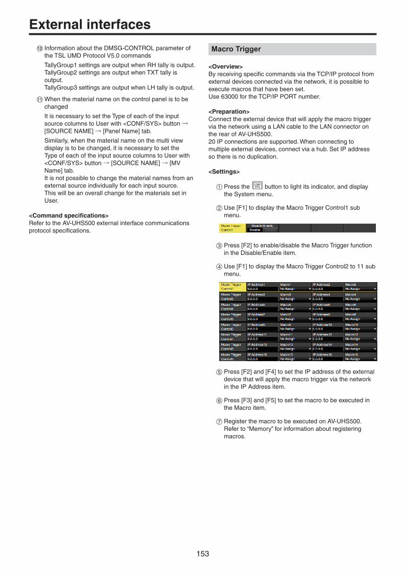
153
External interfaces
Information about the DMSG-CONTROL parameter of the TSL UMD Protocol V5.0 commands
TallyGroup1 settings are output when RH tally is output.TallyGroup2 settings are output when TXT tally is output.TallyGroup3 settings are output when LH tally is output.
When the material name on the control panel is to be changed
It is necessary to set the Type of each of the input source columns to User with <CONF/SYS> button → [SOURCE NAME] → [Panel Name] tab.
Similarly, when the material name on the multi view display is to be changed, it is necessary to set the Type of each of the input source columns to User with <CONF/SYS> button → [SOURCE NAME] → [MV Name] tab.It is not possible to change the material names from an external source individually for each input source. This will be an overall change for the materials set in User.
<Command specifications>Refer to the AV-UHS500 external interface communications protocol specifications.
Macro Trigger
<Overview>By receiving specific commands via the TCP/IP protocol from external devices connected via the network, it is possible to execute macros that have been set.Use 63000 for the TCP/IP PORT number.
<Preparation>Connect the external device that will apply the macro trigger via the network using a LAN cable to the LAN connector on the rear of AV-UHS500.20 IP connections are supported. When connecting to multiple external devices, connect via a hub. Set IP address so there is no duplication.
<Settings>
1Press the CONFSYS button to light its indicator, and display
the System menu.
2Use [F1] to display the Macro Trigger Control1 sub menu.
3Press [F2] to enable/disable the Macro Trigger function in the Disable/Enable item.
4Use [F1] to display the Macro Trigger Control2 to 11 sub menu.
5Press [F2] and [F4] to set the IP address of the external device that will apply the macro trigger via the network in the IP Address item.
6Press [F3] and [F5] to set the macro to be executed in the Macro item.
7Register the macro to be executed on AV-UHS500. Refer to “Memory” for information about registering macros.

154
Appearance
Unit: mm (inch)
U1 U2
PICT
STORE
DEL VMEMMACRO
EDIT
U3
MENUMODE
SHOTMEM
KEY1F/S
PGMA
PSTB
KEY2F/S
KEY3F/S
DSK1F/S
DSK2F/S
MV1MV2
PGMPVW
FTBON
KEY1ON
KEY2ON
KEY3ON
DSK1ON
DSK2ON
DISPCAM
BKGDPATT
XPTDSBL
TAKEENTER
7NEW
8COPY
9PASTE
4INS
5DEL
6MOD
1<
2>
3REV
0/10<<
.>>
CUNDO
CAMPMEM
CAMCONT
EVENTMEM
KEYPATT
-/+PAGE
RECALL
MENUOFF
MENUHOLD
WFMVECT
XPTMV
INOUT
CONFSYS
VMEMMACRO
SHOTEVENT
BKGDCBGD
TIMECAM
PRJSD Card
KEY1CKEY
KEY2KEY3
DSK1DSK2
U4
USER
MENU
MEMORY / WIPE PATTERN / 10 KEY
AUX BUS DELEGATION AUX /DISP SOURCE
1/13 2/14 3/15 4/16 5/17 6/18 7/19 8/20 9/21 10/22 11/23 12/24
AMBER : FILL / GREEN : SOURCE WIPE DIRECTION
STILL 1 STILL 2 TRIM IN REC
CLIP 1 CLIP 2 TRIM OUT
<
F1 F2 F3
AUX1
AUX
AUX2 AUX3 AUX4 MACRO N/R
BKGD KEY
MIX
CUTSHIFT
SHIFT
SHIFT
AUTO
MIX MIX
WIPE
WIPE WIPE
R
F4 F5
> REV
<< >> TRIM OFF PLAY
STOP
DISPLAY
POWER
ALARMLINK
ZZOOM
X/YPAN/TLT
U5 U6 U7 U8
TALLY/GPI 1
EXPANTION SLOT A EXPANTION SLOT B
REF BOOTSV NM
SIGNALGND
POWER
LAN 12G SDI IN 12G SDI OUTHDMI IN HDMI IOUT1 2 3 4 5 11 22 1 23 4 56 7 8
AC IN ~
ON
OFF
TALLY/GPI 2
360
(14-
3/16
)
440 (17-5/16)
130 (5-1/8)
33 (1-5/16)
170 (6-11/16)

155
Specifications
Power supply: AC ( ) 100 V to 240 V, 50/60 Hz
Current consumption: 1.5 A
indicates safety information.
Video connectors
<SDI IN 1> to <SDI IN 8> terminals
8 lines (plus another maximum of 8 lines when using the OPTION unit)pp Connectors: BNC × 8pp Connectors <SDI IN 5> to <SDI IN 8> equipped with up-converters.pp Connectors <SDI IN 5> to <SDI IN 8> equipped with color correctors.pp SDI IN 1/2 excludes HDMI IN 1/2.
12G-SDI 12G-SDI, complied with SMPTE ST 2082-10 standard
3G-SDI 3G-SDI, complied with SMPTE292 standard (Compatible with Level-A/Level-B)
HD-SDI HD-SDI, complied with SMPTE292M standard
<HDMI IN 1> to <HDMI IN 2> terminals
2 lines (plus another maximum of 6 lines when using the OPTION unit)Video format inputs:720p/59.94 Hz, 720p/50 Hz, 1080i/59.94 Hz, 1080i/50 Hz, 1080p/59.94 Hz, 1080p/50 Hz, 1080p/29.97 Hz, 1080p/25 Hz, 1080p/24 Hz, 1080p/23.98 Hz, 2160p/59.94 Hz, 2160p/50 Hz, 2160p/29.97 Hz, 2160p/25 Hz, 2160p/24 Hz, 2160p/23.98 Hzpp Connectors: HDMI × 2pp This connector does not support the CPRM technologies.pp HDMI IN 1/2 excludes SDI IN 1/2.
<SDI OUT 1> to <SDI OUT 5> terminals
5 lines (plus another maximum of 8 lines when using the OPTION unit)pp Connectors: BNC × 5pp PGM, PVW, CLN, ME PGM, MV1 to MV2, AUX1 to AUX4, Key Out can be assigned.
12G-SDI 12G-SDI, complied with SMPTE ST 2082-10 standard
3G-SDI 3G-SDI, complied with SMPTE292 standard (Compatible with Level-A)
HD-SDI HD-SDI, complied with SMPTE292M standard
<HDMI OUT 1> to <HDMI OUT 2> terminals
2 lines (plus another maximum of 6 lines when using the OPTION unit)Video format outputs:720p/59.94 Hz, 720p/50 Hz, 1080i/59.94 Hz, 1080i/50 Hz, 1080p/59.94Hz, 1080p/50 Hz, 2160p/59.94 Hz, 2160p/50 Hz, 2160p/29.97 Hz, 2160p/25 Hz, 2160p/24 Hz, 2160p/23.98 Hzpp Connectors :HDMI × 2pp PGM, PVW, CLN, ME PGM, MV1 to MV2, AUX1 to AUX4, Key Out can be assigned.
Signal formats 2160/59.94P, 50P, 29.97P, 25P, 24P, 23.98P, 1080/59.94P, 50P, 29.97Psf, 25Psf, 24Psf, 23.98Psf, 59.94i, 50i, 720/59.94P, 50P
Signal processing R: G: B 4: 4: 4 10 bit/4: 2: 2 10 bit
Y: PB: PR 4: 2: 2 10 bit
ME number 1ME

156
Synchronizing connectors
<REF> terminal Reference input/ BB outputs
In Genlock mode: Black burst or Tri-level Sync input signals (with loop-through)pp Loop-through output is performed in external sync mode.pp If loop-through output is not going to be used, provide a 75 Ω termination.pp Connectors : BNCpp Same field frequencies as those of the system formats supported.ppWith the 1080/24PsF format, only Genlock mode supported.ppWith the 1080/23.98PsF format, black burst with 10 Field ID (SMPTE318M standard met) or Tri-level Sync signals supported.pp BB signals are output from two connectors in the internal sync mode.
Video delay time 1 line (H) When the frame synchronizer setting is [Off] and neither the up-converter nor the down-converter is operating
1 frame (F) When the frame synchronizer setting is on and the up-converter and down-converter are operating
ppWhen the signals have passed through PinP, DVE, multi view, down-converter or HDMI IN, a maximum delay of 1 frame is applied in each case.
Control connectors
<LAN> terminal Compatible with 1000Base-TX and AUTO-MDIX (For IP control)pp Connecting cable: LAN cable (CAT5E), max. 100 m (328 ft), STP (Shielded Twisted Pair) cable recommendedpp Connectors : RJ-45
<TALLY GPI> terminal INPUT: 8 inputs, general-purpose, photocoupler sensingOUTPUT: 19 outputs, selected from R/G tally, general-purpose ALARM: 1 output, open collector output (negative logic)
Other
Ambient operating temperature
0 °C to 40 °C (32 °F to 104 °F)
Ambient operating humidity
10% to 90% (no condensation)
Storage temperature 0 °C to 40 °C (32 °F to 104 °F)
Storage humidity 10% to 90% (no condensation)
Mass Approx. 7 kg (15.4 lb)
Dimensions
(W × H × D)
440 mm × 170 mm × 360 mm (17-5/16 inches × 6-11/16 inches × 14-3/16 inches) (excluding protrusions)
Specifications

157
Setting menu tablepp Settings for items indicated with () are reflected when the item is selected and [F2], [F3], [F4] or [F5] is pressed.
MenuSub menu Parameter 1 Parameter 2 Parameter 3 Parameter 4
Use [F1] to select. Use [F2] to select. Use [F3] to select. Use [F4] to select. Use [F5] to select.Background Border Parameter Border Width Soft
Setting range On, Off 0.1 to 100.0 0.0 to 100.0
Default value Off 5.0 0.0
Border Color Parameter Hue Sat Lum Load
Setting range 0.0 to 359.9 0.0 to 100.0 0.0 to 108.0 White, Yellow, Cyan, Green, Magenta, Red, Blue, Black
Default value 0.0 0.0 100.0 White
Position Parameter X-Pos Y-Pos Copy To Key1
Setting range � 100.00 to 100.00
� 100.00 to 100.00
Execute
Default value 0.00 0.00
Modify Parameter Trim 4:3 Auto
Setting range Off, 16:9, 4:3, 4:3 Smooth
Off, On
Default value Off Off
3D Modify Parameter Light Size Radius Angle
Setting range On, Off 0.0 to 100.0 0.000 to 1.000 � 45 to 45
Default value Off 100.0 0.500 0
Transition Time
Parameter TransTime WaitTime Wait
Setting range 1s00f to 0s00f 1s00f to 0s00f Off, On
Default value 1s00f 1s00f Off
Transition Margin
Parameter Margin Start End
Setting range Off, On 0.0 to 100.0 0.0 to 100.0
Default value Off 0.0 0.0
Clip Trans Sync Parameter Clip1 Clip2
Setting range Off, AUTO, KEY1 ON, KEY2 ON, KEY3 ON, DSK1 ON, DSK2 ON, FTB ON, Fader
Off, AUTO, KEY1 ON, KEY2 ON, KEY3 ON, DSK1 ON, DSK2 ON, FTB ON, Fader
Default value Off Off

158
MenuSub menu Parameter 1 Parameter 2 Parameter 3 Parameter 4
Use [F1] to select. Use [F2] to select. Use [F3] to select. Use [F4] to select. Use [F5] to select.Color Background CBGD1 Main Parameter Hue Sat Lum Load
Setting range 0.0 to 359.9 0.0 to 100.0 0.0 to 108.0 White, Yellow, Cyan, Green, Magenta, Red, Blue, Black
Default value 120.0 100.0 100.0 Blue
CBGD1 Sub Parameter Hue Sat Lum Load
Setting range 0.0 to 359.9 0.0 to 100.0 0.0 to 108.0 White, Yellow, Cyan, Green, Magenta, Red, Blue, Black
Default value 0.0 0.0 100.0 White
CBGD1 Wash Parameter Wash Color R-Sat R-Lum
Setting range On, Off Dual, Rainbow 0.0 to 100.0 0.0 to 108.0
Default value Off Dual 100.0 100.0
CBGD1 Wave Parameter Pattern Cycle Phase Angle
Setting range Sine, Saw 0 to 100 � 180.0 to 180.0 0.0 to 360.0
Default value Sine 0 0.0 0.0
CBGD1 Move Parameter Move Speed
Setting range Off, Roll, Rotation
� 50.0 to 50.0
Default value Off 1.0
CBGD2 Main Parameter Hue Sat Lum Load
Setting range 0.0 to 359.9 0.0 to 100.0 0.0 to 108.0 White, Yellow, Cyan, Green, Magenta, Red, Blue, Black
Default value 0.0 100.0 100.0 Red
CBGD2 Sub Parameter Hue Sat Lum Load
Setting range 0.0 to 359.9 0.0 to 100.0 0.0 to 108.0 White, Yellow, Cyan, Green, Magenta, Red, Blue, Black
Default value 0.0 0.0 100.0 White
CBGD2 Wash Parameter Wash Color R-Sat R-Lum
Setting range On, Off Dual, Rainbow 0.0 to 100.0 0.0 to 108.0
Default value Off Dual 100.0 100.0
CBGD2 Wave Parameter Pattern Cycle Phase Angle
Setting range Sine, Saw 0 to 100 � 180.0 to 180.0 0.0 to 360.0
Default value Sine 0 0.0 0.0
CBGD2 Move Parameter Move Speed
Setting range Off, Roll, Rotation
� 50.0 to 50.0
Default value Off 1.0
Setting menu table
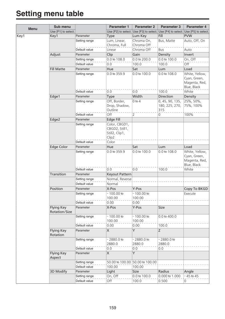
159
MenuSub menu Parameter 1 Parameter 2 Parameter 3 Parameter 4
Use [F1] to select. Use [F2] to select. Use [F3] to select. Use [F4] to select. Use [F5] to select.Key1 Key1 Parameter Type Lum Key Fill PVW
Setting range Lum, Linear, Chroma, Full
Chroma On, Chroma Off
Bus, Matte Auto, Off, On
Default value Linear Chroma Off Bus Auto
Adjust Parameter Clip Gain Density Invert
Setting range 0.0 to 108.0 0.0 to 200.0 0.0 to 100.0 On, Off
Default value 0.0 100.0 100.0 Off
Fill Matte Parameter Hue Sat Lum Load
Setting range 0.0 to 359.9 0.0 to 100.0 0.0 to 108.0 White, Yellow, Cyan, Green, Magenta, Red, Blue, Black
Default value 0.0 0.0 100.0 White
Edge1 Parameter Type Width Direction Density
Setting range Off, Border, Drop, Shadow, Outline
0 to 4 0, 45, 90, 135, 180, 225, 270, 315
25%, 50%, 75%, 100%
Default value Off 2 0 100%
Edge2 Parameter Edge Fill
Setting range Color, CBGD1, CBGD2, Still1, Still2, Clip1, Clip2
Default value Color
Edge Color Parameter Hue Sat Lum Load
Setting range 0.0 to 359.9 0.0 to 100.0 0.0 to 108.0 White, Yellow, Cyan, Green, Magenta, Red, Blue, Black
Default value 0.0 0.0 100.0 White
Transition Parameter Keyout Pattern
Setting range Normal, Reverse
Default value Normal
Position Parameter X-Pos Y-Pos Copy To BKGD
Setting range � 100.00 to 100.00
� 100.00 to 100.00
Execute
Default value 0.00 0.00
Flying Key Rotation/Size
Parameter X-Pos Y-Pos Size
Setting range � 100.00 to 100.00
� 100.00 to 100.00
0.0 to 400.0
Default value 0.00 0.00 100.0
Flying Key Rotation
Parameter X Y Z
Setting range � 2880.0 to 2880.0
� 2880.0 to 2880.0
� 2880.0 to 2880.0
Default value 0.0 0.0 0.0
Flying Key Aspect
Parameter X Y
Setting range 50.00 to 100.00 50.00 to 100.00
Default value 100.00 100.00
3D Modify Parameter Light Size Radius Angle
Setting range On, Off 0.0 to 100.0 0.000 to 1.000 � 45 to 45
Default value Off 100.0 0.500 0
Setting menu table

160
MenuSub menu Parameter 1 Parameter 2 Parameter 3 Parameter 4
Use [F1] to select. Use [F2] to select. Use [F3] to select. Use [F4] to select. Use [F5] to select.Key1 Mask Parameter Mask Invert
Setting range Off, Manual, 4:3
On, Off
Default value Off Off
Mask Adjust Parameter Left Top Bottom Right
Setting range � 50.00 to 50.00 � 50.00 to 50.00 � 50.00 to 50.00 � 50.00 to 50.00
Default value � 25.00 25.00 � 25.00 25.00
PinP Parameter PinP Full Key Shape Density
Setting range On, Off On, Off Square, Circle, Heart, Flower, Star
0.0 to 100.0
Default value Off On Square 100.0
PinP Border Parameter Border Width Soft Mode
Setting range On, Off 0.1 to 100.0 0.0 to 100.0 Fix, Variable
Default value Off 5.0 0.0 Fix
PinP Position Parameter X-Pos Y-Pos Size
Setting range � 100.00 to 100.00
� 100.00 to 100.00
0.0 to 100.0
Default value 0.00 0.00 25.0
PinP Trim Parameter Trim Pair Preset
Setting range Off, On(Disabled when set to anything other than Square)
On, Off 16:9, 12:9, 9:9, 7:9, 6:9, Manual
Default value Off Off 16:9
PinP Trim Adjust
Parameter Left Top Bottom Right
Setting range � 50.00 to 50.00 � 50.00 to 50.00 � 50.00 to 50.00 � 50.00 to 50.00
Default value � 50.00 50.00 � 50.00 50.00
PinP Sync Parameter Symmetry Copy To DSK1
Setting range Off, X, Y, Center, Same
Execute
Default value Off
Key Signal Coupling
Parameter Independent
Setting range On, Off
Default value Off
Key Priority Parameter Key1 Key2 Key3
Setting range 1st, 2nd, 3rd 1st, 2nd, 3rd 1st, 2nd, 3rd
Default value 3rd 2nd 1st
Key On Parameter Key1
Setting range On, Off
Default value Off
Setting menu table

161
MenuSub menu Parameter 1 Parameter 2 Parameter 3 Parameter 4
Use [F1] to select. Use [F2] to select. Use [F3] to select. Use [F4] to select. Use [F5] to select.Key2 Key1 Parameter Type Lum Key Fill PVW
Setting range Lum, Linear, Full Chroma On, Chroma Off
Bus, Matte Off, On
Default value Linear Chroma Off Bus Off
Adjust Parameter Clip Gain Density Invert
Setting range 0.0 to 108.0 0.0 to 200.0 0.0 to 100.0 On, Off
Default value 0.0 100.0 100.0 Off
Fill Matte Parameter Hue Sat Lum Load
Setting range 0.0 to 359.9 0.0 to 100.0 0.0 to 108.0 White, Yellow, Cyan, Green, Magenta, Red, Blue, Black
Default value 0.0 0.0 100.0 White
Edge1 Parameter Type Width Direction Density
Setting range Off, Border, Drop, Shadow, Outline
0 to 4 0, 45, 90, 135, 180, 225, 270, 315
25%, 50%, 75%, 100%
Default value Off 2 0 100%
Edge2 Parameter Edge Fill
Setting range Color, CBGD1, CBGD2, Still1, Still2, Clip1, Clip2
Default value Color
Edge Color Parameter Hue Sat Lum Load
Setting range 0.0 to 359.9 0.0 to 100.0 0.0 to 108.0 White, Yellow, Cyan, Green, Magenta, Red, Blue, Black
Default value 0.0 0.0 100.0 White
Mask Parameter Mask Invert
Setting range Off, Manual, 4:3
On, Off
Default value Off Off
Mask Adjust Parameter Left Top Bottom Right
Setting range � 50.00 to 50.00 � 50.00 to 50.00 � 50.00 to 50.00 � 50.00 to 50.00
Default value � 25.00 25.00 � 25.00 25.00
PinP Parameter PinP Full Key Shape Density
Setting range On, Off On, Off Square, Circle, Heart, Flower, Star
0.0 to 100.0
Default value Off On Square 100.0
PinP Border Parameter Border Width Soft Mode
Setting range Off, On 0.1 to 100.0 0.0 to 100.0 Fix, Variable
Default value Off 5.0 0.0 Fix
PinP Position Parameter X-Pos Y-Pos Size
Setting range � 100.00 to 100.00
� 100.00 to 100.00
0.00 to 100.00
Default value 0.00 0.00 25.00
Setting menu table

162
MenuSub menu Parameter 1 Parameter 2 Parameter 3 Parameter 4
Use [F1] to select. Use [F2] to select. Use [F3] to select. Use [F4] to select. Use [F5] to select.Key2 PinP Trim Parameter Trim Pair Preset
Setting range Off, On(Disabled when set to anything other than Square)
Off, On 16:9, 12:9, 9:9, 7:9, 6:9, Manual
Default value Off Off 16:9
PinP Trim Adjust
Parameter Left Top Bottom Right
Setting range � 50.00 to 50.00 � 50.00 to 50.00 � 50.00 to 50.00 � 50.00 to 50.00
Default value � 40.00 40.00 � 40.00 40.00
PinP Sync Parameter Symmetry Copy To DSK1
Setting range Off, X, Y, Center, Same
Execute
Default value Off
Key Signal Coupling
Parameter Independent
Setting range On, Off
Default value Off
Key Priority Parameter Key1 Key2 Key3
Setting range 1st, 2nd, 3rd 1st, 2nd, 3rd 1st, 2nd, 3rd
Default value 3rd 2nd 1st
Key On Parameter Key2
Setting range On, Off
Default value Off
Key3 Key1 Parameter Type Lum Key Fill PVW
Setting range Lum, Linear, Full Chroma On, Chroma Off
Bus, Matte Off, On
Default value Linear Chroma Off Bus Off
Adjust Parameter Clip Gain Density Invert
Setting range 0.0 to 108.0 0.0 to 200.0 0.0 to 100.0 On, Off
Default value 0.0 100.0 100.0 Off
Fill Matte Parameter Hue Sat Lum Load
Setting range 0.0 to 359.9 0.0 to 100.0 0.0 to 108.0 White, Yellow, Cyan, Green, Magenta, Red, Blue, Black
Default value 0.0 0.0 100.0 White
Mask Parameter Mask Invert
Setting range Off, Manual, 4:3
On, Off
Default value Off Off
Mask Adjust Parameter Left Top Bottom Right
Setting range � 50.00 to 50.00 � 50.00 to 50.00 � 50.00 to 50.00 � 50.00 to 50.00
Default value � 25.00 25.00 � 25.00 25.00
Key Signal Coupling
Parameter Independent
Setting range On, Off
Default value Off
Key Priority Parameter Key1 Key2 Key3
Setting range 1st, 2nd, 3rd 1st, 2nd, 3rd 1st, 2nd, 3rd
Default value 3rd 2nd 1st
Key On Parameter Key2
Setting range On, Off
Default value Off
Setting menu table

163
MenuSub menu Parameter 1 Parameter 2 Parameter 3 Parameter 4
Use [F1] to select. Use [F2] to select. Use [F3] to select. Use [F4] to select. Use [F5] to select.Chroma Key Chroma Key Parameter Select Key Type
Setting range Key1, DSK1 Linked to the Key Type of Key1 or DSK selected in Select
Default value Key1
Auto Compute Parameter Auto Compute Reset
Setting range Execute Execute
Default value
Adjust Parameter Narrow Phase
Setting range Off, 0.5, 1.0, 1.5
� 4.0 to 4.0
Default value Off 0.0
Sampling Parameter Chroma PVW Mode Sampling Undo
Setting range Off, Key1, DSK1 Select BG, Clean BG, Clean FG, Sponge, Fine Tuning
Execute Execute
Default value Off Select BG Color
Sampling Area Parameter X-Pos Y-Pos Size
Setting range � 50.00 to 50.00 � 50.00 to 50.00 0.1 to 100.0
Default value 0.00 0.00 10.0
Fine Tuning Parameter Spill Trans Detail
Setting range � 1000 to 1000 � 1000 to 1000 � 1000 to 1000
Default value 0 0 0
DSK1 DSK1 Parameter Type Lum Key Fill PVW
Setting range Lum, Linear, Chroma, Full
Chroma On, Chroma Off
Bus, Matte Off, On
Default value Linear Chroma Off Bus Off
Adjust Parameter Clip Gain Density Invert
Setting range 0.0 to 108.0 0.0 to 200.0 0.0 to 100.0 On, Off
Default value 0.0 100.0 100.0 Off
Fill Matte Parameter Hue Sat Lum Load
Setting range 0.0 to 359.9 0.0 to 100.0 0.0 to 108.0 White, Yellow, Cyan, Green, Magenta, Red, Blue, Black
Default value 0.0 0.0 100.0 White
Setting menu table
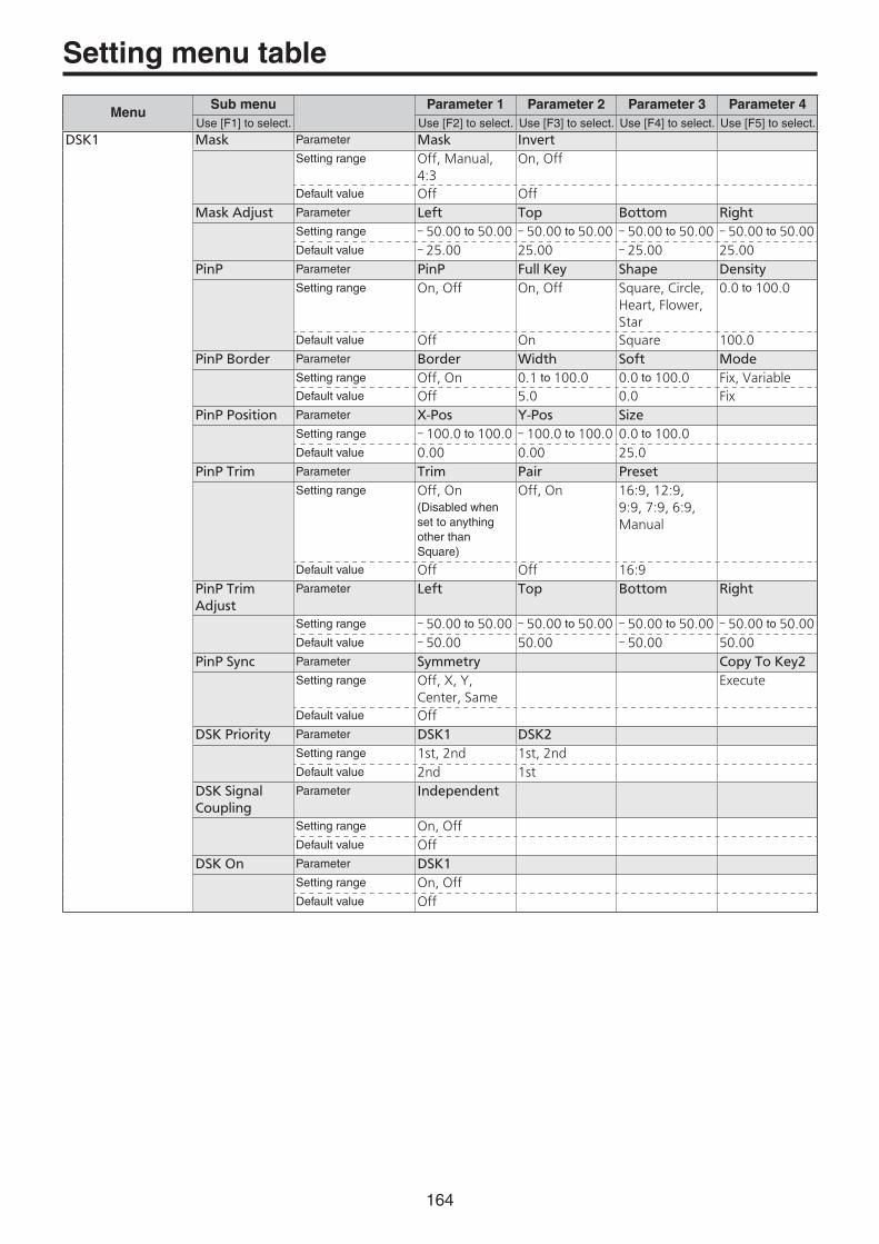
164
MenuSub menu Parameter 1 Parameter 2 Parameter 3 Parameter 4
Use [F1] to select. Use [F2] to select. Use [F3] to select. Use [F4] to select. Use [F5] to select.DSK1 Mask Parameter Mask Invert
Setting range Off, Manual, 4:3
On, Off
Default value Off Off
Mask Adjust Parameter Left Top Bottom Right
Setting range � 50.00 to 50.00 � 50.00 to 50.00 � 50.00 to 50.00 � 50.00 to 50.00
Default value � 25.00 25.00 � 25.00 25.00
PinP Parameter PinP Full Key Shape Density
Setting range On, Off On, Off Square, Circle, Heart, Flower, Star
0.0 to 100.0
Default value Off On Square 100.0
PinP Border Parameter Border Width Soft Mode
Setting range Off, On 0.1 to 100.0 0.0 to 100.0 Fix, Variable
Default value Off 5.0 0.0 Fix
PinP Position Parameter X-Pos Y-Pos Size
Setting range � 100.0 to 100.0 � 100.0 to 100.0 0.0 to 100.0
Default value 0.00 0.00 25.0
PinP Trim Parameter Trim Pair Preset
Setting range Off, On(Disabled when set to anything other than Square)
Off, On 16:9, 12:9, 9:9, 7:9, 6:9, Manual
Default value Off Off 16:9
PinP Trim Adjust
Parameter Left Top Bottom Right
Setting range � 50.00 to 50.00 � 50.00 to 50.00 � 50.00 to 50.00 � 50.00 to 50.00
Default value � 50.00 50.00 � 50.00 50.00
PinP Sync Parameter Symmetry Copy To Key2
Setting range Off, X, Y, Center, Same
Execute
Default value Off
DSK Priority Parameter DSK1 DSK2
Setting range 1st, 2nd 1st, 2nd
Default value 2nd 1st
DSK Signal Coupling
Parameter Independent
Setting range On, Off
Default value Off
DSK On Parameter DSK1
Setting range On, Off
Default value Off
Setting menu table

165
MenuSub menu Parameter 1 Parameter 2 Parameter 3 Parameter 4
Use [F1] to select. Use [F2] to select. Use [F3] to select. Use [F4] to select. Use [F5] to select.DSK2 DSK1 Parameter Type Lum Key Fill PVW
Setting range Lum, Linear, Full Chroma On, Chroma Off
Bus, Matte Off, On
Default value Linear Chroma Off Bus Off
Adjust Parameter Clip Gain Density Invert
Setting range 0.0 to 108.0 0.0 to 200.0 0.0 to 100.0 On, Off
Default value 0.0 100.0 100.0 Off
Fill Matte Parameter Hue Sat Lum Load
Setting range 0.0 to 359.9 0.0 to 100.0 0.0 to 108.0 White, Yellow, Cyan, Green, Magenta, Red, Blue, Black
Default value 0.0 0.0 100.0 White
Mask Parameter Mask Invert
Setting range Off, Manual, 4:3
On, Off
Default value Off Off
Mask Adjust Parameter Left Top Bottom Right
Setting range � 50.00 to 50.00 � 50.00 to 50.00 � 50.00 to 50.00 � 50.00 to 50.00
Default value � 25.00 25.00 � 25.00 25.00
DSK Priority Parameter DSK1 DSK2
Setting range 1st, 2nd 1st, 2nd
Default value 2nd 1st
DSK Signal Coupling
Parameter Independent
Setting range On, Off
Default value Off
DSK On Parameter DSK2
Setting range On, Off
Default value Off
Setting menu table

166
MenuSub menu Parameter 1 Parameter 2 Parameter 3 Parameter 4
Use [F1] to select. Use [F2] to select. Use [F3] to select. Use [F4] to select. Use [F5] to select.Time BKGD Parameter TransTime Time WaitTime Wait
Setting range 1s00f to 0s00f 1s00f to 0s00f Off, On
Default value 1s00f 1s00f Off
Key1 Parameter TransTime Time
Setting range 0 to 999 (Frame)
Default value 1s00f
Key2 Parameter TransTime Time
Setting range 0 to 999 (Frame)
Default value 1s00f
Key3 Parameter TransTime Time
Setting range 0 to 999 (Frame)
Default value 1s00f
DSK1 Parameter TransTime Time
Setting range 0 to 999 (Frame)
Default value 1s00f
DSK2 Parameter TransTime Time
Setting range 0 to 999 (Frame)
Default value 1s00f
AUX1 BUS Trans
Parameter TransTime Time Transition
Setting range 0 to 999 (Frame)
On, Off
Default value 1s00f Off
AUX2 BUS Trans
Parameter TransTime Time Transition
Setting range 0 to 999 (Frame)
On, Off
Default value 1s00f Off
Effect Dissolve Parameter TransTime Time
Setting range 0 to 999 (Frame)
Default value 1s00f
FTB Parameter TransTime Time
Setting range 0 to 999 (Frame)
Default value 1s00f
Setting menu table
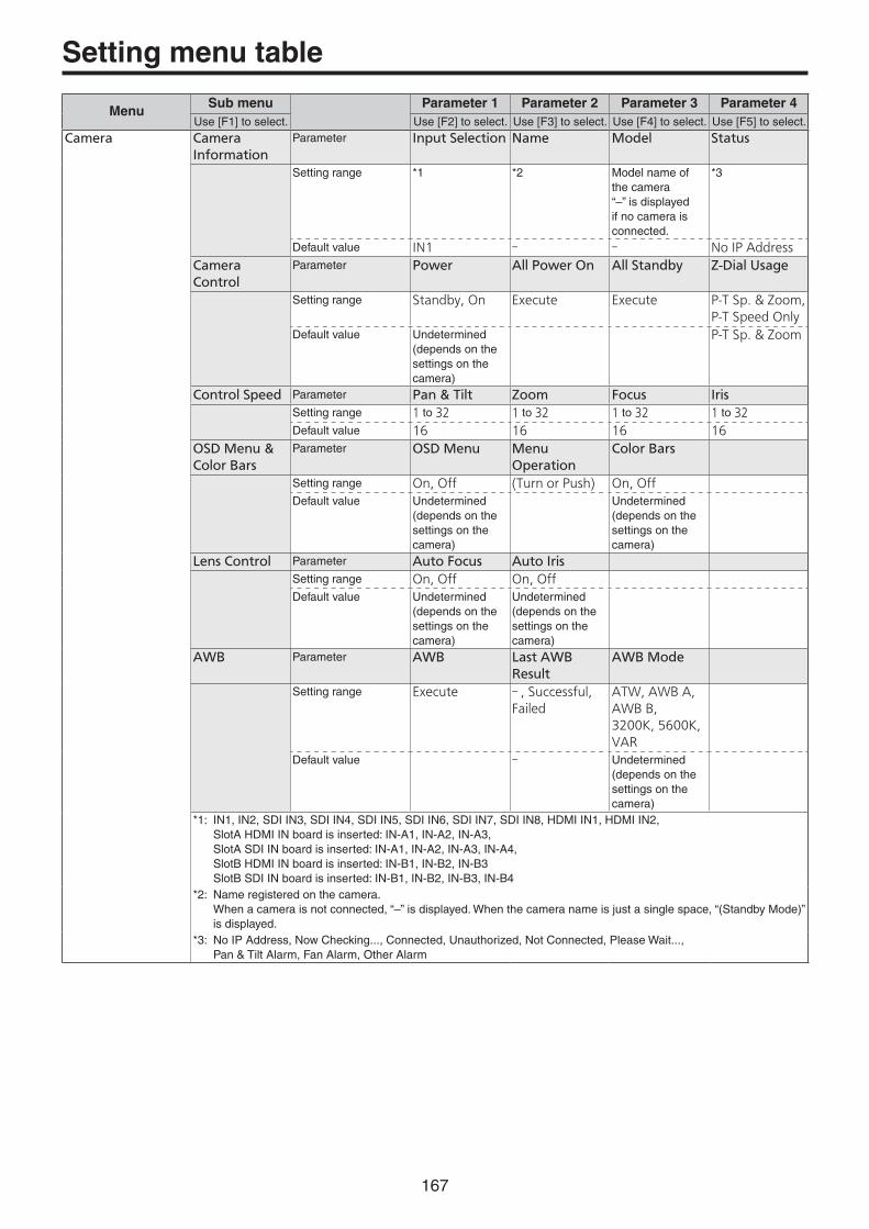
167
MenuSub menu Parameter 1 Parameter 2 Parameter 3 Parameter 4
Use [F1] to select. Use [F2] to select. Use [F3] to select. Use [F4] to select. Use [F5] to select.Camera Camera
InformationParameter Input Selection Name Model Status
Setting range *1 *2 Model name of the camera“–” is displayed if no camera is connected.
*3
Default value IN1 � � No IP Address
Camera Control
Parameter Power All Power On All Standby Z-Dial Usage
Setting range Standby, On Execute Execute P-T Sp. & Zoom,P-T Speed Only
Default value Undetermined (depends on the settings on the camera)
P-T Sp. & Zoom
Control Speed Parameter Pan & Tilt Zoom Focus Iris
Setting range 1 to 32 1 to 32 1 to 32 1 to 32
Default value 16 16 16 16
OSD Menu & Color Bars
Parameter OSD Menu Menu Operation
Color Bars
Setting range On, Off (Turn or Push) On, Off
Default value Undetermined (depends on the settings on the camera)
Undetermined (depends on the settings on the camera)
Lens Control Parameter Auto Focus Auto Iris
Setting range On, Off On, Off
Default value Undetermined (depends on the settings on the camera)
Undetermined (depends on the settings on the camera)
AWB Parameter AWB Last AWB Result
AWB Mode
Setting range Execute � , Successful, Failed
ATW, AWB A, AWB B,3200K, 5600K, VAR
Default value � Undetermined (depends on the settings on the camera)
*1: IN1, IN2, SDI IN3, SDI IN4, SDI IN5, SDI IN6, SDI IN7, SDI IN8, HDMI IN1, HDMI IN2, SlotA HDMI IN board is inserted: IN-A1, IN-A2, IN-A3, SlotA SDI IN board is inserted: IN-A1, IN-A2, IN-A3, IN-A4, SlotB HDMI IN board is inserted: IN-B1, IN-B2, IN-B3 SlotB SDI IN board is inserted: IN-B1, IN-B2, IN-B3, IN-B4
*2: Name registered on the camera. When a camera is not connected, “–” is displayed. When the camera name is just a single space, “(Standby Mode)” is displayed.
*3: No IP Address, Now Checking..., Connected, Unauthorized, Not Connected, Please Wait..., Pan & Tilt Alarm, Fan Alarm, Other Alarm
Setting menu table

168
MenuSub menu Parameter 1 Parameter 2 Parameter 3 Parameter 4
Use [F1] to select. Use [F2] to select. Use [F3] to select. Use [F4] to select. Use [F5] to select.Camera ABB Parameter ABB Last ABB
Result
Setting range Execute � , Successful, Failed
Default value �
Gain1 Parameter Gain R Gain B Gain
Setting range *1 *2
Default value Undetermined (depends on the settings on the camera)
Undetermined (depends on the settings on the camera)
Undetermined (depends on the settings on the camera)
Gain2 Parameter AGC Max Gain Super Gain
Setting range *3 ON, OFF
Default value Undetermined (depends on the settings on the camera)
Undetermined (depends on the settings on the camera)
Pedestal Parameter M Ped. R Ped. G Ped. B Ped.
Setting range *4 � 100 to 100 � 100 to 100 � 100 to 100
Default value Undetermined (depends on the settings on the camera)
Undetermined (depends on the settings on the camera)
Undetermined (depends on the settings on the camera)
Undetermined (depends on the settings on the camera)
Preset Settings Parameter Preset Scope Speed Preset Sp. Unit Preset Sp.Table
Setting range Mode A, Mode B, Mode C
*5 Speed Table, Time
Slow, Fast
Default value Undetermined (depends on the settings on the camera)
Undetermined (depends on the settings on the camera)
Undetermined (depends on the settings on the camera)
Undetermined (depends on the settings on the camera)
Lock Parameter Pan & Tilt Lock Zoom Lock Focus Lock Iris Lock
Setting range On, Off On, Off On, Off On, Off
Default value Off Off Off Off
*1: AW-UE150/AW-HR140: 0 to 42 dB, AGC (Super Gain: ON), 0 to 36 dB, AGC (Super Gain: OFF) AW-HE130/AW-HN130: 0 to 36 dB, AGC AW-UE70/AW-UN70/AW-HE40/AW-HN40/AW-HE42: 0, 3, …, 48 dB (3 dB increments), AGC
*2: AW-UE150: �200 to 200 AW-HR140/AW-HE130/AW-HN130: �150 to 150 AW-UE70/AW-UN70/AW-HE40/AW-HN40/AW-HE42: �30 to 30
*3: AW-UE150: �200 to 200 AW-HR140/AW-HE130/AW-HN130: �150 to 150 AW-UE70/AW-UN70/AW-HE40/AW-HN40/AW-HE42: �10 to 10
*4: AW-UE150/AW-HR140/AW-HE130/AW-HN130: 6 dB, 12 dB, 18 dB AW-UE70/AW-UN70/AW-HE40/AW-HN40/AW-HE42: 6 dB, 12 dB, 18 dB, 24 dB, 30 dB, 36 dB, 42 dB, 48 dB
*5: AW-UE150: 1 to 30 (Preset Sp.Unit: Speed Table) 1 to 99 (Preset Sp.Unit: Time) Other than AW-UE150: 1 to 30
Project File Last Load File Parameter Media File Name
Setting range
Default value Display only Display only
Last Load Date Parameter Date
Setting range
Default value Display only
Project File Parameter Load Save Delete Rename
Setting range Execute Execute Execute Execute
Default value
Target Select1 Parameter Setup Shot Event Macro
Setting range On, Off On, Off On, Off On, Off
Default value On On On On
Target Select2 Parameter Still Clip
Setting range On, Off On, Off
Default value Off Off
Setting menu table

169
MenuSub menu Parameter 1 Parameter 2 Parameter 3 Parameter 4
Use [F1] to select. Use [F2] to select. Use [F3] to select. Use [F4] to select. Use [F5] to select.SD Card Card
ManagementParameter Mount Umount Format
Setting range Execute Execute Execute
Default value
Mode Parameter Load Delete Rename Sort
Setting range Execute Execute Execute Newest, Oldest, Name
Default value Name
File Parameter Save Save Type Format
Setting range Execute Still1, Still2, Clip1, Clip2, Project, Log
bmp, tga, png, jpeg, tif, gif
Default value Project png
Target Select1 Parameter Setup Shot Event Macro
Setting range On, Off On, Off On, Off On, Off
Default value On On On On
Target Select2 Parameter Still Clip
Setting range On, Off On, Off
Default value Off Off
Create Thumbnail
Parameter Still Clip
Setting range Execute Execute
Default value
Card Information
Parameter Free Total
Setting range
Default value
Setting menu table

170
MenuSub menu Parameter 1 Parameter 2 Parameter 3 Parameter 4
Use [F1] to select. Use [F2] to select. Use [F3] to select. Use [F4] to select. Use [F5] to select.Video Memory
When Still1, Sitll2
Video Memory1
Parameter Select Rec Key
Setting range Still1, Still2,Clip1, Clip2
Execute On, Off
Default value Still1
Rec1 Parameter VMEM Video VMEM Key
Setting range AUX1 to 4 AUX1 to 4
Default value AUX1 AUX1
Rec2 Parameter Preview Key Enable Review
Setting range On, Off On, Off On, Off
Default value Off On On
Memory Parameter Mode Select Save
Setting range Auto, Manual Still1, Still2, Clip1, Clip2, All
Execute
Default value Auto All
Video Memory
When Clip1, Clip2
Video Memory1
Parameter Select Rec Play Stop
Setting range Still1, Still2,Clip1, Clip2
Execute Execute Execute
Default value Still1
Video Memory2
Parameter LEAD LAST
Setting range Execute Execute
Default value
Video Memory3
Parameter Total Time Current Time Key Rec Lock
Setting range The setting range differs with each format.
On, Off On, Off
Default value On
Rec1 Parameter VMEM Video VMEM Key
Setting range AUX1 to 4 AUX1 to 4
Default value AUX1 AUX1
Rec2 Parameter Preview Key Enable Review
Setting range On, Off On, Off On, Off
Default value Off On On
Rec3 Parameter Loop Quality Audio
Setting range On, Off High, Standard On, Off
Default value Off Standard On
Limit Time Parameter Mode
Setting range 1f to 2m00s00f(when 59.94i)
Default value 5s00f
Play Mode1 Parameter Mode Reverse Variable Freeze
Setting range Lead, Last, Loop On, Off x1, x2, x4, x8, x1/2, x1/4, x1/8
Frame, Field
Default value Last Off x1 Frame
Play Mode2 Parameter Trans Sync Audio
Setting range Off, Auto, KEY1 ON, KEY2 ON, KEY3 ON, DSK1 ON, DSK2 ON,FTB ON, Fader
On, Off
Default value Off On
Memory Parameter Mode Select Save
Setting range Auto, Manual Still1, Still2, Clip1, Clip2, All
Execute
Default value Auto All
Setting menu table

171
MenuSub menu Parameter 1 Parameter 2 Parameter 3 Parameter 4
Use [F1] to select. Use [F2] to select. Use [F3] to select. Use [F4] to select. Use [F5] to select.Macro Store Select1 Parameter ME DSK AUX
Setting range On, Off On, Off On, Off
Default value On On On
Store Select2 Parameter MENU XPT OTHER
Setting range On, Off On, Off On, Off
Default value On On On
Insert Delay Parameter Time Set
Setting range 0 to 600 (Frame) Execute
Default value 1s00f
Macro Assign 1/6
Parameter XPT1 XPT2 XPT3 XPT4
Setting range Macro001 to Macro100, PlayCancel, No Assign
Macro001 to Macro100, PlayCancel, No Assign
Macro001 to Macro100, PlayCancel, No Assign
Macro001 to Macro100, PlayCancel, No Assign
Default value No Assign No Assign No Assign No Assign
Macro Assign 2/6
Parameter XPT5 XPT6 XPT7 XPT8
Setting range Macro001 to Macro100, PlayCancel, No Assign
Macro001 to Macro100, PlayCancel, No Assign
Macro001 to Macro100, PlayCancel, No Assign
Macro001 to Macro100, PlayCancel, No Assign
Default value No Assign No Assign No Assign No Assign
Macro Assign 3/6
Parameter XPT9 XPT10 XPT11 XPT12
Setting range Macro001 to Macro100, PlayCancel, No Assign
Macro001 to Macro100, PlayCancel, No Assign
Macro001 to Macro100, PlayCancel, No Assign
Macro001 to Macro100, PlayCancel, No Assign
Default value No Assign No Assign No Assign No Assign
Macro Assign 4/6
Parameter XPT13 XPT14 XPT15 XPT16
Setting range Macro001 to Macro100, PlayCancel, No Assign
Macro001 to Macro100, PlayCancel, No Assign
Macro001 to Macro100, PlayCancel, No Assign
Macro001 to Macro100, PlayCancel, No Assign
Default value No Assign No Assign No Assign No Assign
Macro Assign 5/6
Parameter XPT17 XPT18 XPT19 XPT20
Setting range Macro001 to Macro100, PlayCancel, No Assign
Macro001 to Macro100, PlayCancel, No Assign
Macro001 to Macro100, PlayCancel, No Assign
Macro001 to Macro100, PlayCancel, No Assign
Default value No Assign No Assign No Assign No Assign
Macro Assign 6/6
Parameter XPT21 XPT22 XPT23 XPT24
Setting range Macro001 to Macro100, PlayCancel, No Assign
Macro001 to Macro100, PlayCancel, No Assign
Macro001 to Macro100, PlayCancel, No Assign
Macro001 to Macro100, PlayCancel, No Assign
Default value No Assign No Assign No Assign No Assign
Attach Parameter Enable Attach Setting
Setting range Off, On Execute
Default value Off
Setting menu table

172
MenuSub menu Parameter 1 Parameter 2 Parameter 3 Parameter 4
Use [F1] to select. Use [F2] to select. Use [F3] to select. Use [F4] to select. Use [F5] to select.Shot Memory Target Select1 Parameter ME DSK AUX
Setting range On, Off On, Off On, Off
Default value On On On
Target Select2 Parameter CBGD
Setting range On, Off
Default value On
Register Parameter Page No. Rename()Setting range 1 to 10 1 to 10 Execute
Default value 1 1
Path Parameter Effect PinP Bus Hue Path
Setting range Cut, Dissolve Cut, Dissolve Short, Long, CW, CCW
Default value Dissolve Dissolve Short
Event Memory Mark Parameter PAUSE CLIP GPI-Out
Setting range On, Off Off, Clip1, Clip2 Off, EMEM-01 to EMEM-20
Default value Off Off Off
Event Duration Parameter (Time) Set
Setting range 0 to 215999 (Frame)
Execute
Default value 1s00f
Total Duration Parameter (Time) Set
Setting range 0 to 215999 (Frame)
Execute
Default value 1s00f
Timeline Parameter View
Setting range Normal, Wide
Default value Wide
Play Parameter Loop Play Mode
Setting range Once, Loop Normal, Reverse
Default value Once Normal
Target Select1 Parameter ME DSK AUX
Setting range On, Off On, Off On, Off
Default value On On On
Target Select2 Parameter CBGD CLIP
Setting range On, Off On, Off
Default value On On
Register Parameter Page No. Rename() Copy To
Setting range 1 to 10 1 to 10 Execute 1 to 100
Default value 1 1 1
Path Parameter Trans Path Hue Path
Setting range Linear, Spline, Step
Short, Long, CW, CCW, Step
Default value Linear CW
Setting menu table

173
MenuSub menu Parameter 1 Parameter 2 Parameter 3 Parameter 4
Use [F1] to select. Use [F2] to select. Use [F3] to select. Use [F4] to select. Use [F5] to select.XPT XPT Assign 1/6 Parameter XPT1 Signal XPT2 Signal XPT3 Signal XPT4 Signal
Setting range IN1, IN2, SDI IN3 to 8, IN-A1, IN-A2, IN-A3, IN-A4, IN-B1, IN-B2, IN-B3, IN-B4, Black, CBGD 1, CBGD 2, CBAR, Still 1V, Still 1K, Still 2V, Still 2K, Clip 1V, Clip 1K, Clip 2V, Clip 2K, CLN, ME PGM, Key Out, None
Default value IN1 IN2 SDI IN3 SDI IN4
XPT Assign 2/6 Parameter XPT5 Signal XPT6 Signal XPT7 Signal XPT8 Signal
Setting range The setting range is the same as for the XPT Assign 1/6 sub menu.Default value SDI IN5 SDI IN6 SDI IN7 SDI IN8
XPT Assign 3/6 Parameter XPT9 Signal XPT10 Signal XPT11 Signal XPT12 Signal
Setting range The setting range is the same as for the XPT Assign 1/6 sub menu.Default value CBAR CBGD 1 CBGD 2 None
XPT Assign 4/6 Parameter XPT13 Signal XPT14 Signal XPT15 Signal XPT16 Signal
Setting range The setting range is the same as for the XPT Assign 1/6 sub menu.Default value None None None None
XPT Assign 5/6 Parameter XPT17 Signal XPT18 Signal XPT19 Signal XPT20 Signal
Setting range The setting range is the same as for the XPT Assign 1/6 sub menu.Default value None None None None
XPT Assign 6/6 Parameter XPT21 Signal XPT22 Signal XPT23 Signal XPT24 Signal
Setting range The setting range is the same as for the XPT Assign 1/6 sub menu.Default value None None None None
XPT Setting Parameter Shift Shift-Lock
Setting range Off, Right, Left On, Off
Default value Right Off
XPT Switch Parameter Timing
Setting range Any, Field1, Field2
Default value Any
Multi View Display Parameter Select
Setting range MV1, MV2
Default value MV1
Setting menu table

174
MenuSub menu Parameter 1 Parameter 2 Parameter 3 Parameter 4
Use [F1] to select. Use [F2] to select. Use [F3] to select. Use [F4] to select. Use [F5] to select.Multi View Display
When MV1
MV1 Split Parameter Split
Setting range 4Split, 5-aSplit, 5-bSplit, 6-aSplit, 6-bSplit, 9Split, 10-aSplit, 10-bSplit, 12Split, 16Split
Default value 10-aSplit
MV1 Pattern 1/4
Parameter Pos1 Signal Pos2 Signal Pos3 Signal Pos4 Signal
Setting range IN1, IN2, SDI IN3, SDI IN4, SDI IN5, SDI IN6, SDI IN7, SDI IN8, IN-A1, IN-A2, IN-A3, IN-A4, IN-B1, IN-B2, IN-B3, IN-B4, CBGD 1, CBGD 2, Still 1V, Still 1K, Still 2V, Still 2K, Clip 1V, Clip 1K, Clip 2V, Clip 2K, PGM, PVW, CLN, ME PGM, Key Out, MV1, MV2, AUX1, AUX2, AUX3, AUX4, Clock
Default value PGM PVW IN1 IN2
MV1 Pattern 2/4
Parameter Pos5 Signal Pos6 Signal Pos7 Signal Pos8 Signal
Setting range The setting range is the same as for the MV1 Pattern 1/4 sub menu.Default value SDI IN3 SDI IN4 SDI IN5 SDI IN6
MV1 Pattern 3/4
Parameter Pos9 Signal Pos10 Signal Pos11 Signal Pos12 Signal
Setting range The setting range is the same as for the MV1 Pattern 1/4 sub menu.Default value SDI IN7 SDI IN8 Still 1V Still 2V
MV1 Pattern 4/4
Parameter Pos13 Signal Pos14 Signal Pos15 Signal Pos16 Signal
Setting range The setting range is the same as for the MV1 Pattern 1/4 sub menu.Default value Clip 1V Clip 2V AUX1 AUX2
MV1 Frame Parameter Frame Character Label
Setting range LUM0%, LUM25%, LUM50%, LUM75%, LUM100%, Off
On, Off
Default value LUM75% On
MV1 Tally Group1
Parameter Box Label Left Label Right
Setting range On, Off On, Off On, Off
Default value Off Off Off
MV1 Tally Group2
Parameter Box Label Left Label Right
Setting range On, Off On, Off On, Off
Default value Off Off Off
Display Parameter Level Meter Input Status Marker Marker Size
Setting range On, Off On, Off 4:3, 16:9, Off 80 to 100%
Default value Off On Off 95%
Setting menu table

175
MenuSub menu Parameter 1 Parameter 2 Parameter 3 Parameter 4
Use [F1] to select. Use [F2] to select. Use [F3] to select. Use [F4] to select. Use [F5] to select.Multi View Display
When MV2
MV2 Split Parameter Split
Setting range 4Split, 5-aSplit, 5-bSplit, 6-aSplit, 6-bSplit, 9Split, 10-aSplit, 10-bSplit, 12Split, 16Split
Default value 10-aSplit
MV2 Pattern 1/4
Parameter Pos1 Signal Pos2 Signal Pos3 Signal Pos4 Signal
Setting range IN1, IN2, SDI IN3, SDI IN4, SDI IN5, SDI IN6, SDI IN7, SDI IN8, IN-A1, IN-A2, IN-A3, IN-A4, IN-B1, IN-B2, IN-B3, IN-B4, CBGD 1, CBGD 2, Still 1V, Still 1K, Still 2V, Still 2K, Clip 1V, Clip 1K, Clip 2V, Clip 2K, PGM, PVW, CLN, ME PGM, Key Out, MV1, MV2, AUX1, AUX2, AUX3, AUX4, Clock
Default value IN1 IN2 CBGD 1 CBGD 2
MV2 Pattern 2/4
Parameter Pos5 Signal Pos6 Signal Pos7 Signal Pos8 Signal
Setting range The setting range is the same as for the MV2 Pattern 1/4 sub menu.Default value CBAR Black Still 1K Still 2K
MV2 Pattern 3/4
Parameter Pos9 Signal Pos10 Signal Pos11 Signal Pos12 Signal
Setting range The setting range is the same as for the MV2 Pattern 1/4 sub menu.Default value Clip 1K Clip 2K CLN ME PGM
MV2 Pattern 4/4
Parameter Pos13 Signal Pos14 Signal Pos15 Signal Pos16 Signal
Setting range The setting range is the same as for the MV2 Pattern 1/4 sub menu.Default value Key Out AUX3 AUX4 Clock
MV2 Frame Parameter Frame Character Label
Setting range LUM0%, LUM25%, LUM50%, LUM75%, LUM100%, Off
On, Off
Default value LUM75% On
MV2 Tally Red Parameter Box Label Left Label Right
Setting range On, Off On, Off On, Off
Default value Off Off Off
MV2 Tally Green
Parameter Box Label Left Label Right
Setting range On, Off On, Off On, Off
Default value Off Off Off
Display Parameter Level Meter Input Status Marker Marker Size
Setting range On, Off On, Off 4:3, 16:9, Off 80 to 100%
Default value Off On Off 95%
Input Input Parameter Select Color Space SDI/HDMI
Setting range IN1, IN2, SDI IN3, SDI IN4, SDI IN5, SDI IN6, SDI IN7, SDI IN8,IN-A1, IN-A2, IN-A3, IN-A4, IN-B1, IN-B2, IN-B3, IN-B4
HDR BT.2020, HDR BT.709, SDR BT.709
SDI IN, HDMI IN
Default value IN1 SDR BT.709 SDI IN
Setting menu table

176
MenuSub menu Parameter 1 Parameter 2 Parameter 3 Parameter 4
Use [F1] to select. Use [F2] to select. Use [F3] to select. Use [F4] to select. Use [F5] to select.Input (SDI) / X(***)
p IN1, IN2, SDI IN3 to 8, IN-A1 to 4 or IN-B1 to 4 is displayed in the X part.p The material name
(up to 32 characters) is displayed in the *** part.
Status Parameter Format Audio Color Space
Setting range
Default value
FS Parameter Mode Delay
Setting range Off, Normal, Auto
0F to 8F
Default value Auto 0F
Freeze Parameter Select Freeze
Setting range Frame, Field On, Off
Default value Frame Off
Name Parameter Type Name
Setting range Default, User
Default value Default
Up/Down Converter
Parameter Move Detect Sharp
Setting range 1 to 5 1 to 5
Default value 3 3
C/C Operation Parameter C/C Limit
Setting range On, Off Off, 108, 104, 100
Default value Off Off
C/C Process Parameter Y-Gain Pedestal C-Gain Hue
Setting range 0.0 to 200.0 � 20.0 to 200.0 0.0 to 200.0 0.0 to 359.9
Default value 100.0 0.0 100.0 0.0
C/C Tone1 Black
Parameter Red Green Blue RGB Link
Setting range � 10.0 to 108.0 � 10.0 to 108.0 � 10.0 to 108.0 On, Off
Default value 0.0 0.0 0.0 Off
C/C Tone2 Gray L
Parameter Red Green Blue
Setting range � 10.0 to 108.0 � 10.0 to 108.0 � 10.0 to 108.0Default value 33.3 33.3 33.3
C/C Tone3 Gray H
Parameter Red Green Blue
Setting range � 10.0 to 108.0 � 10.0 to 108.0 � 10.0 to 108.0Default value 66.6 66.6 66.6
C/C Tone4 White
Parameter Red Green Blue
Setting range � 10.0 to 108.0 � 10.0 to 108.0 � 10.0 to 108.0Default value 100.0 100.0 100.0
C/C Matrix R/G Parameter R-G R-B G-R G-B
Setting range � 0.60 to 0.60 � 0.60 to 0.60 � 0.60 to 0.60 � 0.60 to 0.60
Default value 0.00 0.00 0.00 0.00
C/C Matrix B Parameter B-R B-G
Setting range � 0.60 to 0.60 � 0.60 to 0.60
Default value 0.00 0.00
C/C Setting Parameter Init Target Initialize Copy Target Copy From
Setting range Process, Tone, RGB Matrix, All
Execute SDI IN5, SDI IN6, SDI IN7, SDI IN8, IN-A1, IN-A2, IN-A3, IN-A4, IN-B1, IN-B2, IN-B3, IN-B4
Execute
Default value All � SDI IN5 �
Setting menu table

177
MenuSub menu Parameter 1 Parameter 2 Parameter 3 Parameter 4
Use [F1] to select. Use [F2] to select. Use [F3] to select. Use [F4] to select. Use [F5] to select.Input (HDMI) / X(***)
p IN1, IN2, IN-A1 to 4 or IN-B1 to 4 is displayed in the X part.p The material name
(up to 10 characters) is displayed in the *** part.
Freeze Parameter Select Freeze
Setting range Frame, Field On, Off
Default value Frame Off
Limited Parameter Limited
Setting range On, Off
Default value Off
Name Parameter Type Name
Setting range Default, User
Default value Default
HDMI Input Parameter Scale
Setting range Fit-V, Fit-H, Full
Default value Full
HDMI Status Parameter Size Dot Clock H-Frequency V-Frequency
Setting range �
Default value ****x**** ***.*MHz **.*kHz **.*Hz
C/C Operation Parameter C/C Limit
Setting range On, Off Off, 108, 104, 100
Default value Off Off
C/C Process Parameter Y-Gain Pedestal C-Gain Hue
Setting range 0.0 to 200.0 � 20.0 to 200.0 0.0 to 200.0 0.0 to 359.9Default value 100.0 0.0 100.0 0.0
C/C Tone1 Black
Parameter Red Green Blue RGB Link
Setting range � 10.0 to 108.0 � 10.0 to 108.0 � 10.0 to 108.0 On, Off
Default value 0.0 0.0 0.0 Off
C/C Tone2 Gray L
Parameter Red Green Blue
Setting range � 10.0 to 108.0 � 10.0 to 108.0 � 10.0 to 108.0Default value 33.3 33.3 33.3
C/C Tone3 Gray H
Parameter Red Green Blue
Setting range � 10.0 to 108.0 � 10.0 to 108.0 � 10.0 to 108.0Default value 66.6 66.6 66.6
C/C Tone4 White
Parameter Red Green Blue
Setting range � 10.0 to 108.0 � 10.0 to 108.0 � 10.0 to 108.0Default value 100.0 100.0 100.0
C/C Matrix R/G Parameter R-G R-B G-R G-B
Setting range � 0.60 to 0.60 � 0.60 to 0.60 � 0.60 to 0.60 � 0.60 to 0.60Default value 0.00 0.00 0.00 0.00
C/C Matrix B Parameter B-R B-G
Setting range � 0.60 to 0.60 � 0.60 to 0.60Default value 0.00 0.00
C/C Setting Parameter Init Target Initialize Copy Target Copy From
Setting range Process, Tone, RGB Matrix, All
Execute IN-A1, IN-A2, IN-A3, IN-B1, IN-B2, IN-B3
Execute
Default value All � � �
Setting menu table

178
MenuSub menu Parameter 1 Parameter 2 Parameter 3 Parameter 4
Use [F1] to select. Use [F2] to select. Use [F3] to select. Use [F4] to select. Use [F5] to select.Input Camera
Settings1Parameter IP Address Port Edit IP Address Scan IP
Address
Setting range Need Edit/ScanNow Scanning…Not DetectedSelect From List
1 to 65535 Execute Execute
Default value Need Edit/Scan 80 �
Camera Settings2
Parameter Edit User Name
Edit Password Name Network Status
Setting range Execute Execute Name registered on the camera
No IP Address,Now Checking...,Connected,Unauthorized,Not Connected
Default value � No IP Address
Camera Settings3
Parameter Pan Direction Tilt Direction Tally (Group1)
Setting range Normal, Reverse Normal, Reverse Disable, Enable
Default value Normal Normal Enable
Camera Settings4
Parameter Zoom Direction
Focus Direction Iris Direction
Setting range Normal, Reverse Normal, Reverse Normal, Reverse
Default value Normal Normal Normal
Output Output Parameter Select Mode Color Space
Setting range SDI OUT1, SDI OUT2 , SDI OUT3, SDI OUT4, SDI OUT5, HDMI OUT1, HDMI OUT2, OUT-A1, OUT-A2, OUT-A3, OUT-A4, OUT-B1, OUT-B2, OUT-B3, OUT-B4
Normal, 1080p, 1080i, 720p
HDR BT.2020, HDR BT.709, SDR BT.709
Default value SDI OUT1 Normal SDR BT.709
Output (SDI) / Y
p SDI OUT1 to SDI OUT5, OUT A1, OUT A2, OUT A3, OUT A4, OUT B1, OUT B2, OUT B3 or OUT B4 is displayed in the Y part.
(OUT A1, OUT A2, OUT A3, OUT A4, OUT B1, OUT B2, OUT B3 and OUT B4 take effect when the AV-UHS5M2 unit has been connected.)
Assign Parameter Source
Setting range PGM, PVW, CLN, ME PGM, AUX1, AUX2, AUX3, AUX4, MV1, MV2, Key Out
Default value PGM(OUT1), PVW(OUT2), AUX1(OUT3), AUX2(OUT4), AUX3(OUT5), AUX4(OUTA1), AUX1(OUTA2), AUX2(OUTA3), AUX3(OUTB1), AUX4(OUTB2), AUX1(OUTB3)
Normal
Down Converter
Parameter Delay Sharp
Setting range Minimum, 1F Fix
1 to 5
Default value Minimum 3
Setting menu table

179
MenuSub menu Parameter 1 Parameter 2 Parameter 3 Parameter 4
Use [F1] to select. Use [F2] to select. Use [F3] to select. Use [F4] to select. Use [F5] to select.Output (HDMI) / Y
p HDMI OUT1, HDMI OUT2, OUT A1, OUT A2, OUT A3, OUT A4, OUT B1, OUT B2, OUT B3 or OUT B4 is displayed in the Y part.
Assign Parameter Source
Setting range PGM, PVW, CLN, ME PGM, AUX1, AUX2, AUX3, AUX4, MV1, MV2, Key Out
Default value MV1(HDMI OUT1), MV2(HDMI OUT2), AUX4(OUTA1), AUX1(OUTA2), AUX2(OUTA3), AUX3(OUTB1), AUX4(OUTB2), AUX1(OUTB3)
HDMI Output Parameter Size Color Scale Move Detect
Setting range Auto, XGA, WXGA, SXGA, WSXGA+, UXGA, WUXGA, WQHD, Native
Auto, RGB, YUV444, YUV422
Fit-V, Fit-H, Full, Full90%, Full80%
1 to 5
Default value Auto Auto Full 3
Setting menu table
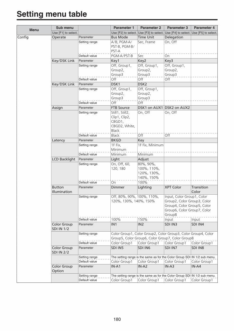
180
MenuSub menu Parameter 1 Parameter 2 Parameter 3 Parameter 4
Use [F1] to select. Use [F2] to select. Use [F3] to select. Use [F4] to select. Use [F5] to select.Config Operate Parameter Bus Mode Time Unit Delegation
Setting range A/B, PGM-A/PST-B, PGM-B/PST-A
Sec, Frame On, Off
Default value PGM-A/PST-B Sec On
Key/DSK Link Parameter Key1 Key2 Key3
Setting range Off, Group1, Group2, Group3
Off, Group1, Group2, Group3
Off, Group1, Group2, Group3
Default value Off Off Off
Key/DSK Link Parameter DSK1 DSK2
Setting range Off, Group1, Group2, Group3
Off, Group1, Group2, Group3
Default value Off Off
Assign Parameter FTB Source DSK1 on AUX1 DSK2 on AUX2
Setting range Still1, Still2, Clip1, Clip2, CBGD1, CBGD2, White, Black
On, Off On, Off
Default value Black Off Off
Latency Parameter BKGD Key
Setting range 1F Fix, Minimum
1F Fix, Minimum
Default value Minimum Minimum
LCD Backlight Parameter Light Adjust
Setting range On, Off, 60, 120, 180
80%, 90%, 100%, 110%, 120%, 130%, 140%, 150%
Default value On 100%
Button Illumination
Parameter Dimmer Lighting XPT Color Transition Color
Setting range Off, 80%, 90%, 100%, 110%, 120%, 130%, 140%, 150%
Input, Color Group1, Color Group2, Color Group3, Color Group4, Color Group5, Color Group6, Color Group7, Color Group8
Default value 100% 150% Input Input
Color Group SDI IN 1/2
Parameter IN1 IN2 SDI IN3 SDI IN4
Setting range Color Group1, Color Group2, Color Group3, Color Group4, Color Group5, Color Group6, Color Group7, Color Group8
Default value Color Group1 Color Group1 Color Group1 Color Group1
Color Group SDI IN 2/2
Parameter SDI IN5 SDI IN6 SDI IN7 SDI IN8
Setting range The setting range is the same as for the Color Group SDI IN 1/2 sub menu.Default value Color Group1 Color Group1 Color Group1 Color Group1
Color Group Option
Parameter IN-A1 IN-A2 IN-A3 IN-A4
Setting range The setting range is the same as for the Color Group SDI IN 1/2 sub menu.Default value Color Group1 Color Group1 Color Group1 Color Group1
Setting menu table

181
MenuSub menu Parameter 1 Parameter 2 Parameter 3 Parameter 4
Use [F1] to select. Use [F2] to select. Use [F3] to select. Use [F4] to select. Use [F5] to select.Config Color Group
OptionParameter IN-B1 IN-B2 IN-B3 IN-B4
Setting range The setting range is the same as for the Color Group SDI IN 1/2 sub menu.Default value Color Group1 Color Group1 Color Group1 Color Group1
Color Group Internal
Parameter Black CBGD 1 CBGD 2 CBAR
Setting range The setting range is the same as for the Color Group SDI IN 1/2 sub menu.Default value Color Group1 Color Group1 Color Group1 Color Group1
Color Group Still
Parameter Still 1V Still 1K Still 2V Still 2K
Setting range The setting range is the same as for the Color Group SDI IN 1/2 sub menu.Default value Color Group1 Color Group1 Color Group1 Color Group1
Color Group Clip
Parameter Clip 1V Clip 1K Clip 2V Clip 2K
Setting range The setting range is the same as for the Color Group SDI IN 1/2 sub menu.Default value Color Group1 Color Group1 Color Group1 Color Group1
Color Group Other 1/2
Parameter CLN ME PGM Key Out Shift
Setting range The setting range is the same as for the Color Group SDI IN 1/2 sub menu.Default value Color Group1 Color Group1 Color Group1 Color Group1
Color Group Other 2/2
Parameter Macro Attach
Setting range The setting range is the same as for the Color Group SDI IN 1/2 sub menu.Default value Color Group1
Color Group Transition
Parameter AUTO CUT MIX WIPE
Setting range The setting range is the same as for the Color Group SDI IN 1/2 sub menu.Default value Color Group1 Color Group1 Color Group1 Color Group1
Color Group Next Trans
Parameter BKGD KEY
Setting range The setting range is the same as for the Color Group SDI IN 1/2 sub menu.
Default value Color Group1 Color Group1
Color Group KEY ON
Parameter KEY1 ON KEY2 ON KEY3 ON
Setting range The setting range is the same as for the Color Group SDI IN 1/2 sub menu.
Default value Color Group1 Color Group1 Color Group1
Color Group DSK/FTB ON
Parameter DSK1 ON DSK2 ON FTB ON
Setting range The setting range is the same as for the Color Group SDI IN 1/2 sub menu.
Default value Color Group1 Color Group1 Color Group1
Button Color Group1
Parameter R G B
Setting range 0.0 to 1.5 0.0 to 1.5 0.0 to 1.5
Default value 0.1 0.1 0.1
Setting menu table

182
MenuSub menu Parameter 1 Parameter 2 Parameter 3 Parameter 4
Use [F1] to select. Use [F2] to select. Use [F3] to select. Use [F4] to select. Use [F5] to select.Config Button Color
Group2 Parameter R G B
Setting range 0.0 to 1.5 0.0 to 1.5 0.0 to 1.5
Default value 0.1 0.1 0.0
Button Color Group3
Parameter R G B
Setting range 0.0 to 1.5 0.0 to 1.5 0.0 to 1.5
Default value 0.0 0.1 0.1
Button Color Group4
Parameter R G B
Setting range 0.0 to 1.5 0.0 to 1.5 0.0 to 1.5
Default value 0.0 0.1 0.1
Button Color Group5
Parameter R G B
Setting range 0.0 to 1.5 0.0 to 1.5 0.0 to 1.5
Default value 0.1 0.0 0.1
Button Color Group6
Parameter R G B
Setting range 0.0 to 1.5 0.0 to 1.5 0.0 to 1.5
Default value 0.1 0.0 0.0
Button Color Group7
Parameter R G B
Setting range 0.0 to 1.5 0.0 to 1.5 0.0 to 1.5
Default value 0.0 0.0 0.1
Button Color Group8
Parameter R G B
Setting range 0.0 to 1.5 0.0 to 1.5 0.0 to 1.5
Default value 0.0 0.0 0.0
WFM Parameter Style Mode
Setting range Parade, Overlay YPbPr, RGB, Y
Default value Parade YPbPr
Vector Parameter Bar Target
Setting range 75%, 100%
Default value 100%
User Button1-4 Parameter User1 User2 User3 User4
Setting range Key1 PVW, Key2 PVW, Key3 PVW, DSK1 PVW, DSK2 PVW, GPII-EN, GPIO-EN, SHIFT, AUX Trans, AUX1 Trans, AUX2 Trans, DSK1 on AUX1, DSK2 on AUX2, Effect Dissolve, Macro Attach, None
Default value Key1 PVW Key2 PVW Key3 PVW DSK1 PVW
User Button5-8 Parameter User5 User6 User7 User8
Setting range The setting range is the same as for the User Button1-4 sub menu.Default value DSK2 PVW AUX Trans Effect Dissolve SHIFT
GPI-In Setting Parameter GPI-In Enable AUX Sel
Setting range On, Off AUX1, AUX2, AUX3, AUX4
Default value On AUX1
GPI-In Port1/2 Parameter Port1 Assign Port2 Assign Port3 Assign Port4 Assign
Setting range No Assign, AUTO, CUT, KEY1 ON, KEY2 ON, KEY3 ON, DSK1 ON, DSK2 ON, FTB ON, BKGD AUTO, BKGD CUT, KEY1 AUTO, KEY1 CUT, REC Still1, REC Still2, REC Clip1, PLAY Clip1, STOP Clip1, REC Clip2, PLAY Clip2, STOP Clip2, AUX XPT1 to 24, TlyG1 DSBL, TlyG2 DSBL, AUX Tly DSBL, MACRO001 to 100, MACRO Cancel
Default value No Assign No Assign No Assign No Assign
Setting menu table

183
MenuSub menu Parameter 1 Parameter 2 Parameter 3 Parameter 4
Use [F1] to select. Use [F2] to select. Use [F3] to select. Use [F4] to select. Use [F5] to select.Config GPI-In Port2/2 Parameter Port5 Assign Port6 Assign Port7 Assign Port8 Assign
Setting range The setting range is the same as for the GPI-In Port1/2 sub menu.Default value No Assign No Assign No Assign No Assign
GPI-Out Setting
Parameter GPI-Out Enable AUX Tly Sel
Setting range On, Off AUX1, AUX2, AUX3, AUX4
Default value On AUX1
GPI-Out Port1/5
Parameter Port1 Assign Port2 Assign Port3 Assign Port4 Assign
Setting range No Assign, AUTO, CUT, KEY1 ON, KEY2 ON, KEY3 ON, DSK1 ON, DSK2 ON, FTB ON, BKGD AUTO, BKGD CUT, KEY1 AUTO, KEY1 CUT, TlyG1 SDI IN1 to TlyG1 SDI IN8, TlyG1 HDMI IN1, TlyG1 HDMI IN2, TlyG1 IN-A1 to TlyG1 IN-A4, TlyG1 IN-B1 to TlyG1 IN-B4, TlyG2 SDI IN1 to TlyG2 SDI IN8, TlyG2 HDMI IN1, TlyG2 HDMI IN2, TlyG2 IN-A1 to TlyG2 IN-A4, TlyG2 IN-B1 to TlyG2 IN-B4, AuxTly SDI IN1 to AuxTly SDI IN8, AuxTly HDMI IN1, AuxTly HDMI IN2, AuxTly IN-A1 to AuxTly IN-A4, AuxTly IN-B1 to AuxTly IN-B4, Event MEM
Default value No Assign No Assign No Assign No Assign
GPI-Out Port2/5
Parameter Port5 Assign Port6 Assign Port7 Assign Port8 Assign
Setting range The setting range is the same as for the GPI-Out Port1/5 sub menu.Default value No Assign No Assign No Assign No Assign
GPI-Out Port3/5
Parameter Port9 Assign Port10 Assign Port11 Assign Port12 Assign
Setting range The setting range is the same as for the GPI-Out Port1/5 sub menu.Default value No Assign No Assign No Assign No Assign
GPI-Out Port4/5
Parameter Port13 Assign Port14 Assign Port15 Assign Port16 Assign
Setting range The setting range is the same as for the GPI-Out Port1/5 sub menu.Default value No Assign No Assign No Assign No Assign
GPI-Out Port5/5
Parameter Port17 Assign Port18 Assign Port19 Assign
Setting range The setting range is the same as for the GPI-Out Port1/5 sub menu.
Default value No Assign No Assign No Assign
System Menu Parameter Lock
Setting range On, Off
Default value Off
Setting menu table

184
MenuSub menu Parameter 1 Parameter 2 Parameter 3 Parameter 4
Use [F1] to select. Use [F2] to select. Use [F3] to select. Use [F4] to select. Use [F5] to select.Config Key Source
Signal Coupling1
Parameter Fill/Source
Setting range Fill To Source, Source To Fill
Default value Fill To Source
Key Source Signal Coupling2
Parameter IN1 IN2 SDI IN3 SDI IN4
Setting range IN1, IN2, SDI IN3, SDI IN4, SDI IN5, SDI IN6, SDI IN7, SDI IN8, IN-A1, IN-A2, IN-A3, IN-A4, IN-B1, IN-B2, IN-B3, IN-B4, Black, CBGD 1, CBGD 2, CBAR, Still 1V, Still 1K, Still 2V, Still 2K, Clip 1V, Clip 1K, Clip 2V, Clip 2K
Default value IN1 IN2 SDI IN3 SDI IN4
Key Source Signal Coupling3
Parameter SDI IN5 SDI IN6 SDI IN7 SDI IN8
Setting range The setting range is the same as for the Key Source Signal Coupling2 sub menu.
Default value SDI IN5 SDI IN6 SDI IN7 SDI IN8
Key Source Signal Coupling4
Parameter IN-A1 IN-A2 IN-A3 IN-A4
Setting range The setting range is the same as for the Key Source Signal Coupling2 sub menu.
Default value IN-A1 IN-A2 IN-A3 IN-A4
Key Source Signal Coupling5
Parameter IN-B1 IN-B2 IN-B3 IN-B4
Setting range The setting range is the same as for the Key Source Signal Coupling2 sub menu.
Default value IN-B1 IN-B2 IN-B3 IN-B4
Key Source Signal Coupling6
Parameter Black CBGD 1 CBGD 2 CBAR
Setting range The setting range is the same as for the Key Source Signal Coupling2 sub menu.
Default value Black CBGD 1 CBGD 2 CBAR
Key Source Signal Coupling7
Parameter Still 1V Still 1K Still 2V Still 2K
Setting range The setting range is the same as for the Key Source Signal Coupling2 sub menu.
Default value Still 1V Still 1K Still 2V Still 2K
Key Source Signal Coupling8
Parameter Clip 1V Clip 1K Clip 2V Clip 2K
Setting range The setting range is the same as for the Key Source Signal Coupling2 sub menu.
Default value Clip 1V Clip 1K Clip 2V Clip 2K
System/Locked
(When locked)
(All menus grayed out)
Setting menu table

185
MenuSub menu Parameter 1 Parameter 2 Parameter 3 Parameter 4
Use [F1] to select. Use [F2] to select. Use [F3] to select. Use [F4] to select. Use [F5] to select.System
(When unlocked)
Format Parameter Format Switcher Mode Color Space
Setting range 2160/59.94P, 50P, 29.97P, 25P, 24P, 23.98P1080/59.94P, 50P, 29.97Psf, 25Psf, 24Psf, 23.98Psf, 59.94i, 50i720/59.94P, 50P
2K, 4K HDR, BT.2020, HDR BT.709, SDR BT.709
Default value 1080/59.94i 2K SDR BT.709
Output Phase Parameter System H-Phase V-Phase
Setting range 0H, 1H � 0.50 to 0.49 � 100 to 100
Default value 0H 0 0
Reference Parameter Sync BB Setup Gen Lock
Setting range BB, BB Advanced, Tri-level Sync, Internal
0IRE, 7.5IRE Locked, Unlock
Default value BB 7.5IRE Unlock
Ancillary Parameter AUX PGM PVW MV
Setting range On, Off On, Off On, Off PGM, PVW, Off
Default value Off Off Off Off
Test Tone Parameter Color Bar
Setting range Normal, Low, Off
Default value Normal
Alarm Parameter Power Fan Temperature
Setting range Alarm, No Alarm
Alarm, No Alarm
Alarm, No Alarm
Default value
Initial Parameter Initial Fader Initial
Setting range Execute Execute
Default value
Network1 Parameter IP Address
Setting range 0 to 255
Default value 192.168.0.8
Network2 Parameter Subnet Mask
Setting range 0 to 255
Default value 192.168.0.8
Network3 Parameter Default Gateway
Setting range 0 to 255
Default value 192.168.0.8
Network4 Parameter MAC Address
Setting range Display only
Default value
ExtPanel Info Parameter PortNo
Setting range 62000 to 65535
Default value 62010
Setting menu tableSetting menu table

186
MenuSub menu Parameter 1 Parameter 2 Parameter 3 Parameter 4
Use [F1] to select. Use [F2] to select. Use [F3] to select. Use [F4] to select. Use [F5] to select.System
(When unlocked)
ExtPanelip SMEMRecall1
Parameter ME DSK AUX
Setting range On, Off On, Off On, Off
Default value Off Off Off
ExtPanelip SMEMRecall2
Parameter CBGD XPT
Setting range On, Off On, Off
Default value Off Off
ExtControl Switcher
Parameter Disable/Enable PortNo IntervalTime
Setting range Disable, Enable 62000 to 65535 0ms, 16ms, 32ms, 48ms 64ms, 80ms
Default value Disable 62000 16ms
ExtControl AUX Panel1
Parameter IP Address1 IP Address2 IP Address3 IP Address4
Setting range 0 to 255 0 to 255 0 to 255 0 to 255
Default value 0.0.0.0 0.0.0.0 0.0.0.0 0.0.0.0
ExtControl AUX Panel2
Parameter IP Address5 IP Address6 IP Address7 IP Address8
Setting range 0 to 255 0 to 255 0 to 255 0 to 255
Default value 0.0.0.0 0.0.0.0 0.0.0.0 0.0.0.0
ExtControl AUX Panel3
Parameter IP Address9 IP Address10 IP Address11 IP Address12
Setting range 0 to 255 0 to 255 0 to 255 0 to 255
Default value 0.0.0.0 0.0.0.0 0.0.0.0 0.0.0.0
ExtControl AUX Panel4
Parameter IP Address13 IP Address14 IP Address15 IP Address16
Setting range 0 to 255 0 to 255 0 to 255 0 to 255
Default value 0.0.0.0 0.0.0.0 0.0.0.0 0.0.0.0
ExtControl AUX Panel5
Parameter IP Address17 IP Address18 IP Address19 IP Address20
Setting range 0 to 255 0 to 255 0 to 255 0 to 255
Default value 0.0.0.0 0.0.0.0 0.0.0.0 0.0.0.0
ExtControl AUX Panel6
Parameter PortNo
Setting range 60000 to 65535
Default value 65000
Macro Trigger Control1
Parameter Disable/Enable
Setting range Disable, Enable
Default value Disable
Macro Trigger Control2
Parameter IP Address1 Macro1 IP Address2 Macro2
Setting range 0 to 255 No Assign,Macro001 to Macro100
0 to 255 No Assign,Macro001 to Macro100
Default value 0.0.0.0 No Assign 0.0.0.0 No Assign
Setting menu table

187
MenuSub menu Parameter 1 Parameter 2 Parameter 3 Parameter 4
Use [F1] to select. Use [F2] to select. Use [F3] to select. Use [F4] to select. Use [F5] to select.System
(When unlocked)
Macro Trigger Control3
Parameter IP Address3 Macro3 IP Address4 Macro4
Setting range 0 to 255 No Assign,Macro001 to Macro100
0 to 255 No Assign,Macro001 to Macro100
Default value 0.0.0.0 No Assign 0.0.0.0 No Assign
Macro Trigger Control4
Parameter IP Address5 Macro5 IP Address6 Macro6
Setting range 0 to 255 No Assign,Macro001 to Macro100
0 to 255 No Assign,Macro001 to Macro100
Default value 0.0.0.0 No Assign 0.0.0.0 No Assign
Macro Trigger Control5
Parameter IP Address7 Macro7 IP Address8 Macro8
Setting range 0 to 255 No Assign,Macro001 to Macro100
0 to 255 No Assign,Macro001 to Macro100
Default value 0.0.0.0 No Assign 0.0.0.0 No Assign
Macro Trigger Control6
Parameter IP Address9 Macro9 IP Address10 Macro10
Setting range 0 to 255 No Assign,Macro001 to Macro100
0 to 255 No Assign,Macro001 to Macro100
Default value 0.0.0.0 No Assign 0.0.0.0 No Assign
Macro Trigger Control7
Parameter IP Address11 Macro11 IP Address12 Macro12
Setting range 0 to 255 No Assign,Macro001 to Macro100
0 to 255 No Assign,Macro001 to Macro100
Default value 0.0.0.0 No Assign 0.0.0.0 No Assign
Macro Trigger Control8
Parameter IP Address13 Macro13 IP Address14 Macro14
Setting range 0 to 255 No Assign,Macro001 to Macro100
0 to 255 No Assign,Macro001 to Macro100
Default value 0.0.0.0 No Assign 0.0.0.0 No Assign
Macro Trigger Control9
Parameter IP Address15 Macro15 IP Address16 Macro16
Setting range 0 to 255 No Assign,Macro001 to Macro100
0 to 255 No Assign,Macro001 to Macro100
Default value 0.0.0.0 No Assign 0.0.0.0 No Assign
Macro Trigger Control10
Parameter IP Address17 Macro17 IP Address18 Macro18
Setting range 0 to 255 No Assign,Macro001 to Macro100
0 to 255 No Assign,Macro001 to Macro100
Default value 0.0.0.0 No Assign 0.0.0.0 No Assign
Macro Trigger Control11
Parameter IP Address19 Macro19 IP Address20 Macro20
Setting range 0 to 255 No Assign,Macro001 to Macro100
0 to 255 No Assign,Macro001 to Macro100
Default value 0.0.0.0 No Assign 0.0.0.0 No Assign
Setting menu table

188
MenuSub menu Parameter 1 Parameter 2 Parameter 3 Parameter 4
Use [F1] to select. Use [F2] to select. Use [F3] to select. Use [F4] to select. Use [F5] to select.System
(When unlocked)
Tally Mode Parameter Tally Target
Setting range On, Off
Default value On
Tally MV Color Parameter Group1 Group2 Group3 Group4
Setting range Red Red, Green, Yellow, Orange
Default value Red Green Yellow Orange
Tally Target Parameter Group1 Group2 Group3 Group4
Setting range Off, PGM, CLN, ME PGM, Key Out, AUX1, AUX2, AUX3, AUX4
Off, PGM, PVW, CLN, ME PGM, Key Out, AUX1, AUX2, AUX3, AUX4
Default value PGM PVW CLN AUX1
Now Parameter Get Date Get Time
Setting range Execute Execute
Default value
Date Parameter Year Month Day Set
Setting range 2000 to 2037 1 to 12 1 to 31 Execute
Default value � � �
Time Parameter Hour Minute Second Set
Setting range 0 to 23 0 to 59 0 to 59 Execute
Default value � � �
System Version Parameter System Version Set Delete
Setting range Version number Execute Execute
Default value
Option Parameter Slot A Slot B
Setting range SDI-IN, HDMI-IN, SDI-OUT, HDMI-OUT, 4K-DVE, None
Default value
Setting menu table

189
Appendix (glossary)
Defined below are the terms used in this manual.
Word Explanation
AB Bus system A bus control mode. By executing a transition, the A bus and B bus signals are output to the program images alternately.
Ancillary Data The auxiliary data other than the video signals which is transmitted inside the data stream of the video serial interface. The data superimposed on the vertical blanking period is referred to as the V ancillary data (VANC).
Aspect ratio The ratio between the horizontal and vertical dimensions of an image or screen.It is 16:9 for the HD format and 4:3 for the SD format.
AUX[Auxiliary Bus]
A spare bus which can be switched by signals other than the main line output signals.
BB[Black burst]
The black burst signal. A full-screen black level composite signal which is used as the reference signal for gen-lock.
Border The area or margin that is added to the edge of a wipe or key.Its width and color can be adjusted. The defocusing of the area around a border is referred to as the soft effect.
Chroma key This refers to the function for creating the key signals based on the color information of the video signals and combining the keys.
Clip The threshold level of the luminance when key signals are created from a key source.
Color Background The signals which are output from the internal color generator and used as the background image.
Cut This refers to the effect where the display is instantly switched to the next image.
Density A parameter which is used to adjust the density of the key signals.
Down Converter This is the function that converts material in the 4K format into the 2K/HD format.
DSK [Downstream Key] This refers to the key combination process which is performed at the end of the mix effect. The key is always combined with the foremost image.
DVE [Digital Video Effect] This refers to the transition patterns accompanying size reductions or slide effects.
Embedded Audio This refers to the audio data packets which are transferred inside the data stream of the video serial interface.
Flip Flop system(PGM/PST system)
A bus control mode. The signals selected by the program bus are always output as the program images. By executing a transition, the program bus and preset bus signals are switched over.
Flying Key This function uses DVE effects to move, expand or reduce key signals.
Frame Synchronizer A function which matches the synchronization of non-synchronized video input signals.
Freeze A function which continues the display of the same image, creating the impression that the image has been “frozen”.
FTB [Fade to Black] This is the effect where the background image is faded out to the black screen.
Genlock A function for synchronizing the video signals using an external sync signal as the reference.
GPI[General Purpose Interface]
Interface signals which control auto transition from an external source.
Hue The color tone of the video signals.
IRE A unit used for video signal levels.The setup level (black level) of the signals is expressed as 0 IRE, 7.5 IRE, etc.
Key Edge The border or shadow added to the edges of keys.

190
Word Explanation
Key Fill The signal that uses key combination processing to fill in the areas left blank by the key signals.
Key Gain A parameter which is used to adjust the amplitude of the key signals.
Key Invert A function which inverts the key signals.
Key Mask This is the function that specifies the area for key combination using the box pattern, etc. When only part of the area of the key signals is used, key combination is executed with the unnecessary area masked.
Key Source The video signals for creating the key signals.
Line Synchronizer A function to automatically adjust the input image signal phase to the horizontal synchronization reference signal phase.
Linear Key The function which combines keys using monochrome key signals with gradations in its outlines as a reference.
Lum[Luminance]
The brightness portion of the video signals.
Luminance Key The function which creates key signals based on the luminance (brightness) information of the video signals to combine keys.
ME[Mix Effect]
A video effect device which combines a number of video signals to create mix, wipe, key and other video signals.
Mix The picture-changing effect produced by overlapping one image with the next.It is also referred to as “dissolve”.
Multi View Display This function combines multiple materials and displays them on one screen. PGM, PVW and the input material can be previewed at the same time on a single screen.
PinP [Picture in Picture] This function combines a sub screen image with the background image.
PVW[Preview]
The function for checking ahead of time the image which will be output after the next transition. The image is output from the PVW system.
PGM[Program Bus]
The bus which always carries the program output signals.
PST[Preset Bus]
The bus which carries the program output signals after the next background transition.
Sat[Saturation]
This refers to the intensity of the color chrominance level of video signals.
SDI[Serial Digital Interface]
The standard by which video signals in various SD and HD formats are transmitted along a single coaxial cable.
Self Key A function that creates key signals from key fill signals for combining keys.
Setup Data The memory in which the control panel statuses can be saved and recalled.The button selection statuses as well as the border, color and other setting information can be saved in this memory.
Tally The signal which outputs the program output statuses of the input signals to an external device. The LED that indicates the program output status on the control panel is also referred to as tally.
Transition A function that switches from one image to another.Wipe, mix and other effects are available for the images during switching.
Tri-level Sync The sync signal used for HD formats.
Trimming This is the function that eliminates the unnecessary parts at the top, bottom, left and/or right of the images which are combined using the PinP function.
Appendix (glossary)

191
Word Explanation
Up Converter This is the function that converts material in the 2K/HD format into the 4K format which yields a high resolution.
Video Memory This is the memory in which the images (still images and moving images) with key signals can be stored.
Wipe A video effect in which one image is gradually replaced by another as the boundary between the two is moved using a preselected pattern.
Appendix (glossary)

192
AAUX bus crosspoint button ................................... 18
BBackground ........................................................... 157
3D Modify ........................................................... 157Border ................................................................. 157Border Color ....................................................... 157Clip Trans Sync ................................................... 157Modify ................................................................. 157Position ............................................................... 157Transition Margin ................................................ 157Transition Time ................................................... 157
BKGD, KEY pattern selector button ...................... 19
CCamera .................................................................. 167
ABB .................................................................... 168AWB ................................................................... 167Camera Control .................................................. 167Camera Information ............................................ 167Control Speed .................................................... 167Gain1 .................................................................. 168Gain2 .................................................................. 168Lens Control ....................................................... 167Lock .................................................................... 168OSD Menu & Color Bars .................................... 167Pedestal .............................................................. 168Preset Settings ................................................... 168
Chroma Key ........................................................... 163Adjust ................................................................. 163Auto Compute ..................................................... 163Chroma Key ........................................................ 163Fine Tuning ......................................................... 163Sampling ............................................................ 163Sampling Area .................................................... 163
Color Background ................................................ 158CBGD1 Main ...................................................... 158CBGD1 Move ..................................................... 158CBGD1 Sub ........................................................ 158CBGD1 Wash ..................................................... 158CBGD1 Wave ..................................................... 158CBGD2 Main ...................................................... 158CBGD2 Move ..................................................... 158CBGD2 Sub ........................................................ 158CBGD2 Wash ..................................................... 158CBGD2 Wave ..................................................... 158
Config .................................................................... 180Assign ................................................................. 180Button Color Group1 .......................................... 181Button Color Group2 .......................................... 182Button Color Group3 .......................................... 182Button Color Group4 .......................................... 182Button Color Group5 .......................................... 182
Button Color Group6 .......................................... 182Button Color Group7 .......................................... 182Button Color Group8 .......................................... 182Button Illumination .............................................. 180Color Group Clip ................................................. 181Color Group DSK/FTB ON ................................. 181Color Group Internal ........................................... 181Color Group KEY ON ......................................... 181Color Group Next Trans ...................................... 181Color Group Option ............................................ 180Color Group Other 1/2 ........................................ 181Color Group Other 2/2 ........................................ 181Color Group SDI IN 1/2 ...................................... 180Color Group SDI IN 2/2 ...................................... 180Color Group Still ................................................. 181Color Group Transition ........................................ 181GPI-In Port1/2 ..................................................... 182GPI-In Port2/2 ..................................................... 183GPI-In Setting ..................................................... 182GPI-Out Port1/5 .................................................. 183GPI-Out Port2/5 .................................................. 183GPI-Out Port3/5 .................................................. 183GPI-Out Port4/5 .................................................. 183GPI-Out Port5/5 .................................................. 183GPI-Out Setting .................................................. 183Key/DSK Link ..................................................... 180Key Source Signal Coupling1 ............................. 184Key Source Signal Coupling2 ............................. 184Key Source Signal Coupling3 ............................. 184Key Source Signal Coupling4 ............................. 184Key Source Signal Coupling5 ............................. 184Key Source Signal Coupling6 ............................. 184Key Source Signal Coupling7 ............................. 184Key Source Signal Coupling8 ............................. 184Latency ............................................................... 180LCD Backlight ..................................................... 180Operate .............................................................. 180System Menu ...................................................... 183User Button1-4 ................................................... 182User Button5-8 ................................................... 182Vector ................................................................. 182WFM ................................................................... 182
DDSK1 ...................................................................... 163
Adjust ................................................................. 163DSK1 .................................................................. 163DSK On .............................................................. 164DSK Priority ........................................................ 164DSK Signal Coupling .......................................... 164Fill Matte ............................................................. 163Mask ................................................................... 164Mask Adjust ........................................................ 164PinP .................................................................... 164PinP Border ........................................................ 164PinP Position ...................................................... 164PinP Sync ........................................................... 164PinP Trim ............................................................ 164PinP Trim Adjust ................................................. 164
Index

193
DSK2 ...................................................................... 165Adjust ................................................................. 165DSK1 .................................................................. 165DSK On .............................................................. 165DSK Priority ........................................................ 165DSK Signal Coupling .......................................... 165Fill Matte ............................................................. 165Mask ................................................................... 165Mask Adjust ........................................................ 165
EEvent Memory ....................................................... 172
Event Duration .................................................... 172Mark ................................................................... 172Path .................................................................... 172Play ..................................................................... 172Register .............................................................. 172Target Select1 .................................................... 172Target Select2 .................................................... 172Timeline .............................................................. 172Total Duration ..................................................... 172
FFader lever .............................................................. 21
IInput ............................................................... 175, 178
Camera Settings1 ............................................... 178Camera Settings2 ............................................... 178Camera Settings3 ............................................... 178Camera Settings4 ............................................... 178Input ................................................................... 175
Input (HDMI) .......................................................... 177C/C Matrix B ....................................................... 177C/C Matrix R/G ................................................... 177C/C Operation ..................................................... 177C/C Process ....................................................... 177C/C Setting ......................................................... 177C/C Tone1 Black ................................................. 177C/C Tone2 Gray L ............................................... 177C/C Tone3 Gray H .............................................. 177C/C Tone4 White ................................................. 177Freeze ................................................................ 177HDMI Input ......................................................... 177HDMI Status ....................................................... 177Limited ................................................................ 177Name .................................................................. 177
Input (SDI) ............................................................. 176C/C Matrix B ....................................................... 176C/C Matrix R/G ................................................... 176C/C Operation ..................................................... 176C/C Process ....................................................... 176C/C Setting ......................................................... 176C/C Tone1 Black ................................................. 176C/C Tone2 Gray L ............................................... 176
C/C Tone3 Gray H .............................................. 176C/C Tone4 White ................................................. 176Freeze ................................................................ 176FS ....................................................................... 176Name .................................................................. 176Status ................................................................. 176Up/Down Converter ............................................ 176
KKey1 ....................................................................... 159
3D Modify ........................................................... 159Adjust ................................................................. 159Edge1 ................................................................. 159Edge2 ................................................................. 159Edge Color ......................................................... 159Fill Matte ............................................................. 159Flying Key Aspect ............................................... 159Flying Key Rotation ............................................ 159Flying Key Rotation/Size ..................................... 159Key1 ................................................................... 159Key On ................................................................ 160Key Priority ......................................................... 160Key Signal Coupling ........................................... 160Mask ................................................................... 160Mask Adjust ........................................................ 160PinP .................................................................... 160PinP Border ........................................................ 160PinP Position ...................................................... 160PinP Sync ........................................................... 160PinP Trim ............................................................ 160PinP Trim Adjust ................................................. 160Position ............................................................... 159Transition ............................................................ 159
Key2 ....................................................................... 161Adjust ................................................................. 161Edge1 ................................................................. 161Edge2 ................................................................. 161Edge Color ......................................................... 161Fill Matte ............................................................. 161Key1 ................................................................... 161Key On ................................................................ 162Key Priority ......................................................... 162Key Signal Coupling ........................................... 162Mask ................................................................... 161Mask Adjust ........................................................ 161PinP .................................................................... 161PinP Border ........................................................ 161PinP Position ...................................................... 161PinP Sync ........................................................... 162PinP Trim ............................................................ 162PinP Trim Adjust ................................................. 162
Key3 ....................................................................... 162Adjust ................................................................. 162Fill Matte ............................................................. 162Key1 ................................................................... 162Key On ................................................................ 162Key Priority ......................................................... 162Key Signal Coupling ........................................... 162
Index

194
Mask ................................................................... 162Mask Adjust ........................................................ 162
LLAN cable .............................................................. 129
MMacro ..................................................................... 171
Attach ................................................................. 171Insert Delay ........................................................ 171Macro Assign 1/6 ................................................ 171Macro Assign 2/6 ................................................ 171Macro Assign 3/6 ................................................ 171Macro Assign 4/6 ................................................ 171Macro Assign 5/6 ................................................ 171Macro Assign 6/6 ................................................ 171Store Select1 ...................................................... 171Store Select2 ...................................................... 171
Memory operation button ...................................... 19
Menu ........................................................................ 28
Menu selection buttons ................................... 23, 28
Multi View Display ................................................. 173Display ........................................................ 174, 175MV1 Frame ......................................................... 174MV1 Pattern 1/4 .................................................. 174MV1 Pattern 2/4 .................................................. 174MV1 Pattern 3/4 .................................................. 174MV1 Pattern 4/4 .................................................. 174MV1 Split ............................................................ 174MV1 Tally Group1 ............................................... 174MV1 Tally Group2 ............................................... 174MV2 Frame ......................................................... 175MV2 Pattern 1/4 .................................................. 175MV2 Pattern 2/4 .................................................. 175MV2 Pattern 3/4 .................................................. 175MV2 Pattern 4/4 .................................................. 175MV2 Split ............................................................ 175MV2 Tally Green ................................................. 175MV2 Tally Red .................................................... 175
OOutput .................................................................... 178
Output ................................................................. 178
Output (HDMI) ....................................................... 179Assign ................................................................. 179HDMI Output ...................................................... 179
Output (SDI) .......................................................... 178Assign ................................................................. 178Down Converter .................................................. 178
PPGM/A bus crosspoint button ............................... 18
Positioner ................................................................ 24
Project File ............................................................ 168Last Load Date ................................................... 168Last Load File ..................................................... 168Project File ......................................................... 168Target Select1 .................................................... 168Target Select2 .................................................... 168
PST/B bus crosspoint button ................................ 18
RRotary encoder ............................................ 23, 24, 28
SSD Card ................................................................. 169
Card Information ................................................. 169Card Management .............................................. 169Create Thumbnail ............................................... 169File ...................................................................... 169Mode .................................................................. 169Target Select1 .................................................... 169Target Select2 .................................................... 169
Shot Memory ......................................................... 172Path .................................................................... 172Register .............................................................. 172Target Select1 .................................................... 172Target Select2 .................................................... 172
System ................................................................... 185Alarm .................................................................. 185Ancillary .............................................................. 185Date .................................................................... 188ExtControl AUX Panel1 ...................................... 186ExtControl AUX Panel2 ...................................... 186ExtControl AUX Panel3 ...................................... 186ExtControl AUX Panel4 ...................................... 186ExtControl AUX Panel5 ...................................... 186ExtControl AUX Panel6 ...................................... 186ExtControl Switcher ............................................ 186ExtPanel Info ...................................................... 185ExtPanelip SMEMRecall1 ................................... 186ExtPanelip SMEMRecall2 ................................... 186Format ................................................................ 185Initial ................................................................... 185Macro Trigger Control1 ....................................... 186Macro Trigger Control2 ....................................... 186Macro Trigger Control3 ....................................... 187Macro Trigger Control4 ....................................... 187Macro Trigger Control5 ....................................... 187Macro Trigger Control6 ....................................... 187Macro Trigger Control7 ....................................... 187Macro Trigger Control8 ....................................... 187Macro Trigger Control9 ....................................... 187
Index

195
Macro Trigger Control10 ..................................... 187Macro Trigger Control11 ..................................... 187Network1 ............................................................ 185Network2 ............................................................ 185Network3 ............................................................ 185Network4 ............................................................ 185Now .................................................................... 188Option ................................................................. 188Output Phase ..................................................... 185Reference ........................................................... 185System Version ................................................... 188Tally Mode .......................................................... 188Tally MV Color .................................................... 188Tally Target .......................................................... 188Test Tone ............................................................ 185Time ................................................................... 188
TTime ....................................................................... 166
AUX1 BUS Trans ................................................ 166AUX2 BUS Trans ................................................ 166BKGD ................................................................. 166DSK1 .................................................................. 166DSK2 .................................................................. 166Effect Dissolve .................................................... 166FTB ..................................................................... 166Key1 ................................................................... 166Key2 ................................................................... 166Key3 ................................................................... 166
UUser button ............................................................. 20
VVideo Memory ....................................................... 170
Limit Time ........................................................... 170Memory .............................................................. 170Play Mode1 ......................................................... 170Play Mode2 ......................................................... 170Rec1 ................................................................... 170Rec2 ................................................................... 170Rec3 ................................................................... 170Video Memory1 .................................................. 170Video Memory2 .................................................. 170Video Memory3 .................................................. 170
XXPT ......................................................................... 173
XPT Assign 1/6 ................................................... 173XPT Assign 2/6 ................................................... 173XPT Assign 3/6 ................................................... 173XPT Assign 4/6 ................................................... 173XPT Assign 5/6 ................................................... 173XPT Assign 6/6 ................................................... 173XPT Setting ........................................................ 173XPT Switch ......................................................... 173
Index

Web Site: https://www.panasonic.com
©Panasonic Corporation 2020