OPERATING INSTRUCTIONS english MAXIMA 1000 … · OPERATING INSTRUCTIONS english MAXIMA 1000 (from...
24
3 OPERATING INSTRUCTIONS english MAXIMA 1000 (from SN RB403109) and MAXIMA 1300 1. INTRODUCTION This guide has been prepared for the operator of Carrier Transicold refrigeration units. It contains basic instructions for the daily operation of the refrigeration unit as well as safety information, troubleshooting tips, and other information that will help you to deliver the load in the best possible condition. Please take the time to read the information contained in this booklet and refer to it whenever you have a questionabouttheoperationofyourCarrierTransicoldunit.Thismanualreferstothestandardmodel.Some options may not appear in it, and in such cases you are requested to consult our Technical Services. Your refrigeration unit has been engineered to provide long, trouble--free performance when it is properly operated and maintained. The checks outlined in this guide will help to minimize on the road problems. In addition,acomprehensivemaintenanceprogramwillhelptoinsurethattheunitcontinuestooperatereliably. Such a maintenance program will also help to control operating costs, increase the unit’s working life, and improve performance. When having your unit serviced, be sure to specify genuine Carrier Transicold replacement parts for the highest quality and best reliability. AtCarrierTransicold,wearecontinuallyworkingtoimprovetheproductsthatwebuildforourcustomers.As a result, specifications may change without notice. CONTENTS 1. Introduction 3 .............................................. 2. Identification 5 .............................................. 3. Warnings and precautions 5 .................................. 4. Product loading 9 ........................................... 5. Recommended transport temperatures 10 ...................... 6. Quick glance on the display board 11 .......................... 6.1.Microprocessor 11 .......................................... 7. Operation 12 ................................................ 7.1.Operating principle 13 ....................................... 7.1.1. In ROAD mode (engine operation) 13 ..................... 7.1.2. In STANDBY mode 13 ................................. 7.1.3. In DEFROST mode 13 ................................. 7.2.Petrip inspection 14 ......................................... 7.3.Starting the unit -- Road operation 15 .......................... 7.4.Starting the unit -- Standby operation 15 ....................... 7.4.1. Standby operation guidelines 15 ......................... 7.5.Unit shut--down 16 .......................................... 7.6.Changing the setpoint 16 ..................................... 7.7.Manuel defrost 16 ........................................... 7.8.To display unit data 17 ....................................... 7.9.To change a function 18 ......................................
Transcript of OPERATING INSTRUCTIONS english MAXIMA 1000 … · OPERATING INSTRUCTIONS english MAXIMA 1000 (from...

3
OPERATING INSTRUCTIONS english
MAXIMA 1000 (from SN RB403109) and MAXIMA 1300
1. INTRODUCTION
This guide has been prepared for the operator of Carrier Transicold refrigeration units. It contains basicinstructions for the daily operation of the refrigeration unit as well as safety information, troubleshooting tips,and other information that will help you to deliver the load in the best possible condition.
Please take the time to read the information contained in this booklet and refer to it whenever you have aquestion about the operation of your Carrier Transicold unit. This manual refers to the standard model. Someoptions may not appear in it, and in such cases you are requested to consult our Technical Services.
Your refrigeration unit has been engineered to provide long, trouble--free performance when it is properlyoperated and maintained. The checks outlined in this guide will help to minimize on the road problems. Inaddition, a comprehensive maintenance programwill help to insure that the unit continues to operate reliably.Such a maintenance program will also help to control operating costs, increase the unit’s working life, andimprove performance.
When having your unit serviced, be sure to specify genuine Carrier Transicold replacement parts for thehighest quality and best reliability.
At Carrier Transicold, we are continually working to improve the products that we build for our customers. Asa result, specifications may change without notice.
CONTENTS
1. Introduction 3. . . . . . . . . . . . . . . . . . . . . . . . . . . . . . . . . . . . . . . . . . . . . .2. Identification 5. . . . . . . . . . . . . . . . . . . . . . . . . . . . . . . . . . . . . . . . . . . . . .
3. Warnings and precautions 5. . . . . . . . . . . . . . . . . . . . . . . . . . . . . . . . . .
4. Product loading 9. . . . . . . . . . . . . . . . . . . . . . . . . . . . . . . . . . . . . . . . . . .
5. Recommended transport temperatures 10. . . . . . . . . . . . . . . . . . . . . .6. Quick glance on the display board 11. . . . . . . . . . . . . . . . . . . . . . . . . .
6.1.Microprocessor 11. . . . . . . . . . . . . . . . . . . . . . . . . . . . . . . . . . . . . . . . . .
7. Operation 12. . . . . . . . . . . . . . . . . . . . . . . . . . . . . . . . . . . . . . . . . . . . . . . .7.1.Operating principle 13. . . . . . . . . . . . . . . . . . . . . . . . . . . . . . . . . . . . . . .7.1.1. In ROAD mode (engine operation) 13. . . . . . . . . . . . . . . . . . . . .7.1.2. In STANDBY mode 13. . . . . . . . . . . . . . . . . . . . . . . . . . . . . . . . .7.1.3. In DEFROST mode 13. . . . . . . . . . . . . . . . . . . . . . . . . . . . . . . . .
7.2.Petrip inspection 14. . . . . . . . . . . . . . . . . . . . . . . . . . . . . . . . . . . . . . . . .
7.3.Starting the unit -- Road operation 15. . . . . . . . . . . . . . . . . . . . . . . . . .
7.4.Starting the unit -- Standby operation 15. . . . . . . . . . . . . . . . . . . . . . .7.4.1. Standby operation guidelines 15. . . . . . . . . . . . . . . . . . . . . . . . .
7.5.Unit shut--down 16. . . . . . . . . . . . . . . . . . . . . . . . . . . . . . . . . . . . . . . . . .
7.6.Changing the setpoint 16. . . . . . . . . . . . . . . . . . . . . . . . . . . . . . . . . . . . .7.7.Manuel defrost 16. . . . . . . . . . . . . . . . . . . . . . . . . . . . . . . . . . . . . . . . . . .
7.8. To display unit data 17. . . . . . . . . . . . . . . . . . . . . . . . . . . . . . . . . . . . . . .
7.9. To change a function 18. . . . . . . . . . . . . . . . . . . . . . . . . . . . . . . . . . . . . .
4
8. Problems 19. . . . . . . . . . . . . . . . . . . . . . . . . . . . . . . . . . . . . . . . . . . . . . . . .8.1.General problems 19. . . . . . . . . . . . . . . . . . . . . . . . . . . . . . . . . . . . . . . .
8.2. Fault alarm display and safety features 20. . . . . . . . . . . . . . . . . . . . . . .8.3. Fuses location 21. . . . . . . . . . . . . . . . . . . . . . . . . . . . . . . . . . . . . . . . . . .
9. Maintenance 21. . . . . . . . . . . . . . . . . . . . . . . . . . . . . . . . . . . . . . . . . . . . . .9.1.Maintenance schedule 21. . . . . . . . . . . . . . . . . . . . . . . . . . . . . . . . . . . .9.2.Services description 22. . . . . . . . . . . . . . . . . . . . . . . . . . . . . . . . . . . . . .9.3.Recommended oil 23. . . . . . . . . . . . . . . . . . . . . . . . . . . . . . . . . . . . . . . .
10. A.T.P. Europe Regulation extract 24. . . . . . . . . . . . . . . . . . . . . . . . . . . .11. 24h Assistance 25. . . . . . . . . . . . . . . . . . . . . . . . . . . . . . . . . . . . . . . . . . . .

5
2. IDENTIFICATION
Keep the fold out sheet while reading the instructions.
1. Nameplate
Each unit is identified by a nameplate attached to the frame of the unit.The nameplate identifies the completemodel number of the unit, the serial number, the refrigerant charge and quantity and the date the unit wasplaced in service.
If a problem occurs, please refer to the information on this plate, and make a note of the model and serialnumber before calling for assistance. This information will be needed when you contact a technician so thathe may properly assist you.
The upper part is fixed on the frame (1a) and the lower is fixed on the micro (1b) : easily readable.
2. Noise level sticker
This sticker indicates the noise level in Lwa (accoustic pressure).
3. WARNINGS AND PRECAUTIONS
This manual contains safety and service instructions to follow in order to prevent any accident. Some offollowing stickers have been placed on the product for your SAFETY.
BEFORE USING THIS REFRIGERANT UNIT, read carefully all safety informationexplained in this manual and indicated on the product. Be sure that everybody who willuse this refrigeration unit has been trained to use it in a safe way.
DURING THE USE OR MAINTENANCE OF THIS REFRIGERATION UNIT, the notes on safety are tobe considered.
Personal Protective Equipment :
Always use adequate Personal Protective Equipment before doind anything on thisrefrigerant unit, as explained in this manual.
Working at height :
Take all necessary safety precautions when accessing this refrigeration unit : use safeladders, working platforms with appropriate guards.
Automatic start :
This refrigeration unit is equipped with Auto--Start/Stop, a valuable fuel saving feature.When this refrigeration unit is set for Auto--start/Stop operation it may start at any timeand without warning.
Before servicing refrigeration unit, make sure the main power switch is on the OFF position. Ensure theunit will not restart.
Lock--out / Tag--out can be performed by disconnecting and enclosing :-- The negative battery cable in diesel mode-- The electrical plug in electrical mode.

6
Belts and fans :
This refrigeration unit is equipped with Auto--start/stop, it may start at any time andwithout warning.
When the unit is running beware of belts and fans that are moving.Before servicing refrigeration unit,make sure the main power switch is on the OFF position.
Ensure the unit will not restart. Lock--out / Tag--out can be performed as described above.
When there is protective structure (fan grid or guard for example) make sure they are in place. Neverremoved them when the refrigeration unit is running.
Always keep your hands, body parts, clothes, hairs and tools far from moving parts.
Electricity :
When this refrigeration unit is running in electrical operation, some devices are poweredup especially in the electrical control box.
Before servicing refrigeration unit, make sure the main power switch is on the OFFposition. Ensure this refrigeration unit is disconnected from the local electricalnetwork.Lock--out / Tag--out can be performed as described above.
Before working in the electrical control box, it is required to control the lack of tension.
WHEN IT IS NECESSARY TO WORK IN THE ELECTRICAL CONTROL BOX UNDERTENSION, PEOPLE MUST BE QUALIFIED FOR WORKS UNDER LOW OR HIGHVOLTAGE.
Always use adequate tools and Personal Protective Equipment when working onelectrical devices : safety gloves and safety glasses.
Engine coolant :
This refrigeration unit is equipped with a pressurised cooling system. Under normaloperating conditions, the coolant in the engine and radiator is under high pressure andvery hot.
Coolant is very slippery. It can be harmful in case of ingestion.
Never remove the cap from a hot radiator when this refrigeration unit is running orimmediately after.
If the cap must be removed, wait at least 10 minutes and then do so very slowly inorder to release the pressure without spray.
In case of leakage, immediatly clean the floor to prevent slipping.
Avoid contact with the skin and eyes. Always use Personal Protective Equipment whenhandling engine coolant : safety clothes, safety gloves and safety glasses.
7
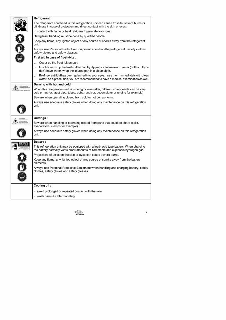
Refrigerant :
The refrigerant contained in this refrigeration unit can cause frosbite, severe burns orblindness in case of projection and direct contact with the skin or eyes.
In contact with flame or heat refrigerant generate toxic gas.
Refrigerant handling must be done by qualified people.
Keep any flame, any lighted object or any source of sparks away from the refrigerantunit.
Always use Personal Protective Equipment when handling refrigerant : safety clothes,safety gloves and safety glasses.
First aid in case of frost--bite :
a. Cover up the frost--bitten part.
b. Quickly warm up the frost--bitten part by dipping it into lukewarmwater (not hot). If youdon’t have water, wrap the injured part in a clean cloth.
c. If refrigerant fluid has been splashed into your eyes, rinse them immediately withcleanwater. As a precaution, you are recommended to have amedical examination as well.
Burning with hot and cold :
When this refrigeration unit is running or even after, different components can be verycold or hot (exhaust pipe, tubes, coils, receiver, accumulator or engine for example)
Beware when operating closed from cold or hot components.
Always use adequate safety gloves when doing any maintenance on this refrigerationunit.
Cuttings :
Beware when handling or operating closed from parts that could be sharp (coils,evaporators, clamps for example).
Always use adequate safety gloves when doing any maintenance on this refrigerationunit.
Battery :
This refrigeration unit may be equipped with a lead--acid type battery. When chargingthe battery normally vents small amounts of flammable and explosive hydrogen gas.
Projections of acids on the skin or eyes can cause severe burns.
Keep any flame, any lighted object or any source of sparks away from the batteryelements.
Always use Personal Protective Equipment when handling and charging battery: safetyclothes, safety gloves and safety glasses.
Cooling oil :
- avoid prolonged or repeated contact with the skin.
- wash carefully after handling.
8
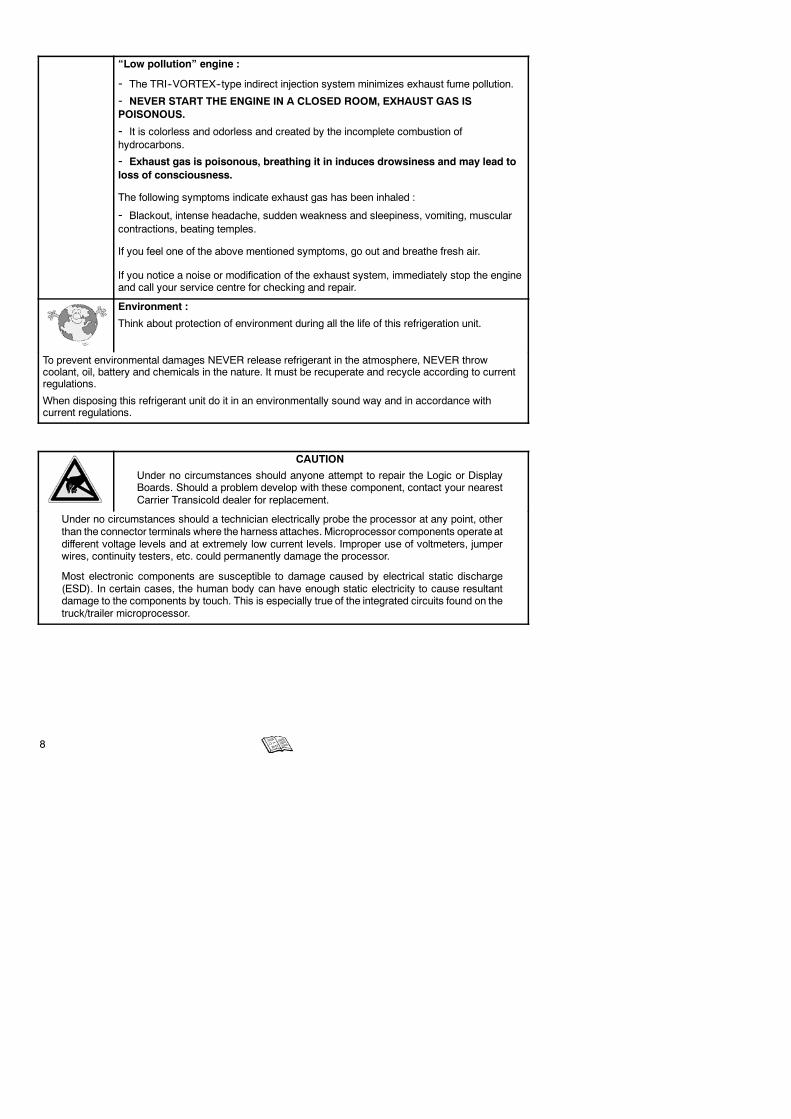
“Low pollution” engine :
- The TRI--VORTEX--type indirect injection system minimizes exhaust fume pollution.
- NEVER START THE ENGINE IN A CLOSED ROOM, EXHAUST GAS ISPOISONOUS.
- It is colorless and odorless and created by the incomplete combustion ofhydrocarbons.
- Exhaust gas is poisonous, breathing it in induces drowsiness and may lead toloss of consciousness.
The following symptoms indicate exhaust gas has been inhaled :
- Blackout, intense headache, sudden weakness and sleepiness, vomiting, muscularcontractions, beating temples.
If you feel one of the above mentioned symptoms, go out and breathe fresh air.
If you notice a noise or modification of the exhaust system, immediately stop the engineand call your service centre for checking and repair.
Environment :
Think about protection of environment during all the life of this refrigeration unit.
To prevent environmental damages NEVER release refrigerant in the atmosphere, NEVER throwcoolant, oil, battery and chemicals in the nature. It must be recuperate and recycle according to currentregulations.
When disposing this refrigerant unit do it in an environmentally sound way and in accordance withcurrent regulations.
CAUTION
Under no circumstances should anyone attempt to repair the Logic or DisplayBoards. Should a problem develop with these component, contact your nearestCarrier Transicold dealer for replacement.
Under no circumstances should a technician electrically probe the processor at any point, otherthan the connector terminals where the harness attaches. Microprocessor components operate atdifferent voltage levels and at extremely low current levels. Improper use of voltmeters, jumperwires, continuity testers, etc. could permanently damage the processor.
Most electronic components are susceptible to damage caused by electrical static discharge(ESD). In certain cases, the human body can have enough static electricity to cause resultantdamage to the components by touch. This is especially true of the integrated circuits found on thetruck/trailer microprocessor.

9
4. PRODUCT LOADING
Proper air circulation in the trailer body, air that can move around and through the load, is a critical elementin maintaining product quality during transport. If air cannot circulate completely around the load, hot spots ortop--freeze can occur.
The use of pallets is highly recommended. Pallets, when loaded so air can flow freely through the pallets toreturn to the evaporator, help protect the product from heat passing through the floor of the truck. When usingpallets, it is important to refrain from stacking extra boxes on the floor at the rear of the truck, because this willcut off the airflow.
Product stacking is another important factor in protecting the product. Products that generate heat, fruits andvegetables for example, should be stacked so the air can flow through the product to remove the heat; thisis called “air stacking” the product. Products that do not create heat, meats and frozen products, should bestacked tightly in the center of the trailer. All products should be kept away from the sidewalls of the body, allo-wing air to flow between the body and the load; this prevents heat filtering through the walls from affecting theproduct.
It is important to check the temperature of the product being loaded to ensure that it is at the correcttemperature for transport. The refrigeration unit is designed to maintain the temperature of the product at thetemperature at which it was loaded; it was not designed to cool a warm product.
OPTIONS FOR INSULATED BODIES
D Mobile partition
The mobile partition must be placed at a minimum distance from the evaporator of :
- 1700 mm for auxiliary evaporator
- 2600 mm for host unit evaporator
D Ducting of evaporator air outlet
Ventilation ducts must never be covered.
SOME ADVICE
Before loading
D Pre--cool the inside of the insulated body by lowering the temperature for about 15 minutes.
D Evacuate the humidity existing inside the box by carrying out a manual defrost. This can only take placewhen enabled by the defrost thermostat (box temperature lower than 3_C during pulldown and 8_C duringheating).
D Evaporator fans are protected by safety grills. In the event of heavy duty use of the unit, ice can accumulateon the grills. It is therefore recommended to clean them regularly by means of a small brush. The operationMUST be done when the unit has been SHUT DOWN.
When loading
D To be carried out with the unit stopped.
D It is recommended to open doors as little as possible to avoid the intake of hot air and humidity.
D Select the temperature by means of the thermostat, according to the transported goods.
D Check the internal temperature of the goods being loaded (using a probe thermometer).
10
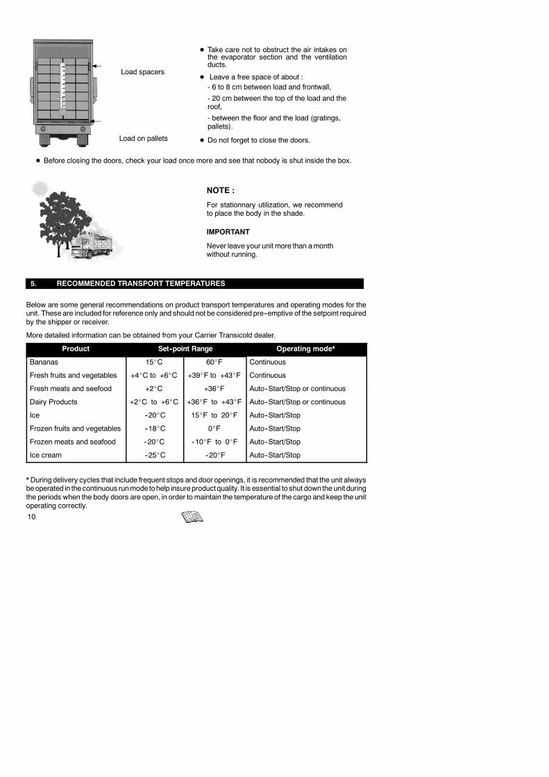
Load spacers
Load on pallets
D Take care not to obstruct the air intakes onthe evaporator section and the ventilationducts.
D Leave a free space of about :- 6 to 8 cm between load and frontwall,
- 20 cm between the top of the load and theroof,
- between the floor and the load (gratings,pallets).
D Do not forget to close the doors.
D Before closing the doors, check your load once more and see that nobody is shut inside the box.
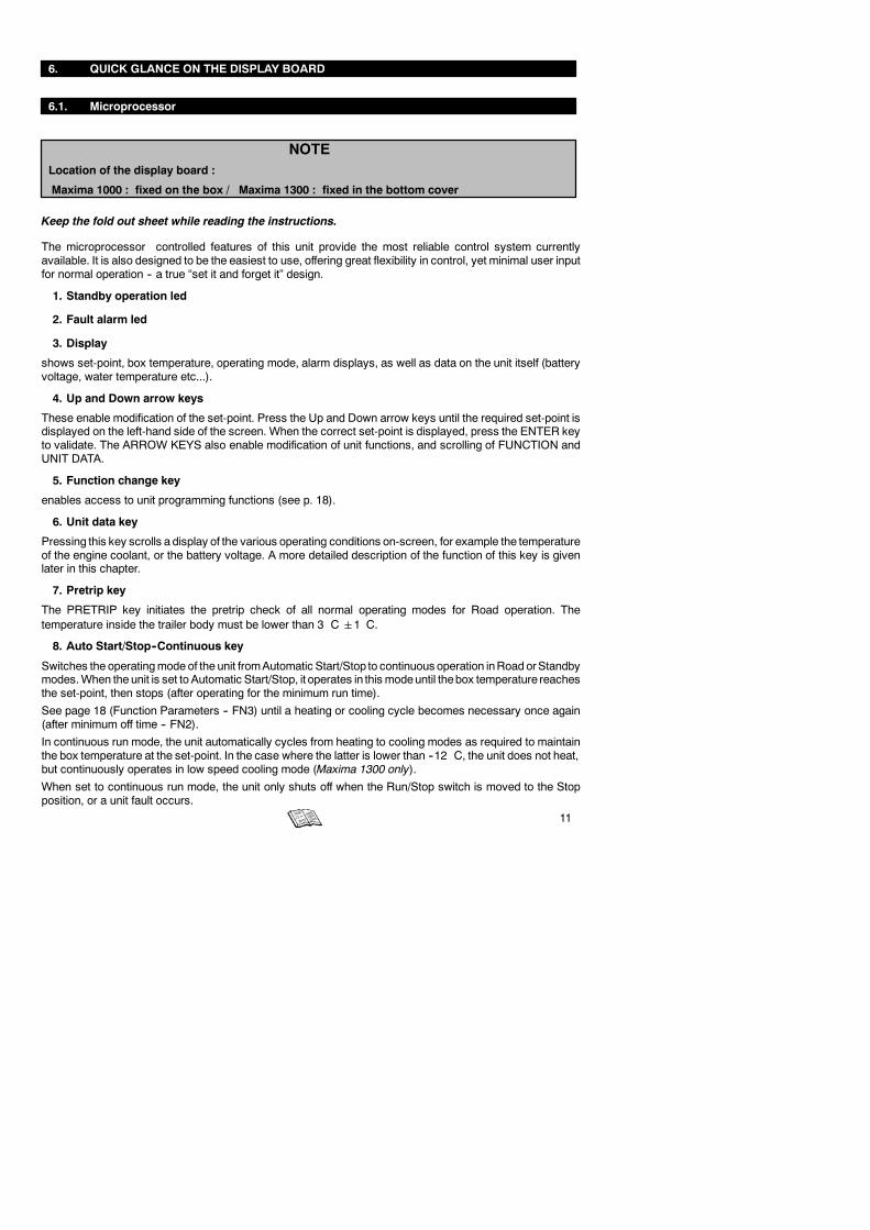
NOTE :
For stationnary utilization, we recommendto place the body in the shade.
IMPORTANT
Never leave your unit more than amonthwithout running.
5. RECOMMENDED TRANSPORT TEMPERATURES
Below are some general recommendations on product transport temperatures and operating modes for theunit. These are included for reference only and should not be considered pre--emptive of the setpoint requiredby the shipper or receiver.
More detailed information can be obtained from your Carrier Transicold dealer.
Product Set--point Range Operating mode*
Bananas 15_C 60_F Continuous
Fresh fruits and vegetables +4_C to +6_C +39_F to +43_F Continuous
Fresh meats and seefood +2_C +36_F Auto--Start/Stop or continuous
Dairy Products +2_C to +6_C +36_F to +43_F Auto--Start/Stop or continuous
Ice --20_C 15_F to 20_F Auto--Start/Stop
Frozen fruits and vegetables --18_C 0_F Auto--Start/Stop
Frozen meats and seafood --20_C --10_F to 0_F Auto--Start/Stop
Ice cream --25_C --20_F Auto--Start/Stop
* During delivery cycles that include frequent stops and door openings, it is recommended that the unit alwaysbeoperated in thecontinuous runmode tohelp insureproduct quality. It is essential to shut down the unit duringthe periods when the body doors are open, in order to maintain the temperature of the cargo and keep the unitoperating correctly.
11
6. QUICK GLANCE ON THE DISPLAY BOARD
6.1. Microprocessor
NOTELocation of the display board :
Maxima 1000 : fixed on the box / Maxima 1300 : fixed in the bottom cover
Keep the fold out sheet while reading the instructions.
The microprocessor controlled features of this unit provide the most reliable control system currentlyavailable. It is also designed to be the easiest to use, offering great flexibility in control, yet minimal user inputfor normal operation -- a true “set it and forget it” design.
1. Standby operation led
2. Fault alarm led
3. Display
shows set-point, box temperature, operating mode, alarm displays, as well as data on the unit itself (batteryvoltage, water temperature etc...).
4. Up and Down arrow keys
These enable modification of the set-point. Press the Up and Down arrow keys until the required set-point isdisplayed on the left-hand side of the screen. When the correct set-point is displayed, press the ENTER keyto validate. The ARROW KEYS also enable modification of unit functions, and scrolling of FUNCTION andUNIT DATA.
5. Function change key
enables access to unit programming functions (see p. 18).
6. Unit data key
Pressing this key scrolls a display of the various operating conditions on-screen, for example the temperatureof the engine coolant, or the battery voltage. A more detailed description of the function of this key is givenlater in this chapter.
7. Pretrip key
The PRETRIP key initiates the pretrip check of all normal operating modes for Road operation. Thetemperature inside the trailer body must be lower than 3�C1�C.
8. Auto Start/Stop--Continuous key
Switches the operatingmode of the unit fromAutomatic Start/Stop to continuous operation inRoad orStandbymodes.When the unit is set to Automatic Start/Stop, it operates in this modeuntil thebox temperature reachesthe set-point, then stops (after operating for the minimum run time).
See page 18 (Function Parameters -- FN3) until a heating or cooling cycle becomes necessary once again(after minimum off time -- FN2).
In continuous run mode, the unit automatically cycles from heating to cooling modes as required to maintainthe box temperature at the set-point. In the case where the latter is lower than --12�C, the unit does not heat,but continuously operates in low speed cooling mode (Maxima 1300 only).
When set to continuous run mode, the unit only shuts off when the Run/Stop switch is moved to the Stopposition, or a unit fault occurs.
12
9. Manual defrost key
TheMANUALDEFROST key switches the unit to defrost mode. It is not usually necessary to defrost the unitmanually, since it is fitted with a defrost timer and defrost air switch. Manual defrost may be necessary if iceaccumulates on the evaporator after frequency opening the trailer door in damp weather conditions (the DFmessage is displayed on-screen).
10. Enter key
This confirms changes entered concerning unit functions. The key enables validation of a change in set-pointmade using the Arrow-keys. If the Enter Key is not used, the set-point reverts to its previous value.
TheENTERkey alsoenables validationof achangemade to a function parameter. If theEnter Key is not used,the function reverts to its previous parameter.
11. Run/Stop switch
Controls unit operation. In the Run position, the unit starts up according to the operating mode previouslyspecified (Road or Standby).
12. Engine/Standby switch
When this switch is set to theENGINE position, the unit operates inDiesel mode (diesel engine) when the unitwas previously operating in Standby mode.
Important : If the screen display is blank, check the position of the RUN switch (11.) on the box.
7. OPERATION
Keep the fold out sheet while reading the instructions.
MAXIMA 1000 - MAXIMA 1300
The MAXIMA 1000/1300 are equipped with a diesel engine and an electric motor.
If necessary, the unit can operate as a heater simply by using the thermostat: its control is the same as forthe refrigeration cycle.
The START/STOP system automatically cycles the unit on and off during engine operation, regulatingrefrigeration or heating output to meet the temperature requirements of the products being transported.
D Diesel engine:
Diesel -- 4 cylinders -- water--cooled -- reinforced crankshaft bearings -- perfect balance at all speeds --low noise level -- water--oil safety switch -- large--volume oil pan.
D Electric motor :
230/400/3/50Hz
D 4--stage thermostat :
Four operating modes for temperature set--point > --12_C:
- High--speed cool
- Low--speed cool (Maxima 1300 only)
- Low--speed heat (Maxima 1300 only)

13
- High--speed heatTwo operating modes for temperature set--point < --12_C:
- High--speed cool
- Low--speed cool (Maxima 1300 only)
D Controller :
The unit is delivered fitted with a microprocessor controller.
D Charge alternator
- Maxima 1000/1300 : 14 VDC, 50 A
7.1. Operating principle
The operation of this self-contained unit is automatic.
7.1.1. In ROAD mode (engine operation)
With Start/Stop
The thermostat controls unit shut-down as soon as the set-point temperature has been reached.
Without Start/Stop
The diesel engine runs continuously. During temperature pulldown it runs at high speed. Down to --12_C, thebox temperature is regulated in low-speed (MAXIMA 1300only) cool and heat; under --12_C, a safety cut-outprevents any possibility of heating: this means that as soon as the set--point temperature has been reachedthe unit will run in low--speed cool.
NOTE: If a fixednegative temperatureselection is required lower than --12_C (e.g. --15_Cor --20_Cor --25_C),please contact your local Carrier dealer or service.
7.1.2. In STANDBY mode
With Start/Stop
The thermostat controls unit shut--down as soon as the set--point temperature has been reached.
Without Start/Stop
The unit will run continuously :
cool / heat for setpoint above --12_C
only cool for setpoint below --12_C
7.1.3. In DEFROST mode
The unit is equipped with an automatic defrost.
Triggering of the defrost cycle is controlled by a differential pressure air switch; shut--down of the defrost cycleis controlled by two defrost termination thermostats. The defrost cycle can also be controlledmanually.Duringthe defrost cycle the evaporator blower is off.
14
7.2. Petrip inspection
The pre--trip inspection should be performed before picking up any load. This inspection is essential toanticipate and help minimize the possibility of “on the road” problems. These checks take only a few minutes.
1. Place the unit’s main power switch to the Stop position.
2. Fuel -- Drain any water and impurities from the sump of the refrigeration unit fuel tank by opening thedrain--cock located on the bottom of the tank. Close the valve when only pure fuel emerges. Check thefuel level in the tank, ensuring that the fuel supply is adequate for unit operation. Refuel if necessary.
3. Belts -- Check the belt tension by depressing the belt with your thumb, near the center of the longestfree run of each belt. Under moderate pressure each belt should deflect approximately 6 mm to 13mm(1/4 inch to 1/2 inch). If the belts deflect more than this they should be tightened (loose belts may slip,generating heat and reducing belt life). If the belts are too tight they should be loosened; tight belts canreduce bearing life.
4. Battery -- On units equipped with serviceable batteries, the level of the electrolyte in each of the cellsshould be checked. If the level is low, distilled water should be added to the correct level. Most units,however, are equipped with low or maintenance--free batteries; these should be inspected to ensurethat the connections are clean and tight, and the battery hold--down should be checked for tightness.
1
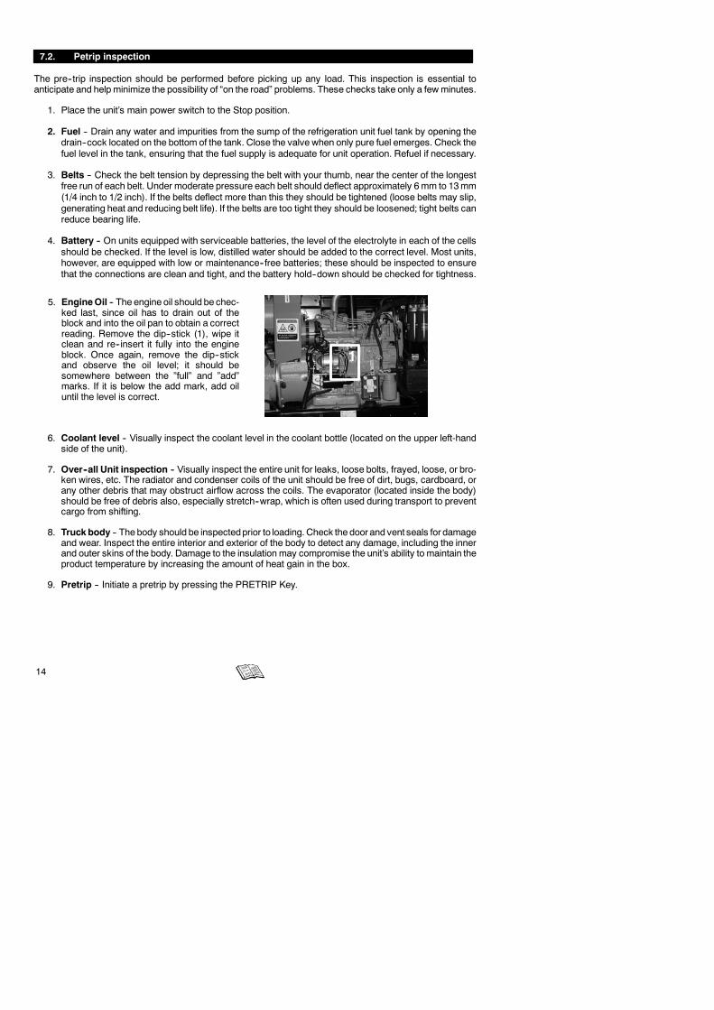
5. EngineOil -- The engine oil should be chec-ked last, since oil has to drain out of theblock and into the oil pan to obtain a correctreading. Remove the dip--stick (1), wipe itclean and re--insert it fully into the engineblock. Once again, remove the dip--stickand observe the oil level; it should besomewhere between the ”full” and ”add”marks. If it is below the add mark, add oiluntil the level is correct.
6. Coolant level -- Visually inspect the coolant level in the coolant bottle (located on the upper left-handside of the unit).
7. Over--all Unit inspection -- Visually inspect the entire unit for leaks, loose bolts, frayed, loose, or bro-ken wires, etc. The radiator and condenser coils of the unit should be free of dirt, bugs, cardboard, orany other debris that may obstruct airflow across the coils. The evaporator (located inside the body)should be free of debris also, especially stretch--wrap, which is often used during transport to preventcargo from shifting.
8. Truckbody -- The body should be inspectedprior to loading. Check the door and vent seals for damageand wear. Inspect the entire interior and exterior of the body to detect any damage, including the innerand outer skins of the body. Damage to the insulation may compromise the unit’s ability to maintain theproduct temperature by increasing the amount of heat gain in the box.
9. Pretrip -- Initiate a pretrip by pressing the PRETRIP Key.

15
7.3. Starting the unit -- Road operation
1. Complete the PRETRIP inspection described in the previous section.
2. If the unit was previously operating in STANDBY mode, place the switch (12.) to the ENGINE position.
3. Place the RUN/STOP switch (11.) to the RUN position.
NOTE
Under normal operating circumstances, this is all that is required to start the unit.
The microprocessor initiates a unit pretrip check, initiates preheating for a period determined by thetemperature of the engine coolant, and automatically starts the unit.
7.4. Starting the unit -- Standby operation
1. Check that the unit is connected to a suitable electricity supply (See section 7.4.1.)
2. Place the Standby switch (12.) to STANDBY.
3. Place the RUN/STOP switch (11.) to the RUN position.
NOTE
THE UNIT NOW OPERATES ON STANDBY. SEE THE TABLE ON PAGE 15 FOR INFORMATIONABOUT THE APPROPRIATE WIRING.
7.4.1. Standby operation guidelines
For safe, reliable operation in Standby mode, it is important to consider the following guidelines :
a. NEVER plug the unit in to the power source with the main switch inthe RUN position. The main switch should always be in the STOPposition when connecting the unit to the power source.
b. The extension cable and fuse used for network connection mustcomply with the legislation currently applicable on the site of use(minimum H07 RNF CEI 245--4) and with the unit specifications asdescribed in the table below :
aM 350/415 / 3/Standardized extension
UnitaM 350/415 / 3/
50 Hz
Standardized extensioncable H.07.RNFUnit 50 Hz
230 volts 400 volts
MAXIMA 1000/1300 30 A 10 mm2 6 mm2
aM : Motor rated fuse

16
c. The unit connection cable must be fittedwith a ground connection. The cablemust be connected to earth.
d. On the 400 V supply, the unitMUSTBE CONNECTED to a high sensibility (30mA) differential protection.
e. When performing service and/or maintenance procedures on a refrigeration unit, make certain that theunit is disconnected from the power source and that the keypad correctly indicates “OFF”, and that it isimpossible for the unit to start up automatically during the maintenance operation.
f. Operations on the 400 V supply for the unit must only be carried out by authorized personnel.
g. The user is liable for ensuring that the above measures are taken.
7.5. Unit shut--down
1. Place the RUN/STOP switch (11.) to STOP.
7.6. Changing the setpoint
1. Press the UP or DOWN arrow key (4.) until the desired setpoint is displayed.
2. Release the arrow key, then the setpoint will flash.
3. Press the ENTER key (10.) to confirm the new setpoint.
WARNING
IF THE ENTER KEY IS NOT PRESSED, THE SETPOINT WILL REVERT TO THE PREVIOUSLYENTERED SETPOINT.
7.7. Manuel defrost
1. Press MANUAL DEFROST key (9.).
NOTE
- THE BOX TEMPERATURE MUST BE EQUAL TO OR LOWER THAN +3_C.
- THE AUTOMATIC DEFROST CYCLE IS CONTROLLED BY AN AIR SWITCH OR BY A DEFROSTTIMER (PRESET 1,5 -- 3 -- 6 AND 12 HOURS) USING HOT GAS FROM THE COMPRESSOR.
- DURING THE DEFROST CYCLE, THE EVAPORATOR FAN IS STOPPED.
- DEFROST TERMINATION IS AUTOMATICALLY CONTROLLED BY TWO “KLIXON”THERMOSTATS.
- DURING DEFROST, DF IS DISPLAYED ON THE SCREEN.

17
7.8. To display unit data
The UNIT DATA key (6.) provides access to unit data listed below.
The unit data list can be scrolled through by pressing the UNIT DATA Key. The list will advance by one witheach key push; or press the UNIT DATA Key (6.) once and use the UP or DOWN ARROW keys (4.) to scrollthrough the list faster. Press the ENTER key (10.) to display the data for 30 seconds.
UNIT DATA
CODE ENGLISH DATA
CD1 SUCT Suction pressure
CD2 ENG Engine hours
CD3 WT Engine temperature
CD4 RAS Return air temperature
CD5 *SAS Supply air temperature
CD6 *REM Remote air temperature
CD7 ATS Ambient temperature
CD8 EVP Future expansion
CD9 CDT Not used
CD10 BATT Battery voltage
CD11 SBY Standby hours
CD12 MOD V Future expansion
CD13 REV Software revision
CD14 SERL Serial number low
CD15 SERU Serial number upper
CD16 2RA Future expansion
CD17 3RA Future expansion
CD18 MHR1 Maintenance hour meter 1
CD19 MHR2 Maintenance hour meter 2
CD20 SON Switch on hour meter
*SAS andREM are options. SAS is displayedwhen theSUPPROBEFunction is selected. REM is displayedwhen theREMPROBE Function is selected.

18
7.9. To change a function
The Function Settings below can be changed through the FUNCTION CHANGE key (5.).
WARNING
Before modifying any function, be aware of consequences.
Read carefully function parameters here below.
1. Press the FUNCTION CHANGE key (5.) until the Function you want change appears on the Display.
2. Press the ENTER key (10.) to select the Function you want to change.
3. Press the UP or DOWN ARROW key (4.) until the Function Setting you want appears on the Display.
4. Press the ENTER key (10.) to validate new setting.
FUNCTION PARAMETERS
CODE ENGLISH AVAILABLE SELECTIONS
FN0 DEFR Defrost interval 1.5, 3, 6, or 12 hr
FN1 ON HIGH AIR High air flow
FN1OFF
NORM AIR Normal air flow
FN2 OFF T Minimum off-time 10,20, 30, 45 or 90 mn
FN3 ON T On-time 4 or 7 min.
FN4 A REM PROBE Controlling Probe-Return air
FN4 B SUP PROBE Controlling Probe-Supply air (above12_C) (SAS)
FN5 Degrees _Cor _F
Temperature Unit (_C or _F)
FN6 ON TIME STRT Maximum Off-time 30 min.
FN6OFF
TEMP STRT Temperature based restarting (after minimum Off time)
FN7 0 MOP STD
FN7 -5 MOP -- Mop selection
FN7 +4 MOP +
p
FN8 2SET Set-point adjustment 2nd compartment -- YES / NO
FN9 3SET Set-point adjustment 3rd compartment -- YES / NO
FN10ON
AUTO OP Auto Start operation
FN10OFF
MAN OP Manual Start operation
FN11 T RANGE Out-of-Range 2, 3, or 4_C
19
FUNCTION PARAMETERS
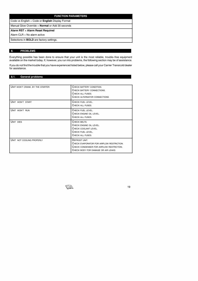
Code vs English = Code or English Display Format
Manual Glow Override = Normal or Add 30 seconds
Alarm RST = Alarm Reset Required
Alarm CLR = No alarm active
Selections in BOLD are factory settings.
8. PROBLEMS
Everything possible has been done to ensure that your unit is the most reliable, trouble--free equipmentavailable on themarket today. If, however, you run into problems, the following section may be of assistance.
If you do not find the trouble that you have experienced listed below, please call your Carrier Transicold dealerfor assistance.
8.1. General problems
UNIT WON’T CRANK, BY THE STARTER CHECK BATTERY CONDITION.
CHECK BATTERY CONNECTIONS.
CHECK ALL FUSES.
CHECK ALTERNATOR CONNECTIONS
UNIT WON’T START CHECK FUEL LEVEL.
CHECK ALL FUSES.
UNIT WON’T RUN CHECK FUEL LEVEL.
CHECK ENGINE OIL LEVEL.
CHECK ALL FUSES.
UNIT DIES CHECK BELTS.
CHECK ENGINE OIL LEVEL.
CHECK COOLANT LEVEL.
CHECK FUEL LEVEL.
CHECK ALL FUSES.
UNIT NOT COOLING PROPERLY DEFROST UNIT.
CHECK EVAPORATOR FOR AIRFLOW RESTRICTION.
CHECK CONDENSER FOR AIRFLOW RESTRICTION.
CHECK BODY FOR DAMAGE OR AIR LEAKS.

20
8.2. Fault alarm display and safety features
Display will alternate between an alarm message and the normal display whenever any of the failures listedbelow occur.
NOTE :Whenever the fault light is on, check display for fault message.1. Reset the micro to start the unit.
2. Press the FUNCTION CHANGE key (5.).
3. Press the UP or DOWN ARROW keys (4.) until ALARM RST is displayed.
4. Press ENTER key (10.) to clear alarm. ALARM CLR will now be displayed and unit will restart.
Other method to reset : move RUN/STOP switch (11.) to STOP. Unit resets and will start when RUN/STOPswitch (11.) is moved to run position.
ALARM DISPLAY √= FAULT LIGHT ONCODE ENGLISH DESCRIPTION
AL0 ENG OIL pLow Oil Pressure
AL1 ENG HOT pHigh Coolant Temperature
AL2 HI PRESS pHigh Pressure
AL3 STARTFAIL pAuto Start Failure
AL4 LOW BATT pLow Battery Voltage
AL5 HI BATT pHigh Battery Voltage
AL6 DEFRFAIL Defrost Override
AL7 ALT AUX pAlternator Auxiliary
AL8 STARTER pStarter Motor
AL9 RA SENSOR pReturn Air Sensor
AL10 SA SENSOR Supply Air Sensor
AL11 WT SENSOR Coolant Temperature Sensor
AL12 HIGH CDT pHigh discharge temperature
AL13 CD SENSOR Discharge temperature sensor
AL14 SBY MOTOR Not used
AL15 FUSE BAD pFuse
AL17 DISPLAY Display
AL18 SERVICE 1 Maintenance Hour Meter 1
AL19 SERVICE 2 Maintenance Hour Meter 2
AL20 OUT RANGE pMain Compartment Out-of-range
AL21 2RA OUT Not used
AL22 3RA OUT Not used
AL23 SYSTEM CK pCheck refrigeration system
p = FAULT LIGHT ON
WARNING : AL0 (ENG OIL) could come up if alternator is badly connected.

21
8.3. Fuses location
Refer to the fold out sheet for fuses location.
Maxima 1000 (from SN RB403109 -- 02/04) & 1300
FUSE IDENTIFICATION
Rep. Item Amps Rep. Item Amps
F1 Main fuse 60 A F8 Microprocessor fuse 5 A
F2 Solenoid / Water pump fuse 7.5 A F12 Fuel heater fuse (option) 25 A
F3 Electric fan clutch / Bypassvalve
25 A F13 Standby L1 25 A
F4 Hot gas fuse 15 A F14 Standby L2 25 A
F5 Speed control solenoid fuse 15 A F15 Standby L3 25 A
F6 Light bar (option) fuseAuto restart lightOut of ranger light
7.5 A FBTY Battery
150 A
9. MAINTENANCE
A comprehensive maintenance program will help to insure that the unit continues to operate reliably. Such amaintenance program will also help to control operating costs, increase the unit’s working life, and improveperformance. Refer to the “Maintenance information” section in CD “Généralité” for description of services,recommended oils...
NOTE
All maintenance services must be done by a technician trained on Carrier products respectingall safety and quality standards of Carrier.
9.1. Maintenance schedule
MAXIMA 1000/1300 Required Service
Oil filter with Bypass (in standard) A A AB
AC
AB
A ABC
A
Hours 400 1500 3000 4500 6000 7500 9000 10500
22
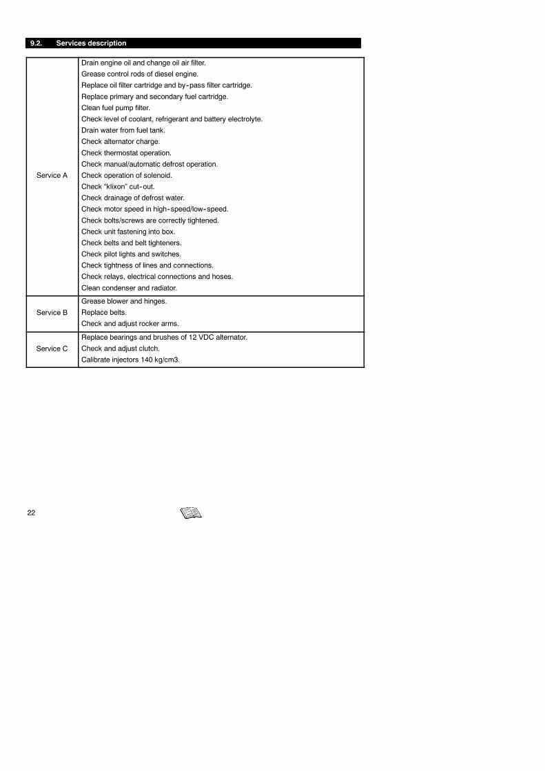
9.2. Services description
Service A
Drain engine oil and change oil air filter.
Grease control rods of diesel engine.
Replace oil filter cartridge and by--pass filter cartridge.
Replace primary and secondary fuel cartridge.
Clean fuel pump filter.
Check level of coolant, refrigerant and battery electrolyte.
Drain water from fuel tank.
Check alternator charge.
Check thermostat operation.
Check manual/automatic defrost operation.
Check operation of solenoid.
Check “klixon” cut--out.
Check drainage of defrost water.
Check motor speed in high--speed/low--speed.
Check bolts/screws are correctly tightened.
Check unit fastening into box.
Check belts and belt tighteners.
Check pilot lights and switches.
Check tightness of lines and connections.
Check relays, electrical connections and hoses.
Clean condenser and radiator.
Service B
Grease blower and hinges.
Replace belts.
Check and adjust rocker arms.
Service C
Replace bearings and brushes of 12 VDC alternator.
Check and adjust clutch.
Calibrate injectors 140 kg/cm3.

23
9.3. Recommended oil
Engine oil : The oils recommended for use in your refrigeration unit must comply with the AmericanPetroleumInstitute’s (API) SG/CD rating. The use of oil of the proper weight (viscosity) is also essential. The followingchart indicates the SAE Weight Rating of the oil to be used in various climates :
and over
10W or 10W30
20W or 15W40
30W or15W40
The following oils are accepted for use in Europe with the unit.
RECOMMENDED OILS
CARRIERAGIPANTARBP
ELF
FIATFINA
HAFA
IGOL
IMPERATOR
CARRIER TD+15W--40
SIGMA TURBO SHPD 15W--40
GRAPHITE R 15W--40
VANELLUS C3 EXTRA 15W--40
VANELLUS FE 15W30
MULTIPERFORMANCE4D 15W--40
PERFORMANCE TROPHY 15W--40
URANIA TURBO 15W--40
KAPPA LDO 15W--40
KAPPA TD PLUS 15W--40
KAPPA EXTRA 15W--40
DETERGENTE 4DM 15W--40
STRADEX 900 ECO 15W--40
SYNTHIDEX ECO 15W--40
RALLYE TURBO 4E 15W--40
RALLYE TURBO 4E LD 15W--40
RAFF SUPER HPDO 15W--40
LABOMOBIL
OPALORLYPOLAROILRENAULT
TEXACOTOTALSHELL
UNIL
YACCO
MEGAMAXI 15W--40
DELVAC SHC 15W--40
DELVAC 1400 SUPEROPALGET D 500 15W--40
TURBO 2002 15W--40
POLATRUCK 15W--40
KMX 2 PLUS 15W--30
KMX 2 PLUS 15W--40
MV5 “EUROPE”URSA SUPER TD 15W--40
RUBIA TIR MAX 15W40
MYRINA TX 15W--40
MYRINA T 15W--30
SUPER ROC 3D 15W--40
TURBO DX 15W--40
SM 4D + 15W--40

24
10. A.T.P. EUROPE REGULATION EXTRACT
(Date: March 1974)
Approval of vehicles intended for the carriage of perishable goods.
Before putting a refrigerated vehicle into service, it is necessary to have it approved by the Regional HealthDepartment.
CHARACTERISTICS OF VEHICLES USED FOR CARRYING PERISHABLE GOODS; REFRIGERATIONUNIT.
The refrigeration unit is an insulated unit with a cooling system which makes it possible, with a mean outsidetemperature of +30_C, to lower the temperature inside the empty body and to maintain this low temperaturein the following way:
CLASS A Refrigeration unit furnished with a cooling system whereby a temperature between+12_C and 0_C inclusive can be chosen.
CLASS B Refrigeration unit furnished with a cooling system whereby a temperature between+12_C and --10_C inclusive can be chosen.
CLASS C Refrigeration unit furnished with a cooling system whereby a temperature between+12_C and --20_C inclusive can be chosen.
The cooling capacity of a unit is determined by a test carried out in one of the approved testing stations andratified by an official report.
Note: The “K“ factor of bodies intended to be classified as C must be equal to or lower than 0.4 W/m2�C.
SIGNS, IDENTIFICATION MARKS AND PLATES TO BE ATTACHED TO REFRIGERATION UNITS
Refrigeration Plate : this reference must be followed by identification marks according to the following list:
Standard refrigeration unit Class A FNA
Reinforced refrigeration unit Class A FRA
Reinforced refrigeration unit Class B FRB
Reinforced refrigeration unit Class C FRC
Inaddition to theabove identificationmarks, thedate (monthand year) of expiry of theapproval certificatemustbe indicated.
Example :
FRC
6--2003
6 = month (June)
2003 = year
VERY IMPORTANT
Regularly check the expiry date of the approval certificate. During transport, the approval certificate orprovisional certificate should be shown on request of qualified agents. To have an insulated unit approved asa refrigeration unit, an application tomodify the approval certificate should be sent to the regional health office.

25
11. 24H ASSISTANCE
At Carrier Transicold we’re working hard to give you complete service when and where you need it. Thatimplies a worldwide network of dealers and available an emergency service. These service centers aremanned by factory--trained service personnel and backed by extensive parts inventories that will assure youof prompt repair.
Should you encounter a unit problem with your refrigeration unit during transit, follow your company’semergency procedure or contact the nearest Carrier Transicold service center. Consult the directory to locatethe service center nearest you. This directory may be obtained from your Carrier Transicold dealer.
If you are unable to reach a service center, call Carrier Transicold’s 24 Hour Assistance :
In Europe, please use the following free phone numbers from :
A AUSTRIA 0800 291039B BELGIUM 0800 99310CH SWITZERLAND 0800 838839D GERMANY 0800 1808180DK DENMARK 808 81832E SPAIN 900 993213F FRANCE 0800 913148FIN FINLAND 0800 113221GB GREAT BRITAIN 0800 9179067GR GREECE 00800 3222523H HUNGARY 06800 13526I ITALY 800 791033
IRL IRELAND 1800 553286L LUXEMBURG 800 3581
RUS RUSSIA 810 800 200 31032N NORWAY 800 11435NL THE NETHERLANDS 0800 0224894P PORTUGAL 8008 32283PL POLAND 00800 3211238S SWEDEN 020 790470
From other countries or direct : +32 9 255 67 89
In Canada or United States, call 1 -- 800 -- 448 -- 1661.
When calling, please have the following information ready for fastest service :
- Your name, the name of your company, and your location.
- A telephone number where you can be called back.
- Refrigeration unit model number and serial number.
- Box temperature, set--point and product.
- Brief description of the problem you are having, and what you have already done to correct theproblem.
We will do everything we can to get your problem taken care of and get you back on the road.

26