Operating Instructions - ecom
43
Operating Instructions
Transcript of Operating Instructions - ecom
Operating Instructions
Page 2 ecom-B
Index Page Important Hints 4 1. Instrument Design 6 2. Switch on Instrument 7 3. Choose a storage location 8 4. Gas Analysis 4.1. Measurement Preparations 9 4.2. Gas Analysis 9 4.3. Draft Measurement 11 4.4. Soot...Oil trace 12 4.5. Record and print Measurement Result 12 4.6. After Measurement 13 5. Mean value (option) 14 6. Measurement Routines (option) 6.1. Atmospheric Boilers 15 6.2. Fan Burners 6.2.1. Gas Fan Burners 19 6.2.2. Oil Fan Burners 22 6.3. Diagnosis gas 24 7. Pressure Tests (option) 26 8. Adjustment 33 9. Control 36 10. Data processing 10.1. Communication 37 10.2. Data processing with App 38 11. Maintenance Tips 39 12. Technical Data 41 13. FAQ 42

ecom-B Page 3
___________________________
Congratulations! With your purchase you have decided on a high-quality product of ecom GmbH. Get to know the product before you start using it while reading care-fully the following instructions of use and the safety indications. Use the product only as described and only for the given areas of applica-tion in order to ascertain its longevity.
___________________________
Page 4 ecom-B
Important Hints
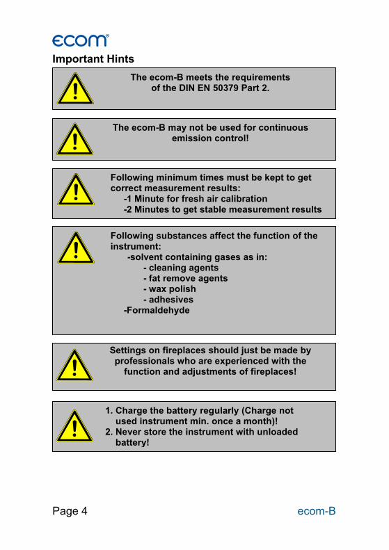
The ecom-B meets the requirements of the DIN EN 50379 Part 2.
The ecom-B may not be used for continuous emission control!
Following minimum times must be kept to get correct measurement results:
-1 Minute for fresh air calibration -2 Minutes to get stable measurement results
Following substances affect the function of the instrument:
-solvent containing gases as in: - cleaning agents - fat remove agents - wax polish - adhesives
-Formaldehyde
Settings on fireplaces should just be made by professionals who are experienced with the
function and adjustments of fireplaces!
1. Charge the battery regularly (Charge not used instrument min. once a month)! 2. Never store the instrument with unloaded battery!
ecom-B Page 5
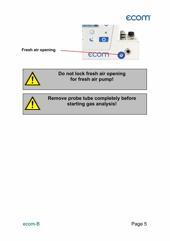
Do not lock fresh air opening for fresh air pump!
Fresh air opening
Remove probe tube completely before starting gas analysis!

Page 6 ecom-B
1. Instrument Design
Air temperature connection
ESC key (quit/
exit menu)
Gas temperature connection
RS232 interface
Gas connection
Draft connection
Pressure connection
Charging socket
Enter button (confirm
selection)
Cursor control (up/down/scroll)
Store key
Print key
Instrument ON/OFF CAL key
Standby key
Unlocking front flap
IR diode (for IR printer)
Condensate pad
ecom-B Page 7
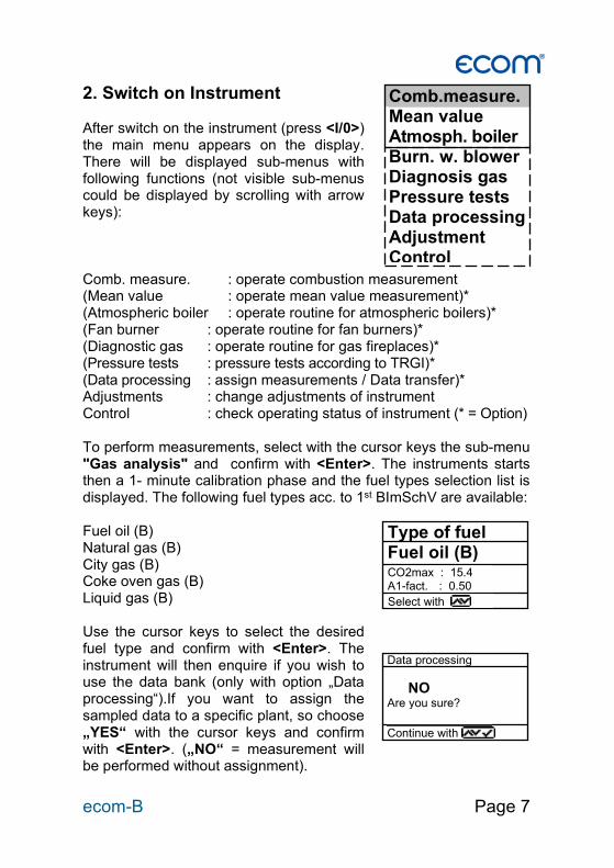
2. Switch on Instrument After switch on the instrument (press <I/0>) the main menu appears on the display. There will be displayed sub-menus with following functions (not visible sub-menus could be displayed by scrolling with arrow keys): Comb. measure. : operate combustion measurement (Mean value : operate mean value measurement)* (Atmospheric boiler : operate routine for atmospheric boilers)* (Fan burner : operate routine for fan burners)* (Diagnostic gas : operate routine for gas fireplaces)* (Pressure tests : pressure tests according to TRGI)* (Data processing : assign measurements / Data transfer)* Adjustments : change adjustments of instrument Control : check operating status of instrument (* = Option) To perform measurements, select with the cursor keys the sub-menu "Gas analysis" and confirm with <Enter>. The instruments starts then a 1- minute calibration phase and the fuel types selection list is displayed. The following fuel types acc. to 1st BImSchV are available: Fuel oil (B) Natural gas (B) City gas (B) Coke oven gas (B) Liquid gas (B) Use the cursor keys to select the desired fuel type and confirm with <Enter>. The instrument will then enquire if you wish to use the data bank (only with option „Data processing“).If you want to assign the sampled data to a specific plant, so choose „YES“ with the cursor keys and confirm with <Enter>. („NO“ = measurement will be performed without assignment).
Comb.measure. Mean value Atmosph. boiler Burn. w. blower Diagnosis gas Pressure tests Data processing Adjustment Control
Type of fuel Fuel oil (B) CO2max : 15.4 A1-fact. : 0.50
Select with
Data processing
NO Are you sure?
Continue with :
Page 8 ecom-B
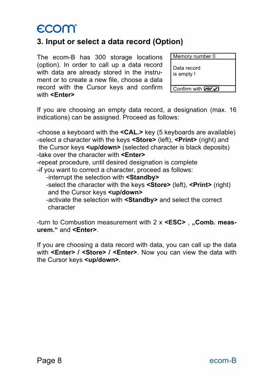
3. Input or select a data record (Option) The ecom-B has 300 storage locations (option). In order to call up a data record with data are already stored in the instru-ment or to create a new file, choose a data record with the Cursor keys and confirm with <Enter> If you are choosing an empty data record, a designation (max. 16 indications) can be assigned. Proceed as follows: -choose a keyboard with the <CAL.> key (5 keyboards are available) -select a character with the keys <Store> (left), <Print> (right) and the Cursor keys <up/down> (selected character is black deposits) -take over the character with <Enter> -repeat procedure, until desired designation is complete -if you want to correct a character, proceed as follows: -interrupt the selection with <Standby> -select the character with the keys <Store> (left), <Print> (right) and the Cursor keys <up/down> -activate the selection with <Standby> and select the correct character -turn to Combustion measurement with 2 x <ESC> , „Comb. meas-urem.“ and <Enter>. If you are choosing a data record with data, you can call up the data with <Enter> / <Store> / <Enter>. Now you can view the data with the Cursor keys <up/down>.
Memory number 0
Data record is empty !
Confirm with :
ecom-B Page 9
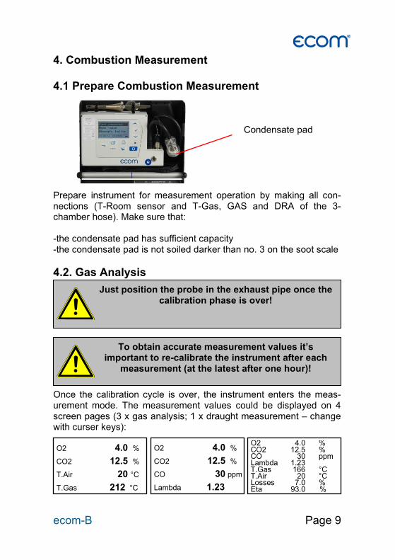
4. Combustion Measurement 4.1 Prepare Combustion Measurement Prepare instrument for measurement operation by making all con-nections (T-Room sensor and T-Gas, GAS and DRA of the 3-chamber hose). Make sure that: -the condensate pad has sufficient capacity -the condensate pad is not soiled darker than no. 3 on the soot scale
4.2. Gas Analysis Once the calibration cycle is over, the instrument enters the meas-urement mode. The measurement values could be displayed on 4 screen pages (3 x gas analysis; 1 x draught measurement – change with curser keys):
Just position the probe in the exhaust pipe once the calibration phase is over!
To obtain accurate measurement values it’s important to re-calibrate the instrument after each
measurement (at the latest after one hour)!
O2 4.0 % CO2 12.5 % CO 30 ppm Lambda 1.23 T.Gas 166 °C T.Air 20 °C Losses 7.0 % Eta 93.0 %
O2 4.0 %
CO2 12.5 %
T.Air 20 °C
T.Gas 212 °C
O2 4.0 %
CO2 12.5 %
CO 30 ppm Lambda 1.23
Condensate pad
Page 10 ecom-B
The position of the measured and calculated values (gas analysis) can be selected freely on the display. To change the position or the composition, please proceed as follows: -with <Enter> / <Display values> / <Enter> activate the first line on the display -choose with curser key the measured or calculated value -with <Enter> activate the next line on the display and so on -with <ESC> or <Enter> in the last line you leave this process. The values for CO
2, Efficiency, Losses, Lambda and the Dew Point
are calculated values. They just can be calculated when realistic figures for the basic values like O
2 and the temperature are available.
It must be assured that: O
2 < 20,5 % and T.Gas – T.Air > + 5°C
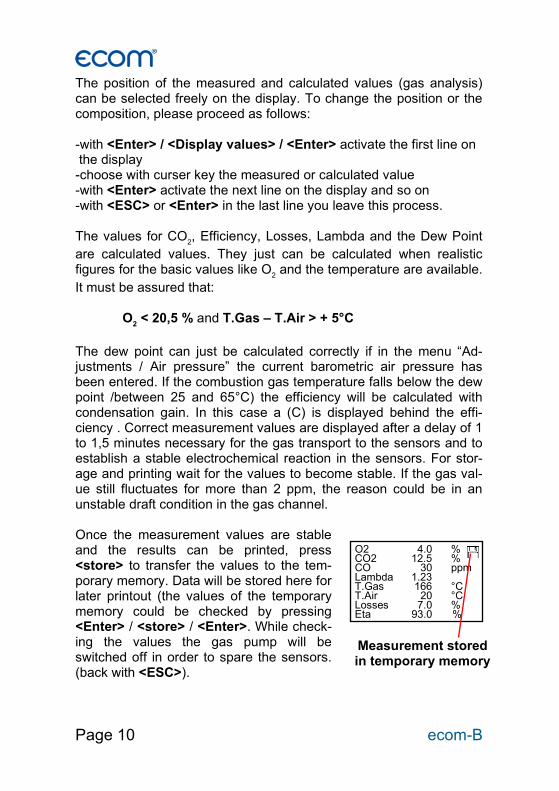
The dew point can just be calculated correctly if in the menu “Ad-justments / Air pressure” the current barometric air pressure has been entered. If the combustion gas temperature falls below the dew point /between 25 and 65°C) the efficiency will be calculated with condensation gain. In this case a (C) is displayed behind the effi-ciency . Correct measurement values are displayed after a delay of 1 to 1,5 minutes necessary for the gas transport to the sensors and to establish a stable electrochemical reaction in the sensors. For stor-age and printing wait for the values to become stable. If the gas val-ue still fluctuates for more than 2 ppm, the reason could be in an unstable draft condition in the gas channel. Once the measurement values are stable and the results can be printed, press <store> to transfer the values to the tem-porary memory. Data will be stored here for later printout (the values of the temporary memory could be checked by pressing <Enter> / <store> / <Enter>. While check-ing the values the gas pump will be switched off in order to spare the sensors. (back with <ESC>).
O2 4.0 % CO2 12.5 % CO 30 ppm Lambda 1.23 T.Gas 166 °C T.Air 20 °C Losses 7.0 % Eta 93.0 %
Measurement stored in temporary memory
ecom-B Page 11
CO-switch-off without purging pump The internal program protects the CO-sensor for overload. In case the limit of 2000 ppm (CO sensor without H2) is exceeded the gas pump will be switched off. Remove the probe off the combustion gas. Then press the key <CAL>. The gas pump turns on and purges the instrument with fresh air. After sufficient purge time the unit switches back to measuring mode (put the probe in the combustion gas). CO-switch-off with purging pump (option) The internal program protects the CO-sensor for overload. In case the limit of 4000 ppm (CO sensor with H2) is exceeded a second pump switches on and purges the sensor with fresh air. After suffi-cient purging time (blinking: "CO"), the sensor can be brought back to the measurement mode with <Enter> / <CO MV ON/OFF> / <En-ter> (the sensor can also manually be switched off by pressing <En-ter> / <CO MV ON/OFF> / <Enter>).
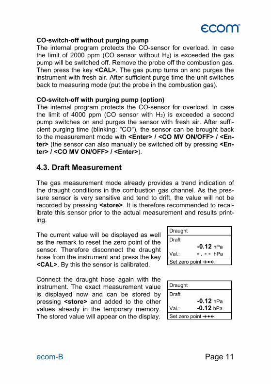
4.3. Draft Measurement The gas measurement mode already provides a trend indication of the draught conditions in the combustion gas channel. As the pres-sure sensor is very sensitive and tend to drift, the value will not be recorded by pressing <store>. It is therefore recommended to recal-ibrate this sensor prior to the actual measurement and results print-ing. The current value will be displayed as well as the remark to reset the zero point of the sensor. Therefore disconnect the draught hose from the instrument and press the key <CAL>. By this the sensor is calibrated. Connect the draught hose again with the instrument. The exact measurement value is displayed now and can be stored by pressing <store> and added to the other values already in the temporary memory. The stored value will appear on the display.
Draught Draft
-0.12 hPa
Val.: - . - - hPa
Set zero point CAL.
Draught Draft
-0.12 hPa
Val.: -0.12 hPa
Set zero point CAL.
Page 12 ecom-B
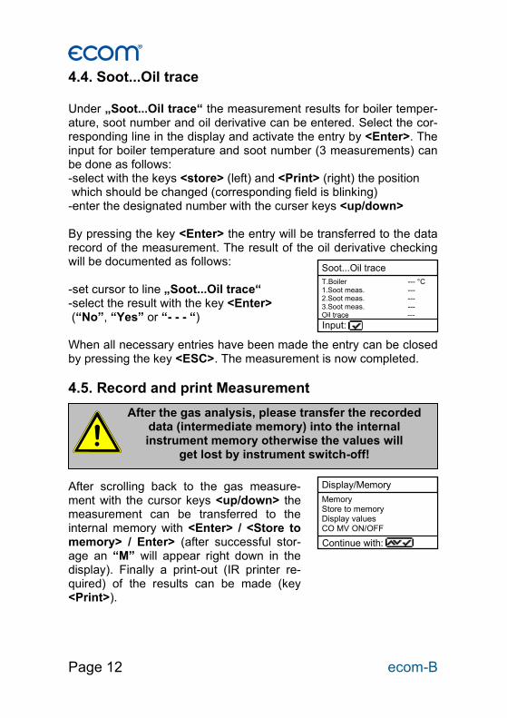
4.4. Soot...Oil trace Under „Soot...Oil trace“ the measurement results for boiler temper-ature, soot number and oil derivative can be entered. Select the cor-responding line in the display and activate the entry by <Enter>. The input for boiler temperature and soot number (3 measurements) can be done as follows: -select with the keys <store> (left) and <Print> (right) the position which should be changed (corresponding field is blinking) -enter the designated number with the curser keys <up/down> By pressing the key <Enter> the entry will be transferred to the data record of the measurement. The result of the oil derivative checking will be documented as follows: -set cursor to line „Soot...Oil trace“ -select the result with the key <Enter> (“No”, “Yes” or “- - - “) When all necessary entries have been made the entry can be closed by pressing the key <ESC>. The measurement is now completed.
4.5. Record and print Measurement After scrolling back to the gas measure-ment with the cursor keys <up/down> the measurement can be transferred to the internal memory with <Enter> / <Store to memory> / Enter> (after successful stor-age an “M” will appear right down in the display). Finally a print-out (IR printer re-quired) of the results can be made (key <Print>).
After the gas analysis, please transfer the recorded data (intermediate memory) into the internal instrument memory otherwise the values will
get lost by instrument switch-off!
Soot...Oil trace T.Boiler --- °C 1.Soot meas. --- 2.Soot meas. --- 3.Soot meas. --- Oil trace --- Input:
Display/Memory
Memory Store to memory Display values CO MV ON/OFF
Continue with:
ecom-B Page 13
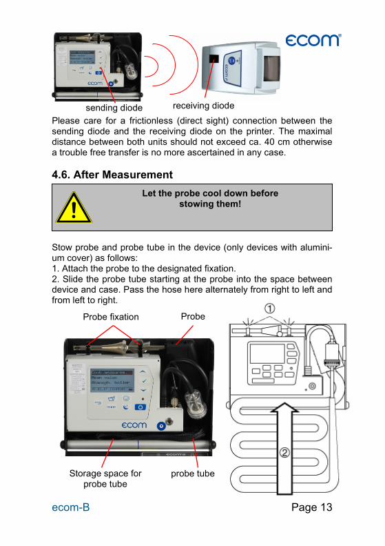
Please care for a frictionless (direct sight) connection between the sending diode and the receiving diode on the printer. The maximal distance between both units should not exceed ca. 40 cm otherwise a trouble free transfer is no more ascertained in any case.
4.6. After Measurement Stow probe and probe tube in the device (only devices with alumini-um cover) as follows: 1. Attach the probe to the designated fixation. 2. Slide the probe tube starting at the probe into the space between device and case. Pass the hose here alternately from right to left and from left to right.
Let the probe cool down before stowing them!
sending diode receiving diode
probe tube
Probe
Storage space for probe tube
Probe fixation
Page 14 ecom-B
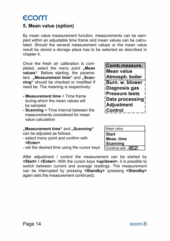
5. Mean value (option) By mean value measurement function, measurements can be sam-pled within an adjustable time frame and mean values can be calcu-lated. Should the several measurement values or the mean value result be stored a storage place has to be selected as described in chapter 4. Once the fresh air calibration is com-pleted, select the menu point „Mean values“. Before starting, the parame-ters „Measurement time“ and „Scan-ning“ should be checked or modified if need be. The meaning is respectively: - Measurement time = Time frame during which the mean values will be sampled - Scanning = Time interval between the measurements considered for mean value calculation „Measurement time“ and „Scanning“ can be adjusted as follows: - select menu point and confirm with <Enter> - set the desired time using the cursor keys After adjustment / control the measurement can be started by <Start> / <Enter>. With the cursor keys <up/down>, it is possible to switch between current and average readings. The measurement can be interrupted by pressing <Standby> (pressing <Standby> again sets the measurement continued).
Comb.measure. Mean value Atmosph. boiler Burn. w. blower Diagnosis gas Pressure tests Data processing Adjustment Control
Mean value Start Meas. time Scanning
Continue with :
ecom-B Page 15
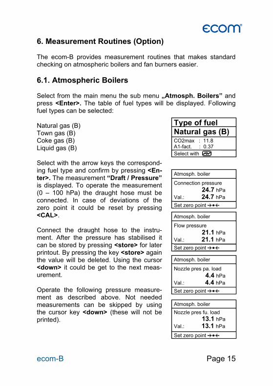
6. Measurement Routines (Option) The ecom-B provides measurement routines that makes standard checking on atmospheric boilers and fan burners easier.
6.1. Atmospheric Boilers Select from the main menu the sub menu „Atmosph. Boilers” and press <Enter>. The table of fuel types will be displayed. Following fuel types can be selected: Natural gas (B) Town gas (B) Coke gas (B) Liquid gas (B) Select with the arrow keys the correspond-ing fuel type and confirm by pressing <En-ter>. The measurement “Draft / Pressure” is displayed. To operate the measurement (0 – 100 hPa) the draught hose must be connected. In case of deviations of the zero point it could be reset by pressing <CAL>. Connect the draught hose to the instru-ment. After the pressure has stabilised it can be stored by pressing <store> for later printout. By pressing the key <store> again the value will be deleted. Using the cursor <down> it could be get to the next meas-urement. Operate the following pressure measure-ment as described above. Not needed measurements can be skipped by using the cursor key <down> (these will not be printed).
Type of fuel Natural gas (B) CO2max : 11.8 A1-fact. : 0.37
Select with
Atmosph. boiler Connection pressure
24.7 hPa
Val.: 24.7 hPa
Set zero point CAL.
Atmosph. boiler Flow pressure
21.1 hPa
Val.: 21.1 hPa
Set zero point CAL.
Atmosph. boiler Nozzle pres pa. load
4.4 hPa
Val.: 4.4 hPa
Set zero point CAL.
Atmosph. boiler Nozzle pres fu. load 13.1 hPa
Val.: 13.1 hPa
Set zero point CAL.
Page 16 ecom-B
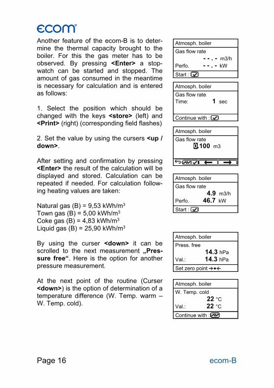
Another feature of the ecom-B is to deter-mine the thermal capacity brought to the boiler. For this the gas meter has to be observed. By pressing <Enter> a stop-watch can be started and stopped. The amount of gas consumed in the meantime is necessary for calculation and is entered as follows: 1. Select the position which should be changed with the keys <store> (left) and <Print> (right) (corresponding field flashes) 2. Set the value by using the cursers <up / down>. After setting and confirmation by pressing <Enter> the result of the calculation will be displayed and stored. Calculation can be repeated if needed. For calculation follow-ing heating values are taken: Natural gas (B) = 9,53 kWh/m3 Town gas (B) = 5,00 kWh/m3 Coke gas (B) = 4,83 kWh/m3 Liquid gas (B) = 25,90 kWh/m3 By using the curser <down> it can be scrolled to the next measurement „Pres-sure free“. Here is the option for another pressure measurement. At the next point of the routine (Curser <down>) is the option of determination of a temperature difference (W. Temp. warm – W. Temp. cold).
Atmosph. boiler W. Temp. cold
22 °C
Val.: 22 °C
Continue with :
Atmosph. boiler Press. free
14.3 hPa
Val.: 14.3 hPa
Set zero point CAL.
Atmosph. boiler Gas flow rate
- - . - m3/h
Perfo. - - . - kW
Start :
Atmosph. boiler Gas flow rate Time: 1 sec
Continue with :
Atmosph. boiler Gas flow rate
4.9 m3/h
Perfo. 46.7 kW
Start :
Atmosph. boiler Gas flow rate 0.100 m3
ecom-B Page 17
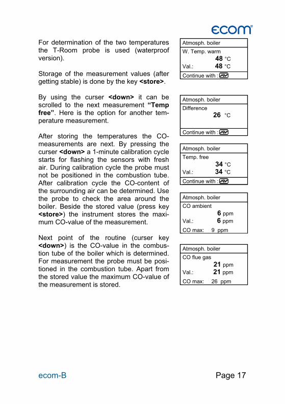
For determination of the two temperatures the T-Room probe is used (waterproof version). Storage of the measurement values (after getting stable) is done by the key <store>. By using the curser <down> it can be scrolled to the next measurement “Temp free”. Here is the option for another tem-perature measurement. After storing the temperatures the CO-measurements are next. By pressing the curser <down> a 1-minute calibration cycle starts for flashing the sensors with fresh air. During calibration cycle the probe must not be positioned in the combustion tube. After calibration cycle the CO-content of the surrounding air can be determined. Use the probe to check the area around the boiler. Beside the stored value (press key <store>) the instrument stores the maxi-mum CO-value of the measurement. Next point of the routine (curser key <down>) is the CO-value in the combus-tion tube of the boiler which is determined. For measurement the probe must be posi-tioned in the combustion tube. Apart from the stored value the maximum CO-value of the measurement is stored.
Atmosph. boiler CO ambient
6 ppm
Val.: 6 ppm
CO max: 9 ppm
Atmosph. boiler CO flue gas
21 ppm
Val.: 21 ppm
CO max: 26 ppm
Atmosph. boiler W. Temp. warm
48 °C
Val.: 48 °C
Continue with :
Atmosph. boiler Difference 26 °C
Continue with :
Atmosph. boiler Temp. free
34 °C
Val.: 34 °C
Continue with :

Page 18 ecom-B
After storing the CO-values the next point are the draught measurements (curser key <down>). For exact measuring it’s recom-mended to reset the sensor to zero. Re-move the draught hose off the instrument and press <CAL>. The zero point of the sensor is set now. After the draught has stabilised it can be stored for later printout by pressing the key <store>: At the end of the measurement routine (curser down) it is checked whether a gas leakage at the unit could be determined. Confirmation could be done by using the key <Enter> (yes / no). The printout (IR printer required) of all re-sults of the measurement routine could be done by pressing <Print>.
Atmosph. boiler Draft
-0.04 hPa
Val.: -0.04 hPa
Set zero point CAL.
Atmosph. boiler Gas leakage No
Change:
ecom-B Page 19
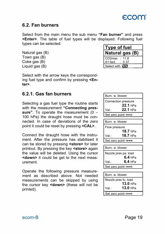
6.2. Fan burners Select from the main menu the sub menu “Fan burner” and press <Enter>. The table of fuel types will be displayed. Following fuel types can be selected: Natural gas (B) Town gas (B) Coke gas (B) Liquid gas (B) Select with the arrow keys the correspond-ing fuel type and confirm by pressing <En-ter>.
6.2.1. Gas fan burners Selecting a gas fuel type the routine starts with the measurement “Connecting pres-sure”. To operate the measurement (0 – 100 hPa) the draught hose must be con-nected. In case of deviations of the zero point it could be reset by pressing <CAL>. Connect the draught hose with the instru-ment. After the pressure has stabilised it can be stored by pressing <store> for later printout. By pressing the key <store> again the value will be deleted. Using the cursor <down> it could be get to the next meas-urement. Operate the following pressure measure-ment as described above. Not needed measurements can be skipped by using the cursor key <down> (these will not be printed).
Type of fuel Natural gas (B) CO2max : 11.8 A1-fact. : 0.37 Select with
Burn. w. blower Connection pressure
22.1 hPa
Val.: 22.1 hPa
Set zero point CAL.
Burn. w. blower Nozzle pres fu. load 13.0 hPa
Val.: 13.0 hPa
Set zero point CAL.
Burn. w. blower Nozzle pres pa. load
6.4 hPa
Val.: 6.4 hPa
Set zero point CAL.
Burn. w. blower Flow pressure
18.7 hPa
Val.: 18.7 hPa
Set zero point CAL.
Page 20 ecom-B
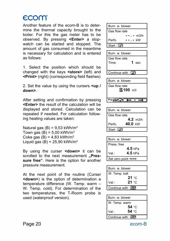
Another feature of the ecom-B is to deter-mine the thermal capacity brought to the boiler. For this the gas meter has to be observed. By pressing <Enter> a stop-watch can be started and stopped. The amount of gas consumed in the meantime is necessary for calculation and is entered as follows: 1. Select the position which should be changed with the keys <store> (left) and <Print> (right) (corresponding field flashes) 2. Set the value by using the cursers <up / down>. After setting and confirmation by pressing <Enter> the result of the calculation will be displayed and stored. Calculation can be repeated if needed. For calculation follow-ing heating values are taken: Natural gas (B) = 9,53 kWh/m3 Town gas (B) = 5,00 kWh/m3 Coke gas (B) = 4,83 kWh/m3 Liquid gas (B) = 25,90 kWh/m3 By using the curser <down> it can be scrolled to the next measurement „Pres-sure free“. Here is the option for another pressure measurement. At the next point of the routine (Curser <down>) is the option of determination a temperature difference (W. Temp. warm – W. Temp. cold). For determination of the two temperatures, the T-Room probe is used (waterproof version).
Burn. w. blower W. Temp. kalt
21 °C
Val.: 21 °C
Continue with :
Burn. w. blower W. Temp. warm
54 °C
Val.: 54 °C
Continue with :
Burn. w. blower Press. free
4.5 hPa
Val.: 4.5 hPa
Set zero point CAL.
Burn. w. blower Gas flow rate
- - . - m3/h
Perfo. - - . - kW
Start :
Burn. w. blower Gas flow rate Time: 1 sec
Continue with :
Burn. w. blower Gas flow rate
4.2 m3/h
Perfo. 40.0 kW
Start :
Burn. w. blower Gas flow rate 0.100 m3

ecom-B Page 21
Storage of the measurement values (after getting stable) is done with the key <store>. By using the curser <down> it can scrolled to the next measurement “Temp free”. Here is the option for another temperature measurement. After storing the temperatures the meas-urement of the combustion gases are next. By pressing the curser <down> a 1-minute calibration cycle starts for flashing the sen-sors with fresh air. During calibration cycle the probe must not be positioned in the combustion tube. After calibration cycle, the combustion measurement at part ca-pacity can be started. For measurement the probe must be positioned in the com-bustion tube. Measurement will be stated by pressing <Enter>. After 90 seconds the measured values will be automatically stored for later printout. Next point of the routine is the combustion measurement at full capacity by pressing <Enter>. Also here the values will be measured after 90 seconds. After finishing the combustion measure-ment the CO-value of the surrounding air can be determined. Use the probe to check the area around the boiler. Besides the stored value (press <store>) the instru-ment stores the maximum CO-value of the measurement.
Burn. w. blower CO ambient
5 ppm
Val.: 5 ppm
CO max: 9 ppm
Burn. w. blower Difference 33 °C
Continue with :
Burn. w. blower Temp. free
37 °C
Val.: 37 °C
Continue with :
CO2 9.6 % O2 4.0 % CO 30 ppm Eta 93.0 % T.Gas 166 °C T.Luft 20 °C
Parti. load Start :
CO2 9.6 % O2 4.0 % CO 30 ppm Eta 93.0 % T.Gas 166 °C T.Luft 20 °C
Full load Start :
Page 22 ecom-B
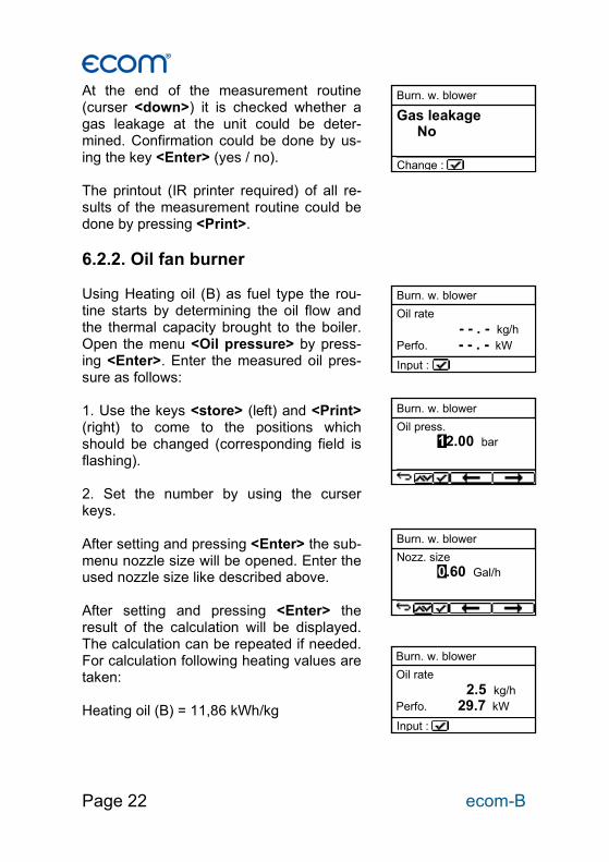
At the end of the measurement routine (curser <down>) it is checked whether a gas leakage at the unit could be deter-mined. Confirmation could be done by us-ing the key <Enter> (yes / no). The printout (IR printer required) of all re-sults of the measurement routine could be done by pressing <Print>.
6.2.2. Oil fan burner Using Heating oil (B) as fuel type the rou-tine starts by determining the oil flow and the thermal capacity brought to the boiler. Open the menu <Oil pressure> by press-ing <Enter>. Enter the measured oil pres-sure as follows: 1. Use the keys <store> (left) and <Print> (right) to come to the positions which should be changed (corresponding field is flashing). 2. Set the number by using the curser keys. After setting and pressing <Enter> the sub-menu nozzle size will be opened. Enter the used nozzle size like described above. After setting and pressing <Enter> the result of the calculation will be displayed. The calculation can be repeated if needed. For calculation following heating values are taken: Heating oil (B) = 11,86 kWh/kg
Burn. w. blower Gas leakage No
Change :
Burn. w. blower Oil rate
- - . - kg/h
Perfo. - - . - kW
Input :
Burn. w. blower Oil rate
2.5 kg/h
Perfo. 29.7 kW
Input :
Burn. w. blower Oil press. 12.00 bar
Burn. w. blower Nozz. size 0.60 Gal/h
ecom-B Page 23
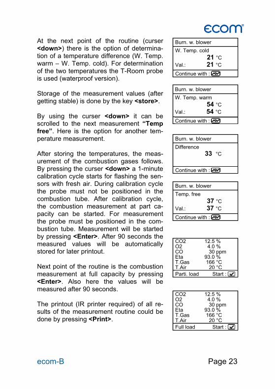
At the next point of the routine (curser <down>) there is the option of determina-tion of a temperature difference (W. Temp. warm – W. Temp. cold). For determination of the two temperatures the T-Room probe is used (waterproof version). Storage of the measurement values (after getting stable) is done by the key <store>. By using the curser <down> it can be scrolled to the next measurement “Temp free”. Here is the option for another tem-perature measurement. After storing the temperatures, the meas-urement of the combustion gases follows. By pressing the curser <down> a 1-minute calibration cycle starts for flashing the sen-sors with fresh air. During calibration cycle the probe must not be positioned in the combustion tube. After calibration cycle, the combustion measurement at part ca-pacity can be started. For measurement the probe must be positioned in the com-bustion tube. Measurement will be started by pressing <Enter>. After 90 seconds the measured values will be automatically stored for later printout. Next point of the routine is the combustion measurement at full capacity by pressing <Enter>. Also here the values will be measured after 90 seconds. The printout (IR printer required) of all re-sults of the measurement routine could be done by pressing <Print>.
Burn. w. blower W. Temp. cold
21 °C
Val.: 21 °C
Continue with :
Burn. w. blower W. Temp. warm
54 °C
Val.: 54 °C
Continue with :
Burn. w. blower Difference 33 °C
Continue with :
Burn. w. blower Temp. free
37 °C
Val.: 37 °C
Continue with :
CO2 12.5 % O2 4.0 % CO 30 ppm Eta 93.0 % T.Gas 166 °C T.Air 20 °C
Parti. load Start :
CO2 12.5 % O2 4.0 % CO 30 ppm Eta 93.0 % T.Gas 166 °C T.Air 20 °C
Full load Start :
Page 24 ecom-B
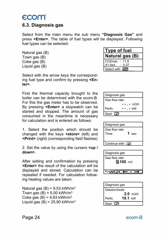
6.3. Diagnosis gas Select from the main menu the sub menu “Diagnosis Gas” and press <Enter>. The table of fuel types will be displayed. Following fuel types can be selected: Natural gas (B) Town gas (B) Coke gas (B) Liquid gas (B) Select with the arrow keys the correspond-ing fuel type and confirm by pressing <En-ter>. First the thermal capacity brought to the boiler can be determined with the ecom-B. For this the gas meter has to be observed. By pressing <Enter> a stopwatch can be started and stopped. The amount of gas consumed in the meantime is necessary for calculation and is entered as follows: 1. Select the position which should be changed with the keys <store> (left) and <Print> (right) (corresponding field flashes) 2. Set the value by using the cursers <up / down>. After setting and confirmation by pressing <Enter> the result of the calculation will be displayed and stored. Calculation can be repeated if needed. For calculation follow-ing heating values are taken: Natural gas (B) = 9,53 kWh/m3 Town gas (B) = 5,00 kWh/m3 Coke gas (B) = 4,83 kWh/m3 Liquid gas (B) = 25,90 kWh/m3
Type of fuel Natural gas (B) CO2max : 11.8 A1-fact. : 0.37 Select with
Diagnosis gas Gas flow rate
- - . - m3/h
Perfo. - - . - kW
Start :
Diagnosis gas Gasdurchsatz
2.0 m3/h
Perfo. 19.1 kW
Start :
Diagnosis gas Gas flow rate Time: 1 sec
Continue with :
Diagnosis gas Gas flow rate 0.100 m3
ecom-B Page 25
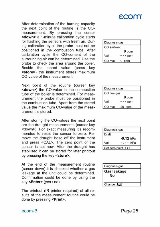
After determination of the burning capacity the next point of the routine is the CO-measurement. By pressing the curser <down> a 1-minute calibration cycle starts for flashing the sensors with fresh air. Dur-ing calibration cycle the probe must not be positioned in the combustion tube. After calibration cycle the CO-content of the surrounding air can be determined. Use the probe to check the area around the boiler. Beside the stored value (press key <store>) the instrument stores maximum CO-value of the measurement. Next point of the routine (curser key <down>) the CO-value in the combustion tube of the boiler is determined. For meas-urement the probe must be positioned in the combustion tube. Apart from the stored value the maximum CO-value of the meas-urement is stored. After storing the CO-values the next point are the draught measurements (curser key <down>). For exact measuring it’s recom-mended to reset the sensor to zero. Re-move the draught hose off the instrument and press <CAL>. The zero point of the sensor is set now. After the draught has stabilised it can be stored for later printout by pressing the key <store>. At the end of the measurement routine (curser down) it is checked whether a gas leakage at the unit could be determined. Confirmation could be done by using the key <Enter> (yes / no). The printout (IR printer required) of all re-sults of the measurement routine could be done by pressing <Print>.
Diagnosis gas
CO ambient
0 ppm
Val.: - - - ppm
CO max: 0 ppm
Diagnosis gas CO flue gas
0 ppm
Val.: - - - ppm
CO max: 26 ppm
Diagnosis gas Draft
-0.12 hPa
Val.: - . - - hPa
Set zero point CAL.
Diagnosis gas Gas leakage No
Change :
Page 26 ecom-B
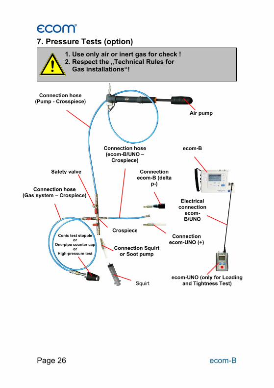
7. Pressure Tests (option)
1. Use only air or inert gas for check ! 2. Respect the „Technical Rules for Gas installations“!
Air pump
Connection hose (Pump - Crosspiece)
Safety valve
Crospiece
ecom-B
Connection hose (Gas system – Crospiece)
ecom-UNO (only for Loading and Tightness Test)
Squirt
Connection Squirt or Soot pump
Connection ecom-UNO (+)
Connection ecom-B (delta
p-)
Connection hose (ecom-B/UNO –
Crospiece)
Electrical connection
ecom-B/UNO
Conic test stopple or
One-pipe counter cap or
High-pressure test stopple
ecom-B Page 27
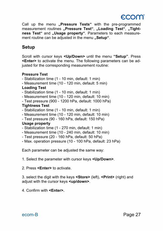
Call up the menu „Pressure Tests“ with the pre-programmed measurement routines „Pressure Test“, „Loading Test“, „Tight-ness Test“ and „Usage property“. Parameters to each measure-ment routine can be adjusted in the menu „Setup“.
Setup Scroll with cursor keys <Up/Down> until the menu “Setup”. Press <Enter> to activate the menu. The following parameters can be ad-justed for the corresponding measurement routine: Pressure Test - Stabilization time (1 - 10 min, default: 1 min) - Measurement time (10 - 120 min, default: 5 min) Loading Test - Stabilization time (1 - 10 min, default: 1 min) - Measurement time (10 - 120 min, default: 10 min) - Test pressure (900 - 1200 hPa, default: 1000 hPa) Tightness Test - Stabilization time (1 - 10 min, default: 1 min) - Measurement time (10 - 120 min, default: 10 min) - Test pressure (90 - 160 hPa, default: 150 hPa) Usage property - Stabilization time (1 - 270 min, default: 1 min) - Measurement time (10 - 240 min, default: 10 min) - Test pressure (20 - 160 hPa, default: 50 hPa) - Max. operation pressure (10 - 100 hPa, default: 23 hPa) Each parameter can be adjusted the same way: 1. Select the parameter with cursor keys <Up/Down>. 2. Press <Enter> to activate. 3. select the digit with the keys <Store> (left), <Print> (right) and adjust with the cursor keys <up/down>. 4. Confirm with <Enter>.

Page 28 ecom-B
Pressure Test The “Pressure Test” up to 100 hPa is deposited as a measurement routine in the ecom-B. Proceed as follows: 1. Close the conduit with a suitable adapter (test stopple, high-pressure stopple or one-pipe counter cap). 2. Connect the components as described before. 3. Scroll with cursor keys <Up/Down> to the menu “Pressure Test”. Activate with <Enter>. 4. Create the pre-adjusted test pressure (max. 100 hPa) with the air pump. 5. Interrupt the connection to the air pump (switch-off the ball valve) and start “Pressure Test” with <Enter>. 6. Wait for stabilization time (the measurement will start automatical-ly). 7. Once the measurement time is over, the result is displayed and can be printed (IR printer required) by pressing <Print>. 8. If the menu “Pressure Test” is selected again, so the result can be called up with “No” / <Enter> (as long as the ecom-B is on) or a new measurement can be started with “Yes” / <Enter> (switching from “No“ to “Yes“ with cursor keys <Up/Down>).

ecom-B Page 29
Loading Test The “Loading Test“ acc. to DVGW – TRGI Process Instructions G 600 at pipes (operation pressure up to 100 hPa) is deposited as a measurement routine in the ecom-B. Proceed as follows: 1. Connect the ecom-UNO to the connection AUX of the ecom-B. 2. Close the conduit with a suitable adapter (test stopple, high-pressure stopple or one-pipe counter cap). 3. Connect the components as described before. 4. Scroll with cursor keys <Up/Down> to the menu „Loading Test“. Activate with <Enter>. 5. Create the pre-adjusted test pressure with the air pump (the unit beeps as soon as the pressure level is achieved). 6. Interrupt the connection to the air pump (switch-off the ball valve). 7. Wait for stabilization time (if the pressure remains in the range “test pressure +/- 10%” during stabilization time, so the measure-ment will start). 8. Once the measurement time is over, the result is displayed and can be printed (IR printer required) by pressing <Print>. 9. If the menu “Loading Test“ is selected again, so the result can be called up with “No” / <Enter> (as long as the ecom-B is on) or a new measurement can be started with “Yes” / <Enter> (switching from “No“ to “Yes“ with cursor keys <Up/Down>).
Page 30 ecom-B
Tightness Test The “Tightness Test“ acc. to DVGW – TRGI Process Instructions G 600 at pipes (operation pressure up to 100 hPa) is deposited as a measurement routine in the ecom-B. Proceed as follows: 1. Connect the ecom-UNO to the connection AUX of the ecom-B. 2. Close the conduit with a suitable adapter (test stopple, high-pressure stopple or one-pipe counter cap). 3. Connect the components as described before. 4. Scroll with cursor keys <Up/Down> to the menu „Tightness Test“. Activate with <Enter>. 5. Create the pre-adjusted test pressure with the air pump (the unit beeps as soon as the pressure level is achieved). 6. Interrupt the connection to the air pump (switch-off the ball valve). 7. Wait for stabilization time (if the pressure remains in the range “test pressure +/- 10%” during stabilization time, so the measure-ment will start). 8. Once the measurement time is over, the result is displayed and can be printed (IR printer required) by pressing <Print>. 9. If the menu “Tightness Test“ is selected again, so the result can be called up with “No” / <Enter> (as long as the ecom-B is on) or a new measurement can be started with “Yes” / <Enter> (switching from “No“ to “Yes“ with cursor keys <Up/Down>).
ecom-B Page 31
Usage property The “Usage property“ acc. to DVGW – TRGI Process form G 624 at conduits is memorised as a measurement routine by the ecom-B. The calculation of the leak rate happens automatically according to the following equation and corresponds herewith to the procedure of the DVGW-TRGI Process Form G 624: VB = V/TM * ((PA + P1)/(PA + P2)-1) * PB/P1 * f with: VB = Gas leak volume in operation state (l/h) V = Pipe content in litres TM = Measurement duration in hours PA = Barometer stand in hPa P1 = Test pressure at meas. beginning in hPa P2 = Test pressure at measurement end in hPa PB = Maximal gas operation pressure in hPa f = Factor for consideration of gas type Proceed as follows: 1. Close the conduit with a suitable adapter (test stopple, high-pressure stopple or one-pipe counter cap). 2. Connect the components as described before. 3. Scroll with cursor keys <Up/Down> to the menu „Usage proper-ty“. Activate with <Enter>. 4. Adjust the air pressure (PA) with cursor keys <Up/Down> and confirm with <Enter>. 5. Choose the gas type (f) with cursor keys <Up/Down> and confirm with <Enter>. The following gas types are recorded with their re-spective factors: Natural Gas, Air, Town Gas, Propane, Butane, Hydrogen 6. Adjust the maximal operation pressure (PB) with cursor keys <Up/Down> and confirm with <Enter>.
Page 32 ecom-B
7. The pipe volume (V) is needed for the calculation of the leak rate. The ecom-B offers two possibilities: a. Type in pipe volume (V): - Choose “No” at the inquiry “Calculate Volume automatically ?“ (switching from “No“ to “Yes“ with cursor keys <Up/Down>). - Adjust pipe volume (V) with cursor keys <Up/Down> and confirm with <Enter>.
b. Calculate pipe volume automatically (V): - Choose YES at the inquiry „Calculate Volume automatically ?“. - Connect the squirt or soot pump as described before. - Open ball valve and wait until the pressure is stabilized. - Choose squirt or soot pump with the key <CAL.>. - Start volume calculation with <Enter>. - Infer the test volume with squirt or soot pump. The decrease of pressure must be min. 2 hPa (otherwise operate squirt or soot pump several times). - Close ball valve and confirm with <Enter>. - Choose number of strokes with cursor keys <Up/Down> and con-firm with <Enter>. 8. Create the pre-adjusted test pressure with the air pump (the unit beeps as soon as the pressure level is achieved). 9. Interrupt the connection to the air pump (switch-off the ball valve). 10. Wait for stabilization time (if the pressure remains in the range “test pressure +/- 10%” during stabilization time, so the measure-ment will start). 11. Once the measurement time is over, the result is displayed and can be printed (IR printer required) by pressing <Print>. 12. If the menu “Usage property“ is selected again, so the result can be called up with “No” / <Enter> (as long as the ecom-B is on) or a new measurement can be started with “Yes” / <Enter> (switch-ing from “No“ to “Yes“ with cursor keys <Up/Down>).
ecom-B Page 33
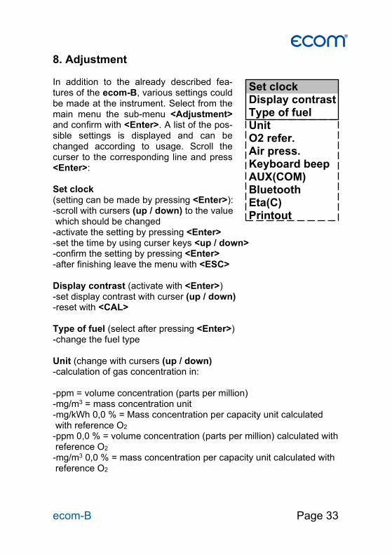
8. Adjustment In addition to the already described fea-tures of the ecom-B, various settings could be made at the instrument. Select from the main menu the sub-menu <Adjustment> and confirm with <Enter>. A list of the pos-sible settings is displayed and can be changed according to usage. Scroll the curser to the corresponding line and press <Enter>: Set clock (setting can be made by pressing <Enter>): -scroll with cursers (up / down) to the value which should be changed -activate the setting by pressing <Enter> -set the time by using curser keys <up / down> -confirm the setting by pressing <Enter> -after finishing leave the menu with <ESC> Display contrast (activate with <Enter>) -set display contrast with curser (up / down) -reset with <CAL> Type of fuel (select after pressing <Enter>) -change the fuel type Unit (change with cursers (up / down) -calculation of gas concentration in: -ppm = volume concentration (parts per million) -mg/m3 = mass concentration unit -mg/kWh 0,0 % = Mass concentration per capacity unit calculated with reference O2 -ppm 0,0 % = volume concentration (parts per million) calculated with reference O2 -mg/m3 0,0 % = mass concentration per capacity unit calculated with reference O2
Set clock Display contrast Type of fuel Unit O2 refer. Air press. Keyboard beep AUX(COM) Bluetooth Eta(C) Printout
Page 34 ecom-B
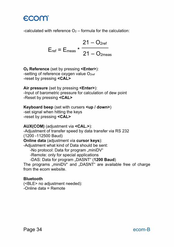
-calculated with reference O2 – formula for the calculation: O2 Reference (set by pressing <Enter>): -setting of reference oxygen value O2ref -reset by pressing <CAL> Air pressure (set by pressing <Enter>): -Input of barometric pressure for calculation of dew point -Reset by pressing <CAL> Keyboard beep (set with cursers <up / down>) -set signal when hitting the keys -reset by pressing <CAL> AUX(COM) (adjustment via <CAL.>): -Adjustment of transfer speed by data transfer via RS 232 (1200 -112500 Baud) Online data (adjustment via cursor keys): -Adjustment what kind of Data should be sent: -No protocol: Data for program „miniDV“ -Remote: only for special applications -DAS: Data for program „DASNT“ (1200 Baud) The programs „miniDV“ and „DASNT“ are available free of charge from the ecom website. Bluetooth (<BLE> no adjustment needed): -Online data = Remote
Eref = Emeas *
21 – O2ref
21 – O2meas
ecom-B Page 35
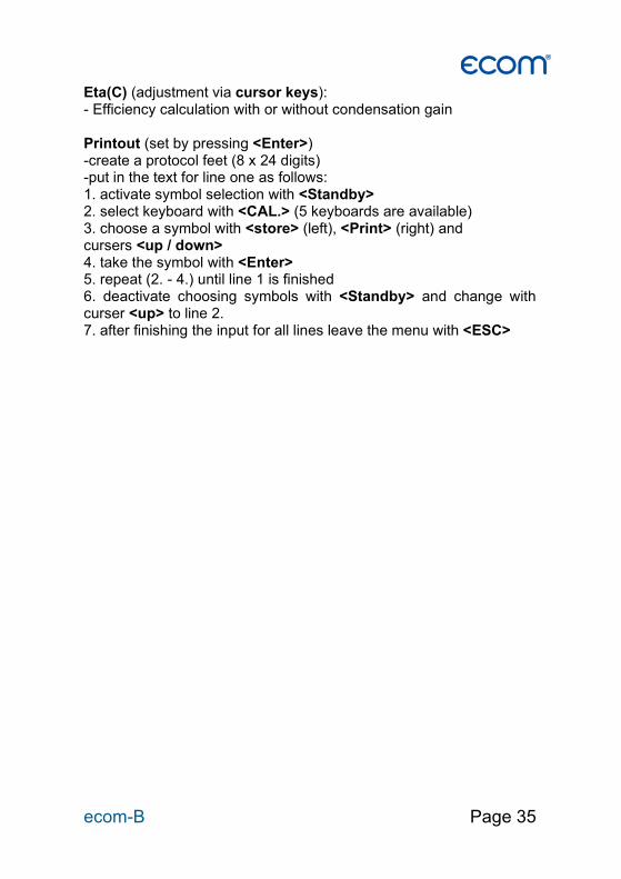
Eta(C) (adjustment via cursor keys): - Efficiency calculation with or without condensation gain Printout (set by pressing <Enter>) -create a protocol feet (8 x 24 digits) -put in the text for line one as follows: 1. activate symbol selection with <Standby> 2. select keyboard with <CAL.> (5 keyboards are available) 3. choose a symbol with <store> (left), <Print> (right) and cursers <up / down> 4. take the symbol with <Enter> 5. repeat (2. - 4.) until line 1 is finished 6. deactivate choosing symbols with <Standby> and change with curser <up> to line 2. 7. after finishing the input for all lines leave the menu with <ESC>
Page 36 ecom-B
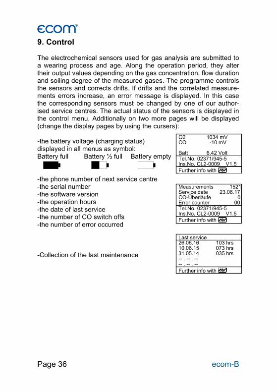
9. Control The electrochemical sensors used for gas analysis are submitted to a wearing process and age. Along the operation period, they alter their output values depending on the gas concentration, flow duration and soiling degree of the measured gases. The programme controls the sensors and corrects drifts. If drifts and the correlated measure-ments errors increase, an error message is displayed. In this case the corresponding sensors must be changed by one of our author-ised service centres. The actual status of the sensors is displayed in the control menu. Additionally on two more pages will be displayed (change the display pages by using the cursers): -the battery voltage (charging status) displayed in all menus as symbol: Battery full Battery ½ full Battery empty -the phone number of next service centre -the serial number -the software version -the operation hours -the date of last service -the number of CO switch offs -the number of error occurred -Collection of the last maintenance
O2 1034 mV CO -10 mV Batt 6.42 Volt Tel.No. 02371/945-5 Ins.No. CL2-0009 V1.5
Further info with
Measurements 1521 Service date 23.06.17 CO-Überläufe 0 Error counter 00 Tel.No. 02371/945-5 Ins.No. CL2-0009 V1.5
Further info with
Last service 26.06.16 103 hrs 10.06.15 073 hrs 31.05.14 035 hrs -- . -- . -- -- . -- . -- Further info with
ecom-B Page 37
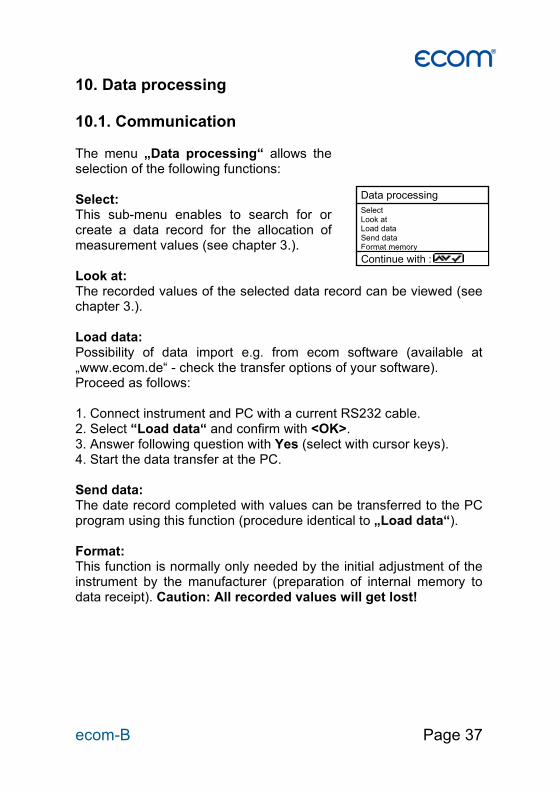
10. Data processing 10.1. Communication The menu „Data processing“ allows the selection of the following functions: Select: This sub-menu enables to search for or create a data record for the allocation of measurement values (see chapter 3.). Look at: The recorded values of the selected data record can be viewed (see chapter 3.). Load data: Possibility of data import e.g. from ecom software (available at „www.ecom.de“ - check the transfer options of your software). Proceed as follows: 1. Connect instrument and PC with a current RS232 cable. 2. Select “Load data“ and confirm with <OK>. 3. Answer following question with Yes (select with cursor keys). 4. Start the data transfer at the PC. Send data: The date record completed with values can be transferred to the PC program using this function (procedure identical to „Load data“). Format: This function is normally only needed by the initial adjustment of the instrument by the manufacturer (preparation of internal memory to data receipt). Caution: All recorded values will get lost!
Data processing Select Look at Load data Send data Format memory
Continue with :

Page 38 ecom-B
10.2. Data processing with App To display and storage of measured values, the App "ecomMAND-ER" for smartphones (iOS or Android) is available (Bluetooth LE needed). Test results are stored along with customer information in a pdf-file and can be sent f.e. as email attachment. Links to free down-load of the Apps can be found on the ecom website.
ecom-B Page 39
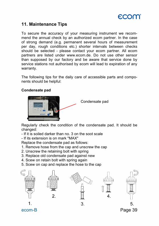
11. Maintenance Tips To secure the accuracy of your measuring instrument we recom-mend the annual check by an authorized ecom partner. In the case of strong demand (e.g. permanent several hours of measurement per day, rough conditions etc.) shorter intervals between checks should be selected - please contact your ecom partner. All ecom partners are listed under www.ecom.de. Do not use other sensor than supposed by our factory and be aware that service done by service stations not authorised by ecom will lead to expiration of any warranty. The following tips for the daily care of accessible parts and compo-nents should be helpful: Condensate pad Regularly check the condition of the condensate pad. It should be changed: - If it is soiled darker than no. 3 on the soot scale - If its extension is on mark "MAX" Replace the condensate pad as follows: 1. Remove hose from the cap and unscrew the cap 2. Unscrew the retaining bolt with spring 3. Replace old condensate pad against new 4. Scew on retain bolt with spring again 5. Scew on cap and replace the hose to the cap
Condensate pad

Page 40 ecom-B
Sensors Each time the instrument is switched on the sensors are calibrated with fresh air. The instrument permanently monitors the condition of the sensors. New sensors wear out from use in time due to reaction (O2-sensor) and due to soiled gases respectively gases in concen-trations beyond the nominal range (toxic sensors). The output values of the sensors are (see menu “Control”):
O2 approx. 1500 mV CO 0 mV (+/- 30)
If an error message is displayed during calibration cycle and does not disappear after repeated calibrations the instrument must be send to a service centre. The O2 sensor should show > 200 mV, otherwise it should be changed. The CO-sensor is protected by the internal program for overload. In case the limit of 4000 ppm is exceeded the gas pump is switched off. Power supply The battery ensures a main power independent operation. The bat-tery is automatically charged when the instrument is connected to the main power supply. (Please do not interrupt the charging shortly since the charging circuitry could operate faulty.) The recharge of the battery should be done in any case if the voltage display (menu “Control”) is less than 5.8 V (Instrument will stop working at 5.5 V). Sampling probe and hose Depending on the frequency of use the probe and the hose must be cleaned regularly, thus in order to prevent particles from lodging and early ware due to corrosion. The hose can be cleaned after all connections on the instrument and the probe itself have been switched off (use warm water and then blow out to dry)
ecom-B Page 41
12. Technical Data
Parameter Range Measurement principles O2 0 ... 21 vol.% electrochemical CO (without H2) 0 ... 2000 ppm electrochemical CO (with H2-option) 0 ...4000 ppm electrochemical NO (Option) 0 ...5000 ppm electrochemical CO2 0 ...CO2max calculated T-G 0 ... 500 °C NiCr-Ni T-R 0 ... 100 °C semiconductor Pressure 0 ... +/- 100 hPa DMS-bridge Efficiency 0 ... 120 % calculated Losses 0 ... 99,9 % calculated Lambda 1 ... calculated CO-undiluted (reference-O2; adjustable) calculated Dew point of combustion gases calculated Power Supply 110 - 230 V~ / 50 - 60 Hz; Battery 6 V / 3,3 Ah Display: graphic display, backlit Size (W x H x D) 250 mm x 180 mm x 80 mm Weight approx. 2,1 kg (complete with sampling system) Application limits +5 °C to +40 °C; max. 90 % RH, non-condensing
Subject to technical changes V1.8 / 11.2020
ecom GmbH
Am Großen Teich 2 D-58640 Iserlohn
Phone: +49 (0) 2371 - 945-5 Fax: +49 (0) 2371 - 40305
Internet: http://www.ecom.de eMail: [email protected]

Page 42 ecom-B
13. FAQ
Where do I find important instru-ment information? How long is the life span of the sensors? Which sensors can I exchange? The instrument shows the error message „O2 sensor 0 mV“! The instrument shows the mes-sage „Check required“! The instrument shows the error message „T-Gas“ or „T-Air“! The instrument shows wrong or inaccurately CO2 values!
In the menu „Control“ all important instrument infor-mation are shown (e.g. battery voltage, sensor val-ues, unit number, next service date, operation hours etc.). With the arrow keys stands you can switch to the second page. The life span depends on the operating hours and the instrument equipment. The life span of the toxic sensors (CO, NO, SO2, NO2) is affected by high gas concentrations and a not sufficient purging. The life span for these sensors amounts to on the average between 4 and 6 years. The life span of the O2 sen-sor is independent of the operating hours and amounts to approx. 4 years. Please contact the next authorised service centre for changing sensors. The sensor must be renewed. This message appears automatically every 12 months or after 250 operating hours. Note: This is a recommendation to let check the instrument. The instrument is however still ready for use. Possible reasons could be: - Cable is broken (at the plug) - T-Air sensor is broken - Thermocouple is broken - Cable is defective Note: The error messages can be ignored at the B by pressing „Enter“. Calculations that depends on these temperatures are not implemented. Possible reasons could be: - O2 is defective (CO2 values are calculated from the O2 values) - Pump is not working correctly - Leakage in the gas way - condensate trap / gas cooler is clogged

ecom-B Page 43
Hint: If you have several instruments of the same type, you can locate an error by exchanging the accessories (probe, hose, temperature sensor etc.). If further questions or problems should arise, please contact the next authorised ser-vice centre.
My instrument cannot be switched on! My instrument does not print! Can I change the printout?
- Please check the mains cable - Please check the fuse - Please check mains connection (Plug socket switched on?) - Please load the accumulator min. 8 hours (Accumulator could be over-discharged) Please check whether the printer paper is correctly inserted. The thermal printer writes only on the ther-mally sensitive side. Please use always the correct paper for the printer, you will prevent defects at the printer. Please make sure that the printer is clean (no chads in the drive). You can change the printout (Menu: “Adjustments”).