OpenSEES Tutorial OpenSEES Tutorial - University of California
52
OpenSEES Tutorial Silvia Mazzoni University of California, Berkeley NEESgrid End-User Workshop 21 January 2005 San Diego, CA OpenSEES Tutorial OpenSEES Tutorial Silvia Mazzoni Silvia Mazzoni University of California, Berkeley University of California, Berkeley NEESgrid End NEESgrid End - - User Workshop User Workshop 21 January 2005 21 January 2005 San Diego, CA San Diego, CA
Transcript of OpenSEES Tutorial OpenSEES Tutorial - University of California

OpenSEES Tutorial
Silvia MazzoniUniversity of California, Berkeley
NEESgrid End-User Workshop
21 January 2005San Diego, CA
OpenSEES Tutorial OpenSEES Tutorial
Silvia MazzoniSilvia MazzoniUniversity of California, BerkeleyUniversity of California, Berkeley
NEESgrid EndNEESgrid End--User Workshop User Workshop
21 January 200521 January 2005San Diego, CASan Diego, CA

Silvia MazzoniNEESgrid End-User Workshop 2005
NEESit @ berkeley team
• Frank McKenna – OpenSees
• Gregory L. Fenves – OpenSees
• Filip Filippou – FEDEASlab
• Silvia Mazzoni – user services
• TBA – software engineer

Silvia MazzoniNEESgrid End-User Workshop 2005
What is OpenSEES??!!• A software framework for simulation applications in earthquake engineering using finite element methods.
• A communication mechanism within PEER and NEES, and beyond, for exchanging and building upon research accomplishments.
• As open-source software, it has the potential for a community code for earthquake engineering.
Silvia MazzoniNEESgrid End-User Workshop 2005
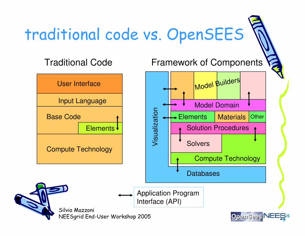
traditional code vs. OpenSEES
Compute Technology
Base Code
Elements
Input Language
User Interface
Traditional Code
Model Domain
Materials
Framework of Components
Solvers
Compute Technology
Elements
Databases
Solution Procedures
Other
Vis
ualiz
atio
n
Model Builders
Application Program Interface (API)

Silvia MazzoniNEESgrid End-User Workshop 2005
simulation-framework components
models
computation informationtechnology
Software framework,Databases, Visualization,Internet/grid computation
Algorithms,Solvers,Parallel/distributedcomputing
Simulation models,Performance models,Limit state modelsMaterial, component, system models
Open-Source CommunitySimulation Framework
Silvia MazzoniNEESgrid End-User Workshop 2005
why OpenSEES?• The library of materials, elements and analysis commands makes OpenSEES a powerful tool for numerical simulation of nonlinear structural and geotechnical systems
• The OpenSEES library of components is ever-growing and at the leading edge of numerical-simulation models
• The OpenSEES interface is based on a command-driven scripting language which enables the user to create more-versatile input files. (I’ll show you how!)
• OpenSEES is not a black box, making it a useful educational tool for numerical modeling
• You can create your own material, element or analysis tools and incorporate them into OpenSEES
• NEES is supporting integration of OpenSEES as the simulation component of laboratory testing

Silvia MazzoniNEESgrid End-User Workshop 2005
my favorite:• You can describe a structural/geotech. component at a number of levels:– element level – force-deformation model
– section level – moment-curvature model
– fiber level – material stress-strain model
integration pointselement node element node
element
section
element
section
σ
ε
V
γ
VyM
κ
Mz
fiber

Silvia MazzoniNEESgrid End-User Workshop 2005
fiber sections:
($yLoc, $zLoc)
y
z
$A
single fiber
$numBars=5
y
z
($yEnd, $zEnd)
($yStart, $zStart)
straight layer
y
z
$numBars
=5
($yCenter, $zCenter)
$startAng
$endAng
$radius
circular layer
$startAng
$endAng
$extRad $intRad
($yCenter, $zCenter)
$numSubdivCirc=4
$num
Sub
divR
ad=3
y
z
circular patch
$numSubdivIJ=4
I ($yI, $zI)
J ($yJ, $zJ)
K ($yK, $zK)
L ($yL, $zL)
$n
um
Su
bd
ivJk=
3
y
z
rectangular patch

Silvia MazzoniNEESgrid End-User Workshop 2005
OpenSEES features
• models:– linear & nonlinear structural and geotechnical models
• simulations:– static push-over analyses
– static reversed-cyclic analyses
– dynamic time-series analyses• uniform-support excitation
• multi-support excitation

Silvia MazzoniNEESgrid End-User Workshop 2005
simulation features• Model-Building
– model
– node
– mass
– Constraints
– uniaxialMaterial
– nDMaterial
– section
– element
– block
– region
– Geometric Transformation
– Time Series
– pattern
• Analysis– constraints
– numberer
– system
– test
– algorithm
– integrator
– analysis
– rayleigh
– eigen
– dataBase
• Recorders– Node – EnvelopeNode– Drift – Element – EnvelopeElement– Display – Plot – playback

Silvia MazzoniNEESgrid End-User Workshop 2005
modeling features• uniaxial materials:
– Elastic Material– Elastic-Perfectly Plastic Material– Elastic-Perfectly Plastic Gap Material– Parallel Material– Series Material– Hardening Material– Steel01 Material– Concrete01 Material– Elastic-No Tension Material– Hysteretic Material– Viscous Material– PINCHING4 Material– Fedeas Materials– PyTzQz Uniaxial Materials
• nD materials:– Elastic Isotropic Material
– J2 Plasticity Material
– Plane Stress Material
– Plate Fiber Material
– Template Elasto-Plastic Material
– FluidSolidPorousMaterial Material
– PressureIndependMultiYield Material
– PressureDependMultiYield Material
Silvia MazzoniNEESgrid End-User Workshop 2005
modeling features• elements:
– Truss
– Corotational Truss
– Elastic Beam Column
– NonLinear Beam-Column
– Zero-Length
– Quadrilateral
– Brick
– FourNodeQuadUP
– BeamColumnJoint
• sections:
– Elastic Section
– Uniaxial Section
– Fiber Section
– Section Aggregator
– Elastic Membrane Plate Section
– Plate Fiber Section
– Bidirectional Section

Silvia MazzoniNEESgrid End-User Workshop 2005
analysis features• Linear Equation Solvers -- provide the solution of the linear system of
equations Ku = P. Each solver is tailored to a specific matrix topology. – Profile SPD -- Direct profile solver for symmetric positive definite
matrices – Band General -- Direct solver for banded unsymmetric matrices – Band SPD -- Direct solver for banded symmetric positive definite
matrices – Sparse General -- Direct solver for unsymmetric sparse matrices – Sparse Symmetric -- Direct solver for symmetric sparse matrices – UmfPack General -- Direct UmfPack solver for unsymmetric matrices – Full General -- Direct solver for unsymmetric dense matrices – Conjugate Gradient -- Iterative solver using the preconditioned
conjugate gradient method • Eigenvalue Solvers -- provide the solution of the generalized eigenvalue
problem Kv = MvL– Symmetric Arpack -- Arpack solver for symmetric matrices – Band Arpack -- Arpack solver for banded matrices
Silvia MazzoniNEESgrid End-User Workshop 2005
analysis features• DOF Numberers -- number the degrees of freedom in the
domain– Plain -- Uses the numbering provided by the user – RCM -- Renumbers the DOF to minimize the matrix band-width
using the Reverse Cuthill-McKee algorithm • Static Integrators -- determine the next time step for an
analysis – Load Control -- Specifies the incremental load factor to be
applied to the loads in the domain – Displacement Control -- Specifies the incremental
displacement at a specified DOF in the domain – Minimum Unbalanced Displacement Norm -- Specifies the
incremental load factor such that the residual displacement norm in minimized
– Arc Length -- Specifies the incremental arc-length of the load-displacement path
Silvia MazzoniNEESgrid End-User Workshop 2005
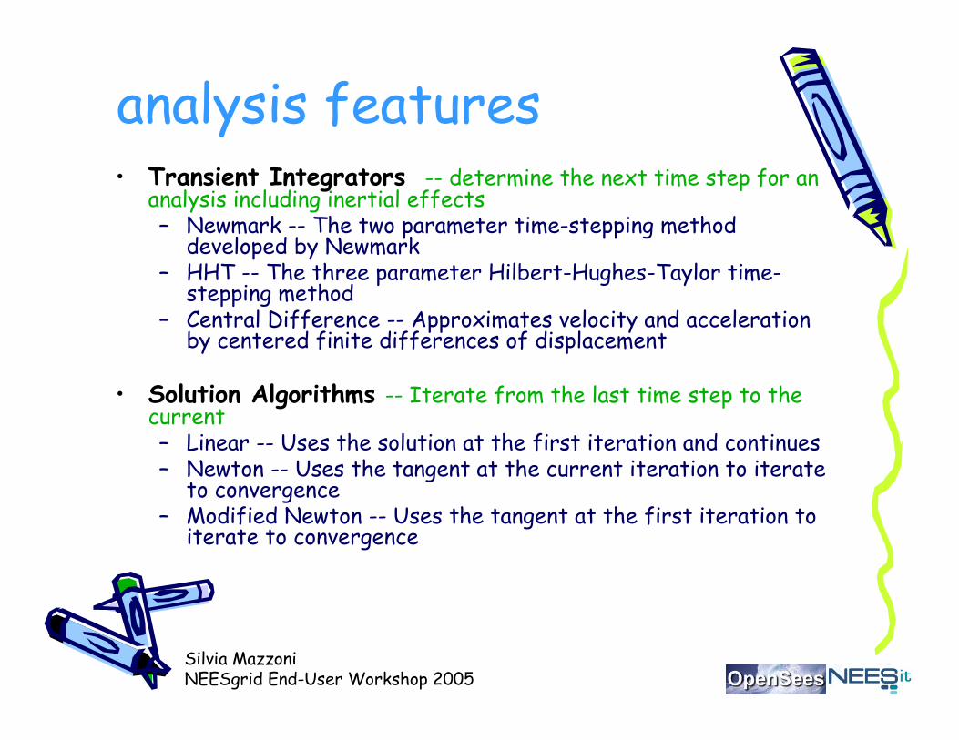
analysis features• Transient Integrators -- determine the next time step for an
analysis including inertial effects – Newmark -- The two parameter time-stepping method
developed by Newmark– HHT -- The three parameter Hilbert-Hughes-Taylor time-
stepping method – Central Difference -- Approximates velocity and acceleration
by centered finite differences of displacement
• Solution Algorithms -- Iterate from the last time step to the current– Linear -- Uses the solution at the first iteration and continues – Newton -- Uses the tangent at the current iteration to iterate
to convergence – Modified Newton -- Uses the tangent at the first iteration to
iterate to convergence
Silvia MazzoniNEESgrid End-User Workshop 2005
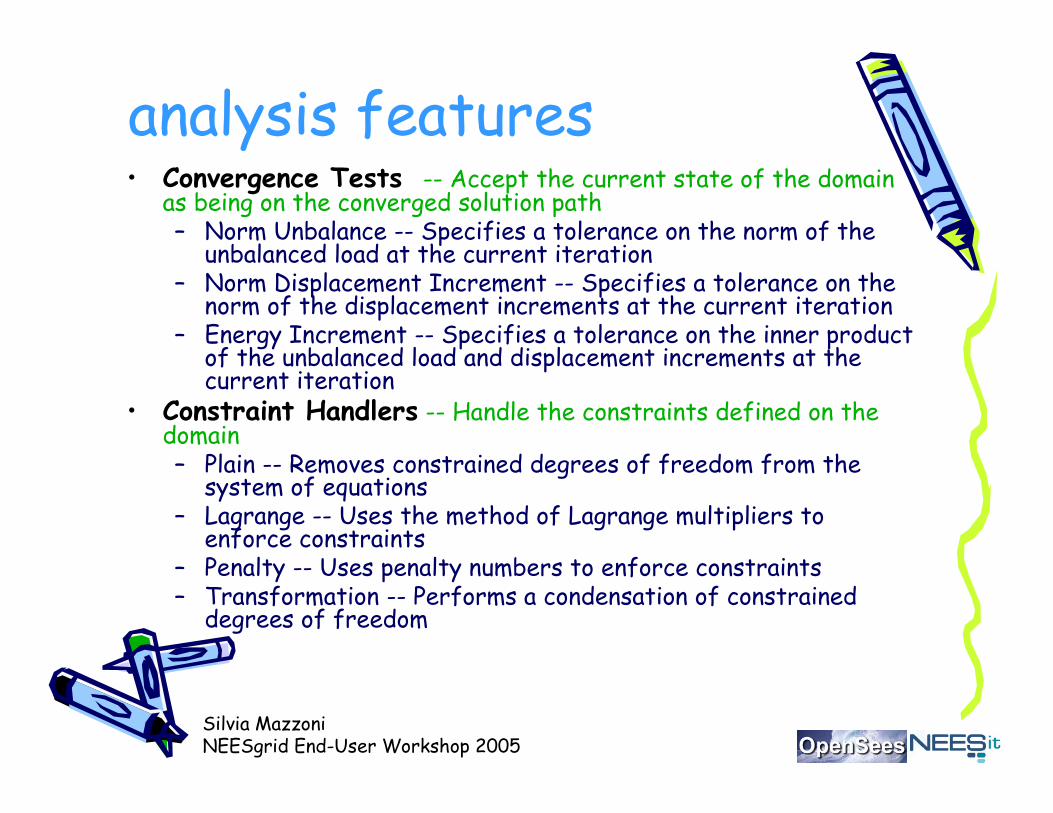
analysis features• Convergence Tests -- Accept the current state of the domain
as being on the converged solution path – Norm Unbalance -- Specifies a tolerance on the norm of the
unbalanced load at the current iteration – Norm Displacement Increment -- Specifies a tolerance on the
norm of the displacement increments at the current iteration – Energy Increment -- Specifies a tolerance on the inner product
of the unbalanced load and displacement increments at the current iteration
• Constraint Handlers -- Handle the constraints defined on the domain – Plain -- Removes constrained degrees of freedom from the
system of equations – Lagrange -- Uses the method of Lagrange multipliers to
enforce constraints – Penalty -- Uses penalty numbers to enforce constraints – Transformation -- Performs a condensation of constrained
degrees of freedom

Silvia MazzoniNEESgrid End-User Workshop 2005
OpenSEES User resources• Both an executable version and the source code are publicly available
• http://OpenSEES.berkeley.edu/• User Command Manual• Examples Manual• e-mail technical support• Annual User Workshops• The OpenSEES Community Forum
•Tcl scripting language for user interface
•NEES portal

Silvia MazzoniNEESgrid End-User Workshop 2005
Tcl scripting language• Tcl is a string based scripting language
• enables variables and variable substitution (use variables to define units!!!)
• Expression evaluation
• Array management
• Basic control structures (if , while, for, foreach)
• Procedures
• File manipulation

Silvia MazzoniNEESgrid End-User Workshop 2005
OpenSEES & Tcl
• OpenSEES Commands in Tcl for finite-element analysis:1.Modeling – create nodes, elements, loads and constraints
2.Analysis – specify the analysis procedure
3.Recorders – specify what it is the user wants to monitor during the analysis for output

Silvia MazzoniNEESgrid End-User Workshop 2005
main abstractions in OpenSEES
DomainModelBuilder Analysis
Recorder
Constructs the objectsin the model and adds them to the domain.
Monitors user-defined parameters in the model during the analysis
Moves the model from state at time ti to state at time and (ti + dt)
Holds the state of the model at time ti and (ti + dt) & is responsible for storing the objects created by the ModelBuilderobject and for providing the Analysis and Recorder objects access to these objects
all this is within theTcl interpreter & commands

Silvia MazzoniNEESgrid End-User Workshop 2005
domain & analysis objectsDomain
Element MP_Constraint SP_ConstraintNode LoadPattern TimeSeries
ElementalLoad NodalLoad SP_ConstraintMaterial
CHandler AnalysisModel SolnAlgorithmNumberer Integrator
Analysis
SystemOfEqn
Solver
Silvia MazzoniNEESgrid End-User Workshop 2005
OpenSEES User ManualA document providing the syntax and description of
OpenSEES commands in 3 formats:
1. HTML Manual – on-line HTML document, residing on OpenSEES server. Always going to be the most current.
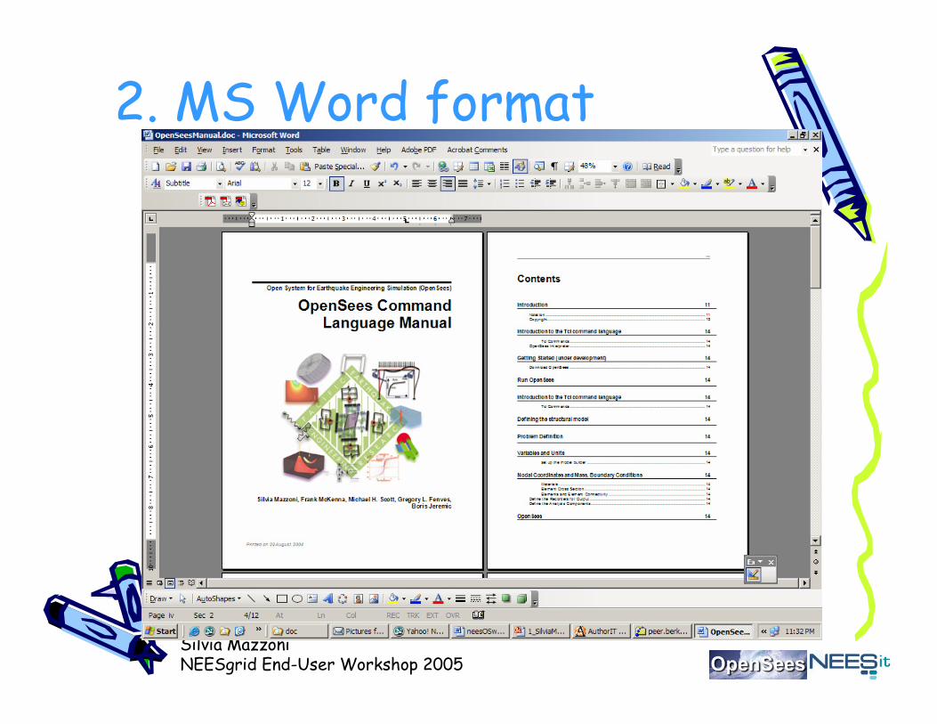
2. MS Word – downloadable and printable Word document
3. Offline Windows – downloadable .chm file. it is similar to the HTML format, but the file resides on your computer.

Silvia MazzoniNEESgrid End-User Workshop 2005
1. HTML on-line format
Silvia MazzoniNEESgrid End-User Workshop 2005
2. MS Word format

Silvia MazzoniNEESgrid End-User Workshop 2005
.chm file for MS Windows

Silvia MazzoniNEESgrid End-User Workshop 2005
annual 2-day User WorkshopAGENDA Day 1, Thursday, 2 September 2004
• Welcome and Introduction to OpenSEES & NEESgrid Simulation – Gregory Fenves• Getting Started with OpenSEES:Downloading and Installing the SoftwareIntroduction to Tcl/Tk and OpenSEES Commands -- Frank McKenna
• Introduction to the OpenSEES User Manual and Files -- Silvia Mazzoni• Structural Models I (Parameter Definition, Nodes, Constraints, Materials, Sections & Elements, Block & Region, Geometric Transformation)
• Structural Models II (Recorders, Loads) -- Silvia Mazzoni• Introduction to Analysis Commands (System, Integrator, Algorithm, NumbererAnalyze)
• When Things Go Wrong: Modifying the Script in the Event of Non-Convergence• Structural Example – Reinforced-Concrete Frame: Building the Model• Structural Example – Reinforced-Concrete Frame: Static, Cyclic and Dynamic Analyses, Multiple-Support Excitation -- Frank McKenna

Silvia MazzoniNEESgrid End-User Workshop 2005
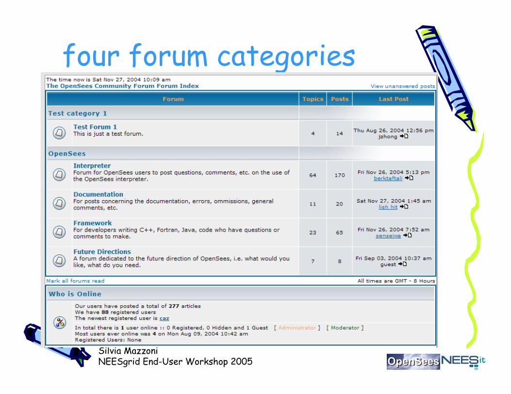
OpenSEES Community Forum
Silvia MazzoniNEESgrid End-User Workshop 2005
four forum categories

Silvia MazzoniNEESgrid End-User Workshop 2005
very busy message board

Silvia MazzoniNEESgrid End-User Workshop 2005
OpenSEES application• MiniMOST model:
6 inches
2 Bolts: each 2 inches apart. Essentially a fixed boundary condition.
2” 2” 2”
Steel beam: thickness is 0.25”, depth is 2”(dimension not shown), total length of beam including 6” at anchor is 45”)
Material Property:Young's modulus: 29000 Kip/inchMass per unit volume: 7.345*e-7 Kip/inch^3 Poisson's ration: 0.3
Sectional PropertyHeight: 2.0 inchWidth: 0.25 inchArea: 0.5 inch^2Moment of Inertia: 0.0026 inch^4
0.25”
Point load applied here under displacement control: +/- 0.394 inches (10mm)
26 inches 13 inches
Concerned about displacement measured at location of load
x
y
STEP 1

Silvia MazzoniNEESgrid End-User Workshop 2005
numerical simulation
1. Set up preliminary Tcl variables to define units and constants
2. Build the numerical model of the physical object (nodes, material, elements, connectivity, etc.)
3. Define the loading configurations
4. Define the output
5. Prescribe the analysis procedure

Silvia MazzoniNEESgrid End-User Workshop 2005
Tcl & OpenSEES commands• Comand syntax:
command arg1 arg2 …; # comment
example Tcl command:
set a 1; # assign value of 1 to a
set b [expr 2*$a];
example OpenSEES command:
node 1 10. 10. -mass $Mnode 0 0

Silvia MazzoniNEESgrid End-User Workshop 2005
example command
Note: this is taken from the user manual

Silvia MazzoniNEESgrid End-User Workshop 2005
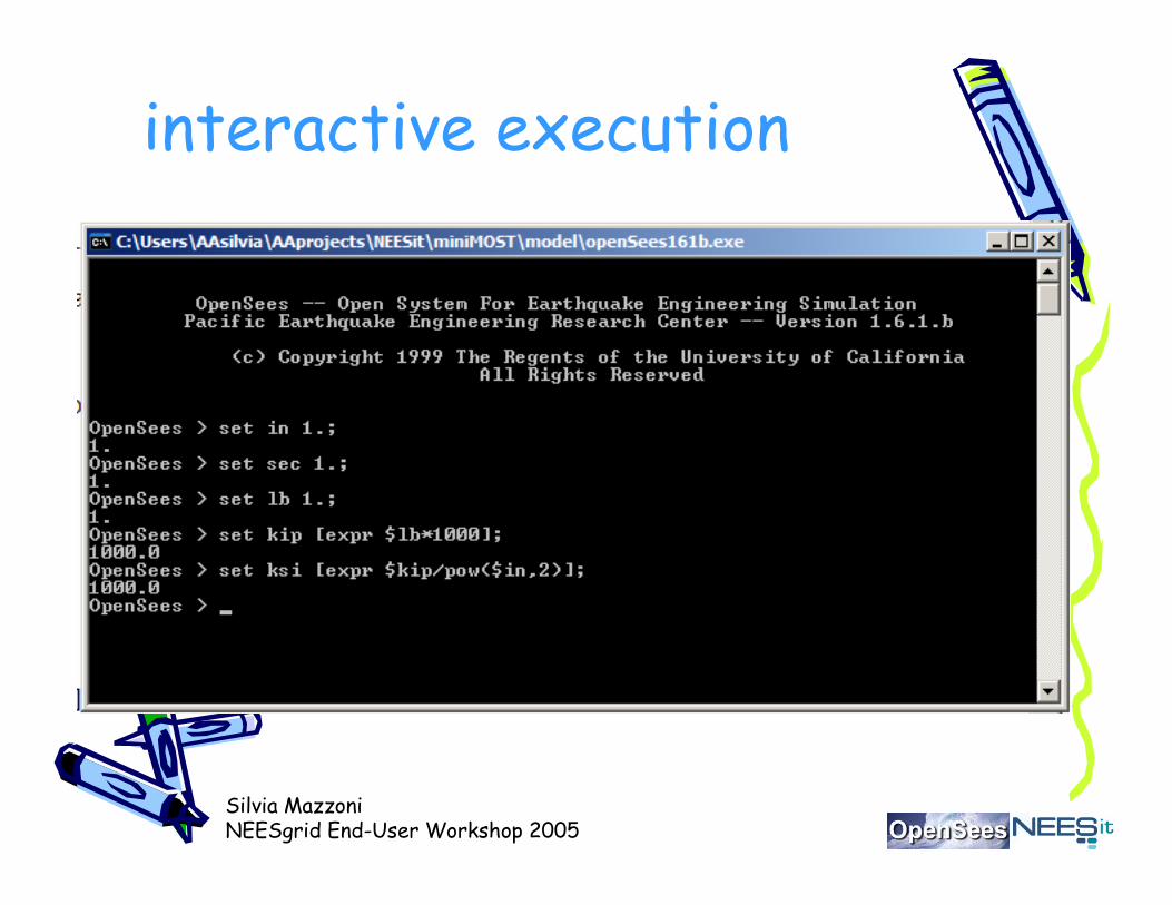
set up initial variables
# define UNITS and constants available: in, kip, ksi, psi, ft, gset in 1.; # define basic unitsset sec 1.;set lb 1.;set kip [expr $lb*1000]; # define engineering unitsset ksi [expr $kip/pow($in,2)];set psi [expr $ksi/1000.];set ft [expr 12.*$in];set PI [expr 2*asin(1.0)]; # define constantsset U 1.e10; # a really large numberset u [expr 1/$U]; # a really small numberset g [expr 32.2*$ft/pow($sec,2)]; # gravitational acceleration

Silvia MazzoniNEESgrid End-User Workshop 2005
model-builder objects• model Command• node Command• mass Command• Constraints objects• uniaxialMaterial Command• nDMaterial Command• section Command• element Command• block Command• region Command• Geometric Transformation Command• Time Series• pattern Command

Silvia MazzoniNEESgrid End-User Workshop 2005
model parameters# define GEOMETRY parametersset Hbeam [expr 2.*$in];set Bbeam [expr 0.25*$in];set IzBeam [expr $Hbeam*pow($Bbeam,3)/12];set Abeam [expr $Hbeam*$Bbeam];set Lbeam [expr (26.+13.)*$in];
# define MATERIAL parametersset Es [expr 29000.*$ksi]; # modulus of steel
# set up parameters for column section and element definitionset IDbeamTrans 1; # ID tag for beam transformation
# define displacement-cycle amplitudeset iDmaxCycl "[expr 0.394*$in]“
wipe; # clear analysis memory

Silvia MazzoniNEESgrid End-User Workshop 2005
model-building commands# Create modelbuildermodel basic -ndm 2 -ndf 3; # ndm= number of dimensions, ndf= #dof/node
# Define nodes ------ frame is in X-Y plane (X-horizontal, Y-vertical)node 1 0. 0.node 2 [expr 2*$Lbeam/3] 0.node 3 [expr $Lbeam] 0.
# identify some node tagsset IDctrlNode 2; # control node: where displ./forces are appliedset IDendNode 3; # identify node ID for free end of beam
# Boundary conditionsfix 1 1 1 1 1 1 1fix 2 0 0 0 0 0 0fix 3 0 0 0 0 0 0
# Define BEAM elementsgeomTransf Linear $IDbeamTranselement elasticBeamColumn 1 1 2 $Abeam $Es $IzBeam $IDbeamTranselement elasticBeamColumn 2 2 3 $Abeam $Es $IzBeam $IDbeamTrans
Silvia MazzoniNEESgrid End-User Workshop 2005
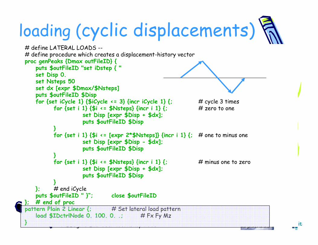
loading (cyclic displacements)# define LATERAL LOADS --# define procedure which creates a displacement-history vectorproc genPeaks {Dmax outFileID} {
puts $outFileID "set iDstep { "set Disp 0.set Nsteps 50set dx [expr $Dmax/$Nsteps]puts $outFileID $Dispfor {set iCycle 1} {$iCycle <= 3} {incr iCycle 1} {; # cycle 3 times
for {set i 1} {$i <= $Nsteps} {incr i 1} {; # zero to oneset Disp [expr $Disp + $dx];puts $outFileID $Disp
}for {set i 1} {$i <= [expr 2*$Nsteps]} {incr i 1} {; # one to minus one
set Disp [expr $Disp - $dx];puts $outFileID $Disp
}for {set i 1} {$i <= $Nsteps} {incr i 1} {; # minus one to zero
set Disp [expr $Disp + $dx];puts $outFileID $Disp
}}; # end iCycleputs $outFileID " }“; close $outFileID
}; # end of procpattern Plain 2 Linear {; # Set lateral load pattern
load $IDctrlNode 0. 100. 0. .; # Fx Fy Mz}

Silvia MazzoniNEESgrid End-User Workshop 2005
recorder objects• Node Recorder
• EnvelopeNode Recorder
• MaxNodeDisp Recorder
• Drift Recorder
• Element Recorder
• EnvelopeElement Recorder
• Display Recorder
• Plot Recorder
• playback Command

Silvia MazzoniNEESgrid End-User Workshop 2005
output commands# Record nodal displacements -NODAL DISPLACEMENTS# ALL displs where load is applied and at free end of the beamset iNode "$IDctrlNode $IDendNode";foreach xNode $iNode {
set Dfile DNode$xNoderecorder Node -file $Dfile.out -time -node $xNode -dof 1 2 3 disp;
}; # end of xNode# Record vertical-y displacement of ALL nodesset DfileALL DNodeALLrecorder Node -file $DfileALL.out -time -node all -dof 2 disp;
# Record REACTION FORCES - (=forces in element 1)set iEL "1"foreach xEL $iEL {
set Ffile FEl[expr $xEL]recorder Element -file $Ffile.out -time -ele $xEL localForce
}; # end of xEL

Silvia MazzoniNEESgrid End-User Workshop 2005
analysis objects• constraints Command• numberer Command• analysis Command• algorithm Command• integrator Command• system Command• test Command• analyze Command• rayleigh command• eigen Command• dataBase Commands
Silvia MazzoniNEESgrid End-User Workshop 2005
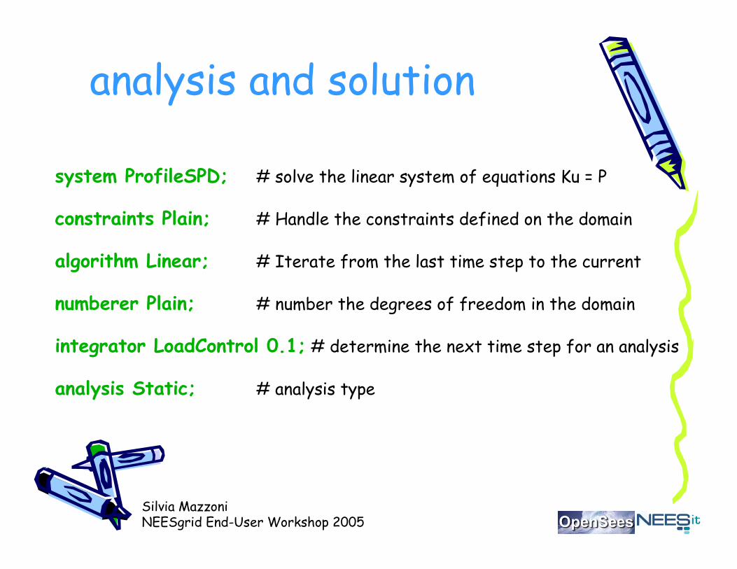
analysis and solution
system ProfileSPD; # solve the linear system of equations Ku = P
constraints Plain; # Handle the constraints defined on the domain
algorithm Linear; # Iterate from the last time step to the current
numberer Plain; # number the degrees of freedom in the domain
integrator LoadControl 0.1; # determine the next time step for an analysis
analysis Static; # analysis type

Silvia MazzoniNEESgrid End-User Workshop 2005
cyclicl displacement solnset DOF 2foreach Dmax $iDmaxCycl {
set outFileID [open Dsteps.tcl w]genPeaks $Dmax $outFileIDsource Dsteps.tclset D0 0.0foreach Dstep $iDstep {
set D1 $Dstepset Dincr [expr $D1 - $D0]integrator DisplacementControl $IDctrlNode
$DOF $Dincr 1 $Dincr $Dincrset ok [analyze 1]set D0 $D1
}}; # end of iDmaxCycl
Silvia MazzoniNEESgrid End-User Workshop 2005
interactive execution
Silvia MazzoniNEESgrid End-User Workshop 2005
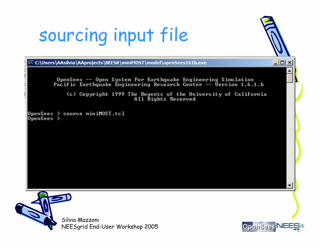
sourcing input file

Silvia MazzoniNEESgrid End-User Workshop 2005
matlab post-processingcd ………\model\data% UNITS: pound, inch, secload DNode2.outload DNode3.outload DNodeAll.outload FEl1.out
figuresubplot(2,1,1)plot(DNode2(:,3)); title('Y-displacement at node 2')xlabel('step')ylabel('inch')gridsubplot(2,1,2)plot(DNode2(:,4)); title('Rotation at node 2')gridxlabel('step')ylabel('radian') …………

Silvia MazzoniNEESgrid End-User Workshop 2005
figures
0 100 200 300 400 500 600 700-0.4
-0.2
0
0.2
0.4Y-displacement at node 2
step
inch
0 100 200 300 400 500 600 700-0.04
-0.02
0
0.02
0.04Rotation at node 2
step
radia
n
-0.4 -0.3 -0.2 -0.1 0 0.1 0.2 0.3 0.4-6
-4
-2
0
2
4
6
applied disp., inch
applie
d load,
pound
Applied Force-Deformation
0 100 200 300 400 500 600 700-0.8
-0.6
-0.4
-0.2
0
0.2
0.4
0.6
0.8Y-displacement of all nodes
step
inch

Silvia MazzoniNEESgrid End-User Workshop 2005
NEESit Simulation Overview
Compute Resources
Data Repository
OpenS
ees
NC
TP
Plu
gin
SimulationPortal

Silvia MazzoniNEESgrid End-User Workshop 2005
SPURport Architecture
Tele-presence
NEESpop (middleware)
MSU extensions(Enterprise Computational System)
ApacheTomcat
JetSpeedChef
NEESgrid services
DBMS(postgress)
EJB container(JBoss)
OGSI(Globus 3.0)
ECSapplicationstreaming
device driver
Data Controller
Data streaming andchannel management
Authentication andauthorization
SPURapplet
Request
Data
NSDS
Data andMetadata
Collaboration
ERCat Mississippi State
PSC NCSA
OpenSees OpenSeesGround Motion
DataStruct. Resp.
Data
Ground MotionData
Front End
Back End

Silvia MazzoniNEESgrid End-User Workshop 2005
FedeasMatLab Toolbox forStructural Simulation
• Need for Matlab toolbox in NEES.
– Research
– Education
• Relationship between FedeasLab and OpenSees.

Silvia MazzoniNEESgrid End-User Workshop 2005
Questions,or statements!
The OpenSees Community Forum:http://opensees.berkeley.edu/phpBB2/index.php
which can be accessed from:
http://opensees.berkeley.edu

Silvia MazzoniNEESgrid End-User Workshop 2005
thank you!!!