OpenAir GQD Series SR 20 lb-in Rotary Electronic Damper ...
12
OpenAir® GQD Series Technical Instructions Document No. 155-760 EA GQD May 19, 2014 Spring Return, 20 lb-in (2 Nm), Rotary Electronic Damper Actuators Siemens Industry, Inc. Description The OpenAir GQD Series direct-coupled spring return electronic actuator is designed for modulating, two-position, and floating control of building HVAC dampers. Features • Bi-directional spring return (fail-safe) • Pre-cabled • Plenum-rated models available • Optional built-in auxiliary switches with fixed switch points at 5° and 85° rotation • Auxiliary switch units shipped with separate conduit box • Fast run time • Available in 20 lb-in (2 Nm) torque • Signal inversion capability on modulating types (2 to 10 Vdc or 10 to 2 Vdc) • UL and cUL listed, CE certified • Compact footprint • Low voltage models are 24 Vac/dc compatible • 120 Vac model with 1/2" NPT conduit connection Application Used in constant or variable air volume installations for the control of return air, mixed air, exhaust, and face and bypass, and residential zone dampers requiring up to 20 lb- in (2 Nm) torque. Designed for applications that require the damper to return to a fail-safe position when there is a power failure. Product Numbers Table 1. Product Number* Torque Voltage Control Signals Plenum Cabling Appliance Cable Auxiliary Switch 20 lb-in 24 Vac/dc 120 Vac 2-Position Floating Modulating 2 to 10 Vdc/ 10 to 2 Vdc GQD121.1P — — — — — GQD126.1P — — — GQD131.1P — — — — — GQD136.1P — — — — GQD151.1P — — — — — GQD156.1P — — — — GQD221.1U — — — — — GQD226.1U — — — — NOTE: Add /B to part numbers to order bulk packs of 10.
Transcript of OpenAir GQD Series SR 20 lb-in Rotary Electronic Damper ...
OpenAir® GQD Series
Technical Instructions Document No. 155-760
EA GQD May 19, 2014
Spring Return, 20 lb-in (2 Nm), Rotary Electronic Damper Actuators
Siemens Industry, Inc.
Description The OpenAir GQD Series direct-coupled spring return electronic actuator is designed for modulating, two-position, and floating control of building HVAC dampers.
Features • Bi-directional spring return (fail-safe) • Pre-cabled • Plenum-rated models available • Optional built-in auxiliary switches with fixed switch points at 5° and 85° rotation • Auxiliary switch units shipped with separate conduit box • Fast run time • Available in 20 lb-in (2 Nm) torque • Signal inversion capability on modulating types (2 to 10 Vdc or 10 to 2 Vdc) • UL and cUL listed, CE certified • Compact footprint • Low voltage models are 24 Vac/dc compatible • 120 Vac model with 1/2" NPT conduit connection
Application Used in constant or variable air volume installations for the control of return air, mixed air, exhaust, and face and bypass, and residential zone dampers requiring up to 20 lb-in (2 Nm) torque.
Designed for applications that require the damper to return to a fail-safe position when there is a power failure.
Product Numbers Table 1.
Product Number*
Torque Voltage Control Signals
Plen
um C
ablin
g
App
lianc
e C
able
Aux
iliar
y Sw
itch
20 lb
-in
24 V
ac/d
c
120
Vac
2-Po
sitio
n
Floa
ting
Mod
ulat
ing
2 to
10
Vdc/
10
to 2
Vdc
GQD121.1P — — — — — GQD126.1P — — — GQD131.1P — — — — — GQD136.1P — — — — GQD151.1P — — — — — GQD156.1P — — — — GQD221.1U — — — — — GQD226.1U — — — —
NOTE: Add /B to part numbers to order bulk packs of 10.
Technical Instructions OpenAir® GQD Series, Spring Return, 20 lb-in, Rotary, Electronic Damper Actuators Document Number 155-760 May 19, 2014
Page 2 Siemens Industry, Inc.
Warning/Caution Notations
WARNING:
Personal injury/loss of life may occur if you do not perform a procedure as specified.
CAUTION:
Equipment damage may occur if you do not perform a procedure as specified.
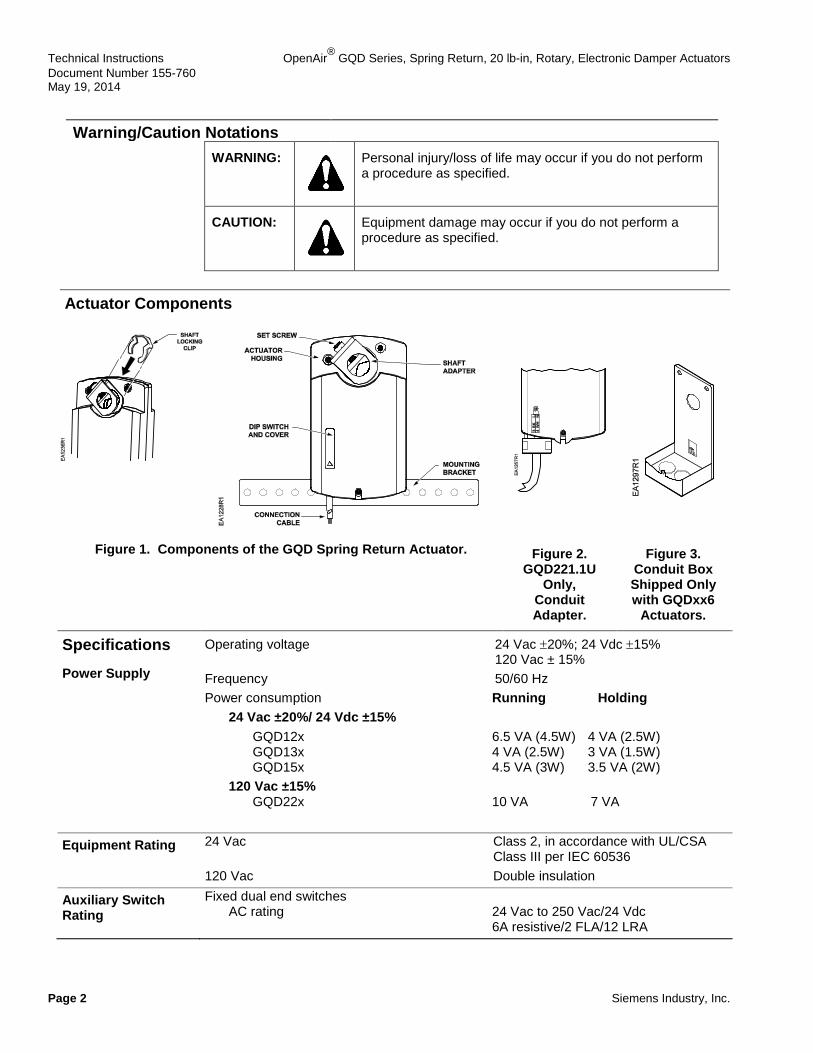
Actuator Components
Figure 1. Components of the GQD Spring Return Actuator.
Figure 2. GQD221.1U
Only, Conduit Adapter.
Figure 3. Conduit Box Shipped Only with GQDxx6
Actuators.
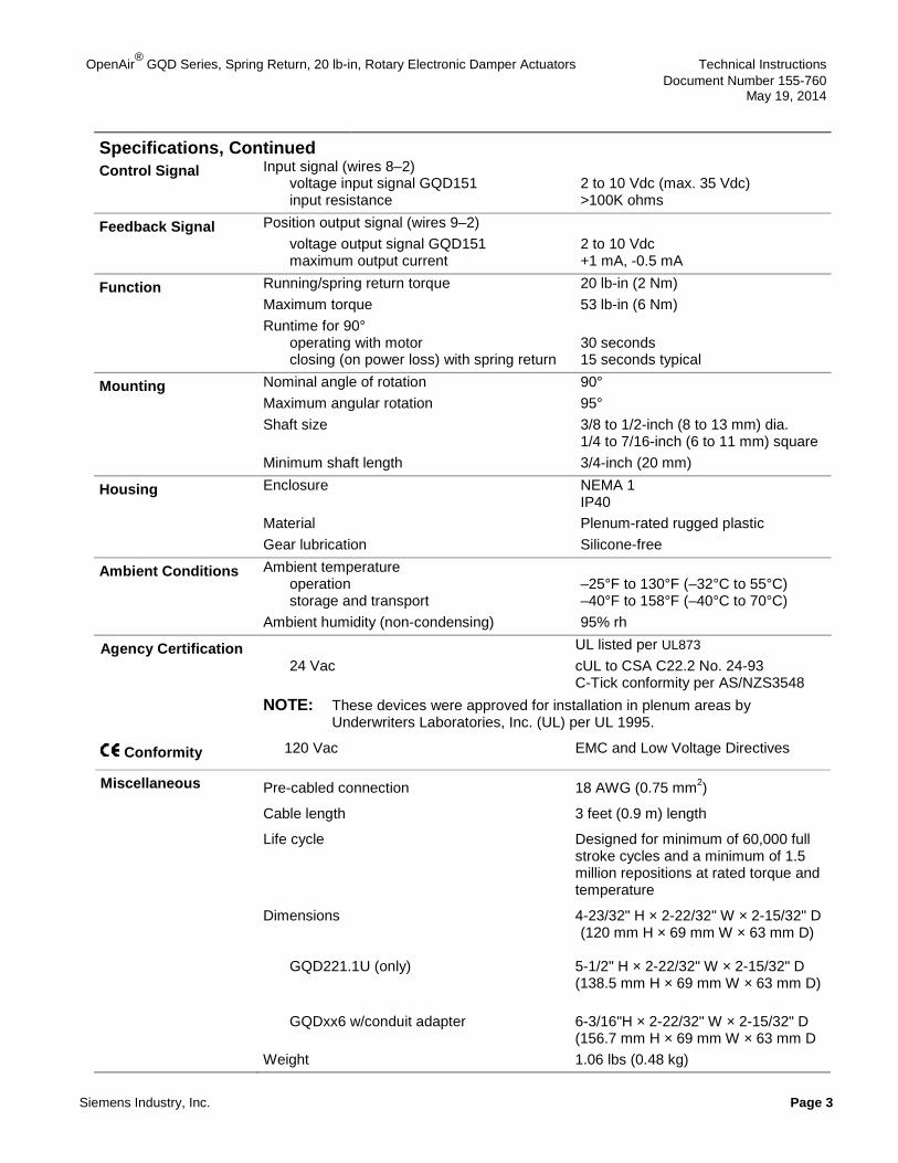
Specifications Power Supply
Operating voltage 24 Vac ±20%; 24 Vdc ±15% 120 Vac ± 15% Frequency 50/60 Hz Power consumption Running Holding 24 Vac ±20%/ 24 Vdc ±15% GQD12x 6.5 VA (4.5W) 4 VA (2.5W) GQD13x 4 VA (2.5W) 3 VA (1.5W) GQD15x 4.5 VA (3W) 3.5 VA (2W) 120 Vac ±15% GQD22x 10 VA 7 VA
Equipment Rating 24 Vac Class 2, in accordance with UL/CSA Class III per IEC 60536 120 Vac Double insulation
Auxiliary Switch Rating
Fixed dual end switches AC rating 24 Vac to 250 Vac/24 Vdc 6A resistive/2 FLA/12 LRA
OpenAir® GQD Series, Spring Return, 20 lb-in, Rotary Electronic Damper Actuators Technical Instructions Document Number 155-760
May 19, 2014
Siemens Industry, Inc. Page 3
Specifications, Continued
Control Signal Input signal (wires 8–2) voltage input signal GQD151 2 to 10 Vdc (max. 35 Vdc) input resistance >100K ohms
Feedback Signal Position output signal (wires 9–2) voltage output signal GQD151 2 to 10 Vdc maximum output current +1 mA, -0.5 mA
Function Running/spring return torque 20 lb-in (2 Nm) Maximum torque 53 lb-in (6 Nm) Runtime for 90° operating with motor 30 seconds closing (on power loss) with spring return 15 seconds typical
Mounting Nominal angle of rotation 90° Maximum angular rotation 95° Shaft size 3/8 to 1/2-inch (8 to 13 mm) dia. 1/4 to 7/16-inch (6 to 11 mm) square Minimum shaft length 3/4-inch (20 mm)
Housing Enclosure NEMA 1 IP40 Material Plenum-rated rugged plastic Gear lubrication Silicone-free
Ambient Conditions Ambient temperature operation –25°F to 130°F (–32°C to 55°C) storage and transport –40°F to 158°F (–40°C to 70°C) Ambient humidity (non-condensing) 95% rh
Agency Certification UL listed per UL873 24 Vac cUL to CSA C22.2 No. 24-93 C-Tick conformity per AS/NZS3548 NOTE: These devices were approved for installation in plenum areas by
Underwriters Laboratories, Inc. (UL) per UL 1995.
Conformity 120 Vac EMC and Low Voltage Directives
Miscellaneous Pre-cabled connection 18 AWG (0.75 mm2)
Cable length 3 feet (0.9 m) length
Life cycle Designed for minimum of 60,000 full stroke cycles and a minimum of 1.5 million repositions at rated torque and temperature
Dimensions 4-23/32" H × 2-22/32" W × 2-15/32" D (120 mm H × 69 mm W × 63 mm D) GQD221.1U (only) 5-1/2" H × 2-22/32" W × 2-15/32" D (138.5 mm H × 69 mm W × 63 mm D) GQDxx6 w/conduit adapter 6-3/16"H × 2-22/32" W × 2-15/32" D (156.7 mm H × 69 mm W × 63 mm D Weight 1.06 lbs (0.48 kg)
Technical Instructions OpenAir® GQD Series, Spring Return, 20 lb-in, Rotary, Electronic Damper Actuators Document Number 155-760 May 19, 2014
Page 4 Siemens Industry, Inc.
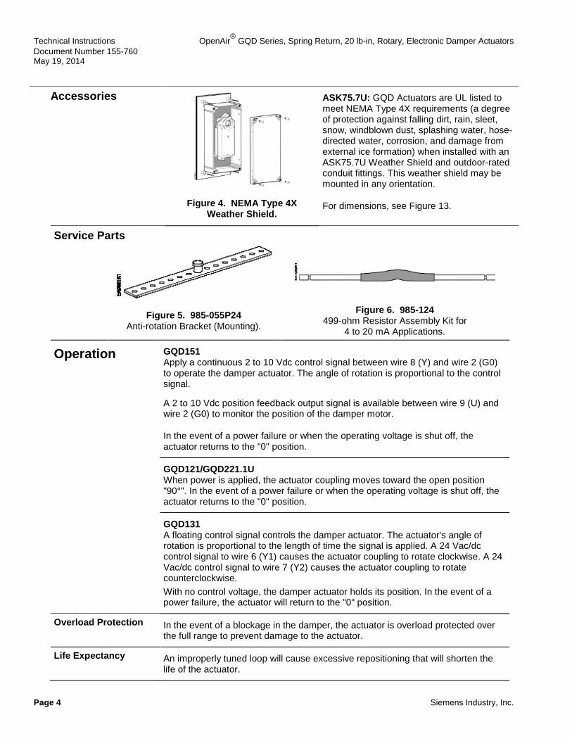
Accessories
Figure 4. NEMA Type 4X Weather Shield.
ASK75.7U: GQD Actuators are UL listed to meet NEMA Type 4X requirements (a degree of protection against falling dirt, rain, sleet, snow, windblown dust, splashing water, hose-directed water, corrosion, and damage from external ice formation) when installed with an ASK75.7U Weather Shield and outdoor-rated conduit fittings. This weather shield may be mounted in any orientation.
For dimensions, see Figure 13.
Service Parts
Figure 5. 985-055P24
Anti-rotation Bracket (Mounting).
Figure 6. 985-124 499-ohm Resistor Assembly Kit for
4 to 20 mA Applications.
Operation GQD151 Apply a continuous 2 to 10 Vdc control signal between wire 8 (Y) and wire 2 (G0) to operate the damper actuator. The angle of rotation is proportional to the control signal.
A 2 to 10 Vdc position feedback output signal is available between wire 9 (U) and wire 2 (G0) to monitor the position of the damper motor.
In the event of a power failure or when the operating voltage is shut off, the actuator returns to the "0" position.
GQD121/GQD221.1U When power is applied, the actuator coupling moves toward the open position "90°". In the event of a power failure or when the operating voltage is shut off, the actuator returns to the "0" position.
GQD131 A floating control signal controls the damper actuator. The actuator's angle of rotation is proportional to the length of time the signal is applied. A 24 Vac/dc control signal to wire 6 (Y1) causes the actuator coupling to rotate clockwise. A 24 Vac/dc control signal to wire 7 (Y2) causes the actuator coupling to rotate counterclockwise. With no control voltage, the damper actuator holds its position. In the event of a power failure, the actuator will return to the "0" position.
Overload Protection In the event of a blockage in the damper, the actuator is overload protected over the full range to prevent damage to the actuator.
Life Expectancy An improperly tuned loop will cause excessive repositioning that will shorten the life of the actuator.
OpenAir® GQD Series, Spring Return, 20 lb-in, Rotary Electronic Damper Actuators Technical Instructions Document Number 155-760
May 19, 2014
Siemens Industry, Inc. Page 5
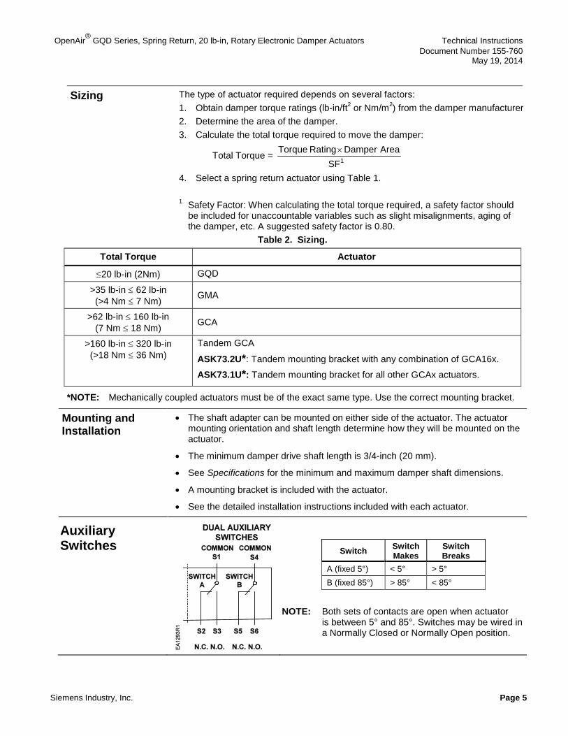
Sizing The type of actuator required depends on several factors: 1. Obtain damper torque ratings (lb-in/ft2 or Nm/m2) from the damper manufacturer 2. Determine the area of the damper. 3. Calculate the total torque required to move the damper:
Total Torque = SF
AreaDamper Rating Torque1×
4. Select a spring return actuator using Table 1. 1 Safety Factor: When calculating the total torque required, a safety factor should
be included for unaccountable variables such as slight misalignments, aging of the damper, etc. A suggested safety factor is 0.80.
Table 2. Sizing.
Total Torque Actuator
≤20 lb-in (2Nm) GQD
>35 lb-in ≤ 62 lb-in (>4 Nm ≤ 7 Nm) GMA
>62 lb-in ≤ 160 lb-in (7 Nm ≤ 18 Nm) GCA
>160 lb-in ≤ 320 lb-in (>18 Nm ≤ 36 Nm)
Tandem GCA
ASK73.2U*: Tandem mounting bracket with any combination of GCA16x.
ASK73.1U*: Tandem mounting bracket for all other GCAx actuators.
*NOTE: Mechanically coupled actuators must be of the exact same type. Use the correct mounting bracket.
Mounting and Installation
• The shaft adapter can be mounted on either side of the actuator. The actuator mounting orientation and shaft length determine how they will be mounted on the actuator.
• The minimum damper drive shaft length is 3/4-inch (20 mm).
• See Specifications for the minimum and maximum damper shaft dimensions.
• A mounting bracket is included with the actuator.
• See the detailed installation instructions included with each actuator.
Auxiliary Switches
Switch Switch Makes
Switch Breaks
A (fixed 5°) < 5° > 5° B (fixed 85°) > 85° < 85°
NOTE: Both sets of contacts are open when actuator is between 5° and 85°. Switches may be wired in a Normally Closed or Normally Open position.
Technical Instructions OpenAir® GQD Series, Spring Return, 20 lb-in, Rotary, Electronic Damper Actuators Document Number 155-760 May 19, 2014
Page 6 Siemens Industry, Inc.
CAUTION: Mixed switch operation to the switching outputs of both dual end switches (5° and 85°) is not permitted. Either AC line voltage from the same phase must be applied to all four outputs of the fixed dual end switches, or UL-Class 2 voltage must be applied to all four outputs.
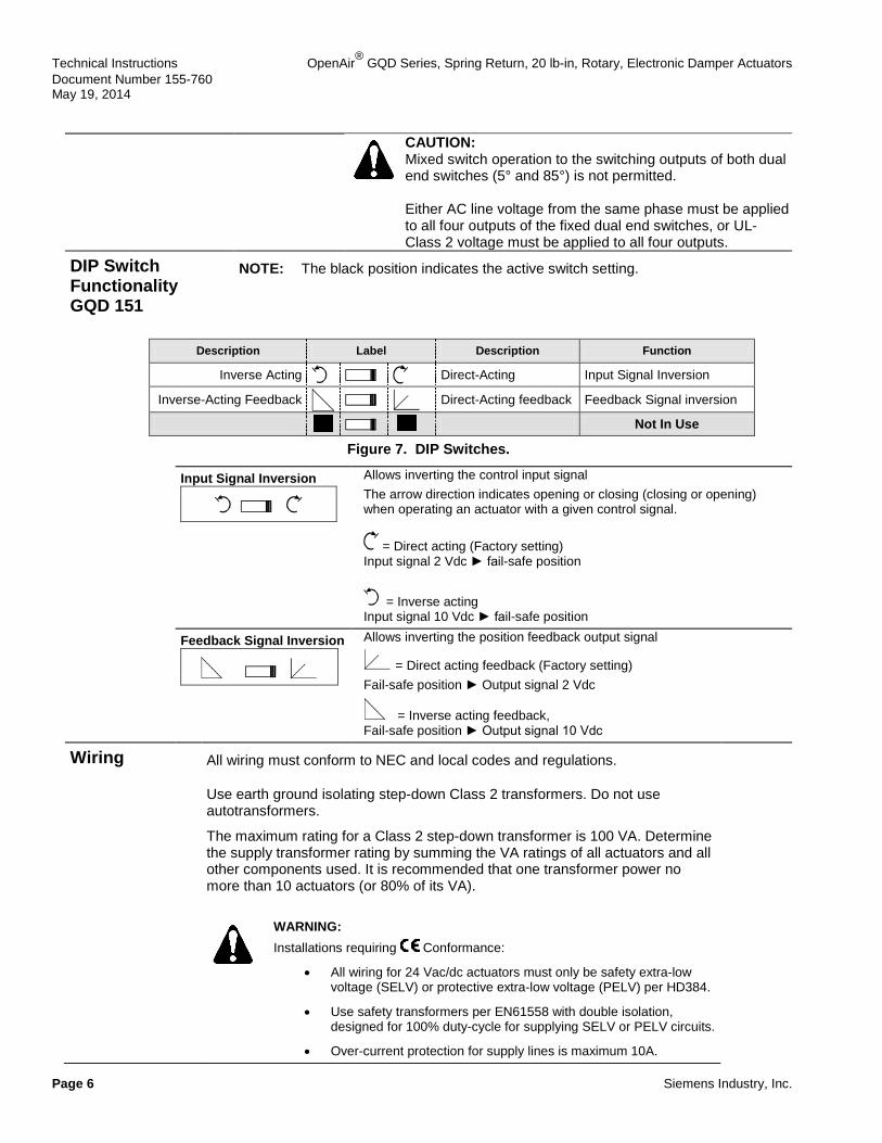
DIP Switch Functionality GQD 151
NOTE: The black position indicates the active switch setting.
Description Label Description Function
Inverse Acting Direct-Acting Input Signal Inversion
Inverse-Acting Feedback Direct-Acting feedback Feedback Signal inversion
Not In Use
Figure 7. DIP Switches.
Input Signal Inversion
Allows inverting the control input signal The arrow direction indicates opening or closing (closing or opening) when operating an actuator with a given control signal.
= Direct acting (Factory setting) Input signal 2 Vdc ► fail-safe position
= Inverse acting Input signal 10 Vdc ► fail-safe position
Feedback Signal Inversion
Allows inverting the position feedback output signal
= Direct acting feedback (Factory setting) Fail-safe position ► Output signal 2 Vdc
= Inverse acting feedback, Fail-safe position ► Output signal 10 Vdc
Wiring All wiring must conform to NEC and local codes and regulations.
Use earth ground isolating step-down Class 2 transformers. Do not use autotransformers.
The maximum rating for a Class 2 step-down transformer is 100 VA. Determine the supply transformer rating by summing the VA ratings of all actuators and all other components used. It is recommended that one transformer power no more than 10 actuators (or 80% of its VA).
WARNING: Installations requiring Conformance:
• All wiring for 24 Vac/dc actuators must only be safety extra-low voltage (SELV) or protective extra-low voltage (PELV) per HD384.
• Use safety transformers per EN61558 with double isolation, designed for 100% duty-cycle for supplying SELV or PELV circuits.
• Over-current protection for supply lines is maximum 10A.
OpenAir® GQD Series, Spring Return, 20 lb-in, Rotary Electronic Damper Actuators Technical Instructions Document Number 155-760
May 19, 2014
Siemens Industry, Inc. Page 7
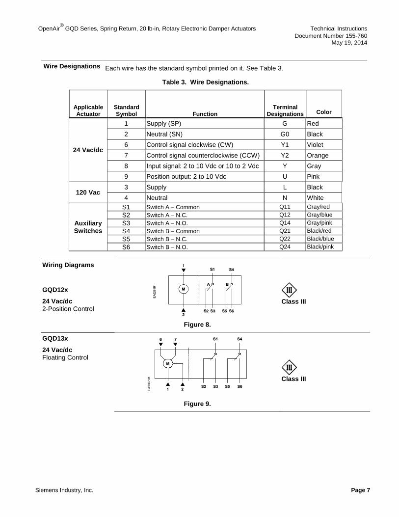
Wire Designations Each wire has the standard symbol printed on it. See Table 3.
Table 3. Wire Designations.
Applicable Actuator
Standard Symbol Function
Terminal Designations Color
24 Vac/dc
1 Supply (SP) G Red 2 Neutral (SN) G0 Black 6 Control signal clockwise (CW) Y1 Violet 7 Control signal counterclockwise (CCW) Y2 Orange 8 Input signal: 2 to 10 Vdc or 10 to 2 Vdc Y Gray 9 Position output: 2 to 10 Vdc U Pink
120 Vac 3 Supply L Black 4 Neutral N White
Auxiliary Switches
S1 Switch A − Common Q11 Gray/red S2 Switch A − N.C. Q12 Gray/blue S3 Switch A − N.O. Q14 Gray/pink S4 Switch B − Common Q21 Black/red S5 Switch B − N.C. Q22 Black/blue S6 Switch B − N.O. Q24 Black/pink
Wiring Diagrams
GQD12x
24 Vac/dc 2-Position Control
Figure 8.
Class III
GQD13x
24 Vac/dc Floating Control
Figure 9.
Class III
Technical Instructions OpenAir® GQD Series, Spring Return, 20 lb-in, Rotary, Electric Damper Actuators Document Number 155-760 May 19, 2014
Page 8 Siemens Industry, Inc.
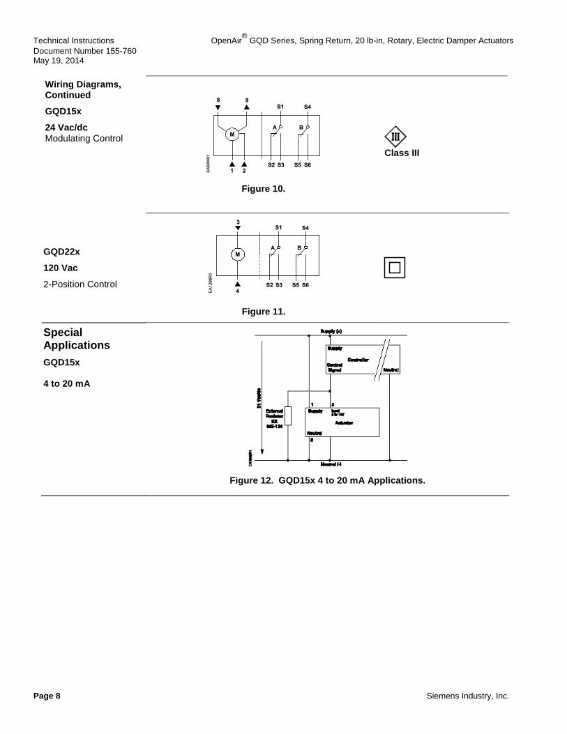
Wiring Diagrams, Continued
GQD15x
24 Vac/dc Modulating Control
Figure 10.
Class III
GQD22x
120 Vac
2-Position Control
Figure 11.
Special Applications GQD15x 4 to 20 mA
Figure 12. GQD15x 4 to 20 mA Applications.

OpenAir® GQD Series, Spring Return, 20 lb-in, Rotary, Electronic Damper Actuators Technical Instructions Document Number 155-760 May 19, 2014
Siemens Industry, Inc. Page 9
Start-Up/ Commissioning GQD15x
Spring Return Modulating Control 24 Vac/dc
1. Check Operation: a. Connect wires 1 (red) and 2 (black) to the 24 Vac/dc power supply.
NOTE: With no input signal present, the GQD151 actuator with input signal inversion switch set to Inverse Acting, will start driving towards 90°.
b. Use a Digital Multimeter (DDM) and set the dial to Vdc for the actuator input signal. c. Connect wires 2 (black) and 8 (gray) to the DMM.
d. Apply to input signal wire 8 (gray): Y = 10 Vdc (GQD151 with input signal inversion switch set to Direct Acting). Y = 2 Vdc (GQD151 with input signal inversion switch set to Inverse Acting).
Allow the actuator shaft coupling to rotate from 0° to 90°.
e. Apply to input signal wire 8 (gray): Y = 2 Vdc (GQD151 with input signal inversion switch set to Direct Acting). Y = 10 Vdc (GQD151 with input signal inversion switch set to Inverse Acting).
The shaft coupling returns to the "0" position.
2. Check Spring Return: a. Set the DMM dial to Vdc. b. Connect wires 2 (black) and 8 (gray) to the DMM.
c. Apply to input signal wire 8 (gray): Y = 6 Vdc (GQD151).
Allow the actuator shaft coupling to rotate halfway.
d. Disconnect wire 1 (red).
The spring returns the actuator shaft coupling to the fail-safe "0" position.
e. Connect wire 1 (red) and the actuator moves.
3. Check Feedback: a. Set the DMM dial to Vdc. b. Attach wires 2 (black) and 9 (pink) to the DMM. c. Apply the input signal as in Step 1d, to wire 8 (gray).
• The reading at the DMM should increase (decrease for GQD151 with output signal inversion switch set to Inverse Acting Feedback).
• The reading at the DMM should decrease (increase for GQD 151 with output signal inversion switch set to Inverse Acting Feedback) and the actuator shaft coupling returns to the fail-safe "0" position.
GQD12x
Spring Return 2-Position 24 Vac/dc
1. Check Operation: a. Connect wires 1 (red) and 2 (black) to 24 Vac/dc power supply.
Allow the actuator shaft coupling to rotate from 0° to 90°. b. Disconnect wire 1 (red) and the actuator shaft coupling returns to the "0" position.
2. Check Spring Return: a. Connect wire 1 (red).
Allow the actuator shaft coupling to rotate halfway. b. Disconnect wire 1 (red).
The spring returns the actuator shaft coupling to the fail-safe "0" position.
Technical Instructions OpenAir® GQD Series, Spring Return, 20 lb-in, Rotary, Electric Damper Actuators Document Number 155-760 May 19, 2014
Page 10 Siemens Industry, Inc.
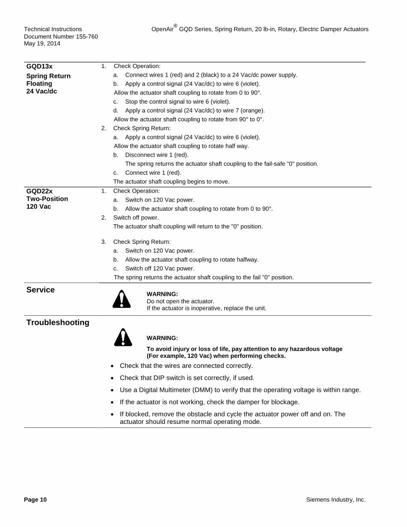
GQD13x Spring Return Floating 24 Vac/dc
1. Check Operation: a. Connect wires 1 (red) and 2 (black) to a 24 Vac/dc power supply. b. Apply a control signal (24 Vac/dc) to wire 6 (violet). Allow the actuator shaft coupling to rotate from 0 to 90°. c. Stop the control signal to wire 6 (violet). d. Apply a control signal (24 Vac/dc) to wire 7 (orange). Allow the actuator shaft coupling to rotate from 90° to 0°.
2. Check Spring Return: a. Apply a control signal (24 Vac/dc) to wire 6 (violet). Allow the actuator shaft coupling to rotate half way. b. Disconnect wire 1 (red).
The spring returns the actuator shaft coupling to the fail-safe "0" position. c. Connect wire 1 (red). The actuator shaft coupling begins to move.
GQD22x Two-Position 120 Vac
1. Check Operation: a. Switch on 120 Vac power. b. Allow the actuator shaft coupling to rotate from 0 to 90°.
2. Switch off power. The actuator shaft coupling will return to the "0" position.
3. Check Spring Return: a. Switch on 120 Vac power. b. Allow the actuator shaft coupling to rotate halfway. c. Switch off 120 Vac power. The spring returns the actuator shaft coupling to the fail "0" position.
Service
WARNING: Do not open the actuator. If the actuator is inoperative, replace the unit.
Troubleshooting
WARNING:
To avoid injury or loss of life, pay attention to any hazardous voltage (For example, 120 Vac) when performing checks.
• Check that the wires are connected correctly.
• Check that DIP switch is set correctly, if used.
• Use a Digital Multimeter (DMM) to verify that the operating voltage is within range.
• If the actuator is not working, check the damper for blockage.
• If blocked, remove the obstacle and cycle the actuator power off and on. The actuator should resume normal operating mode.
OpenAir® GQD Series, Spring Return, 20 lb-in, Rotary, Electronic Damper Actuators Technical Instructions Document Number 155-760 May 19, 2014
Siemens Industry, Inc. Page 11
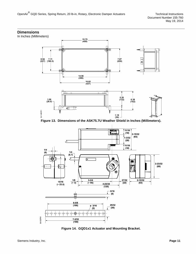
Dimensions In Inches (Millimeters)
Figure 13. Dimensions of the ASK75.7U Weather Shield in Inches (Millimeters).
Figure 14. GQD1x1 Actuator and Mounting Bracket.
Technical Instructions OpenAir® GQD Series, Spring Return, 20 lb-in, Rotary, Electric Damper Actuators Document Number 155-760 May 19, 2014
Information in this publication is based on current specifications. The company reserves the right to make changes in specifications and models as design improvements are introduced. OpenAir is a registered trademark of Siemens Schweiz AG. Product or company names mentioned herein may be the trademarks of their respective owners. © 2014 Siemens Industry, Inc.
Siemens Industry, Inc. Building Technologies Division 1000 Deerfield Parkway Buffalo Grove, IL 60089 USA + 1 847-215-1000
Your feedback is important to us. If you have comments about this document, please send them to [email protected]
Document No. 155-760 Printed in the USA
Page 12
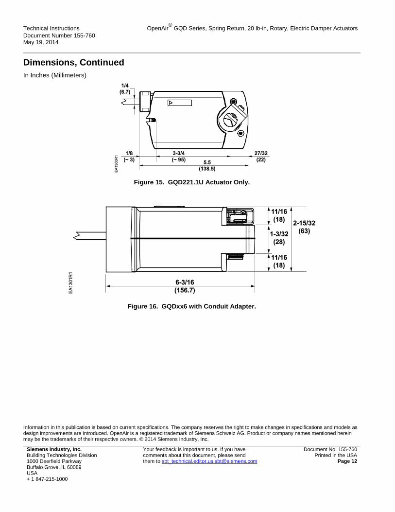
Dimensions, Continued In Inches (Millimeters)
Figure 15. GQD221.1U Actuator Only.
Figure 16. GQDxx6 with Conduit Adapter.