Open Archive Toulouse Archive Ouverte (OATAO) Archive Toulouse Archive Ouverte (OATAO) OATAO is an...
25
Open Archive Toulouse Archive Ouverte (OATAO) OATAO is an open access repository that collects the work of Toulouse researchers and makes it freely available over the web where possible. This is an author-deposited version published in: http://oatao.univ-toulouse.fr/ Eprints ID : 2628 To link this article: http://dx.doi.org/10.1016/j.jmatprotec.2009.02.013 To cite this version: GOUEFFON, Yann. ARURAULT, Laurent. MABRU, Catherine. TONON, Claire. GUIGUE, Pascale. Black anodic coatings for space applications: study of the process parameters, characteristics and mechanical properties. Journal of Materials Processing Technology, vol. 209, n° 11, pp. 5145-5151. ISSN 0924-0136 Any correspondence concerning this service should be sent to the repository administrator: [email protected]
Transcript of Open Archive Toulouse Archive Ouverte (OATAO) Archive Toulouse Archive Ouverte (OATAO) OATAO is an...
Open Archive Toulouse Archive Ouverte (OATAO) OATAO is an open access repository that collects the work of Toulouse researchers and makes it freely available over the web where possible.
This is an author-deposited version published in: http://oatao.univ-toulouse.fr/ Eprints ID: 2628
To link this article: http://dx.doi.org/10.1016/j.jmatprotec.2009.02.013
To cite this version: GOUEFFON, Yann. ARURAULT, Laurent. MABRU, Catherine. TONON, Claire. GUIGUE, Pascale. Black anodic coatings for space applications: study of the process parameters, characteristics and mechanical properties. Journal of Materials Processing Technology, vol. 209, n° 11, pp. 5145-5151. ISSN 0924-0136
Any correspondence concerning this service should be sent to the repository administrator: [email protected]
1
Black anodic coatings for space applications: study of the process parameters,
characteristics and mechanical properties
Yann Goueffon1*, Laurent Arurault2*, Catherine Mabru3, Claire Tonon4, Pascale Guigue1
1 CNES, 18 avenue Edouard Belin, 31401 Toulouse Cedex 9, France.
2 Université de Toulouse, CIRIMAT, UPS/INPT/CNRS, LCMIE, Bat 2R1, 118 route de
Narbonne, 31062 Toulouse Cedex 9, France.
3 Université de Toulouse, ISAE, Département Mécanique des Structures et Matériaux, 10 avenue
Edouard Belin, BP 54032, 31055 Toulouse Cedex 4, France.
4 EADS ASTRIUM Satellites, 31 avenue des Cosmonautes, 31402 Toulouse Cedex 4, France.
* corresponding author :
[email protected] ; phone : 33.561.556.148. ; fax : 33.561.556.163.
Abstract
Black inorganic anodized aluminium alloys are used for managing passive thermal control on
spacecraft and for avoiding stray light in optical equipment. Spalling of these coatings has
sometimes been observed after thermal cycling on 2XXX and 7XXX aluminium alloys. This
phenomenon could generate particulate contamination in satellites and may affect mission
lifetime. In this work, the influences of the four main steps of the process (pretreatments,
sulphuric anodizing, colouring and sealing) on the coating characteristics have been studied for a
7175 T7351 aluminium alloy. The chemical heterogeneity of the coating has been underlined,
2
and its mechanical behaviour observed through crazing. Scratch-testing, used to evaluate coating
adhesion to its substrate, revealed the negative impact of thermal cycling.
Keywords : aluminium, black anodizing, thermal control, microcracking, optical treatment
1. Introduction
Due to the vacuum of space, thermal regulation of satellites is passively managed by radiative
exchange between its external surfaces and the environment. Radiation interactions occur with
the Earth, the moon, deep cold space, the sun and the external parts of the satellite. Satellite
temperatures in a space environment are often passively controlled by thermo-optical properties
of suitable surfaces, ie having convenient solar absorptance (αs) and emittance (ε). Thus, the
utility of black coatings is their αs/ε ratio close to one, which allows passive thermal control of
equipment. Black coatings are also useful to avoid stray light in optical instruments. They can
consist of painted surfaces (McCroskey et al., 2000), metal surfaces (Magdy and Ibrahim, 2006),
oxide layers obtained by micro-arc oxidation (Shrestha et al., 2006) or anodic films coloured
with organic or inorganic dyes (LeVesque et al., 1992; Shih and Huang, 2008]. Black anodic
films (αs > 0.93 ; εn > 0.90) including inorganic dyes are mainly used because of their low cost,
their corrosive and wear resistances during storage, as well as the low risk of contaminating the
spacecraft’s instruments, especially by outgassing. The anodic film is grown by electrochemical
oxidation of the metal surface, without addition of any substances. From this point of view, the
anodic film is not a coating, but a conversion interface tightly bound to the metallic substrate.
The adhesion concept is not considered in this case. However in 2005, an alert from the
European Space Agency (ESA) (ESA Alert, 2005) mentioned many cases of particle detachment
from black anodic films, supported especially on 2XXX and 7XXX type aluminium alloys, after
3
thermal cycling. Such particle pollution is very hazardous for the lifetime of the satellite,
potentially inducing the disturbance of any optical or mechanical mechanisms.
The aim of this research work is to study the operational parameters of the black inorganic
anodizing process, especially the pre-treatment steps, and their impact on the anodic film
characteristics and properties. Adhesion measurements will be particularly discussed.
2. Experimental procedure
The substrate material was the 7175T7351 aluminium alloy. Its chemical composition in weight
percent is: 1.62%Cu, 0.12%Fe, 2.42%Mg, 0.01%Mn, 0.06%Si, 5.75%Zn, 0.041%Ti, 0.21%Cr
and Al the remainder. Moreover, all chemical compounds used were analytical grade. Aqueous
electrolyte solutions were obtained using deionised water.
2.1 Process of elaboration
The preparation of black anodic films including inorganic dyes followed the ESA Standard (ESA
ECSS-Q-70-03A, 2006) for spacecraft design. The process involved four main consecutive steps:
surface pretreatments , anodizing, colouring and sealing.
The alloy sheet (3x20x40mm or 10x20x160mm) was degreased with ethanol and then etched in
Na2CO3 (6.2 g/L) and Na3PO4 (12.5 g/L) aqueous mixed solution (pH = 11) for 5 minutes at
93°C and neutralised (this step is often called desmutting) in aqueous HNO3 (50 %v/v) for 3
minutes at room temperature. The samples were rinsed in distilled water at the end of each step.
The aluminium sheet was then used as anode and a lead plate (3x40x40mm) as counter-electrode
in the electrochemical cell. The anodizing was run for 60 minutes in the galvanostatic mode (Ja =
1.2±0.1 A/dm²) using a sulphuric acid solution (150g/L) thermally regulated at 20°C. The
samples were then immediately rinsed in distilled water.
4
The anodized part was coloured by immersion in two successive baths: firstly for 15 min. in a
purple solution of cobalt acetate (200g/L) regulated at 43 ±2°C, and then for 10 min in a yellow
bath of ammonium hydrosulphide (30g/L) at room temperature. The samples were rinsed in
distilled water after each step to remove the excess solution.
The sealing step occurred for 25 minutes in a bath regulated at 98 ±2°C and made up of nickel
acetate (NiCH3COO, 4H2O) and boric acid (5g/L both).
2.2 Thermal aging
In space, satellites are directly lighted by the sun and then pass into the shadow of Earth, causing
thousands of thermal cycles during their lifetime. To simulate the space environment, the ESA
Standard (ESA ECSS-Q-70-04A, 1999) recommends performing 100 cycles between -100 and
100°C under vacuum (10-5 Pa) with dwells times of 5 minutes minimum and a slope of 10°C per
minute. These conditions were defined for the general case and all kinds of materials and
equipment (from polymers to electronics). In the current paper, we chose to evaluate the samples,
when not otherwise specified, after 10 cycles of -140 to 140°C in a Sun Electronic System EC11
environmental chamber. This could be the maximum range of temperature reached by a satellite
orbiting earth. A nitrogen atmosphere was used first to dissociate vacuum and thermal effects.
Dwells times of 10 minutes and warming/cooling speeds of 10°C/min were used.
2.3. Microscopic and chemical analysis
The meso- and nanostructures of the coatings were observed by field-emission gun scanning
electron microscopy (FEG-SEM) with a JEOL JSM6700F device. Energy Dispersive X-ray
(EDX) spectroscopy analyses were performed on the cross-sections of the samples to identify the
chemical composition inside the film, and especially the location of the dyes.
5
The microstructure of the aluminum substrate was observed by optical microscopy after
metallographic attack for 30 seconds in an acid bath (1%vol. HF, 1.5% HCl, 2.5% HNO3 and
95% of distilled water).
2.4 Characterization and mechanical analysis
Surface roughness was measured before and after pretreatment thanks to a perthometer concept
using a stylus method. Although the profile of the surface was scanned along a line of 5.6mm, the
arithmetic roughness (Ra) was calculated without the first and the last 0.8mm of the profile to
avoid edge effects.
Adhesion measurements were evaluated qualitatively using 180° peel tests with tape strengths of
250 and 500g/cm (ESA ECSS-Q-70-13A, 1999) and quantitatively using a scratch-test device
(CSM Revetest instrument) with a diamond stylus (Rockwell, 200µm radius tip). Scratch tests
were configured with an increasing normal load from 1 to 30N, a loading speed of 30N/min and
an advance speed of 5mm/min. The resulting scratch-print of about 5 mm length was then
observed by SEM to identify the mechanisms of degradation and to determine the corresponding
normal load.
Four-point bending tests were also performed to generate stresses in the coating and then to
observe the possible formation and evolution of cracks. Tests were done on a tensile testing
device (Adamel DY 26 of 100kN) with a distance between supports of 40mm for the face under
compression and 120mm for the face under tension. Samples (10x20x160mm) were observed
with the SEM after loading.
6
3. Results and discussion
The physical and chemical characteristics of the material surface, especially the microstructure
and the porosity, were studied during the different steps of the preparation process with a view to
explaining the final interface properties.
3.1 Microstructure and porosity
3.1.1. The pre-treatment steps
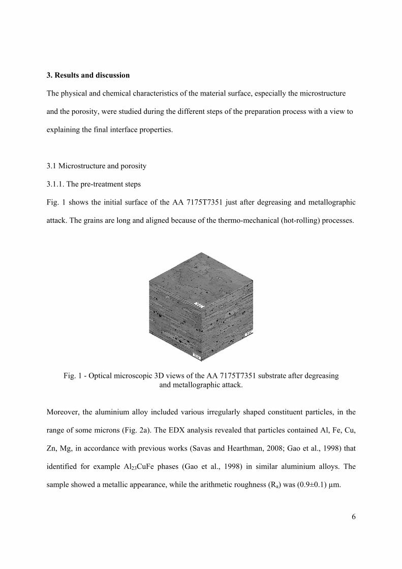
Fig. 1 shows the initial surface of the AA 7175T7351 just after degreasing and metallographic
attack. The grains are long and aligned because of the thermo-mechanical (hot-rolling) processes.
Fig. 1 - Optical microscopic 3D views of the AA 7175T7351 substrate after degreasing and metallographic attack.
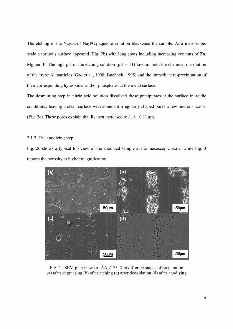
Moreover, the aluminium alloy included various irregularly shaped constituent particles, in the
range of some microns (Fig. 2a). The EDX analysis revealed that particles contained Al, Fe, Cu,
Zn, Mg, in accordance with previous works (Savas and Hearthman, 2008; Gao et al., 1998) that
identified for example Al23CuFe phases (Gao et al., 1998) in similar aluminium alloys. The
sample showed a metallic appearance, while the arithmetic roughness (Ra) was (0.9±0.1) µm.
7
The etching in the Na2CO3 / Na3PO4 aqueous solution blackened the sample. At a mesoscopic
scale a tortuous surface appeared (Fig. 2b) with long spots including increasing contents of Zn,
Mg and P. The high pH of the etching solution (pH = 11) favours both the chemical dissolution
of the “type A” particles (Gao et al., 1998; Buchheit, 1995) and the immediate re-precipitation of
their corresponding hydroxides and/or phosphates at the metal surface.
The desmutting step in nitric acid solution dissolved these precipitates at the surface in acidic
conditions, leaving a clean surface with abundant irregularly shaped pores a few microns across
(Fig. 2c). These pores explain that Ra then increased to (1.8 ±0.1) µm.
3.1.2. The anodizing step
Fig. 2d shows a typical top view of the anodized sample at the mesoscopic scale, while Fig. 3
reports the porosity at higher magnification.
Fig. 2 - SEM plan views of AA 7175T7 at different stages of preparation (a) after degreasing (b) after etching (c) after deoxidation (d) after anodizing
8
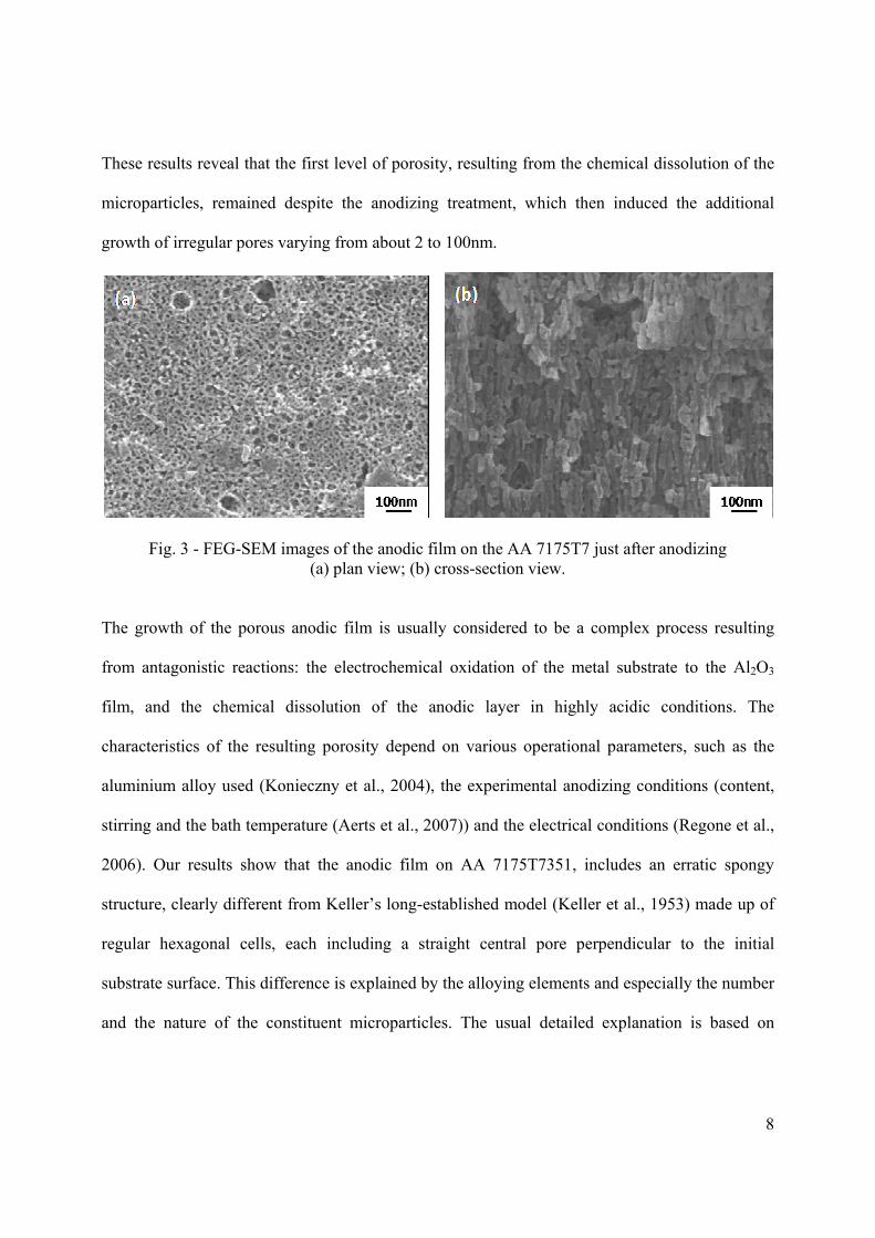
These results reveal that the first level of porosity, resulting from the chemical dissolution of the
microparticles, remained despite the anodizing treatment, which then induced the additional
growth of irregular pores varying from about 2 to 100nm.
Fig. 3 - FEG-SEM images of the anodic film on the AA 7175T7 just after anodizing (a) plan view; (b) cross-section view.
The growth of the porous anodic film is usually considered to be a complex process resulting
from antagonistic reactions: the electrochemical oxidation of the metal substrate to the Al2O3
film, and the chemical dissolution of the anodic layer in highly acidic conditions. The
characteristics of the resulting porosity depend on various operational parameters, such as the
aluminium alloy used (Konieczny et al., 2004), the experimental anodizing conditions (content,
stirring and the bath temperature (Aerts et al., 2007)) and the electrical conditions (Regone et al.,
2006). Our results show that the anodic film on AA 7175T7351, includes an erratic spongy
structure, clearly different from Keller’s long-established model (Keller et al., 1953) made up of
regular hexagonal cells, each including a straight central pore perpendicular to the initial
substrate surface. This difference is explained by the alloying elements and especially the number
and the nature of the constituent microparticles. The usual detailed explanation is based on
9
changes of local current distributions due to potential differences between the metal matrix and
the intermetallic particles.
The thickness of anodic films obtained in sulphuric based electrolytes can vary from 2 to 300µm
(Arurault, 2008). In the conditions used here ([H2SO4] = 150g/L at 20°C, Ja = 1.2 ±0.1 A/dm² for
60 min.), the resulting thickness was about 20µm, i.e. in accordance with the ESA specification
(between 10 and 35µm) for spacecraft design (ESA ECSS-Q-70-03A, 2006).
3.1.3. The sealing step
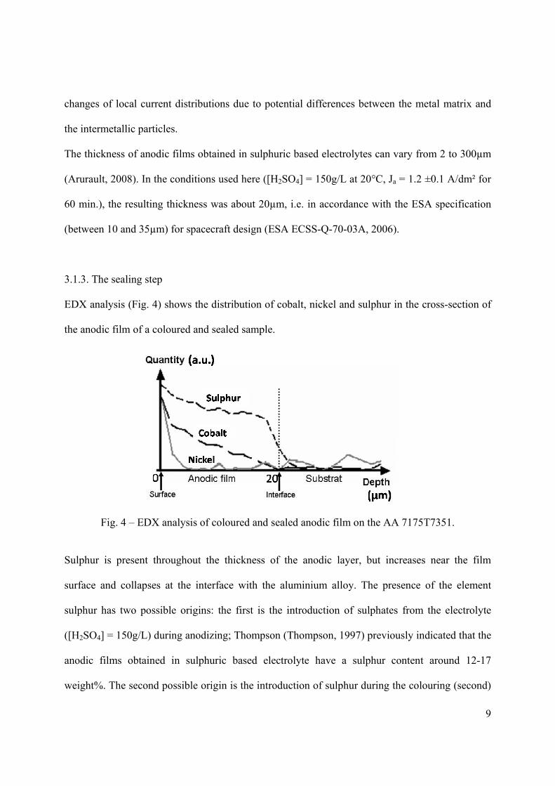
EDX analysis (Fig. 4) shows the distribution of cobalt, nickel and sulphur in the cross-section of
the anodic film of a coloured and sealed sample.
Fig. 4 – EDX analysis of coloured and sealed anodic film on the AA 7175T7351.
Sulphur is present throughout the thickness of the anodic layer, but increases near the film
surface and collapses at the interface with the aluminium alloy. The presence of the element
sulphur has two possible origins: the first is the introduction of sulphates from the electrolyte
([H2SO4] = 150g/L) during anodizing; Thompson (Thompson, 1997) previously indicated that the
anodic films obtained in sulphuric based electrolyte have a sulphur content around 12-17
weight%. The second possible origin is the introduction of sulphur during the colouring (second)
10
step; the increase of sulphur comes from the precipitation of cobalt sulphide taking place inside
the pores during the second step of colouring (Sharma et al., 1997) according to:
Co(CH3COO)2 + (NH4)2S → CoS + 2 CH3COONH4 (1)
This second origin was confirmed by the presence of cobalt concentrated near the surface (Fig.
4), black CoS being formed in the upper part of the pores due to the immersion colouring process.
Nickel was only detected at less than five microns under the surface. This element comes from
the sealing bath but its penetration is limited by the presence of CoS particles in the upper part of
the pores.
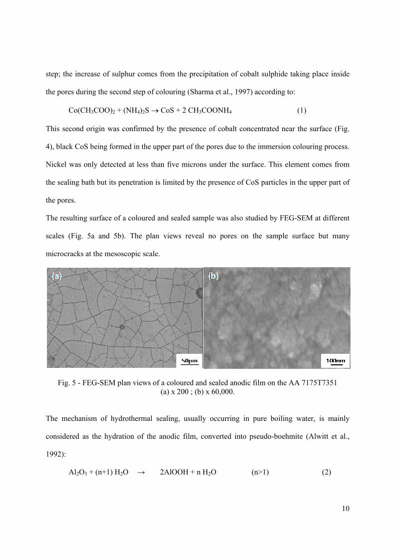
The resulting surface of a coloured and sealed sample was also studied by FEG-SEM at different
scales (Fig. 5a and 5b). The plan views reveal no pores on the sample surface but many
microcracks at the mesoscopic scale.
Fig. 5 - FEG-SEM plan views of a coloured and sealed anodic film on the AA 7175T7351 (a) x 200 ; (b) x 60,000.
The mechanism of hydrothermal sealing, usually occurring in pure boiling water, is mainly
considered as the hydration of the anodic film, converted into pseudo-boehmite (Alwitt et al.,
1992):
Al2O3 + (n+1) H2O → 2AlOOH + n H2O (n>1) (2)
11
In this case, the pore closing results from the expansion of the molar volumes, as well as the
additional precipitation from the nickel acetate. So, the aim of the sealing step is to close the
pores, especially their upper part (Fig. 5a and 5b), to increase efficiency against corrosion and
wear resistance, and protect the dyes against the external atmosphere.
But, the main problem remains understanding the origin of the microcracks and their correlation
with the mechanical properties in general and with the potential flaking of the final coating in
particular.
3.2. Mechanical behaviour
The anodizing process is an electrochemical conversion of the metal surface and does not involve
the addition of external material. That is the reason why anodic films are considered sufficiently
adherent for the usual applications so the concept of adhesion has not been studied much.
The coloured sealed films were studied from the mechanical point of view, before and after
thermal cycling. This cycling simulated the space environment, potentially inducing internal
stress, cracking and ultimately flaking of the coatings.
3.2.1. Preparation process, storage and coating stresses
Whatever the process used to prepare the coatings (PVD, CVD...), they usually have residual
stresses. For example, Alwitt et al. (Alwitt et al., 1992; Alwitt et al., 1993) showed that, before
sealing, non-coloured anodic films on 5657 aluminium alloy anodized in sulphuric acid have
tensile stresses around 30 MPa, depending on the substrate and the process parameters, but not on
the thickness. However, the sealing step seems to be much more critical because the thermal
expansion coefficient is roughly five times greater in the substrate than in the coating (Alwitt et
al., 1992). The sealing bath, regulated at 99°C, caused expansion of the aluminium alloy and
12
subsequent tensile stress in the anodic film. However, once out of the sealing bath, they noted
that residual stresses were largely compressive in the sealed films, increasing with sealing time
and the thickness of the film.
The influence of humidity on residual stresses of the uncoloured films during long-term exposure
to various humidity levels at room temperature were also studied to simulate the effects of space
device storage (Alwitt et al., 1992). Aluminium oxide is indeed hygroscopic, and the amount of
water adsorbed depends on humidity and temperature. At a level of humidity of 0.02 ppm water,
coating stresses are greater than 100MPa tensile while they are between 10 and 30MPa
compressive at ambient humidity. On the contrary, a decrease of humidity dehydrates the sealed
film, contracting the oxide and inducing tensile stresses. McClung et al. (McClung et al., 1992)
particularly noticed that the effects produced by low humidity (0.025ppm) on films grown on the
3XXX and 5XXX series aluminium alloys are reversible and comparable to the effects of a
vacuum (10-6Torr).
3.2.2. Cracking
Due to the difference of thermal expansion coefficient between the anodic film and the substrate,
heating induces tensile stresses in the coating that can lead to cracking if the fracture limit is
reached.
On the anodized 7175 T7351 aluminium alloy, few cracks were observed after the colouring step
performed at 43°C. In all the cases, coloured or not, the samples always cracked just after the
99°C sealing step as shown in Fig. 5a. However, on the 5657 aluminium alloy studied by Alwitt
et al (Alwitt et al., 1992), no crazing was observed after preparation in spite of high tensile
stresses detected during the sealing step. McClung et al. (McClung et al., 1992) studied the
13
crazing of anodic sulphuric films, sealed but not coloured, on 3XXX and 5XXX series aluminium
alloys during heating. They noted that in most cases the first cracks appeared between 100°C and
200°C. But they also noticed that for specimens stored in a damp atmosphere, this critical
temperature decreases to around 70°C (Alwitt et al., 1993). In addition, Alwitt et al. (Alwitt and
McClung, 1993) found that the crazing temperature depends on the aluminium alloy used, and for
a given alloy, on the heat treatment it experienced. Thus, the lower (lower than 100°C) crazing
temperature of anodic films produced in sulphuric acid on the 7175 T7351 alloy compared to
3XXX and 5XXX aluminium alloys can be explained. Indeed, alloying elements, and especially
copper, change the growth mechanisms of the anodic film; thus the shape of the pores as well as
the chemical composition of the anodic films differ from one alloy to another (Garcia-Veraga et
al., 2006; Tsangaraki et al., 2006; Liu et al. 2003; Shimizu et al., 1997), changing the mechanical
characteristics. For example, the interface between the film and its substrate can be modified by
the presence of a layer around 2 nm thick, rich in copper (nearly 40 at. %) (Skeldon et al., 1999).
Finally, in the case of coloured films, the dye content of the pores during sealing must also
change the thermo-mechanical properties of the anodic film.
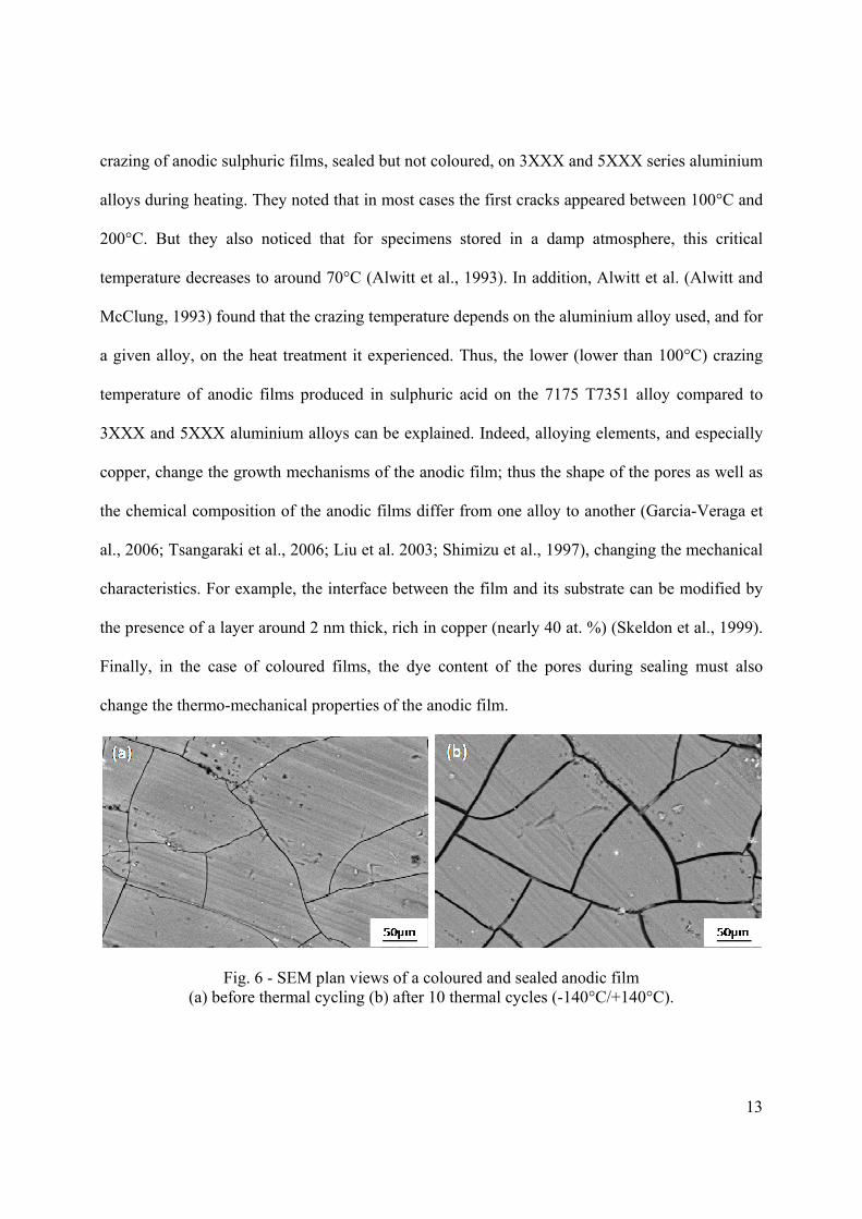
Fig. 6 - SEM plan views of a coloured and sealed anodic film (a) before thermal cycling (b) after 10 thermal cycles (-140°C/+140°C).
14
Fig. 6 reveals that thermal cycling (10 cycles between -140°C/+140°C) had no influence on the
number of cracks but clearly increased the cracks’ width. This can be attributed to a combined
effect of dehydration and thermal differential stresses, higher temperatures (compared with the
sealing temperature) inducing higher tensile stresses in the anodic film. These results are partially
in agreement with similar works (Alwitt et al., 1993) that reported no significant influence of
minimal temperature on the crazing while the maximum temperature was found to be highly
critical. However, Alwit et al. (Alwitt et al., 1993) showed that the number of cracks always
increased as a function of the number of cycles performed on the sample, which is not the case
for the present anodized 7175 T7351 aluminium alloy.
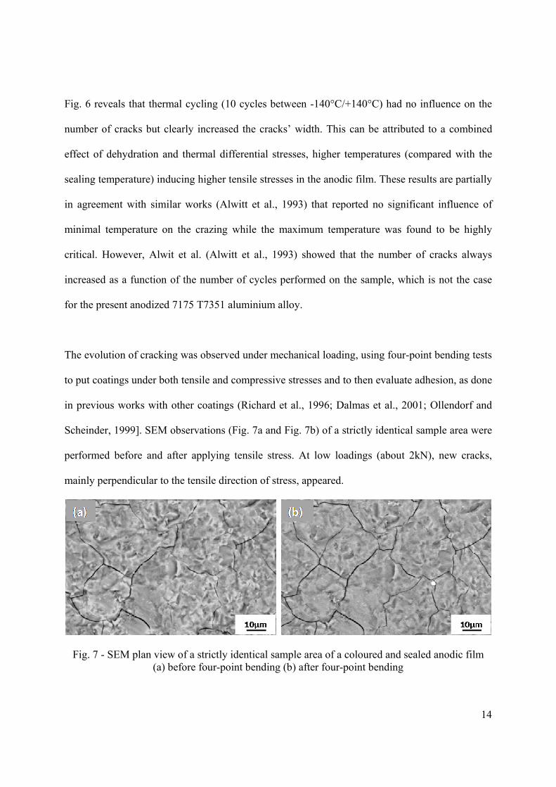
The evolution of cracking was observed under mechanical loading, using four-point bending tests
to put coatings under both tensile and compressive stresses and to then evaluate adhesion, as done
in previous works with other coatings (Richard et al., 1996; Dalmas et al., 2001; Ollendorf and
Scheinder, 1999]. SEM observations (Fig. 7a and Fig. 7b) of a strictly identical sample area were
performed before and after applying tensile stress. At low loadings (about 2kN), new cracks,
mainly perpendicular to the tensile direction of stress, appeared.
Fig. 7 - SEM plan view of a strictly identical sample area of a coloured and sealed anodic film (a) before four-point bending (b) after four-point bending
15
The substrate was then under elastic strain. Higher loadings (about 10kN; plastic strain of the
substrate) did not cause new cracks. However, it is interesting to note that, during bending, when
plastic strains were reached, the face under compressive stress exhibited film flaking whereas the
other (under tensile stresses) did not. In particular, this means that compression stresses induced
crack propagation along the interface leading to particle detachment, i.e. flaking.
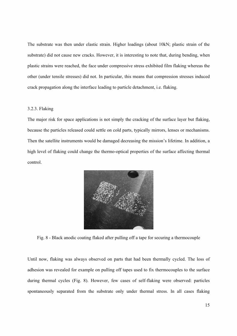
3.2.3. Flaking
The major risk for space applications is not simply the cracking of the surface layer but flaking,
because the particles released could settle on cold parts, typically mirrors, lenses or mechanisms.
Then the satellite instruments would be damaged decreasing the mission’s lifetime. In addition, a
high level of flaking could change the thermo-optical properties of the surface affecting thermal
control.
Fig. 8 - Black anodic coating flaked after pulling off a tape for securing a thermocouple
Until now, flaking was always observed on parts that had been thermally cycled. The loss of
adhesion was revealed for example on pulling off tapes used to fix thermocouples to the surface
during thermal cycles (Fig. 8). However, few cases of self-flaking were observed: particles
spontaneously separated from the substrate only under thermal stress. In all cases flaking
16
occurred on crazed surfaces when the islets delineated by cracks came away. Flaking is thus
directly linked to crazing and was previously observed on aluminium alloys especially in the
2XXX and 7XXX series (ESA Alert, 2005).
Peel tests highlighted the influence of thermal cycling on flaking. These tests revealed that black
anodized parts, thermally cycled five times between -70 and +100°C, showed a “low removal” of
the coating with 250 g/cm tape and “moderate removal” at 500 g/cm. After five cycles between -
140°C and +140°C, the removal of the oxide increased at 250 g/cm, while there was complete
film removal at 500 g/cm and self-flaking was also observed (without any pulling forces applied).
Nevertheless, this test is only qualitative and comparative because the results were strongly
dependent on the type of tape used and on the experimental conditions. Thus, other methods to
evaluate adhesion quantitatively are necessary.
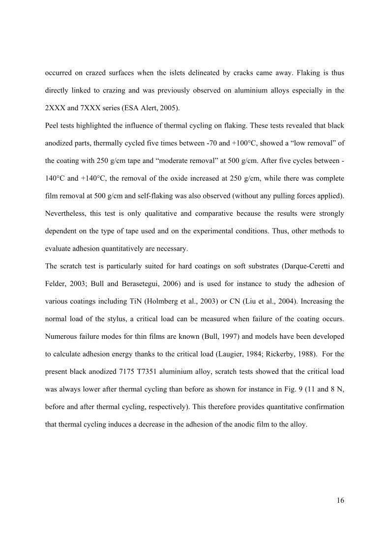
The scratch test is particularly suited for hard coatings on soft substrates (Darque-Ceretti and
Felder, 2003; Bull and Berasetegui, 2006) and is used for instance to study the adhesion of
various coatings including TiN (Holmberg et al., 2003) or CN (Liu et al., 2004). Increasing the
normal load of the stylus, a critical load can be measured when failure of the coating occurs.
Numerous failure modes for thin films are known (Bull, 1997) and models have been developed
to calculate adhesion energy thanks to the critical load (Laugier, 1984; Rickerby, 1988). For the
present black anodized 7175 T7351 aluminium alloy, scratch tests showed that the critical load
was always lower after thermal cycling than before as shown for instance in Fig. 9 (11 and 8 N,
before and after thermal cycling, respectively). This therefore provides quantitative confirmation
that thermal cycling induces a decrease in the adhesion of the anodic film to the alloy.
17
Fig. 9 - Scratch test of a black anodic film followed by SEM (pictures at the top); Acoustic Emission (Left axis) and friction coefficient between stylus and sample (Right Axis)
(a) before thermal cycling (b) after 10 thermal cycles (-140°C/+140°C)
Overall, the decrease of adhesion after thermal cycling can be explained by successive tensile and
compressive loadings of the coating, mainly due to the difference in thermal expansion between
the coating and the substrate. During warming, tensile stresses cause crack propagation across the
film and during cooling, compressive stresses result in cracks along the interface, favouring
flaking and even self-flaking as observed during four-point bending tests. This mechanism of
flaking associated with cooling has already been observed on thermally grown oxides (Chandra et
al., 2007; Baleix et al., 2002; Lours et al., 2008).
18
4. Conclusion
In the current study, we demonstrated that the chemical composition of black inorganic anodic
films is heterogeneous, especially due to the colouring and the sealing steps, which only modify
the external part of the coating. Nevertheless, on AA 7175 T7351, the coating was spongy
throughout its volume due to alloying elements, which modify the mechanical behaviour of the
film compared to other AA series. Thermal cycling enlarges cracks and decreases adhesion of the
coating according to the scratch-test measurements. Anodic films may crack because of two
different phenomena: the difference in the coefficient of thermal expansion between substrate and
coating and the drying of the coating.
Further investigations are currently in progress to evaluate the impact of the anodizing and
colouring parameters on the characteristics of the film and especially its adhesion. In addition, the
roles of humidity and temperature on film cracking during the process and thermal cycling are
currently being studied in order to accurately describe the flaking mechanism.
Acknowledgements
The authors thank Peter Winterton for his helpful comments.
19
References
Aerts, T., Dimogerontakis, Th., De Graeve, I., Fransaer, J., Terryn, H., 2007. Influence of the
anodizing temperature on the porosity and the mechanical properties of the porous anodic film.
Surf. Coat. Technol. 201, 7310-7317.
Alwitt, R.S., McClung, R.C., 1993. Cracking of anodized coatings on aluminium. Plat. and Surf.
Finish. 48-51.
Alwitt, R.S., McClung, R.C., Jacobs, S., 1992. Anodized aluminium coatings for thermal control,
Part I: Coating process and stresses. AIAA-922158-CP, In AAIA Technical papers (A92-31285
12-23) Washington, USA, pp. 39-45.
Alwitt, R.S., Xu, J., McClung, R.C., 1993. Stresses in sulphuric acid anodized coatings on
aluminium. J. Electrochem. Soc. 140, 5, 1241-1246.
Arurault, L., 2008. Pilling-Bedworth ratio of thick anodic aluminium porous films prepared at
high voltages in H2SO4 based electrolyte. Trans. Inst. Met. Finish. 86, 1, 51-54.
Baleix, S., Barnhart, G., Lours, P., 2002. Oxidation and oxide spallation of heat resistant cast
steels for superplastic forming dies. Mater. Sci. Eng. 327, 155-166.
Buchheit, R.G., 1995. A Compilation of Corrosion Potentials Reported for Intermetallic Phases in
Aluminum Alloy. J. Electrochem. Soc.142, 3394-3396.
Bull, S.J., 1997. Failure mode maps in the thin film scratch adhesion test. Tribol. Int. 30, 7, 491-
498.
Bull, S.J., Berasetegui, E.G., 2006. Overview of the potential of quantitative coating adhesion
measurement by scratch testing. Tribol. Int. 39, 99-114.
Chandra-Ambhorn, S., Wouters, Y., Antoni, L., Toscan, F., Galerie, A., 2007. Adhesion of oxide
scales grown on ferritic stainless steels in solid oxide fuel cells temperature and atmosphere
conditions. J. Power Sourc. 171, 688–695.
20
Dalmas, D., Benmedakhene, S., Richard, C., Abdelouahed, L., Béranger, G., Grégoire, T., 2001.
Characterization of adherence and cracking within coated materials by an acoustic emission
method : application to a WC-Co coating on a steel substrate, Surf. Chem. Catal. 4, 345-350.
Darque-Ceretti, E., Felder, E., 2003. Adhésion – Adhérence. CNRS Editions, Paris, pp 251-264.
ESA Alert, EA-2005-MEP-02-B. PSS-01-703 Inadequate for 2XXX and 7XXX alloys, February
2005. http://alerts.esa.int/
ESA ECSS-Q-70-03A, Black-anodizing of metals with inorganic dyes, April 2006.
http://www.ecss.nl (Update of the PSS-01-703)
ESA ECSS-Q-70-04A, Thermal cycling test for the screening of space materials and processes,
October 1999. http://www.ecss.nl
ESA ECSS-Q-70-13A, Measurement of the peel and pull-off strength of coatings and finishes
using pressure-sensitive tapes, October 1999. http://www.ecss.nl
Gao, M., Feng, C.R., Wei, R.P., 1998. An analytical electron microscopy study of constituent
particles in commercial 7075-T6 and 2024-T3 alloys. Metall. Mater. Trans. 29, 4, 1145-1151.
Garcia-Vergara, S.J., El Khazmi, K., Skeldon, P., Thompson, G.E., 2006. Influence of copper on
the morphology of porous anodic alumina. Corrosion Sci. 48, 2937-2946.
Holmberg, K., Laukkanen, A., Ronkainen, H., Wallin, K., Varjus, S., 2003. A mode l for stresses,
crack generation and fracture toughness calculation in scratched TiN-coated steel surfaces. Wear.
254, 278-291.
Keller, F., Hunter, M.S., Robinson, D.L., 1953. Structural Features of Oxide Coatings on
Aluminum. J. Electrochem. Soc. 100, 9, 411-419.
Konieczny, J., Dobrzanski, L.A., Labisz, K., Duszczyk, J., 2004, The influence of cast method
and anodizing parameters on structure and layer thickness of aluminium alloys. J. Mater. Process.
Tech. 157-158, 718-723.
21
Laugier, M. T., 1984. An energy approach to the adhesion of coatings using the scratch test. Thin
Solid Films. 117, 4, 243-249.
LeVesque, R., Ho, M., Vickers, B., Babel, H., Pard, A., 1992. Black anodize as a thermal control
coating for space station freedom. AIAA-92-2160-CP, In AAIA Technical papers (A92-31285
12-23) Washington, USA, pp. 56-65.
Liu, Y., Sultan, E.A., Koroleva, E.V., Skeldon, P., Thompson, G.E., Zhou, X., Shimizu, K.,
Habazaki, H., 2003. Grain orientation effects on copper enrichment and oxygen generation
during anodizing of al-1at.%Cu alloy. Corrosion Sci. 45, 789-797.
Liu, Z., Sun, J., Wu, J.D., Wang, P.N., Shen, W., 2004. Determination of adhesion energy of
CNx thin film on silicon from micro-scratch testing. Tribol. Trans. 47, 130-137.
Lours, P., Sniezewski, J., Le Maoult, Y., Pieraggi, B., 2008. Direct observations and analysis of
the spallation of alumina scales grown on PM2000 alloy. Mater. Sci. Eng. 480, 40-48.
Magdy, A., Ibrahim, M., 2006. Black nickel electrodeposition from a modified Watts bath. J.
Appl. Electrochem. 36, 295-301.
Mc Clung, R.C., Alwitt, R.S., Jacobs, S., 1992. Anodized aluminium coatings for thermal
control, Part II: Environmental effects and cracking. AIAA-92-2159-CP, In AAIA Technical
papers (A92-31285 12-23) Washington, USA, pp. 46-55.
McCroskey, D.M., Abell, G.C., Chidester, M.H., 2000. Aeroglaze Z306 black paint for cryogenic
telescope use: outgassing and water vapor regain. In: SPIE The International Society for Optical
Engineering (Ed.) Proceeding SPIE, 4096, pp.119-128.
Ollendorf, H., Schneider, D., 1999. A comparative study of adhesion test methods for hard
coatings. Surf. Coat. Technol. 113, 86-102.
Regone, N.N., Freire, C.M.A., Ballester, M., 2006. Al-based anodic films structure observation
using field emission gun scanning electron microscopy. J. Mater. Process. Tech. 172, 146-151.
22
Richard, C.S., Béranger, G., Lu J., Flavenot, J.F., Grégoire, T., 1996. Four-point bending tests of
thermally produced Wc-Co coatings. Surf. Coat. Technol. 78, 284-294.
Rickerby, D. S., 1988. A review of the methods for the measurement of coating-substrate
adhesion. Surf. Coat. Technol. 36, 1-2, 541-55.
Savas, T.P., Earthman, J.C., 2008. Surface characterization of 7075-T73 aluminium exposed to
anodizing pretreatment solutions. J. Mat. Eng. Perform. (under press) DOI: 10.1007/s11665-008-
9219-3.
Sharma, A.K., Bhojraj, H., Kaila, V.K., Narayanamurthy, H., 1997. Anodizing and inorganic
black coloring of aluminium alloys for space applications. Met. Finish. 95, 12, 14-20.
Shih, H-H., Huang, Y-C., 2008. Study of the black electrolytic coloring of anodized aluminium in
cupric sulfate. J. Mater. Process. Tech. (under press) DOI :10 :1016/j.jmatprotec.2007.12.119.
Shimizu, K., Kobayashi, K., Thompson, G.E., Skeldon, P., Wood, G.C., 1997. The influence of
θ’ precipitates on the anodizing behaviour of binary Al-Cu alloys. Corrosion Sci. 39, 2, 281-284.
Shrestha, S., Shashkov, P., Dunn, B.D., 2006. Microstructural and thermo-optical properties of
black Keronite PEO coating on aluminium alloy AA7075 for spacecraft materials applications.
In: Proceedings of ISMSE & ICPMSE, SP-616, ESA Publication Division, Collioure, France, pp.
s1.5.1-9.
Skeldon, P., Thompson, G.E., Wood, G.C., Zhou, X., Habazaki, H., Shimizu, K., 1999.
Interraction of alloying elements during anodizing of dilute Al-Au-Cu and Al-W-Zn alloys and
consequences for film growth. Corrosion Sci. 41, 291-304.
Thompson, G.E., 1997. Porous anodic alumina: fabrication, characterization and applications.
Thin Solid Films. 297, 1-2, 192-201.
23
Tsangaraki-Kaplanoglou, I., Theohari, S., Dimogerontakis, Th., Wang, Y.M., Kuo, H.H., Kia, S.,
2006. Effect of alloy types on the anodizing process of aluminium. Surf. Coat. Technol. 200,
2634-2641.
24
Figures Captions
Fig. 1 - Optical microscopic 3D views of the AA 7175T7351 substrate after degreasing and metallographic attack. Fig. 2 - SEM plan views of AA 7175T7 at different stages of preparation (a) after degreasing (b) after etching (c) after deoxidation (d) after anodizing Fig. 3 - FEG-SEM images of the anodic film on the AA 7175T7 just after anodizing (a) plan view; (b) cross-section view. Fig. 4 – EDX analysis of coloured and sealed anodic film on the AA 7175T7351. Fig. 5 - FEG-SEM plan views of a coloured and sealed anodic film on the AA 7175T7351 (a) x 200 ; (b) x 60,000. Fig. 6 - SEM plan views of a coloured and sealed anodic film (a) before thermal cycling (b) after 10 thermal cycles (-140°C/+140°C). Fig. 7 - SEM plan view of a strictly identical sample area of a coloured and sealed anodic film (a) before four-point bending (b) after four-point bending Fig. 8 - Black anodic coating flaked after pulling off a tape for securing a thermocouple Fig. 9 - Scratch test of a black anodic film followed by SEM (pictures at the top); Acoustic Emission (Left axis) and friction coefficient between stylus and sample (Right Axis) (a) before thermal cycling (b) after 10 thermal cycles (-140°C/+140°C)