ONG ppt - Earth Protection.ppt - ABB Groupfile/ONG+ppt+-+Earth+Protection.pdf · Ong Peck Seng, LP...
86
Ong Peck Seng, LP Marketing, Electric Power System Seminar, 5thJuly2011 Power System Earth Protection Power System Earth Protection Protects Your Life, Protects Your Property © ABB Group July 12, 2011 | Slide 1
Transcript of ONG ppt - Earth Protection.ppt - ABB Groupfile/ONG+ppt+-+Earth+Protection.pdf · Ong Peck Seng, LP...

Ong Peck Seng, LP Marketing, Electric Power System Seminar, 5thJuly2011
Power System Earth ProtectionPower System Earth ProtectionProtects Your Life, Protects Your Property
© ABB Group July 12, 2011 | Slide 1

Electric Power System SeminarNote of this Power Point
We would like to say a big thank you for your time attending our seminar on 5thJuly2011 at ABB premises.
This Power Point is meant for your reference only.
Please contact us if you need to verify the data or application used.
The contents of this PPT is mainly extracting from our 3rd Technical Application Paper, please refer to the booklet for more detail.
Distribution system and protection against indirect contact and earth fault.
This PPT contain 88 pages due to time constrain we are only ableThis PPT contain 88 pages, due to time constrain, we are only able to present only 60 slides, the rest of the slides are for your info, please feel free to contact for more questions.
Hope to see you in our future programs.
Thanks

Electric Power System SeminarProgram
Agenda1.00 pm Registration1.15 pm Welcome1.30 pm Earth leakage and earth
fault protection of electricalBy Ong Peck Seng, AVP Marketing Low Voltagefault protection of electrical
distribution system. AVP Marketing, Low Voltage Products Division
3 00 p m Break and Q&A3.00 p.m. Break and Q&A3.30 p.m. SS and IEC Standard
requirements for over-By Koh Nguang Siah, Product Marketing Manager,
current and earth leakage protection devices.
Low Voltage Product Division
4 30 Th i t f th B K h N Si h4.30 p.m. The requirement for earth leakage relay (ELR) according to IEC 60947-2
By Koh Nguang Siah, Product Marketing Manager, Low Voltage Product
© ABB Group July 12, 2011 | Slide 3
Annex M Division
Earth leakage and earth faultTopic 1
Earth leakage and earth fault protection of electrical distribution system.

Earth leakage and earth fault protection of electrical distribution system. Contents
Why Earthing System
I di t t t d l t ti Indirect contact and people protection
Indirect contact and property protection
Earth fault protection
© ABB Group July 12, 2011 | Slide 5

L1L1L2
N
L3
Earthing (Grounding) SystemEarthing (Grounding) System

Earthing SystemWhy Earthing
Have you ever wander if the neutral of the power transformer is not connected to earth (ground), the risk of being electrocuted will be elaminated?
The answer is not so straight forward, please see few demo as follow:
1.) Isolated earthing
2.) Vertual earth due to stray capacitance
3.) One of the “Phase“ grounded
© ABB Group July 12, 2011 | Slide 7

Earthing System Demo 1Isolated Earthing
L1L2
N
L3
Neutral not connected to earth
Isolated earthing
Neutral not connected to earth
Neutral point of transformer not connected to earth (IT System)
Q, will I get a shock if I touch any one of the Line (L1, L2, or L3) since there is no return path.
A, Only if the out going cables are very short and no virtual earth is formed in the system
© ABB Group July 12, 2011 | Slide 8
system.

Earthing System Demo 2Virtual Earth
L1L2
N
L3
Virtual Earth will still be formed due to stray capacitence
Q, Will I in danger if I touch the Line (L1, L2 or L3)
A, Depends on the stray capacitence, leakage current various.
© ABB Group July 12, 2011 | Slide 9

Earthing System Demo 3One Phase Shorted to Earth
L1L2
N
L3
Q: What happen if one phase shorted to earth?
A: 1.) There will not be having a fault.
2.) The other two phases (in this case L1 & L2) will have line voltage with respect to earth, in this demo, will be 433Volts. Neutral to earth will be about 250 Volts.
© ABB Group July 12, 2011 | Slide 10

Earthing System One More Reasons to Earth the System
Loads
Weak point may be damage if no end is earthed
Strong disturbance appeared due to switching or lightning, extra high voltage surge refer to earth (common mode) will
p y g
extra high voltage surge refer to earth (common mode) will travel towards both ends, weak insulation point may be damaged.
Earthing of Neutral point will minimized this problem, surge arrestor is also advise to install at the load end.
© ABB Group July 12, 2011 | Slide 11

Earthing System Neutral Earthed
L1L2
eake
r h n
N
ircui
t Bre
ith E
arth
rote
ctio
n
L3
Neutral solidly earthed
Ci
wi
Pr
To minimze the above mentioned phenomenon, earthing of neutral is compulsary except for some special requirement like IT system
Neutral solidly earthed
except for some special requirement like IT system.
© ABB Group July 12, 2011 | Slide 12

Earthing SystemEarthing for System Protection
Uo
Un
At least two main reasons amount many others are:At least two main reasons amount many others are:
1.) Drainage of excessive high surge volatge, especially the common mode disturbancesmode disturbances
2.) Preventing prolong high voltage of any phase become Un against earth instead of Uo as per normal working condition
© ABB Group July 12, 2011 | Slide 13
p g
Any way the virtual earth will still formed for large installation

Indirect Contact and PeopleIndirect Contact and People Protection

Indirect contact protection
Protection against Contact:
People Protection

IEC 60479-1
Effects of current on human beings and livestock
SS 97IEC 61008

Impedance of the human body

Internal impedances of the human body
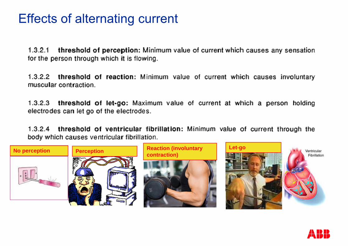
Effects of alternating current
Let-goReaction (involuntary contraction)PerceptionNo perception
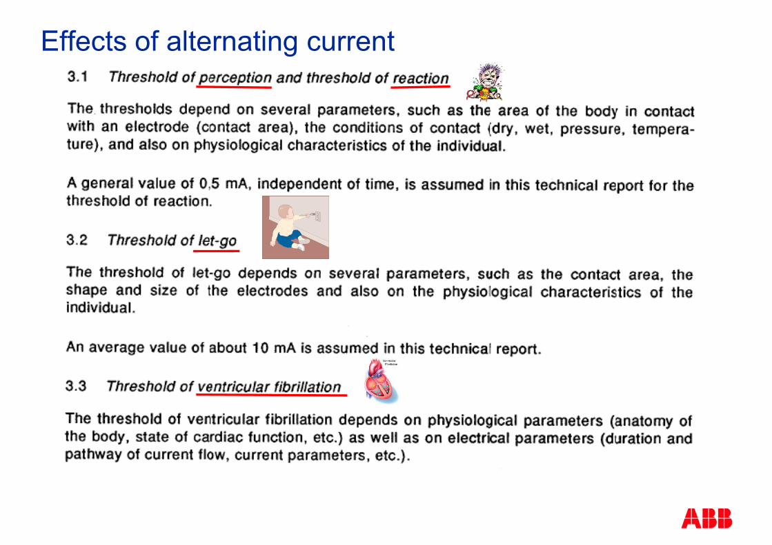
Effects of alternating current

Physiological effects
IEC describes as follow the current effects:IEC describes as follow the current effects:
TTimeime ms ms Fibrillation Tetanization Perception
1000
5000
2000
No reactionNo harmful physiological effectReversible pathological effects
1 2 3
50%> 50%
1000
500
Reversible pathological effectsFibrillation risk greater than50%
3
4 5%
100
200
50%2 1 3 4
50
20
0,1 0,2 1 0,5 2 5 10 20 50 100 200 500 1000 2000 5000 10000 10
mA mA

Earthing System Demo 4Physiological Effect
Isolation Transformer Below 50VoltBelow 500 µA
No reactionBelow 500 µANo reaction
Volt Meter
µAmpMeter
VariacTransformer
MeterMeter
© ABB Group July 12, 2011 | Slide 22

Earthing System Direct Contact
© ABB Group July 12, 2011 | Slide 23

Earthing SystemSelectivity
10mA 30mA 100mA Human Life Protection protection against 10mA, 30mA, 100mA, Human Life Protection, protection against indirect contact by the automatic disconnection of supply
300mA 500mA 1000mA Fire Protection 300mA, 500mA, 1000mA, Fire Protection
Higher that the above value is consider earth fault.
© ABB Group July 12, 2011 | Slide 24

Earthing System – Auto-disconnection of supplyRCD, RCCB, ELCB, RCBO, ELR, EFR
•RCD, RCCB, ELCB, •Voltage independent type, operating based on induced secondary current. Voltage dependent RCD is equipped with an amplification circuit•Voltage dependent RCD is equipped with an amplification circuit.
ifier
fier
Am
pl
Am
plif
•RCBO – A device with the combination of RCD and Circuit Breaker•ELR/EFR, A measurement device giving output contact to trip the shunt trip coil of a circuit breaker
© ABB Group July 12, 2011 | Slide 25
the shunt trip coil of a circuit breaker

Earthing SystemSelectivity 10mA
10mA:
Sensitive human life protection Sensitive human life protection Hospital Kindergarten etc Kindergarten, etc
Final distribution circuit for better discrimination
IdId 30mA
Must be voltage independent
Id t = 0 sec.
Can be voltage
Id Id IdId 10mAt = 0 sec.
Id 10mAt = 0 sec.
Id 10mAt = 0 sec.
Can be voltage dependent
© ABB Group July 12, 2011 | Slide 26
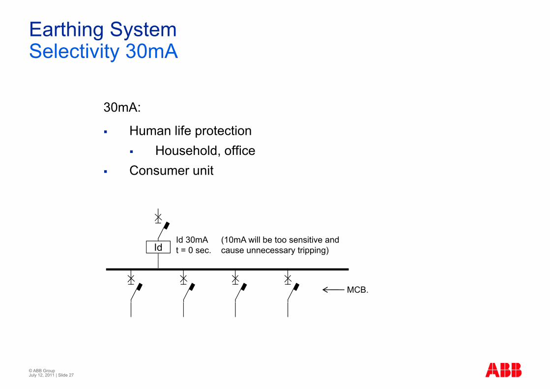
Earthing SystemSelectivity 30mA
30mA:
Human life protection Human life protection Household, office
Consumer unit Consumer unit
IdId 30mAt = 0 sec.
(10mA will be too sensitive and cause unnecessary tripping)
MCB.
© ABB Group July 12, 2011 | Slide 27

Earthing SystemSelectivity 100mA
100mA:
Human life protection and propoer discrimination Human life protection and propoer discrimination Sub-board circuit
IdId 100mAt = 0 sec.
(30mA will be too sensitive and cause unnecessary tripping)y pp g)
IdId 10mAt = 0 sec. Id
Id 30mAt = 0 sec.Id
Id 30mAt = 0 sec.
© ABB Group July 12, 2011 | Slide 28

Earthing SystemPulsation DC Leakage
Electronics circuit with Rectifiers or PV panel, generating DC source volatge, standard AC types of RCCB or RCBO may not be sensitive g yp yenought to trip at the designed value, A and B types are available.
IdA type.Id 100mAt = 0 sec.
(to cater for electronic / loads and circuitry )
IdA typeId 30mA Id
A typeId 30mA
t = 0 sec. t = 0 sec.
© ABB Group July 12, 2011 | Slide 29
Electronics Circuitry

Earthing SystemPulsation DC Leakage – Demo 5
Isolation Transformer
R = 150ohmVariacTransformer
ACT
mAR = 150ohm
Fluke 43BId
Type
A
43B
Id
AType
© ABB Group July 12, 2011 | Slide 30

Indirect Contact and PropertyIndirect Contact and Property Protection

Earthing SystemSelectivity 300mA
300mA:
P t t ti ( i t fi ) Property protection (against fire)
Id 500mA(discrimination with down stream 300mA))
Lik l t fiIdId 30mAt = 0 sec. G
Id 300mAt = x sec.
Likely to cause fire if the leakage current is morecurrent is more than 300mA
© ABB Group July 12, 2011 | Slide 32

Earthing SystemLeakage more than 300mA – Demo 6
300mA:
P t t ti ( i t fi ) Property protection (against fire)
Id500mA (discrimination with down stream
300mA))
Lik l t fiIdId 30mAt = 0 sec. Id
Id 300mAt = x sec.
Likely to cause fire if the leakage current is more
Load
current is more than 300mA
© ABB Group July 12, 2011 | Slide 33

Earthing SystemEarth Leakage or Earth Fault
Earth Leakage Earth FaultToroid built-in the g•Low current•Measuring using Toroid
•High current•Measuring using CT
RCD
Toroid for externalToroid for external Relay

Earthing SystemEarth Fault
10 to 20% of In or 120A which ever is lower
10 to 20% or 120A which ever is lower
EFR
which ever is lowert = 2 x sec.
EFR
10 t 20% 80AEFR
10 to 20% or 80A which ever is lowert = x sec.
EFR
t x sec.
IGId 30mAt = 0 sec.
© ABB Group July 12, 2011 | Slide 35
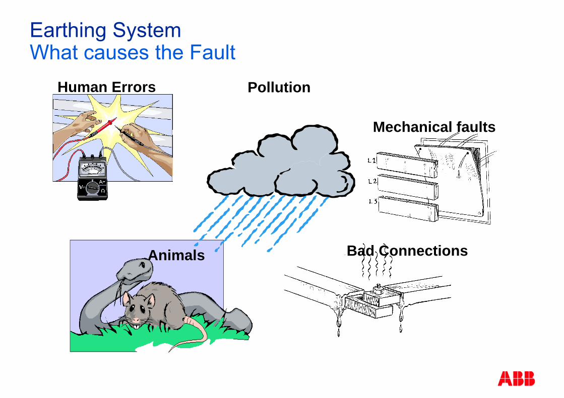
Earthing System
Human Errors Pollution
What causes the Fault
Mechanical faults
Human Errors Pollution
Bad ConnectionsAnimals
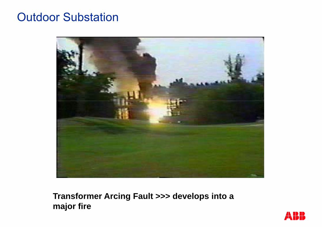
Outdoor Substation
Transformer Arcing Fault >>> develops into a major fire

Earthing SystemEarthing System

Earthing Systems
Letter code meanings:g
1st letter : situation of the electrical system in yrelation to the earth
direct connection of one point to earthT
orall live parts isolated from earthI
connection of one point to earth throughout an impedancethroughout an impedance

Earthing Systems
Letter code meanings:
2nd letter : situation of the exposed-conductive-parts of the installation in relation to the earth
T direct electrical connection ofT direct electrical connection of exposed-conductive-parts to earth
Ndirect electrical connection of the exposed-conductive-parts t th th d i t f th tto the earthed point of the power systemIn a.c. systems, the earthed point of the powersystem is normally the neutral point

Earthing Systems
Letter code meanings:Letter code meanings:
S bseq ent letter (if an ) N and PE cond ctorsSubsequent letter (if any): N and PE conductors arrangement
S N and PE conductors separated
N and PE conductors combined in a
Cin asingle conductor (PEN conductor)
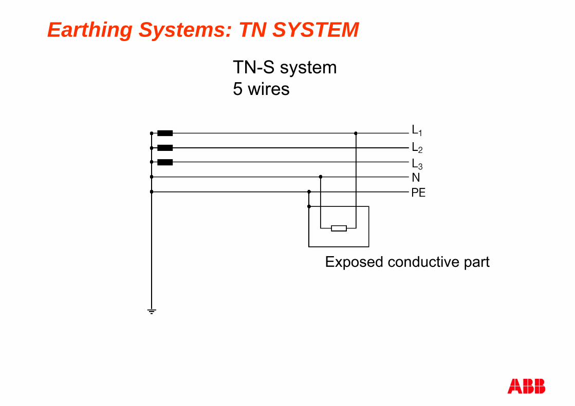
Earthing Systems: TN SYSTEMTN-S system5 wires5 wires
Exposed conductive part

Earthing Systems: TN SYSTEMTN-S system4 wires4 wires
Exposed conductive part

Earthing Systems: TN SYSTEMTN-C system
Exposed conductive part
Not allowed in Singapore

Earthing Systems: TN SYSTEMTN-C-S system
Not allowed in Singapore

Earthing Systems: TT SYSTEM
Exposed conductive part

Earthing Systems: IT SYSTEMIT system
Exposed conductive partp p
Earthing Systems: IT SYSTEM
Power system: no connection between live parts and earthno connection between live parts and earth
orconnection by high value impedance
Electrical installations:d d ti t t d
co ect o by g a ue peda ce
exposed conductive parts connected (independently or collectively) to earth
Earthing Systems: IT SYSTEM
Typical applications:i d t i l tiliti i t ll ti ( i ll h i l industrial or utilities installations (especially chemical, petrochemical and telecommunications) for which a very high level of service continuity is required;very high level of service continuity is required; installations for IT apparatuses fed by UPS
Small values of short circuit currents to earth (1st fault),typically 1 to 10 A (0 1A/km cable);typically 1 to 10 A (0.1A/km cable);
Medium-high values of short circuit currents to earth (2nd Medium high values of short circuit currents to earth (2fault)
It is strongly recommended not to distribute the N-conductorconductor
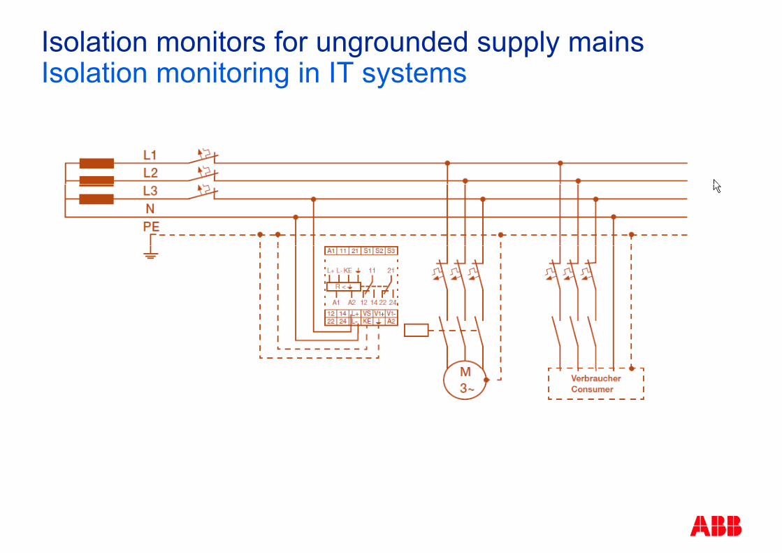
Isolation monitors for ungrounded supply mainsIsolation monitoring in IT systems

Proposed solutionProposed solution

Earthing System – People ProtectionEnsure Good Selectivity for 30mA and 10mA
30mA for 3 units of 10mA
Human life protection and propoer discrimination Human life protection and propoer discrimination Consumer units e.g.
IdId 30mAt = 0 sec.
(10mA will be too sensitive and cause unnecessary tripping)y pp g)
IdId 10mAt = 0 sec. Id
Id 10mAt = 0 sec. Id
Id 10mAt = 0 sec.
© ABB Group July 12, 2011 | Slide 52
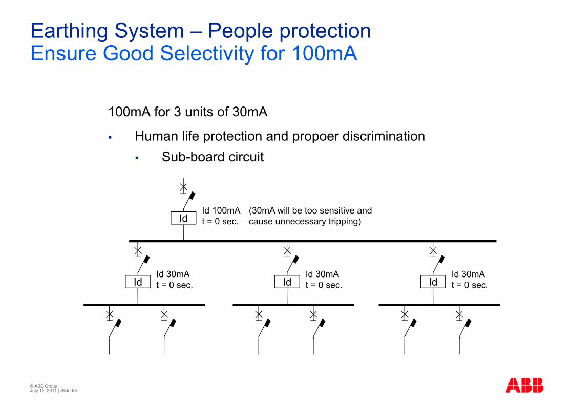
Earthing System – People protectionEnsure Good Selectivity for 100mA
100mA for 3 units of 30mA
Human life protection and propoer discrimination Human life protection and propoer discrimination Sub-board circuit
IdId 100mAt = 0 sec.
(30mA will be too sensitive and cause unnecessary tripping)y pp g)
IdId 30mAt = 0 sec. Id
Id 30mAt = 0 sec. Id
Id 30mAt = 0 sec.
© ABB Group July 12, 2011 | Slide 53

Earthing System – Fire ProtectionMain and Feeder Circuit
10 to 20% or 120A which ever is lower with delay time at the main
Mian incoming Mian incoming
EFR
LSIG
External RelayEFR
10 t 20% 80A
y
EFR10 to 20% or 80A which ever is lowert = x sec.
EFR
t x sec.
IGId 30mAt = 0 sec. Depends on the
typr loads© ABB Group July 12, 2011 | Slide 54
typr loads

Earthing System – Motor ProtectionMain and Feeder Circuit
Advisible for the motor motor circuit to add ELR or EFR
EFR
LSIG
External RelayEFR
5 to 10% of Int = x sec
y
EFR
t = x sec.EFR
IGId 30mAt = 0 sec. UMC
© ABB Group July 12, 2011 | Slide 55

Earthing System – VSDMain and Feeder Circuit
Advisible for all VSD earth protection to be adjusted 300mA or more
ELR
≥ 1000mA
ELR
≥ 300mAA type prefered
EFR
A type preferedRCD
EMC
IGId 30mAt = 0 sec.
Filter
VSD
M
© ABB Group July 12, 2011 | Slide 56
MM
Inherent leakage current

Earthing System – Total SolutionsRCD, RCCB, ELCB, RCBO, ELR, EFR
© ABB Group July 12, 2011 | Slide 57

Earthing System – Total SolutionsAvoid Nuisance Tripping
Select correct type tested product with relevant standards especially the EMC compliances.p
Consider using auto-reclosurer.
© ABB Group July 12, 2011 | Slide 58

© ABB Group July 12, 2011 | Slide 59

Additional InfoAdditional Info

Protection of lines
Protection against indirect contactVerification about the Max Length protected against indirectg p gcontact for TN systems with neutral conductor not distributed
8.0 SUL
minmax 25.1
8.0ISUL
U = rated voltage of the system (V)
Imin = minimum short circuit current value (A)min ( )
S = Phase conductor cross-section (mm2)
= conductor resistivity @ 20 °C (mm2/m) [0 018-copper/0 027- conductor resistivity @ 20 C ( mm /m) [0.018 copper/0.027aluminium]
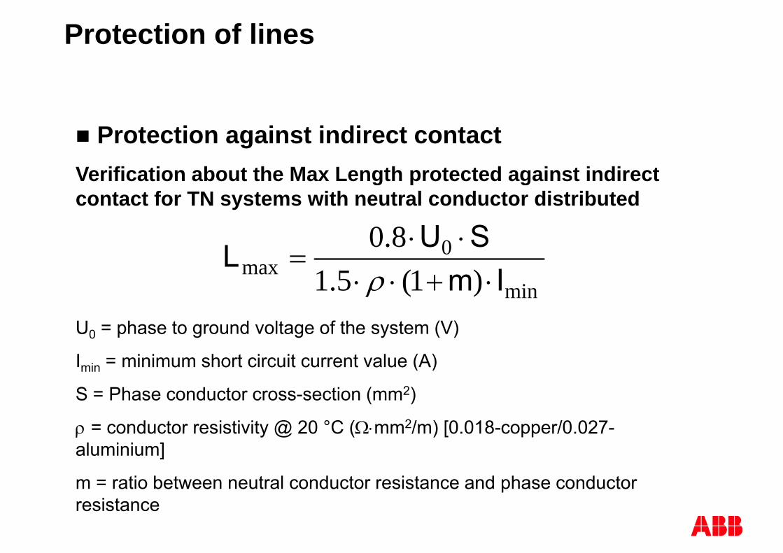
Protection of lines
Protection against indirect contactVerification about the Max Length protected against indirect g p gcontact for TN systems with neutral conductor distributed
08.0 SUL
min
0max )1(5.1
8.0Im
SUL
U0 = phase to ground voltage of the system (V)
Imin = minimum short circuit current value (A)min ( )
S = Phase conductor cross-section (mm2)
= conductor resistivity @ 20 °C (mm2/m) [0 018-copper/0 027- conductor resistivity @ 20 C ( mm /m) [0.018 copper/0.027aluminium]
m = ratio between neutral conductor resistance and phase conductor presistance

Protection of lines
Protection against indirect contact
The protection of the cable is assured if:The protection of the cable is assured if:
32.1min II
Magnetic threshold
Max magnetic threshold tolerance

Indirect Contacts TT system
Fault current in TT
Low level currentLow level current
Ik = U0 / Rt
where:where:
• Rt is the total resistance, equal to the sum of the earth electrode (RA) andsum of the earth electrode (RA) and the protective conductor for the exposed conductive parts [Ω];p p [ ];
• U0 is the rated voltage between phase and groundp g

Max admissible voltage in TT system
R 50
MV/LV Transformer
IdRT Transformer
RT Ground resistance
Id Tripping differentialcurrent- G or S typeG or S type- Max delay 1 secdistribution circ.
50 V normal environment50 V normal environment25 V shipyard,
ambulatory, stableRRTTRRNN
TT

TT Sistems
Indirect protection normally done with SecuritySecurity
Groundresistance
Nominal currents
normally done with a RCD + a coordination with G d i t
yy
30mAresistance
R t
currents In
5 mA 10 k
Ground resistance 30mA
5 mA 10 k10 mA 5 k30 mA 1666
100 A 500
+100 mA 500 300 mA 166 500 mA 100 ++ T
1 A 50 3 A 16,6 5 A 10
++ DDADDARRTTDDA
T
5 A 10 10 A 5 20 A 2,5
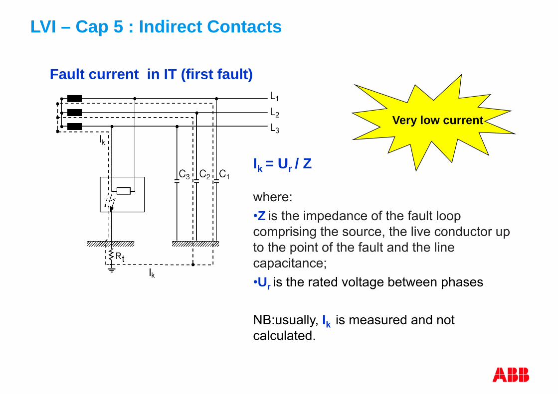
LVI – Cap 5 : Indirect Contacts
Fault current in IT (first fault)
Very low current
Ik = Ur / Z
where:•Z is the impedance of the fault loopZ is the impedance of the fault loop comprising the source, the live conductor up to the point of the fault and the line capacitance;capacitance;•Ur is the rated voltage between phases
NB:usually, Ik is measured and not calculated.

LVI – Cap 5 : Indirect Contacts
Fault current in IT (second fault, IT ->TT)
low current level
Ik = Ur / Rt
where:
•Rt is the total resistance, equal to the sum of the earth electrode (RA) and the protective conductor for the exposed conductive parts [Ω];
•Ur is the rated voltage between phases

Fault current in IT (second fault, IT ->TN)
It’s a short circuit
Ik = Ur /2Zs
where:
• Zs is the impedance of the fault loop comprising the phase conductor and the p g pPE conductor;
• U is the rated voltage between phases• Ur is the rated voltage between phases

LVI – Cap 7 : Protections and CBs selection
-U1Vref = 400 VLLLN / TN-SPlf = 70 kWQlf =34kvar
U Example Time current curve LPE
IkLGmin=3.1kA
Qlf 34 kvar
-QF1T1B 160 TMD125-1250 100s
1E3s breaker cable
-WC1Conductor: Cu3x(1x50)+1x(1x25)+1G25Insulator: PVC
10s
Insulator: PVCPVC CudV = 0.41 %Ib = 112.3 AIz = 153.0 AL = 20 m
-B1Df = 1.00V 3983V
0.1s
1s
-L1Sr =7778kVAL
V = 398.3 VCosphi = 0.90I"k LLL = 11.3 kAIk LG = 3.1 kA
From the tripping curve it is clear that the circuit breaker trips in 0 4
0.1kA 1kA 10kA
Sr 77.78 kVACosphi = 0.90Ir = 112.3 AUF = 100%dV = 0.41 %
L From the tripping curve, it is clear that the circuit-breaker trips in 0.4 sfor a current value lower than 950 A.As a consequence the protection against indirect contact isAs a consequence, the protection against indirect contact is providedby the same circuit-breaker which protects the cable against short-circuit and overload without the necessity of using anshort circuit and overload, without the necessity of using an additional residual current device.

Variation of ventricular fibrillation (479-1)
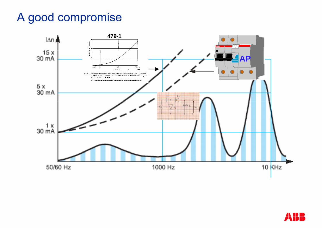
A good compromise479-1479-1
APAP

Indirect Contact Protection
The protection against indirect contact by the automatic disconnection of supplyof supply
needsneedsan appropriate Earthing Systems connected to all exposed conductive parts

Earthing Systems: TN SYSTEM
Power system:
Electrical installations:One point directly earthed (normally N point)
Exposed conductive parts connected to that point by protective conductors (PE or PEN)
TN-S system: neutral and protective functions realised by separate conductors (N and PE)TN-C system: neutral and protective functions combined in a singleconductor (PEN)conductor (PEN)TN-C-S system: neutral and protective functions combined in a singleconductor in a part of the systemco ducto a pa t o t e syste

Earthing Systems : TN SYSTEM
TN S TN C and TN C S systemsTN-S, TN-C and TN-C-S systems Typical applications:
industrial utilities or building installations fed fromindustrial, utilities or building installations fed from the M.V. network;
Medium/high TN-S values of short-circuit currents to Medium/high TN S values of short circuit currents to earth
Protection against earth-faults: Protection against earth faults: overcurrent protective devicesresidual current protective device or ground-faultresidual current protective device or ground fault releases (G function) only in TN-S system
TN-C systems: PEN-conductor can’t be interrupted

Disconnecting time in TN systems

Earthing Systems: TT SYSTEM
Power system:
Electrical installations:
One point directly earthed (normally N point)
Electrical installations:Exposed conductive parts connected to earthelectrodes electrically independent of theelectrodes electrically independent of the earth electrodes of the power system.

Earthing Systems: TT SYSTEM
T i l li ti Typical applications: domestic and small industrial installations fed by
the utilities directly from the low voltage networkthe utilities directly from the low-voltage network
Small values of short circuit currents to earth:Small values of short-circuit currents to earth: typically 10 to 100 A
Protection against earth-faults: residual current protective deviceresidual current protective deviceovercurrent protective devices

Earthing Systems: Neutral conductor
The neutral conductor is connected to the neutral point of the system and it contributes to power transmission
It makes available a voltage U0 different from the phase to phase voltage Up p g
It makes the single-phase loads functionally independent from each other p
It makes the star voltage system symmetrical enough even in the presence of non-symmetrical loads
Under specific conditions, the functions of neutral conductor and protective conductor can be combined in a single conductor PEN (TN-C system)

Earthing Systems: Neutral conductor
It makes available a voltage U0 different from the phase to phase voltage U

Earthing Systems: Neutral conductor
It makes the single phase loads functionally independent from each other
In absence of the neutral conductor, the disconnected load induces the other two loads to work at a voltage equal to Un/2the other two loads to work at a voltage equal to Un/2

Earthing Systems: Neutral conductor
It makes the star voltage system symmetrical enough even in the presence of non-symmetrical loadseven in the presence of non symmetrical loads
In absence of the neutral conductor, the sum of the currents on the loads must be zero and this causes a dissymmetry of voltages
The presence of the neutral conductor and its reduced impedance bi dbinds
the value of the star point on the load to the ideal one

Earthing Systems: Neutral conductor
Protection of the neutral conductor:
TT or TN systems:If S S b ki d i d d t t t th t l If SN S no breaking devices are needed to protect the neutral
If SN < S neutral protected but not disconnected:If SN S neutral protected but not disconnected: Detection of neutral currents is needed Opening of the phase contacts is needed
O i f th t l t t i t d d Opening of the neutral contact is not needed If INMax < INz detection of neutral currents is not needed too
In TN-C systems the neutral conductor cannot be disconnected

Earthing Systems: Neutral conductor
Protection of the neutral conductor:
IT systems:It i t l d d th t th t l h ld t b It is strongly recommended that the neutral should not be distributed
If it is distributed:If it is distributed: Detection of neutral currents is needed Opening of all the contacts (phase and neutral) is needed
Detection of neutral currents is not necessary : If the neutral is protected against SC by an upstreamIf the neutral is protected against SC by an upstream
protective device Or
If th i it i t t d b RCD ith I 0 15 I If the circuit is protected by a RCD with In 0.15INz

Indirect Contacts in TN-C-S system
Fault current in TN (C-S)
It’s a short circuit
I = U / ZIk = U0 / Zs
where:
•Zs is the impedance of the fault loop comprising the source, the live conductor up to the point of the fault and , p pthe protective conductor between the point of the fault and the source [Ω];
•U0 is the rated voltage between phase and ground

Thank YouThank You
© ABB Group July 12, 2011 | Slide 88