OpenStack 2016 - Boom or Bust? - Adrian Ionel, CEO, Mirantis - OpenStackSV 2014
Dan M. Ionel, Ph.D., FIEEE | University of Illinois, Dec. 8, 2014 | 1
On the State of the Art Design of
Electric Machines and Drives
Dan M. Ionel, Ph.D., IEEE FellowChief Engineer – Regal Beloit Corp.
Research Professor – UWM and Marquette University
December 8, 2014
University of Illinois, Urbana Champaign, IL

Dan M. Ionel, Ph.D., FIEEE | University of Illinois, Dec. 8, 2014 | 2
Outline
• Introduction• The power of collaboration
• General design procedure and main challenges
•Design of electromechanical devices and systems• Wind turbines, HEV, EV cars … and all other EMD
• Multiple dimensions and objectives; “comparing apples and oranges”
•Multi-physics analysis• Coupled electromagnetic – mechanical – thermal – flow
• Ultra-fast or Computational Efficient FEA (CE-FEA)
•Optimization• Fundamental concepts: robust design and CI - DE
• Case studies
•Conclusion.

Dan M. Ionel, Ph.D., FIEEE | University of Illinois, Dec. 8, 2014 | 3
Outline
• Introduction• The power of collaboration
• General design procedure and main challenges
•Design of electromechanical devices and systems• Wind turbines, HEV, EV cars … and all other EMD
• Multiple dimensions and objectives; “comparing apples and oranges”
•Multi-physics analysis• Coupled electromagnetic – mechanical – thermal – flow
• Ultra-fast or Computational Efficient FEA (CE-FEA)
•Optimization• Fundamental concepts: robust design and CI - DE
• Case studies
•Conclusion.

Dan M. Ionel, Ph.D., FIEEE | University of Illinois, Dec. 8, 2014 | 4
Electrical Engineering Story
Source: http://www.wikipedia.org
So
urc
e:
ww
w –
Tesl
a r
oa
dst
er

Dan M. Ionel, Ph.D., FIEEE | University of Illinois, Dec. 8, 2014 | 5
Generic Design Procedure and Main Challenges
1) Establish specification
2) Select a topology
3) Initial sizing – “back of the envelope calculations”
4) (Optimal) design electromagnetic, thermal, mechanical• Incl. estimation of performance and cost
5) Study sensitivity to manufacturing, e.g.• Tolerances on materials and processes
• Noise and vibration
6) Compare topologies
7) Make decision
Not explicitly detailed, e.g.:• System to subsystem to component decoupling
• Dynamics – time variations (4D)
• Multiple performance indices (5D, etc)…

Dan M. Ionel, Ph.D., FIEEE | University of Illinois, Dec. 8, 2014 | 6
Outline
• Introduction• The power of collaboration
• General design procedure and main challenges
•Design of electromechanical devices and systems• Wind turbines, HEV, EV cars … and all other EMD
• Multiple dimensions and objectives; “comparing apples and oranges”
•Multi-physics analysis• Coupled electromagnetic – mechanical – thermal – flow
• Ultra-fast or Computational Efficient FEA (CE-FEA)
•Optimization• Fundamental concepts: robust design and CI - DE
• Case studies
•Conclusion.

Dan M. Ionel, Ph.D., FIEEE | University of Illinois, Dec. 8, 2014 | 7
Vestas V-164 – World’s Most Powerful Wind Turbine
• Nacelle – 8x8x20 m 390 tones
• “medium – speed” drive train
• generator 710V AC and (AC/DC) rectifier
• Tower – DC power feeds down
• Base – 14 m high “E-module”
• internal power supply cabinets – 3rd floor
• the inverter DC/AC (line side) – 2nd floor
• Transformer & switchgear - 1st floor
• Multi MW wind turbines – more than 10,000 components and
many subsystems
• Just the power losses can be comparable with the output of a
smaller wind turbine!
Sources: MHI Vestas Offshore Wind
http://www.mhivestasoffshore.com/Products-and-
services/The-Turbines/V164 and
Wind Power Monthly Magazine
http://www.windpowermonthly.com/article/121105
6/close---vestas-v164-80-nacelle-hub
Dan M. Ionel, Ph.D., FIEEE | University of Illinois, Dec. 8, 2014 | 8
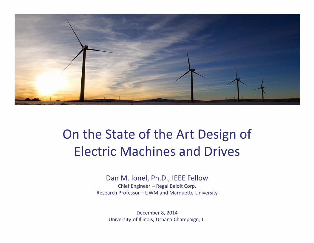
Skyscrapers and Vestas V-164
20x8x8 m
390 ton
nacelle
80 m 35 ton
blade
208 m top

Dan M. Ionel, Ph.D., FIEEE | University of Illinois, Dec. 8, 2014 | 9
From Wind to Electricity – Multi-System Multi-Physics Simulation
Sources: Valerio Viti et al., “Wind Energy Projects-
From Blade Design to Wind Farms”, ANSYS
Presentation, 2011.
Dan M. Ionel et al., “ANSYS Short Courses for
Industry”, 2011 to 2014, IEEE IEMDC 2013 and ECCE
2013 Conferences.
• Wind speed and electric power
variations
• Multiple systems and controls
• High level system simulation
• Low level – high fidelity
component simulation
• Design
• Fault analysis.

Dan M. Ionel, Ph.D., FIEEE | University of Illinois, Dec. 8, 2014 | 10
Power Electronics Reliability

Dan M. Ionel, Ph.D., FIEEE | University of Illinois, Dec. 8, 2014 | 11
Hybrid and Electric Vehicles
• Driving cycles
• US, EU etc
• Urban and highway
• Optimal design is different
depending of cycle
• Design changes also if “driving
experience” is a main
objective.
Source: Fatemi, Demerdash, Ionel, Nehl,
IEEE ITEC 2015.
0 50 100 150 200 250 3000
50
100
150
Speed(rad/s)
Torque(N.m)
0 100 200 3000
50
100
150
Speed(rad/s)
Torque(N.m)
70
70
80
80
85
85
87
87
89
89
90
90
91
91
92
92
92
93
93
93
94
94
94
95
95
96
96
97
Speed (RPM)
Torq
ue (
N.m
)
500 1000 1500 2000 2500 3000 3500 4000 4500 5000 5500 6000
50
100
150
200
250
300
80
82
84
86
88
90
92
94
96
70
70
80
80
85
85
87
87
89
89
90
90
91
91
91
92
92
92
9393
9394
94
94
95
95
96
96
Speed (RPM)
Torq
ue (
N.m
)
500 1000 1500 2000 2500 3000 3500 4000 4500 5000 5500 6000
50
100
150
200
250
300
80
82
84
86
88
90
92
94
96
Dan M. Ionel, Ph.D., FIEEE | University of Illinois, Dec. 8, 2014 | 12
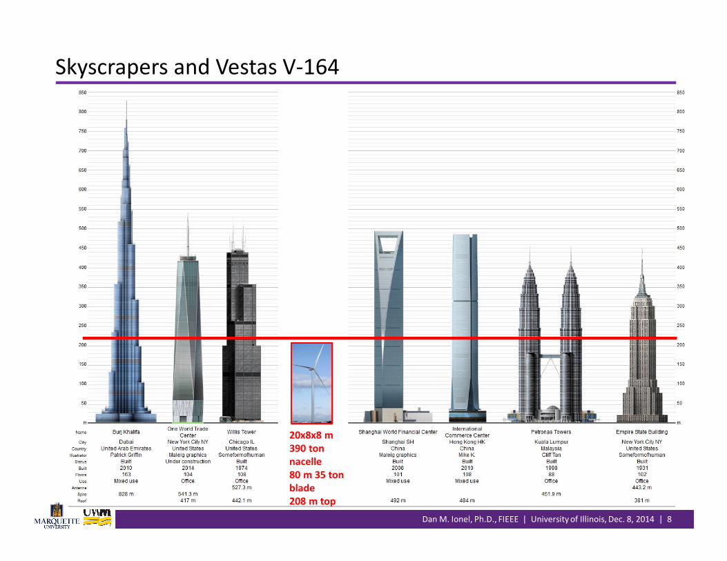
See: "Electric Motor Drive Selection Issues for HEV Propulsion Systems: A
Comparative Study,“ IEEE Transactions on Vehicular Technology, 2006.
Example Motor Drive Comparison for HEV Traction

Dan M. Ionel, Ph.D., FIEEE | University of Illinois, Dec. 8, 2014 | 13
Systematic Optimal Design Comparison
• Ensuring a fair basis for comparison
• Thousands of candidate designs have to be analyzed
• Pareto front – collection of “best” (optimal/compromise) designs, e.g.
– cost vs. efficiency tradeoffs
• Study should include sensitivity to manufacturing tolerances. 13

Dan M. Ionel, Ph.D., FIEEE | University of Illinois, Dec. 8, 2014 | 14
A Generic Procedure for Systematic Design
1) Establish specification
2) Select a topology
3) Initial sizing – “back of the envelope calculations”
4) (Optimal) design electromagnetic, thermal, mechanical
- Incl. estimation of performance and cost
5) Study sensitivity to manufacturing, e.g.
- Tolerances on materials and processes
- Noise and vibration
6) Compare topologies
7) Make decision.

Dan M. Ionel, Ph.D., FIEEE | University of Illinois, Dec. 8, 2014 | 15
“Back of the Envelope Calculations” – Example “Stories”
• Initial sizing and/or scaling, including topology selection
• Performed by experts and novices � recommendations for the design process
• Many times, parts of the recommendations get lost in the communications
• “The 12 slot 10 pole configuration is very good (“the best”) for brushless PM
synchronous motors” – typical omissions in the communications
• Provided that the core losses are not significant because speed in relatively low, and high-
performance low-loss silicon steel is employed
• Provided that eccentricity can be maintained low due tight tolerance control
• Provided that the effect of high radial forces can be decoupled/dampened in the system
• “The synchronous reluctance motor can have higher specific torque and efficiency
than its induction motor counter part” – typical omissions in the communications
• Provided that the saliency ratio of the synchronous reluctance motor is very high with
values of 7-10
• Provided that the additional (stray-load) core losses are kept low through material selection
and process control
• In industrial practice many of the “provided that” conditions may actually be quite
difficult to achieve, to say the least…

Dan M. Ionel, Ph.D., FIEEE | University of Illinois, Dec. 8, 2014 | 16
Some of the Design Challenges
• Wind turbine objective
• Minimum Cost of Energy (COE)
• Reliability
• HEV (or EV) objectives
• Minimum Cost of Operation
• “Best Driving Experience”
• Typical electric machines and drives objectives
• Cost: materials, manufacturing, operating, total
• Performance: losses (efficiency), ripple, vibration-noise etc.
• Establish the trade offs cost vs. performance and “position” according to a strategy
• Many “truly” independent design variables, typically 10-20
• Multi-dimensional design problem: 2D, 3D, 4D, 5D…
• Problems are “weakly” coupled
• System – component
• Electromagnetic – mechanical – thermal
• Analysis is too slow, e.g. electromagnetic FEA is needed
• Optimization requires too many candidate designs
• … and the list can go on and on …

Dan M. Ionel, Ph.D., FIEEE | University of Illinois, Dec. 8, 2014 | 17
Outline
• Introduction• The power of collaboration
• General design procedure and main challenges
•Design of electromechanical devices and systems• Wind turbines, HEV, EV cars … and all other EMD
• Multiple dimensions and objectives; “comparing apples and oranges”
•Multi-physics analysis• Coupled electromagnetic – mechanical – thermal – flow
• Ultra-fast or Computational Efficient FEA (CE-FEA)
•Optimization• Fundamental concepts: robust design and CI - DE
• Case studies
•Conclusion.

Dan M. Ionel, Ph.D., FIEEE | University of Illinois, Dec. 8, 2014 | 18
Brushless PM Motors and Power Electronics Drives
� Controls and PE
circuits
� Multi-physics
� Current regulation.

Dan M. Ionel, Ph.D., FIEEE | University of Illinois, Dec. 8, 2014 | 19
Coupled Field and Circuit Simulations

Dan M. Ionel, Ph.D., FIEEE | University of Illinois, Dec. 8, 2014 | 20
• Electromagnetic field and electric circuit equations
• Electromagnetic torque and motion equations.
Behind the Electromagnetic Field Animations
Dan M. Ionel, Ph.D., FIEEE | University of Illinois, Dec. 8, 2014 | 21
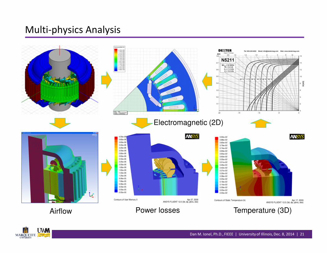
Multi-physics Analysis
Electromagnetic (2D)
Airflow Power losses Temperature (3D)

Dan M. Ionel, Ph.D., FIEEE | University of Illinois, Dec. 8, 2014 | 22
Ultra-fast or Computationally Efficient FEA (CE-FEA)
• The fundamentals of electromagnetic CE-FEA– sine-wave current regulated synchronous machines, brushless PM included
– steady-state operation
– 2D or 3D versions
– any geometry
– calculates all major performance indices and parameters
– induced voltage waveform, torque and torque ripple, core losses, PM losses, and
inductances
– fully exploits symmetries of electric and magnetic circuits to reduce simulation
time
– min. number of magnetostatic solutions, correlated with the max. order of
significant field harmonics
– multiple IEEE Transactions papers since 2010, including an award winner
• Main benefits– one-to-two orders of magnitude reduction of simulation time; days vs. months!
– thousands of designs in hours on state of the art workstation
– 10-20 seconds per design (e.g. 6 static 2D - FE solutions)
– enables large scale optimization studies.

Dan M. Ionel, Ph.D., FIEEE | University of Illinois, Dec. 8, 2014 | 23
( ) ( )θθ ++ −=+Y
o
RAA 60
( ) ( )θθ ++ =+B
o
RAA 120
-0.0100
-0.0080
-0.0060
-0.0040
-0.0020
0.0000
0.0020
0.0040
0.0060
0.0080
0.0100
0 20 40 60 80 100 120 140 160 180
[Wb
/m
]
[deg. el.]
R+
Y+
B+
-0.01
-0.008
-0.006
-0.004
-0.002
1.2E-17
0.002
0.004
0.006
0.008
0.01
0 20 40 60 80 100 120 140 160 180
[Wb
/m
]
[deg. el.]
R+
Y+
B+
-0.0100
-0.0080
-0.0060
-0.0040
-0.0020
0.0000
0.0020
0.0040
0.0060
0.0080
0.0100
0 20 40 60 80 100 120 140 160 180
[Wb
/m
]
[deg. el.]
R+
Y+
B+
• Coil side MVP, AR+
• Results also include: cogging and ripple torque, induced
voltage, (inductances), core and PM losses.
Five magnetostatic FE solutions
AY+
AB+
AR+
ΦR
One magnetostatic FE solution
Principles of CE-FEA (1/2)

Dan M. Ionel, Ph.D., FIEEE | University of Illinois, Dec. 8, 2014 | 24
Principles of CE-FEA (2/2)
• Harmonic calculations – flux linkage, back emf, and electromagnetic torque
• Flux density calculations based on symmetry
• Core loss calculation due to fundamental and low frequency harmonics
( ) ( )∑=
+=M
R
ν
ννν φνθλθλ
1
cos
( ) ( )∑=
+=−=M
dt
d
d
de
R
R
ν
ννν φνθνλω
θ
θ
λθ
1
sin

Dan M. Ionel, Ph.D., FIEEE | University of Illinois, Dec. 8, 2014 | 25
CE-FEA Hybrid Numerical and Analytical – Losses in PM
25/21
B11 B12 B13 B14

Dan M. Ionel, Ph.D., FIEEE | University of Illinois, Dec. 8, 2014 | 26
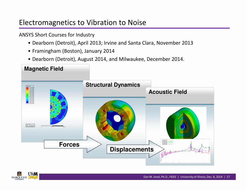
Coupling of Forces, Vibration and Noise
• Electromagnetic forces• Maxwell stress – electromagnetic
pressure in 3D
• Forces produce mechanical displacement
• Sound power calculated from displacement
• Noise is calculated from sound power
• “Strong” vs. “weak” coupling.
26
Dan M. Ionel, Ph.D., FIEEE | University of Illinois, Dec. 8, 2014 | 27
Magnetic Field
Structural Dynamics
Acoustic Field
ForcesDisplacements
ANSYS Short Courses for Industry
• Dearborn (Detroit), April 2013; Irvine and Santa Clara, November 2013
• Framingham (Boston), January 2014
• Dearborn (Detroit), August 2014, and Milwaukee, December 2014.
Electromagnetics to Vibration to Noise
Dan M. Ionel, Ph.D., FIEEE | University of Illinois, Dec. 8, 2014 | 28
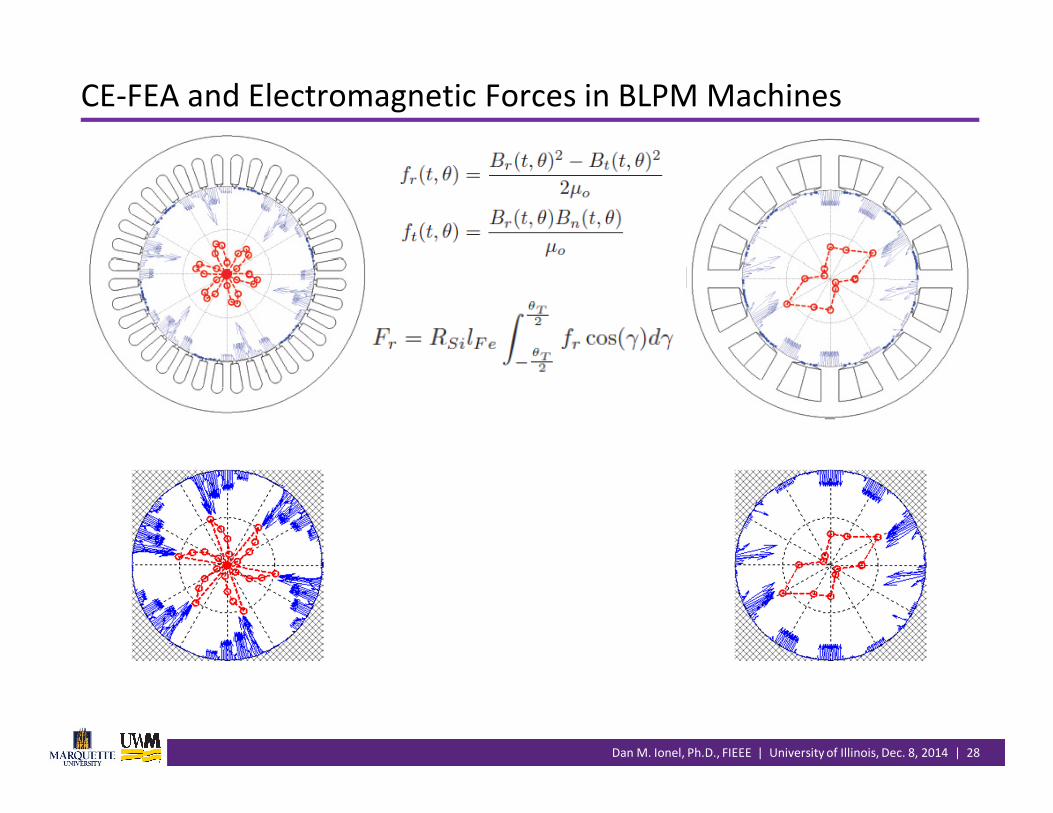
CE-FEA and Electromagnetic Forces in BLPM Machines
Dan M. Ionel, Ph.D., FIEEE | University of Illinois, Dec. 8, 2014 | 29
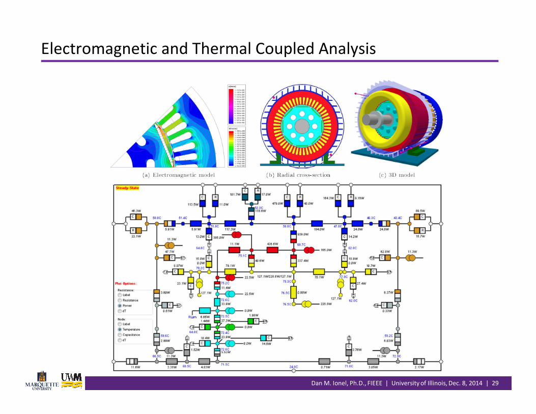
Electromagnetic and Thermal Coupled Analysis
Dan M. Ionel, Ph.D., FIEEE | University of Illinois, Dec. 8, 2014 | 30
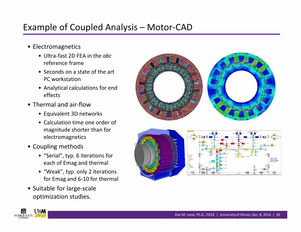
Example of Coupled Analysis – Motor-CAD
• Electromagnetics
• Ultra-fast 2D FEA in the abc
reference frame
• Seconds on a state of the art
PC workstation
• Analytical calculations for end
effects
• Thermal and air-flow
• Equivalent 3D networks
• Calculation time one order of
magnitude shorter than for
electromagnetics
• Coupling methods
• “Serial”, typ. 6 iterations for
each of Emag and thermal
• “Weak”, typ. only 2 iterations
for Emag and 6-10 for thermal
• Suitable for large-scale
optimization studies.

Dan M. Ionel, Ph.D., FIEEE | University of Illinois, Dec. 8, 2014 | 31
• EM analysis takes tens of seconds
• Thermal and air-flow problem
takes only seconds to solve
• Traditional approach typically
requires 6 or more iterations
• In synchronous motors the rotor
losses are typically low
• Variation of core losses with
temperature at given current is
relatively small.
Traditional approach New ultrafast approach
Traditional and Ultrafast Coupling Method

Dan M. Ionel, Ph.D., FIEEE | University of Illinois, Dec. 8, 2014 | 32
• Charging Simulation with High Performance Computing (HPC) – White Paper and IEEE Webinar by
Bradley Smith of GM Corp., and Scott Stanton of ANSYS Inc.
• “A 16x speed up on a computer farm delivers time and cost savings in the design of traction
motors for HEVs and EVS. “
HPC Implementation – GM and ANSYS Example
Dan M. Ionel, Ph.D., FIEEE | University of Illinois, Dec. 8, 2014 | 33
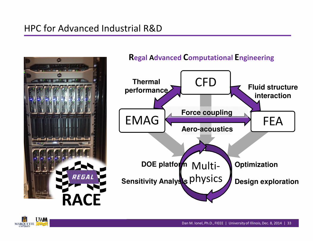
Multi-physics
EMAG
CFD
FEA
Fluid structure
interaction
Thermal
performance
Force coupling
Aero-acoustics
Optimization
Design exploration
DOE platform
Sensitivity Analysis
Regal Advanced Computational Engineering
HPC for Advanced Industrial R&D
Dan M. Ionel, Ph.D., FIEEE | University of Illinois, Dec. 8, 2014 | 34
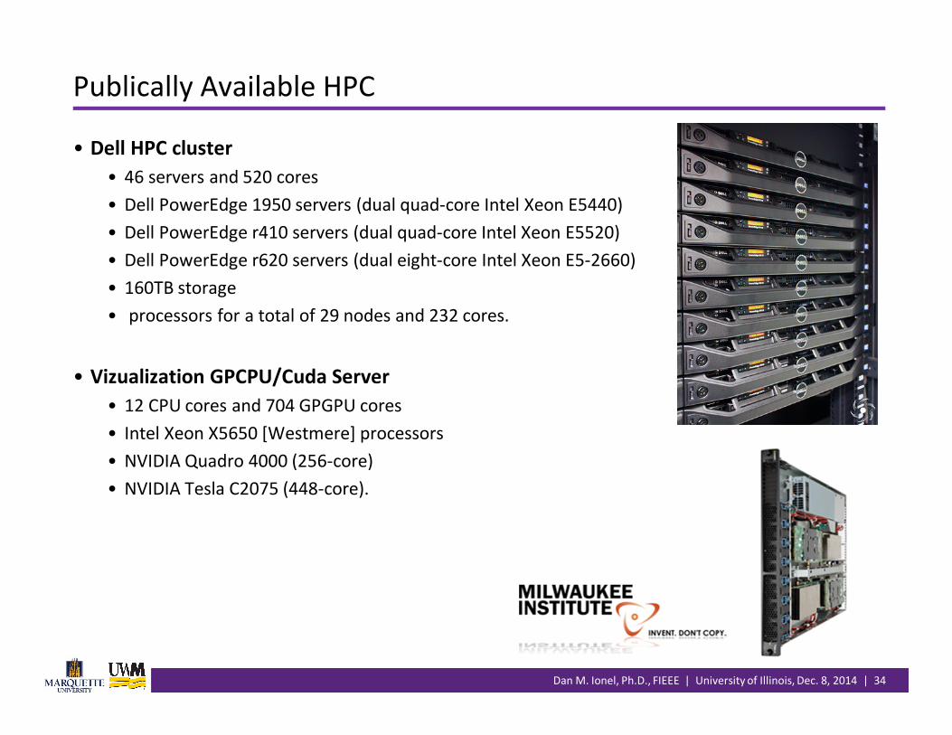
Publically Available HPC
• Dell HPC cluster
• 46 servers and 520 cores
• Dell PowerEdge 1950 servers (dual quad-core Intel Xeon E5440)
• Dell PowerEdge r410 servers (dual quad-core Intel Xeon E5520)
• Dell PowerEdge r620 servers (dual eight-core Intel Xeon E5-2660)
• 160TB storage
• processors for a total of 29 nodes and 232 cores.
• Vizualization GPCPU/Cuda Server
• 12 CPU cores and 704 GPGPU cores
• Intel Xeon X5650 [Westmere] processors
• NVIDIA Quadro 4000 (256-core)
• NVIDIA Tesla C2075 (448-core).
Dan M. Ionel, Ph.D., FIEEE | University of Illinois, Dec. 8, 2014 | 35
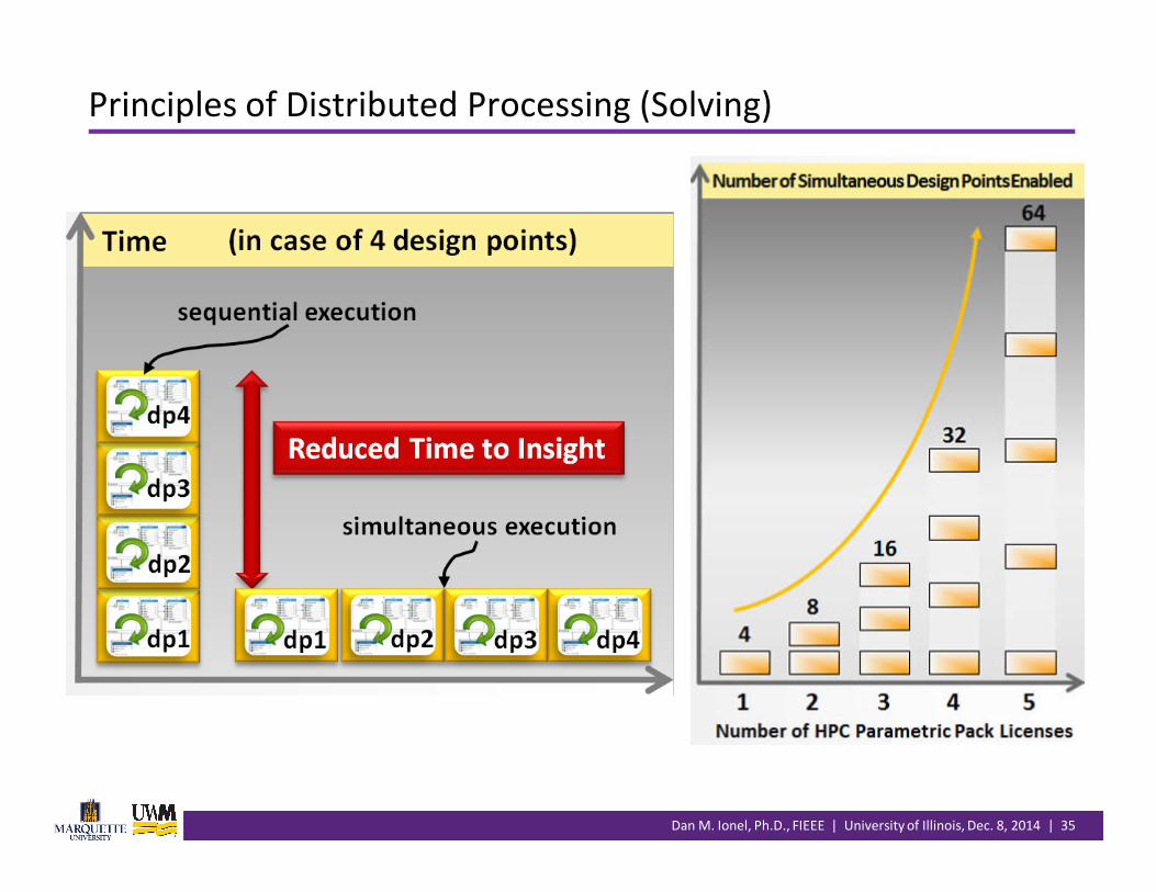
Principles of Distributed Processing (Solving)

Dan M. Ionel, Ph.D., FIEEE | University of Illinois, Dec. 8, 2014 | 36
HPC – Mechanical, CFD, and Electromagnetics Examples

Dan M. Ionel, Ph.D., FIEEE | University of Illinois, Dec. 8, 2014 | 37
• 3D IPM synchronous machine with motion
• Mesh size: 120,000 tets – around 2 GB of RAM
• Machine: 4 x Xeon CPU [email protected] processors
• (32 cores total – 512 GB of RAM)
• Basic math for electromagnetic analysis only…
– 6,000 candidate designs – 1 minute/design – 100 core hours
– more than 4 days or…
HPC Solution – Example Model
Number of Cores Average Time per
Non linear Iteration (s)
Average Speed-up
Compared w/1 core
1 70 -
2 41 1.7
4 21 3.3
8 18 3.9
12 18 3.9
Dan M. Ionel, Ph.D., FIEEE | University of Illinois, Dec. 8, 2014 | 38
Outline
• Introduction• The power of collaboration
• General design procedure and main challenges
•Design of electromechanical devices and systems• Wind turbines, HEV, EV cars … and all other EMD
• Multiple dimensions and objectives; “comparing apples and oranges”
•Multi-physics analysis• Coupled electromagnetic – mechanical – thermal – flow
• Ultra-fast or Computational Efficient FEA (CE-FEA)
•Optimization• Fundamental concepts: robust design and CI - DE
• Case studies
•Conclusion.

Dan M. Ionel, Ph.D., FIEEE | University of Illinois, Dec. 8, 2014 | 39
• Design of Experiments (DOE)
• Parameter correlation
• Response surface (RS)
• Estimated performance based on RS
• (Six) Sigma analysis
• Advantages
• Familiar engineering background
• Includes indications of input-output correlations and sensitivities.
Electric machine specification and initial design
Cost vs. performance characteristics � best designs
• Computational Intelligence
– Differential Evolution (DE);
others: GA, PSO etc
– Inspired from natural selection
– Generations /populations, each
with multiple individuals
• Advantages
– Minimal computational effort
for large scale optimization
studies (thousands of candidate
designs).
Methods for Automated Design Optimization

Dan M. Ionel, Ph.D., FIEEE | University of Illinois, Dec. 8, 2014 | 40
Which Method Is Better – RS or DE?
• Duan and Ionel (2011) paper - review
and benchmark problem
• Five independent variables, strong
non-linear output
• Two design objectives minimize
“weight” while maximizing “goodness”
• Design candidates evaluated on a
direct “reference” grid: 16,807
• RS vs. DE
�/2
��
���
��
150 200 25011
11.2
11.4
11.6
11.8
12
Weight function (kg)G
oo
dn
ess
fu
ncti
on
(N
m/W
0.5
)
Direct Search
DE2200
DE1024
DE240
DE45
RS1024
RS243
RS46
No. of candidates Comparison Result
Small Comparable
Medium DE better
Large DE better

Dan M. Ionel, Ph.D., FIEEE | University of Illinois, Dec. 8, 2014 | 41
� Differential Evolution:
� Initialization
�,�,� = �����(0,1) ∙ ( �_��� − �_�� ) + �_��
� Mutation
� Crossover
� Selection
� Stopping criterion: " = #�
� Definition of Variables:
� $ = 1, 2,⋯ ,�& ,
number of design variables, �& = 6.
� ( = 1, 2,⋯ ,)*,
number of individuals per generation
� ": index of current generation
� Typically for electric machine problems
� 10-20 independent variables
� 100-150 individuals (candidate designs) per
generation
� 60-80 generations per optimization study.
Differential Evolution Algorithm

Dan M. Ionel, Ph.D., FIEEE | University of Illinois, Dec. 8, 2014 | 42
Industrial Examples – RBC NEMA Range of IPM Motors
0.8 1 1.2 1.4 1.6 1.8
0.8
1
1.2
1.4
1.6
1.8
2
Losses, PCu
+ PFe
+ Ppm
+ Pme
[pu]
Co
st [p
u]
Co
st p
er
ou
tpu
t p
ow
er
[pu
]
0.8
0.85
0.9
0.95
1
1.05
1.1
1.15
M-1
M-2
M-3
Dan M. Ionel, Ph.D., FIEEE | University of Illinois, Dec. 8, 2014 | 43
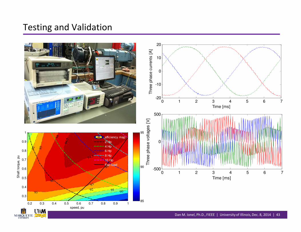
Testing and Validation
89
9091
91
92
92
93
93
93
94
94
94
94.5
94.5
speed, pu
Shaft
torq
ue,
pu
0.2 0.3 0.4 0.5 0.6 0.7 0.8 0.9 1
0.3
0.4
0.5
0.6
0.7
0.8
0.9
1
85
90
95
efficiency map
2 Hp
4 Hp
6 Hp
8 Hp
10 Hp
Fan load
0 1 2 3 4 5 6 7-20
-10
0
10
20
Time [ms]
Th
ree p
has
e c
urr
ents
[A
]
0 1 2 3 4 5 6 7-500
0
500
Time [ms]
Thre
e p
hase v
oltages [
V]
Dan M. Ionel, Ph.D., FIEEE | University of Illinois, Dec. 8, 2014 | 44
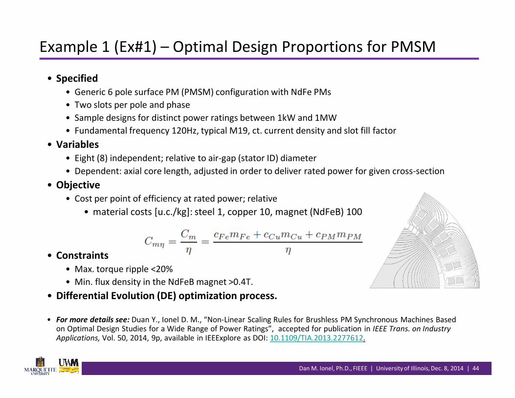
Example 1 (Ex#1) – Optimal Design Proportions for PMSM
• Specified
• Generic 6 pole surface PM (PMSM) configuration with NdFe PMs
• Two slots per pole and phase
• Sample designs for distinct power ratings between 1kW and 1MW
• Fundamental frequency 120Hz, typical M19, ct. current density and slot fill factor
• Variables
• Eight (8) independent; relative to air-gap (stator ID) diameter
• Dependent: axial core length, adjusted in order to deliver rated power for given cross-section
• Objective
• Cost per point of efficiency at rated power; relative
• material costs [u.c./kg]: steel 1, copper 10, magnet (NdFeB) 100
• Constraints
• Max. torque ripple <20%
• Min. flux density in the NdFeB magnet >0.4T.
• Differential Evolution (DE) optimization process.
• For more details see: Duan Y., Ionel D. M., “Non-Linear Scaling Rules for Brushless PM Synchronous Machines Based on Optimal Design Studies for a Wide Range of Power Ratings”, accepted for publication in IEEE Trans. on Industry
Applications, Vol. 50, 2014, 9p, available in IEEExplore as DOI: 10.1109/TIA.2013.2277612.

Dan M. Ionel, Ph.D., FIEEE | University of Illinois, Dec. 8, 2014 | 45
Ex#1 – Parametric Model and Independent Variables
• Eight independent variables, relative to air-gap diameter and minimum gap
• Minimum physical air-gap [mm]:
• Slot pitch
• Pole pitch
Dan M. Ionel, Ph.D., FIEEE | University of Illinois, Dec. 8, 2014 | 46
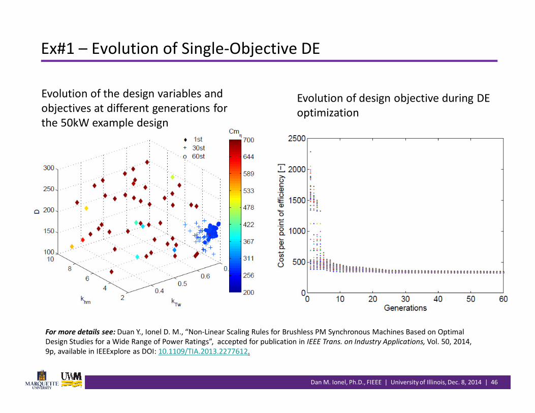
Ex#1 – Evolution of Single-Objective DE
Evolution of the design variables and
objectives at different generations for
the 50kW example design
Evolution of design objective during DE
optimization
For more details see: Duan Y., Ionel D. M., “Non-Linear Scaling Rules for Brushless PM Synchronous Machines Based on Optimal
Design Studies for a Wide Range of Power Ratings”, accepted for publication in IEEE Trans. on Industry Applications, Vol. 50, 2014,
9p, available in IEEExplore as DOI: 10.1109/TIA.2013.2277612.

Dan M. Ionel, Ph.D., FIEEE | University of Illinois, Dec. 8, 2014 | 47
Ex#1 – Optimization Results (1/3)

Dan M. Ionel, Ph.D., FIEEE | University of Illinois, Dec. 8, 2014 | 48
Ex#1 – Optimization Results (3/3)
• Design proportions across a wide range of power ratings – confirmed many of the typical experienced based “rules of thumb” and reveled other insights
• More than 30,000 designs have been studied!
• Influenced of course by the optimization criteria considered and the relative cost of materials (Fe 1, Cu 10, NdFeB 100)
• Average value of magnet length (thickness) to air-gap ratio approx. 3 and increasing with power rating
• Pole arc approx. 0.65 to 0.7
• Tooth width to slot width 1:1 (equal split)
• Magnetic loading: stator tooth 1.65T, back iron 1.5T
• Split ratio air-gap diameter to outer stator approx. 0.55 to 0.6
• Rotor length to air-gap diameter approx. 1.1 to 1.4
• Percentage of copper loss to total loss variation 35% to 60%, decreasing with power rating
• Cost and performance
• Optimal designs very close to the 20% torque ripple imposed limit (indication of convergence from an engineering point of view)
• Efficiency in the range of 93.9% to 98.8%, increasing with power rating (not taking into account PM losses, and mechanical losses)
• Large machines dominated by NdFeB cost (approx. 50%); lower values for smaller machines
• Changes in the cost of materials will result in principle in different optimal designs.
Dan M. Ionel, Ph.D., FIEEE | University of Illinois, Dec. 8, 2014 | 49
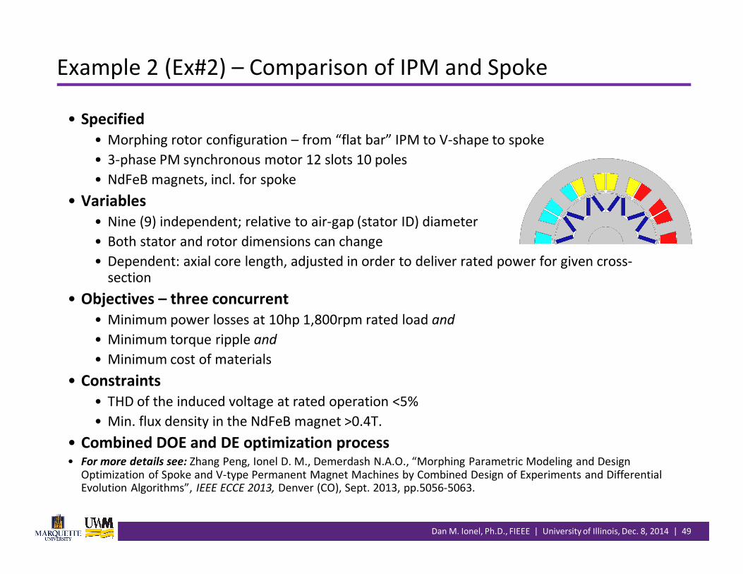
Example 2 (Ex#2) – Comparison of IPM and Spoke
• Specified
• Morphing rotor configuration – from “flat bar” IPM to V-shape to spoke
• 3-phase PM synchronous motor 12 slots 10 poles
• NdFeB magnets, incl. for spoke
• Variables
• Nine (9) independent; relative to air-gap (stator ID) diameter
• Both stator and rotor dimensions can change
• Dependent: axial core length, adjusted in order to deliver rated power for given cross-section
• Objectives – three concurrent
• Minimum power losses at 10hp 1,800rpm rated load and
• Minimum torque ripple and
• Minimum cost of materials
• Constraints
• THD of the induced voltage at rated operation <5%
• Min. flux density in the NdFeB magnet >0.4T.
• Combined DOE and DE optimization process• For more details see: Zhang Peng, Ionel D. M., Demerdash N.A.O., “Morphing Parametric Modeling and Design
Optimization of Spoke and V-type Permanent Magnet Machines by Combined Design of Experiments and Differential Evolution Algorithms”, IEEE ECCE 2013, Denver (CO), Sept. 2013, pp.5056-5063.

Dan M. Ionel, Ph.D., FIEEE | University of Illinois, Dec. 8, 2014 | 50
Ex#2 – Morphing Rotor Topology from IPM to Spoke
• For more details see: Zhang Peng, Ionel D. M., Demerdash N.A.O., “Morphing Parametric Modeling and Design Optimization of
Spoke and V-type Permanent Magnet Machines by Combined Design of Experiments and Differential Evolution Algorithms”,
IEEE ECCE 2013, Denver (CO), Sept. 2013, pp.5056-5063.
12S10P Spoke12S10P V-SV IPM
12S10P “Flat Bar”
IPM
12S10P V-FV IPM

Dan M. Ionel, Ph.D., FIEEE | University of Illinois, Dec. 8, 2014 | 51
Ex#2 – RS and DE for Spoke Ferrite Designs
Dan M. Ionel, Ph.D., FIEEE | University of Illinois, Dec. 8, 2014 | 52
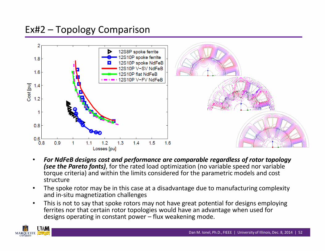
Ex#2 – Topology Comparison
• For NdFeB designs cost and performance are comparable regardless of rotor topology (see the Pareto fonts), for the rated load optimization (no variable speed nor variable torque criteria) and within the limits considered for the parametric models and cost structure
• The spoke rotor may be in this case at a disadvantage due to manufacturing complexity and in-situ magnetization challenges
• This is not to say that spoke rotors may not have great potential for designs employing ferrites nor that certain rotor topologies would have an advantage when used for designs operating in constant power – flux weakening mode.
Dan M. Ionel, Ph.D., FIEEE | University of Illinois, Dec. 8, 2014 | 53
Outline
• Introduction• The power of collaboration
• General design procedure and main challenges
•Design of electromechanical devices and systems• Wind turbines, HEV, EV cars … and all other EMD
• Multiple dimensions and objectives; “comparing apples and oranges”
•Multi-physics analysis• Coupled electromagnetic – mechanical – thermal – flow
• Ultra-fast or Computational Efficient FEA (CE-FEA)
•Optimization• Fundamental concepts: robust design and CI - DE
• Case studies
•Conclusion.

Dan M. Ionel, Ph.D., FIEEE | University of Illinois, Dec. 8, 2014 | 54
•Multiple steps are involved in a systematic design process
•Special care should be taken with the initial topology selection and
design sizing, including “back of the envelope calculations”
•Multi-physics analysis electromagnetic-thermal-mechanical for
satisfactorily accurate or high-fidelity models
•The effect of manufacturing on performance and cost should be
quantified
•Automated design optimization can serve to study hundreds or
thousands of candidate designs and provide the “best” design, or
family of designs
•A “fair” evaluation of topologies and candidate designs should be
based on the results of optimal design studies.
Recommendations
Dan M. Ionel, Ph.D., FIEEE | University of Illinois, Dec. 8, 2014 | 55
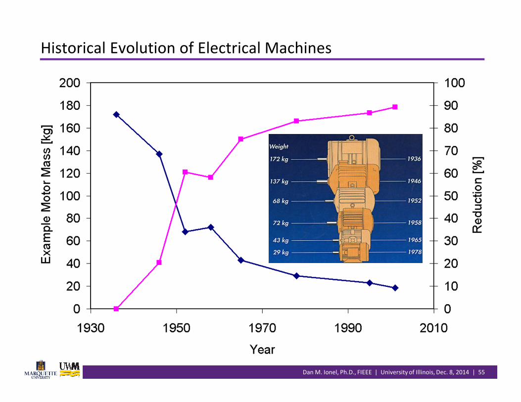
Historical Evolution of Electrical Machines

Dan M. Ionel, Ph.D., FIEEE | University of Illinois, Dec. 8, 2014 | 56
The Impact of Electronics and Magnets
VSD Induction Motor
Higher Polarity (Speed)
New Gen. Improved Steel
Higher Efficiency
Aluminum Frame
50% Motor Part Reduction
IPM Motor
Even Higher Polarity (Speed)
Even Higher Efficiency
Similar Enclosure
Quieter Operation

Dan M. Ionel, Ph.D., FIEEE | University of Illinois, Dec. 8, 2014 | 57
Continuous Improvement…
•Not to forget that we made progress with the machines and drives
•But the design methods are in need for continuous improvement
•Things that we could not do, in terms of practical design
• One hundred years ago – …
• Ten years ago – 3D, large scale multi-objective optimization with high-fidelity models
• Last year – confirm through CI the “golden” design rules
•Among the many things that need improvement• “Stronger” coupling
• System – component
• Electromagnetic – mechanical – thermal
• Multiple dimensions: 2D, 3D, 4D, 5D…
•Interdisciplinary engineering and collaboration are vital.

Dan M. Ionel, Ph.D., FIEEE | University of Illinois, Dec. 8, 2014 | 58
Acknowledgments and Recent References
• Special thanks to the many collaborators at Regal, Vestas, ANSYS and MDL, and to
colleagues and students at Marquette University and University of Wisconsin –
Milwaukee.
• Recent papers and presentations• Novakovic B., Duan Y., Solveson M., Nasiri A., Ionel D. M., “Comprehensive Modeling of Turbine Systems from Wind to Electric Grid”,
accepted for publication in IEEE Trans. on Industry Applications, Vol. 51, 2015, 11p.
• Zhang Peng, Sizov G. Y., Li M., Ionel D. M., Demerdash N. A. O., Stretz S. J., Yeadon A. W., “Multi-Objective Tradeoff in the Design
Optimization of a Brushless Permanent-Magnet Machine with Fractional-Slot Concentrated Windings”, IEEE Trans. on Industry
Applications, Vol. 50, No. 6, Nov/Dec 2014, pp. 3285-3294.
• Ionel D.M., “The World’s Most Powerful Wind Turbine – Vestas V164”, Intl. Conf. on Renewable Energy Research and Applications
ICRERA 2014, Milwaukee (WI), Oct. 2014, invited panel presentation.
• Ionel D.M., “Design for Manufacturing Employing Automated Design Optimization and Multi-Physics Analysis – an Academic and
Industrial Point of View”, Special Session “Optimization of Electric Motors and Multi-Physics Analysis”, IEEE ECCE 2014, Pittsburgh
(PA), Sept. 2014, invited presentation.
• Wang Yi, Ionel D.M., Staton D.A., “Ultrafast Steady State Multi-Physics Model for PM and Synchronous Reluctance Machines”, Rec.
IEEE ECCE 2014, Pittsburgh (PA), Sept. 2014, pp.5152-5159.
• Duan Y., Ionel D. M., “Non-Linear Scaling Rules for Brushless PM Synchronous Machines Based on Optimal Design Studies for a Wide
Range of Power Ratings, IEEE Trans. on Industry Applications, Vol. 50, No.2, Mar/Apr 2014, pp. 1044-1052.
• Zhang P., Sizov G. Y., He J., Ionel D. M., Demerdash N. A. O., “Calculation of Magnet Losses in Concentrated-Winding Permanent
Magnet Synchronous Machines Using a Computationally Efficient – Finite Element Method”, IEEE Trans. on Industry Applications, Vol.
49, No. 6, Nov/Dec 2013, pp. 2524-2532.
• Sizov, G. Y., Zhang P., Ionel D. M., Demerdash N. A. O., “Automated Multi-Objective Design Optimization of PM AC Machines Using
Computationally Efficient-FEA and Differential Evolution”, IEEE Trans. on Industry Applications, Vol. 49, No. 5, Sept/Oct 2013, pp.
2086-2096.
• Duan Y., Ionel D. M., “A Review of Recent Developments in Electrical Machine Design Optimization Methods with a Permanent
Magnet Synchronous Motor Benchmark Study”, IEEE Trans. on Industry Applications, Vol. 49, No. 3, May/June 2013, pp. 1268-1275.