A critical investigation of motivating factors responsible ...
Proceedings of the
Annual Stability Conference
Structural Stability Research Council
San Antonio, Texas, March 21-24, 2017
On the investigation of the most critical shape imperfections for wind turbine
tower shell structures
Kshitij Kumar Yadav1, Jens Lycke Wind 2, Simos Gerasimidis 3
Abstract
As the wind power industry is the fastest growing energy resource in the world, wind turbine
structures have been continuously increasing their dimensions and in particular their height, a trend
which is expected to continue in the future. The height of wind turbines has doubled during the
last 10 years and their power has increased by a factor of 5. This increase in height comes along
with an overwhelming increase in the construction cost as well as with a plethora of emerging
problems involving design/construction/erection processes. The present paper studies the problem
of the most critical geometrical imperfections for the buckling capacity of wind turbine tower shell
structures. The presented study is applied to many different tower geometries and includes linear
elastic as well as plastic buckling through a series of nonlinear finite element calculations. The
most critical geometrical shape imperfection is calculated through the parametric interaction of the
buckling modes of the shell tower structure. The results present the sensitivity of the buckling
capacity of the shell structure to the interaction of the modes considered as the geometrical onset
for the nonlinear finite element analysis. The produced interactions are compared to the widely
applied Eurocode design codes and useful conclusions are drawn.
1. Introduction
The use of wind turbines is increasing continuously and it is anticipated that this trend will
accelerate in the coming future. The need for more vigorous wind harvesting has given impetus to
many technological advances, but also to making more efficient and less expensive wind turbines.
Among the many technical goals of today’s wind energy industry is to develop solutions for taller
wind turbine towers. The increase in height of wind turbine towers is imperative to achieve these
goals as the wind profile is stronger at higher heights (Khatri 2010). However, making higher wind
turbine tower structures, poses numerous challenges to structural engineers.
Traditionally, thin hollow cylindrical shells are used for making wind turbine towers due to their
economical and constructional advantages. It is well known from the groundbreaking work by
1 PhD Candidate, University of Massachusetts, Amherst, <[email protected]> 2 Structural Engineer, Vestas Wind Systems A/S, <[email protected]> 3 Assistant Professor, University of Massachusetts, Amherst, <[email protected]>
2
Koiter (1945) that cylindrical shells are highly imperfection sensitive structures when subjected to
compressive stresses. This property of course depends on their characteristics and mainly on how
thin they are in terms of R/t (R is the radius and t the thickness of the shell). In addition, their
capacity depends strongly on the extent of residual stresses due to manufacturing or construction
and assembly process. For wind turbine towers, the increase in height renders the stability and
imperfection sensitivity of the tower as very important design issues.
Wind turbine tower structures are mainly subjected to bending moment coming from the lateral
wind load and axial force coming from the weight of the nacelle placed at the top the tower. The
study of cylindrical shells (not necessarily wind turbine structures) has occupied the research
community for years (Hutchinson 1965, Kyriakides 1982, Karamanos 1991). However, the
problem of the scale of very tall wind turbine towers is relatively new (Guo et. al. 2013, Abdulla
et. al. 2015, Jay et. al. 2016).
This paper deals with the imperfection sensitivity of a real wind turbine tower under bending
moment and studies the problem of worst shape geometric imperfection. The worst shape
imperfection is defined as the shape of imperfection that leads to the lowest critical load of the
structure (Lindgaard et. al. 2010, Deml et. al. 1997). For the present study, mode shapes of elastic
buckling are taken as the pattern of geometric imperfection and their effect on the load carrying
capacity is studied. The mechanism of buckling and the imperfection sensitivity of the tower are
discussed in detail. Finally, the effect of variation of the amplitude of the imposed imperfection is
also studied for the case which leads to the lowest critical load (the worst shape imperfection).
2. Geometry of the Tower and Finite Element Modeling
2.1 Mechanical Model
The geometry of the wind turbine tower for this study is a 3.6 MW Vestas turbine. The bottom of
the tower is assumed to be fixed and the top of tower is assumed to be free. These assumptions are
reasonable as the bottom of the tower is attached to the foundation and the top is attached to the
rotor.
2.2 Finite Element Modeling
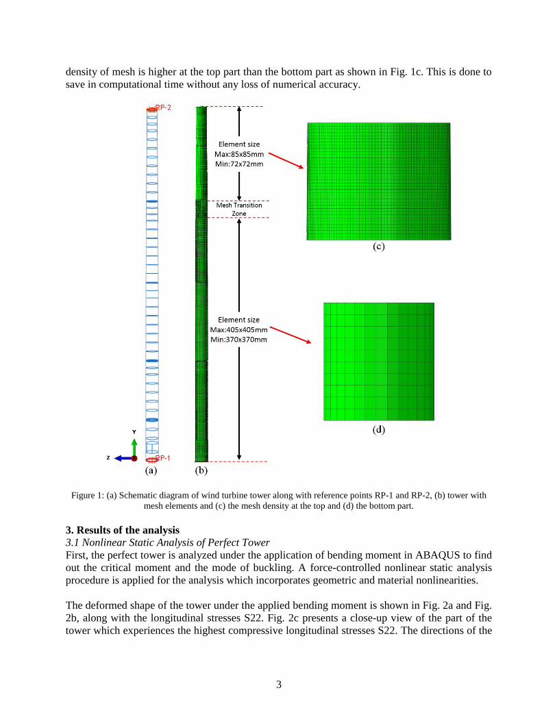
The simulation of this tower is done in the finite element package ABAQUS (2016). A total of
70195 S4R shell elements are used for the modeling. For simulating the boundary conditions and
applied bending moment, two reference points have been created at the center of the top (RP-2)
and the bottom ends (RP-1) of the tower (Fig. 1a). The edge shell nodes of the top and the bottom
are attached to the reference points to form a rigid body constraint. Bending moment Mx is applied
at RP-2, positively in the X direction.
Before an actual analysis of the tower can be performed, a mesh convergence study has been
followed. It is found that the analysis converges when the number of elements is more than 50000
(using a uniform mesh). Abdulla et. al. (2015) have recommended that the size of mesh needs to
be less than 0.5√𝑟𝑡 . The mesh size of the upper part of the tower is defined meeting this constraint
and the lower part of tower is meshed with a less dense pattern (Fig. 1b, c and d). In between these
zones, a mesh transition zone has been created to ensure the smooth transition of the lower and the
upper part. This 2-zone distinction is applied since it was expected by the authors that instability
phenomena would appear closer to the top of tower where the 𝑅/𝑡 values are lower. Thus the
3
density of mesh is higher at the top part than the bottom part as shown in Fig. 1c. This is done to
save in computational time without any loss of numerical accuracy.
Figure 1: (a) Schematic diagram of wind turbine tower along with reference points RP-1 and RP-2, (b) tower with
mesh elements and (c) the mesh density at the top and (d) the bottom part.
3. Results of the analysis
3.1 Nonlinear Static Analysis of Perfect Tower
First, the perfect tower is analyzed under the application of bending moment in ABAQUS to find
out the critical moment and the mode of buckling. A force-controlled nonlinear static analysis
procedure is applied for the analysis which incorporates geometric and material nonlinearities.
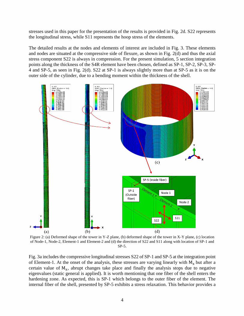
The deformed shape of the tower under the applied bending moment is shown in Fig. 2a and Fig.
2b, along with the longitudinal stresses S22. Fig. 2c presents a close-up view of the part of the
tower which experiences the highest compressive longitudinal stresses S22. The directions of the
4
stresses used in this paper for the presentation of the results is provided in Fig. 2d. S22 represents
the longitudinal stress, while S11 represents the hoop stress of the elements.
The detailed results at the nodes and elements of interest are included in Fig. 3. These elements
and nodes are situated at the compressive side of flexure, as shown in Fig. 2(d) and thus the axial
stress component S22 is always in compression. For the present simulation, 5 section integration
points along the thickness of the S4R element have been chosen, defined as SP-1, SP-2, SP-3, SP-
4 and SP-5, as seen in Fig. 2(d). S22 at SP-1 is always slightly more than at SP-5 as it is on the
outer side of the cylinder, due to a bending moment within the thickness of the shell.
Figure 2: (a) Deformed shape of the tower in Y-Z plane, (b) deformed shape of the tower in X-Y plane, (c) location
of Node-1, Node-2, Element-1 and Element-2 and (d) the direction of S22 and S11 along with location of SP-1 and
SP-5.
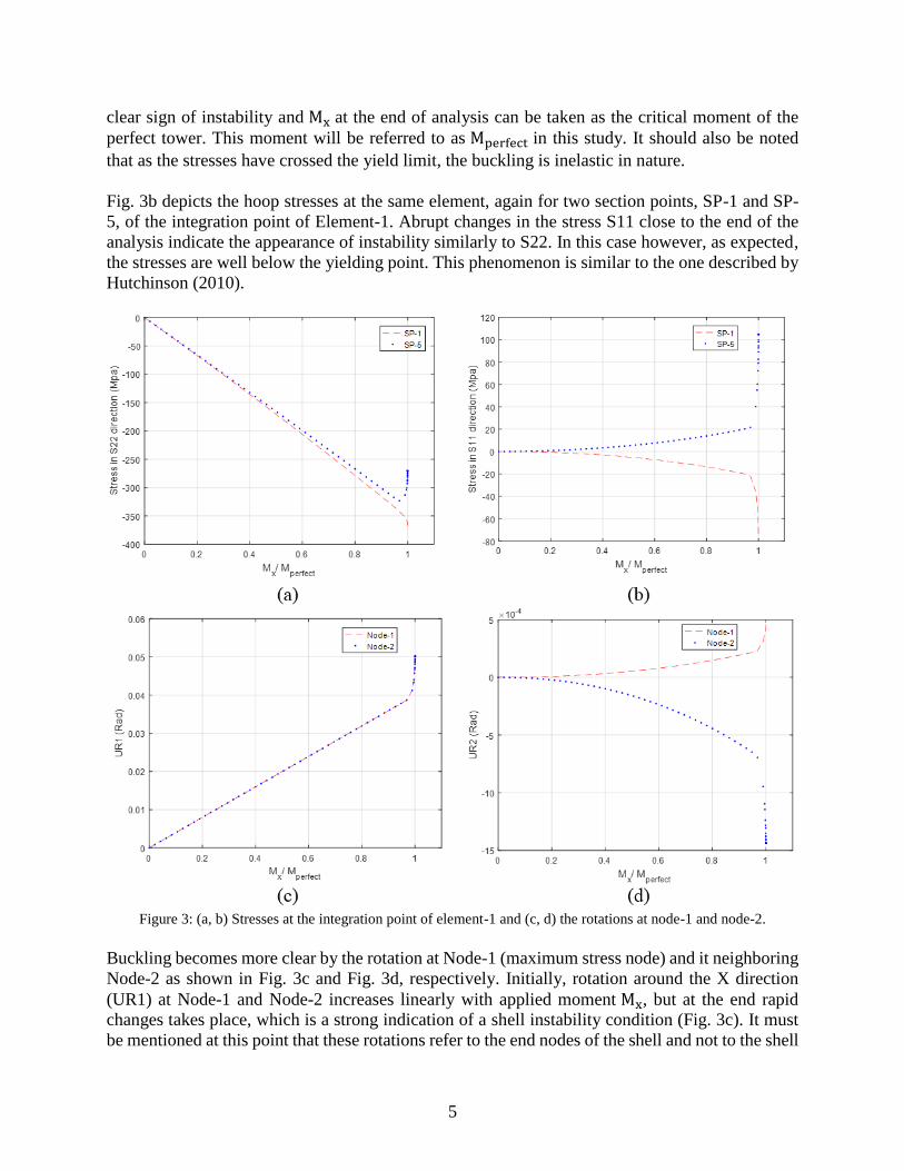
Fig. 3a includes the compressive longitudinal stresses S22 of SP-1 and SP-5 at the integration point
of Element-1. At the onset of the analysis, these stresses are varying linearly with Mx but after a
certain value of Mx , abrupt changes take place and finally the analysis stops due to negative
eigenvalues (static general is applied). It is worth mentioning that one fiber of the shell enters the
hardening zone. As expected, this is SP-1 which belongs to the outer fiber of the element. The
internal fiber of the shell, presented by SP-5 exhibits a stress relaxation. This behavior provides a
5
clear sign of instability and Mx at the end of analysis can be taken as the critical moment of the
perfect tower. This moment will be referred to as Mperfect in this study. It should also be noted
that as the stresses have crossed the yield limit, the buckling is inelastic in nature.
Fig. 3b depicts the hoop stresses at the same element, again for two section points, SP-1 and SP-
5, of the integration point of Element-1. Abrupt changes in the stress S11 close to the end of the
analysis indicate the appearance of instability similarly to S22. In this case however, as expected,
the stresses are well below the yielding point. This phenomenon is similar to the one described by
Hutchinson (2010).
Figure 3: (a, b) Stresses at the integration point of element-1 and (c, d) the rotations at node-1 and node-2.
Buckling becomes more clear by the rotation at Node-1 (maximum stress node) and it neighboring
Node-2 as shown in Fig. 3c and Fig. 3d, respectively. Initially, rotation around the X direction
(UR1) at Node-1 and Node-2 increases linearly with applied moment Mx, but at the end rapid
changes takes place, which is a strong indication of a shell instability condition (Fig. 3c). It must
be mentioned at this point that these rotations refer to the end nodes of the shell and not to the shell

6
integration points. Rotation around the Y direction (UR2) as shown in Fig. 3d also indicates an
instability condition close to the end of the analysis. UR2 at Node-1 and at Node-2 are in reverse
directions which implies an instability is taking place as this becomes suddenly close to the end of
the analysis.
It must be mentioned here that the location of the origin of the global coordinate systems results
in un-symmetric UR2 (rotation around the global Y axis) between Node-1 and Node-2. As shown
in Fig. 4, the origin of the x axis crosses Element-2 at a point which has a distance of 1/3 of the
element width from one of its edges. If the axis would be crossing in the middle of the element,
the UR2 rotation of Node-1 and Node-2 would be equal but opposite in signs.
Figure 4: Mesh and origin of axes.
3.2 Elastic Buckling Analysis of Perfect Tower
To introduce the geometric imperfections, the mode shapes of elastic buckling are utilized.
Eigenvalue analysis is performed using the linear perturbation method on the tower to get the
eigenvalues and mode shapes. The result of eigenvalue analysis is shown in Fig. 5 which includes
the eigenvalues of the first 100 modes. It can be seen that the first 100 eigenvalues are very close
to each other which is an expected behavior of thin cylindrical shells. Indicatively, the first 20
modes are within 12% of the first eigenvalue, the first 50 are within 22% of the first eigenvalue
and the first 100 eigenvalues lie between 30% of the first eigenvalue.
The shape of the eigenmodes is of great interest. The first modes include a longitudinal wrinkling
buckle-wave. As the mode number increases, the mode becomes more a combination of
longitudinal along with circumferential buckle-waves. For these first modes, buckling takes place
at the location where the 𝑅/𝑡 ratio is minimum (the shell is the “thinnest”), which is also an

7
expected behavior of cylindrical shells (NASA, 1965). In Fig.6c, the shape of the first six
eigenmodes is shown.
Figure 5: Variation of eigenvalues with eigenmodes
Figure 6: (a) First eigenmode of the tower, (b) variation of 𝑅/𝑡 along the height and (c) detailed view of the first six
eigemodes.
8
3.3 Nonlinear Static Analysis of the geometrically Imperfect Tower
To study the effect of geometric imperfections on the tower, imperfections are introduced in the
form of eigenmodes. First, the effect of imperfections in the form of individual modes has been
studied. Then, the effect of modes interaction has been studied, combining the first three and then
the first five modes. Combinations of more than five modes was not done due to the extensive
computational time required. For this particular study of this section, the amplitude of geometric
imperfections is taken as 𝑡/10 (t is the thickness of the shell at the location of the buckle-waves).
3.3.1 Geometric Imperfections in the Shape of Individual Modes
Geometric imperfections in the form of the first 50 mode shapes are introduced in the perfect tower
using ABAQUS command IMPERFCTION. Mode shapes are scaled such that the amplitude of
the imperfection is 𝑡/10. After the imperfections have been introduced, a nonlinear static analysis
is performed on the 50 imperfect towers.
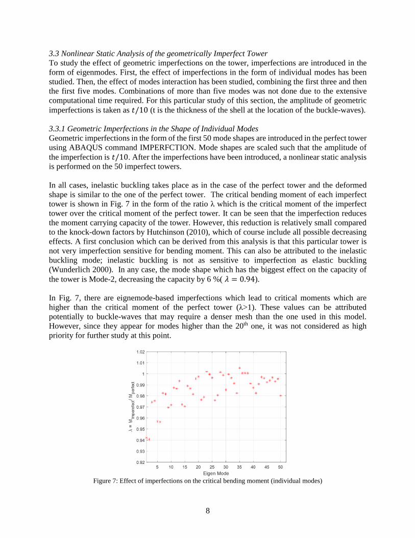
In all cases, inelastic buckling takes place as in the case of the perfect tower and the deformed
shape is similar to the one of the perfect tower. The critical bending moment of each imperfect
tower is shown in Fig. 7 in the form of the ratio λ which is the critical moment of the imperfect
tower over the critical moment of the perfect tower. It can be seen that the imperfection reduces
the moment carrying capacity of the tower. However, this reduction is relatively small compared
to the knock-down factors by Hutchinson (2010), which of course include all possible decreasing
effects. A first conclusion which can be derived from this analysis is that this particular tower is
not very imperfection sensitive for bending moment. This can also be attributed to the inelastic
buckling mode; inelastic buckling is not as sensitive to imperfection as elastic buckling
(Wunderlich 2000). In any case, the mode shape which has the biggest effect on the capacity of
the tower is Mode-2, decreasing the capacity by 6 %( 𝜆 = 0.94).
In Fig. 7, there are eignemode-based imperfections which lead to critical moments which are
higher than the critical moment of the perfect tower (λ>1). These values can be attributed
potentially to buckle-waves that may require a denser mesh than the one used in this model.
However, since they appear for modes higher than the 20th one, it was not considered as high
priority for further study at this point.
Figure 7: Effect of imperfections on the critical bending moment (individual modes)

9
3.3.2 Imperfection in the Shape of the First Three Modes Interaction
The effect of imperfections in the shape of combinations of the first three modes has also been
studied. The geometric imperfections in this case are defined by the following rule:
3
1
)10
(i
iiat
(1)
In this equation, 𝜙 is the imperfection vector expressed by nodal coordinates, 𝜙𝑖 is the normalized
𝑖𝑡ℎ mode and 𝑎𝑖 is the contribution of 𝑖𝑡ℎ mode which is chosen such that:
}1,75.0,50.0,25.0,0{
,13
1
i
i
i
a
a (2)
This constraint makes sure that the amplitude of the imperfection shape is always 𝑡/10. Although
infinite combinations are possible to satisfy this constraint if a continuous computation is selected,
due to the extensive computational time required, only five discrete values of 𝑎𝑖 are considered in
this study as shown in Eq. (2).
From these two constraints on 𝑎𝑖, a total of 15 different expressions for geometric imperfections
are generated using the first three modes. All these 15 shapes are introduced individually in-turn
and a nonlinear static analysis is performed. The results are shown in Table 1 arranged in
increasing order of ratio λ. It can be seen that the combination which contains only the second
mode leads again to the minimum value of critical the bending moment.
The unstable equilibrium is again found to be an inelastic buckling mode.
Table 1: Critical Bending Moment for interaction of the First 3 Modes
𝑎1 𝑎2 𝑎3 𝜆 =
𝑀𝑖𝑚𝑝𝑒𝑟𝑓𝑒𝑐𝑡
𝑀𝑝𝑒𝑟𝑓𝑒𝑐𝑡
0 1.00 0 0.940632
1.00 0 0 0.942105
0.25 0.75 0 0.956421
0 0.75 0.25 0.957053
0.75 0.25 0 0.957684
0.75 0 0.25 0.961053
0.50 0.50 0 0.963789
0 0.50 0.50 0.969263
0.25 0.50 0.25 0.971368
0.50 0.25 0.25 0.973474
0.50 0 0.50 0.973474
0 0.25 0.75 0.974316
0 0 1.00 0.974526
0.25 0.25 .50 0.9800
0.25 0 .75 0.980632

10
3.3.3 Imperfection in the Shape of the First Five Modes Interaction
The first five modes are also combined to look further for a worse geometric imperfection. The
formulation for the interaction is similar to the three mode combination, except that five modes
are used now instead of three. The imperfection 𝜙 in this case is defined as:
5
1
)10
(i
iiat
(3)
}1,75.0,50.0,25.0,0{
,15
1
i
i
i
a
a (4)
A total of 70 different shape imperfections have been generated and nonlinear static analysis is
performed. It is found that for this case imperfection Mode-2 leads again to the minimum critical
moment. From these studies, imperfection in the shape of Mode-2 seems to be the worst shape
imperfection for this specific tower geometry.
3.3.4 Mechanism of Collapse of Mode 2 Shape Imperfect Tower
Detailed analysis of the results around the region which contains the nodes with maximum stresses
has been done for the case of the imperfect tower as well.
Stresses at the integration point of Element-1 are shown in Fig. 8a and in Fig. 8b. Fig. 8a includes
the longitudinal stresses S22 of SP-1 and SP-2 at the integration point of Element-1. This element
is located at the compressive side of flexure and thus the axial component S22 is always in
compression. Initially, S22 is varying linearly with 𝑀𝑥 but after a certain value of 𝑀𝑥 abrupt
changes take place and finally analysis stops at 𝑀𝑥 = 0.9406𝑀𝑝𝑒𝑟𝑓𝑒𝑐𝑡 due to negative
eigenvalues (again static general is applied). Abrupt changes in S11 are also taking place
demonstrating the same instability mode (Fig. 8b). These are the clear sign of instability and 𝑀𝑥
at the end of analysis can be taken as the critical bending moment.
Figure 8: (a) Stress S22 at SP-1 and SP-5 at the integration point of Element-1 and (b) S11 stresses at the same
points
11
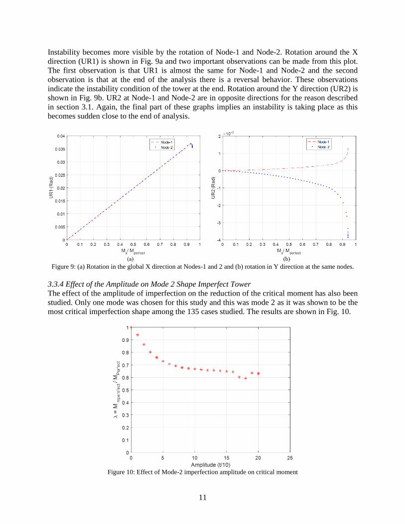
Instability becomes more visible by the rotation of Node-1 and Node-2. Rotation around the X
direction (UR1) is shown in Fig. 9a and two important observations can be made from this plot.
The first observation is that UR1 is almost the same for Node-1 and Node-2 and the second
observation is that at the end of the analysis there is a reversal behavior. These observations
indicate the instability condition of the tower at the end. Rotation around the Y direction (UR2) is
shown in Fig. 9b. UR2 at Node-1 and Node-2 are in opposite directions for the reason described
in section 3.1. Again, the final part of these graphs implies an instability is taking place as this
becomes sudden close to the end of analysis.
Figure 9: (a) Rotation in the global X direction at Nodes-1 and 2 and (b) rotation in Y direction at the same nodes.
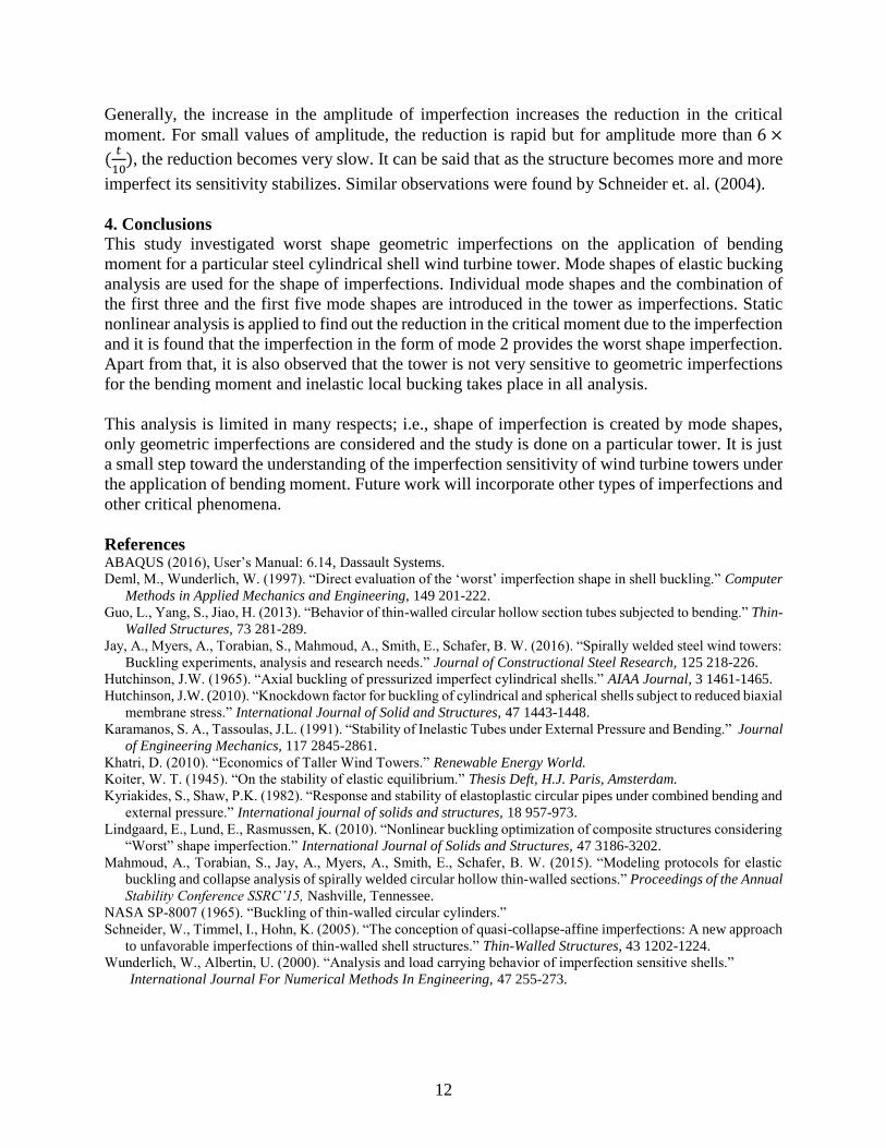
3.3.4 Effect of the Amplitude on Mode 2 Shape Imperfect Tower
The effect of the amplitude of imperfection on the reduction of the critical moment has also been
studied. Only one mode was chosen for this study and this was mode 2 as it was shown to be the
most critical imperfection shape among the 135 cases studied. The results are shown in Fig. 10.
Figure 10: Effect of Mode-2 imperfection amplitude on critical moment
12
Generally, the increase in the amplitude of imperfection increases the reduction in the critical
moment. For small values of amplitude, the reduction is rapid but for amplitude more than 6 ×
(𝑡
10), the reduction becomes very slow. It can be said that as the structure becomes more and more
imperfect its sensitivity stabilizes. Similar observations were found by Schneider et. al. (2004).
4. Conclusions
This study investigated worst shape geometric imperfections on the application of bending
moment for a particular steel cylindrical shell wind turbine tower. Mode shapes of elastic bucking
analysis are used for the shape of imperfections. Individual mode shapes and the combination of
the first three and the first five mode shapes are introduced in the tower as imperfections. Static
nonlinear analysis is applied to find out the reduction in the critical moment due to the imperfection
and it is found that the imperfection in the form of mode 2 provides the worst shape imperfection.
Apart from that, it is also observed that the tower is not very sensitive to geometric imperfections
for the bending moment and inelastic local bucking takes place in all analysis.
This analysis is limited in many respects; i.e., shape of imperfection is created by mode shapes,
only geometric imperfections are considered and the study is done on a particular tower. It is just
a small step toward the understanding of the imperfection sensitivity of wind turbine towers under
the application of bending moment. Future work will incorporate other types of imperfections and
other critical phenomena.
References ABAQUS (2016), User’s Manual: 6.14, Dassault Systems.
Deml, M., Wunderlich, W. (1997). “Direct evaluation of the ‘worst’ imperfection shape in shell buckling.” Computer
Methods in Applied Mechanics and Engineering, 149 201-222.
Guo, L., Yang, S., Jiao, H. (2013). “Behavior of thin-walled circular hollow section tubes subjected to bending.” Thin-
Walled Structures, 73 281-289.
Jay, A., Myers, A., Torabian, S., Mahmoud, A., Smith, E., Schafer, B. W. (2016). “Spirally welded steel wind towers:
Buckling experiments, analysis and research needs.” Journal of Constructional Steel Research, 125 218-226.
Hutchinson, J.W. (1965). “Axial buckling of pressurized imperfect cylindrical shells.” AIAA Journal, 3 1461-1465.
Hutchinson, J.W. (2010). “Knockdown factor for buckling of cylindrical and spherical shells subject to reduced biaxial
membrane stress.” International Journal of Solid and Structures, 47 1443-1448.
Karamanos, S. A., Tassoulas, J.L. (1991). “Stability of Inelastic Tubes under External Pressure and Bending.” Journal
of Engineering Mechanics, 117 2845-2861.
Khatri, D. (2010). “Economics of Taller Wind Towers.” Renewable Energy World.
Koiter, W. T. (1945). “On the stability of elastic equilibrium.” Thesis Deft, H.J. Paris, Amsterdam.
Kyriakides, S., Shaw, P.K. (1982). “Response and stability of elastoplastic circular pipes under combined bending and
external pressure.” International journal of solids and structures, 18 957-973.
Lindgaard, E., Lund, E., Rasmussen, K. (2010). “Nonlinear buckling optimization of composite structures considering
“Worst” shape imperfection.” International Journal of Solids and Structures, 47 3186-3202.
Mahmoud, A., Torabian, S., Jay, A., Myers, A., Smith, E., Schafer, B. W. (2015). “Modeling protocols for elastic
buckling and collapse analysis of spirally welded circular hollow thin-walled sections.” Proceedings of the Annual
Stability Conference SSRC’15, Nashville, Tennessee.
NASA SP-8007 (1965). “Buckling of thin-walled circular cylinders.”
Schneider, W., Timmel, I., Hohn, K. (2005). “The conception of quasi-collapse-affine imperfections: A new approach
to unfavorable imperfections of thin-walled shell structures.” Thin-Walled Structures, 43 1202-1224.
Wunderlich, W., Albertin, U. (2000). “Analysis and load carrying behavior of imperfection sensitive shells.”
International Journal For Numerical Methods In Engineering, 47 255-273.