ON THE DYNAMIC BEHAVIOR OF SERIES HYDRAULIC HYBRID VEHICLE
16
Journal of Al Azhar University Engineering Sector Vol. 13, No. 48, July 2018, 930-945 ON THE DYNAMIC BEHAVIOR OF SERIES HYDRAULIC HYBRID VEHICLE M. Gomaa Abu Alnagah 1 , M. Elfaisal El-Refaie 1 and M. Galal Rabie 2 1 Mechanical Power engineering department, Al-Azhar University, Cairo, Egypt 2 Manufacturing Engineering department, Modern Academy for Engineering and Technology in Maadi , Cairo, Egypt ملخص: حتشاق انذاخهاسطت يحشكبث ايكيت بيكب ان انطبلبئهت ي يتخهفبث كبث انف يثم يشكبل يتعذدة ان انثميهتبثشكبتج ان ت. نزا فأبحكب انذ انضغط عهحيطت ع نهبيئت انكم حشاس شب عه يتى فمذ انطبلتز يعظى. صب فبسخصعتب ادة تأخز ففم انطبلت انز تكشسف انليبساث راث ان انس. بيجاسطت بش بنيكيذس ظبو يىث يمتشح نتصزا انبح يمذو( automation studio ) . اكبث يشكب ان فظبو انذفع انتمهيذ يعذل ادائتض ف خف بذيكيكبظبو انبئص انفس خص يحمك بحيث انيكيذسظبو انزا انذل ب يستب, يحمك رنك انضبفب بحمب يشة اخش باعبدة استخذاي حبنت انفشيهت فدفم ان انطبل تخزي ظبوزا ان يسبسذف ا ان. ايضبزا انبحث يتض يذسظبو ان نبس يع– انتمهيذيكيكبظبو ان بعذ تعذيم انبتف يكصيزنك تك يكيكب ي. اسطتو بظبزا ان نم يحبكب تى ع( MATLAB/SIMULINK ) . هفت يختت حشكتظ هفتف يختذ ظش ع تى فحصشكبت اداء ان. ABSTRACT High Stopping frequency of heavy vehicles such as refuse trucks produces a large amount of energy which is generated by driving engine during vehicle acceleration. Most of this energy is wasted in form of heat to the environment when the vehicle brakes. This wasted energy normally lost during braking is significant especially in repeated stopping vehicles. This research presents a concept for the hydraulic hybrid system design using automation studio software to build the suggested hydraulic circuit. The classical mechanical traction in traditional vehicle can be replaced by this system without lowering vehicle performance and other satisfaction criteria in addition to achieving the main target from hybridization; regenerate energy which is always lost during vehicle braking and reuse to accelerate it again. It also includes the hydro- mechanical system architecture (which is called SHHS) and its component specification after changes in traditional vehicle structure. The switching matrix for control unit also illustrated. In this paper, the dynamics model for the SHHS (Series hydraulic hybrid vehicle) is constructed by MATLAB/SIMULINK package. The vehicle performance is investigated during various modes of operation at different condition. Key Words: hybrid vehicle, Series hydraulic hybrid system, MATLAB/SIMULINK, automation studio, energy regeneration, accumulator.
Transcript of ON THE DYNAMIC BEHAVIOR OF SERIES HYDRAULIC HYBRID VEHICLE

Journal of Al Azhar University Engineering Sector
Vol. 13, No. 48, July 2018, 930-945
ON THE DYNAMIC BEHAVIOR OF SERIES HYDRAULIC HYBRID
VEHICLE
M. Gomaa Abu Alnagah1, M. Elfaisal El-Refaie
1 and M. Galal Rabie
2
1 Mechanical Power engineering department, Al-Azhar University, Cairo, Egypt
2 Manufacturing Engineering department, Modern Academy for Engineering and Technology in
Maadi , Cairo, Egypt
:ملخصنزا فأ .تتج انشكببث انثميهت يتعذدة انلف يثم يشكببث انخهفبث كيت بئهت ي انطبل انيكبيكيت باسطت يحشكبث الاحتشاق انذاخه
ز انطبلت انفمدة تأخز ف الاعتببسخصصب ف .يعظى ز انطبلت يتى فمذب عه شكم حشاس نهبيئت انحيطت عذ انضغط عه انكببح
.انسيبساث راث انلف انتكشس
ظبو انذفع انتمهيذ ف انشكببث يك ا .( automation studio)يمذو زا انبحث يمتشح نتصيى ظبو يذسنيك باسطت بشبيج
ببلاضبف ان رنك يحمك ,يستبذل بزا انظبو انيذسنيك بحيث ا يحمك فس خصبئص انظبو انيكبيك بذ خفض ف يعذل ادائت
زا انبحث يتض ايضب .انذف الاسبس ي زا انظبو تخزي انطبل انفمد ف حبنت انفشيهت اعبدة استخذايب لاحمب يشة اخش
. ييكبيك كزنك تصيف يكبت بعذ تعذيم انظبو انيكبيك انتمهيذ –يعبس نظبو انيذس
.اداء انشكبت تى فحص عذ ظشف يختهفت لاظت حشكت يختهفت.( MATLAB/SIMULINK)تى عم يحبكب نزا انظبو باسطت
ABSTRACT High Stopping frequency of heavy vehicles such as refuse trucks produces a large amount of energy which
is generated by driving engine during vehicle acceleration. Most of this energy is wasted in form of heat to
the environment when the vehicle brakes. This wasted energy normally lost during braking is significant
especially in repeated stopping vehicles.
This research presents a concept for the hydraulic hybrid system design using automation studio software
to build the suggested hydraulic circuit. The classical mechanical traction in traditional vehicle can be
replaced by this system without lowering vehicle performance and other satisfaction criteria in addition to
achieving the main target from hybridization; regenerate energy which is always lost during vehicle
braking and reuse to accelerate it again. It also includes the hydro- mechanical system architecture (which
is called SHHS) and its component specification after changes in traditional vehicle structure. The
switching matrix for control unit also illustrated.
In this paper, the dynamics model for the SHHS (Series hydraulic hybrid vehicle) is constructed by
MATLAB/SIMULINK package. The vehicle performance is investigated during various modes of
operation at different condition.
Key Words: hybrid vehicle, Series hydraulic hybrid system, MATLAB/SIMULINK, automation
studio, energy regeneration, accumulator.

ON THE DYNAMIC BEHAVIOR OF SERIES HYDRAULIC HYBRID VEHICLE
1. INTRODUCTION: Normally, the traditional vehicle is mechanized with an internal combustion engine (ICE) using fuels to
generate the power. The power is transmitted to the tires via a mechanical drive train. During a vehicle
deceleration, the necessary braking torque will be applied to reduce the vehicle velocity to meet the
requirement of brake criteria. As a consequence, the vehicle’s kinetic and mass potential energy is
dissipated via a friction braking as a form of heat. This wasted energy is significant, especially in high
stop and go frequency vehicles.
Nowadays, one of the world important problems is increase of the oil demand and consuming the most of
oil sources. Due to this reason, improving the fuel consumption in transportation sector contributes to
improve the national economic aspects. The trend of vehicle ownership is nearly 1000 million passenger
cars and 300 heavy duty vehicles which consume about 38 million barrels of crude oil per day for road
transportation system [1]
Besides the development of new technologies in automotive to improve the vehicle’s safety, comfort and
* Assistant, Mechanical Power engineering department, Al-Azhar University, Cairo, Egypt
** Professor, Manufacturing Engineering department, Modern for Engineering and Technology
in Maadi , Cairo, Egypt
*** Professor, Mechanical Power engineering department, Al-Azhar University, Cairo, Egypt assist systems for driver, steering systems, application of turbochargers in diesel engines and using electric
energy as direct prime mover, scientific efforts have been made to reduce energy consumption by
reducing fuel or energy consumption. Hybrid vehicle system is one of these efforts. This system is applicable to traditional vehicles with some
modifications; some changes in the vehicle structure.
When an additional power source is added to the traditional vehicle, it is called a “hybrid” [2,4]. The
hybrid word comes from the Latin language and means: “mixed, having two sources”. Normally, one
source converts the fuel in to energy while another source is a storage unit. The additional power source
may be electrical, chemical, hydraulic and mechanical or any other form of power storage and extraction.
Hydraulic Hybrid Vehicles (HHVs) are one of new energy saving technologies, which are developed by
vehicle manufacturers (like ford, Toyota and others), universities researchers and research centers.
There are many kinds of hybrid vehicle technology [3,4and 5], according to power source there are:
gasoline/ hydraulic (hydraulic hybrid),
gasoline/ mechanical (mechanical hybrid),
gasoline/ electric (electric hybrid),
Fuel cell/ battery (fuel cell hybrid), etc.
The development of hybrid vehicle systems especially in last ten years can be classified in to two major
branches:
Electric hybrid vehicles (EHV).
Hydraulic hybrid vehicles (HHV).
Nowadays, competitive advantages between these two branches are hard. There are some similarities
and differences between them [6,7]. It is necessary in hybrid vehicle systems to state some
characteristics of storing energy element in the used secondary power source [8].
Hydraulic hybrid Vehicles are known by vehicles manufactures under several names such as, Mild
hydraulic hybrid vehicle by American Environmental protection Agency (EPA), Hydraulic Lunch
Assist (HLA) by Eaton Corporation, Hydraulic Regenerative Braking (HRB) system by Bosch, and at
last but not least hydraulic power assist by Ford Motor Company or in general hydraulic hybrid vehicle. Hydraulic Launch Assist System (HLA) had been developed by Eaton; the Eaton’s system has two modes of operation; performance mode and economy mode. In economy mode, accumulator power only is used to start up the vehicle while accumulator and engine power are used to start up the vehicle in performance mode. HLA system is applied on Peterbit 320 refuse truck, the results show17% to 28% in fuel saving in performance and economy modes respectively. Results also indicate that, about 70% of

ON THE DYNAMIC BEHAVIOR OF SERIES HYDRAULIC HYBRID VEHICLE
available kinetic energy during braking can be regenerated .This regenerated energy can accelerate the vehicle faster than the traditional vehicle about 2% and 26% in economy and performance modes respectively [9]. Parallel Hydrostatic Regenerative Braking system (HRB) was installed by Bosch-Rexroth on LET2 Truck (Crane Carrier Company) and was tested by New York City Department of Sanitation (DSNY) [BR14d]. This system had been applied later in 2011 on Mack garbage truck. According to the behavior of driver and used driving cycle, these truck stops about 800 times. About 25% reduction in fuel consumption by truck was saved [10]. The hydraulic regenerative system for a bicycle was investigated by Koustubh Dinesh Lagwankar . [11]. Some modification can be applied to the bicycle to reduce amount of human effort, a hydraulic hybrid system can be added to the traditional bicycle which can store the energy lost during braking and reuse it during accelerating the bicycle. Based on Matlab / Simulink, Simulation was carried out at the following conditions: the bicycle velocity was 40 km/ hr, the total weight included bicycle and rider was 100 kg, Gear ratio is (3) and the bladder type accumulator was used (4 liter capacity) and charging pressure of 72 bar. it was noted that about 92% of bicycle kinetic energy can be stored in the hydraulic accumulator. The amount of saved human effort makes it worth one’s while in real life but the system was costly; the system cost was high, it can cost triple compared to traditional bicycle. But with help of further development and research in the same area this cost can be lowered to an economical value. 2. SYSTEM DESCRIPTION: In series hydraulic hybrid vehicle; pure hydrostatic systems, is replaces the conventional transmission and drive shaft to a hydraulic system .shown in Figure 1.The hydraulic pump which is directly connected to the prime mover (normally ICE), converts the engine power output to hydraulic power. The pressurized hydraulic fluid then may charge the accumulator or directly flow to the hydro-motor (via a control unit) which is coupled to the vehicle wheel to propel it. This arrangement allows the engine runs at the best efficiency region in its engine map. In additionally, when the vehicle partially or completely decelerating, the engine may be turned off. The main components of the proposed concept structure include components like Hydraulic reservoir, hydraulic fluid filter, Hydraulic pump, hydraulic motor, Direction control Valve, Hydraulic accumulator and pressure relief valve [12]. 3.SYSTEM OPERATION:
Complete ride of vehicle can be classified in 4 basic modes like idling mode, running mode (extended Acceleration mode, light acceleration mode and reverse motion mode), regenerative braking mode and power saving mode. These various modes can be obtained with the help of actuation of directional control valves in the hydraulic circuit. In case of non-operating mode, the system components are non-activated as shown in fig. 2. In case of idling mode the pump (P1) is bypassed to tank; the pump (P1) sucks the hydraulic oil from the oil tank (T) through DCV1 and sends it again to the tank. The selected path gives us minimum resistance path and hence the amount of energy which is lost during this process is minimum value. In running mode, the power which is generated by the engine is directly used to accelerate the vehicle. During this mode, engine power is given as an input to the hydraulic pump (P1). Hydraulic pump P1 has converted the mechanical energy into hydraulic fluid energy to drive hydro- motor M which in turn converts hydraulic energy back to mechanical energy to propel the vehicle tires through DCV1 and DCV3 (The hydro- motor is coupled to the rear wheel of the vehicle). In this case, Acc is isolated from this system .while P2 is bypass to the tank .This process is controlled according to torque and speed required.as shown in Fig.3.This mode also called cruising mode. In case of reverse motion mode, this mode likes running mode except the motor (M) running in the reverse direction. In case of regenerative braking, the pump uses the momentum of the vehicle to pressurize fluid from the reservoir and stores it in the accumulator. When the vehicle is going to brake, pump (P1) is isolated and pump (P2) uses the momentum of the vehicle to pressurize fluid from the reservoir (T) through DCV4 and stores it in hydraulic accumulator (ACC) as shown in Fig.4. This pressurized fluid is used to accelerate the

ON THE DYNAMIC BEHAVIOR OF SERIES HYDRAULIC HYBRID VEHICLE
vehicle later. This process captures and reuses the energy normally lost during braking. If the accumulator is fully charged, excess quantity of pressurized fluid will pass through pressure relief valve (PRV2) and flow into the tank (energy lost in RV). In case of light acceleration, the drive motor (M) uses high pressurized fluid stored previously in high pressure accumulator (ACC) throughDCV2 and DCV3 to rotate the vehicle wheels as accelerator pedal has been pressed. The hydraulic fluid which has been used to rotate the vehicle wheels is then at a lower pressure and return into the reservoir again. In case of extended cruising (Heavy Acceleration), the motor provides power by accumulator fluid to drive the wheel in addition of using the engine power. This process reduces the engine power needed to accelerate powerfully and quickly and so saving fuel. In case of power saving mode (a), the engine will turn on and begin to take fluid from the reservoir, pressurize it and transfer the fluid to the motor. Any excess high pressure fluid from the master pump not needed by the drive hydro- motor will be stored in the hydraulic accumulator.
Fig. 1. Configuration of series hydraulic hybrid system Fig.2.schematic for proposed Hydraulic Circuit
fig.3.cruising mode Fig.4. Regenerative braking mode
In case of Power saving mode (b), the power required is zero so the generated power stored as a form in
pressure in accumulator. In this mode the pump (P1) sucks the oil from the oil reservoir (T) and sends it to

ON THE DYNAMIC BEHAVIOR OF SERIES HYDRAULIC HYBRID VEHICLE
the accumulator (ACC) through DCV1 and NRV. After complete filling of accumulator the excess oil is
drained to the reservoir (T) through pressure relief valve (PRV1).
The direction of flow and components interplaying (DCVS and Engine) in different modes of operation
are shown in table1.
4. VEHICLE SPECIFICATIONS:
The truck chosen to be studied as arepresentative model is a Peterbilt 320 [13] with a 25 rear loading
Refuse truck body. This truck was selected based on vehicle usage, commercial availability, and the
availability of data. The vehicle geometrical parameters are summarized in Table 2.
Table.1. Valve Actuation for different modes Table.2. Baseline vehicle parameters
Modes S1 S2 S3 S4 S5 S6 E
Non- operating 0 0 0 0 0 0 0
Idling 0 0 0 0 0 0 1
Running 0 1 1 1 0 0 1
Regenerative
Braking
0 0 1 0 0 1 0
Light acceleration 0 0 0 1 0 0 0
Heavy acceleration 0 1 0 1 0 0 1
Reverse motion 0 1 1 0 1 0 1
Power saving (a) 0 1 0 1 0 0 1
Power saving (b) 1 0 1 0 0 0 1
Note: (1) Activated; (0) Deactivated
Parameter Value
Tare Weight (kg) 15000
GVWR (kg) 25500
Height (m) 3.58
Width (m) 2.438
Tire Diameter (m) 1
Differential Ratio 5.38
Transmission
Ratios
12.8, 9.25, 6.76, 4.90, 3.58,
2.61, 1.89, 1.38, 1.00, 0.73
5. Vehicle Model: The vehicle was modeled to predict the road loads of the vehicle. When a vehicle is in motion, different
forces are acting upon it. To initiate and maintain vehicle motion, a thrust force is required at the tires.
This force is usually defined as the tractive force ( ), which is required to overcome resisting forces
during vehicle motion. These forces typically include aerodynamic drag ( ), rolling resistance ( ),
loads due to a grade ( , and inertia force ( )[14] as shown in the free body diagram of Fig.5.
= (1)
The inertia force is equal to vehicle mass multiplied by the vehicle acceleration.
Where, m is vehicle mass , is vehicle velocity and acceleration respectively.
(2)
= (3)
The aerodynamic resistance of the vehicle requires knowledge of the frontal area of the vehicle ( ),
drag coefficient ( ), air density ( ), and vehicle speed ( ).
The density of air was assumed to be 1.2 kg/ .The drag coefficient was assumed to be 0.8.
= m g sin (4)

ON THE DYNAMIC BEHAVIOR OF SERIES HYDRAULIC HYBRID VEHICLE
Fig.5. Free body diagram of the longitudinal dynamic forces acting on a vehicle
The rolling resistance of the vehicle ( ) is calculated using Equation:
= m g cos where, is grade angle (5)
Based on experimental results, many empirical formulas have been proposed for calculating the rolling
resistance coefficient ( ) of tires on hard surfaces [15]
= 0.006 + 0.23 * (6)
In this empirical formula (Eq. 6), vehicle speed is specified in units of km/h.
The power required at the wheel’s axles is,
= . (7)
The dynamic behavior of the vehicle traction system is described by Eqs. 1-7. These equations were used to develop a computer simulation program using the MATLAB (SIMULINK) package, This model shown in Fig .6., was built to calculate Load forces as well as the demand power that was required to overcome the resistance forces are shown in Figures at different condition (different mass, different Grade angles). At maximum unloaded vehicle speed of 86 km/hr, power required at the wheels is about 80 kW at zero grade angles, as shown in the fig.7. According to New York Garbage Truck driving Cycle, in case of fully loaded vehicle at zero grade angles the maximum vehicle speed is 32 km/hr (20 mph). Simulation results of the vehicle dynamics model including load force and load torque as well as the load power required at wheels to overcome the resistance forces at different grade Angeles are indicate that, the maximum torque (63000 Nm at 30 degree grade angle) for which the drivetrain must designed.
Fig.6. simulation program of the vehicle

ON THE DYNAMIC BEHAVIOR OF SERIES HYDRAULIC HYBRID VEHICLE
Fig.7. Road load force and power at the unloaded vehicle speed range
6. COMPONENTS SPECIFICATIONS:
The requirements of the hydro-mechanical system components are based upon the vehicle requirements.
In order to choose these components (size and ratios design) the demands of the drive must be specified
(maximum vehicle speed and maximum torque required). The pump and hydro-motor selection depends
on the state of the art pump catalogue data sheet of Bosch Rexroth [16]. Based on the above analysis final
component specification which can perform the task is listed in Table .3.
7. Dynamic behavior during operating mode:
To study the system performance, plausible system operating modes are considered, included Running,
Light accelerating, Regenerative braking, and Power saving mode. Different working conditions have
been conducted to investigate the effect of component parameter
Table .3.Component specifications
Item Type Displacement
[ ]
Max. speed
[rpm]
Max .Torque
[N.m]
Transmission
Ratio
I
Pump A4VSO 355 1700 1976 ---
Motor A2FE 160 3600 1021 ---
Pump mount Spur gear --- --- --- 1.42
Motor final drive Spur gear (2
speed ratio)
--- --- --- 1.38&12.8
Differential --- 5.38
Figures 8, 9 present a simplified schematic of the system during running and regenerative braking modes.

ON THE DYNAMIC BEHAVIOR OF SERIES HYDRAULIC HYBRID VEHICLE
Fig.8.Schematic diagram of system in running mode Fig.9.Schematic diagram of system in
Regenerative braking mode
8. MATHEMATICAL MODEL &SIMULATION PROGRAM:
The pre described modes are represented by the following equations:
Flow rate through the direction control valves:
= (8)
= (9)
= (10)
(11)
Where,
is P - A pass resistance in DCV1, R= 1.0512*10^10 kg/m7
is P - B pass resistance in DCV3, R= .77*10^10 kg/m7
is P - A pass resistance in DCV4, R= 1.0512*10^10 kg/m7
is A-T pass resistance in DCV3, R= .777*10^10 kg/m7
Continuity equations:
(12)
(13)
(14)
(15)
(16)
(17)
Where,
ON THE DYNAMIC BEHAVIOR OF SERIES HYDRAULIC HYBRID VEHICLE
Flow rate through DCV1
Flow rate through DCV3
Flow rate through DCV3 in return pass
Flow rate through the DCV4
Pressure at DCV3 exit
Pressure at motor exit
Pressure at DCV3 exit in return direction
Pressure at DCV4 exit
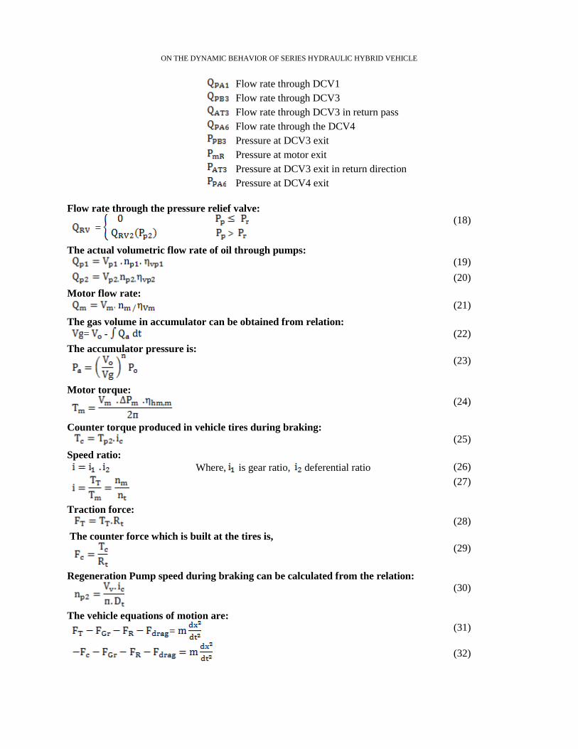
Flow rate through the pressure relief valve:
= (18)
The actual volumetric flow rate of oil through pumps: (19)
(20)
Motor flow rate:
(21)
The gas volume in accumulator can be obtained from relation:
= - (22)
The accumulator pressure is:
(23)
Motor torque:
(24)
Counter torque produced in vehicle tires during braking:
(25)
Speed ratio:
Where, is gear ratio, deferential ratio (26)
(27)
Traction force:
(28)
The counter force which is built at the tires is,
(29)
Regeneration Pump speed during braking can be calculated from the relation:
(30)
The vehicle equations of motion are:
= (31)
(32) (5.27)

ON THE DYNAMIC BEHAVIOR OF SERIES HYDRAULIC HYBRID VEHICLE
The dynamic behaviors of the vehicle traction system during the modes of operation are described by
equations 8-32. These equations were used to develop a computer simulation program using the
MATLAB (SIMULINK) package. The numerical values of the construction parameter of the system were
found out in the data sheets of the elements.
9. SIMULATION RESULTS:
There are some assumptions made to build the required model. For example, mechanical efficiency is 95%
and hydraulic efficiency is 100%. The charging and discharging processes of accumulator are assumed to
be polytropic. The oil compressibility is ignored in DCV4- accumulator pass with respect to gas
compressibility in accumulator and also ignoring cracking pressure in check valve
Simulation is done considering the following conditions: the longitudinal velocity of the vehicle is 86
km/hr at unloaded (The total weight of vehicle is15000 kg) and 36 km/hr at fully loaded (The total weight
of vehicle is 25500 kg), Gear ratio is 7.424 and accumulator volume is 70 liter.
Figures 10, 11 and12 show the effect of pump displacement on the vehicle speed, motor torque and pump
power at different load (unloaded, partially loaded and fully loaded), as pump displacement increases the
vehicle speed at different mass also increases as a consequence the required power increases too. The
higher vehicle mass will offer high resisting torque since it requires more power to operate.
From Figs.; 13 and 14, the motor torque as well as required pump power increase as vehicle mass
increases at the same pump displacement (vehicle speed considered constant), in another way both the
motor torque and successively pump power also increase when pump displacement increases at the same
vehicle mass.
Fig.10.Effect of pump displacement on unloaded vehicle
Fig.11.Effect of pump displacement on partially loaded vehicle

ON THE DYNAMIC BEHAVIOR OF SERIES HYDRAULIC HYBRID VEHICLE
Fig.12.Effect of pump displacement on fully loaded vehicle
Fig.13.Effect of pump displacement in motor torque at different vehicle mass
Fig.14.Effect of pump displacement in pump power at different vehicle mass
From Fig.15, we can see that as braking occurs, the vehicle energy is divided in various ways some of this
energy captured again and store in accumulator which is denoted by (Eacc), the rest energy is lost to
overcome drag force which is denoted by (Ed), rolling resistance force which is denoted by (ER) and

ON THE DYNAMIC BEHAVIOR OF SERIES HYDRAULIC HYBRID VEHICLE
mechanical losses (Ep minus Eacc) and energy lost in relief valve which is denoted by (ERV=0 in this
case). It can be also noted that nearly 76% of lost energy during braking can be captured and restored in
the accumulator.
Figure16 shows the effect of pump displacement on the braking time. As the pump displacement increased
the vehicle brake faster; time required to stop the vehicle will be lesser and vice versa; the pump with
lower displacement causes larger time to stop the vehicle.
During this braking period the vehicle kinetic energy is lost and restored faster as the pump displacement
increases and vice versa, shown in Figs .17 and 18.
Figure18. also illustrate that, the same amount of energy can be captured by accumulator at different time
according to pump displacement.
The higher pump displacement will produce high resisting torque. Due to this, deceleration will be faster.
On otherwise the lower pump displacement will get less torque at long time; lower deceleration, this is
shown in Fig .19. If the displacement is not large enough, the generated braking torque is insufficient to
stop the vehicle in braking time.
Fig.15. Energy balance during braking
Fig.16. Effect of pump displacement on vehicle velocity
Figures20and 21, illustrate effect of accumulator charging pressure on vehicle velocity and braking
torque. At (250 cc/rev) pump displacement at different accumulator charging pressure we can see that if
the pre-charging pressure increases the vehicle decelerates faster due to faster generated braking torque.

ON THE DYNAMIC BEHAVIOR OF SERIES HYDRAULIC HYBRID VEHICLE
Fig.17. Effect of pump displacement on energy lost during braking
Fig.18. Effect of pump displacement on energy stored
Fig.19. Effect of pump displacement on braking torque

ON THE DYNAMIC BEHAVIOR OF SERIES HYDRAULIC HYBRID VEHICLE
Fig.20. Effect of accumulator charging pressure on vehicle velocity
Fig.21. Effect of accumulator charging pressure on braking torque
10. CONCLUSION
In this search, the classical mechanical drive train in traditional vehicle is replaced by pure hydraulic
system. the automation studio software is used to design the proposed hydraulic circuit .The effect of
system components involved in regenerative braking and running operating modes (such as vehicle mass,
pump displacement, regeneration pump size and accumulator charging pressure) has been investigated.
The Simulation program for these modes has been built using MATLAB /SIMULINK package.
Simulation results indicated that, the braking time is variable according to regeneration pump
displacement .also the accumulator volume and charging pressure mainly effected in braking torque and
hence braking time. And also 70 liter accumulator volume at pressure range from 100 to 350 bar is used;
nearly 76% of braking energy normally lost can be captured in accumulator and reuse later to drive the
vehicle.
Nomenclature: Symbol Definition Unit Symbol Definition Unit
QP1 Master Pump flow rate m3/s Pressure at DCV3 exit Pa
QP2 Regeneration Pump flow rate m3/s Pressure at motor exit Pa
Vp1 Master Pump geometric volume m3/rev Pressure at DCV3 exit in return direction Pa
Vp2 Regeneration Pump geometric volume m3/rev Pressure at DCV4 exit Pa
Pp1 Master pump pressure Pa P - A pass resistance in DCV1 kg/m7
Pp2 Regeneration Pump pressure Pa P - B pass resistance in DCV3 kg/m7

ON THE DYNAMIC BEHAVIOR OF SERIES HYDRAULIC HYBRID VEHICLE
Master Pump speed Rpm A- T pass resistance in DCV3 kg/m7
Regeneration Pump speed Rpm P - A pass resistance in DCV4 kg/m7
Torque required to operate the master pump N.m Qa accumulator flow rate m3/s
Torque required to operate the Regeneration
Pump
N.m Tc Counter torque produced in tires
N.m
Master Pump volumetric efficiency -- Fc Counter force produced in tires N
Regeneration Pump volumetric efficiency -- TT Traction torque N.m
Motor mechanical efficiency -- Pa Accumulator pressure Pa
motor hydraulic efficiency --
Po Accumulator charging pressure, gas
pressure
Pa
motor volumetric efficiency -- Vo Volume of gas at pressure Po m3
motor flow rate m3/s Vg Volume of gas at pressure P m3
motor geometric volume m3/rev Vehicle mass Kg
motor speed Rpm Vehicle speed m/s
Torque produced by the motor N.m Vehicle acceleration m/
Relief valve flow rate m3/s g Gravitational Constant m/
B Bulk Modulus of oil Pa Frontal area of the vehicle V Operating fluid volume m3 Rt Wheel Radius M
N Polytropic exponent --- Dt Wheel diameter M
Flow rate through DCV1 m3/s Air density kg/
Flow rate through DCV3 m3/s Grade angle Deg
Flow rate through DCV3 in return pass m3/s Inertia force N
Flow rate through the DCV4 m3/s Traction force N
Pressure at DCV1 exit Pa Aerodynamic force N
Traction power required at the wheels Watt Grade force N
Overall Speed ratio --- Rolling resistance force N
gear ratio --- Rolling resistance coefficient ---
deferential ratio
--- Air drag coefficient
---
REFERENCES:
[1]OPEC,World Oil Outlook, Organization of the Petroleum Exporting Countries Helferstorferstrasse 17
A-1010 Vienna, Austria www.opec.org ISBN 978-3-9502722-6-0.
[2] V. Reding, “Regulation (EC) No 717/2007 of the European Parliament and of the Council”, Official
Journal of the European union, June 29 2007, p.4.
[3] S.J.CLEGG(1996), A review of regenerative braking system, University of leeds,Sheffield&York
[4] Gustaf. L(2008),Automotive hybrid technology, Lulea University, department of energy sciences
technology.
[5] Sasa.T(2010),The pneumatic Hybrid Vehicle,LUND University.
[6] Chi-Jui, Ming-Siang Du, Go-Long (2015) Comparison of Fuel Economy between Hydraulic Hybrids
and Hybrid Electric Vehicles.
[7] Jia-Shiun Chen, Energy Efficiency Comparison between Hydraulic Hybrid and Hybrid Electric
Vehicles, Energies 2015, 8, 4697-4723.
[8] M.Saber(2011), Investigation of Hydraulic Transmissions for Passenger Cars, Diss. RWTH Aachen
University.
[9] Eaton : Hydraulic Launch Assist HLA System, In: www.eaton.com.
[10] Bosch-Rexroth. Hydrostatic Regenerative Braking System HRB. www.boschrexroth.com, 2008.
[11]Koustubh D.L., Hydraulic Regenerative System for Bicycle , International Journal of Engineering
Research and Applications (IJERA) ISSN: 2248-9622 ,Vol. 3, Issue 1, January -February 2013, pp.869-
875 869.
[12]Rabie M. G., (2009), “Fluid Power Engineering,” McGraw Hill, New York.
[13] Peterbilt Motors Company. (2010).Peterbilt Green Technologies.

ON THE DYNAMIC BEHAVIOR OF SERIES HYDRAULIC HYBRID VEHICLE
[14] G. Lechner, et. al., Automotive Transmissions, Fundamentals, Selection, Design and
Application, Springer-Verlag, Berlin Heidelberg, Printed in Germany, 1999
[15] Wong, J. Y. (2008). Theory of Ground Vehicles (4th .ed.). Hoboken, New Jersey: John Wiley &
Sons, Inc.
[16]Bosch Rexroth AG, Elchingen. Product Catalog Mobile Hydraulics, RE 90005- 01/07.06, 2007.