ON THE CHALLENGING FEM APPLICATION FIELDS IN THE FRACTURE MECHANICS
21
ON THE CHALLENGING FEM ON THE CHALLENGING FEM APPLICATION FIELDS IN THE APPLICATION FIELDS IN THE FRACTURE MECHANICS FRACTURE MECHANICS Institute of Institute of Physics of Physics of Materials, AS of Materials, AS of CR, Brno, Czech CR, Brno, Czech Republic Republic Vladislav Kozák Vladislav Kozák
-
Upload
mason-rose -
Category
Documents
-
view
19 -
download
0
description
ON THE CHALLENGING FEM APPLICATION FIELDS IN THE FRACTURE MECHANICS. Institute of Physics of Materials, AS of CR, Brno, Czech Republic. Vladislav Kozák. Outline. 1. Introduction 2. Local approach -Beremin 3. GTN model 4. Cohesive-zone modelling 5. Summary. 1.Introduction FTTD. - PowerPoint PPT Presentation
Transcript of ON THE CHALLENGING FEM APPLICATION FIELDS IN THE FRACTURE MECHANICS

ON THE CHALLENGING FEM ON THE CHALLENGING FEM APPLICATION FIELDS IN THE APPLICATION FIELDS IN THE
FRACTURE MECHANICSFRACTURE MECHANICS
Institute of Physics of Institute of Physics of Materials, AS of CR, Materials, AS of CR, Brno, Czech RepublicBrno, Czech Republic
Vladislav KozákVladislav Kozák

OutlineOutline
1. 1. Introduction Introduction
2. Local approach -Beremin2. Local approach -Beremin
3. GTN model3. GTN model
4. Cohesive-zone modelling4. Cohesive-zone modelling
5. Summary 5. Summary

1.Introduction FTTD1.Introduction FTTDLower transitionLower transition
lower transition upper
lowerbound transition
upperbound
stress control fracture
deformationcontrolfracture
SSY
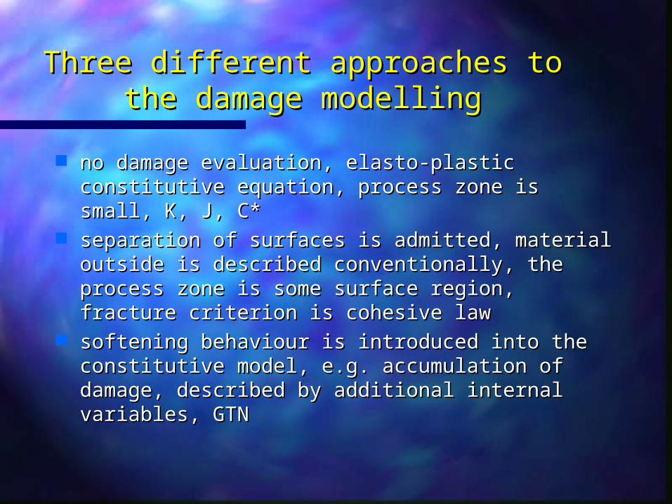
Three different approaches to the Three different approaches to the damage modellingdamage modelling
no damage evaluation, elasto-plastic no damage evaluation, elasto-plastic constitutive equation, process zone is small, K, constitutive equation, process zone is small, K, J, C*J, C*
separation of surfaces is admitted, material separation of surfaces is admitted, material outside is described conventionally, the outside is described conventionally, the process zone is some surface region, fracture process zone is some surface region, fracture criterion is cohesive lawcriterion is cohesive law
softening behaviour is introduced into the softening behaviour is introduced into the constitutive model, e.g. accumulation of constitutive model, e.g. accumulation of damage, described by additional internal damage, described by additional internal variables, GTNvariables, GTN

Plastic zone ahead the crack Plastic zone ahead the crack tiptip
conditioncondition SSYSSY
conditionconditionelasto-plasticelasto-plastic
conditionconditionLSYLSY
regionregion::
large deformationlarge deformationJ-J-integralintegral conception conception K faktor K faktor conception conceptionnon defined only by non defined only by one parameterone parameter

2. 2. Local approach - BereminLocal approach - Beremin
· Beremin· Beremin model model 1. averaging stresses over 1. averaging stresses over
FPZFPZ 2. probability of fracture2. probability of fracture
· Extension to Fracture · Extension to Fracture MechanicsMechanics
1. direct toughness 1. direct toughness prediction for SSYprediction for SSY
2. TSM2. TSM, , MinamiMinami, , KoppenhoeferKoppenhoefer, , RuggieriRuggieri
m
ii
miW VV 01 /
muWfP /exp1
mu
mICmy
f V
BCK
P
0
44
1
1ln

Local parameters technique determination
.)}/({ /101 m
im
W VV
1600 1700 1800 1900 2000 w [M Pa ]
0.0
0.2
0.4
0 .6
0.8
1.0C
umul
ativ
e pr
obab
ility
= 4 00 m
C -M n cast s teel
= 2 00 m = 1 00 m
-0.2 -0.16 -0.12 -0.08 -0.04 0
contraction [mm]
0
10
20
30
40
50
load
[kN
]

0 0.04 0.08 0.12 0.16 0.2JC [M P am ] s ize and constra in t corrected
0
0.04
0.08
0.12
0.16
0.2J C
[MP
am]
size
cor
rect
ed
w correction
m
u
wJ)()(

3. 3. Gurson-Tvergaard modelGurson-Tvergaard model (GT)(GT) nucleationnucleation
ff00 = 0,005 = 0,005
ffCC = 0,035 = 0,035
qq11 = 1,5 = 1,5; ; qq22 = 1 = 1
D D == 0,2 mm 0,2 mm
ffNN = 0,004 = 0,004
NN = 0,3 = 0,3
SSNN = 0,1 = 0,1
HMHHMHplasticityplasticity
GTGTplast.plast.
ff00
ffCC
DD

012
3cosh2
3
2 2*3
2*12
fq
qfq
SS
YS
m
YS
ijij
2
2
1exp
2 N
Np
N
N
SS
fA
GT x GTN GT x GTN modelmodel
ccF
cuc ff
ff
fff
f
f
ff
ff
c
c
q1, q2, q3 are used to adjust the modelq1, q2, q3 are used to adjust the model mm is hydrostatic stress is hydrostatic stress
YSYS is yield stress is yield stress
f* is void fraction, ff* is void fraction, fc c is the critical void fraction for is the critical void fraction for
coalescencecoalescence ffF F is the final value of f, fis the final value of f, fuu*=1/q1.*=1/q1.
f *
fu *
fc
fc fF f
GTGTN
dfdfnucl.nucl.=Ad=Adpp

material parameters identificationmaterial parameters identification
500 m
f1=0.0073 f2=0.0073 f3=0.0083 f4=0.0126 f5=0.0131 f6=0.0349
void distribution in the neck area void distribution in the neck area of the round tensile barof the round tensile bar
void distribution in non-affected void distribution in non-affected areaarea

the influence of the mesh size on the curve the influence of the mesh size on the curve elongation-contractionelongation-contraction
0
2
4
6
8
L
[m
m]
0 0.5 1 1.5 2 2.5
d [m m ]
f0 = fN = 0
f0 = 0,001
f0 = 0,0001
fN = 0 ,04G T m odel
num ber of e lem ents: 10
0
2
4
6
8
L
[m
m]
0 0.5 1 1.5 2 2.5
d [m m ]
f0 = fN = 0
f0 = 0,001
f0 = 0,0001
fN = 0,04G T m odel
num ber of e lem ents: 14

varying values of fvarying values of f00 and f and fN N and determination of input dataand determination of input data
0 1 2 3
d [m m ]
0
2
4
6
8
10
L
[mm
]
EXPf0=fN =0
fN=0.004
fN=0.04
fN=0.06
f0 = 0.005
G T m odel
0 1 2 3
d [m m ]
0
2
4
6
8
10
L
[mm
]EXPf0=fN =0
f0=0.005
f0=0.001
f0=0.008
fN = 0.004
G T m odel
ff00 = 0.005, f = 0.005, fFF (f (fCC) = 0.035) = 0.035 q1 = 1.5, q2 = 1 (q3 = q1 q1 = 1.5, q2 = 1 (q3 = q122))
ffNN = 0.004 = 0.004 NN = 0.3, S = 0.3, SN N = 0.1= 0.1

3PB SE(B)3PB SE(B)
L/2
W
a
B/2
L = 250 mmL = 250 mm l = 200 mml = 200 mmW = 50 mmW = 50 mm B = 25 mmB = 25 mm a = 25,25 mma = 25,25 mm

mesh sizemesh size
0 1 2 3 40.5 1.5 2.5 3.5
C O D [m m ]
0
20
40
60
5
10
15
25
30
35
45
50
55
65
F [k
N]
EXPM KP (0 .1)M KP (0 .05)
2.5
mm D/2

0 0.5 1 1.5 2 2.5
a [m m ]
0
200
400
600
800
J [M
Pam
m]
EXPq 2=0.8
q 2=0.82 M KP
q 2=0.85
"construction line"ASTM 1820:J = 2Ya
J
J0.2BL
JI SZW
J0.2
JI
a0.2 mmaSZW
FEM J=1,39FEM J=1,39yyaa

The influence ofThe influence of q q22 on the values on the values
ofof J-integrálu J-integrálu at stable crack at stable crack initiationinitiation
The influence of the h parameter The influence of the h parameter (triaxiality parameter)(triaxiality parameter)
0.75 0.8 0.85 0.9 0.95 1q 2 [-]
40
60
80
100
120J i F
EM
[M
Pam
m]
0.9 1 1.1 1.20.95 1.05 1.15
h [-]
40
60
80
100
120
J i FE
M [M
Pam
m]

4. Cohesive-zone modelling4. Cohesive-zone modelling

ductileductile

crack pathcrack path

5. Summary5. Summary
The coincidence of the results of the numerical modelling and the The coincidence of the results of the numerical modelling and the experiment is generally the basic criterion.experiment is generally the basic criterion.