Socket example1 Berkeley Sockets Details for everyday use Carsten Griwodz.
FEM-Training
(C) 2019 byIng.Büro HTA-Software
www.femcad.dewww.fem-infos.com
FEM-Training 1
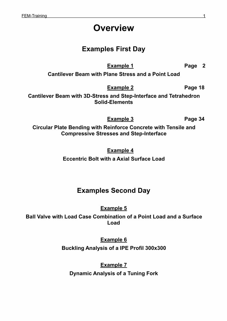
Overview
Examples First Day
Example 1 Page 2Cantilever Beam with Plane Stress and a Point Load
Example 2 Page 18Cantilever Beam with 3D-Stress and Step-Interface and Tetrahedron
Solid-Elements
Example 3 Page 34Circular Plate Bending with Reinforce Concrete with Tensile and
Compressive Stresses and Step-Interface
Example 4Eccentric Bolt with a Axial Surface Load
Examples Second Day
Example 5Ball Valve with Load Case Combination of a Point Load and a Surface
Load
Example 6Buckling Analysis of a IPE Profil 300x300
Example 7Dynamic Analysis of a Tuning Fork

FEM-Training 2
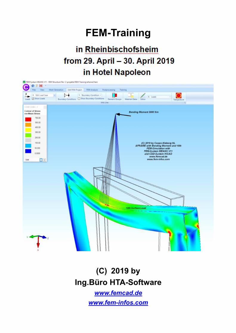
FEM-Training withFEM-SystemMEANS V11
Example 1Cantilever Beam with
2D-Plane-Stress-Analysis
(C)w2019 byIng.Büro HTA-Software
www.femcad.dewww.fem-infos.com
FEM-Training 3
Example 1:
Cantilever Beam with 2D-Plane-Stress-Analysis
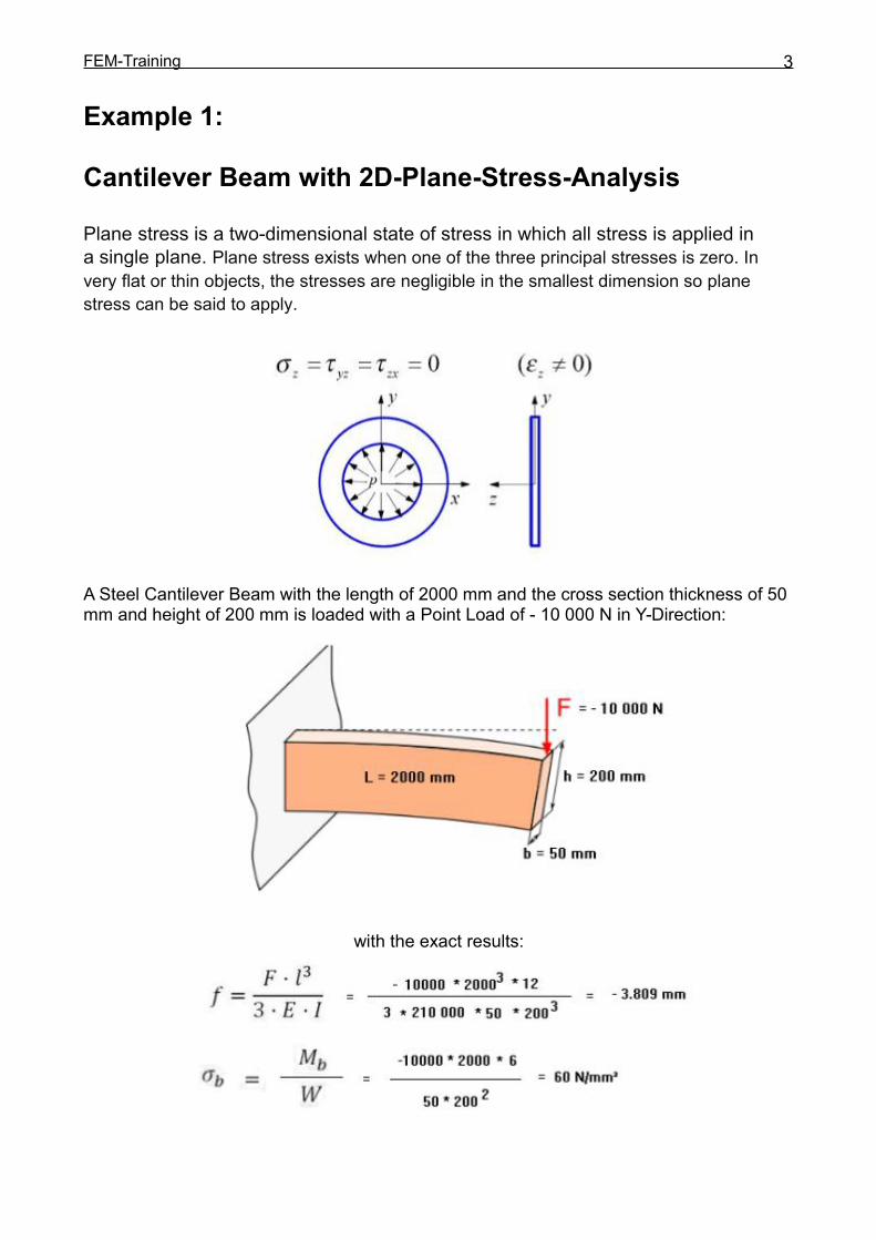
Plane stress is a two-dimensional state of stress in which all stress is applied ina single plane. Plane stress exists when one of the three principal stresses is zero. Invery flat or thin objects, the stresses are negligible in the smallest dimension so planestress can be said to apply.
A Steel Cantilever Beam with the length of 2000 mm and the cross section thickness of 50mm and height of 200 mm is loaded with a Point Load of - 10 000 N in Y-Direction:
with the exact results:

FEM-Training 4
Create the Line Model
Start MEANS V11 via the Windows desktop icon and select the tab "File" andmenu "New" and click on the project menu "Create a new Model with Beam-Line-Modus"The dialog box for the line mode appears on the right side.
In the Line-Modus here you will find menus containing Nodes, Rectangles or Circles canbe created and connected.
FEM-Training 5
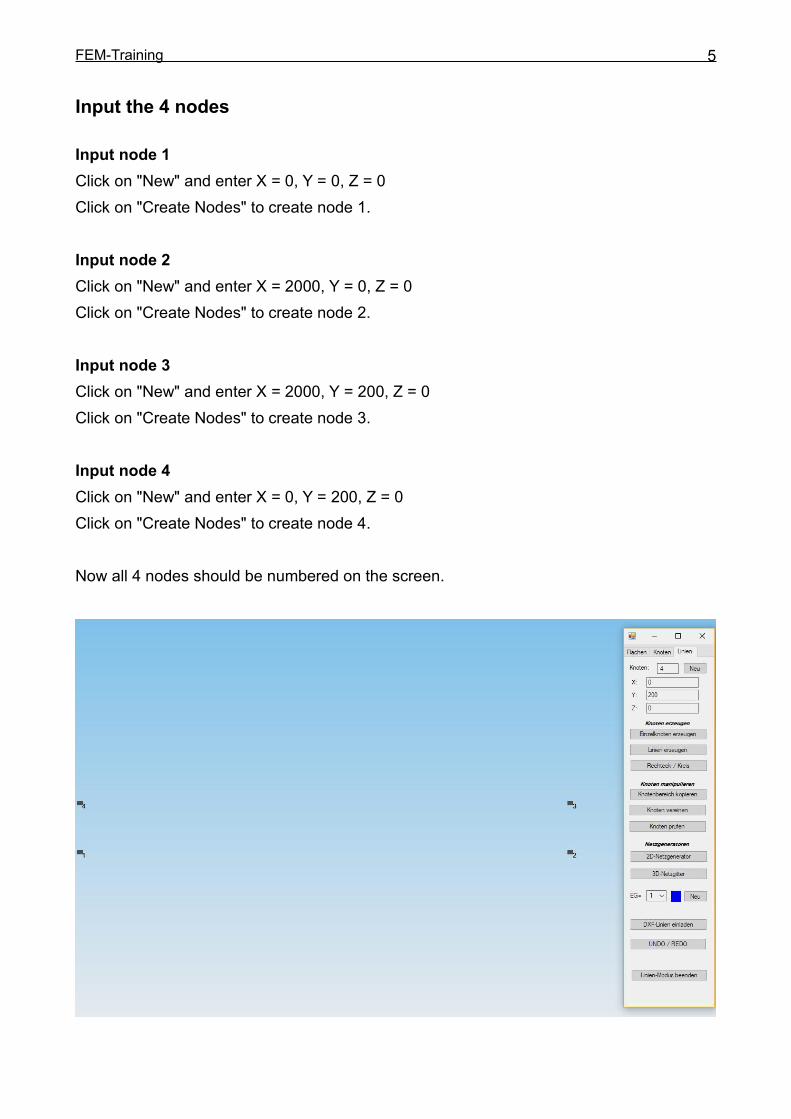
Input the 4 nodes
Input node 1Click on "New" and enter X = 0, Y = 0, Z = 0Click on "Create Nodes" to create node 1.
Input node 2Click on "New" and enter X = 2000, Y = 0, Z = 0Click on "Create Nodes" to create node 2.
Input node 3Click on "New" and enter X = 2000, Y = 200, Z = 0Click on "Create Nodes" to create node 3.
Input node 4Click on "New" and enter X = 0, Y = 200, Z = 0Click on "Create Nodes" to create node 4.
Now all 4 nodes should be numbered on the screen.
FEM-Training 6
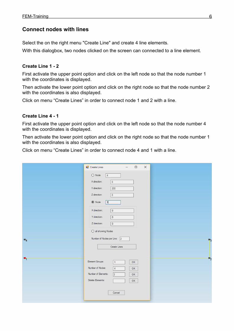
Connect nodes with lines
Select the on the right menu "Create Line" and create 4 line elements.With this dialogbox, two nodes clicked on the screen can connected to a line element.
Create Line 1 - 2First activate the upper point option and click on the left node so that the node number 1with the coordinates is displayed.Then activate the lower point option and click on the right node so that the node number 2with the coordinates is also displayed.Click on menu “Create Lines” in order to connect node 1 and 2 with a line.
Create Line 4 - 1First activate the upper point option and click on the left node so that the node number 4with the coordinates is displayed.Then activate the lower point option and click on the right node so that the node number 1with the coordinates is also displayed.Click on menu “Create Lines” in order to connect node 4 and 1 with a line.

FEM-Training 7
Mesh GenerationSelect the right side menu "2D Mesh Generator" and set a mesh density = 150 and selectthe menu "MESH GENERATION” to generate
a 2D FEM triangle mesh consisting of 1546 TRI3S plane elements and 870 nodes.

FEM-Training 8
Create Boundary ConditionsThe cantilever beam is fixed clamped at the left end. Create the BCs in the following steps:Select the "Edit FEM Project" tab and click on the BC icon to enter the boundaryconditions.In the BC dialog box, select "Clamped fixed" and the selection “Dragging a model region”and click on the button "Create BCs" to create a border (press and hold the mousebutton)around the left end. Now all selected nodes are displayed in the Selectbox, there youselect "Create" to create the RBs.
FEM-Training 9
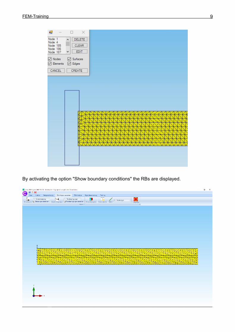
By activating the option "Show boundary conditions" the RBs are displayed.
FEM-Training 10
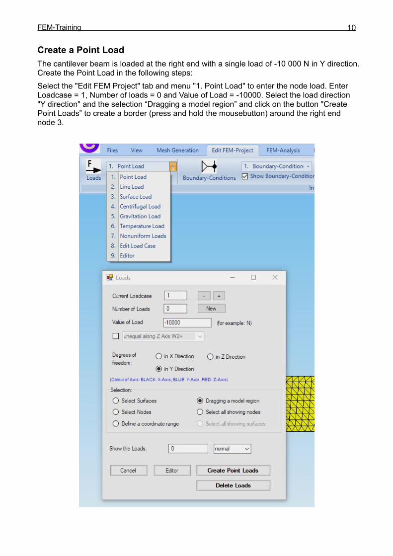
Create a Point LoadThe cantilever beam is loaded at the right end with a single load of -10 000 N in Y direction.Create the Point Load in the following steps:Select the "Edit FEM Project" tab and menu "1. Point Load" to enter the node load. EnterLoadcase = 1, Number of loads = 0 and Value of Load = -10000. Select the load direction"Y direction" and the selection “Dragging a model region” and click on the button "CreatePoint Loads” to create a border (press and hold the mousebutton) around the right endnode 3.

FEM-Training 11
Now the selected node 3 are displayed in the Selectbox, there you select "Create" tocreate the Point Load.By activating the option "Show Loads" the Point Load are displayed.
FEM-Training 12
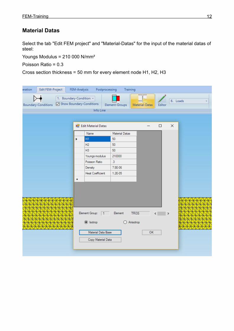
Material Datas
Select the tab "Edit FEM project" and "Material-Datas" for the input of the material datas ofsteel:Youngs Modulus = 210 000 N/mm²Poisson Ratio = 0.3Cross section thickness = 50 mm for every element node H1, H2, H3

FEM-Training 13
FEM-Analysis
Select the "FEM-Analysis" tab and menu "1. Statics" to calculate the displacements andstresses with the MEANS-Solver from Dr.Kühn or with the Quicksolver. For the Quicksolver,MEANS V11 is shut down before the FEM calculation and is automatically restarted afterthe calculation.

FEM-Training 14
MEANS-Solver from Dr.Kühn
Quick-Solver for larger calculations:

FEM-Training 15
Postprocessing
Select the „Postprocessing” tab and click on the Icon to display the displacementsand stresses contours.
Set the following:
Contour of Displacements Load Case 1 Edit Accuracy = 4 Displacement in y direction and choose “Start Postprocessing”
FEM-Training 16
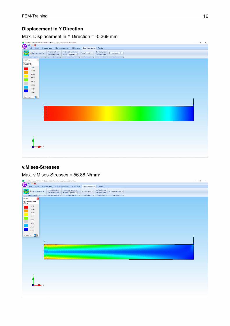
Displacement in Y DirectionMax. Displacement in Y Direction = -0.369 mm
v.Mises-StressesMax. v.Mises-Stresses = 56.88 N/mm²
FEM-Training 17
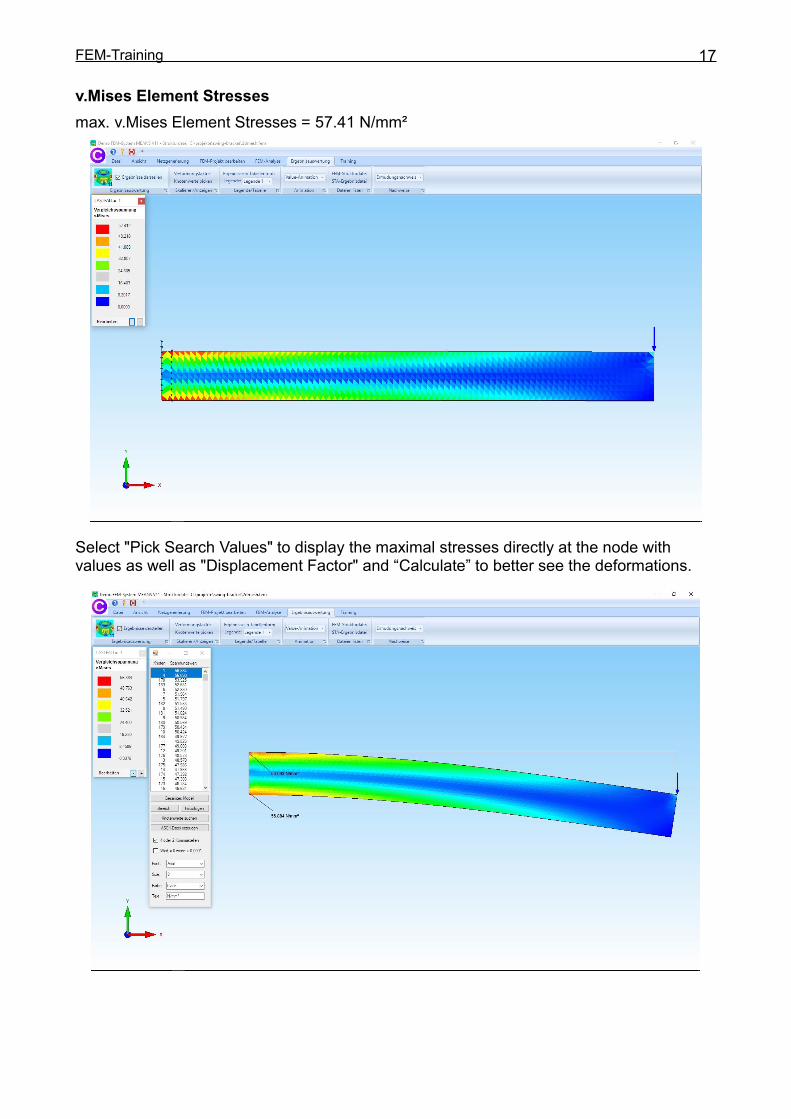
v.Mises Element Stressesmax. v.Mises Element Stresses = 57.41 N/mm²
Select "Pick Search Values" to display the maximal stresses directly at the node withvalues as well as "Displacement Factor" and “Calculate” to better see the deformations.

FEM-Training 18
FEM-Training withFEM-SystemMEANS V11
Example 2Cantilever Beam with 3D-Stress-Analysis
and STEP-Interface
(C) 2019 byIng.Büro HTA-Software
www.femcad.dewww.fem-infos.com

FEM-Training 19
Example 2:
Cantilever Beam with 3D-Stress-Analysis and STEP-Interface
A Steel Cantilever Beam with the length of 2000 mm and the cross section thickness of 50mm and height of 200 mm is loaded with a Point Load of - 10 000 N in Y-Direction:
with the exact results:
Calculation with TET4 and TET10
MEANS contains isoparametric tetrahedron, pentahedron and hexahedron solid elementsfor the 3D-Stress-Analysis. The linear TET4 and quadratic TET10 element types are by farthe most common forms of unstructured mesh generation.
FEM-Training 20
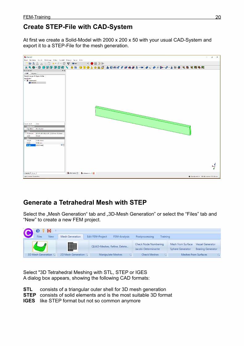
Create STEP-File with CAD-System
At first we create a Solid-Model with 2000 x 200 x 50 with your usual CAD-System andexport it to a STEP-File for the mesh generation.
Generate a Tetrahedral Mesh with STEPSelect the „Mesh Generation“ tab and „3D-Mesh Generation” or select the “Files” tab and“New” to create a new FEM project.
Select "3D Tetrahedral Meshing with STL, STEP or IGESA dialog box appears, showing the following CAD formats:
STL consists of a triangular outer shell for 3D mesh generationSTEP consists of solid elements and is the most suitable 3D formatIGES like STEP format but not so common anymore
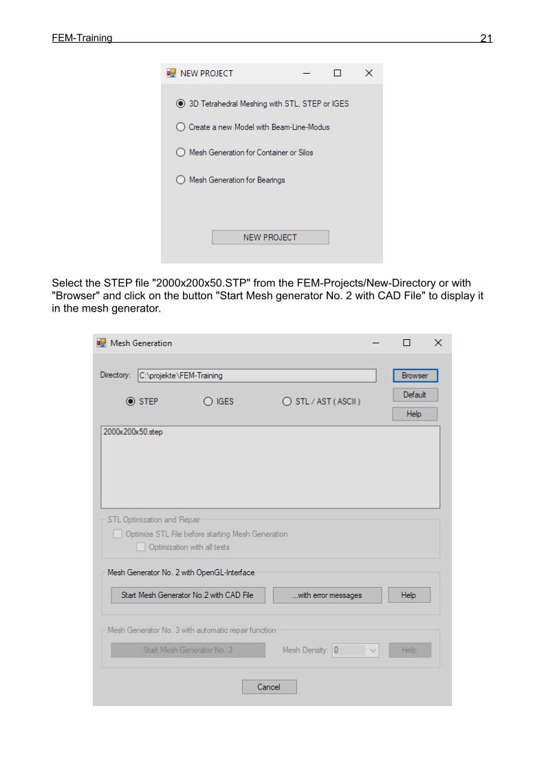
FEM-Training 21
Select the STEP file "2000x200x50.STP" from the FEM-Projects/New-Directory or with"Browser" and click on the button "Start Mesh generator No. 2 with CAD File" to display itin the mesh generator.

FEM-Training 22
The STEP File can be seen in the mesh generator and can be rotated as required.
Select the menu "Mesh" and "Meshing Options" and generate with the mesh density"moderate" and the menu "Generate Mesh" a FEM Model with tetrahedral elements.

FEM-Training 23
Select “Refinement” and “Refine uniform” to refine 2x the moderate mesh. The FEM Meshnow consists of 16448 tetrahedral elements and 3875 nodes.
After Generation, the FEM Mesh named "test.fem" must be exported to MEANS V11.Select the "File" and "Export Mesh" menu and save the mesh "test.fem" into the defaultDebug / Mesh directory.
FEM-Training 24
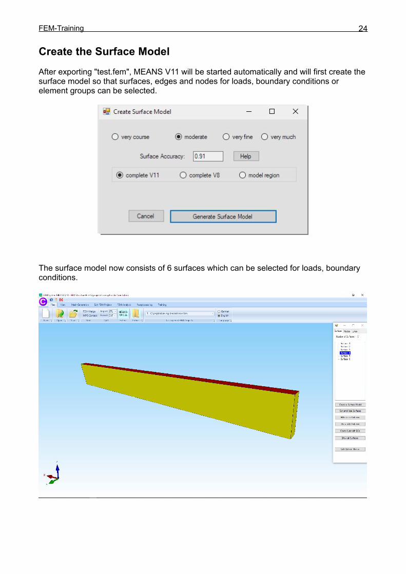
Create the Surface ModelAfter exporting "test.fem", MEANS V11 will be started automatically and will first create thesurface model so that surfaces, edges and nodes for loads, boundary conditions orelement groups can be selected.
The surface model now consists of 6 surfaces which can be selected for loads, boundaryconditions.
FEM-Training 25
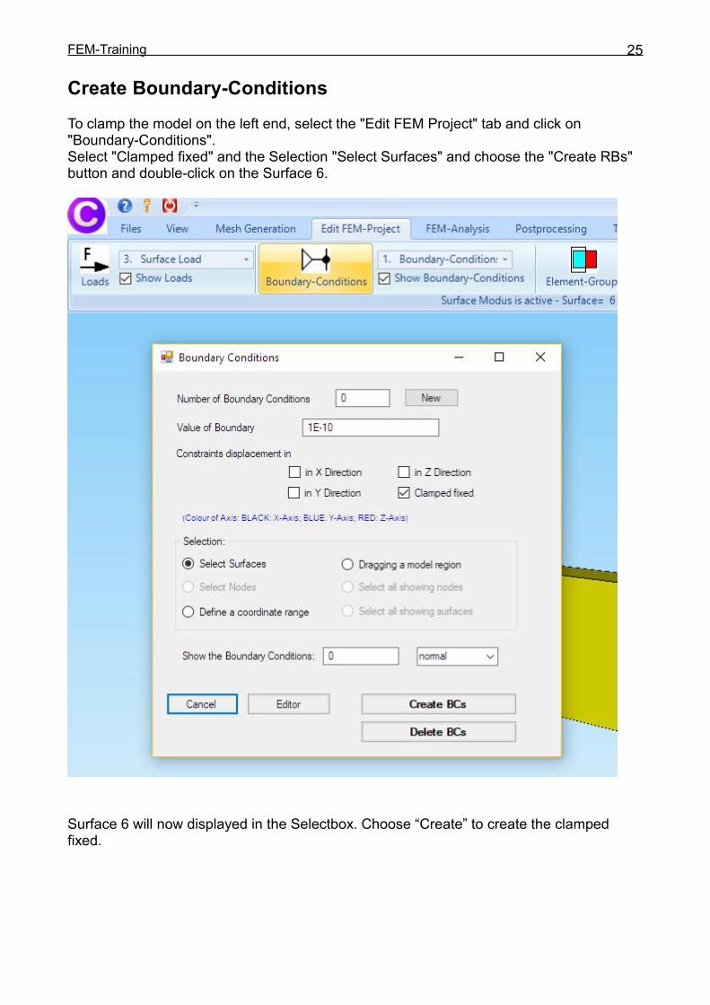
Create Boundary-ConditionsTo clamp the model on the left end, select the "Edit FEM Project" tab and click on"Boundary-Conditions".Select "Clamped fixed" and the Selection "Select Surfaces" and choose the "Create RBs"button and double-click on the Surface 6.
Surface 6 will now displayed in the Selectbox. Choose “Create” to create the clampedfixed.
FEM-Training 26
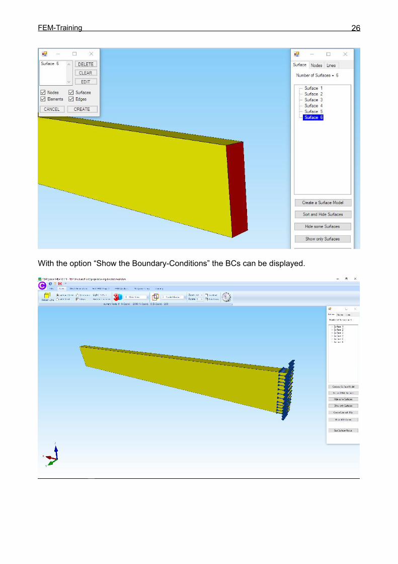
With the option “Show the Boundary-Conditions” the BCs can be displayed.

FEM-Training 27
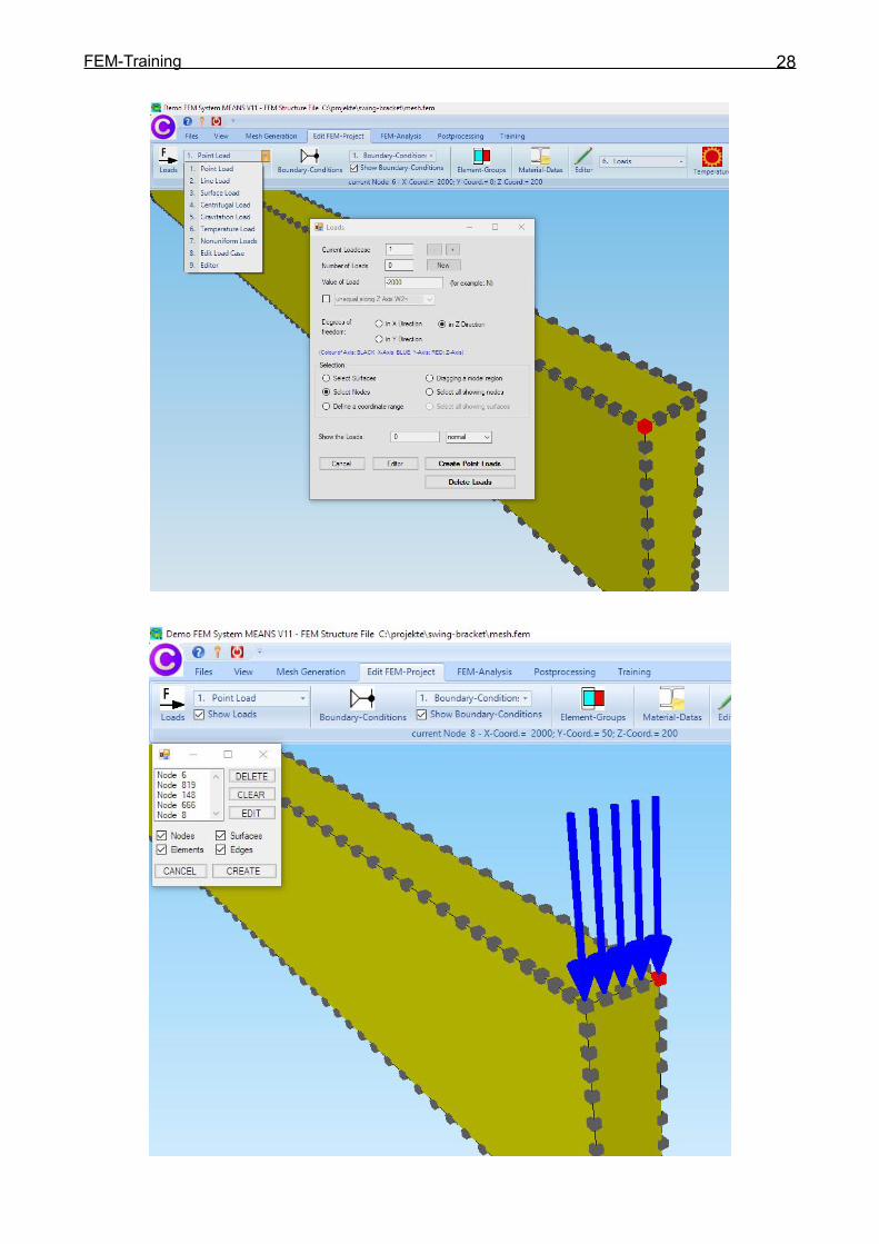
Create a Point LoadThe cantilever beam is loaded at the right end with a single load of -10 000 N in Z direction.Create the Point Load in the following steps:
Show Edge Nodes
Now rotate the model with the right mouse button to the following view so that the right endis in front. Select the "View" tab and click on "2. Node-Modus" and choose in the nextdialogbox menu “Show Nodes” to display the nodes on the edges.
Select the "Edit FEM Project" tab and menu "1. Point Load" to enter the node load. Enter
Loadcase = 1 Number of Loads = 0 Value of Loads = -2000 N Direction = in Z-Direction Selection = Select Nodes
And choose the Button “Create Point Loads” and click on the five edge nodes 6, 819, 144,666 and 8. This selected nodes are displayed in the Selectbox, choose “Create” to createthe 5 Point Loads with a value of 2000 N.
FEM-Training 28
FEM-Training 29
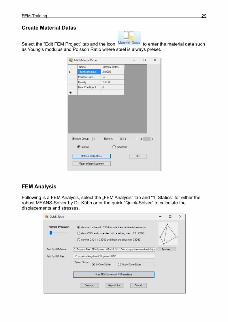
Create Material Datas
Select the "Edit FEM Project" tab and the icon to enter the material data suchas Young's modulus and Poisson Ratio where steel is always preset.
FEM Analysis
Following is a FEM Analysis, select the „FEM Analysis“ tab and "1. Statics" for either therobust MEANS-Solver by Dr. Kühn or or the quick "Quick-Solver" to calculate thedisplacements and stresses.
FEM-Training 30
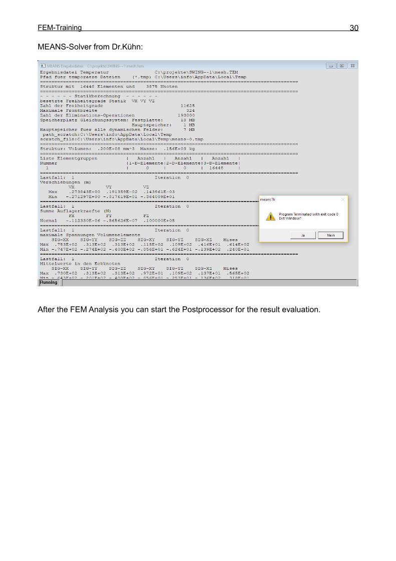
MEANS-Solver from Dr.Kühn:
After the FEM Analysis you can start the Postprocessor for the result evaluation.
FEM-Training 31
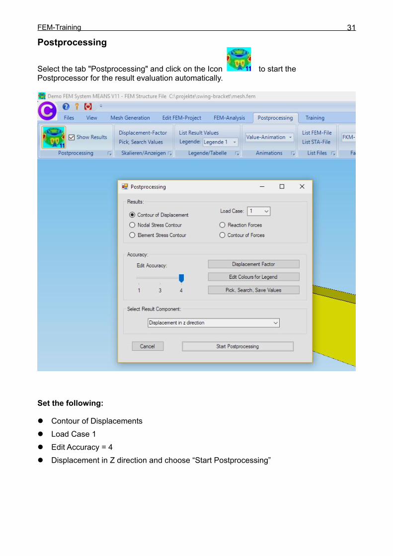
Postprocessing
Select the tab "Postprocessing" and click on the Icon to start thePostprocessor for the result evaluation automatically.
Set the following:
Contour of Displacements Load Case 1 Edit Accuracy = 4 Displacement in Z direction and choose “Start Postprocessing”

FEM-Training 32
max. Displacements in Z Direction = -3.64 mm
max. v.Mises Nodal Stresses = 56 MPa

FEM-Training 33
max. v.Mises Element Stresses = 61 MPa
Select "Pick Search Values" to display the maximal stresses directly at the node withvalues as well as "Displacement Factor" and “Calculate” to better see the deformations.
FEM-Training 34
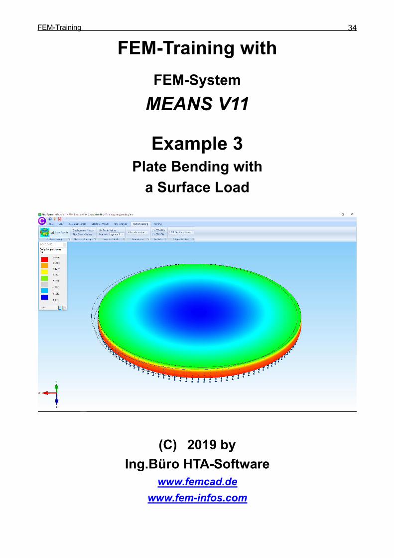
FEM-Training withFEM-SystemMEANS V11
Example 3Plate Bending witha Surface Load
(C)w2019 byIng.Büro HTA-Software
www.femcad.dewww.fem-infos.com

FEM-Training 35
Example 3:Circular Plate with BendingA plate is a planer structure with a very small thickness in comparison to the planerdimensions. The forces applied on a plate are vertical to the plane of the plate. In contrastto the plane elements with a cross force to the plane. The sum of planes and plates arethe shell elements.
The plate is made of Reinforced Concrete with an Young Modulus of 30,000 MPa and aCompressive Strength of 28 MPa and a very much lower Tensile Strength of only 2.2 MPa

FEM-Training 36
Exact Calculation
A circular plate loaded with bending can be exactly calculated with a usual differentialequation, since only the radius R is required as the only independent variable.
Calculation of the maximal Bending Moment M max in the Midside
M max = M x = M y = ( 3 + P * R2 / 16
- 10 kN / m² * 25 m² * 3.2= 16 = 50 kN m
Calculation of the maximal Bending Stress max in the Midside
max = 6 * Mmax / H ² = 6 * 50 kN m / 0.16 m² = 1 875 kN / m²
= 1 875 000 N / m² = 1.875 N/mm² = 1.875 MPa
Calculation of the maximal Displacement w in the Midside
w = 2.54 mm
FEM-Training 37
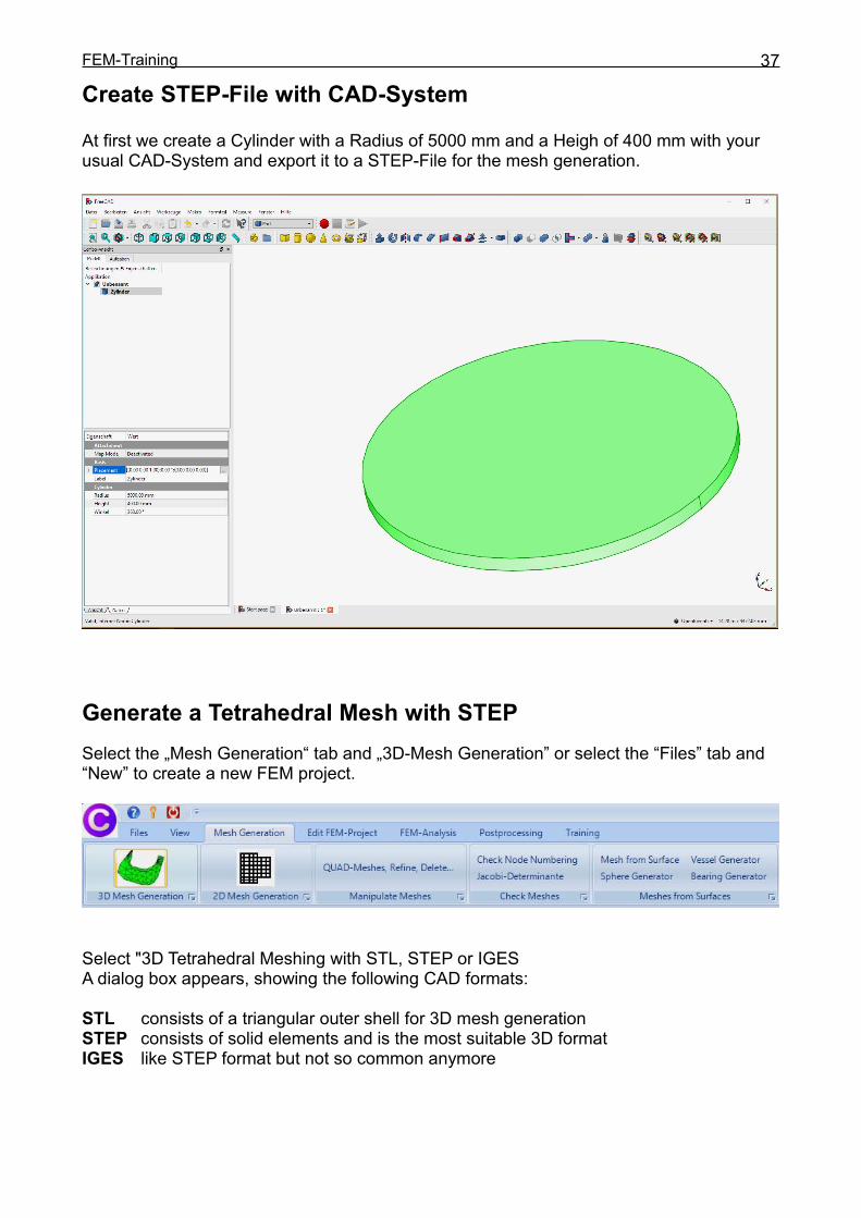
Create STEP-File with CAD-System
At first we create a Cylinder with a Radius of 5000 mm and a Heigh of 400 mm with yourusual CAD-System and export it to a STEP-File for the mesh generation.
Generate a Tetrahedral Mesh with STEPSelect the „Mesh Generation“ tab and „3D-Mesh Generation” or select the “Files” tab and“New” to create a new FEM project.
Select "3D Tetrahedral Meshing with STL, STEP or IGESA dialog box appears, showing the following CAD formats:
STL consists of a triangular outer shell for 3D mesh generationSTEP consists of solid elements and is the most suitable 3D formatIGES like STEP format but not so common anymore

FEM-Training 38
Select the STEP file "Plate_Bending.STEP" from the FEM-Projects “FEM-Training” or with"Browser" and click on the button "Start Mesh generator No. 2 with CAD File" to display itin the mesh generator.
The STEP File can be seen in the mesh generator and can be rotated as required.

FEM-Training 39
Select the menu "Mesh" and "Meshing Options" and generate with the mesh density"moderate" and the menu "Generate Mesh" a FEM Model with tetrahedral elements.
FEM-Training 40
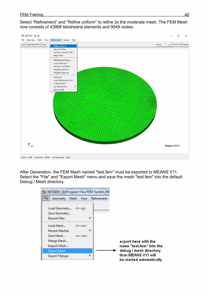
Select “Refinement” and “Refine uniform” to refine 2x the moderate mesh. The FEM Meshnow consists of 43968 tetrahedral elements and 9549 nodes.
After Generation, the FEM Mesh named "test.fem" must be exported to MEANS V11.Select the "File" and "Export Mesh" menu and save the mesh "test.fem" into the defaultDebug / Mesh directory.
FEM-Training 41
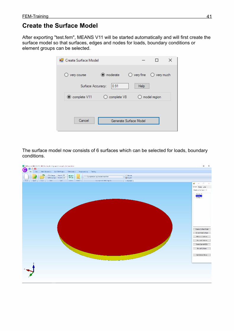
Create the Surface ModelAfter exporting "test.fem", MEANS V11 will be started automatically and will first create thesurface model so that surfaces, edges and nodes for loads, boundary conditions orelement groups can be selected.
The surface model now consists of 6 surfaces which can be selected for loads, boundaryconditions.

FEM-Training 42
Create Boundary-ConditionsThe Displacements of the Circular Plate are constrained on the outside diameter in Zdirection. Select the "Edit FEM Project" tab and click on "Boundary-Conditions".Select "in Z Direction” and "Select Surfaces" and choose the button "Create RBs" and clickon the Surface 3.
Surface 3 will now displayed in the Selectbox. Choose “Create” to create the BCs.
With the option “Show the Boundary-Conditions” the BCs can be displayed.
FEM-Training 43
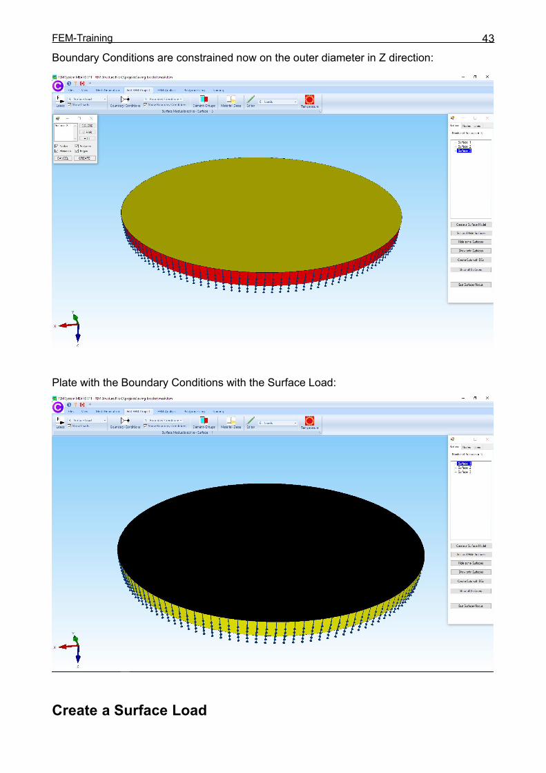
Boundary Conditions are constrained now on the outer diameter in Z direction:
Plate with the Boundary Conditions with the Surface Load:
Create a Surface Load
FEM-Training 44
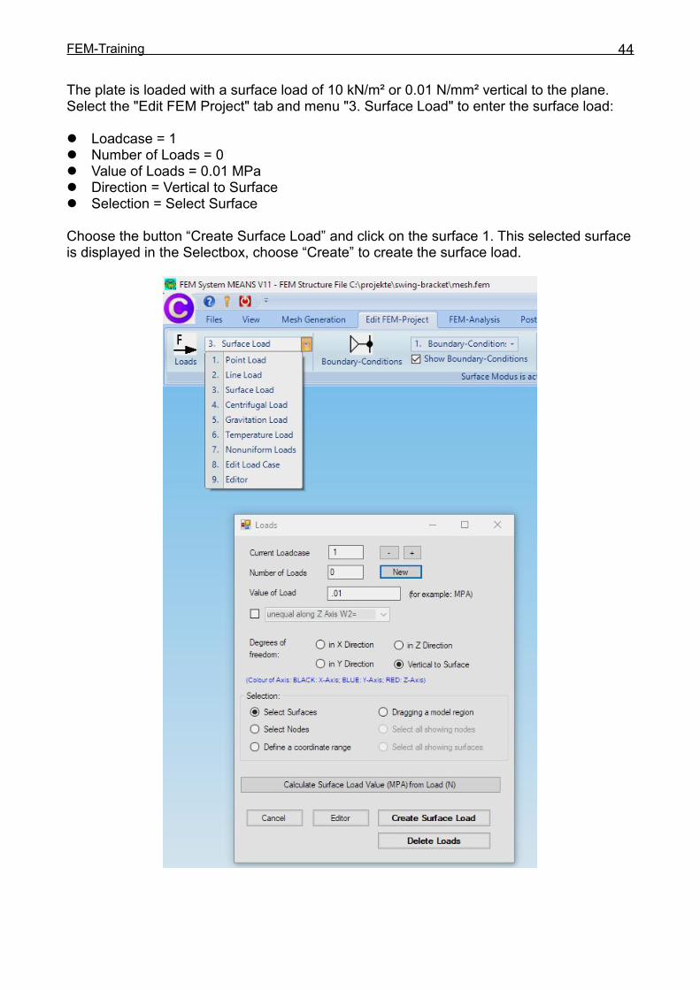
The plate is loaded with a surface load of 10 kN/m² or 0.01 N/mm² vertical to the plane.Select the "Edit FEM Project" tab and menu "3. Surface Load" to enter the surface load:
Loadcase = 1 Number of Loads = 0 Value of Loads = 0.01 MPa Direction = Vertical to Surface Selection = Select Surface
Choose the button “Create Surface Load” and click on the surface 1. This selected surfaceis displayed in the Selectbox, choose “Create” to create the surface load.

FEM-Training 45
Create Material Datas
Select the "Edit FEM Project" tab and the icon to enter the material data forReinforced Concrete with a Young's Modulus = 30 000 N/mm² and Poisson Ratio = 0.2.
FEM AnalysisFollowing is a FEM Analysis, select the „FEM Analysis“ tab and "1. Statics" for either therobust MEANS-Solver by Dr. Kühn or or the quick "Quick-Solver" to calculate thedisplacements and stresses.

FEM-Training 46
Postprocessing
Select the tab "Postprocessing" and click on the Icon to start thePostprocessor for the result evaluation automatically.
Set the following:
Contour of Displacements Load Case 1 Edit Accuracy = 4 Displacement in Z direction and choose “Start Postprocessing”
Select "Pick Search Values" to display the maximal stresses directly at the node withvalues as well as "Displacement Factor" and “Calculate” to better see the deformations.
FEM-Training 47
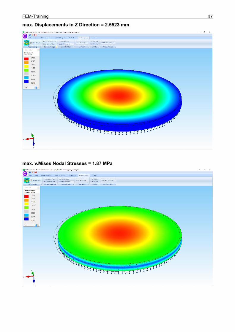
max. Displacements in Z Direction = 2.5523 mm
max. v.Mises Nodal Stresses = 1.87 MPa
FEM-Training 48
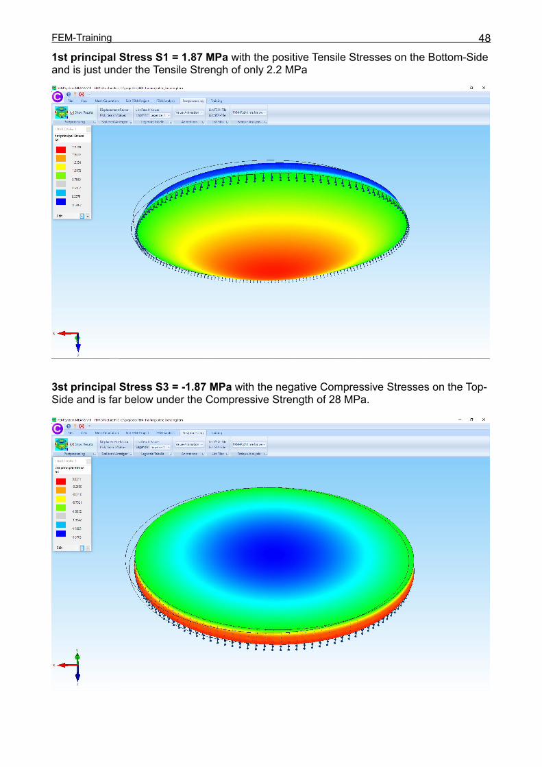
1st principal Stress S1 = 1.87 MPa with the positive Tensile Stresses on the Bottom-Sideand is just under the Tensile Strengh of only 2.2 MPa
3st principal Stress S3 = -1.87 MPa with the negative Compressive Stresses on the Top-Side and is far below under the Compressive Strength of 28 MPa.