OMS 2400 Family - svpro.ru ProductDescription.pdf · OMS 2400 Family, Optical Ethernet ... Some...
66
Ericssonwide Internal TECHN PRODUCT DESCR Prepared (also subject responsible if other) No. ETL/G/S Peter Barwick 221 02-ZAP 701 27/1 Approved Checked Date Rev Reference ETL/G/S Karl-Eric K Malberg 26/05/2006 B OMS 2400 Family Product Description
Transcript of OMS 2400 Family - svpro.ru ProductDescription.pdf · OMS 2400 Family, Optical Ethernet ... Some...

Ericssonwide Internal TECHN PRODUCT DESCR
Prepared (also subject responsible if other) No.
ETL/G/S Peter Barwick 221 02-ZAP 701 27/1 Approved Checked Date Rev Reference
ETL/G/S Karl-Eric K Malberg 26/05/2006 B
OMS 2400 Family
Product Description

Ericssonwide Internal TECHN PRODUCT DESCR
Prepared (also subject responsible if other) No.
ETL/G/S Peter Barwick 221 02-ZAP 701 27/1 Approved Checked Date Rev Reference
ETL/G/S Karl-Eric K Malberg 26/05/2006 B
Since January 2006 Marconi is a member of the Ericsson group. OMS 2400 Family, Optical Ethernet Platform is part of the Ericsson Optical Multi-Service portfolio. Copyright © Ericsson AB, Ericsson Limited, Marconi SpA and Ericsson GmbH 2006, – All Rights Reserved Disclaimer No part of this document may be reproduced in any form without the written permission of the copyright owner. The information in this work is the property of Ericsson AB, Ericsson Limited, Marconi SpA and Ericsson GmbH. Except as specifically authorized in writing by Ericsson AB, Ericsson Limited, Marconi SpA and Ericsson GmbH the receiver of this work shall keep the information contained herein confidential and shall protect the same in whole or in part from disclosure and dissemination to third parties. Disclosure and disseminations to the receiver's employees shall only be made on a strict need to know basis. The content of this document are subject to revision without notice due to continued progress in methodology, design and manufacturing. Ericsson AB, Ericsson Limited, Marconi SpA and Ericsson GmbH shall have no liability or responsibility for factual inaccuracies or typographical errors for any error or damage of any kind resulting from the use of this document. Occurrence of blank pages is intentional to accommodate double-sided printing.

OMS2400 Family Optical Ethernet Platform
Product Description

Product Description OMS2400 Family - Optical Ethernet Platform
Page 2 of 64 Copyright – Refer to Page 2 Issue 2
Document code: Date of issue: Issue: Comments:
4on-pd000086-e-A 24–02–2006 2

OMS2400 – Optical Ethernet Platform Product Description
Issue 2 Copyright – Refer to Page 2 Page 3 of 64
This is an unpublished work, the copyright in which vests in Marconi Communications Limited, Marconi Communications SpA and Marconi Communications GmbH. All rights reserved. The work contains information confidential to the above companies and allsuch information is supplied without liability for errors or omissions. No part may be reproduced, disclosed or used except as authorized by contract or other written permission. The copyright and the foregoing restriction on reproduction extend to all media inwhich the information may be embodied. The above companies have used all reasonable endeavors to ensure that the information contained in this work is accurate at itsdate of issue, but reserves the right to make changes, in good faith, to such information from time to time, whether by way ofcorrection or meet market requirements or otherwise.
Marconi Communications SpA Via Negrone, 1/A 16153 Genova Italy. Telephone: +39–010–60021 Fax: +39–010–6501897
Marconi Communications Ltd. New Century Park, PO Box 53, Coventry CV3 1HJ, England Telephone: +44 (0)24 7656 2000 Fax:+44 (0)24 7656 7000 Telex: 31361 MARCOV
Marconi Communications GmbH Gerberstraße 33 71522 Backnang Germany Telephone: +49 (0) 71 91 13 - 0 Fax: +49 (0) 71 91 13 - 32 12

Product Description OMS2400 Family - Optical Ethernet Platform
Page 4 of 64 Copyright – Refer to Page 2 Issue 2
Table of Contents
1 Introduction ..............................................................................................................12
1.1 Overview ..................................................................................................................12 1.2 Features and Benefits of the OMS2400 Family........................................................13 1.3 Main Features of OMS2410 (Single card size).........................................................14 1.4 Main Features of OMS2430 (Compact size) ............................................................15 1.5 Main Features of OMS2450 (Medium size)..............................................................15 1.6 Main Features of OMS2470 (Large size) .................................................................15 1.7 Traffic Types.............................................................................................................15
2 System concept .......................................................................................................17
3 Network positioning..................................................................................................19
3.1 General network level...............................................................................................19 3.2 Trunk-side Network Scenarios .................................................................................19 3.3 Client-side Network Scenarios .................................................................................20 3.4 Photonic Inter-working..............................................................................................21
4 Network Applications and Services..........................................................................24
4.1 Layer 2 Virtual Private Networks over MPLS ...........................................................25 4.2 Provider Bridge solution ...........................................................................................27 4.3 Q-in-Q support..........................................................................................................29
5 Product Overview.....................................................................................................31
5.1 System Design and mechanical solutions................................................................31 5.1.1 OMS2410 .................................................................................................................31 5.1.1.1 OMS2410 layout..................................................................................... 32 5.1.2 OMS2430 .................................................................................................................32 5.1.2.1 OMS2430 Shelf ...................................................................................... 33 5.1.3 OMS2450 .................................................................................................................33 5.1.3.1 OMS2450 Shelf ...................................................................................... 34 5.1.4 OMS2470 .................................................................................................................35 5.1.4.1 OMS2470 Shelf ...................................................................................... 36
6 Interfaces .................................................................................................................38
6.1 Data Traffic Units......................................................................................................38 6.2 SDH Traffic Units......................................................................................................38 6.3 System Units ............................................................................................................39 6.3.1 Packet Switching Unit (OMS2430, OMS2450 and OMS2470).................................39 6.3.2 Fabric-less Packet Switching capability (OMS2430) ................................................41 6.3.3 Fabric-less Packet Switching capability (OMS2410) ................................................44 6.3.4 Communication and Controller Unit .........................................................................44 6.4 External System Interfaces ......................................................................................45

OMS2400 – Optical Ethernet Platform Product Description
Issue 2 Copyright – Refer to Page 2 Page 5 of 64
6.4.1 Power Supply Interfaces ..........................................................................................45 6.4.2 Control and Communication (Management) Interface..............................................45
7 Equipment protections .............................................................................................46
8 Traffic Protection, OAM and Resilience mechanisms..............................................47
8.1 MPLS OAM and Protection Mechanisms .................................................................47 8.1.1 MPLS OAM ..............................................................................................................47 8.1.2 MPLS Protections.....................................................................................................50 8.1.2.1 1+1 Protection ........................................................................................ 50 8.1.2.2 1:1 Protection ......................................................................................... 51 8.1.3 Packet 1+1 protection switching...............................................................................51 8.2 Restoration mechanisms..........................................................................................52 8.2.1 LSP Restoration .......................................................................................................52 8.2.2 Fast Re-Route ..........................................................................................................53 8.3 Ethernet OAM and Protection Mechanisms .............................................................54 8.3.1 OAM functions..........................................................................................................55 8.4 Link Aggregation ......................................................................................................55 8.5 Spanning Tree..........................................................................................................57 8.5.1 Introduction...............................................................................................................57 8.5.2 Spanning Tree Protocol (STP) .................................................................................58 8.5.3 Rapid Spanning Tree Protocol (RSTP) ....................................................................59 8.5.4 Multiple Spanning Tree Protocol (MSTP) .................................................................59 8.6 SDH Protection Mechanisms ...................................................................................60 8.6.1 Multiplex Section Protection .....................................................................................60 8.6.2 Sub-Network Connection Protection ........................................................................60 8.7 Control Plane Resilience ..........................................................................................61
9 Management architecture ........................................................................................62
10 Technical Specifications ..........................................................................................63
10.1 Mechanical Construction ..........................................................................................63 10.2 Safety .......................................................................................................................63 10.2.1 Optical safety requirements......................................................................................63 10.3 Electrical Environment..............................................................................................63 10.4 Climatic and Mechanical Environment .....................................................................64 10.4.1 General.....................................................................................................................64 10.4.2 Storage Endurance ..................................................................................................64 10.4.3 Transport Endurance................................................................................................64 10.4.4 Environmental Endurance For Indoor Operation......................................................64

Product Description OMS2400 Family - Optical Ethernet Platform
Page 6 of 64 Copyright – Refer to Page 2 Issue 2
List of Figures Figure 1: System concept - example of traffic aggregation ........................................................ 17 Figure 2: Examples of trunk-side connections ........................................................................... 20 Figure 3: Examples of client-side connections ........................................................................... 21 Figure 4: WDM applications for OMS2400 family (trunk side) ................................................... 22 Figure 5: WDM applications for OMS2400 family (client side) ................................................... 23 Figure 6: Ethernet services and OMS2400 family...................................................................... 24 Figure 7: Reference network for residential applications (DSLAM backhaul) ............................ 25 Figure 8: Virtual Private Wire Service ........................................................................................ 26 Figure 9: Virtual Private LAN Service......................................................................................... 26 Figure 10: Hierarchical VPLS..................................................................................................... 27 Figure 11: Port types according to IEEE 802.1ad ...................................................................... 28 Figure 12: Q-in-Q CNP in Provider Bridge ................................................................................. 29 Figure 13: OMS2400 as “Tunnel Edge Bridge” .......................................................................... 30 Figure 14: OMS2410 layout ....................................................................................................... 32 Figure 15: OMS2430 shelf ......................................................................................................... 33 Figure 16: OMS2450 shelf ......................................................................................................... 35 Figure 17: OMS2470 shelf ......................................................................................................... 37 Figure 18: Schematic view of switch fabric connections ............................................................ 40 Figure 19: Some details of the switching architecture................................................................ 41 Figure 20: Fabric-less packet switching architecture ................................................................. 42 Figure 21: OMS2430 – Mesh configuration (up to 40 Gbit/s capacity)....................................... 43 Figure 22: OMS2430 –Configuration with central switch (80 Gbit/s capacity) ........................... 43 Figure 23: OMS2410 architecture .............................................................................................. 44 Figure 24: CCU architecture....................................................................................................... 45 Figure 25: CV and FFD LSP’s.................................................................................................... 48 Figure 26: FDI and BDI in case of physical failure ..................................................................... 49 Figure 27: Use of LSP at layer N+1 to monitor a segment of LSP at layer N............................. 49 Figure 28: LSP 1+1 protection ................................................................................................... 50 Figure 29: LSP 1:1 protection without extra traffic ..................................................................... 51 Figure 30: Example of LSP Restoration ..................................................................................... 53 Figure 31: Example of Fast Re-Route mechanisms................................................................... 54 Figure 32: Link Aggregation concept.......................................................................................... 56 Figure 33: Example of Spanning Tree at UNI ............................................................................ 57 Figure 34: Example of Spanning Tree at NNI ............................................................................ 58 Figure 35: Example of MSTP in a Provider Bridge network ....................................................... 60 Figure 36: Network Management System diagram .................................................................... 62 List of Tables Table 1: Number of interfaces offered by OMS2410.................................................................. 31 Table 2: Number of interfaces offered by OMS2430.................................................................. 33 Table 3: Number of interfaces offered by OMS2450.................................................................. 34

OMS2400 – Optical Ethernet Platform Product Description
Issue 2 Copyright – Refer to Page 2 Page 7 of 64
Table 4: Number of interfaces offered by OMS2470.................................................................. 36 Table 5: Data traffic units offered by OMS2400 family............................................................... 38 Table 6: SDH traffic units offered by OMS2400 family............................................................... 39

Product Description OMS2400 Family - Optical Ethernet Platform
Page 8 of 64 Copyright – Refer to Page 2 Issue 2
List of Abbreviations 10GbE 10 Gigabit Ethernet BDI Backward Defect Indication BER Bit Error Ratio BPDU Bridge Protocol Data Unit CC Connectivity Check CCU Communication and Controller Unit CE Customer Equipment CEP Customer Edge Port CNP Customer Network Port CoS Class of Service CPU Central Processing Unit CWDM Coarse Wavelength Division Multiplexing CV Connectivity Verification DB Data Base DEI Drop Eligibility Indicator DRAM Dynamic Random Access Memory DSLAM Digital Subscriber Line Access Multiplexer DWDM Dense Wavelength Division Multiplexing EMC Electro-Magnetic Compatibility EPL Ethernet Private Line ETSI European Telecommunication Standardization Institute EVPL Ethernet Virtual Private Line EVPLAN Ethernet Virtual Private LAN FDI Forward Defect Indication FE Fast Ethernet FFD Fast Failure Detection FRR Fast Re-Route GbE Gigabit Ethernet GFP Generic Framing Procedure H-VPLS Hierarchical VPLS HW Hardware IEEE Institute of Electrical and Electronics Engineers IETF Internet Engineering Task Force IP Internet Protocol ITU-T International Telecommunication Union, Telecommunications sector L2VPN Layer 2 Virtual Private Network LACP Link Aggregation Control Protocol LAN Local Area Network LCAS Link Capacity Adjustment Scheme LCT Local Craft Terminal

OMS2400 – Optical Ethernet Platform Product Description
Issue 2 Copyright – Refer to Page 2 Page 9 of 64
LDP Label Distribution Protocol LER Label Edge Router LSP Label Switched Path LSR Label Switch Router LTU Line Termination Unit MPLS Multi Protocol Label Switching mpt-mpt Multi-point to multi-point MSP Multiplex Section Protection MSTP Multiple Spanning Tree Protocol NMS Network Management System NNI Network to Network Interface OAM Operation, Administration and Maintenance OSI Open System Interconnection OSPF Open Shortest Path First OSPF-TE Open Shortest Path First – Traffic Engineering OTN Optical Transport Network PLR Point of Local Repair PNP Provider Network Port PSU Power Supply Unit pt-mpt Point to multi-point pt-pt Point to point PWE3 Pseudo-Wire Emulation Edge-to-Edge QoS Quality of Service RPR Resilient Packet Ring RSTP Rapid Spanning Tree Protocol RSVP-TE Resource reSerVation Protocol – Traffic Engineering SDH Synchronous Digital Hierarchy SFP Small Form-factor Pluggable SLA Service Level Agreement SNCP Sub-Network Connection Protection SNMP Simple Network Management Protocol STM-N Synchronous Transport Module - N STP Spanning Tree Protocol SW Software TDM Time Division Multiplexing TMN Telecommunication Management Network TTSI Trail Termination Source Identifier UNI User to Network Interface VC Virtual Container VCAT Virtual Concatenation VPLS Virtual Private LAN Service VPN Virtual Private Network

Product Description OMS2400 Family - Optical Ethernet Platform
Page 10 of 64 Copyright – Refer to Page 2 Issue 2
VPWS Virtual Private Wire Service WDM Wavelength Division Multiplexing XFP 10 Gigabit Small Form Factor Pluggable xWDM Coarse and/or Dense WDM

OMS2400 – Optical Ethernet Platform Product Description
Issue 2 Copyright – Refer to Page 2 Page 11 of 64
Foreword The product information contained herein is independent by a product release an does not refer to a defined product release. The technical information and the estimated time scales provided in this document are offered, in good faith, as an indication of Marconi's intention to evolve its Optical Networks portfolio to meet the demands of the marketplace. Unless commercially agreed, the information contained herein should not to be taken as implying any commitment or obligation on the part of Marconi.

Product Description OMS2400 Family - Optical Ethernet Platform
Page 12 of 64 Copyright – Refer to Page 2 Issue 2
1 Introduction
1.1 Overview
Networks and applications are changing in today’s telecommunications arena, moving to satisfy an increasingly diverse, multi-service and composite end user environment. The main applications of telecommunications networks are voice, video and data (the famed triple play), with the challenge of a continuous introduction of new and more sophisticated services. There is therefore an actual pressure on networks to adapt promptly in a scalable, incremental and cost effective way. The new product family, Optical Ethernet Platform (OMS2400 family), has been conceived and designed to meet and anticipate the requirements of today’s evolutionary networks. The OMS2400 family provides the network operators with a platform that enables them to support current and emerging services with the degree of flexibility, scalability, manageability, reliability and robustness that they necessarily need to be competitive and profitable. The OMS2400 family concept emerges from the recognition that telecommunications networks are evolving to become more and more data-centric, and they require equipment capable of efficiently supporting current and new data services with the reliability, robustness and security that are a must for every network operator. Marconi is in a lead position to manage and envisage this network evolution, thanks to its Synchronous Digital Hierarchy (SDH) heritage, which is the ideal expertise basis to build a platform capable of efficiently meet operators’ demands with the same reliability, robustness and security that SDH has always ensured. The OMS2400 family has been designed to provide efficient, flexible and reliable transport solutions in networks with an increasing proportion of data traffic in the high growth metropolitan and regional environments. The OMS2400 family provides network operators with unprecedented features, maintaining at the same time the highest reliability that was one of the main characteristics of “Time Division Multiplexing (TDM) optimised” equipment. The OMS2400 family keeps in fact full interoperability with existing transport networks, not forcing operators to build separate networks, and it has been designed to be software (SW) upgrade-able to protocol stack updates and future data features, with no need for hardware (HW) changes or replacements. Four products are envisaged in the OMS2400 family. They essentially differ in size and switching capacity, and have been designed to offer a more effective solution for different network scenarios and positioning.
OMS2410, single card size system, with up to 20 Gbit/s switching capacity OMS2430, a compact-size system, with up to 80 Gbit/s switching capability OMS2450, capable of up to 160 Gbit/s switching capacity OMS2470, a higher capacity system, with a switch fabric capable of up to 320 Gbit/s.
The OMS2400 family provides extremely high density, reducing space and power consumption, offering flexibility and HW/SW commonality. The OMS2400 family gives operators the means to build their networks according to their real needs, supporting the most various services with the

OMS2400 – Optical Ethernet Platform Product Description
Issue 2 Copyright – Refer to Page 2 Page 13 of 64
greatest flexibility and provision rapidity, with an overall network optimisation and the highest cost-efficiency. The OMS2400 family can support different network topologies, which range from ring to mesh, and makes use of the latest opto-electronic components to provide the highest integration at the minimum cost, space occupancy and power consumption. Since the OMS2400 family is actually an important part of the complete Marconi portfolio, it can ensure the more efficient interoperability with existing SDH, Optical Transport Network (OTN) and Photonic equipment, providing the operators with essential new building blocks within a comprehensive range of network solutions. In the design of the OMS2400 family particular focus has been given to reliability, with all the types of traffic protection and diagnostics needed to achieve the same carrier grade features as TDM in the transport of data traffic. In fact, high bandwidth data plane and devoted packet switching fabric allow the OMS2400 family to handle data natively, with the possibility to use MPLS (Multi Protocol Label Switching) technology in order to preserve carrier class performances while delivering new and sophisticated services. Finally, an integrated network management control is achieved by different Management systems to enable inter-working in different existing network management environments.
1.2 Features and Benefits of the OMS2400 Family
All mentioned features in this document will be implemented in different releases. The name Optical Ethernet Platform clearly indicates that the system is optimised for the Ethernet transport. As already mentioned, such a mission does not prevent the OMS2400 family from inter-working with the existing network equipment, indeed, it shares with them, and inherits, the manageability, reliability, robustness and security characteristics. Here follows a list of key features: • Different sizes within the platform optimise cost and space, depending on the target
application. The four versions differ in fact both in shelf size and switching capacity: OMS2410, OMS2430, OMS2450 and OMS2470
• The maximum switching capacity ranges from 20 Gbit/s up to 320 Gbit/s, according to the network application.
• Optimised for all Ethernet services (pt-pt, pt-mpt, mpt-mpt) • Full range of Ethernet interfaces (FE, GbE, 10GbE) • Q-in-Q support • IEEE 802.1ad Provider Bridge solution • MPLS/Pseudo-Wire Emulation Edge-to-Edge (PWE3) encapsulation • Full MPLS control plane (OSPF-TE and RSVP-TE) • EPL, EVPL, EVPLAN services support (via VPWS/VPLS management using MPLS
technology) • Highly secure & available system architecture with redundant switch fabric and control

Product Description OMS2400 Family - Optical Ethernet Platform
Page 14 of 64 Copyright – Refer to Page 2 Issue 2
• MPLS and Ethernet Operation, Administration and Maintenance (OAM) and protection mechanisms for carrier class transport (diagnostic and performance monitoring on network circuits, based on ITU and IETF standards)
• LSP fast protection (< 50 ms) • QoS and CoS support • Supports of linear, ring, star and meshed network topologies • Transport for IP based services • IEEE compliant: IEEE 802.3 (with 802.3ah), IEEE 802.1 (ad, d, p, q, s, t, u, v, w, x ) • Management integration (SDH & Data) • HW and SW commonality throughout the product family • SDH interfaces for interoperability with existing transport networks (STM-1/4/16/64) • GFP, VCAT, LCAS capability on SDH • SDH VC switching and protection (SNC-P) capability • Packet over SDH/SONET (PoS) interfaces for inter-working with already installed systems • Possibility of Resilient Packet Ring (RPR) interfaces for metropolitan ring environments • Wide range of choices for reliable inter-working with Ethernet client networks (protections
and OAM, Link Aggregation, Spanning Tree Protocol, card protection) • Support inter-working with existing networks • Support of SDH/PDH existing services through Circuit Emulation Service (CES) • Traffic cards with high port density, delivering extremely high numbers of ports within a
compact envelope • SFP electrical and optical pluggable modules • XFP optical pluggable modules • Efficient use of LTU’s. • XWDM capability. • Extensive management capabilities provided with access via Marconi network management
system ServiceOn Optical or Local Craft Terminal. • Full inter-working with existing products in Marconi portfolio and with Ethernet and SDH
transport systems.
1.3 Main Features of OMS2410 (Single card size)
• OMS2400 optimised for CLE (Customer Location Equipment) / Edge applications. • Up to 20 Gbit/s switching • Up to 6 traffic modules. • FE, GbE and 10GbE Ethernet interfaces • 2 Mbit/s, 34 Mbit/s and STM-1 interfaces • STM-16/64 SDH interfaces • Support for RPR (GbE, 10GbE, STM-16 and STM-64 interfaces) • Component and SW commonality within the OMS2400 family.

OMS2400 – Optical Ethernet Platform Product Description
Issue 2 Copyright – Refer to Page 2 Page 15 of 64
1.4 Main Features of OMS2430 (Compact size)
• OMS2400 optimised for cost-sensitive and space-sensitive Metro aggregation and transport applications.
• Up to 80 Gbit/s switching capacity (with central switch fabric) or up to 40 Gbit/s switching capacity (with no central switch fabric)
• Up to 8 highly flexible traffic slots, with a maximum aggregate throughput of 10 Gbit/s each, plus 2 expansion slots.
• Three OMS2430 fit in a standard ETSI rack • Support of both ring and mesh topologies • FE, GbE and 10GbE Ethernet interfaces • STM-1/4/16/64 SDH interfaces • Very high density interface solutions (e.g., up to 20xFE/GbE ) • HW and SW commonality within the OMS2400 family.
1.5 Main Features of OMS2450 (Medium size)
• OMS2400 for Metro aggregation and transport applications. • Central core switch fabric, up to 160 Gbit/s switching capacity • Up to 12 highly flexible traffic slots, each supporting an aggregate throughput up to 20
Gbit/s. • Two OMS2450 fit in a standard ETSI rack. • FE, GbE and 10GbE Ethernet interfaces • STM-1/4/16/64 SDH interfaces • Very high density interface solutions (e.g., up to 2x10GbE and up to 20xGbE) • HW and SW commonality within the OMS2400 family.
1.6 Main Features of OMS2470 (Large size)
• Large OMS2400 for Metro aggregation and transport applications • Central core switch fabric, up to 320 Gbit/s switching capacity • Up to 16 highly flexible traffic slots, each supporting an aggregate throughput up to 20
Gbit/s. • Two OMS2470 fit in a standard ETSI rack. • FE, GbE and 10GbE Ethernet interfaces • STM-1/4/16/64 SDH interfaces • Very high density interface solutions (e.g., up to 2x10GbE and up to 20xGbE) • HW and SW commonality within the OMS2400 family.
1.7 Traffic Types
The OMS2400 family can carry different types of network traffic. These types include:

Product Description OMS2400 Family - Optical Ethernet Platform
Page 16 of 64 Copyright – Refer to Page 2 Issue 2
• SDH at rates of 155 Mbit/s, 622 Mbit/s, 2.5 Gbit/s and 10 Gbit/s. • 10/100 Mbit/s Ethernet, Gigabit Ethernet, 10 Gigabit Ethernet • PoS at the rate of 10 Gbit/s • RPR at rates of 2.5 Gbit/s and 10 Gbit/s • PDH at rates of 2 Mbit/s and 34 Mbit/s

OMS2400 – Optical Ethernet Platform Product Description
Issue 2 Copyright – Refer to Page 2 Page 17 of 64
2 System concept The OMS2400 family has been conceived and designed to provide network operators with a versatile and flexible system to aggregate different types of traffic in order to support the diverse services in the evolutionary metro environment. In Figure 1 an example of traffic aggregation is given.
Figure 1: System concept - example of traffic aggregation
In the lower part of the figure, possible client signals are shown. They are essentially Ethernet (all variants) and TDM and SDH (carrying or not data traffic), with the possible support of RPR technology. The client signals are then aggregated and handled as required using the packet switch fabric and MPLS technology or Provider Bridge technology. Ethernet or SDH physical interfaces can be used for the transport on the trunk side, according to the requirements of the operator and the network design. From the schematic view depicted in Figure 1, it can be captured that the OMS2400 family has been conceived to inter-operate with existing Ethernet and SDH equipment with the highest degree of flexibility, and with the carrier class characteristics that the MPLS technology can guarantee. In fact, on the client side, the
Packet Switch Fabric
MPLS / Provider Bridge
Ethernet SDH
Ethernet SDH
Ethernet
TDM
Packet Switch Fabric
MPLS / Provider Bridge
Ethernet SDH
Ethernet SDH
Ethernet
TDM

Product Description OMS2400 Family - Optical Ethernet Platform
Page 18 of 64 Copyright – Refer to Page 2 Issue 2
OMS2400 family can inter-work with both the SDH and the native data worlds, and then it can transport the client signals towards the IP/MPLS Backbone and the SDH Core network, via both Ethernet and SDH physical interfaces. The basic concept is that the OMS2400 family can provide operators with the aggregation capability, the network efficiency, the service support flexibility and the cost proposition that they need to meet the requirements of their current and future networks.

OMS2400 – Optical Ethernet Platform Product Description
Issue 2 Copyright – Refer to Page 2 Page 19 of 64
3 Network positioning
3.1 General network level
Due to the increasing demand for support, aggregation and transport of new and diversified data services in the Metro environment, the traditional voice-optimised systems actually reach their design limits. The new concept of carrier class packet transport needs to be introduced into the networks, and the OMS2400 family is the way Marconi intends to do so. On the one hand, the highest degree of flexibility is required, with multiple service granularity, service differentiation, and efficient support of variable rates. On the other hand, the carrier class characteristics of the TDM-based equipment need to be preserved and applied to this more composite and dynamic environment, with highly reliable (fast and simple) protection mechanisms, low and guaranteed delay, simple topologies and headache-free manageability, for ease of provisioning and operation. OMS2400 family perfectly suits the requirements of Network Providers for an effective support of DSLAM backhaul and Layer 2 Virtual Private Networks. In fact, the OMS2400 family is the more effective answer to today’s networks’ requirements, thanks to its capability of taking the best out of the “SDH world” (carrier grade and manageability) and of the “data world” (high flexibility and full set of functionality). OMS2400 family does not represent only a compromise between the two worlds, but it actually embodies their perfect combination, constituting the right solution both cost-wise and functionality-wise. The OMS2400 family has also been designed to support xWDM, thus allowing the carriers to maximise the usage of their installed fibre base. In the following, some examples of network scenarios are shown, to give an idea of the flexibility of the OMS2400 family, on both the client and the trunk sides. The most various network architectures are possible, from rings to meshed networks, from linear chains to star networks.
3.2 Trunk-side Network Scenarios
In Figure 2 some examples of trunk-side connections are shown for the OMS2400 family. The transport of client signals can use, at the physical layer, either Ethernet or SDH. In this way the OMS2400 family can be fully interoperable with both the data and the SDH worlds.

Product Description OMS2400 Family - Optical Ethernet Platform
Page 20 of 64 Copyright – Refer to Page 2 Issue 2
IP/MPLS BackboneSDH/WDM
Core
SDH
ETH
ETH
MPLS
clients clients
SDH
L2
SDH
SDH
L2
SDH
OMS2400SDH
ETH
ETH
ETH
MPLSMetro Ring
OMS2400
OMS2400
Figure 2: Examples of trunk-side connections
In the figure, the OMS2400 system at the bottom receives from the lower part of the network a series of services, which are transported with both Ethernet and SDH cards, according to the network requirements. In particular, there is a connection to the IP/MPLS backbone (via a Router), one to the SDH/WDM core (via an SDH equipment) and with a Metro ring composed of OMS2400 equipment (via another system of the OMS2400 family). In the example, the interconnection with the SDH equipment is realised with both SDH and Ethernet interfaces. This choice is actually in the hands of the network operator, and it depends upon several factors (e.g. installed base, network connections, need for further aggregation, etc).
3.3 Client-side Network Scenarios
In Figure 3 some examples of client-side connections are shown for the OMS2400 family. The figure somehow takes into account both differences in technology and in source/type of traffic. There are, in fact, generic connections to Ethernet Metro Access rings and SDH Metro Access rings, to indicate the capability of the OMS2400 family to directly inter-work with existing data/SDH networks, including the possibility of ring closure in both cases. Figure 3 is also an example of the composite Metro environment. The different types of customer traffic need to be aggregated at the edge of the multi-service Metro ring, and to be transported according to their peculiar requirements. To do this with only one box, the network operator actually needs a very versatile and flexible system: the OMS2400 family. Not only an

OMS2400 – Optical Ethernet Platform Product Description
Issue 2 Copyright – Refer to Page 2 Page 21 of 64
exceptional flexibility is required to accommodate and transport the different kinds of traffic, but a carrier class reliability is paramount in this part of the network. The operators need to be given the possibility to actually support every kind of service with their infrastructure, to sign cash-generating Service Level Agreements (SLA’s), and not to be forced to choose bandwidth and equipment over-provisioning to get a barely acceptable quality of service.
MPLS
EthernetMetro
AccessRings
OMS2400
LargeBusiness
SDHMetro
AccessRings
GbESTM-4/16
FE
MobileTraffic
GbESTM-4
GbE
SmallBusiness
-Residential
FEGbE
lines lines
Figure 3: Examples of client-side connections
A typical application at the Metro edge is the aggregation of different traffic flows coming from the lower part of the network. For OMS2400 this implies acting as a hub system. This means firstly the capability to gather traffic from many customer sites, likely through service aggregators (DSLAM), and secondly to collect traffic from other OMS2400 equipment on a ring (or other topology) to aggregate and transport it towards the network backbone. The OMS2400 family can position itself as a really versatile and flexible Metro aggregator, which can be the ideal system for collecting different kinds of traffic and services, with the capability to handle and manage them according to their specific requirements.
3.4 Photonic Inter-working
The OMS2400 family can also support xWDM applications for a more efficient fibre usage, on both the client and the trunk sides. Both CWDM and DWDM options are available, depending on the traffic requirements and network topology. This is achieved by coupling the system with a cost optimised “thin” WDM layer using a building box approach.

Product Description OMS2400 Family - Optical Ethernet Platform
Page 22 of 64 Copyright – Refer to Page 2 Issue 2
In Figure 4 examples of WDM applications on the trunk side of the OMS2400 family are given. Two options are considered: one is a direct WDM connection for a simple point to point application, while the other implies inter-working with WDM equipment, for a long distance, high capacity scenario.
SDH
ETH
MPLS
SDH
DWDMCore
clients clients
Metro(SDH / MPLS)
SDH
OMS2400
SDH
ETH
MPLS
SDH
DWDMCore
clients clients
Metro(SDH / MPLS)
SDH
OMS2400
Figure 4: WDM applications for OMS2400 family (trunk side)
In Figure 5 examples of WDM applications on the client side of OMS2400 family are given. Also in this case, two options are considered: one is a CWDM connection for both SDH and Ethernet signals (more probably STM-16 and GbE), while the other is a DWDM connection for SDH clients (2.5 Gbit/s). In this way, the OMS2400 family is capable of inter-working with the Metro-access part of the network with the required efficiency.

OMS2400 – Optical Ethernet Platform Product Description
Issue 2 Copyright – Refer to Page 2 Page 23 of 64
MPLS
ETH
SDH
SDH
DWDMMetro
CWDMMetro
lines lines
ETH
Figure 5: WDM applications for OMS2400 family (client side)

Product Description OMS2400 Family - Optical Ethernet Platform
Page 24 of 64 Copyright – Refer to Page 2 Issue 2
4 Network Applications and Services Ethernet services are currently offered by many service providers in metropolitan areas and beyond. Ethernet services share common characteristics but some differences exist. The essential distinction is between “line” services and “LAN” services. “Line” services provide point-to-point connectivity, with an analogy with private leased lines, whereas “LAN” services provide multipoint connectivity, such that the customer perception of the service is to be connected to a LAN. A “LAN” service can be used to interconnect a large number of sites, and it is suitable to create a range of services, such as Private LAN and Virtual Private LAN.
OMS2450
OMS2450
OMS2450
OMS2450
OMS2450
OMS2430
OMS2430
OMS2430
Figure 6: Ethernet services and OMS2400 family
Figure 6 illustrates the capability of the OMS2400 family to support both “line” and “LAN” services in the metropolitan networks. OMS2430 and OMS2450 are used in the example also to give an idea of the different possibilities offered within the OMS2400 product family. Services among customer sites, both residential and business, are indicated, and they can be both “line” type and “LAN” type. Figure 7 sketches the reference network from a service point of view. Voice, video and data services are made available to end customers through a Metro network, whose nodes belong to the OMS2400 product family. Different services do have different requirements, and the OMS2400 family is capable of handling and managing all the various services with the required flexibility, performance and reliability. This is paramount for service providers, who are enabled

OMS2400 – Optical Ethernet Platform Product Description
Issue 2 Copyright – Refer to Page 2 Page 25 of 64
to roll out quickly cash-generating services, being in a position to sign differing Service Level Agreements with their customers.
OMS2400
VideoBroadcast
Internet VoiceOver IP
OMS2400 OMS2400
OMS2400
OMS2400
Figure 7: Reference network for residential applications (DSLAM backhaul)
4.1 Layer 2 Virtual Private Networks over MPLS
The Layer 2 Virtual Private Network (L2VPN) is intended to offer Layer-2 services to customers across wide networks. Typical topologies include: - point-to-point - point-to-multipoint (e.g. hub and spoke connections) - full mesh (any-to-any) - partial mesh (mixed) - hierarchical L2VPN utilises the encapsulation techniques defined by PWE3. Layer 2 services are emulated over the MPLS core network through the encapsulation of Layer 2 data packets and their transmission over Pseudo Wires. Basically two different kinds of Layer 2 VPN services can be defined:
Virtual Private Wire Service (VPWS) is a VPN service supporting point-to-point service. Virtual Private LAN Service (VPLS) is a VPN service emulating a LAN service.
VPWS provides a Layer 2 point-to-point connectivity over an MPLS network. Two edge systems provide a logical interconnection such that a pair of Customer devices appears to be connected by a single logical Layer 2 circuit, as shown in Figure 8.

Product Description OMS2400 Family - Optical Ethernet Platform
Page 26 of 64 Copyright – Refer to Page 2 Issue 2
CustomerSite A Customer
Site BOMS2400
LSP tunnel
AttachmentCircuit
AttachmentCircuit
EdgeEquipment
EdgeEquipment
OMS2400
Figure 8: Virtual Private Wire Service
Layer 2 circuits are mapped into tunnels in the MPLS network using encapsulation techniques defined by PWE3. With encapsulation into Pseudo Wire tunnels, customer sites are connected via point-to-point circuits as if they were using their own private leased lines. Tunnels can be either specific for a particular VPWS or shared among several services. VPLS is rapidly emerging as a key networking technology for Layer 2 services. VPLS provides a bridge between the enterprise/edge of the network and the MPLS core network for virtual data services. In fact, VPLS emulates an Ethernet multipoint service over an MPLS network. Multiple customer sites can communicate with each other as if they were connected to a private Ethernet LAN segment. Scalability issues make Ethernet usable to provide multipoint connectivity within small geographical networks, while VPLS overcomes these limitations supporting large networks, improved traffic engineering and quality of service.
CE1
CE3
CE2
OMS2400
EmulatedLAN
OMS2400
OMS2400
Figure 9: Virtual Private LAN Service

OMS2400 – Optical Ethernet Platform Product Description
Issue 2 Copyright – Refer to Page 2 Page 27 of 64
As in a real LAN, VPLS supports unicast, multicast and broadcast traffic. The reference diagram of VPLS is shown in VPLS service defines to establish a full mesh of LSP’s between the nodes at the MPLS network edge. The encapsulation of VPLS packet is performed using Pseudo Wires as defined by PWE3. Hierarchical VPLS (H-VPLS) represents an elegant method to scale VPLS allowing large-scale deployment. VPLS service requires a full mesh of tunnels between the nodes of a MPLS network. As the demand for VPLS-based services grows, signalling overhead and, above all, packet replication increase too. To address this potential issue, the topology of VPLS networks allows the creation of hierarchies. Smaller devices can be placed at the MPLS network edge to facilitate aggregation of traffic, thus providing the hierarchy, as represented in Figure 10. In the example, the traffic from CE1 to CE2 is switched locally by the aggregation OMS2400, while traffic from CE1 to a remote destination (e.g. CE4) is switched by the aggregation OMS2400 and sent to the OMS2400 at the edge of the MPLS network using a spoke pseudo wire.
A1
A2 A3
L2 Aggregation
CE2 CE3
CE1
OMS2400
OMS2400OMS2400Aggregation
OMS2400
A4
CE4
Figure 10: Hierarchical VPLS
This structure introduces some operational advantages. A full mesh of pseudo wires between all equipment of the VPLS is no more required since the aggregation OMS2400 needs to be aware of only the node it is connected to, although it participates to the VPLS.
4.2 Provider Bridge solution
Another way to support Layer 2 services is represented by a Provider Bridge solution. The scope of IEEE 802.1ad standard is to extend the specification of VLAN-aware MAC bridges to enable Service Providers to use a common infrastructure to offer the equivalent of separate bridged or virtual bridged LAN’s to independent customer organisations. Therefore, this standard enables Service Providers to use a virtual bridged LAN to provide separate instances
Product Description OMS2400 Family - Optical Ethernet Platform
Page 28 of 64 Copyright – Refer to Page 2 Issue 2
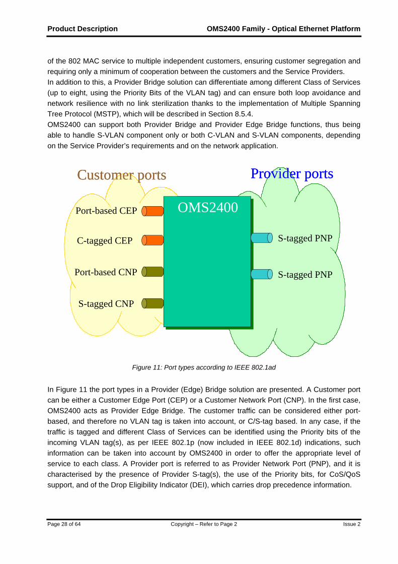
of the 802 MAC service to multiple independent customers, ensuring customer segregation and requiring only a minimum of cooperation between the customers and the Service Providers. In addition to this, a Provider Bridge solution can differentiate among different Class of Services (up to eight, using the Priority Bits of the VLAN tag) and can ensure both loop avoidance and network resilience with no link sterilization thanks to the implementation of Multiple Spanning Tree Protocol (MSTP), which will be described in Section 8.5.4. OMS2400 can support both Provider Bridge and Provider Edge Bridge functions, thus being able to handle S-VLAN component only or both C-VLAN and S-VLAN components, depending on the Service Provider’s requirements and on the network application.
Port-based CEP
C-tagged CEP
Port-based CNP
S-tagged CNP
S-tagged PNP
S-tagged PNP
Customer ports Provider ports
OMS2400Port-based CEP
C-tagged CEP
Port-based CNP
S-tagged CNP
S-tagged PNP
S-tagged PNP
Customer ports Provider ports
OMS2400
Figure 11: Port types according to IEEE 802.1ad
In Figure 11 the port types in a Provider (Edge) Bridge solution are presented. A Customer port can be either a Customer Edge Port (CEP) or a Customer Network Port (CNP). In the first case, OMS2400 acts as Provider Edge Bridge. The customer traffic can be considered either port-based, and therefore no VLAN tag is taken into account, or C/S-tag based. In any case, if the traffic is tagged and different Class of Services can be identified using the Priority bits of the incoming VLAN tag(s), as per IEEE 802.1p (now included in IEEE 802.1d) indications, such information can be taken into account by OMS2400 in order to offer the appropriate level of service to each class. A Provider port is referred to as Provider Network Port (PNP), and it is characterised by the presence of Provider S-tag(s), the use of the Priority bits, for CoS/QoS support, and of the Drop Eligibility Indicator (DEI), which carries drop precedence information.

OMS2400 – Optical Ethernet Platform Product Description
Issue 2 Copyright – Refer to Page 2 Page 29 of 64
In summary, a Provider Bridge solution allows to segregate the traffic of different customers, which can have different characteristics (untagged, C-tagged or S-tagged), and to treat it according to its requirements, with the possibility to support and properly transport up to eights Classes of Service. Unique Provider S-tags are used within the Provider network to offer the required connectivity to any Layer 2 service.
4.3 Q-in-Q support
OMS2400 family makes also available inter-working with and support of a Q-in-Q solution. In Figure 12 the scenario in which OMS2400 provides inter-working with existing Q-in-Q networks on the customer side is presented. In this case, OMS2400 is supposed to be used as a Provider (Edge) Bridge system, but with the additional capability to ensure inter-working with Q-in-Q clients, which will make use of CNP to access the Provider Bridge network.
CEP
CNP
Q-in-Q CNP
S-tagged PNP
S-tagged PNP
Customer ports Provider ports
OMS2400
IEEE 802.1adNetwork
CEP
CNP
Q-in-Q CNP
S-tagged PNP
S-tagged PNP
Customer ports Provider ports
OMS2400
IEEE 802.1adNetwork
Figure 12: Q-in-Q CNP in Provider Bridge
OMS2400 can also act as a “Tunnel Edge Bridge”, that is a system capable of initiating what can be called a Tunnel VLAN (T-VLAN), which is a per-customer port-based S-VLAN. This scenario is presented in Figure 13, where OMS2400 is supposed to have untagged or IEEE 802.1Q clients, and treat them using a port-based policy. From this brief description, it may be clear that QoS/CoS can be considered on a per-port basis only, resulting in a much more limited behaviour compared with an IEEE 802.1ad solution, yet this is in line with the concept of Tunnel VLAN that Q-in-Q promotes.

Product Description OMS2400 Family - Optical Ethernet Platform
Page 30 of 64 Copyright – Refer to Page 2 Issue 2
Client Port
T-tagged port
T-tagged port
Customer ports Provider ports
OMS2400
Client Port
Client Port “Q-in-Q”Network
Client Port
T-tagged port
T-tagged port
Customer ports Provider ports
OMS2400
Client Port
Client Port “Q-in-Q”Network
Figure 13: OMS2400 as “Tunnel Edge Bridge”
Please note that in Figure 13 the term T-tag instead of S-tag is used to indicate that the VLAN identifier is used in a Q-in-Q context.

OMS2400 – Optical Ethernet Platform Product Description
Issue 2 Copyright – Refer to Page 2 Page 31 of 64
5 Product Overview
5.1 System Design and mechanical solutions
The architecture of the OMS2400 family is based on a modular design solution. Depending on the amount of traffic, traffic growth anticipations, available space, and cost considerations, there is a choice of different sizes. The functionality of all shelves, of all interface cards and LTU’s, is essentially the same, with the main exception represented by OMS2410, whose single card architecture necessarily differs from the others. To cover the full range of applications, from smaller to large and ultimately to extended ones, the OMS2400 family provides different options. By combining the same family of units in most of the shelves, OMS2400 family can provide different systems, with their peculiar network positioning. • OMS2410 (Single card size) • OMS2430 (Compact size) • OMS2450 (Medium size) • OMS2470 (Large size) They will be described in the next paragraphs.
5.1.1 OMS2410
OMS2410 accommodates all components and units necessary to support CLE/Edge applications. It supports the following traffic modules:
Uplink module (4xGbE/STM-16, 1x10GbE/STM-64) Ethernet module (4xFE/GbE) CES module (4xSTM-1, 4x34Mbit/s, 8x2Mbit/s)
For more details about the maximum density of interfaces, please refer to the list given in Table 1. Please note that this list explains the maximum number for one interface type. In practice, several different interfaces will be accommodated simultaneously in the system.
Interface Type Max No. of ports Comment Fast Ethernet 8 GbE 16 10GbE 2 2 Mbit/s 16 34 Mbit/s 8 STM-1 8 STM-16 8 STM-64 2
Table 1: Number of interfaces offered by OMS2410

Product Description OMS2400 Family - Optical Ethernet Platform
Page 32 of 64 Copyright – Refer to Page 2 Issue 2
All traffic modules are hot pluggable, i.e. a traffic module can be removed and inserted in service without impairing existing traffic and can be immediately configured from a local or remote terminal.
5.1.1.1 OMS2410 layout
OMS2410 has full front access to all connectors. No fan tray is necessary for this single card equipment. In Figure 14 the layout of the equipment is given.
Figure 14: OMS2410 layout
5.1.2 OMS2430
OMS2430 accommodates all components and units necessary to support medium applications. It supports: • 8 traffic slots • 2 expansion slots
• Fabric-less switching capacity up to 40Gbit/s • Switching capacity up to 80 Gbit/s with central switch fabric • Protected Communication and Control Unit • Alarm Unit • Systems slots for power supply, clock, TMN and LCT access
For more details about the maximum density of interfaces, please refer to the list given in Table 2. Please note that this list explains the maximum number for one interface type. In practice, several different interfaces will be accommodated simultaneously in a shelf.
Max No. of ports Interface Type per card per shelf
Comment
Fast Ethernet 20 100 With port expansion. GbE 20 100 With port expansion. 10GbE 1 8 10 Gbit/s PoS 1 8 STM-1 8 64

OMS2400 – Optical Ethernet Platform Product Description
Issue 2 Copyright – Refer to Page 2 Page 33 of 64
STM-4 8 64 STM-16 4 32 STM-64 1 8
Table 2: Number of interfaces offered by OMS2430
All cards are hot pluggable, i.e. a card can be removed and inserted in service without impairing existing traffic and can be immediately configured from a local or remote terminal. The massive use of hot-pluggable optical and electrical modules (SFP and XFP) extends the hot plug-ability also at the individual port level.
5.1.2.1 OMS2430 Shelf
OMS2430 has full front access to all connectors. A fan tray is necessary for adequate equipment cooling, and it is located below the traffic cards.
Con
trol
&C
omm
s-A
Con
trol
&C
omm
s-B
Ala
rms
Mod
ule
4
Expa
nsio
n -0
1
Traf
fic S
lot -
04
Traf
fic S
lot -
05
Traf
fic S
lot -
06
Traf
fic S
lot -
07
Traf
fic S
lot -
08
5.5 5.5 5.5 5.5 5.5 5.5 5.5 5.5
CCUA
CCUB
T 8T 7T 6T 5T 4T 3E 2T 2
Cooling Fan + Air Filters
5 5
Switc
h -A
5.5
SA
Switc
h -B
5.5
SB
Traf
fic S
lot -
01
5.5
T 1
Expa
nsio
n -0
25.5
E 2
8
Bat
tery
B
8
Sync
h &
Man
agem
ent
Fibre Management
Traf
fic S
lot -
02
Traf
fic S
lot -
03
5.5
Bat
tery
A
Con
trol
&C
omm
s-A
Con
trol
&C
omm
s-B
Ala
rms
Mod
ule
4
Expa
nsio
n -0
1
Traf
fic S
lot -
04
Traf
fic S
lot -
05
Traf
fic S
lot -
06
Traf
fic S
lot -
07
Traf
fic S
lot -
08
5.5 5.5 5.5 5.5 5.5 5.5 5.5 5.5
CCUA
CCUB
T 8T 7T 6T 5T 4T 3E 2T 2
Cooling Fan + Air Filters
5 5
Switc
h -A
5.5
SA
Switc
h -B
5.5
SB
Traf
fic S
lot -
01
5.5
T 1
Expa
nsio
n -0
25.5
E 2
8
Bat
tery
B
8
Sync
h &
Man
agem
ent
Fibre Management
Traf
fic S
lot -
02
Traf
fic S
lot -
03
5.5
Bat
tery
A
Figure 15: OMS2430 shelf
In Figure 15 the characteristics of the shelf, with equipping indications, are given.
5.1.3 OMS2450
OMS2450 accommodates all components and units necessary to cover medium/large applications. It supports:
• 12 traffic slots • 10 traffic LTU’s • Protected packet switch fabric (up to 160 Gbit/s)

Product Description OMS2400 Family - Optical Ethernet Platform
Page 34 of 64 Copyright – Refer to Page 2 Issue 2
• Protected Communication and Control Unit • Alarm Unit • System Line Terminating Units (LTU’s) for power supply, clock, TMN and LCT access
In Table 3 a list with the maximum density of principal interfaces is given. Please note that this list explains the maximum number for each interface type. In a real application, there will be a number of different interfaces simultaneously in each shelf.
No. of ports Interface Type per card per shelf
Comment
Fast Ethernet 20 220 With port expansion via LTU. GbE 20 220 With port expansion via LTU. 10GbE 2 16 Using 1x10GbE and 2x10GbE cards. 10 Gbit/s PoS 1 12 STM-1 8 96 STM-4 8 96 STM-16 4 48 STM-64 1 12
Table 3: Number of interfaces offered by OMS2450
All cards are hot pluggable, i.e. a card can be removed and inserted in service without impairing existing traffic and can be immediately configured from a local or remote terminal. The massive use of hot-pluggable optical and electrical modules (SFP and XFP) extends the hot plug-ability also at the individual port level.
5.1.3.1 OMS2450 Shelf
OMS2450 has full front access to all connectors. Some connectors are directly located on the front of the unit, others are accessible via the LTU area.

OMS2400 – Optical Ethernet Platform Product Description
Issue 2 Copyright – Refer to Page 2 Page 35 of 64
Bat
tery
LTU
- B
Bat
tery
LTU
- A
T1
Traf
fic S
lot -
01
5.5
T2
Traf
fic S
lot -
02
5.5
T3
Traf
fic S
lot -
03
5.5
T4
Traf
fic S
lot -
04
5.5
T5
Traf
fic S
lot -
05
5.5
T6
Traf
fic S
lot -
06
5.5
SA
Switc
h - A
5.5
SB
Switc
h - B
5.5
T7
Traf
fic S
lot -
07
5.5
T8
Traf
fic S
lot -
08
5.5
T9Tr
affic
Slo
t - 0
9
5.5
T10
Traf
fic S
lot -
10
5.5
T11
Traf
fic S
lot -
11
5.5
T12
Traf
fic S
lot -
12
5.5
CCUA
Con
trol &
Com
ms
5
CCUB
Con
trol &
Com
ms
5
AL
Ala
rms a
nd M
ngm
t
4Tr
ib L
TUTr
ib L
TUTr
ib L
TU
Trib
LTU
MG
MT
Trib
LTU
Trib
LTU
Trib
LTU
Trib
LTU
SYN
C
Spar
e Sl
ot
Sp
Fibre Management and Filters
4
Trib
LTU
Trib
LTU
PSU
- A
PSU
- B
Cooling Fans
Figure 16: OMS2450 shelf
A fan tray is necessary for adequate equipment cooling, and it is located below the LTU area. In Figure 16 the characteristics of the shelf, with equipping indications, are given.
5.1.4 OMS2470
OMS2470 accommodates all components and units necessary to support large and very large applications. It supports:
• 16 traffic slots • 10 expansion/protection slots • 6 traffic slots, out of the 16, can be used also for protection purposes. • Protected packet switch fabric, up to 320 Gbit/s • Protected Communication and Control Unit • Alarm Unit • Systems slots for power supply, clock, TMN and LCT access
For more details about the maximum density of interfaces, please refer to the Table 4. Please note that this list explains the maximum number for one interface type. In practice, several different interface types will be accommodated simultaneously in a shelf.
Interface No. of ports Comment

Product Description OMS2400 Family - Optical Ethernet Platform
Page 36 of 64 Copyright – Refer to Page 2 Issue 2
Type per card per shelfFast Ethernet 20 260 With port expansion. GbE 20 260 With port expansion. 10GbE 2 32 10 Gbit/s PoS 2 32 STM-1 8 128 STM-4 8 128 STM-16 4 64 STM-64 2 32
Table 4: Number of interfaces offered by OMS2470
The massive use of hot-pluggable optical and electrical modules (SFP and XFP) extends the hot plug-ability also at the individual port level.
5.1.4.1 OMS2470 Shelf
OMS2470 has full front access to all connectors, which are directly located on the front of the units. Fan trays are necessary for adequate equipment cooling, and they are located above each of the two rows of cards. In Figure 17 the characteristics of the shelf, with equipping indications, are given. The packet switch fabric of OMS2470 is composed of a primary unit and a secondary unit, which are protected using a 1:2 scheme. The Communications and Control Unit has a 1+1 redundancy.

OMS2400 – Optical Ethernet Platform Product Description
Issue 2 Copyright – Refer to Page 2 Page 37 of 64
Ala
rms
Al
4
Cooling Fans
Fibre Management and Filters
Fibre Management
Cooling Fans
Con
trol &
Com
ms
Bat
tery
PSU
–A
1B
atte
ry P
SU –
B1
T1
Traf
fic S
lot 0
1
5.5
T2
Traf
fic S
lot 0
2
5.5
T4
Traf
fic S
lot
04 -
Prot
5.5
E5Ex
pans
ion/
Prot
ectio
n
5.5
Expa
nsio
n/Pr
otec
tion
E7
Expa
nsio
n/Pr
otec
tion
5.55.5
E6 T8
Traf
fic S
lot
08 -
Prot
5.5
PS
Prot
ectio
n S
witc
h
5.5
Expa
nsio
n/Pr
otec
tion
5.5
E9 T10
Traf
fic S
lot 1
0 -P
rot
5.5
T12
Traf
fic S
lot 1
2
5.5
T13
Traf
fic S
lot 1
3
5.5
T14
Traf
fic S
lot 1
4
5.5
T15
Traf
fic S
lot 1
5
5.5
Con
trol &
Com
ms
CCU B
5
Bat
tery
PSU
–A
2B
atte
ry P
SU –
B2
Fibre Management
E1
Expa
nsio
n/Pr
otec
tion
5.5
E2
Expa
nsio
n/Pr
otec
tion
5.5
T3
Traf
fic S
lot
03 -
Prot
5.5
T5
Traf
fic S
lot 0
5
5.5
T6
Traf
fic S
lot 0
6
5.5
T6
5.5
Traf
fic S
lot 0
7
T9
Traf
fic S
lot -
09
5.5
T11
Traf
fic S
lot
11 -
Prot
5.5
E12
Expa
nsio
n/Pr
otec
tion
5.5
E13
5.5
Man
agem
ent -
Sync
h
Mgmt-Synch
8
T16
Traf
fic S
lot
16 -
Prot
5.5
E14
5.5
CCU A
5 5.5
T7
Prim
ary
Switc
h
PS
5.5
Seco
ndar
y Sw
itch
SS
5.5
Expa
nsio
n/Pr
otec
tion
Expa
nsio
n/Pr
otec
tion
Expa
nsio
n/Pr
otec
tion
5.5
E15
Figure 17: OMS2470 shelf

Product Description OMS2400 Family - Optical Ethernet Platform
Page 38 of 64 Copyright – Refer to Page 2 Issue 2
6 Interfaces
6.1 Data Traffic Units
Since the OMS2400 family is devoted to carrier class packet transport, the data traffic units are of great importance on both client and trunk sides. The OMS2400 family in fact supports the native transport of the data traffic, and therefore the Ethernet interfaces, in all their possible variants, are both clients and trunk lines. In this way the OMS2400 product family allows operators to build cost-effective networks able to support the more sophisticated services with the maximum flexibility. OMS2400 provides also a card protection mechanism for client Ethernet interfaces.
10 Gbit/s Traffic Units Interfaces on the Unit Expansion Interfaces
Fast Ethernet 10 10 Gigabit Ethernet 10 10 10 Gigabit Ethernet 1 - 10 Gbit/s PoS 1 -
20 Gbit/s Traffic Units Interfaces on the Unit Expansion Interfaces
Gigabit Ethernet 10 10 10 Gigabit Ethernet 2 - 10 Gbit/s PoS 2 -
Table 5: Data traffic units offered by OMS2400 family
Table 5 shows the maximum number of interfaces on the two different versions of Ethernet cards available on the OMS2400 family, assuming over-subscription in some cases. Please note that Fast Ethernet and Gigabit Ethernet traffic can be mixed together in each card. The data interfaces come in different variants, in accordance with IEEE 802.3:
Fast Ethernet: 10/100Base-TX, 100Base-FX, 100Base-LX10 Gigabit Ethernet: 1000Base-T, 1000Base-SX, 1000Base-LX10, 1000Base-ZX 10 Gigabit Ethernet: 10GBase-SR, 10GBase-LR, 10GBase-ER, 10Gbase-ZR (proprietary
long reach), 10GBase-SW, 10GBase-LW, 10GBase-EW, 10Gbase-ZW (proprietary long reach).
There are also variants able to support single fibre working (100Base-BX-10-D/U, 1000Base-BX-10-D/U), as per IEEE 802.3.
6.2 SDH Traffic Units
These interfaces carry the optical STM signals from and to the OMS2400 family equipment. Also in case of SDH interfaces, pluggable modules are used, SFP for STM-1, STM-4 and STM-16, and XFP for STM-64. In Table 6 the various options are listed.

OMS2400 – Optical Ethernet Platform Product Description
Issue 2 Copyright – Refer to Page 2 Page 39 of 64
STM-64 Comment
Number of interfaces per unit 1 Optical Interfaces according to ITU-T G.691/959.1 I-64.1r, I64-2r, S-64.1, S-64.2b, L64.2 Wavelength 1310 nm or 1550 nm
STM-16 Comment
Number of interfaces per unit 4 Optical Interfaces according to ITU-T G.957/G.691 I-16, S-16.1, L-16.1, L16.2, V-16.2 Wavelength 1310 nm or 1550 nm
STM-4 Comment
Number of interfaces per unit 8 Optical Interfaces according to ITU-T G.957 S-4.1, L-4.1, L-4.2 Wavelength 1310 nm or 1550 nm
STM-1 Comment
Number of interfaces per unit 8 Optical Interfaces according to ITU-T G.957 S-1.1, L-1.1, L-1.2 Wavelength 1310 nm or 1550 nm
Table 6: SDH traffic units offered by OMS2400 family
6.3 System Units
6.3.1 Packet Switching Unit (OMS2430, OMS2450 and OMS2470)
The core of the system is a packet switch fabric. This can switch both data packets and SDH VCs with the required granularity, thus optimising the performances and the capability of the whole system. The capability of switching SDH VCs can be achieved by means of equipping devoted SDH tributary traffic cards. The circuitry to distribute the synchronisation signals to SDH line cards is included in the central switch fabric. OMS2400 family has a centralised packet switching unit (optional in case of OMS2430), with 80 Gbit/s (OMS2430), 160 Gbit/s (OMS2450) and 320 Gbit/s capacity (OMS2470) respectively. The switch fabric is agnostic of the specific service. In fact, ingress and egress traffic management is integrated in the traffic cards, for an even higher degree of flexibility and to allow the maximum evolution capability. The switch fabric is characterised by a dynamic routing over a Clos interconnect architecture, and therefore it represents a non-blocking and fault-tolerant solution. The switch fabric sustains any traffic pattern without decreasing performances (delay, jitter and loss probability) and has HW-based self-healing characteristics with detection, isolation and

Product Description OMS2400 Family - Optical Ethernet Platform
Page 40 of 64 Copyright – Refer to Page 2 Issue 2
repair. The routing inside the switch fabric is dynamic, with the possibility to set up non-interfering routes through the switching architecture for a new input-output connection, given any configuration of existing connections. This means that no re-arrangement of existing routes is ever required. Furthermore, the traffic load is internally balanced, thus facilitating the implementation of highly efficient fault tolerant schemes. The architecture is capable of reassembling packets at the output of the switch fabric, thus preventing out-of-order arrivals, which may be possible in dynamically routed architectures. In Figure 18 a schematic view of the switch fabric connections is given. The traffic cards are traffic aware, which means that, along with the fabric access, they include traffic management, thus supporting a variety of functionality, like queuing and scheduling.
TrafficManager
&Fabric Access
TrafficManager
&Fabric Access
Service Agnostic Fabric
Traffic card 1
FABRIC
ServiceAwareTrafficCards
TrafficManager
&Fabric Access
Traffic card N
Figure 18: Schematic view of switch fabric connections
In this way, the system architecture is extremely flexible, scalable and open to future upgrades and to support new services possibly with new and different requirements.

OMS2400 – Optical Ethernet Platform Product Description
Issue 2 Copyright – Refer to Page 2 Page 41 of 64
Fabric plane
Fabric plane
Fabric plane
Input ProcessorQueue Controller
Input ProcessorQueue Controller
Output ProcessorScheduler
Output ProcessorScheduler
Switch fabric unit
Ingress traffic Egress traffic
Traffic card 1
Traffic card N
Traffic card 1
Traffic card N
Figure 19: Some details of the switching architecture
In Figure 19 some high-level details of the functional switching architecture are shown. The ingress and egress interfaces to the switching fabric reside in the traffic cards, and integrate the functionality of ingress Queue Controller and of output Scheduler. The packets, of variable size, are buffered at the ingress in thousands of virtual output queues, which are stored in external DRAM memory. These queues may be arbitrarily attached to destination ports, thus enabling a per-flow queuing scheme. An output Scheduler is associated with each port, and distributes the network port’s output bandwidth among the competing queues. The packet switch unit can be protected, of course, in order to prevent the system from experiencing troubles or traffic interruptions deriving from unrecoverable fault situations.
6.3.2 Fabric-less Packet Switching capability (OMS2430)
OMS2430 is the compact version of OMS2400 family. For this reason, it has been designed to be operational also without the presence of a centralised packet switching unit. The 40 Gbit/s switching capacity is obtained by a fabric-less configuration, with direct interconnection via fabric interfaces. In Figure 20 the concept of the switching architecture of OMS2430 is given. Each traffic card is interconnected with the others in a meshed configuration, thus ensuring the possibility to reach any output port from any input port. As in the fabric-based architecture, the traffic cards retain the traffic management capability, providing the same functionality, such as

Product Description OMS2400 Family - Optical Ethernet Platform
Page 42 of 64 Copyright – Refer to Page 2 Issue 2
queuing and scheduling. In this way the fabric-less architecture is functionally equivalent to the fabric-based architecture, but limited at a maximum of 40 Gbit/s switching capacity.
Input ProcessorQueue Controller
Input ProcessorQueue Controller
Output ProcessorScheduler
Output ProcessorScheduler
Back plane interconnections
Ingress traffic Egress traffic
Output ProcessorScheduler
Output ProcessorScheduler
Figure 20: Fabric-less packet switching architecture
Since OMS2430 is the system of the product family which is targeted for the lower part of the network, it is expected to provide an even higher degree of flexibility, in order to provide the best technical solution at the minimum cost. In Figure 21 the equipping characteristics of the mesh configuration are given. For example, two lines can be hypothesised (in a classical east-west ring scenario), with two tributary traffic units, each with its expansion card aside. In this example, the lines could likely be 10GbE signals, and the total tributary signals can be up to 40 GbE/FE.

OMS2400 – Optical Ethernet Platform Product Description
Issue 2 Copyright – Refer to Page 2 Page 43 of 64
Ala
rms
Mod
ule
4
Expa
nsio
n -0
1
Traf
fic S
lot -
04
Traf
fic S
lot -
05
Traf
fic S
lot -
06
5.5 5.5 5.5 5.5 5.5
T 6T 5T 4T 3E 2
Cooling Fan + Air Filters
Pass
ive
Inte
rcon
nect
-A
5.5
A
Pass
ive
Inte
rcon
nect
-B
5.5
B
Expa
nsio
n -0
2
5.5
E 2
8
Bat
tery
B
8
Sync
h &
Man
agem
ent
Fibre Management
Traf
fic S
lot -
03
5.5
Bat
tery
A
Figure 21: OMS2430 – Mesh configuration (up to 40 Gbit/s capacity).
In Figure 22 the connection characteristics of 2430 in case of central switch are given.
Traf
fic S
lot -
01
Traf
fic S
lot -
02
Expa
nsio
n Sl
ot -
01
Traf
fic S
lot -
03
Traf
fic S
lot -
04
Switch -A
Switch -B
Traf
fic S
lot -
08
Traf
fic S
lot -
07
Expa
nsio
n Sl
ot -
02
Traf
fic S
lot -
06
Traf
fic S
lot -
05
80 Gbit/s Switch(1:1 redundancy)
Connection with Expansion Slots Allows higher Port count
Additional Port Count for Slot 02 and 07 using Slot 01 and Slot 08 as expansion slots respectively
Traf
fic S
lot -
01
Traf
fic S
lot -
02
Expa
nsio
n Sl
ot -
01
Traf
fic S
lot -
03
Traf
fic S
lot -
04
Switch -A
Switch -B
Traf
fic S
lot -
08
Traf
fic S
lot -
07
Expa
nsio
n Sl
ot -
02
Traf
fic S
lot -
06
Traf
fic S
lot -
05
80 Gbit/s Switch(1:1 redundancy)
Connection with Expansion Slots Allows higher Port count
Additional Port Count for Slot 02 and 07 using Slot 01 and Slot 08 as expansion slots respectively
Figure 22: OMS2430 –Configuration with central switch (80 Gbit/s capacity)
For example, two lines for can be assumed (in a classical east-west ring scenario), with six tributary traffic units. The lines could likely be 10GbE signals, and the tributary signals could be up to 80 GbE/FE, or a mix of the two. Also SDH interfaces are possible. Please note that, if needed, two traffic slots (01 and 08) can be used as expansion slots.

Product Description OMS2400 Family - Optical Ethernet Platform
Page 44 of 64 Copyright – Refer to Page 2 Issue 2
6.3.3 Fabric-less Packet Switching capability (OMS2410)
OMS2410 is characterised by a compact single card architecture where all required functions are performed by the network processor with no need of dedicated switch fabric. In Figure 23 the concept of OMS2410 architecture is given. All traffic modules are connected to the core block performing both traffic processing (i.e. traffic aggregation and switching) and traffic management including queuing and scheduling functionality of the output traffic.
NP +
Traffic Manager
Ethernet Module
UpLink Module
UpLink Module
Ethernet Module
CES Modules
CES Modules
Figure 23: OMS2410 architecture
6.3.4 Communication and Controller Unit
The Communication and Controller Unit includes the main CPU to control all activities and provides management functions and connection facilities to ServiceOn Network Management System. In addition it provides housekeeping user contacts, inputs and outputs for remote control of customer location. The CCU is based on a general-purpose processor devoted to perform the following main tasks:
Equipment management, including detection and configuration Alarm management Software download, comprising the management of the different software versions available
for each unit present in the shelf, and allowing the possibility to download new versions of software in the network element, and to switch between old and new software in a non-traffic-affecting way
Management of the unit protection schemes, allowing to implement 1+1 protection of the common parts, including CCU itself and the switch units
Management of the services, circuits, flows and protocol parameters, allowing to properly configure services on the OMS2400 family
Run the centralised part of the protocol stack, managing messages and events coming from the traffic units and commands coming from the management, and generating configuration actions towards the traffic units.

OMS2400 – Optical Ethernet Platform Product Description
Issue 2 Copyright – Refer to Page 2 Page 45 of 64
CPU
MediaSwitch
MediaSwitch
1 Gb/s
UnitUnit UnitUnit UnitUnit UnitUnit…. ….
DB
100 Mb/s 100 Mb/s
Management
To RedundantCCU100 Mb/s
CCU
CPU
Figure 24: CCU architecture
Dual processor architecture has been adopted to achieve greater computing power and to keep separated the management functions from the real time traffic protocols. In Figure 24 the architecture of the CCU is presented.
6.4 External System Interfaces
6.4.1 Power Supply Interfaces
Distributed PSU‘s operate at a nominal battery voltage of –48V and –60V. The connection to the battery can be protected. During external power break down less than 16ms the integrated buffer capacity will ensure an error free operation.
6.4.2 Control and Communication (Management) Interface
The Communication and Controller Unit provides the complete microprocessor-based management system for OMS2400 family equipment, supporting both Equipment Management Functions and Management Communications Functions. The Communication and Controller Unit supports the interface for Local Terminal access and the interface for NMS access. The OMS2400 family can also support «in-band» management communication channel, equivalent to the Qecc interface of SDH technology, by means of a dedicated management LSP.

Product Description OMS2400 Family - Optical Ethernet Platform
Page 46 of 64 Copyright – Refer to Page 2 Issue 2
7 Equipment protections OMS2400 family has been designed in order to guarantee the highest level of availability. All common parts of the equipment can therefore be fully duplicated. Also card protection is provided for client Ethernet traffic units. All the common parts of the equipment are fully duplicated. In addition, the functionality of the equipment is monitored by an alarm system and by built-in test patterns, which allow all of the paths between the ports to be monitored in service without affecting traffic in any way. The protected units within the equipment are: Switch fabric (and Timing) Communication and Controller Unit Power Supply Cooling system

OMS2400 – Optical Ethernet Platform Product Description
Issue 2 Copyright – Refer to Page 2 Page 47 of 64
8 Traffic Protection, OAM and Resilience mechanisms The OMS2400 family has been conceived and designed for a carrier class transport of data traffic. This means that, alongside flexibility and versatility characteristics typical of data equipment, the OMS2400 family makes available to network operators all the OAM and protection features that are needed to enable a reliable and robust transport. Protection mechanisms have been implemented on both client and trunk sides. In this Section, MPLS OAM and protections, restoration mechanisms, Ethernet OAM and protections, Link Aggregation, Spanning Tree protocol, SDH protections and Control Plane resilience are described.
8.1 MPLS OAM and Protection Mechanisms
8.1.1 MPLS OAM
MPLS OAM is used to monitor the LSP’s status in an MPLS network. In this way, defect detection, identification, localisation and handling can be put in place, along with defect handling and alarm suppression. Hence, switching criteria can be identified and protection mechanisms realised. MPLS OAM is based on OAM packets, which have been conceived to facilitate ease of processing and to support minimum size requirements of current L2 technologies, like Ethernet. Each OAM packet uses a BIP16 to detect errors. BIP16 processing must be performed on all OAM packets prior to any further processing of their payload. OAM packets are essentially divided into two main functional categories: those devoted to connectivity verification (CV, Connectivity Verification; FFD, Fast Failure Detection) and those in charge of defect indication (FDI, Forward Defect Indication; BDI, Backward Defect Indication). The CV flow is generated at the LSP’s source with a nominal frequency of 1/s and is terminated at the LSP’s sink. The CV packet contains a network unique identifier (TTSI, Trail Termination Source Identifier), which is composed of the source LSR identifier and the LSP identifier, so that all types of defects can be detected. The CV function serves to detect/diagnose all types of LSP connectivity defects, which origin from either the MPLS layer or below. FFD packets contain the same information as CV packets, but they can be generated at higher frequency, with a default value of 20 Hz, as per ITU-T Recommendation Y.1720. FFD is used to detect connection verification at a smaller time scale, and its use is recommended at the lower MPLS level (which is 1), with no CV LSP serving FFD LSP, as shown in Figure 25.

Product Description OMS2400 Family - Optical Ethernet Platform
Page 48 of 64 Copyright – Refer to Page 2 Issue 2
Source LER Sink LERSink LERLSR LSR
Server LSP (level 1)
Client LSP (level 2) CV
FFD
Figure 25: CV and FFD LSP’s
The FDI flow is generated in response to detecting defects (e.g. from the FFD flow), and its primary purpose is to suppress alarms in network layers above that at which the defect occurs. The FDI flow is generated either at the LSR that first detects a defect or at the LSP terminating LSR for all MPLS layer defects. Its primary purpose is to suppress alarms being raised at affected higher level client LSP’s and their client layers. It also includes fields to indicate the nature of the defect and its location. The BDI flow is injected on the return path, such as a return LSP, to inform the upstream LSR, which is the source of the forward LSP, that there is a defect at the downstream LSP’s LSR sink point. The BDI function informs the upstream end of an LSP of a downstream defect. To do this a return path is required. The BDI functionality is useful in applications such as single-ended measurements for performance, or to provide an indication for certain types of protection switching. In Figure 26 a visualisation of the FDI/BDI mechanism is given in case of a physical failure.

OMS2400 – Optical Ethernet Platform Product Description
Issue 2 Copyright – Refer to Page 2 Page 49 of 64
Source LER Sink LERSink LERLSR 1 LSR 2
BDI
Downstream Server LSPUpstream Server LSP
NearEnd DefectFarEnd Defect
Physical Failure
Transit LSR detects the physical failure.BDI/FDI message are sent upstream for
both Server and Client LSPs.Downstream Client LSPUpstream Client LSP
BDIFDIFDI
FDI
Figure 26: FDI and BDI in case of physical failure
OAM is required to detect and diagnose broken LSP’s, to perform path characterisation and SLA measurements (like availability, latency, packet loss, jitter) and alarm suppression.
Source LER Sink LERLSR 1 LSR 2
LSP level NLSP level N+1
The LSP at layer N+1 has the only purpose ofmonitoring the LSP at layer N.
Figure 27: Use of LSP at layer N+1 to monitor a segment of LSP at layer N
OAM techniques are applied end to end on a per LSP basis. If a segment at layer N has to be monitored for some reason (e.g. when an LSP passes through different administrative or

Product Description OMS2400 Family - Optical Ethernet Platform
Page 50 of 64 Copyright – Refer to Page 2 Issue 2
operational domains), a possible solution is to create a new server layer LSP (layer N+1) for the specific segment at layer N. This concept is shown in Figure 27.
8.1.2 MPLS Protections
The MPLS protection switching architecture can basically be of three types: 1+1, 1:1 or 1+1 packet, as described in Recc. ITU-T Y.1720. In the 1+1 type of architecture, a protection LSP is dedicated to each working LSP, with the working entity bridged onto the protection entity at the source of the protection domain. The traffic on working and protection LSP’s is transmitted simultaneously to the sink of the protection domain, where a selection between the working and protection entities is made based on some predetermined criteria, such as defect indication. In the 1:1 architecture type, a protection LSP is dedicated to each working LSP, but the protection LSP actually carries the protected traffic only in case of failure. In the 1+1 packet type of protection, the traffic is fed onto both LSP’s, like in the 1+1 scheme, but the selection of incoming packets from any of the two LSP’s is irrespective of the LSP from which the last packet was selected. This means that 1+1 packet protection treats both LSP’s as working, with no designation of a working LSP and a protection LSP.
8.1.2.1 1+1 Protection
The 1+1 linear protection switching architecture is unidirectional and therefore the protection switching is performed by the selector at the sink of the protection domain based on purely local information.
Packet Switched Network
Protection LSP
Working LSP
Packet Switched Network
Switch on protection LSP
Protection LSP
Working LSP
Protected signal
OAM packet insertion [CV/FFD]
OAM packet extraction
Ingress OMS2400
Egress OMS2400
Permanent Bridge
Selector
Protected signal
OAM packet insertion [CV/FFD]
OAM packet extraction
Ingress OMS2400
Egress OMS2400
Figure 28: LSP 1+1 protection

OMS2400 – Optical Ethernet Platform Product Description
Issue 2 Copyright – Refer to Page 2 Page 51 of 64
As shown in Figure 28, the working traffic is permanently bridged to working and protection LSP’s at the source of the protection domain. OAM packets (CV/FFD) can be used to detect defects of working and protection LSP’s, and they have to be inserted at the source of the protection domain on both working and protection LSP’s, and extracted at the sink of the protection domain, where the switching decision is taken.
8.1.2.2 1:1 Protection
In the 1:1 linear protection switching architecture is similar to the 1+1 protection scheme there is no permanent bridging at the source of the protection domain, and the protection switching is performed by the selector at the source of the protection domain based on local information.
Packet Switched Network
Switch on protection LSP Protection LSP
Working LSP
Protected signal
OAM packet insertion [CV/FFD]
OAM packet extraction
Ingress OMS2400
Egress OMS2400
Packet Switched Network
Permanent Bridge or Selector
Selector Protection LSP
Working LSP
Protected signal
OAM packet insertion [CV/FFD]
OAM packet extraction
Ingress OMS2400
Egress OMS2400
Figure 29: LSP 1:1 protection without extra traffic
As shown in Figure 29, working and protection traffic is permanently merged at the sink of the protection domain. If a problem occurs to the working LSP, this defect is detected at the sink of the protection domain and then reported to the source of the protection domain (using the appropriate OAM packets, i.e. BDI). The selector at the protection domain source switches to the protection LSP on reception of this report.
8.1.3 Packet 1+1 protection switching
Packet 1+1 path protection provides a packet level protection service similar in some respects to the conventional 1+1 protection mechanism with the essential difference that packet 1+1

Product Description OMS2400 Family - Optical Ethernet Platform
Page 52 of 64 Copyright – Refer to Page 2 Issue 2
protection allows selection of incoming packets from any connection, irrespective of the connection from which the last packet was selected. Packet 1+1 protection does not designate one connection as working and the other as protecting, and therefore it does not require explicit failure detection and protection switching. This allows such a scheme to recover from any failure instantaneously and transparently. Only edge nodes need to be service-aware. To provide packet 1+1 protection service between two nodes in a MPLS network, a pair of LSP’s is established between them along disjoint paths. At the egress edge node, one of the two copies of the packets is selected from the two possible received copies, and forwarded. This allows the service to withstand a single failure transparently. In terms of restoration time, this can be characterised as an instantaneous recovery from a failure since there is no need to detect, notify and switch to a protection path explicitly.
8.2 Restoration mechanisms
Two restoration mechanisms are actually foreseen for OMS2400 family. They are LSP Restoration and Fast Re-Route (FRR). They have been implemented according to latest IETF indications, and are meant to provide network operators with the widest range of instruments, in addition to those described in Section 8.1, to build reliable networks according to their specific reality and requirements.
8.2.1 LSP Restoration
LSP Restoration is defined in RFC3469. It is a method of global repair, in the sense that an alternative LSP tunnel (either pre-established or established on demand) is used in case of failure condition on the primary LSP tunnel. The intent of global repair is to protect against any link or node fault on a path or on a segment of a path, with the obvious exception of the faults occurring at the end nodes of the protected path segment. In global repair, end-to-end path recovery/restoration applies. The recovery path can be made completely link and node disjoint with its working path, with the advantage of protecting against all link and node fault(s) on the working path (end-to-end path or path segment). As a result, the ingress node, which needs to be informed from downstream about the failure, is responsible to actually switch traffic onto the backup LSP, according the defined policy. In case of recovery LSP tunnel established on demand, it can be either pre-computed or computed on demand.

OMS2400 – Optical Ethernet Platform Product Description
Issue 2 Copyright – Refer to Page 2 Page 53 of 64
Primary LSP
Backup LSP
Protected signal
Ingress OMS2400
Egress OMS2400“Switch” to
Backup LSP
Primary LSP
Backup LSP
Protected signal
Ingress OMS2400
Egress OMS2400“Switch” to
Backup LSP
Figure 30: Example of LSP Restoration
In Figure 30 a schematic example of LSP Restoration is given. In the example, the egress node is informed about the failure occurred to the protected LSP (it can also realise it at the physical layer, depending on the network planning and characteristics) and sends back a notification to the ingress node in order to enable the switch to backup LSP. Due to different timing requirements, Restoration mechanisms can cohabit with protection mechanisms. In case of coexisting 1+1 protection mechanisms, it can be advantageous, as in the example given in Figure 30, to let the egress node notify the ingress node, if the case (i.e. if Restoration switch has to be really performed for that LSP in that moment).
8.2.2 Fast Re-Route
FRR is the mechanism of local repair defined in RFC4090, and conceived to act fast to locally by-pass a failure. The timing requirement is satisfied by computing and signalling backup LSP tunnels in advance of failure and by re-directing traffic as close to the failure point as possible. In this way, the time for redirection includes no path computation and no signalling delays, including delays to propagate failure notification between nodes. Taking advantage of the MPLS label stack, the facility backup method allows the Point of Local Repair (PLR), which is the node responsible of detecting the failure and taking the consequent action, to create a single bypass tunnel that can be used to protect multiple LSPs.

Product Description OMS2400 Family - Optical Ethernet Platform
Page 54 of 64 Copyright – Refer to Page 2 Issue 2
Primary LSP
Bypass tunnel (Link failure)
IngressOMS2400
EgressOMS2400
Bypass tunnel (Node failure)
Primary LSP
EgressOMS2400
Point of LocalRepair
Point of LocalRepair
MergePoint
MergePoint
Primary LSP
Bypass tunnel (Link failure)
IngressOMS2400
EgressOMS2400
Bypass tunnel (Node failure)
Primary LSP
EgressOMS2400
Point of LocalRepair
Point of LocalRepair
MergePoint
MergePoint
Figure 31: Example of Fast Re-Route mechanisms
In Figure 31 an example of FRR mechanisms is given. In the upper part of the figure, a link failure is supposed to occur, and therefore the Point of Local Repair and the Merge Point (the node where one or more backup tunnels rejoin the path of the protected LSP downstream of the potential failure) can be adjacent along the protected LSP path. In the lower part of the figure, instead, the case of nodal fault is presented, where the Point of Local Repair and the Merge Point cannot of course be adjacent along the protected LSP path.
8.3 Ethernet OAM and Protection Mechanisms
OAM functionality is important in public networks for ease of network operation, to check network performance, and to reduce operational costs. OAM functionality is especially important for networks that are required to deliver (and hence to be measurable against) network performance and availability objectives. In order to offer a reliable Ethernet service that can support the requirements of a Service Level Agreement, it is necessary that the Ethernet service incorporate its own OAM capabilities. The major motivations for Ethernet OAM are as follows.
There can be failure modes that are only relevant to Ethernet, and, in general, lower-layer (server-layer) or higher-layer (client-layer) OAM mechanisms cannot act as a substitute for Ethernet OAM functionality. This observation is also critical to ensure that network technologies can evolve independently.

OMS2400 – Optical Ethernet Platform Product Description
Issue 2 Copyright – Refer to Page 2 Page 55 of 64
Operators need to determine Ethernet availability and network performance. This information may also be used for accounting and billing purposes to ensure that customers are not inappropriately charged for degraded service or service outages.
Reduce operating costs, by allowing efficient detection, handling, and diagnosis of defects. Lack of automatic defect detection and handling forces operators to increase their engineering and support workforce, and hence increases overall operating costs.
Reduce the duration of defects, thus increasing availability. Provide customer traffic security/confidentiality by ensuring that any misconnection defects
will be detected and diagnosed, with the appropriate consequent actions. Minimise the number of defects that are not automatically detected and still require a
customer to report a problem. Allow differentiation between defects arising from lower layers and defects from within the
Ethernet layered network, so that more intelligent protection-switching actions can be used.
8.3.1 OAM functions
The necessary OAM functions are as follows: Continuous Connectivity Check (CC) Alarm suppression Intrusive loopback (point-to-point services only) and non-intrusive loopback Path trace Discovery Performance monitoring Survivability (e.g., protection switching, restoration, etc.)
8.4 Link Aggregation
Link Aggregation is a functionality specified in IEEE 802.3-2002 (formerly in superseded IEEE 802.3ad), where procedures to aggregate one or more links/ports together to form a logical link (aggregation group) are defined. This aggregation group is presented as a single logical link to higher layer protocols such as MAC clients. This allows to build large bandwidth logical links of higher availability. The inner working of client and server applications are completely transparent to this abstraction provided by aggregation. In the OSI model, link aggregation is located above the data link layer and below the network layer. Some of the important features of Link Aggregation are: Increased or higher bandwidth through the use of existing infrastructure Increased system resiliency and recovery: aggregation of lower-bandwidth links provide
continuity of operations even under failure of one or more links in the aggregation group Optional support for load balancing of network traffic across all of the links in the
aggregation group Support for automated mechanism Customisation of load balancing through use of distribution functionality Coexistence of aggregated and non-aggregated links

Product Description OMS2400 Family - Optical Ethernet Platform
Page 56 of 64 Copyright – Refer to Page 2 Issue 2
Dynamic negotiation capabilities to form link aggregation between peers Interoperability with aggregation unaware devices Minimisation of disruption to higher layers in the event of links failure through the use of
aggregator groups Retention of packet ordering No additional requirements or changes to the existing higher layer protocol such as MAC
clients Management support to configure, monitor and control link aggregation
Link Aggregation can be managed either manually or through the Link Aggregation Control Protocol (LACP). Manual aggregation allows creation of statically aggregated port groups with no communication with the peer. LACP, on the other hand, allows dynamic formation of aggregated port groups. In this case, the participating peers reach a consensus on what ports can be aggregated. The major functions of LACP are: Maintain configuration information to control aggregation Exchange configuration information with other systems to dynamically allocate a link to a
group Attach and detach a port to aggregation group Automatic and continuous detection and corrections of aggregation groups Monitoring and maintenance of aggregator group status through period communication with
the peer OMS2400 family provides Link Aggregation on Ethernet client ports, as indicated in Figure 32.
Logical Link(Aggregation Group)
Physical Link
Physical Link
Physical Link
CLIENT
OMS2400
Logical Link(Aggregation Group)
Physical Link
Physical Link
Physical Link
CLIENT
OMS2400
Figure 32: Link Aggregation concept

OMS2400 – Optical Ethernet Platform Product Description
Issue 2 Copyright – Refer to Page 2 Page 57 of 64
8.5 Spanning Tree
8.5.1 Introduction
OMS2400 family supports Spanning Tree functionality on its Ethernet interfaces. At UNI interfaces (CEP and also CNP in a Provider Bridge language) Spanning Tree Protocol BPDUs will be either tunnelled (as shown in Figure 33) or discarded, whereas at NNI interfaces (PNP in a Provide Bridge language) peering may be required, as shown in Figure 34.
Provider Network
Client network using STP
STPOMS2400
OMS2400
OMS2400OMS2400
OMS2400
Provider Network
Client network using STP
STPOMS2400
OMS2400
OMS2400OMS2400
OMS2400
Figure 33: Example of Spanning Tree at UNI

Product Description OMS2400 Family - Optical Ethernet Platform
Page 58 of 64 Copyright – Refer to Page 2 Issue 2
STPOMS2400
OMS2400
OMS2400OMS2400
OMS2400
Provider NetworkSTP
STPSTP
OMS2400
OMS2400
OMS2400OMS2400
OMS2400
Provider NetworkSTP
STP
Figure 34: Example of Spanning Tree at NNI
8.5.2 Spanning Tree Protocol (STP)
Spanning Tree Protocol is defined in IEEE 802.1D, and was designed to solve the fundamental problem of traffic loops created by the interconnection of LANs with redundant transparent bridges. The core of the looping problem is the "learning" quality of transparent bridges (i.e., which MAC address resides on which port). If a frame arrives and its destination MAC address is unknown to the bridge, it will "flood" the frame on all of its ports. Bridging loops (and the broadcast storms they create) are recognised as the worst thing for a bridged network. STP solves the problem by removing (or pruning) all redundant paths, thus reducing the topology to a tree structure with complete connectivity (from here the reason for “spanning”). The algorithm accomplishes this by selecting a Root bridge, and causing every other bridge in the topology to select a Root port, which is a port that leads to the Root bridge with the least cost. On each LAN segment, there will also be a bridge with a Designated port, whose job is to forward frames on behalf of that LAN segment. These port roles are determined by use of BPDUs (Bridge Protocol Data Units), which are originated by every bridge and sent to the neighbouring bridges. Once the roles are clear, the ports that are neither Root ports nor Designated ports are placed in Blocking State (i.e. they will not be listening or forwarding frames). The Root and Designated ports then prepare for going into Forwarding State. Ports that end up in Forwarding State

OMS2400 – Optical Ethernet Platform Product Description
Issue 2 Copyright – Refer to Page 2 Page 59 of 64
forward frames; ports that are placed in Blocking State drop them. If the topology changes, ports that were in Blocking State may go into Forwarding, and vice versa.
8.5.3 Rapid Spanning Tree Protocol (RSTP)
One major problem with STP is convergence speed. STP generally takes several seconds to converge, given that, to ensure it will not create any loop upon a topological change, it uses conservative timers. This problem is addressed by IEEE 802.1w - known as Rapid Spanning Tree Protocol (RSTP). RSTP provides significant improvements in the speed of convergence for bridged networks. Those improvements come from the ability that it provides to distinguish between point-to-point and shared links. Point-to-point links are those that connect exactly two switch ports, while shared links are ones that have more than two devices attached to them. In regular STP, switch ports have three "port roles” (Root port, Designated port, Disabled port). RSTP adds two more port roles: Alternate port – a port that can take over for a root port if it fails Backup port – a port that can take over for a designated port if it fails
Upon failure of a Root port, an RSTP switch can "promote" an Alternate port to a Root port state immediately, instead of having to wait for the usual listening/learning sequence a regular STP switch would do. When a Designated port fails (provided it is part of a point-to-point link), a Backup port will be promoted to a Designated port just as fast. In summary, RSTP reduces the convergence time significantly for failures that involve point-to-point links.
8.5.4 Multiple Spanning Tree Protocol (MSTP)
The MSTP is defined in IEEE 802.1s, and enables the creation of one or more Spanning Tree instances, with the possibility to map multiple VLANs to the same Spanning Tree instance. In general, IEEE 802.1s foresees the possibility to subdivide the network into Regions. Each MST Region makes use of RSTP, and up to 64 instances can be configured for each Region. For each MST Region, one instance of Common Spanning Tree and one or more instances of Multiple Spanning Tree can be configured. Within each Region, thanks to the possibility to configure up to 64 instances, MSTP provides multiple forwarding paths for data traffic and therefore enables load balancing. This is particularly important in Metro networks based on Provider Bridge technology, where VLAN’s can be assigned to different MST instances, thus achieving load balancing and avoiding high capacity link sterilization. MSTP also improves the fault tolerance of the network because a failure in one instance does not affect other instances. In Figure 35 an example of the use of MSTP in a Provider Bridge network is given. The Metro aggregation network is supposed to collect the traffic of five DSLAM’s and to provide a L2VPN connectivity to a business customer. A unique MST Region is assumed, and each DSLAM is supposed to use a different MST instance within the Region. The business customer has its own MST instance as well. As it can be observed in this simple example, during normal operation there is no single link which is not used by at least one Provider S-VLAN, and loop free operation is guaranteed for each S-VLAN as well.

Product Description OMS2400 Family - Optical Ethernet Platform
Page 60 of 64 Copyright – Refer to Page 2 Issue 2
Services Network
5
1
2 3
4
Client A site 1
Client A site 2 Client A site 3
Services NetworkServices Network
5
1
2 3
4
Client A site 1
Client A site 2 Client A site 3
Figure 35: Example of MSTP in a Provider Bridge network
8.6 SDH Protection Mechanisms
8.6.1 Multiplex Section Protection
The MSP function provides protection for the STM-N signal against channel-associated failures within a multiplex section. All possible options specified for the "Multiplex Section Protection (MSP) Protocol" (bytes K1 and K2), as defined in ITU-T/G.783 and G.841, can be used. The following criteria may be used at the receive end for switching to the protection path: • Signal Fail (LOS, LOF, MS-AIS, Excessive BER) at section level; • Signal Degrade (BER exceeds a preset threshold in the range of 10-5 to 10-9); • Command from the Local Craft Terminal or from ServiceOn Optical Element Manager and
Network Management System. On STM-1/4/16/64 traffic interfaces, MSP protection is available, using a 1:N architecture. When the MSP 1:N (N≥1) is provided, optional extra traffic is supported.
8.6.2 Sub-Network Connection Protection
The "Sub-Network Connection Protection" (SNCP) is defined in ITU-T Rec. G.803 and ITU-T Rec. G.841. When OMS2400 family is connected in a sub-network (e.g. a ring topology), SNCP can be enabled on the Virtual Containers of the SDH frame.

OMS2400 – Optical Ethernet Platform Product Description
Issue 2 Copyright – Refer to Page 2 Page 61 of 64
The switching between the two directions is based on the following criteria: • AU-AIS and AU-LOP alarms at the VC level (inherent monitoring); • Error performances (BIP information), payload and routing correctness (Unequipped Signal
and Trace Identifier) at the VC level (non intrusive monitoring); • Command from the Local Terminal or from Element Manager. In this way, the channel is protected against any single failure in the sub-network.
8.7 Control Plane Resilience
OMS2400 family has been designed to be a carrier-grade system “as for SDH practice”. This has a series of implications on reliability and resilience matters. Control Plane resiliency and its impact on Data Plane is part of this scenario. In particular, no data disruption must be allowed due to failures that affect only the Control Plane (i.e., planned and unplanned CCU restarts), when the system is capable of preserving Forwarding Plane for data traffic. Graceful Restart mechanisms are therefore of great importance, since allow the Control Plane to come back to normal operation with the help of neighbouring systems, which also implement Graceful Restart mechanisms. IETF does not specify a “per system” Graceful Restart mechanism; indeed each Control Plane protocol has its own Graceful Restart mechanism described in a different RFC (e.g. RFC3473 plus draft extensions for RSVP-TE, RFC3623 for OSPF, RFC3478 for LDP).

Product Description OMS2400 Family - Optical Ethernet Platform
Page 62 of 64 Copyright – Refer to Page 2 Issue 2
9 Management architecture Network management control is achieved by the ServiceOn Optical Management platform. In this way the OMS2400 family can be managed alongside existing Marconi products, using a common well-proven management platform. Element and Network management systems provide comprehensive range of fault, status and performance monitoring functions with configurable parameters. Interactive operator control is provided for sub-rack commissioning, traffic connection management, maintenance and diagnostics. In-field control is provided by an ‘F’ interface to a Local Craft Terminal, which is based on Java technology while OMS2400 family Management interface is based on SNMP. The deployment of end-to-end Ethernet services will tend to be across an operator’s entire network and require bandwidth and service management. In order to support the control of these functions an additional software package can be provided, called ServiceOn Optical Advantage Client Circuit Centre, designed to provide end-to-end service provisioning and network wide operator control of the data services. The OMS2400 family Management architecture concept is depicted in Figure 36.
ServiceOn OpticalClient Circuit Centre
ServiceOn OpticalManagement
System
ServiceOn Optical Element Manager
SDH Plug In
ETN Plug In
SDH ETN
Q SNMP
Figure 36: Network Management System diagram

OMS2400 – Optical Ethernet Platform Product Description
Issue 2 Copyright – Refer to Page 2 Page 63 of 64
10 Technical Specifications
10.1 Mechanical Construction
The single card shelf (OMS2410) is composed of a chassis of 90 mm (height) x 445 mm (wide) x 210 mm (deep). The compact shelf (OMS2430) is composed of a chassis of 575 mm (height) x 500 mm (wide) x 280 mm (deep). The standard shelf (OMS2450) is composed of a chassis measuring 799 mm (height) x 493 mm (wide) x 280 mm (deep). The high capacity system (OMS2470) presents a shelf composed of a chassis measuring 1050 mm (height) x 490 mm (wide) x 280 mm (deep). All dimensions include the connector panel, which provides electrical and optical interconnection via LTU’s. The shelves can be housed in a standard ETSI rack - ETS 300 119-3. For all shelves a fan tray including the appropriate fan units is necessary.
10.2 Safety
The equipment is designed not to cause any harm or danger to personnel installing, maintaining or operating the equipment, and not to produce any damage to the network or other equipment connected to it. The OMS2400 family is designed to meet European safety standards: ELECTRICAL SAFETY: • EN 60950 (for information technology equipment) • EN 41003 (for equipment to be connected to telecommunication network) • IEC 364 (for electrical installations of buildings) OPTICAL SAFETY: • IEC 60825-1 (safety laser products: equipment classification) • IEC 60825-2 (safety of laser products: optical fibre communication systems)
10.2.1 Optical safety requirements The automatic laser shutdown function complies with ITU-T G.958/G.664 recommendations.
10.3 Electrical Environment
The OMS2400 family conforms to European standards on Electromagnetic Compatibility (EMC). The equipment is in compliance with: ................. EEC Council Directive 89/336/EEC; ....................... ETS 300 386-2 (EMC/EMI/ESD). The requirements are met by the subrack alone and do not rely on any features of the rack.

Product Description OMS2400 Family - Optical Ethernet Platform
Page 64 of 64 Copyright – Refer to Page 2 Issue 2
10.4 Climatic and Mechanical Environment
10.4.1 General
The minimal classes of environmental conditions, their severity and general definitions are specified according to ETSI ETS 300-019-1-0.
10.4.2 Storage Endurance Storage endurance minimal requirements are according to ETSI ETS 300 019-1-1, Class 1.2, "Not temperature controlled storage locations". The climatic environmental limits for normal storage conditions are: • Temperature: from -25 to 55°C; • Relative humidity: from 10% to 100%.
10.4.3 Transport Endurance Transport endurance minimal requirements are according to ETSI ETS 300 019-1-2, Class 2.3, "Public Transportation". The climatic environmental limits for normal transport conditions are: • Temperature: from -40 to 70 °C; • Relative humidity: up to 95%.
10.4.4 Environmental Endurance For Indoor Operation Weather-protected stationary use endurance minimal requirements are according to ETSI ETS 300 019-1-3, Class 3.2, "Partly temperature controlled locations". The climatic environmental limits for normal operating conditions are: • Temperature: from -5 to 45 °C; • Relative humidity: from 5% to 95%.
End of Document