OMA DM Based Remote RF Signal Monitoring of Mobile...
12
D. Krishnaswamy, T. Pfeifer, and D. Raz (Eds.): MMNS 2007, LNCS 4787, pp. 76–87, 2007. © IFIP International Federation for Information Processing 2007 OMA DM Based Remote RF Signal Monitoring of Mobile Devices for QoS Improvement ∗ Joon-Myung Kang 1 , Hong-Taek Ju 2 , Mi-Jung Choi 1 , and James Won-Ki Hong 1 1 Dept. of Computer Science and Engineering, POSTECH, Korea {eliot,mjchoi,jwkhong}@postech.ac.kr 2 Dept. of Computer Engineering, Keimyung University, Korea [email protected] Abstract. As mobile devices and functionalities have increased and become intelligent, many related problems have occurred. Especially, the degraded quality of service caused by the shadow area has given the end-users much inconvenience. In addition, the credibility of the service providers, the network operators, and the manufacturers of the mobile devices have also decreased. In order to solve these problems, we need to monitor the radio frequency (RF) signal related information such as the received signal strength (RSS) for finding the shadow areas. So far, no appropriate method has been given. In this paper, we propose a RF signal monitoring method for the quality of service (QoS) improvement based on the Open Mobile Alliance (OMA) Device Management (DM) standard. We have defined the management objects (MOs) for finding the shadow areas and design the management operations for collecting the MOs at the central server. We have developed based on MOs and the management operations. We also present the result of the performance evaluation of our proposed management operations. Keywords: Mobile Device Management, RF Signal Monitoring, QoS, OMA DM, OMA DM DiagMon. 1 Introduction Recently, the tremendous growth of the mobile computing and the wireless network communications has accelerated the introduction of various mobile devices in the wireless network environment. They have become more sophisticated and intelligent in order to satisfy the end user’s various requirements in terms of technology convergence [1, 2]. As the service for the mobile devices has become various and the real time multimedia service has increased, the quality of service (QoS) in the mobile network has been an important factor for the end users and the service providers. ∗ This research was supported by the MIC (Ministry of Information and Communication), Korea, under the ITRC (Information Technology Research Center) support program supervised by the IITA (Institute of Information Technology Assessment)” (IITA-2006- C1090-0603-0045).
Transcript of OMA DM Based Remote RF Signal Monitoring of Mobile...

D. Krishnaswamy, T. Pfeifer, and D. Raz (Eds.): MMNS 2007, LNCS 4787, pp. 76–87, 2007. © IFIP International Federation for Information Processing 2007
OMA DM Based Remote RF Signal Monitoring of Mobile Devices for QoS Improvement∗
Joon-Myung Kang1, Hong-Taek Ju2, Mi-Jung Choi1, and James Won-Ki Hong1
1 Dept. of Computer Science and Engineering, POSTECH, Korea {eliot,mjchoi,jwkhong}@postech.ac.kr
2 Dept. of Computer Engineering, Keimyung University, Korea [email protected]
Abstract. As mobile devices and functionalities have increased and become intelligent, many related problems have occurred. Especially, the degraded quality of service caused by the shadow area has given the end-users much inconvenience. In addition, the credibility of the service providers, the network operators, and the manufacturers of the mobile devices have also decreased. In order to solve these problems, we need to monitor the radio frequency (RF) signal related information such as the received signal strength (RSS) for finding the shadow areas. So far, no appropriate method has been given. In this paper, we propose a RF signal monitoring method for the quality of service (QoS) improvement based on the Open Mobile Alliance (OMA) Device Management (DM) standard. We have defined the management objects (MOs) for finding the shadow areas and design the management operations for collecting the MOs at the central server. We have developed based on MOs and the management operations. We also present the result of the performance evaluation of our proposed management operations.
Keywords: Mobile Device Management, RF Signal Monitoring, QoS, OMA DM, OMA DM DiagMon.
1 Introduction
Recently, the tremendous growth of the mobile computing and the wireless network communications has accelerated the introduction of various mobile devices in the wireless network environment. They have become more sophisticated and intelligent in order to satisfy the end user’s various requirements in terms of technology convergence [1, 2]. As the service for the mobile devices has become various and the real time multimedia service has increased, the quality of service (QoS) in the mobile network has been an important factor for the end users and the service providers.
∗ This research was supported by the MIC (Ministry of Information and Communication),
Korea, under the ITRC (Information Technology Research Center) support program supervised by the IITA (Institute of Information Technology Assessment)” (IITA-2006-C1090-0603-0045).
OMA DM Based Remote RF Signal Monitoring of Mobile Devices 77
Many research topics and results have focused on monitoring and guaranteeing the QoS in the Internet [21].
Especially, the degraded QoS by the shadow area is critical in the mobile network. The shadow area is caused by the appearance of new buildings or the reduced capability of the base stations. The status of the received signal strength (RSS) is directly related to the QoS of the mobile device and determines the shadow area. Hence, if we can remove the shadow area through the quick and exact measurement of the RSS at the central server, then the QoS can be much improved. The usual method to find the shadow area is to measure the RSS with the direct visit to the region. However, it requires more time and labor. In order to solve this problem, if the mobile device collects and reports the relevant information about the radio frequency (RF) signal including RSS to the central server when the QoS is lower than the predefined threshold, it can be solved efficiently.
In this paper, we propose a RF signal monitoring method to discover the shadow areas for the QoS improvement. However, it is difficult to collect the relevant information on the RF signal of the mobile device due to the large size of data, and low bandwidth and high error rate of the mobile network environment. Furthermore, the data collection from the mobile device requires a complex process. That is, the central server must initialize the relevant function of the mobile device for monitoring. Next, it must start it. And then, the mobile device must collect and report the relevant information to the central server. When analyzing the RF signal data, the system information of the mobile device like network interface type, the type and the number of antenna, etc., is also necessary.
The Open Mobile Alliance (OMA) Device Management (DM) framework [3, 4], which is the international standard for the mobile device management, provides an appropriate solution to overcome these limitations. The DM protocol has been designed to collect large-scale data in mobile network environment. Additionally, it includes the management operations to collect the information. The standard managed objects (MOs) [5] include the system information as the basic requirement. In this paper, we present the design and the implementation of the system for RF signal monitoring based on OMA DM. We also present the results of the performance evaluation for validating the efficiency of our proposed method.
The remainder of this paper is organized as follows. Section 2 describes the OMA DM, OMA DM DiagMon standard and the mobile device management as the related work. Section 3 describes the management architecture, management information, and management operations of the proposed system. Section 4 presents the system development. The results of performance evaluation are given in Section 5. Finally, conclusions are drawn and future work is discussed in Section 6.
2 Related Work
In this section, we present the specification of the OMA DM and the OMA DM DiagMon standard. We describe the major components of OMA DM such as bootstrapping, device description framework (DDF), and OMA DM protocol. We introduce the functions and the current status of the OMA DM DiagMon Working Group (WG). We also describe the previous work and the systems related to the mobile device management.
78 J.-M. Kang et al.
2.1 OMA DM and OMA DM DiagMon
The OMA DM WG is one of the major WGs in OMA which has been established by mobile operators, information technology companies, wireless equipment vendors, and content providers in 2001. It has defined the management information and the management protocol for the mobile device called OMA DM protocol [6], which is a SyncML [7] based protocol aimed at providing a remote synchronization of mobile devices. The OMA DM standard includes three logical components such as DDF [8], bootstrapping [9], and OMA DM Protocol [6]. DDF provides the necessary information of MOs in devices for the server. Bootstrapping configures initial setting of devices. The OMA DM protocol defines the order of communicated packages by the server and client. Each device that supports OMA DM must contain a management tree [10], which organizes all available MOs in the device as a hierarchical tree structure where all nodes can be uniquely addressed with a uniform resource identifier (URI) [11]. The management tree is not completely standardized yet. OMA allows each device manufacturer to easily extend the management tree by adding new management functions in their devices by defining and adding the management nodes to the existing management tree. We show how this can be done in Section 3.
Table 1 shows the OMA DM commands, which are similar to SNMP operations [12, 13]. A management session is composed of several commands. The server retrieves the MO content or the MO list from the DM client by the ‘GET’ command. The server can add a new MO by the ‘ADD’ command. Moreover, the server can replace or delete MOs by ‘REPLACE’ or ‘DELETE’ command. The client can notify the management session by ‘ALERT’ command, while the server can execute a new process to the client by ‘EXEC’ command. We can design the monitoring process by a composition of these commands.
Table 1. OMA DM Commands
OMA DM Command
Feature Description
GETReading a MO content or MO list
The server retrieves the content from the DM Client or the list of MOs residing in a management tree.
ADD Adding a MO or MO content A new dynamic MO is inserted REPLACE Updating MO content Existing content of an MO is replaced with new content DELETE Removing MO(s) One or more MOs are removed from a management tree ALERT Management session start Convey notification of device management session EXEC Executing a process New process is invoked and return a status code or result
The OMA DM WG has proposed device management diagnostics and device monitoring functionality. The overall goal of OMA DM DiagMon [14] is to enable management authorities to proactively detect and repair problems even before the users are impacted, or to determine actual or potential problems with a device when needed [15]. The OMA DM DiagMon includes the following management areas: diagnostics policies management, fault reporting, performance monitoring, device interrogation, remote diagnostics procedure invocation, and remote device repairing. The OMA DM WG publishes the standard documents as the following sequence:
OMA DM Based Remote RF Signal Monitoring of Mobile Devices 79
WID (Work Item Document), RD (Requirement Document), AD (Architecture Document), TS (Technical Specification), and EP (Enablers Package). The OMA DM DiagMon WG is currently working on TS. DiagMon only defines MOs for common cases of diagnostics and monitoring. We have expanded MOs for RF signal monitoring based on the MOs defined by the OMA DiagMon.
2.2 Mobile Device Management
The mobile device management has recently become an important area of research. Rajiv and Hans presented the Smart Box Management (SBM) [1], which is an end-to-end remote management framework for Internet enabled devices. In SBM, client devices securely communicate over the public Internet for device management specific services such as remote registration, remote configuration, dynamic updates (downloads) and device diagnostic uploads with the SBM server. SBM uses HTTP to leverage a Web-based device management infrastructure that offers several benefits: ubiquity, security, reliability and a high degree of user friendliness. However, they do not consider the standard framework or protocol such as OMA DM. Instead, they have defined their own proprietary protocol. They also do not present how to manage and diagnose mobile devices clearly.
Sandeep et al. proposed a universal manager that manages both mobile and non-mobile devices in an enterprise [2]. They implemented the SyncML-based mobile devices integrated with SNMP based enterprise manager. Also, they developed a multi-protocol gateway which is a software entity that represents a terminal in the enterprise management system. The software makes the enterprise management system believe that the terminal is like a manageable entity in the enterprise. This study is a good trial for applying SyncML solution to the mobile device management.
Thanh et al. presented the Device Management Service (DMS) [16], which is considered as one big “Virtual Terminal” with multiple input and output capabilities for all the different communications devices. They presented some use-cases. State et al. presented an open-source agent toolkit built around the SyncML model [17]. It is also a trial to realize the SyncML device management framework. They considered only the framework of the agent part.
Nokia [18] has developed and deployed many mobile devices that support the OMA DM standard. They have developed a mobile device management solution in which an administrator is able to manage mobile devices remotely. They have been providing their solution for managing their mobile phones based on the OMA DM standard to the Nokia Forum [19].
All of the work mentioned above focus on the remote mobile device management based on their own management protocol or standard protocol. However, the current status is for configuring simple management information or retrieving it. In this paper, we propose a practical and useful application such as the RF signal monitoring for the QoS improvement.
3 Management Architecture
Our goal is to provide an efficient method in order to improve the QoS by the measurement of the RF signal from the mobile devices. Our proposed system is

80 J.-M. Kang et al.
composed of the DM Server and DM Client. The DM Server sends the initialization and execution request of the RF signal monitoring function to the DM Client. The DM Client, which is equipped in various mobile devices such as PDA, cell phone, lap top, etc., replies the result of the request by the DM Server. In this section, we present the device management tree (DM tree) as MOs and the management operations.
3.1 Management Information
We have defined the DM trees for the RF signal monitoring (shown in Fig. 1) by expanding the DiagMon node and DiagFunc node defined by the OMA DM DiagMon WG. These are not the standard nodes yet but are under consideration of the standards. The DM tree for RF signal monitoring is to measure the RSS of the mobile device. We have created the RF node for the RF signal monitoring. Each node has its own access control list (ACL), format, and scope attributes, which are denoted in the parenthesis in each node of Fig. 1. ACL represents which command is permitted to access the node. Format represents the type of the node. Scope represents whether the node is permanent or dynamic. If the node is permanent, we cannot change the node when we define DM tree. For example, the DM server can request GET, DELETE, and EXEC command on RF node because its ACL is (G, D, E). Its format is node. Its scope is dynamic because we can change RF node.
Fig. 1. DM tree for RF Signal Monitoring
We have defined three children nodes under the RF: DiagMonConfig, Status, and DiagMonData. The DiagMonConfig node is a placeholder for the configuration information. This interior node has the following three children nodes:
ToPolicy: the type of reporting schedule (value: Dynamic, Static) Dynamic: collects data from StartTime to EndTime and reports it
periodically. (e.g., if the Period is equal to 0, then reports it immediately.)
Static: reports the data at the ReportTime.
The Status node specifies the operational state of the reset and RF function. Its value is one of the followings:
None: the collection of reset data is stopped Prepared: the Exec command of data collection is received

OMA DM Based Remote RF Signal Monitoring of Mobile Devices 81
Active: the collection of data is started Processed: the data is collected Reported: the collected data is sent
The DiagMonData node is a placeholder for the RF signal data. The children nodes contain the relevant information for monitoring the RF signal. We can determine the shadow area using this data. It includes the following children nodes.
RxLevel: the level of the received signal (value: 0 ~ 63, 63 is highest) RxQuality: the quality of the received signal (value: 0 ~ 7, 0 is best) BSIC: Base Station Identity Code, the information of the region ServiceState: the state of the service (value: SERVICE, NOT_
AVAILABLE, SEARCH_FOR_NETWORK, FULL_SERVICE)
The usage of each node will be described in Section 3.2
3.2 Management Operations
We have designed the management operations based on the DM tree defined in Section 3.1. There are three separate phases in the management operation: initiali-zation, execution, and gathering phase. At the initialization phase, the DM Server checks whether the mobile device can support the RF signal monitoring or not. Also, it can create the RF MOs in the mobile device’s DM tree if possible. At the execution
Fig. 2. Three phases of management operation for RF signal monitoring
82 J.-M. Kang et al.
phase, the DM Server sets the policy information related to the RF signal monitoring and executes it. At the gathering phase, the DM Server gathers the RF signal data from the DM Client when it notifies the low signal event.
By dividing the management operation into three phases as shown in Fig. 2, an efficient management operation can be achieved. For instance, ADD commands exist in the initialization phase except one REPLACE command for setting the ACL of RF node. First, each management phase consists of the same management commands. Hence, a single management command can process an operation of many MO addresses (Target LocURIs), which decreases the size of management package. Second, each phase can be independently used for its purposes. That is, to monitor the RF signal data, all three phases do not need to be repeated. Once the initialization is processed, it does not need to be repeated. Also, after the execution phase, there is no need to repeat it to process gathering, as long as the policy for collecting the data remains unchanged. Therefore, it is more efficient than processing all three phases to monitor. We will present the results of the performance evaluation to validate our proposed method in Section 5.
Fig. 2 (a) shows the initialization phase of the RF signal monitoring. When the DM Server wants to initialize the RF signal monitoring function, it needs to send the NOTIFICATION message [13] to the DM Client. When the DM Client receives the NOTIFICATION message, it sends the server-initiated ALERT command to the DM Server with the device name. Next, the DM Server sends the ADD command to initialize the RF signal monitoring function and the REPLACE command to set ACL for RF as GET, DELETE, and EXEC. For efficiency, as shown in the package #4 of the sequences 5 and 9 in Fig. 2 (a), we have added many MOs by using one ADD command. If the mobile device supports the RF signal monitoring, then it can add RF node to its DM tree and send a successful STATUS command (200) to the DM Server. If the addition of the RF node is successful, then the DM Server adds DiagMonConfig, Status, and DiagMonData step by step. Finally, the DM Server sends a completion message to the DM Client to finish this management session. After the initialization phase, the mobile device is ready to execute the RF signal monitoring function.
Fig. 2 (b) shows the execution phase of the RF signal monitoring. When the DM Server wants to execute the RF signal monitoring function, it sends the NOTIFICATION message as in the initialization phase. Then the DM Client sends the server-initiated ALERT command to the DM Server. The DM Server sends the REPLACE command to set the policy information. Since we need the real time data for analyzing the RF signal data, the policy is Dynamic in order to get the data from StartTime to EndTime periodically. The Period is 0 in order to receive the RF event (low signal event) immediately. If the mobile device has initialized the RF signal monitoring function, then it sends the STATUS command as 200. Otherwise, it sends the STATUS command as a predefined error constant. Then, the DM Server sends the EXEC command to execute the RF signal monitoring function. The DM Client executes it. Finally, the DM Server sends the completion message to the DM Client and the management session is finished.
Fig. 2 (c) shows the gathering phase of the RF signal monitoring. When the signal is lower than the predefined threshold, the DM Client stores all relevant information to its DM tree. The threshold is set by the service provider or the network operator. When it is ready to report, it sends the generic ALERT command to the DM Server. If
OMA DM Based Remote RF Signal Monitoring of Mobile Devices 83
the DM Server needs to gather the information about this mobile device, it sends the GET command for the DiagMonData node to retrieve all data related to the RF signal, which saves it to the database. We can analyze this data on the GPS or the base station management server and find the shadow area.
4 System Development
We now present the system development based on the MO definition and management operations in Section 3.
4.1 Design
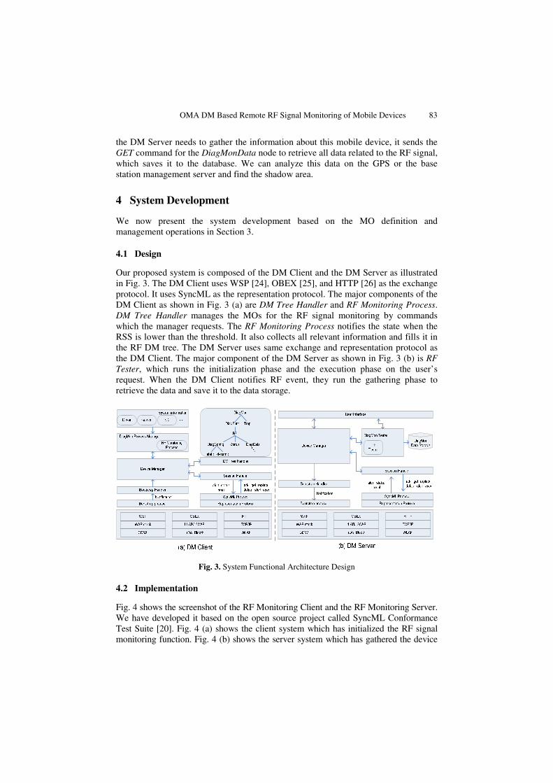
Our proposed system is composed of the DM Client and the DM Server as illustrated in Fig. 3. The DM Client uses WSP [24], OBEX [25], and HTTP [26] as the exchange protocol. It uses SyncML as the representation protocol. The major components of the DM Client as shown in Fig. 3 (a) are DM Tree Handler and RF Monitoring Process. DM Tree Handler manages the MOs for the RF signal monitoring by commands which the manager requests. The RF Monitoring Process notifies the state when the RSS is lower than the threshold. It also collects all relevant information and fills it in the RF DM tree. The DM Server uses same exchange and representation protocol as the DM Client. The major component of the DM Server as shown in Fig. 3 (b) is RF Tester, which runs the initialization phase and the execution phase on the user’s request. When the DM Client notifies RF event, they run the gathering phase to retrieve the data and save it to the data storage.
Fig. 3. System Functional Architecture Design
4.2 Implementation
Fig. 4 shows the screenshot of the RF Monitoring Client and the RF Monitoring Server. We have developed it based on the open source project called SyncML Conformance Test Suite [20]. Fig. 4 (a) shows the client system which has initialized the RF signal monitoring function. Fig. 4 (b) shows the server system which has gathered the device

84 J.-M. Kang et al.
information and the RF signal data from the mobile device 1. The server saves all monitoring data to the database and share with the analysis server. In the future, we will improve our system to show the shadow area by using and analyzing this data integrated with any other map application such as Google Maps [22].
Fig. 4. Screenshot of RF Signal Monitoring System
5 Performance Evaluation
In this section, we present the results of performance evaluation. We installed the RF Monitoring Server and the RF Monitoring Client on the desktop PC individually. They communicate through the Internet. In fact, the client must be installed on the mobile device, but we can perform the evaluation on the desktop because the focus of the evaluation is not the system overhead but the network overhead.
Fig. 5. Response time comparison of our proposed method and operation with separated commands
OMA DM Based Remote RF Signal Monitoring of Mobile Devices 85
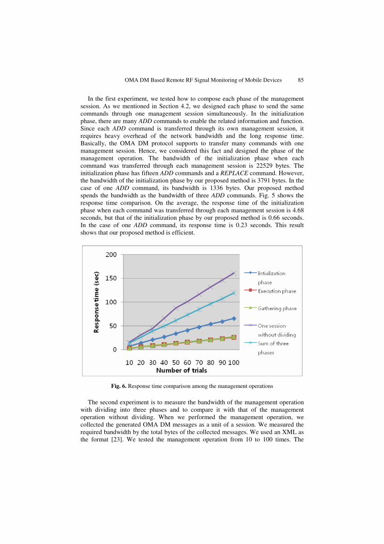
In the first experiment, we tested how to compose each phase of the management session. As we mentioned in Section 4.2, we designed each phase to send the same commands through one management session simultaneously. In the initialization phase, there are many ADD commands to enable the related information and function. Since each ADD command is transferred through its own management session, it requires heavy overhead of the network bandwidth and the long response time. Basically, the OMA DM protocol supports to transfer many commands with one management session. Hence, we considered this fact and designed the phase of the management operation. The bandwidth of the initialization phase when each command was transferred through each management session is 22529 bytes. The initialization phase has fifteen ADD commands and a REPLACE command. However, the bandwidth of the initialization phase by our proposed method is 3791 bytes. In the case of one ADD command, its bandwidth is 1336 bytes. Our proposed method spends the bandwidth as the bandwidth of three ADD commands. Fig. 5 shows the response time comparison. On the average, the response time of the initialization phase when each command was transferred through each management session is 4.68 seconds, but that of the initialization phase by our proposed method is 0.66 seconds. In the case of one ADD command, its response time is 0.23 seconds. This result shows that our proposed method is efficient.
Fig. 6. Response time comparison among the management operations
The second experiment is to measure the bandwidth of the management operation with dividing into three phases and to compare it with that of the management operation without dividing. When we performed the management operation, we collected the generated OMA DM messages as a unit of a session. We measured the required bandwidth by the total bytes of the collected messages. We used an XML as the format [23]. We tested the management operation from 10 to 100 times. The
86 J.-M. Kang et al.
bandwidth of the initialization phase is 3791 bytes, that of the execution phase is 2234 bytes, and that of the gathering phase is 1725 bytes. The management operation without dividing spends 7750 bytes. As shown in Fig. 6, we plotted the response time of each phase of the management operation based on the number of trials. On the average, the response time of the initialization phase is 0.66 seconds, that of the execution phase is 0.26 seconds, and that of the gathering phase is 0.28 seconds. The management operation without dividing in phases spends 1.61 seconds. As we have mentioned in Section 4.2, this result also shows that our proposed method for the design of the management operations, which divided the management operation into three phases, is efficient in the aspect of the bandwidth and the response time.
6 Concluding Remarks
The diagnostics and monitoring of the mobile device have become an important area in the mobile device management. In this paper, we proposed an efficient RF signal monitoring method of the mobile devices for the QoS improvement based on OMA DM. We defined the MOs for monitoring RF signal related data such as RSS. We also designed the management operation in three phases and presented that our proposed management operation was efficient in terms of the bandwidth and the response time by the results of the performance evaluation.
For future work, we plan to test the scalability of the DM server with many DM clients. We also plan to improve our system to self-diagnostic system using the concept of the autonomic computing [27].
References
1. Chakravorty, R., Ottevanger, H.: Architecture and Implementation of a Remote Management Framework for Dynamically Reconfigurable Devices. In: ICON 2002. Proc. of the 10th IEEE International Conference on Networks, Singapore, pp. 375–381 (August 2002)
2. Adwankar, S., Mohan, S., Vasudevan, V.: Universal Manager: Seamless Management of Enterprise Mobile and Non-Mobile Devices. In: MDM 2004. Proc. Of IEEE International Conference on Mobile Data Management, Berkeley, CA, USA, pp. 320–331 (January 2004)
3. OMA (Open Mobile Alliance), http://www.openmobilealliance.org/ 4. OMA DM (Device Management) Working Group,
http://www.openmobilealliance.org/tech/wg_committees/dm.html 5. OMA: OMA Device Management Standardized Objects (2007) 6. OMA: OMA Device Management Protocol (2007) 7. SyncML Forum: SyncML Device Management Protocol, http://www.syncml.org/ 8. OMA: OMA DM Device Description Framework, Version 1.2 (2007) 9. OMA: OMA Device Management Bootstrap (2007)
10. OMA: OMA Device Management Tree and Description (2007) 11. IETF: Uniform Resource Identifiers (URI), RFC 2396 (1998) 12. Stallings, W.: SNMP, SNMPv2, SNMPv3 and RMON 1 and 2, 3rd edn. Addison-Wesley,
Reading, MA (1999)

OMA DM Based Remote RF Signal Monitoring of Mobile Devices 87
13. Case, J., Fedor, M., Schoffstall, M., Davin, J.: A Simple Network Management Protocol (SNMP). RFC 1157, http://www.ietf.org/rfc/rfc1157.txt
14. OMA: DiagMon (Diagnostics and Monitoring) Working Group 15. OMA: DiagMon Requirement draft version 1.0 (June 2006) 16. van Thanh, D.D., Jonvik, T., Vanem, E., van Tran, D., Audestad, J.A.: The Device
Management Service. In: IN 2001. IEEE Intelligent Network Workshop 2001, Boston, MA, USA, pp. 199–211 (May 2001)
17. State, R., Festor, O., Zores, B.: An extensible agent toolkit for device management. In: NOMS 2004. IEEE/IFIP Network Operations and Management Symposium, Seoul, Korea, pp. 845–858 (April 2004)
18. Nokia, http://www.nokia.com/ 19. Nokia Forum, http://forum.nokia.com/ 20. SyncML Forum: SyncML Conformation Test Suite,
http://sourceforge.net/projects/oma-scts/ 21. Jiang, Y., Tham, C.K., Ko, C.C.: Challenges and approaches in providing QoS monitoring.
Int. J. Network Mgmt. 10, 323–334 (2000) 22. Google Maps Service, http://maps.google.com/ 23. W3C: Extensible Markup Language (XML), http://www.w3.org/XML/ 24. WAP: (Wireless Application Protocol) WSP (Wireless Session Protocol), WAP Forum,
http://www.wapforum.org/ 25. OBEX: (OBject EXchange), Infrared Data Association, http://www.irda.org/ 26. Fielding, R., Gettys, J., Mogul, J., Frystyk, H., Berners-Lee, T.: Hypertext Transfer
Protocol – HTTP/1.1, RFC 2068 (1997) 27. IBM Corporation: An architectural blueprint for autonomic computing. White Paper
(2003)


![Recent advances in industrial wireless sensor networks towards efficient management …sro.sussex.ac.uk/54129/1/07110295.pdf · 2019. 7. 3. · OMA Device Management (OMA DM) [2]](https://static.fdocuments.in/doc/165x107/603f6fb18dd0d319402e4df3/recent-advances-in-industrial-wireless-sensor-networks-towards-efficient-management.jpg)