
OKLAHOMA DEPARTMENT OF ENVIRONMENTAL … · Web viewStone flows through the preheater where it is...
144
OKLAHOMA DEPARTMENT OF ENVIRONMENTAL QUALITY AIR QUALITY DIVISION MEMORANDUM November 1, 2013 TO: Phillip Fielder, P.E., Permits and Engineering Group Manager, Air Quality Division THROUGH: Kendal Stegmann, Senior Environmental Manager, Compliance and Enforcement THROUGH: Phil Martin, P.E., Existing Source Permits Section THROUGH: Peer Review FROM: Ellis Fischer, P.E., Existing Source Permits Section SUBJECT: Evaluation of Permit Application No. 2008-284-C (M-1) (PSD) U. S. Lime Company – St. Clair Marble City Facility Section 14, T13N, R23E, Marble City, Sequoyah County Located 1 Mile Northwest of Marble City, Oklahoma on County Road 17 Latitude: 35.601 o N, Longitude 94.831 o W SECTION I. INTRODUCTON U. S. Lime Company – St. Clair (U.S. Lime) has applied for a construction permit for their Marble City crushed limestone and lime calcining facility (SIC 3274). That facility is currently operating under Permit No. 2008-284-TVR issued June 17, 2009. This application proposes the following changes:
Transcript of OKLAHOMA DEPARTMENT OF ENVIRONMENTAL … · Web viewStone flows through the preheater where it is...
OKLAHOMA DEPARTMENT OF ENVIRONMENTAL QUALITYAIR QUALITY DIVISION
MEMORANDUM November 1, 2013
TO: Phillip Fielder, P.E., Permits and Engineering Group Manager, Air Quality Division
THROUGH: Kendal Stegmann, Senior Environmental Manager, Complianceand Enforcement
THROUGH: Phil Martin, P.E., Existing Source Permits Section
THROUGH: Peer Review
FROM: Ellis Fischer, P.E., Existing Source Permits Section
SUBJECT: Evaluation of Permit Application No. 2008-284-C (M-1) (PSD)U. S. Lime Company – St. ClairMarble City FacilitySection 14, T13N, R23E, Marble City, Sequoyah CountyLocated 1 Mile Northwest of Marble City, Oklahoma on County Road 17Latitude: 35.601oN, Longitude 94.831oW
SECTION I. INTRODUCTON
U. S. Lime Company – St. Clair (U.S. Lime) has applied for a construction permit for their Marble City crushed limestone and lime calcining facility (SIC 3274). That facility is currently operating under Permit No. 2008-284-TVR issued June 17, 2009.
This application proposes the following changes:
Replacement of the Fuller kiln with a new energy efficient vertical parallel shaft regenerative kiln, solid fuel-fired with dust collector.
New secondary crusher, belts, feeders & other Crusher Department upgrades.
Revamped lime storage & loadout systems including new dust collectors.
Reduction of the SO2 emission limits for the kilns.
Reorganization of all permitted Emission Unit Groups (EUG) and emission points.
PERMIT MEMORANDUM 2008-284-C (M-1) (PSD) 2
Acronyms:
Emission Unit Group(s) (EUG or EUGs)Pulverized Limestone (PLS)Kennedy Van Saun Corporation (KVS)[This company was the builder of the existing 1964-vintage horizontal rotary kiln]Lime Kiln Dust (LKD)Calcium Carbonate (CaCO3)Lime (CaO)Dust Collector (DC)Loadout Spout (LS)Feed Bin (FB)
Note: Other acronyms are unique to applicant’s identification of EUG(s) and Point Identification (ID) as shown in the “description” part of tables.
SECTION II. FACILITY DESCRIPTION
This facility commenced operations in 1964 and is an existing major source by virtue of potential CO, NOx, PM10, and SO2 emissions in excess of 100 TPY. The facility is an integrated lime and high purity limestone production facility that mines limestone and processes it into a variety of lime products. The overall process involves crushing of mined limestone, which is nearly pure calcium carbonate (CaCO3), to produce chemical-grade limestone, lime (CaO), and hydrated lime products.
The proposed project will encompass modifications and modernization of several plant departments with the exception of the underground mine department, the fines department and the hydrator department. The existing Fuller kiln and several pieces of associated equipment will be replaced with a new vertical parallel shaft regenerative kiln and associated equipment. This change will affect the crushing department, solid fuel processing department and the lime handling/loading department.
Several existing operations will be equipped with new dust collectors (shown in the table below) resulting in emission reductions.

PERMIT MEMORANDUM 2008-284-C (M-1) (PSD) 3
Existing EU(Point)
New EU(Point) Description
EK-38(F-49)
3-LS-10(3-DC-10) Lime Bin #10 Loadout Spout
EK-133(P-6)
30-DS-1(30-DC-3)
Vertical Kiln LKD/Waste Bin – North(former KVS North LKD Silo)
EK-134(P-6)
30-DS-2(30-DC-3)
Vertical Kiln LKD/Waste Bin – South(former KVS South LKD Silo)
EK-113(F-61)
30-LS-1(30-DC-4)
Vertical Kiln LKD Loading Spout(former KVS LKD loadout)
Various 3-LS-31(3-DC-31)
Quicklime Railcar Loading(consolidation of several existing rail loading locations)
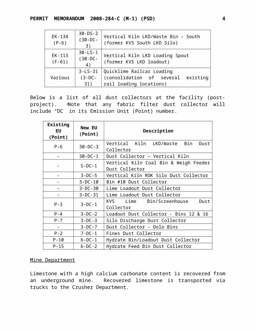
Below is a list of all dust collectors at the facility (post-project). Note that any fabric filter dust collector will include “DC” in its Emission Unit (Point) number.
Existing EU(Point)
New EU(Point) Description
P-6 30-DC-3 Vertical Kiln LKD/Waste Bin Dust Collector- 30-DC-1 Dust Collector – Vertical Kiln- 5-DC-1 Vertical Kiln Coal Bin & Weigh Feeder Dust Collector- 3-DC-5 Vertical Kiln ROK Silo Dust Collector- 3-DC-10 Bin #10 Dust Collector- 3-DC-30 Lime Loadout Dust Collector- 3-DC-31 Lime Loadout Dust Collector
P-3 3-DC-1 KVS Lime Bin/Screenhouse Dust CollectorP-4 3-DC-2 Loadout Dust Collector - Bins 12 & 16P-7 3-DC-3 Silo Discharge Dust Collector
- 3-DC-7 Dust Collector - Dolo BinsP-2 7-DC-1 Fines Dust CollectorP-10 6-DC-1 Hydrate Bin/Loadout Dust CollectorP-15 6-DC-2 Hydrate Feed Bin Dust Collector
Mine Department
Limestone with a high calcium carbonate content is recovered from an underground mine. Recovered limestone is transported via trucks to the Crusher Department.
Crusher Department
The Crusher Department reduces limestone containing various sizes using a two-stage crushing and screening process. Primary crushing is accomplished with a cast steel jaw crusher to reduce limestone to a size of approximately 9 inches or less. Primary crusher discharge is conveyed to the primary vibratory screen. The primary screen separates the limestone into three sizes: fines, middlings and oversize. Fines are conveyed to a fines stockpile for further processing at the Fines Department or stockpiled. Middlings are conveyed to the secondary screen for further classification. Oversized rock is conveyed to a surge stockpile, then to the secondary crusher for further crushing. The secondary crusher is a cone crusher that reduces oversize. Secondary
PERMIT MEMORANDUM 2008-284-C (M-1) (PSD) 4
crusher discharge is returned to the primary screen for classification as previously described.
Middlings from the primary screen are further classified by size at the secondary vibratory screen. The secondary screen produces various size kiln feed products. The products are stockpiled and subsequently conveyed to the Kiln Department for processing into quicklime. Fines from the secondary screen are stockpiled for shipping or transferred to the fines plant feed pile.
The Crushing Department has the potential to emit fugitive dust as a consequence of multiple stages of crushing, screening, conveying, truck haulage to load-out points and stockpiling. The fugitive dust at transfer points is further controlled by water spray bars mounted at the primary dump hopper and at several conveyor discharge points.
Fines Department
The Fines Department processes various size limestone by drying, grinding and sizing to several products. Limestone fines are conveyed from a fines stockpile to the Fines Building, where the fine material is stored in a fines feed bin for processing. In the roller mill system, the fines are conveyed from the feed silo to a roller mill with a natural gas-fired air heater and after grinding, air conveyed to a cyclone and then into product silos. This product is then loaded into bulk trucks and railcars via loading spouts under the product silos.
As a result, process emission at the Fines Department is limited to one point: the Fines Department baghouse, which serves the flash furnace, Raymond mill, product silos and truck loading spouts.
Kiln Department
The Kiln Department consists of two kilns; a KVS model rotary kiln was installed in 1964 with a wet scrubber, and a new parallel shaft regenerative kiln (Vertical Kiln) that is more efficient and produces lower emissions than a rotary kiln. The Vertical Kiln will be replacing the existing Fuller Kiln.
Sized limestone is conveyed from the secondary screen product stockpiles via vibratory feeders and belt conveyors to the KVS kiln feed bin. Stone flows through the preheater where it is pre-heated with gases exiting the rotary kiln. This kiln is fired with coal, petroleum coke and natural gas or some combination of these.
The sized limestone is calcined in the kiln system producing hard quicklime that must be cooled and often sized to meet market specifications. The entire KVS kiln system is under negative pressure from an induced draft fan located downstream of the cyclones and KVS wet scrubber which removes particulate matter from the exhaust gas stream. The particulate matter collected in the cyclones is partially calcined, which is transported to a silo where it is loaded into trucks for sale or disposition. Because coal is the dominant fuel, ash rings form at the front end of the KVS kiln, which must be periodically removed and disposed to prevent blockage of product flow.
PERMIT MEMORANDUM 2008-284-C (M-1) (PSD) 5
The new Vertical Kiln is fired with coal, petroleum coke, and/or natural gas with a quicklime production capacity of 210,240 TPY. A small natural gas fired inline heater will be located adjacent to the Vertical Kiln Bowl Mill to provide drying for the solid fuel. Exhaust gas from the new kiln will pass through a baghouse dust collector, an I.D. fan and through a stack to atmosphere. Due to baghouse design and kiln exhaust parameters, a small natural gas-fired inline heater is being permitted to be located before the baghouse. The inline heater is used during cold startup of the new kiln to prevent condensation on the bags and ensure proper operation of the baghouse. As such, emissions from the inline heater and the kiln’s natural gas-fired startup burner will be below the potential emissions that occur during normal kiln operation.
Quicklime from the Vertical Kiln will pass through new and existing lime storage and loadout facilities (see Lime Storage and Loadout Department). A new pneumatic conveying system will convey lime kiln dust (LKD) from the Vertical Kiln dust collector to the existing KVS LKD bins.
U.S. Lime is requesting a reduction of existing SO2 allowable emission rates from the kilns. The SO2 reduction would be from the existing allowable emission rate of 256.8 lbs/hr for the Fuller and KVS kilns combined, to 31 lbs/hr for the KVS and Vertical Kiln combined.
Lime Storage and Loadout Department
Lime from the kilns is conveyed to a screen where it is sized to meet customer requirements. A small amount of oversized material is ultimately crushed to a salable size. The quicklime is conveyed via bucket elevators, belt and screw conveyors to product silos according to product size and quality. Baghouses are strategically placed to collect dust throughout the quicklime handling system to keep all silos and open transfer points under negative pressure.
Two new quicklime silos will be provided to receive lime from the Vertical Kiln. Atop these silos will be an enclosed scalping screen, lime crusher and sizing screen. Lime will be transferred from the screens and from the new silos to the existing lime bins. Two new briquetters will be installed to agglomerate fines into briquettes which will be re-screened and distributed to storage bins with other quicklime.
A network of new feeders and conveyors will be installed under existing bins to consolidate quicklime loading activities. Dust collectors control particulate matter generated in the silo withdrawal systems and in the truck and rail loading processes.
Solid Fuels Processing Department
Solid fuels are received into open-air stockpiles, then moved by front-end loader to receiving hoppers where coal and petroleum coke are fed or blended. Each kiln has a bowl mill which grinds the coal/coke and an air classifier which is used to separate particles which are fine enough from those which must be returned to the mill for further grinding.
The KVS bowl mill is swept by an air stream heated with air from the kiln hood and the resultant
PERMIT MEMORANDUM 2008-284-C (M-1) (PSD) 6
air/fuel mixture is fed to the kiln through a single burner. This is referred to as a “direct fired” system.
Solid fuel for the Vertical Kiln is similarly prepared in a bowl mill which utilizes heat provided by a gas fired air heater to dry the fuel. This is an “indirect fired” system where the air/fuel mixture is carried to a cyclone and dust collector which discharge into a small pulverized solid fuel storage bin. Pulverized fuel then flows through a dosimeter which splits the required flow streams to fuel nozzles in the Vertical Kiln shafts.
The existing Fuller Lime Bin will be converted to a solid fuel storage bin serving the Vertical Kiln solid fuel processing equipment. A new weigh feeder will convey fuel from this bin to the bowl mill presently used for the Fuller kiln. A gas-fired air heater will be added to this bowl mill to provide drying heat for the fuel being processed.
Hydrator Department
The Hydrator Department receives quicklime for processing into hydrated lime Ca(OH)2. This is accomplished by application of water to quicklime in the hydrator, located inside the hydrator building. This is an exothermic process requiring no process heat.
Quicklime is transferred from the Kiln Department to the hydrator building via pneumatic pipeline (or pneumatic discharge trucks) from quicklime silos.
Except for quicklime transfer and bulk truck and rail car load-out, all processes in the Hydrator Department are enclosed inside the hydrator building. Quicklime is conveyed from the 25-ton feed bin to the hydrator which uses a multi-stage mixing process to add the correct amount of water to the quicklime to produce hydrated lime. The hydrated lime is then conveyed to a rotary impact mill and then to a Whizzer Classifier to remove oversize or caked material. Properly sized fine hydrate is pneumatically conveyed to hydrate product silos. Product loading is done by gravity loading into enclosed bulk trucks or rail cars from the product silos. A lesser portion of the product is bagged.
Emissions from the Hydrator Department come from the hydrator vent stack, connected to the hydrator unit, the quicklime feed bin vent and the hydrator baghouse, which serves the product silos and truck/rail loading spouts. At maximum capacity, the Hydrator Department could process approximately 16 tons of hydrate.
No changes are being made to equipment in this department.
SECTION III. EQUIPMENT
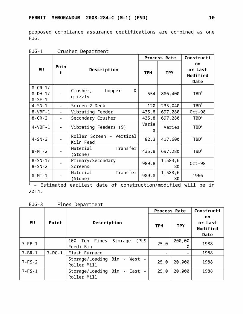
Emission units have been arranged into Emission Unit Groups (EUGs) as follows. Emission units that emit the same regulated air pollutants, trigger the same applicable requirements, share the same compliance demonstration methods, and share the same proposed compliance assurance certifications are combined as one EUG.
PERMIT MEMORANDUM 2008-284-C (M-1) (PSD) 7
EUG-1Crusher Department
EU Point DescriptionProcess Rate Construction
or LastModified DateTPH TPY
8-CR-1/8-DH-1/8-SF-1
- Crusher, hopper & grizzly 554 886,400 TBD1
4-SN-1 - Screen 2 Deck 120 235,040 TBD1 8-VBF-1 - Vibrating Feeder 435.8 697,280 Oct-988-CR-2 - Secondary Crusher 435.8 697,280 TBD1
4-VBF-1 - Vibrating Feeders (9) Varies Varies TBD1
4-SN-3 - Roller Screen – Vertical Kiln Feed 82.3 417,600 TBD1
8-MT-2 - Material Transfer (Stone) 435.8 697,280 TBD1
8-SN-1/8-SN-2 - Primary/Secondary Screens 989.8 1,583,680 Oct-98
8-MT-1 - Material Transfer (Stone) 989.8 1,583,680 19661 – Estimated earliest date of construction/modified will be in 2014.
EUG-3Fines Department
EU Point DescriptionProcess Rate Construction
or LastModified DateTPH TPY
7-FB-1 - 100 Ton Fines Storage (PLS Feed) Bin 25.0 200,000 19887-BR-1
7-DC-1
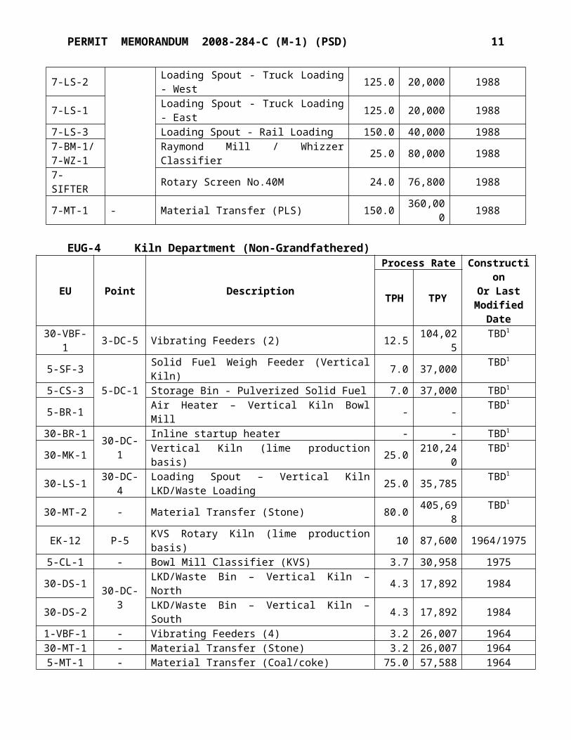
Flash Furnace - - 19887-FS-2 Storage/Loading Bin - West - Roller Mill 25.0 20,000 19887-FS-1 Storage/Loading Bin - East - Roller Mill 25.0 20,000 19887-LS-2 Loading Spout - Truck Loading - West 125.0 20,000 19887-LS-1 Loading Spout - Truck Loading - East 125.0 20,000 19887-LS-3 Loading Spout - Rail Loading 150.0 40,000 19887-BM-1/7-WZ-1 Raymond Mill / Whizzer Classifier 25.0 80,000 1988
7-SIFTER Rotary Screen No.40M 24.0 76,800 19887-MT-1 - Material Transfer (PLS) 150.0 360,000 1988
EUG-4 Kiln Department (Non-Grandfathered)
EU Point Description
Process Rate ConstructionOr Last
ModifiedDate
TPH TPY
30-VBF-1 3-DC-5 Vibrating Feeders (2) 12.5 104,025 TBD1
5-SF-35-DC-1
Solid Fuel Weigh Feeder (Vertical Kiln) 7.0 37,000 TBD1
5-CS-3 Storage Bin - Pulverized Solid Fuel 7.0 37,000 TBD1
5-BR-1 Air Heater – Vertical Kiln Bowl Mill - - TBD1
30-BR-1 30-DC-1 Inline startup heater - - TBD1
30-MK-1 Vertical Kiln (lime production basis) 25.0 210,240 TBD1
30-LS-1 30-DC-4 Loading Spout – Vertical Kiln LKD/Waste Loading 25.0 35,785 TBD1
30-MT-2 - Material Transfer (Stone) 80.0 405,698 TBD1
EK-12 P-5 KVS Rotary Kiln (lime production basis) 10 87,600 1964/1975
PERMIT MEMORANDUM 2008-284-C (M-1) (PSD) 8
EU Point Description Process Rate ConstructionOr Last
ModifiedTPH TPY
5-CL-1 - Bowl Mill Classifier (KVS) 3.7 30,958 197530-DS-1 30-DC-3 LKD/Waste Bin – Vertical Kiln – North 4.3 17,892 198430-DS-2 LKD/Waste Bin – Vertical Kiln – South 4.3 17,892 19841-VBF-1 - Vibrating Feeders (4) 3.2 26,007 196430-MT-1 - Material Transfer (Stone) 3.2 26,007 19645-MT-1 - Material Transfer (Coal/coke) 75.0 57,588 1964
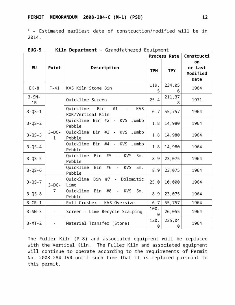
1 – Estimated earliest date of construction/modified will be in 2014.
EUG-5 Kiln Department - Grandfathered Equipment
EU Point DescriptionProcess Rate Construction
or LastModified
DateTPH TPY
EK-8 F-41 KVS Kiln Stone Bin 119.5 234,056 19643-SN-1B
3-DC-1
Quicklime Screen 25.4 211,378 19713-QS-1 Quicklime Bin #1 - KVS ROK/Vertical Kiln 6.7 55,757 19643-QS-2 Quicklime Bin #2 - KVS Jumbo Pebble 1.8 14,980 19643-QS-3 Quicklime Bin #3 - KVS Jumbo Pebble 1.8 14,980 19643-QS-4 Quicklime Bin #4 - KVS Jumbo Pebble 1.8 14,980 19643-QS-5 Quicklime Bin #5 - KVS Sm. Pebble 8.9 23,075 19643-QS-6 Quicklime Bin #6 - KVS Sm. Pebble 8.9 23,075 19643-QS-7 3-DC-7 Quicklime Bin #7 - Dolomitic Lime 25.0 10,000 19643-QS-8 Quicklime Bin #8 - KVS Sm. Pebble 8.9 23,075 19643-CR-1 - Roll Crusher - KVS Oversize 6.7 55,757 19643-SN-3 - Screen - Lime Recycle Scalping 100.0 26,055 19643-MT-2 - Material Transfer (Stone) 120.0 235,040 1964
The Fuller Kiln (P-8) and associated equipment will be replaced with the Vertical Kiln. The Fuller Kiln and associated equipment will continue to operate according to the requirements of Permit No. 2008-284-TVR until such time that it is replaced pursuant to this permit.
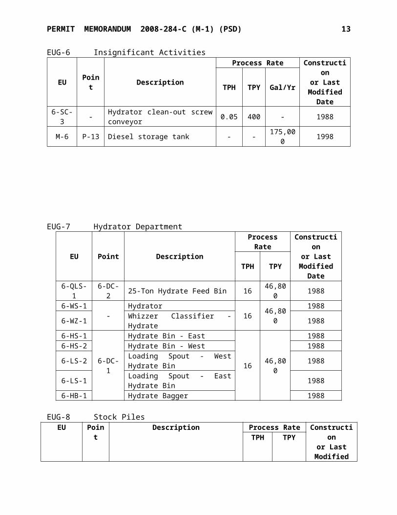
EUG-6Insignificant Activities
EU Point DescriptionProcess Rate Construction
or LastModified
DateTPH TPY Gal/Yr
6-SC-3 - Hydrator clean-out screw conveyor 0.05 400 - 1988M-6 P-13 Diesel storage tank - - 175,000 1998
EUG-7Hydrator Department
PERMIT MEMORANDUM 2008-284-C (M-1) (PSD) 9
EU Point Description
Process Rate Constructionor Last
ModifiedDate
TPH TPY
6-QLS-1 6-DC-2 25-Ton Hydrate Feed Bin 16 46,800 19886-WS-1 - Hydrator 16 46,800 19886-WZ-1 Whizzer Classifier - Hydrate 19886-HS-1
6-DC-1
Hydrate Bin - East
16 46,800
19886-HS-2 Hydrate Bin - West 19886-LS-2 Loading Spout - West Hydrate Bin 19886-LS-1 Loading Spout - East Hydrate Bin 19886-HB-1 Hydrate Bagger 1988
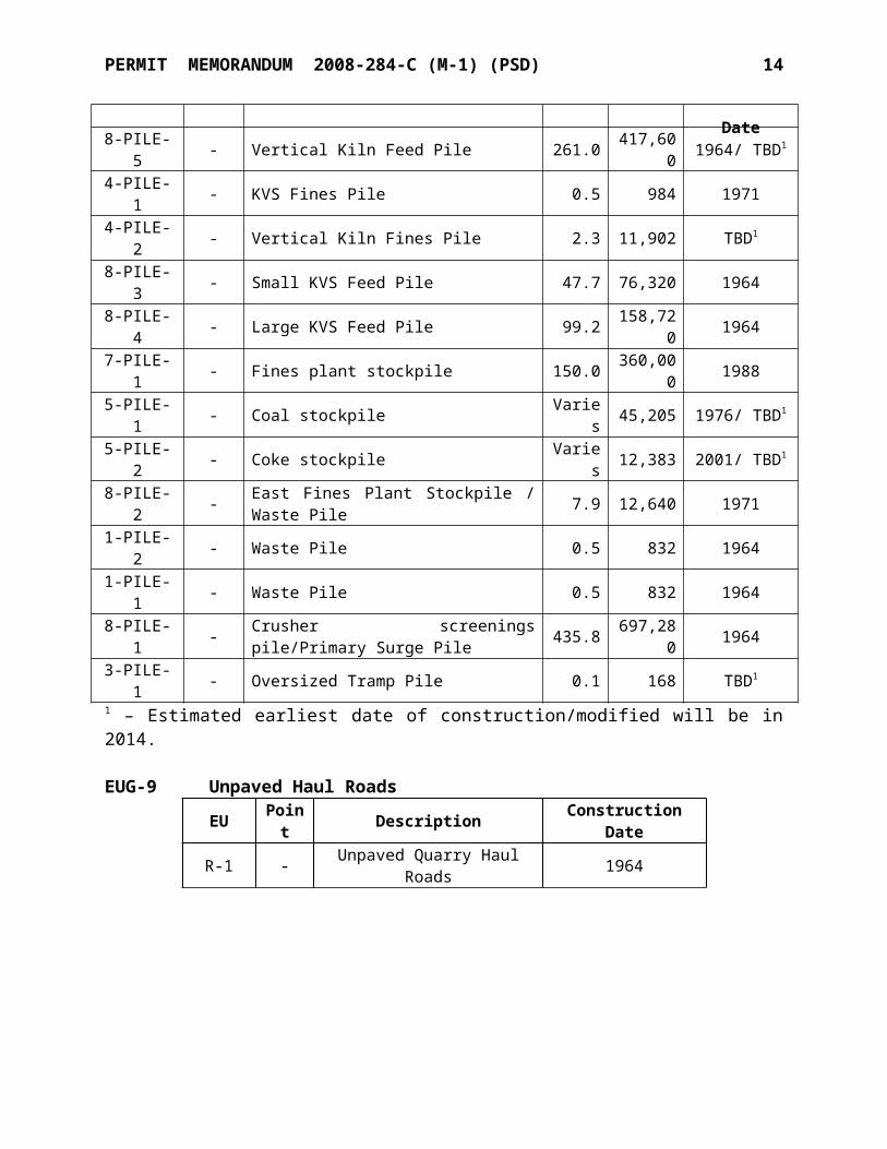
EUG-8Stock Piles
EU Point Description
Process Rate Constructionor Last
ModifiedDate
TPH TPY
8-PILE-5 - Vertical Kiln Feed Pile 261.0 417,600 1964/ TBD1 4-PILE-1 - KVS Fines Pile 0.5 984 19714-PILE-2 - Vertical Kiln Fines Pile 2.3 11,902 TBD1
8-PILE-3 - Small KVS Feed Pile 47.7 76,320 19648-PILE-4 - Large KVS Feed Pile 99.2 158,720 19647-PILE-1 - Fines plant stockpile 150.0 360,000 19885-PILE-1 - Coal stockpile Varies 45,205 1976/ TBD1 5-PILE-2 - Coke stockpile Varies 12,383 2001/ TBD1 8-PILE-2 - East Fines Plant Stockpile / Waste Pile 7.9 12,640 19711-PILE-2 - Waste Pile 0.5 832 19641-PILE-1 - Waste Pile 0.5 832 19648-PILE-1 - Crusher screenings pile/Primary Surge Pile 435.8 697,280 19643-PILE-1 - Oversized Tramp Pile 0.1 168 TBD1
1 – Estimated earliest date of construction/modified will be in 2014.
EUG-9 Unpaved Haul RoadsEU Point Description Construction DateR-1 - Unpaved Quarry Haul Roads 1964
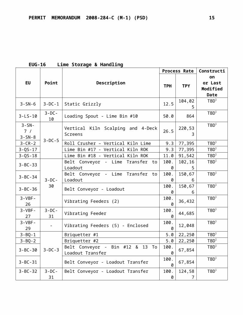
EUG-16 Lime Storage & Handling
PERMIT MEMORANDUM 2008-284-C (M-1) (PSD) 10
EU Point Description
Process Rate Constructionor Last
ModifiedDate
TPH TPY
3-SN-6 3-DC-1 Static Grizzly 12.5 104,025 TBD1
3-LS-10 3-DC-10 Loading Spout - Lime Bin #10 50.0 864 TBD1
3-SN-7 /3-SN-8
3-DC-5
Vertical Kiln Scalping and 4-Deck Screens 26.5 220,533 TBD1
3-CR-2 Roll Crusher – Vertical Kiln Lime 9.3 77,395 TBD1
3-QS-17 Lime Bin #17 - Vertical Kiln ROK 9.3 77,395 TBD1
3-QS-18 Lime Bin #18 - Vertical Kiln ROK 11.0 91,542 TBD1
3-BC-33
3-DC-30
Belt Conveyor - Lime Transfer to Loadout 100.0 102,165 TBD1
3-BC-34 Belt Conveyor - Lime Transfer to Loadout 100.0 150,676 TBD1
3-BC-36 Belt Conveyor - Loadout 100.0 150,676 TBD1
3-VBF-26 Vibrating Feeders (2) 100.0 36,432 TBD1
3-VBF-27 3-DC-31 Vibrating Feeder 100.0 44,685 TBD1
3-VBF-29 - Vibrating Feeders (5) - Enclosed 100.0 12,048 TBD1
3-BQ-1
3-DC-3
Briquetter #1 5.0 22,250 TBD1
3-BQ-2 Briquetter #2 5.0 22,250 TBD1
3-BC-30 Belt Conveyor - Bin #12 & 13 To Loadout Transfer 100.0 67,854 TBD1
3-BC-31 Belt Conveyor - Loadout Transfer 100.0 67,854 TBD1
3-BC-32 3-DC-31 Belt Conveyor - Loadout Transfer 100.0 124,587 TBD1
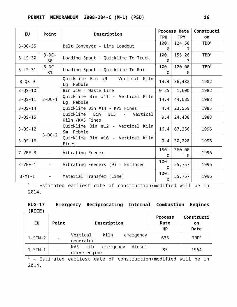
3-BC-35 Belt Conveyor - Lime Loadout 100.0 124,587 TBD1
3-LS-30 3-DC-30 Loading Spout - Quicklime To Truck 100.0 155,263 TBD1
3-LS-31 3-DC-31 Loading Spout - Quicklime To Rail 100.0 120,000 TBD1
3-QS-9
3-DC-1
Quicklime Bin #9 – Vertical Kiln Lg. Pebble 14.4 36,432 19823-QS-10 Bin #10 - Waste Lime 0.25 1,600 19823-QS-11 Quicklime Bin #11 - Vertical Kiln Lg. Pebble 14.4 44,685 19883-QS-14 Quicklime Bin #14 - KVS Fines 4.4 23,559 19853-QS-15 Quicklime Bin #15 - Vertical Kiln /KVS Fines 9.4 24,438 19883-QS-12 3-DC-2 Quicklime Bin #12 - Vertical Kiln Sm. Pebble 16.4 67,256 19963-QS-16 Quicklime Bin #16 - Vertical Kiln Fines 9.4 30,228 19967-VBF-3 - Vibrating Feeder 150.0 360,000 19963-VBF-1 - Vibrating Feeders (9) - Enclosed 100.0 55,757 19963-MT-1 - Material Transfer (Lime) 100.0 55,757 1996
1 – Estimated earliest date of construction/modified will be in 2014.
EUG-17 Emergency Reciprocating Internal Combustion Engines (RICE)
EU Point Description Process Rate ConstructionDateHP
1-STM-2 - Vertical kiln emergency generator 635 TBD1 1-STM-1 - KVS kiln emergency diesel drive engine 85 1964
1 – Estimated earliest date of construction/modified will be in 2014.
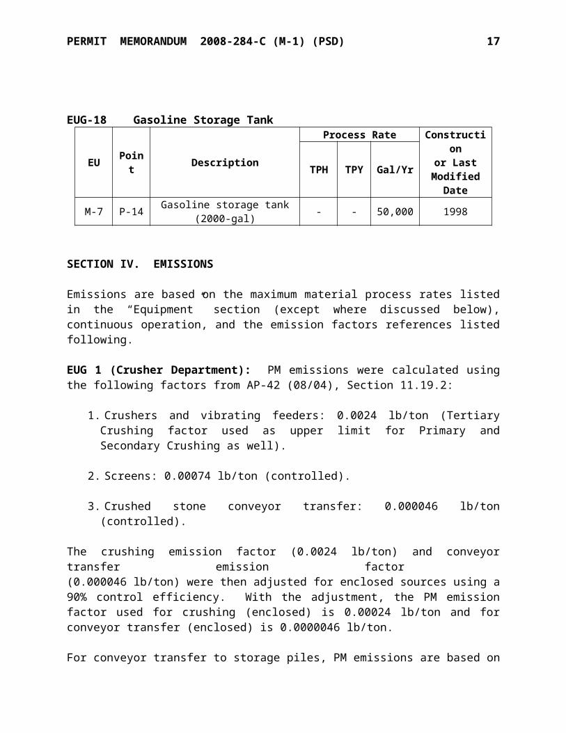
EUG-18 Gasoline Storage Tank
PERMIT MEMORANDUM 2008-284-C (M-1) (PSD) 11
EU Point Description
Process Rate Constructionor Last
ModifiedDate
TPH TPY Gal/Yr
M-7 P-14 Gasoline storage tank (2000-gal) - - 50,000 1998
SECTION IV. EMISSIONS
Emissions are based on the maximum material process rates listed in the “Equipment” section (except where discussed below), continuous operation, and the emission factors references listed following.
EUG 1 (Crusher Department): PM emissions were calculated using the following factors from AP-42 (08/04), Section 11.19.2:
1. Crushers and vibrating feeders: 0.0024 lb/ton (Tertiary Crushing factor used as upper limit for Primary and Secondary Crushing as well).
2. Screens: 0.00074 lb/ton (controlled).
3. Crushed stone conveyor transfer: 0.000046 lb/ton (controlled).
The crushing emission factor (0.0024 lb/ton) and conveyor transfer emission factor (0.000046 lb/ton) were then adjusted for enclosed sources using a 90% control efficiency. With the adjustment, the PM emission factor used for crushing (enclosed) is 0.00024 lb/ton and for conveyor transfer (enclosed) is 0.0000046 lb/ton.
For conveyor transfer to storage piles, PM emissions are based on the emission factors of AP-42 (11/06) Section 13.2.4.3, Equation (1) as follows:
E (lb/ton) = k (0.0032)(U/5)1.3/(M/2)1.4
with a value of 0.00207 lb/ton (controlled); where k is the particle size multiplier value of 0.35 for PM10; U is the mean wind speed value of 10.2 miles/hr; M is the moisture content value of 2.5% for crushed limestone (due to the use of water sprays).
EUG 3 (Fines Department): With the exception of material transfer operations, PM emissions from the remaining sources in EUG 3 are controlled by a dust collector. PM emissions from the Fines Dust Collector are based on the pre-1998 Subpart OOO grain loading limit (0.022 gr/dscf).
1. PM emissions from material transfer operations are based on AP-42 (08/04), Section 11.19.2: 0.000046 lb/ton (controlled conveyor transfer).
2. Combustion emissions from the 9.0 MMBTUH gas-fired dryer was based on AP-42 (7/98), Section 1.4.
PERMIT MEMORANDUM 2008-284-C (M-1) (PSD) 12
EUG 4 (Kiln Department): 1. KVS kiln emissions are based on the following:
a. PM10, PM2.5, CO emission factors: AP-42 (2/98), Section 11.17: i. 1.4 lb/ton (PM10) and 0.28 lb/ton (PM2.5) for coal-fired rotary kiln with venturi
scrubber (even though PM emission limitations will be based on Subchapter 19 allowables, expected emissions will continue to be calculated using AP-42 factors.)
ii. 1.5 lb/ton (CO) for coal-fired rotary kiln. The KVS rotary kiln is an existing unit and has no applicable CO emission standard in OAC regulation or in past permits.
b. NOx: emission factor is based on OAC 252: 100-33 limit of 0.7 lb/MMBtuc. SO2: Allowable emission rate for the KVS kiln is set at 9.3 lb/hr on a 30-day rolling
averaged. The wet scrubber is rated at 99.6% efficiency for PM control, and the system achieves
at least 97% SO2 emission reduction by virtue of lime dust present in the system and use of the wet scrubber.
2. Vertical Kiln emissions are based on the following:a. PM10: dust collector air flow and expected outlet grain loading
(0.015 gr/dscf)b. PM2.5: estimated by multiplying the PM10 emissions by a factor of 0.491. This factor
is the ratio of the particle size distribution data for PM2.5 (27 percent) and PM10 (55 percent) listed in AP-42 (08/04) Table 11.17-7 for the “Kiln with Fabric Filter” category. An additional safety factor of 85% was added to the Kiln PM2.5 emissions estimate due to the uncertainty of condensable PM and PM2.5 emission measurements.
c. CO: 4.22 lb/ton factor is the BACT limit.d. NOx: 2.20 lb/ton is based on vendor data with safety factor.e. SO2: 0.868 lb/ton is the BACT limit. Allowable emission rate is 21.7 lb/hr on a 30-
day rolling average.
3. Combustion emissions for the Bowl Mill air heater are based on AP-42 (7/98), Section 1.4.
4. Material transfer (stone) emissions are based on:a. AP-42 (08/04), Sections 11.19.2. The crushed stone conveyor transfer emission
factor 0.000046 lb/ton (controlled) was adjusted for enclosed sources using a 90% control efficiency. With the adjustment, the PM10 emission factor used for crushed stone conveyor transfer (enclosed) is 4.60E-06 lb/ton and for PM2.5 is 1.30 E-06 lb/ton. For uncontrolled stone transfer, 0.00110 lb/ton was used.
5. For stone transfer to a storage pile, AP-42 (11/06) Section 13.2.4.3, Equation (1) as follows:
E (lb/ton) = k (0.0032)(U/5)1.3/(M/2)1.4
PERMIT MEMORANDUM 2008-284-C (M-1) (PSD) 13
with a value of 0.0123 lb/ton (uncontrolled); where k is the particle size multiplier value of 0.35 for PM10 and 0.053 for PM2.5 ; U is the mean wind speed value of 10.2 miles/hr; M is the moisture content value of 0.7% (mean value for stone quarrying and processing of crushed limestone from Table 13.2.4-1).
6. For coal/coke transfer, AP-42 (11/06) Section 13.2.4.3, Equation (1) as follows:
E (lb/ton) = k (0.0032)(U/5)1.3/(M/2)1.4
with a value of 0.000909 lb/ton (uncontrolled); where k is the particle size multiplier value of 0.35 for PM10 and 0.053 for PM2.5; U is the mean wind speed value of 10.2 miles/hr; M is the moisture content value of 4.5% for coal and coke.
The remaining EUG 4 sources are controlled by dust collectors. PM emissions from the dust collectors are based on an outlet grain loading estimate (0.010 gr/dscf or 0.009 gr/dscf, except the new kiln dust collector which is 0.015 gr/dscf). PM2.5 emissions from dust collectors (except the kiln) are estimated to be the PM10 emissions divided by 10.2 (based on the average PM10/PM2.5 ratio for the AP-42 (08/04) Table 11.19.2-2 factors).
EUG 5 (Kiln Department - Grandfathered): 1. Dust collector emissions are based on a fabric filter outlet grain loading of 0.010
gr/dscf
2. Crushers and screens emissions are based on AP-42 Sections 11.17 (2/98) and 11.19.2 (08/04)
3. Material transfer emissions are based on the following:a. For crushed stone conveyor transfer, AP-42 (08/04), Section 11.19.2 as follows:
i. 0.000046 lb/ton (controlled) factor was used for the stone transfer from EU ID 4-SN-1 (formerly EK-18 in Permit No. 2008-284-TVR) controlled by water spray.
ii. Uncontrolled material transfer emissions are based on 0.0011 lb/ton factor.iii. For enclosed material transfer, PM emissions are based on 0.000046 lb/ton
(controlled) which was adjusted using a 90% control efficiency. With the adjustment, the PM emission factor is 0.0000046 lb/ton.
b. For material transfer to a storage pile, AP-42 (11/06) Section 13.2.4.3, Equation (1) as follows:
E (lb/ton) = k (0.0032)(U/5)1.3/(M/2)1.4
with a value of 0.0123 lb/ton (uncontrolled); where k is the particle size multiplier value of 0.35 for PM10; U is the mean wind speed value of 10.2 miles/hr; M is the moisture content value of 0.7% (mean value for stone quarrying and processing of crushed limestone from Table 13.2.4-1).
EUG-6 (Insignificant Activities): PM emissions for the hydrator clean-out conveyor are based
PERMIT MEMORANDUM 2008-284-C (M-1) (PSD) 14
on AP-42 (2/98), Section 11.17. VOC emissions from the tanks were calculated using TANKS 4.0.9d.
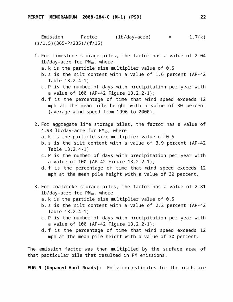
EUG 7 (Hydrator Department): Emissions from the hydrator are based on a discharge rate of 16 TPH and 46,800 TPY hydrated lime and the original manufacturer guarantee (0.24 lb/ton) referenced in Permit #89-003-O; emissions from the hydrate feed silo fabric filter are based on the Permit #89-003-O emission limit (1.13 lb/hr).EUG 8 (Stock Piles): AP-42 (1/95), Section 13.2.4. Estimates of particulate emissions from storage piles are based on Control of Open Fugitive Dust Sources1, where the emission factors are calculated as follows:
Emission Factor (lb/day-acre) = 1.7(k) (s/1.5)(365-P/235)/(f/15)
1. For limestone storage piles, the factor has a value of 2.04 lb/day-acre for PM10, where a. k is the particle size multiplier value of 0.5b. s is the silt content with a value of 1.6 percent (AP-42 Table 13.2.4-1)c. P is the number of days with precipitation per year with a value of 100 (AP-42 Figure
13.2.2-1); d. f is the percentage of time that wind speed exceeds 12 mph at the mean pile height
with a value of 30 percent (average wind speed from 1996 to 2000).
2. For aggregate lime storage piles, the factor has a value of 4.98 lb/day-acre for PM10, where a. k is the particle size multiplier value of 0.5b. s is the silt content with a value of 3.9 percent (AP-42 Table 13.2.4-1)c. P is the number of days with precipitation per year with a value of 100 (AP-42 Figure
13.2.2-1); d. f is the percentage of time that wind speed exceeds 12 mph at the mean pile height
with a value of 30 percent.
3. For coal/coke storage piles, the factor has a value of 2.81 lb/day-acre for PM10, where a. k is the particle size multiplier value of 0.5b. s is the silt content with a value of 2.2 percent (AP-42 Table 13.2.4-1)c. P is the number of days with precipitation per year with a value of 100 (AP-42 Figure
13.2.2-1); d. f is the percentage of time that wind speed exceeds 12 mph at the mean pile height
with a value of 30 percent.
The emission factor was then multiplied by the surface area of that particular pile that resulted in PM emissions.
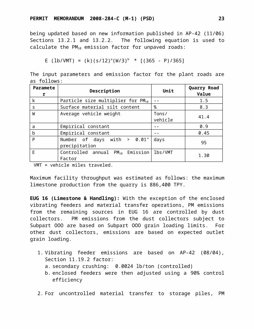
EUG 9 (Unpaved Haul Roads): Emission estimates for the roads are being updated based on new information published in AP-42 (11/06) Sections 13.2.1 and 13.2.2. The following equation is used to calculate the PM10 emission factor for unpaved roads:
1Control of Open Fugitive Dust Sources , U.S. EPA. EPA-450/3-88-008, 09/88.
PERMIT MEMORANDUM 2008-284-C (M-1) (PSD) 15
E (lb/VMT) = (k)(s/12)a(W/3)b * [(365 - P)/365]
The input parameters and emission factor for the plant roads are as follows:
Parameter Description Unit Quarry RoadValue
k Particle size multiplier for PM10 -- 1.5s Surface material silt content % 8.3W Average vehicle weight Tons/vehicle 41.4a Empirical constant -- 0.9b Empirical constant -- 0.45P Number of days with > 0.01" precipitation days 95E Controlled annual PM10 Emission Factor lbs/VMT 1.30VMT = vehicle miles traveled.
Maximum facility throughput was estimated as follows: the maximum limestone production from the quarry is 886,400 TPY.
EUG 16 (Limestone & Handling): With the exception of the enclosed vibrating feeders and material transfer operations, PM emissions from the remaining sources in EUG 16 are controlled by dust collectors. PM emissions from the dust collectors subject to Subpart OOO are based on Subpart OOO grain loading limits. For other dust collectors, emissions are based on expected outlet grain loading.
1. Vibrating feeder emissions are based on AP-42 (08/04), Section 11.19.2 factor:a. secondary crushing: 0.0024 lb/ton (controlled)b. enclosed feeders were then adjusted using a 90% control efficiency
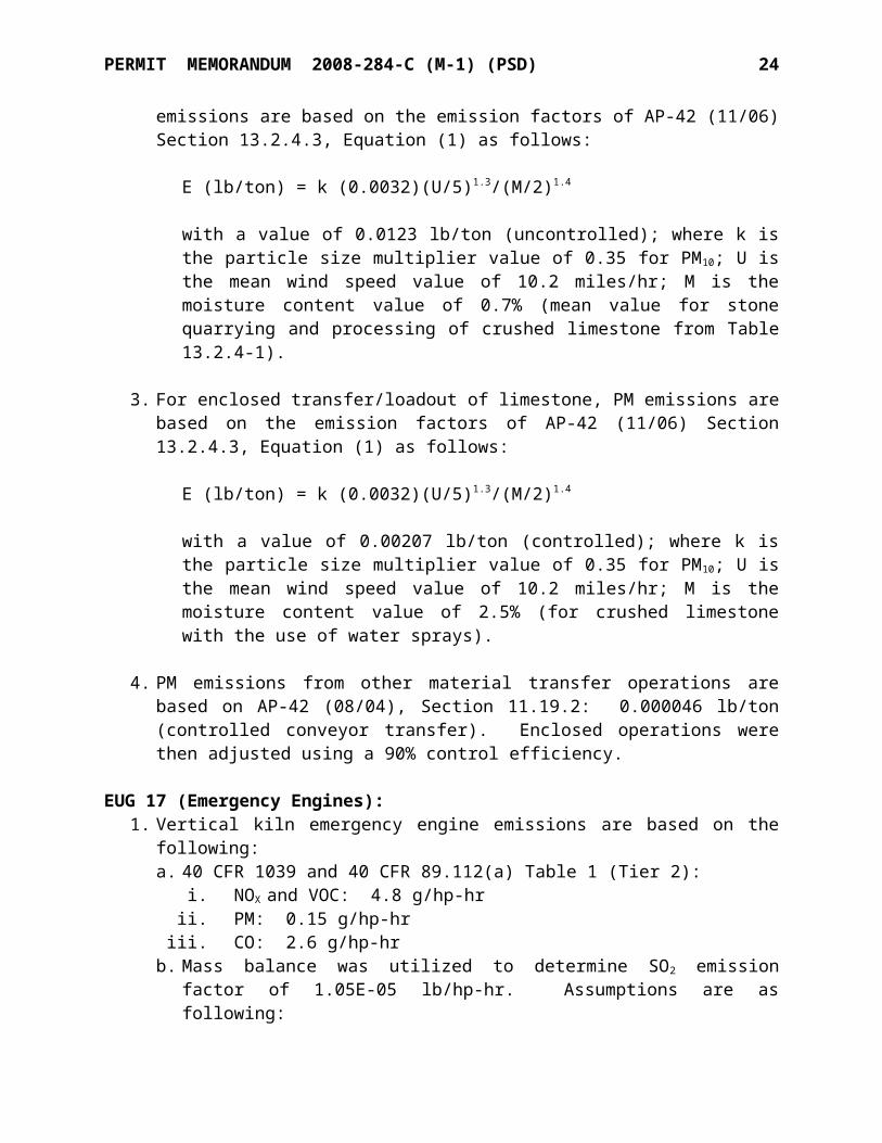
2. For uncontrolled material transfer to storage piles, PM emissions are based on the emission factors of AP-42 (11/06) Section 13.2.4.3, Equation (1) as follows:
E (lb/ton) = k (0.0032)(U/5)1.3/(M/2)1.4
with a value of 0.0123 lb/ton (uncontrolled); where k is the particle size multiplier value of 0.35 for PM10; U is the mean wind speed value of 10.2 miles/hr; M is the moisture content value of 0.7% (mean value for stone quarrying and processing of crushed limestone from Table 13.2.4-1).
3. For enclosed transfer/loadout of limestone, PM emissions are based on the emission factors of AP-42 (11/06) Section 13.2.4.3, Equation (1) as follows:
E (lb/ton) = k (0.0032)(U/5)1.3/(M/2)1.4
with a value of 0.00207 lb/ton (controlled); where k is the particle size multiplier value of 0.35 for PM10; U is the mean wind speed value of 10.2 miles/hr; M is the moisture content value of 2.5% (for crushed limestone with the use of water sprays).
4. PM emissions from other material transfer operations are based on AP-42 (08/04),
PERMIT MEMORANDUM 2008-284-C (M-1) (PSD) 16
Section 11.19.2: 0.000046 lb/ton (controlled conveyor transfer). Enclosed operations were then adjusted using a 90% control efficiency.
EUG 17 (Emergency Engines):1. Vertical kiln emergency engine emissions are based on the following:
a. 40 CFR 1039 and 40 CFR 89.112(a) Table 1 (Tier 2):i. NOX and VOC: 4.8 g/hp-hr
ii. PM: 0.15 g/hp-hriii. CO: 2.6 g/hp-hr
b. Mass balance was utilized to determine SO2 emission factor of 1.05E-05 lb/hp-hr. Assumptions are as following:
i. Heat content of diesel: 137,000 btu/galii. Density of diesel: 7.05 lb/gal
iii. 15 ppmw Sulfurc. GHG emissions are based on distillate fuel oil No. 2 emission factors from 40 CFR
Part 98, Subpart C (e.g., 73.96 kg CO2/MMBtu)
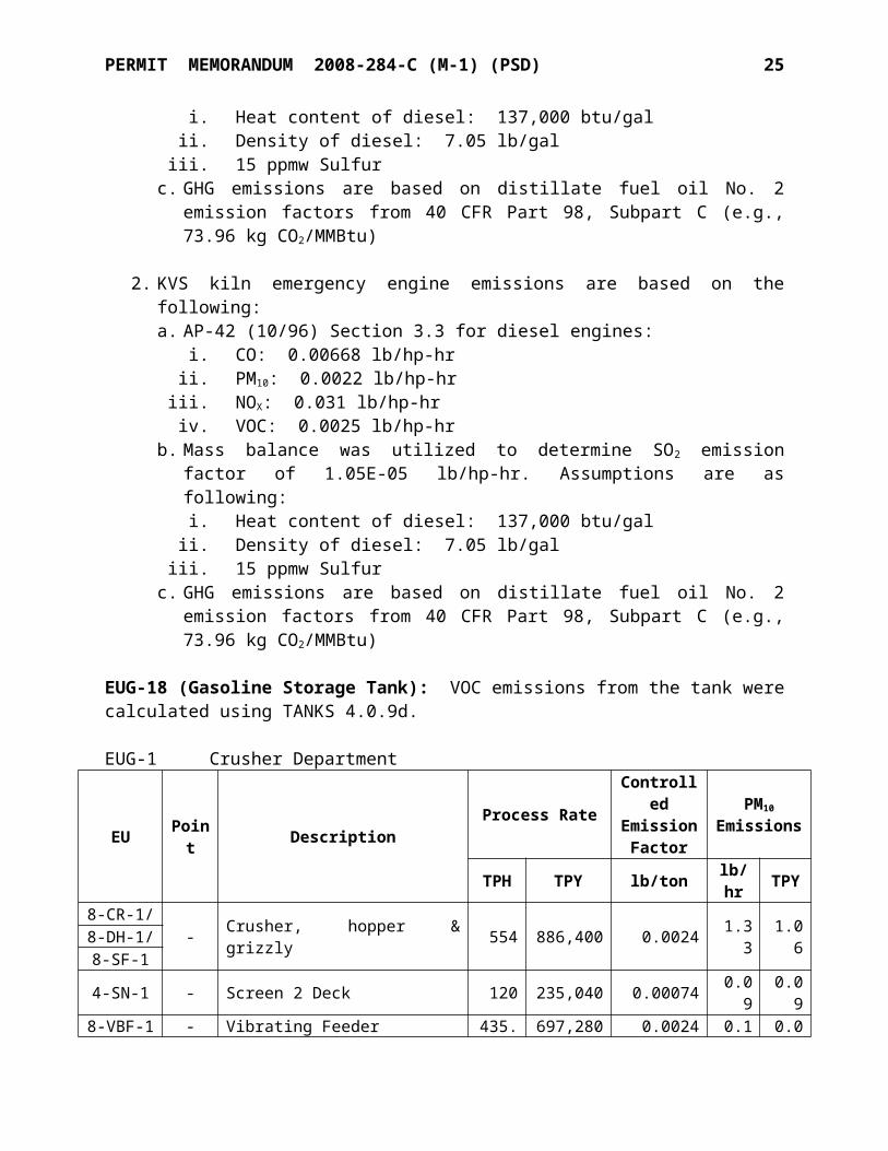
2. KVS kiln emergency engine emissions are based on the following:a. AP-42 (10/96) Section 3.3 for diesel engines:
i. CO: 0.00668 lb/hp-hrii. PM10: 0.0022 lb/hp-hr
iii. NOX: 0.031 lb/hp-hriv. VOC: 0.0025 lb/hp-hr
b. Mass balance was utilized to determine SO2 emission factor of 1.05E-05 lb/hp-hr. Assumptions are as following:
i. Heat content of diesel: 137,000 btu/galii. Density of diesel: 7.05 lb/gal
iii. 15 ppmw Sulfur c. GHG emissions are based on distillate fuel oil No. 2 emission factors from 40 CFR
Part 98, Subpart C (e.g., 73.96 kg CO2/MMBtu)
EUG-18 (Gasoline Storage Tank): VOC emissions from the tank were calculated using TANKS 4.0.9d.
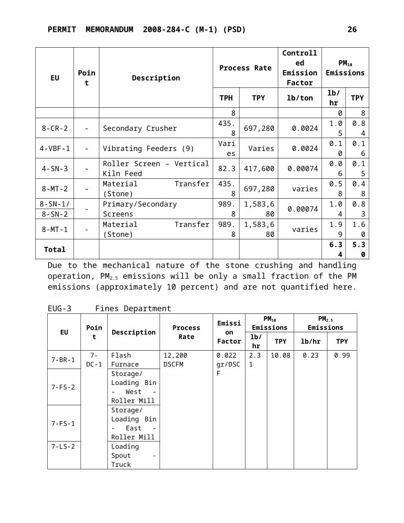
EUG-1Crusher Department
EU Point Description Process RateControlledEmission
Factor
PM10
Emissions
TPH TPY lb/ton lb/hr TPY8-CR-1/
- Crusher, hopper & grizzly 554 886,400 0.0024 1.33 1.068-DH-1/8-SF-14-SN-1 - Screen 2 Deck 120 235,040 0.00074 0.09 0.09
8-VBF-1 - Vibrating Feeder 435.8 697,280 0.0024 0.10 0.088-CR-2 - Secondary Crusher 435.8 697,280 0.0024 1.05 0.84
4-VBF-1 - Vibrating Feeders (9) Varies Varies 0.0024 0.10 0.164-SN-3 - Roller Screen – Vertical Kiln Feed 82.3 417,600 0.00074 0.06 0.15
PERMIT MEMORANDUM 2008-284-C (M-1) (PSD) 17
EU Point Description Process RateControlledEmission
Factor
PM10
Emissions
TPH TPY lb/ton lb/hr TPY8-MT-2 - Material Transfer (Stone) 435.8 697,280 varies 0.58 0.488-SN-1/ - Primary/Secondary Screens 989.8 1,583,680 0.00074 1.04 0.838-SN-28-MT-1 - Material Transfer (Stone) 989.8 1,583,680 varies 1.99 1.60Total 6.34 5.30Due to the mechanical nature of the stone crushing and handling operation, PM2.5 emissions will be only a small fraction of the PM emissions (approximately 10 percent) and are not quantified here.
EUG-3Fines Department
EU Point Description Process RateEmissio
nFactor
PM10
EmissionsPM2.5 Emissions
lb/hr TPY lb/hr TPY7-BR-1
7-DC-1
Flash Furnace
12,200 DSCFM 0.022 gr/DSCF 2.31 10.08 0.23 0.99
7-FS-2Storage/Loading Bin - West - Roller Mill
7-FS-1Storage/Loading Bin - East - Roller Mill
7-LS-2Loading Spout - Truck Loading - West
7-LS-1Loading Spout - Truck Loading - East
7-LS-3 Loading Spout - Rail Loading
7-BM-1/7-WZ-1
Raymond Mill / Whizzer Classifier
7-SIFTER
Rotary Screen No. 40M
7-FB-1 -100 Ton Fines Storage (PLS Feed) Bin
25 TPH
200,000 TPY
0.0014 lb/ton 0.04 0.14 0.004 0.014
7-MT-1 - Material Transfer (PLS)
150 TPH
360,000 TPY
4.60E-05 lb/ton 0.01 0.02 0.004 0.005
Total 2.36 10.24 0.23 1.01
EUG-3 Fines Department - continued
EU Description Heat InputMMBtu/hr Pollutant Emission Factor
lb/MMscfEmissions
lb/hr TPY
7-BR-1 Flash Furnace 9
NOx 100 0.90 3.95CO 84 0.76 3.32VOC 5.5 0.05 0.22SO2 0.6 0.01 0.03
PERMIT MEMORANDUM 2008-284-C (M-1) (PSD) 18
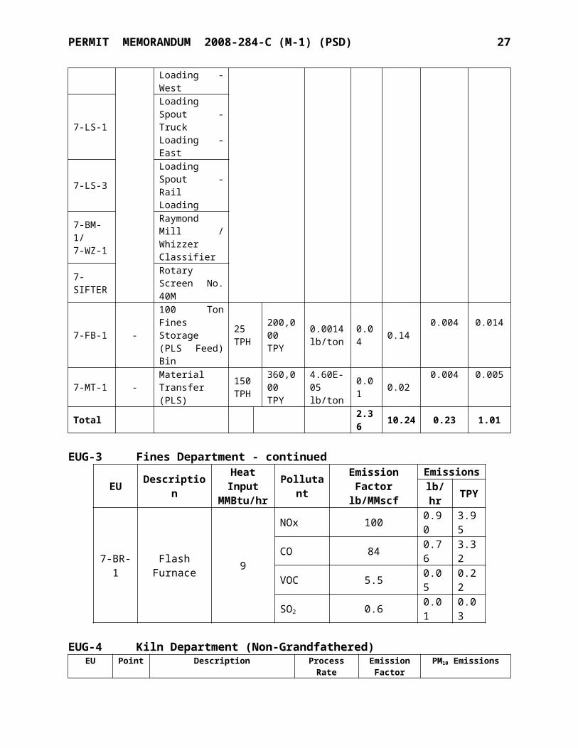
EUG-4 Kiln Department (Non-Grandfathered)
EU Point DescriptionProcess Rate Emission
Factor
PM10 EmissionsTPH TPY lb/hr TPY
30-VBF-1 3-DC-5 Vibrating Feeders (2) 9,000 DSCFM 0.010
gr/DSCF
Emissions from 3-DC-5are included in EUG 16
5-SF-3 5-DC-1Solid Fuel Weigh Feeder (Vertical Kiln) 13,500
DSCFM0.009 gr/DSCF 1.05 4.57
5-CS-3 Storage Bin - Pulverized Solid Fuel5-BR-1 5-DC-1 Air Heater – Vertical Kiln Bowl Mill - - 7.6 lb/MMscf 0.04 0.18
30-BR-1 30-DC-1 Inline startup heater 53,133
DSCFM0.015 gr/DSCF 6.84 29.93
30-MK-1 30-DC-1 Vertical Kiln
30-LS-1 30-DC-4
Loading Spout – Vertical Kiln LKD/Waste Loading 675 DSCFM 0.010
gr/DSCF 0.06 0.26
30-MT-2 - Material Transfer (Stone) 80 405,698
4.60E-06 lb/ton 0.001 0.002
EK-12/5-CL-1 P-5 KVS Rotary Kiln with Bowl Mill
classifier* 10 87,600 1.40 lb/ton 14.00 61.32
30-DS-1 30-DC-3 LKD/Waste Bin - Vertical Kiln - North
1,350 DSCFM 0.010 gr/DSCF 0.12 0.51
30-DS-2 30-DC-3 LKD/Waste Bin - Vertical Kiln - South
1-VBF-1 - Vibrating Feeders (4) 3.2 26,007 0.0024 lb/ton 0.03 0.1230-MT-1 - Material Transfer (Stone) 3.2 26,007 varies 0.01 0.06
5-MT-1 - Material Transfer (Coal/coke) 75.0 57,588 9.09E-04 lb/ton 1.04 0.26
Total 23.19 97.22* For informational purposes only; PM emissions limitations are based on the standards of OAC 252:100-19.
EUG-4 Kiln Department (Non-Grandfathered) - continued
EU Point Description Heat InputMMBtu/hr
Pollutant
EmissionFactor
lb/MMscf
Emissions
lb/hr
TPY
5-BR-1
5-DC-1
Air Heater - Vertical Kiln Bowl Mill
5
NOx 100 0.50 2.19CO 84 0.42 1.84VOC 5.5 0.03 0.14SO2 0.6 0.01 0.05
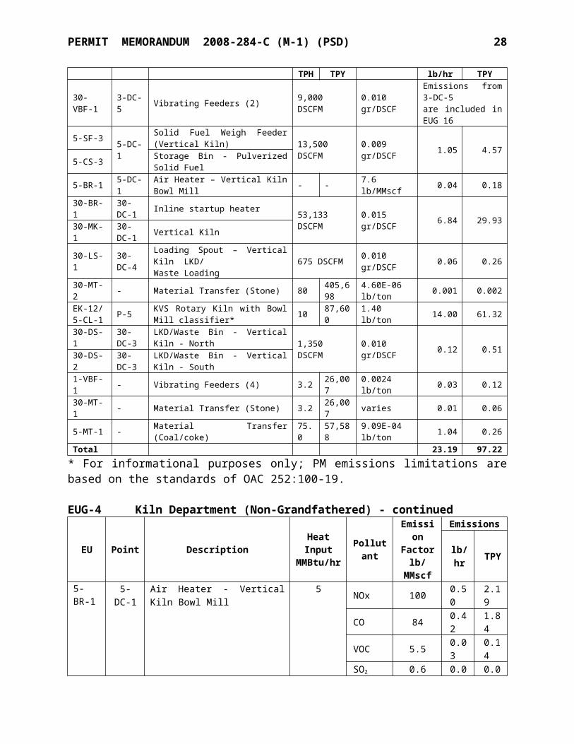
EU Point Description PollutantEmission
Factorlb/ton
Emissions
lb/hr TPY
EK-12 P-5 KVS Rotary KilnNOx 5.53 55.30 242.21CO* 1.5 15.00 65.70SO2 - 9.3 40.7
30-MK-1 30-DC-1 Vertical KilnSO2 0.868 21.7 91.2NOx 2.20 55.00 231.26CO 4.22 105.50 443.61
PERMIT MEMORANDUM 2008-284-C (M-1) (PSD) 19
* The KVS rotary kiln is an existing unit and has no applicable CO emission standard in OAC regulation or in past permits.
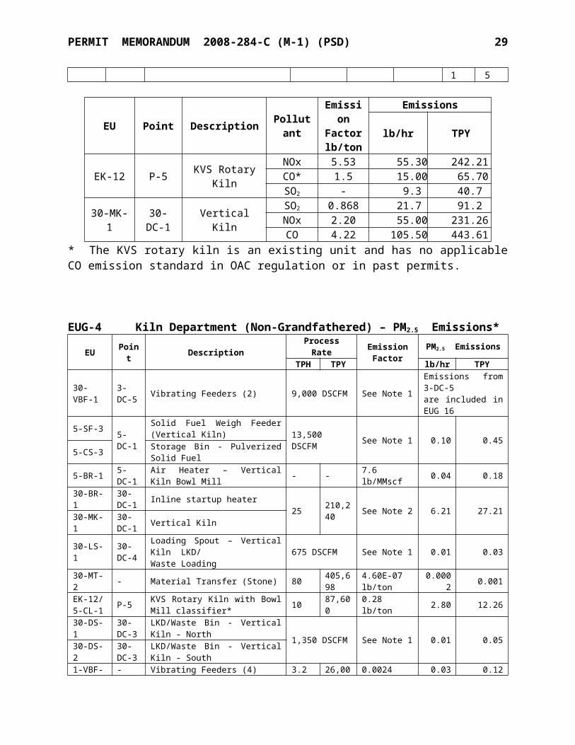
EUG-4 Kiln Department (Non-Grandfathered) – PM2.5 Emissions*EU Point Description Process Rate Emission
FactorPM2.5 Emissions
TPH TPY lb/hr TPY
30-VBF-1
3-DC-5 Vibrating Feeders (2) 9,000 DSCFM See Note 1
Emissions from 3-DC-5are included in EUG 16
5-SF-3 5-DC-1
Solid Fuel Weigh Feeder (Vertical Kiln) 13,500 DSCFM See Note 1 0.10 0.45
5-CS-3 Storage Bin - Pulverized Solid Fuel
5-BR-1 5-DC-1 Air Heater – Vertical Kiln Bowl Mill - - 7.6 lb/MMscf 0.04 0.18
30-BR-1 30-DC-1 Inline startup heater
25 210,240 See Note 2 6.21 27.21
30-MK-1 30-DC-1 Vertical Kiln
30-LS-1 30-DC-4
Loading Spout – Vertical Kiln LKD/Waste Loading 675 DSCFM See Note 1 0.01 0.03
30-MT-2 - Material Transfer (Stone) 80 405,698
4.60E-07 lb/ton 0.0002 0.001
EK-12/5-CL-1 P-5 KVS Rotary Kiln with Bowl Mill
classifier* 10 87,600 0.28 lb/ton 2.80 12.26
30-DS-1 30-DC-3
LKD/Waste Bin - Vertical Kiln - North 1,350 DSCFM See Note 1 0.01 0.05
30-DS-2 30-DC-3
LKD/Waste Bin - Vertical Kiln - South
1-VBF-1 - Vibrating Feeders (4) 3.2 26,007 0.0024 lb/ton 0.03 0.1230-MT-1 - Material Transfer (Stone) 3.2 26,007 varies 0.001 0.01
5-MT-1 - Material Transfer (Coal/coke) 75.0 57,588 1.38E-04 lb/ton 0.16 0.04
Total 9.36 40.35* For informational purposes only; PM emissions limitations are based on the standards of OAC 252:100-19.
Note 1: PM2.5 emissions from dust collectors and other non-combustion dust sources are estimated by dividing the PM10 values by 10.2, a PM10/PM2.5 ratio derived from AP-42 (08/04), Table 11.19.2-2.
Note 2: PM2.5 emissions from the Vertical Kiln are estimated by multiplying the PM10 values by 0.491, a PM2.5 /PM10 ratio derived from AP-42 Table (08/04), 11.17-7. An additional safety factor of 85 percent was then added due to the uncertainty of PM2.5 emission measurements.
EUG-5Kiln Department - Grandfathered
EU Point Description Process Rate Emission Factor PM10 Emissions
TPH TPY lb/ton lb/hr TPY
EK-8 F-41 KVS Kiln Stone Bin 119.5
234,056 0.0014 0.04 0.14
3-SN-1B
3-DC-1 Quicklime Screen 14,900 DSCFM 0.010
gr/DSCFEmissions from 3-DC-1are included in EUG-3-QS-1 Quicklime Bin #1 - KVS
PERMIT MEMORANDUM 2008-284-C (M-1) (PSD) 20
ROK/Vertical Kiln
16
3-QS-2 Quicklime Bin #2 - KVS Jumbo Pebble
3-QS-3 Quicklime Bin #3 - KVS Jumbo Pebble
3-QS-4 Quicklime Bin #4 - KVS Jumbo Pebble
3-QS-5 Quicklime Bin #5 - KVS Sm. Pebble
3-QS-6 Quicklime Bin #6 - KVS Sm. Pebble
3-QS-7 3-DC-7
Quicklime Bin #7 - Dolomitic Lime 2,250 DSCFM 0.010
gr/DSCF 0.20 0.853-QS-8 Quicklime Bin #8 - KVS Sm.
Pebble3-CR-1 - Roll Crusher - KVS Oversize 6.7 55,757 0.0024 0.002 0.01
3-SN-3 - Screen - Lime Recycle Scalping 100 26,055 0.072 0.72 0.09
3-MT-2 - Material Transfer (Stone) 120 235,040 varies 0.03 0.07
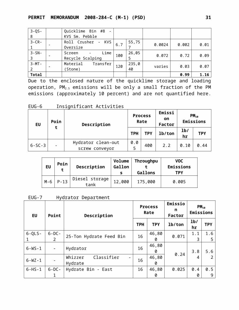
Total 0.99 1.16Due to the enclosed nature of the quicklime storage and loading operation, PM2.5 emissions will be only a small fraction of the PM emissions (approximately 10 percent) and are not quantified here.
EUG-6Insignificant Activities
EU Point Description Process Rate EmissionFactor PM10 Emissions
TPH TPY lb/ton lb/hr TPY
6-SC-3 - Hydrator clean-out screw conveyor 0.05 400 2.2 0.10 0.44
EU Point Description VolumeGallons
ThroughputGallons
VOC EmissionsTPY
M-6 P-13 Diesel storage tank 12,000 175,000 0.005
EUG-7Hydrator Department
EU Point Description Process Rate EmissionFactor
PM10
EmissionsTPH TPY lb/ton lb/hr TPY
6-QLS-1 6-DC-2 25-Ton Hydrate Feed Bin 16 46,800 0.071 1.13 1.656-WS-1 - Hydrator 16 46,800 0.24 3.84 5.626-WZ-1 - Whizzer Classifier - Hydrate 16 46,8006-HS-1 6-DC-1 Hydrate Bin - East
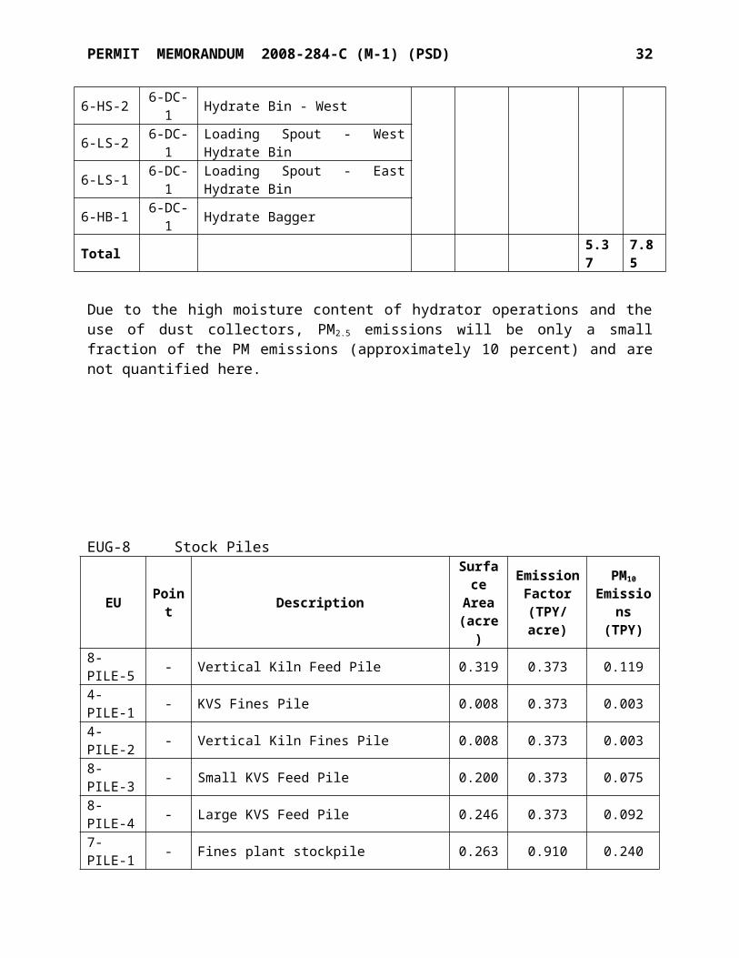
16 46,800 0.025 0.40 0.596-HS-2 6-DC-1 Hydrate Bin - West6-LS-2 6-DC-1 Loading Spout - West Hydrate Bin6-LS-1 6-DC-1 Loading Spout - East Hydrate Bin6-HB-1 6-DC-1 Hydrate BaggerTotal 5.37 7.85
PERMIT MEMORANDUM 2008-284-C (M-1) (PSD) 21
Due to the high moisture content of hydrator operations and the use of dust collectors, PM 2.5
emissions will be only a small fraction of the PM emissions (approximately 10 percent) and are not quantified here.
EUG-8Stock Piles
EU Point DescriptionSurface
Area(acre)
EmissionFactor
(TPY/acre)
PM10
Emissions(TPY)
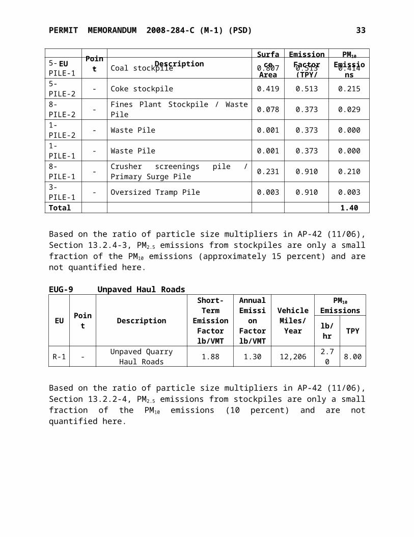
8-PILE-5 - Vertical Kiln Feed Pile 0.319 0.373 0.1194-PILE-1 - KVS Fines Pile 0.008 0.373 0.0034-PILE-2 - Vertical Kiln Fines Pile 0.008 0.373 0.0038-PILE-3 - Small KVS Feed Pile 0.200 0.373 0.0758-PILE-4 - Large KVS Feed Pile 0.246 0.373 0.0927-PILE-1 - Fines plant stockpile 0.263 0.910 0.2405-PILE-1 - Coal stockpile 0.807 0.513 0.4145-PILE-2 - Coke stockpile 0.419 0.513 0.2158-PILE-2 - Fines Plant Stockpile / Waste Pile 0.078 0.373 0.0291-PILE-2 - Waste Pile 0.001 0.373 0.0001-PILE-1 - Waste Pile 0.001 0.373 0.0008-PILE-1 - Crusher screenings pile / Primary Surge Pile 0.231 0.910 0.2103-PILE-1 - Oversized Tramp Pile 0.003 0.910 0.003Total 1.40
Based on the ratio of particle size multipliers in AP-42 (11/06), Section 13.2.4-3, PM2.5 emissions from stockpiles are only a small fraction of the PM10 emissions (approximately 15 percent) and are not quantified here.
EUG-9 Unpaved Haul Roads
EU Point Description
Short-TermEmission
Factorlb/VMT
AnnualEmission
Factorlb/VMT
VehicleMiles/Year
PM10
Emissions
lb/hr TPY
R-1 - Unpaved Quarry Haul Roads 1.88 1.30 12,206 2.70 8.00
Based on the ratio of particle size multipliers in AP-42 (11/06), Section 13.2.2-4, PM2.5 emissions from stockpiles are only a small fraction of the PM10 emissions (10 percent) and are not quantified here.
PERMIT MEMORANDUM 2008-284-C (M-1) (PSD) 22
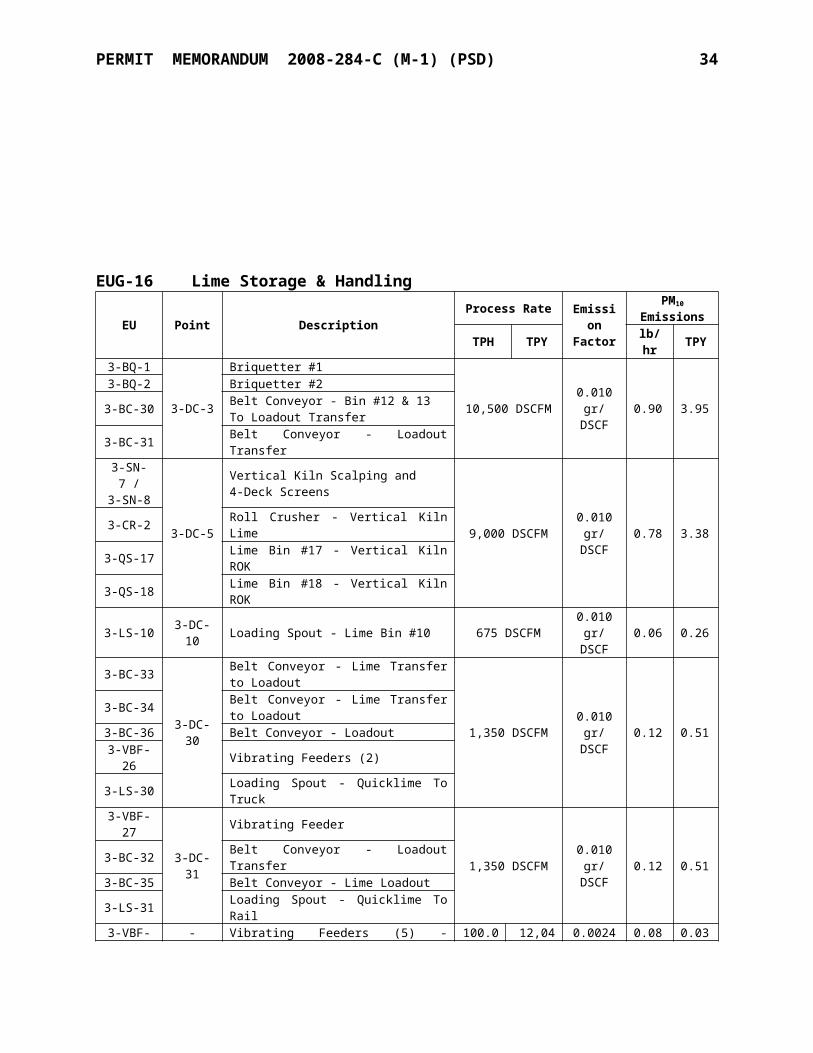
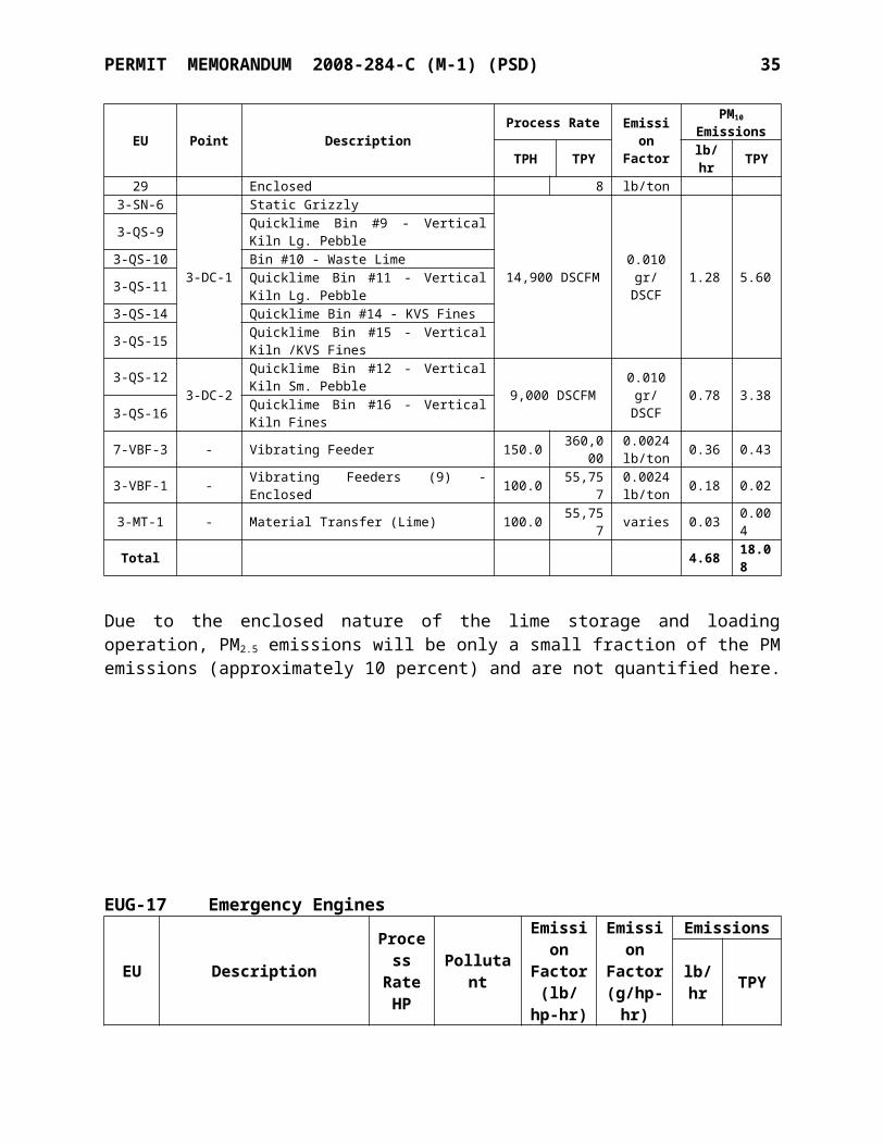
EUG-16 Lime Storage & Handling
EU Point Description Process Rate EmissionFactor
PM10
EmissionsTPH TPY lb/hr TPY
3-BQ-1
3-DC-3
Briquetter #1
10,500 DSCFM 0.010gr/DSCF 0.90 3.95
3-BQ-2 Briquetter #2
3-BC-30 Belt Conveyor - Bin #12 & 13To Loadout Transfer
3-BC-31 Belt Conveyor - Loadout Transfer 3-SN-7 /3-SN-8
3-DC-5
Vertical Kiln Scalping and4-Deck Screens
9,000 DSCFM 0.010gr/DSCF 0.78 3.383-CR-2 Roll Crusher - Vertical Kiln Lime
3-QS-17 Lime Bin #17 - Vertical Kiln ROK 3-QS-18 Lime Bin #18 - Vertical Kiln ROK
3-LS-10 3-DC-10 Loading Spout - Lime Bin #10 675 DSCFM 0.010gr/DSCF 0.06 0.26
3-BC-33
3-DC-30
Belt Conveyor - Lime Transfer to Loadout
1,350 DSCFM 0.010gr/DSCF 0.12 0.51
3-BC-34 Belt Conveyor - Lime Transfer to Loadout 3-BC-36 Belt Conveyor - Loadout
3-VBF-26 Vibrating Feeders (2)3-LS-30 Loading Spout - Quicklime To Truck
3-VBF-27
3-DC-31
Vibrating Feeder
1,350 DSCFM 0.010gr/DSCF 0.12 0.513-BC-32 Belt Conveyor - Loadout Transfer
3-BC-35 Belt Conveyor - Lime Loadout 3-LS-31 Loading Spout - Quicklime To Rail
3-VBF-29 - Vibrating Feeders (5) - Enclosed 100.0 12,048 0.0024lb/ton 0.08 0.03
3-SN-6
3-DC-1
Static Grizzly
14,900 DSCFM 0.010gr/DSCF 1.28 5.60
3-QS-9 Quicklime Bin #9 - Vertical Kiln Lg. Pebble3-QS-10 Bin #10 - Waste Lime
3-QS-11 Quicklime Bin #11 - Vertical Kiln Lg. Pebble
3-QS-14 Quicklime Bin #14 - KVS Fines
3-QS-15 Quicklime Bin #15 - Vertical Kiln /KVS Fines
3-QS-12 3-DC-2Quicklime Bin #12 - Vertical Kiln Sm. Pebble 9,000 DSCFM 0.010
gr/DSCF 0.78 3.383-QS-16 Quicklime Bin #16 - Vertical Kiln Fines
7-VBF-3 - Vibrating Feeder 150.0 360,000 0.0024lb/ton 0.36 0.43
3-VBF-1 - Vibrating Feeders (9) - Enclosed 100.0 55,757 0.0024lb/ton 0.18 0.02
3-MT-1 - Material Transfer (Lime) 100.0 55,757 varies 0.03 0.004Total 4.68 18.08
PERMIT MEMORANDUM 2008-284-C (M-1) (PSD) 23
Due to the enclosed nature of the lime storage and loading operation, PM2.5 emissions will be only a small fraction of the PM emissions (approximately 10 percent) and are not quantified here.
EUG-17 Emergency Engines
EU Description
Process
RateHP
Pollutant
Emission
Factor(lb/hp-
hr)
Emission
Factor(g/hp-
hr)
Emissions
lb/hr TPY
1-STM-2
Vertical kiln emergency generator 635
CO - 2.6 3.64 0.45SO2 1.05E-05 - 0.01 0.001PM10/PM2.5 - 0.15 0.21 0.03NOx - 4.8 6.72 0.84VOC - 4.8 6.72 0.84
1-STM-1
KVS kiln emergency diesel drive engine 85
CO 0.00668 - 0.57 0.07
SO2 1.05E-05 - 0.001
0.0001
PM10/PM2.5 2.20E-03 - 0.19 0.02NOx 0.031 - 2.64 0.33VOC 0.0025 - 0.21 0.03
EUG-18 Gasoline Storage Tank
EU Point Description VolumeGallons
ThroughputGallons
VOC EmissionsTPY
M-7 P-14 Gasoline storage tank 2,000 50,000 0.3
Total Criteria Pollutant Emissions
EUG Description PM10
(TPY)CO
(TPY)NOX
(TPY)
SO2
(TPY)
VOC(TPY)
1 Crusher Department 5.30 0 0 0 03 Fines Department 10.24 3.32 3.95 0.03 0.22
4 Kiln Department - Non-Grandfathered Equipment 97.21 511.15 475.67 131.95 0.14
5 Kiln Department – Grandfathered 1.16 0 0 0 06 Insignificant Activities 0.44 0 0 0 07 Hydrator Department 7.85 0 0 0 0
PERMIT MEMORANDUM 2008-284-C (M-1) (PSD) 24
8 Stock Piles 1.40 0 0 0 09 Unpaved Haul Roads 8.00 0 0 0 016 Lime Storage & Handling 18.08 0 0 0 017 Emergency RICE 0.05 0.53 1.17 0.00 0.8718 Gasoline Storage Tank 0 0 0 0 0.28
Total 149.73 515.00
480.79
131.98 1.51
Total Facility GHG EmissionsEUG Description Total CO2e
(TPY)3 Fines Department 4,6654 Kiln Department (Non-Grandfathered) 554,55617 Emergency Engines 198
Significant Discharge Points
EU ID DescriptionStackHeight
(m)
Diameter
(m)
Velocity(m/s)
Temperature
(K)EK-12 KVS Kiln 29.27 2.13 9.51 341.33
30-MK-1 Vertical Kiln 45.73 1.63 17.40 403.00
7-BR-1 Air Heater - PLS System 20.43 0.64 20.27 366.33
30-DC-3 Vertical Kiln LKD/Waste Bin Dust Collector (P-6) TBD TBD TBD TBD
30-DC-4 Loading Spout Dust Collector TBD TBD TBD TBD30-DC-1 Dust Collector - Vertical Kiln TBD TBD TBD TBD
5-DC-1 Solid Fuel Storage Bin & Weigh Feeder Dust Collector TBD TBD TBD TBD
3-DC-5 Vertical Kiln ROK Silo Dust Collector TBD TBD TBD TBD3-DC-10 Bin #10 Dust Collector TBD TBD TBD TBD3-DC-30 Lime Loadout Dust Collector TBD TBD TBD TBD3-DC-31 Lime Loadout Dust Collector TBD TBD TBD TBD3-DC-1 KVS Lime Bin/Screenhouse Dust Collector (P-3) TBD TBD TBD TBD3-DC-2 Loadout Dust Collector - Bins 12 & 16 (P-7) TBD TBD TBD TBD3-DC-3 Silo Discharge Dust Collector TBD TBD TBD TBD3-DC-7 Dust Collector - Dolo Bins TBD TBD TBD TBD7-DC-1 Fines Dust Collector (P-2) 20.42 0.71 50.97 366.486-DC-1 Hydrator Bagger (P-10) 21.34 0.30 16.91 320.936-DC-2 Dust Collector - Hydrator (P-9) 18.29 0.66 8.28 365.37
SECTION V. INSIGNIFICANT ACTIVITIES
The insignificant activities identified and justified on Part 1b of the forms in the application and duplicated below were confirmed by the initial operating permit inspection. Records were available to confirm the insignificance of the activities. Appropriate record-keeping of activities indicated below with “*”, is specified in the Specific Conditions.
PERMIT MEMORANDUM 2008-284-C (M-1) (PSD) 25
Space heaters, boilers, process heaters, and emergency flares less than or equal to 5 MMBTUH heat input (commercial natural gas). The facility includes numerous space heaters.
Gasoline, diesel fuel, aircraft fuel, and fuel oil handling facilities, equipment, and storage tanks except those subject to New Source Performance Standards and standards in OAC 252:100-37-15, 39-30, 39-41, and 39-48, or with a capacity greater than 400 gallons. The diesel storage tank is in this category.
Welding and soldering operations utilizing less than 100 pounds of solder and 53 tons per year of electrodes. These are part of the facility maintenance activities, which are actually “trivial activities,” therefore recordkeeping will not be required in the Specific Conditions.
Torch cutting and welding of under 200,000 tons of steel fabricated. Some minor torch cutting will occur, independent of the large plasma arc and gas torch cutting activities. These are part of the facility maintenance activities, which are actually “trivial activities,” therefore recordkeeping will not be required in the Specific Conditions.
Surface coating operations which do not exceed a combined total usage of more than 60 gallons/month of coatings, thinners, and clean-up solvents at any one emissions unit. These are part of the facility maintenance activities, which are actually “trivial activities,” therefore recordkeeping will not be required in the Specific Conditions.
Hand wiping and spraying of solvents from containers with less than 1 liter capacity used for spot cleaning and/or degreasing in ozone attainment areas. These are part of the facility maintenance activities, which are actually “trivial activities,” therefore recordkeeping will not be required in the Specific Conditions.
* Activities having the potential to emit no more than 5 TPY (actual) of any criteria pollutant: the equipment clean-out activities in EUG 6 are in this category.
SECTION VI. PREVENTION OF SIGNIFICANT DETERIORATION (PSD) REVIEW
The Marble City facility is classified as a “major stationary source” under the PSD regulations. As a lime plant, the facility is listed among the 28 industrial source categories under 40 CFR 52.21(b)(1). Since the facility is on the list of 28 specifically listed industrial source categories and has the potential to emit over 100 TPY of at least one criteria pollutant, this facility is a PSD major stationary source.
The emission increases from a proposed modification to the facility must be compared against the PSD Significant Emission Rates (SERs) in order to determine if emissions netting is required to determine the net emissions increase. For each EUG, the emission increases are based on the difference between the “projected actual emissions” (PAE) and the “baseline actual emissions” (BAE). Projected actual emissions were utilized for the existing modified and existing affected
PERMIT MEMORANDUM 2008-284-C (M-1) (PSD) 26
emission units. For the Kilns (EUG 4) and the Unpaved Haul Roads (EUG 9), the PAE shown below exclude that portion of the emissions that the existing unit could have accommodated during the baseline period. For new units, the projected actual emissions are set at the emissions unit’s Potential to Emit (PTE). PAE and BAE emissions are summarized in the tables below.
For the purposes of this project, the baseline period is the consecutive 24 month period ending December 31, 2008 (except for GHG emissions, which use 2004 and 2005). GHG applicability is discussed at the end of Section VI. Data on the baseline actual emissions were taken from the Annual Emissions Inventories from this period, with exceptions for five emissions units (3-LS-10, 3-LS-31, 30-DS-1, 30-DS-2, and EUG 9/Roads) that had better emissions information developed since this period. In those cases, the new information was used to calculate past actual emissions for consistency. Also note that emission factors were developed to calculate past actual PM2.5 emissions for all existing units.
BASELINE ACTUAL EMISSIONS
EUG PM10 PM2.5 CO NOX SO2 VOC CO2eTPY TPY TPY TPY TPY TPY TPY
1 4.92 0.48 0.00 0.00 0.00 0.00 04 33.55 14.44 59.64 123.26 20.28 0.00 200,6325 3.95 0.39 0.00 0.00 0.00 0.00 08 0.14 0.01 0.00 0.00 0.00 0.00 09 5.15 0.55 0.00 0.00 0.00 0.00 016 2.68 0.26 0.00 0.00 0.00 0.00 017 0.00 0.00 0.00 0.00 0.00 0.00 0Totals 50.40 16.14 59.64 123.26 20.28 0.00 200,632
a PM emissions for EUG 16 include some emission points from EUG 5 that are all routed to a common dust collector (3-DC-1).
b The following EUGs are unaffected by the vertical kiln project and are not shown in this table: EUG 3 (Fines Department), EUG 6 (Insignificant Activities), EUG 7 (Hydrator Department), and EUG 18 (Gasoline Storage Tank).
PROJECTED ACTUAL EMISSIONS
EUG PM10 PM2.5 CO NOX SO2 VOC CO2eTPY TPY TPY TPY TPY TPY TPY
1 5.30 2.56 0.00 0.00 0.00 0.00 04 35.90 28.09 445.45 233.45 91.29 0.14 268,3185 1.02 0.10 0.00 0.00 0.00 0.00 08 0.75 0.30 0.00 0.00 0.00 0.00 09 8.00 0.80 0.00 0.00 0.00 0.00 016 18.08 2.21 0.00 0.00 0.00 0.00 017 0.03 0.003 0.45 0.84 0.001 0.84 180Total 69.08 34.06 445.90 234.29 91.29 0.98 268,498
a PM10/PM2.5 emissions for EUG 16 include some emission points from EUG 4 since those emissions are routed to common dust collector (3-DC-5).
PERMIT MEMORANDUM 2008-284-C (M-1) (PSD) 27
b PM10/PM2.5 emissions for EUG 16 also include some emission points from EUG 5 since those emissions are routed to common dust collector (3-DC-1).
c The following EUGs are unaffected by the vertical kiln project and are not shown in this table: EUG 3 (Fines Department), EUG 6 (Insignificant Activities), EUG 7 (Hydrator Department), and EUG 18 (Gasoline Storage Tank).
Projected Actual Emission Calculation Methodology (existing and new units)This section describes the calculation methodology used to determine projected actual emissions for existing modified and existing affected units as well as new units. For existing units, PAE are assumed equal to PTE. For new units, the projected actual emissions are set at the emissions unit’s PTE. Note that there are no new, existing modified, or existing affected units in EUGs 3, 6, 7, and 18.
EUG 1 (Crusher Department)See Section IV. for details on the calculation methodologies used for the PAE rates for modified, affected, and new units. PAE for existing units in EUG 1 are shown in the table below.
PROJECTED ACTUAL EMISSIONS – EUG 1
EU ID DescriptionPM10 PM2.5
TPY TPY4-SN-1 Screen 2 deck 0.09 0.014-SN-3 Roller Screen – Vertical Kiln Feed 0.15 0.014-VBF-1 Vibrating Feeders (9) 0.16 0.168-CR-2 Secondary Crusher 0.84 0.848-MT-2 Material Transfers (Stone) 0.48 0.088-CR-1/
Crusher, hopper & grizzly 1.06 1.068-DH-1/8-SF-18-VBF-1 Vibrating Feeder 0.08 0.088-SN-1/8-SN-2 Primary/Secondary Screens 0.83 0.068-MT-1 Material Transfers (Stone) 1.60 0.27
Total 5.30 2.56
EUG 4 (Kiln Department – Non-Grandfathered)PAE from modified, affected, and new units in EUG 4 are shown in the table below. PM emissions for the dust collectors are based on outlet grain loading rates of 0.009 or 0.010 gr/dscf, except the replacement kiln dust collector which is conservatively assumed to be 0.015 gr/dscf. See Section IV. for the factors and methods used for the other emission units. GHG emissions in CO2 equivalent (CO2e) were calculated according to Subparts A, C, and S of EPA’s Mandatory Reporting Rule (40 CFR Part 98).
PROJECTED ACTUAL EMISSIONS – EUG 4
EU ID Point DescriptionPM10 PM2.5
TPY TPY5-SF-3 5-DC-1 Solid Fuel Weigh Feeder (Vertical Kiln) 4.57 0.455-CS-3 Storage Bin - Pulverized Solid Fuel5-BR-1 5-DC-1 Air Heater - Vertical Kiln Bowl Mill 0.18 0.18
PERMIT MEMORANDUM 2008-284-C (M-1) (PSD) 28
30-MK-1 30-DC-1 Vertical Kiln 29.93 27.2130-MT-2 - Material Transfer (Stone) 0.002 0.00130-LS-1 30-DC-4 Loading Spout - Vertical Kiln LKD/Waste Loading 0.26 0.0330-DS-1 30-DC-3 LKD/Waste Bin - Vertical Kiln - North 0.51 0.0530-DS-2 LKD/Waste Bin - Vertical Kiln - South1-VBF-1 1-VBF-1 Vibrating Feeders (4) 0.12 0.1230-MT-1 - Material Transfer (Stone) 0.06 0.015-MT-1 Material Transfer (Coal/coke) 0.26 0.04Total 35.90 28.09
EU ID DescriptionCO NOX SO2 VOC CO2e
TPY TPY TPY TPY TPY5-BR-1 Air Heater - Vertical Kiln Bowl Mill 1.84 2.19 0.05 0.14 2,48530-MK-1 Vertical Kiln 443.61 231.26 91.24 0.00 265,833Total 445.45 233.45 91.29 0.14 268,318
The vertical kiln is considered a “replacement unit” for the Fuller kiln and is therefore treated as an existing unit. In determining the projected actual emissions for existing emissions units, the source shall exclude (in calculating any increase in emissions that results from the project) that portion of the unit's emissions following the project that are unrelated to the particular project and that the existing unit could have accommodated during the consecutive 24-month period used to establish the baseline actual emissions. Emissions that could have been accommodated during the baseline period (based on actual achieved production levels) are determined and are excluded when calculating the increase in emissions. The table below shows how the emission increase attributable to the project is determined for the kilns.
KILNS – CALCULATION OF EMISSIONS INCREASE ATTRIBUTABLE TO THE PROJECT
A
BaselineActual
Emissionsa
B
EmissionsAccommodate
dDuring BaselinePeriodb
C
ProjectedActual
Emissionsc
DActual-to-Projected
ActualEmissionsIncreased
EEmissionsIncrease
Accommodated
During BaselinePeriode
F
EmissionsIncrease
Attributable
to the Projectf
Pollutant (tpy) (tpy) (tpy) (tpy) (tpy) (tpy)
PM10 28.23 47.17 29.93 1.7 18.9 -PM2.5 13.86 23.15 27.21 13.4 9.3 4.1CO 59.64 99.65 443.61 384.0 40.0 344.0NOX 123.26 205.93 231.26 108.0 82.7 25.3SO2 20.28 33.88 91.24 71.0 13.6 57.4
a Baseline actual kiln emissions are the average emission rates reported for the Fuller Kiln in the 2007 and 2008 ODEQ Emission Inventories.b Emissions that could have been accommodated during the baseline period are based on the highest day of production (3/31/2008) achieved during the baseline period which corresponds to 132,860 tons of lime per year.c Projected actual emissions are the future allowable emissions for the replacement Vertical Kiln as proposed in this permit application.
PERMIT MEMORANDUM 2008-284-C (M-1) (PSD) 29
d The unadjusted Actual-to-Projected Actual Increase is simply the Projected Actual minus the Baseline Actual Emissions (D = C - A).e The emissions increase that could have been accommodated during the 24-month baseline period (Emissions Increase Accommodated) is then calculated by subtracting the Baseline Actual Emissions from the Emissions That Could Have Been Accommodated (i.e., E = B - A).f Finally, the Emissions Increase Attributable to the Project is calculated by subtracting the Increase That Could Have Been Accommodated from the Actual-to-Projected Actual Emissions Increase (i.e., F = D - E, where D = C - A), except that no credit is taken for a "negative" increase. That is, the Increase Attributable to the Project is set to zero if the Increase That Could Have Been Accommodated is greater than the Actual-to-Projected Actual Increase.EUG 5 (Kiln Department – Grandfathered)PAE from existing units in EUG 5 are shown in the table below. Emission units 3-QS-7 and 3-QS-8 are controlled by a dust collector (3-DC-7). Emissions from these units are based on expected outlet grain loading (0.010 gr/dscf).
PM emissions for the roll crusher and screen were calculated using 0.0024 lb/ton and 0.072 lb/ton, respectively, from AP-42 (08/04), Section 11.19.2. The crushing and screening emission factors were then adjusted for enclosed sources using a 90% control efficiency. With the adjustment, the PM emission factor used for crushing (enclosed) is 0.00024 lb/ton and for screening (enclosed) is 0.0072 lb/ton.
See Section IV. for the calculation methodology used for material transfer emissions.
PROJECTED ACTUAL EMISSIONS – EUG 5
EU ID Point DescriptionPM10 PM2.5
TPY TPY3-QS-7 3-DC-7 Quicklime Bin #7 - Dolomitic Lime
0.85 0.083-QS-8 Quicklime Bin #8 - KVS Sm. Pebble3-CR-1 - Roll Crusher - KVS Oversize 0.01 0.013-SN-3 - Screen - Lime Recycle Scalping 0.09 0.013-MT-2 - Material Transfer (Stone) 0.07 0.0053-SN-1B
3-DC-1
Quicklime Screen
Emissions from 3-DC-1are included in EUG-16
3-QS-1 Quicklime Bin #1 - KVS ROK/Vertical Kiln3-QS-2 Quicklime Bin #2 - KVS Jumbo Pebble3-QS-3 Quicklime Bin #3 - KVS Jumbo Pebble3-QS-4 Quicklime Bin #4 - KVS Jumbo Pebble3-QS-5 Quicklime Bin #5 - KVS Sm. Pebble3-QS-6 Quicklime Bin #6 - KVS Sm. PebbleTotal 1.02 0.10
EUG 8 (Stock Piles)Refer to Section IV. for the methods used to calculate PAE for the storage piles shown below.
PROJECTED ACTUAL EMISSIONS – EUG 8
EU ID DescriptionPM10 PM2.5
TPY TPY4-PILE-2 Waste Pile - 1-1/2" x 0 0.003 0.0013-PILE-1 Oversized Tramp Pile 0.003 0.0018-PILE-5 Vertical Kiln Feed Pile 4" x 1-1/2" 0.119 0.0485-PILE-1 Coal stockpile 0.414 0.166

PERMIT MEMORANDUM 2008-284-C (M-1) (PSD) 30
5-PILE-2 Coke stockpile 0.215 0.086Total 0.75 0.30
EUG 9 (Haul Roads)PAE from the unpaved haul roads shown below were calculated according to the methodology described in Section IV.
PROJECTED ACTUAL EMISSIONS – EUG 9
DescriptionPM10 PM2.5
TPY TPYUnpaved Haul Roads 8.00 0.80
The unpaved haul roads are an existing emission unit. In determining the projected actual emissions for existing emissions units, the source shall exclude (in calculating any increase in emissions that results from the project) that portion of the unit's emissions following the project that are unrelated to the particular project and that the existing unit could have accommodated during the consecutive 24-month period used to establish the baseline actual emissions. Emissions that could have been accommodated during the baseline period (based on actual achieved production levels) are determined and are excluded when calculating the increase in emissions. The table below shows how the emission increase attributable to the project is determined for the haul roads.
EUG 9 HAUL ROADS – CALCULATION OF EMISSIONS INCREASE ATTRIBUTABLE TO THE PROJECT
A
Baseline Actual
Emissionsa
B
Emissions Accommodate
d During Baseline Periodb
C
Projected Actual
Emissionsc
DActual-to-Projected
ActualEmissionsIncreased
EEmissionsIncrease
Accommodated During Baseline Periode
F
EmissionsIncrease
Attributable to the Projectf
Pollutant (tpy) (tpy) (tpy) (tpy) (tpy) (tpy)
PM10 5.15 7.20 8.00 2.85 2.05 0.80PM2.5 0.55 0.80 0.80 0.25 0.25 -
a Baseline actual emissions are the average actual emission rates for haul roads based on 2007 and 2008 stone throughput.b Emissions that could have been accommodated during the baseline period are based on the maximum limestone production from the quarry during the baseline period (30-day average from 9/4/07 to 10/3/07) which corresponds to 791,685 tons of stone per year.c Projected actual emissions are the future allowable emissions for the haul roads as proposed in this permit application.d The unadjusted Actual-to-Projected Actual Increase is simply the Projected Actual minus the Baseline Actual Emissions (D = C - A).e The emissions increase that could have been accommodated during the 24-month baseline period (Emissions Increase Accommodated) is then calculated by subtracting the Baseline Actual Emissions from the Emissions That Could Have Been Accommodated (i.e., E = B - A).f Finally, the Emissions Increase Attributable to the Project is calculated by subtracting the Increase That Could
PERMIT MEMORANDUM 2008-284-C (M-1) (PSD) 31
Have Been Accommodated from the Actual-to-Projected Actual Emissions Increase (i.e., F = D - E, where D = C - A), except that no credit is taken for a "negative" increase. That is, the Increase Attributable to the Project is set to zero if the Increase That Could Have Been Accommodated is greater than the Actual-to-Projected Actual Increase.
EUG 16 (Lime Storage & Handling)Refer to Section IV. for the methods used to calculate PAE for the modified, affected, and new units shown below.
PROJECTED ACTUAL EMISSIONS – EUG 16
EU ID Point DescriptionPM10 PM2.5
TPY TPY3-BQ-1
3-DC-3
Briquetter #1
3.95 0.393-BQ-2 Briquetter #23-BC-30 Belt Conveyor - Bin #12 & 13 To Loadout Transfer3-BC-31 Belt Conveyor - Loadout Transfer3-SN-7/3-SN-8
3-DC-5
Vertical Kiln Scalping and 4-Deck Screens
3.38 0.333-QS-17 Lime Bin #17 - Vertical Kiln ROK3-QS-18 Lime Bin #18 - Vertical Kiln ROK3-CR-2 Roll Crusher - Vertical Kiln Lime3-LS-10 3-DC-10 Loading Spout - Lime Bin #10 0.26 0.033-BC-33
3-DC-30
Belt Conveyor - Lime Transfer to Loadout
0.51 0.053-BC-34 Belt Conveyor - Lime Transfer to Loadout3-BC-36 Belt Conveyor - Loadout3-LS-30 Loading Spout - Quicklime To Truck3-VBF-26 Vibrating Feeders (2)3-BC-32
3-DC-31
Belt Conveyor - Loadout Transfer
0.51 0.053-BC-35 Belt Conveyor - Lime Loadout3-LS-31 Loading Spout - Quicklime To Rail3-VBF-27 Vibrating Feeder 3-VBF-29 - Vibrating Feeders (5) - Enclosed 0.03 0.033-SN-6
3-DC-1
Static Grizzly
5.60 0.55
3-QS-9 Quicklime Bin #9 - Vertical Kiln Lg. Pebble3-QS-10 Quicklime Bin #10 - Waste Lime3-QS-11 Quicklime Bin #11 - Vertical Kiln Lg. Pebble3-QS-14 Quicklime Bin #14 - KVS Fines3-QS-15 Quicklime Bin #15 - Vertical Kiln/KVS Fines3-QS-12
3-DC-2Quicklime Bin #12 - Vertical Kiln Sm. Pebble
3.38 0.333-QS-16 Quicklime Bin #16 - Vertical Kiln Fines7-VBF-3 - Vibrating Feeder 0.43 0.43
PERMIT MEMORANDUM 2008-284-C (M-1) (PSD) 32
3-VBF-1 - Vibrating Feeders (9) - Enclosed 0.02 0.023-MT-1 - Material Transfer (Lime) 0.004 0.001Total 18.08 2.21
EUG 17 (Emergency Generators)See Section IV. for the methods used to calculate projected actual emissions for the vertical kiln emergency generator shown below.
PROJECTED ACTUAL EMISSIONS – EUG 17
Description Pollutant EmissionsTPY
Vertical kiln emergency generator
CO 0.45SO2 0.001PM10 0.03PM2.5 0.003NOx 0.84VOC 0.84CO2e 180
As summarized in the table below, the net emissions increase is determined by subtracting the baseline actual emissions from the projected actual emissions, and adjusting the emission increase by the amount that could have been accommodated (CHA) during the baseline.
NET EMISSIONS INCREASE DETERMINATIONPM10 PM2.5 CO NOX SO2 VOC CO2eTPY TPY TPY TPY TPY TPY TPY
Projected Actual Emissions
69.08 34.06 445.90 234.29 91.29 0.98 268,498
Baseline Actual Emissions
(50.40) (16.14) (59.64) (123.26) (20.28) - (200,632)
Replacement Kiln CHA Amount
(1.70) (9.30) (40.01) (82.68) (13.60) - -
Roads CHA Amount (2.05) (0.25) - - - - -
Net Emission Increase 14.9 8.4 346.3 28.4 57.4 0.98 67,866
Significant Emission Rate 15 10 100 40 40 40 75,000
The analysis above considers all affected emission units before and after the project, and includes the effect of contemporaneous emission reductions that will occur at existing units as part of the project. Specifically, the installation and upgrade of several dust collectors on existing loading spouts and storage bins provides a 5.22 tpy creditable emissions decrease for PM10 and a 0.51 tpy decrease for PM2.5 (this decrease is embedded in the difference between the overall projected actual emissions and baseline actual emissions shown above). There were no other projects with emission increases or emission decreases during the contemporaneous period.
PERMIT MEMORANDUM 2008-284-C (M-1) (PSD) 33
As shown above, the net emission increases of CO and SO2 are significant and must undergo PSD review. A PSD review of CO and SO2 project emissions consist of the following areas:
A. determination of best available control technology (BACT),B. evaluation of existing air quality and determination of monitoring requirements,C. evaluation of PSD increment consumption,D. analysis of compliance with National Ambient Air Quality Standards (NAAQS),E. evaluation of source-related impacts on growth, soils, vegetation, visibility, andF. evaluation of Class I area impact.
A. BEST AVAILABLE CONTROL TECHNOLOGY ANALYSIS (BACT)
Any major stationary source or major modification subject to federal PSD review must conduct an analysis to ensure the implementation of BACT. The requirement to conduct a BACT analysis can be found in the Clean Air Act itself, in the federal regulations implementing the PSD program, in the regulations governing federal approval of state PSD programs, and in Oklahoma regulations. The State of Oklahoma defines BACT in OAC 252:100-8-1.1, as follows:“...the control technology to be applied for a major source or modification is the best that is available as determined by the Director on a case-by-case basis taking into account energy, environmental, and economic impacts and other costs of alternate control systems.”
Although BACT is determined by evaluating control technologies to determine which are technically and economically feasible, BACT is an emission limit, not the use of a specific technology. A BACT analysis is required to assess the appropriate level of control for each new or physically modified emissions unit for each pollutant that exceeds an applicable PSD SER. The following table summarizes the units subject to BACT determination for CO and SO2.
UNITS SUBJECT TO BACT REVIEWEU Description
30-MK-1 Vertical Kiln5-BR-1 Air Heater - Vertical Kiln Bowl Mill30-MK-1 Kiln baghouse startup heater
In a memorandum dated December 1, 1987, U.S. EPA stated its preference for a “top-down” analysis.2 After determining whether any NSPS is applicable, the first step in this approach is to determine for the emissions unit in question, the most stringent control available for a similar or identical source or source category. If it can be shown that this level of control is technically or economically infeasible for the unit in question, the next most stringent level of control is determined and similarly evaluated. This process continues until the BACT level under consideration cannot be eliminated by any substantial or unique technical, environmental, or economic concerns. The five basic steps of a top-down BACT review procedure as identified by U.S. EPA in the March 15, 1990, Draft BACT Guidelines are as follows:3
2 U.S. EPA, Office of Air and Radiation, Memorandum from J.C. Potter to the Regional Administrators. Washington, D.C. December 1, 1987.3 U.S. EPA, Draft BACT Guidelines. (Research Triangle Park, NC). March 15, 1990.
PERMIT MEMORANDUM 2008-284-C (M-1) (PSD) 34
Step 1. Identify all control technologiesStep 2. Eliminate technically infeasible optionsStep 3. Rank remaining control technologies by control effectivenessStep 4. Evaluate most effective controls and document resultsStep 5. Select BACT
U.S. EPA has consistently interpreted statutory and regulatory BACT definitions as containing two core requirements that the agency believes must be met by any BACT determination, regardless of whether it is conducted in a “top-down” manner. First, the BACT analysis must include consideration of the most stringent available control technologies (i.e., those which provide the “maximum degree of emissions reduction”). Second, any decision to require a lesser degree of emissions reduction must be justified by an objective analysis of “energy, environmental, and economic impacts.”4
Potentially applicable emission control technologies were identified by researching the U.S. EPA control technology database, technical literature, and control equipment vendor information and by using process knowledge and engineering experience. The Reasonably Available Control Technology (RACT)/BACT/Lowest Achievable Emission Rate (LAER) Clearinghouse (RBLC), a database made available to the public through the U.S. EPA’s Office of Air Quality Planning and Standards (OAQPS) Technology Transfer Network (TTN), lists technologies that have been approved in PSD permits as BACT for numerous types of process units.
The kiln BACT analysis is presented first followed by a discussion of the BACT for the new natural gas-fired unit.
SO 2 and CO BACT Determination for Vertical Kiln
1. Identify Potentially Applicable Control Technologies
The first step in the BACT analysis is to identify the possible control technologies for each applicable pollutant for comparable emissions sources. For most source types, the EPA's RACT/BACT/LAER Clearinghouse (RBLC) is the preferred reference. The following table lists commercially available controls from a lime kiln. The control technologies for each pollutant were considered in order of decreasing emission reduction potential.
POTENTIAL CONTROL TECHNOLOGIES
Pollutant Control TechnologiesPotential Control
Efficiency(%)
CO
Thermal Oxidation 95a
Catalytic Incineration 90-95a
Excess air 75a
Proper Kiln Design and Operation Base Case
4 U.S. EPA, Office of Air and Radiation, Memorandum from J.C. Potter to the Regional Administrators. Washington, D.C. December 1, 1987.
PERMIT MEMORANDUM 2008-284-C (M-1) (PSD) 35
SO2
Wet Scrubbing ≤95a
Dust Collector (Dry Scrubbing)a >95b
Proper Kiln Design and Operation Base Case
a Cooper (2002) EPA Document; Air Pollutants and Control Techniques - Sulfur Oxides - Control Techniques
b Dry scrubbing occurs naturally in the kiln and the kiln dust collector as the lime dust reacts with the gaseous sulfur dioxide.
2. Eliminate Technically Infeasible Options
Each control technology for each pollutant is considered, and those that are clearly technically infeasible are listed in the following table and are eliminated.
Pollutants InfeasibleTechnologies Reasoning
CO
ThermalOxidation(TO)
TO reduces CO emissions by supplying adequate heat and sufficient oxygen to ensure that the CO is completely converted to CO2. Thermal oxidation requires temperatures of 2,000 °F to achieve 95 percent conversion of CO to CO2. The TO system would require a series of heat exchangers as well as a gas-fired reheat furnace. The formation of NOX from the gas-fired reheat furnace poses an adverse environmental impact. TO has not been demonstrated with lime kilns, and is not listed in the RBLC as a control technology for CO emissions. Thus TO is eliminated from consideration as BACT based on not being a demonstrated technology for lime kilns, its potential adverse environmental impact (i.e., formation of additional NOx).
Excess Air
A large amount of excess air in the kiln would reduce CO emissions by oxidizing CO to carbon dioxide (CO2). However, excess air can affect lime product quality and fuel efficiency. This technology is not compatible with lime kilns because control of combustion air is the primary method for controlling product quality. Additionally, adding excess air to the kiln would cause a large increase in NOX and SO2 emissions from the kiln. Creating more NOX and SO2 to reduce CO emissions is an adverse compromise.
3. Rank Remaining Control Technologies by Effectiveness
The following table lists the remaining technically feasible controls and their efficiencies. The efficiencies are vendor quotes when available, or accepted industry literature values. These values are provided for informational and ranking purposes only.
Pollutant Control Technologies Potential Control
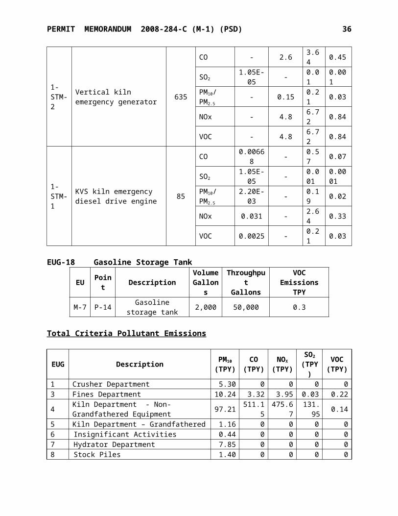
PERMIT MEMORANDUM 2008-284-C (M-1) (PSD) 36
Efficiency(%)
CO Catalytic Incineration 90-95a
Proper Kiln Design and Operation Base Case
SO2
Wet Scrubbing ≤95Dust Collector (Dry Scrubbing)a >95Proper Kiln Design and Operation Base Case
4. Top-Down Evaluation of Control Options and BACT Selection
The highest ranked control option is evaluated first. If this option is technically and economically feasible, and the option has acceptable energy and adverse environmental impacts, the option is deemed BACT. Otherwise, the next ranked control option is evaluated. The evaluation process continues until a control option is found that meets all of the BACT requirements. Once BACT is determined, it is unnecessary to evaluate any remaining options that are ranked below the selected BACT.
The following table shows the results of the RBLC search for lime kilns. SUMMARY OF RBLC SEARCH RESULTS
Company Location Permit Date
COlb/ton-lime
COTechnology
SO2
lb/ton-lime
SO2
Technology
MARTIN MARIETTA
MATERIALSOH 11/13/08 8.33 N/I* 7.08 N/I
CLM - SUPERIOR WI 8/16/06 3.11
GOOD COMBUSTION
PRACTICES1.24
BAGHOUSE, 2% FUEL SULFUR
LIMIT
GRAYMONT (WI) LLC WI 2/6/09 1.56
GOOD COMBUSTION
CONTROL 1.11
2% FUEL SULFUR LIMIT,
INHERENT PROCESS
COLLECTION OF SOX
CHEMICAL LIME
COMPANY - O''NEAL
AL 3/23/05 2.50 N/I 2.05 N/I
ARKANSAS LIME
COMPANYAR 8/30/05 3.00
PROPER KILN DESIGN AND OPERATIONS
1.57**
DRY SCRUBBING BY
LIME PRODUCTION, FUEL SULFUR
LIMITSGRAYMONT
BELLEFONTE PA 7/9/04 28.62 N/I 6.1 LOW SULFUR FUEL
GRAYMONT BELLEFONTE PA 7/9/04 6.00 N/I 2.12
LOW SULFUR FUEL AND WET
SCRUBBER
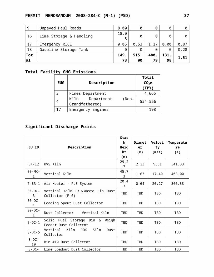
PERMIT MEMORANDUM 2008-284-C (M-1) (PSD) 37
Company Location Permit Date
COlb/ton-lime
COTechnology
SO2
lb/ton-lime
SO2
Technology
GRAYMONT BELLEFONTE PA 7/9/04 2.5 N/I 2.93 N/I
WESTERN LIME CORP. MI 1/30/04 N/I
EFFICIENT FUEL
COMBUSTIONN/I
PREHEATER AND
BAGHOUSECARMEUSE
LIME - MAPLE GROVE
OH 10/14/03 10.00 N/I 40.69 N/I
AUSTIN WHITE LIME COMPANY -
MCNEIL
TX 11/19/03 N/I
CYCLONE/ WET SCRUBBER,
CYCLONE/BAGHOUSE
N/I
CYCLONE/ WET SCRUBBER,
CYCLONE/BAGHOUSE
VULCAN MATERIALS IL 10/28/02 3.12 N/I 2.07
SULFUR CONTENT OF FUEL; DUST COLLECTOR.
VULCAN MATERIALS IL 10/28/02 43.2
BEST COMBUSTION
PRACTICE4.94 BAGHOUSE
AND SCRUBBER
*N/I = None Indicated** The BACT limit was expressed in terms of fuel sulfur content. The corresponding lb/ton limit is back calculated as follows: (44.8 lb SO2/hr) /(687 ton lime/day) / (24 hr/day) = 1.57 lb SO2/ton limeCarbon Monoxide
Catalytic Incineration
A catalytic incineration (CI) system is designed so that combustion gases pass over a catalyst where the CO is converted into CO2. The CI process can achieve 90 to 95 percent conversion of CO. However, the catalyst would be poisoned by the lime dust and the SO2 generated from coal combustion. If the CI system is placed downstream of the baghouse, the problem of catalyst poisoning from the dust can be overcome to a certain degree. Although such a CI system is technically feasible, it is economically infeasible due to the high capital and operating expenses. Based on an analysis for a kiln at another U.S. Lime plant, the cost of CI for a lime kiln was over $9,000 per ton of CO removed. CI is not a demonstrated control technology for lime kilns. Therefore, CI is not considered to be BACT for CO.
Proper Kiln Design and Operation
A properly designed and operated kiln effectively functions as a thermal oxidizer. Carbon monoxide formation is minimized when the kiln temperature and excess oxygen availability is adequate for complete combustion. There are no incremental costs associated with optimal operation of the kiln. Hence, proper kiln design and operation is the most effective control option for CO. Proper kiln design and operation is supported by recent entries in the RBLC.
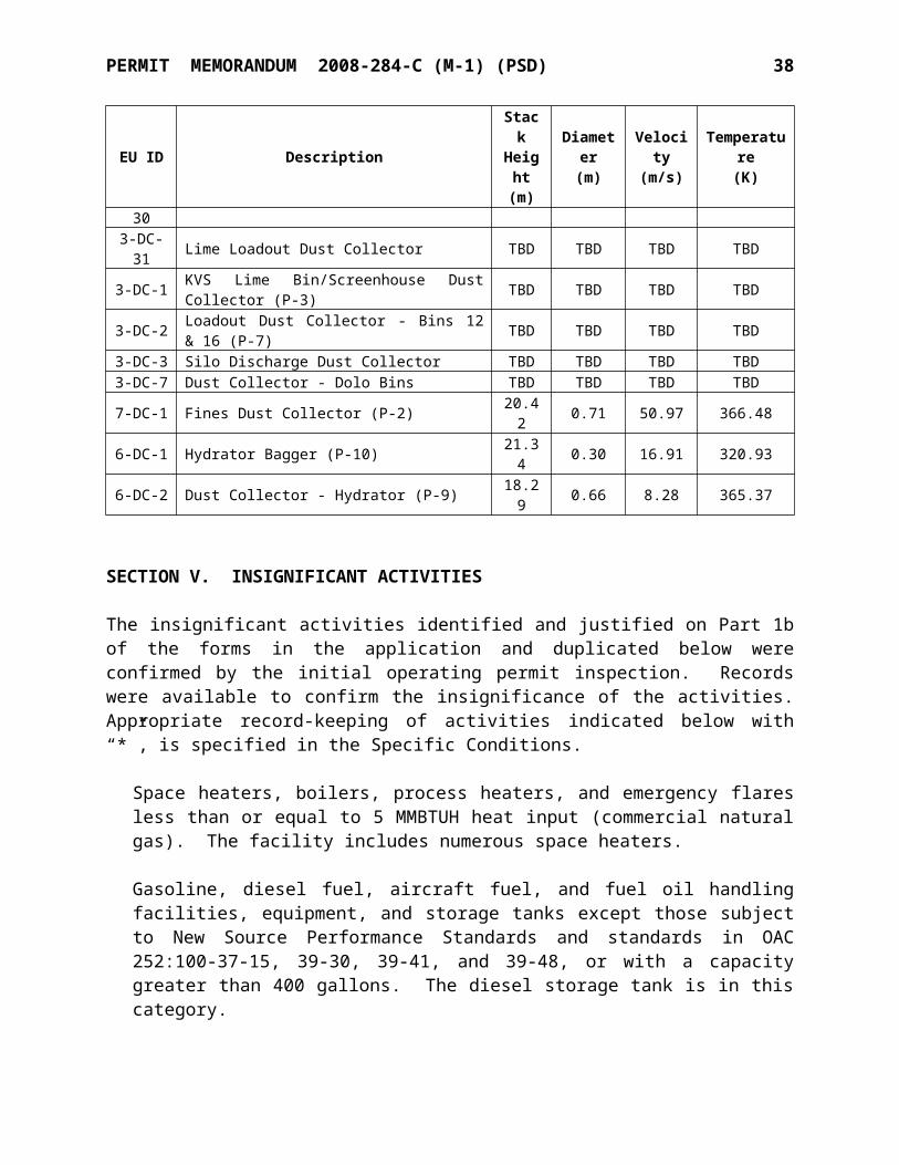
PERMIT MEMORANDUM 2008-284-C (M-1) (PSD) 38
Sulfur Dioxide
Wet Scrubbing
Wet scrubbing in the electric power industry using an agent such as pulverized limestone or lime achieves effective SO2 removal (≤95%). The lime kiln system, however, acts as a large dry scrubber with an inherent SO2 control efficiency of 90 to 95%. Due to this effective SO2 control, wet scrubbing is unnecessary and due to the environmental impact of excessive water usage and water treatment requirements is not used in the modern lime industry for SO2 control. The use of a baghouse for particulate control provides SO2 control by means of contact of the exhaust gas and lime dust filter cake forming in the dust collector. The new vertical kiln with dry baghouse is expected to have a SO2 removal efficiency greater than 95%. Due to the SO2 control inherent to dry lime kiln dust collection systems and the adverse environmental impact of wet scrubbing, wet scrubbing is eliminated from consideration as BACT.
Dry Scrubbing with a Dust Collector
As mentioned above, rotary lime kiln systems act as a large dry scrubber. This inherent SO 2
control represents BACT in recent permits. For control of particulate emissions, dust collectors are the most efficient and effective proven technology. The contact of the exhaust gas and lime dust filter cake formed in the dust collector also provides SO2 removal. Given the inherent SO2
control in lime kilns and use of a baghouse, it is expected that SO2 removal efficiency at the new vertical kiln to be above 95%. Thus, the inherent dry scrubbing with a dust collector is BACT for SO2 control.
The following table summarizes the results of the BACT analysis for the Vertical Kiln. These BACT limits are inclusive of periods of normal operation as well as periods of routine maintenance, startup, and shutdown (MSS).
BACT SUMMARY FOR THE VERTICAL KILNPollutant Emission Limit Control Technology
CO 4.22 lb/ton of lime produced Good combustion practicesSO2 0.868 lb/ton of lime produced Regenerative vertical kiln design, and dust collector (dry scrubbing)
BACT Determination for Natural Gas-Fired Sources
The 5 MMBtu/hr air heater used in the new vertical kiln Bowl Mill, and the 3.5 MMBtu/hr baghouse startup heater will have CO emissions (and negligible SO2 emissions). Therefore, these emission units are subject to a BACT analysis. For SO2 emissions, BACT is the use of only natural gas as a fuel for these heaters. For CO emissions, the use of natural gas and good combustion practices is considered as BACT. Add-on control devices for small gas-fired sources are not technically or economically feasible.
B. AIR QUALITY IMPACTS
PERMIT MEMORANDUM 2008-284-C (M-1) (PSD) 39
Prevention of Significant Deterioration (PSD) is a construction permitting program designed to ensure air quality does not degrade beyond the National Ambient Air Quality Standards (NAAQS) or beyond specified incremental amounts above a prescribed baseline level. The PSD rules set forth a review procedure to determine whether a source will cause or contribute to a violation of the NAAQS or maximum increment consumption levels. If a source has the potential to emit a pollutant above the PSD significance levels, then it triggers this review process.
EPA has provided significance impact levels (SIL) for the PSD review process to determine whether a source will cause or contribute to a violation of the NAAQS or consume increment. Air quality impact analyses were conducted for CO and SO2 to determine if ambient impacts would be above the SIL and monitoring significance levels (MSL). If impacts are above the SIL, a radius of impact (ROI) is defined for the facility for each pollutant out to the farthest receptor at or above the SIL.
The ROI is used to determine the distance out to which nearby sources need to be reviewed for inclusion in the NAAQS and increment modeling. The nearby source inventories for each pollutant that exceeded the SIL were obtained from the AQD using the determined ROI. Inventory sources within the facility’s ROI plus 50 km are included in the full impact analysis. If the facility is within 50 km of another state, a list of sources must be obtained for that state. Since the U.S. Lime facility is within 50 km of Arkansas, inventory sources within the ROI plus 50 km extending into that state were evaluated as well. The Arkansas inventory sources were not included in the NAAQS modeling analysis for either 1-hour or 3-hour SO2 modeling as they did not have a significant concentration gradient in the modeling domain.
AERMOD (versions 09292 and 11103) was used for the modeling analyses. AERMOD is a refined, steady-state, multiple source, Gaussian dispersion model and is the preferred model for these analyses. The modeling analysis was performed using the regulatory default models settings, which include stack heights adjusted for stack-tip downwash and missing data processing. Source, building, and receptor terrain elevations were obtained from processing USGS 7.5 minute digital elevation model (DEM) files with AERMAP (version 09040).
In order to account for building wake effects, direction-specific building dimensions used as input to the model were calculated using the algorithms of the Building Profile Input Program (BPIP). BPIP is designed to incorporate the concepts and procedures expressed in the GEP Technical Support document, and the Building Downwash Guidance document while incorporating the enhancements to improve prediction of ambient impacts in building cavities and wake regions.
As described in the Air Dispersion Modeling Guidelines for Oklahoma Air Quality Permits, meteorological data was derived from Oklahoma Mesonet surface data, National Climatic Data Center (NCDC) Integrated Surface Hourly (ISH) data, and FSL/NCDC Radiosonde upper air data. Oklahoma Mesonet data was provided to the AQD courtesy of the Oklahoma Mesonet, a cooperative venture between Oklahoma State University and The University of Oklahoma and supported by the taxpayers of Oklahoma. The model runs were performed using 2001-2005 meteorological data using NWS surface observations from Cookson mesonet site and IHS data
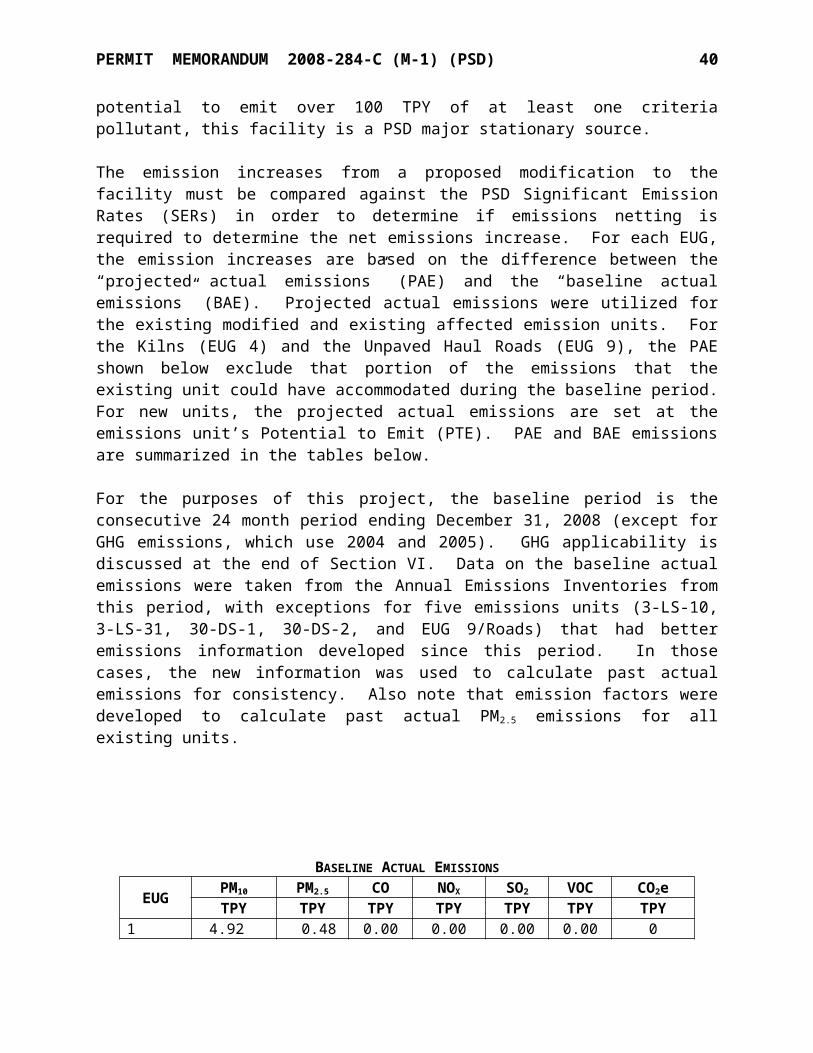
PERMIT MEMORANDUM 2008-284-C (M-1) (PSD) 40
from Muskogee, OK (NWS number 723556). Upper air meteorological data were from Springfield, Missouri. The 2001-2005 data set used in this analysis was provided by the AQD.
Receptor Grids
The initial air quality analysis was conducted using three Cartesian grids, and was defined as follows:
1. A fence line grid containing 25-meter spaced receptors located along the facility property line.
2. A fine grid containing 100-meter spaced receptors, extending approximately 1 km from the fence line.
3. A medium grid containing 500-meter spaced receptors, extending approximately 5 km from the fence line.
4. A coarse grid containing 1000-meter spaced receptors, extending approximately 15 km from the fence line.
The receptor grids above were utilized in the analyses for the pollutants in the following table.
AIR QUALITY ANALYSES USING 15 KM RECEPTOR GRIDAnalysis Type Pollutant Averaging Period
NAAQS SO2 3-hr
PSD Increment SO2
3-hr24-hr
Annual
Due to the extent of impacts on the SO2 1-hour averaging period, a second round of modeling was conducted using Cartesian grids extending out to 50 km, and was defined as follows:
1. A fence line grid containing 25-meter spaced receptors located along the facility property line.
2. A fine grid containing 100-meter spaced receptors, extending approximately 1 km from the fence line.
3. A medium grid containing 500-meter spaced receptors, extending from approximately 1 km to 5 km from the fence line.
4. A coarse grid containing 1000-meter spaced receptors, extending from approximately 5 km to 25 km from the fence line.
5. A coarse grid containing 2000-meter spaced receptors, extending from approximately 25 km to 50 km from the fence line.
The receptor grids above were utilized in the analyses for the pollutants in the following table.
AIR QUALITY ANALYSES USING 50 KM RECEPTOR GRID
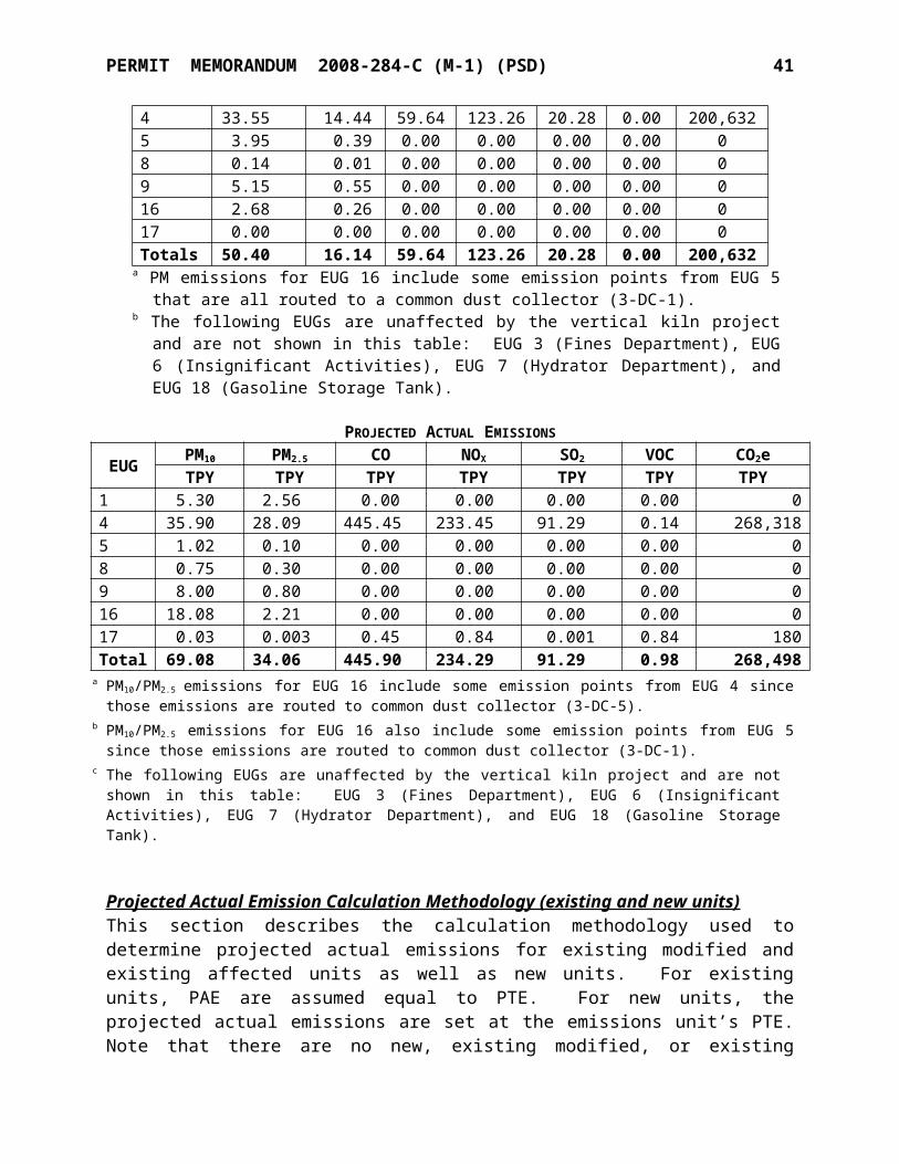
PERMIT MEMORANDUM 2008-284-C (M-1) (PSD) 41
Analysis Type Pollutant Averaging Period
NAAQSSO2 1-hr
CO 1-hr8-hr
Significance Analysis
A significance analysis was conducted to determine if CO and SO2 exceeded their respective SIL, and if so, to establish a radius of impact (ROI) for them. EPA requires that a full impact analysis be conducted if the project emissions result in maximum predicted concentrations exceeding the SIL. U.S. Lime modeled the potential emissions from the project in this analysis. The following tables list the model parameters and the results from the significance analyses. Note that a 10 MMBtu/hr natural gas burner (7-BR-20) was originally part of the project scope and was included in the modeling analyses. Prior to issuance of this permit, U.S. Lime removed this burner from the project scope. The modeling was not revised since removal of this burner would only serve to reduce the modeled concentrations.
Modeled Source Parameters
EU # DescriptionUTM
EUTM
NStackHeight
StackTemp
ExitVelocity
StackDiameter
(m) (m) (m) (K) (m/s) (m)30-MK-1 Vertical Kiln 334097 3940641 45.73 403.00 17.40 1.63P-8 (shutdown) Fuller Kiln 333939 3940553 30.48 341.48 14.36 2.135-BR-1 Air Heater - Vertical Kiln Bowl Mill 334074 3940552 15.24 349.67 23.39 0.5441-STM-2 Emergency Generator - Vertical Kiln 334107 3940633 4.88 824.67 52.04 0.20
Modeled Source Emissions
EU # Description CO SO2
(lb/hr) (lb/hr)30-MK-1 Vertical Kiln 105.5 21.7P-8 (shutdown) Fuller Kiln -22.75 -7.745-BR-1 Air Heater - Vertical Kiln Bowl Mill 0.42 0.011-STM-2 Emergency Generator - Vertical Kiln 3.64 0.007
Class II Significance Analyses SummaryCO CO SO2 SO2
8-Hour 1-Hour 3-Hour 1-Hourµg/m3 µg/m3 µg/m3 µg/m3
Maximum Modeled Concentration 214 590 89 111Class II SIL 500 2,000 25 7.9Monitoring De Minimis 575 - - -Full Impact Analysis Required? No No Yes Yes
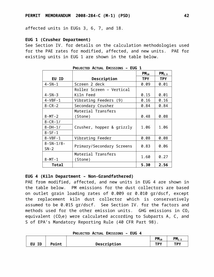
PERMIT MEMORANDUM 2008-284-C (M-1) (PSD) 42
As seen above, SO2 1-hr and 3-hr averaging periods exceeded their respective Class II SIL. Therefore, a full impact analysis consisting of both a Class II NAAQS analysis and a Class II PSD increment analysis was performed. Note that SO2 NAAQS standards for the 24-hr and annual averaging periods were revoked in Primary National Ambient Air Quality Standard for Sulfur Dioxide (Final Rule), published in the Federal Register on June 22, 2010. Therefore, a NAAQS analysis is not required for those averaging periods.
Full Impact Analysis
NAAQS Analysis
To complete the NAAQS Analysis, the proposed emissions from the facility were modeled simultaneously with the emissions from the NAAQS sources identified in the nearby source inventory provided by the AQD. The inventory sources included in the modeling were the AES Cogeneration Plant in LeFlore County, the OG+E Muskogee Generating Station, and the Georgia-Pacific Muskogee Mill. Potential emission rates were modeled. The background concentration was added to the modeled concentration for comparison with the NAAQS for the SO2 3-hr averaging period. Monitoring data from U.S. EPA’s AirData system for the most recent year (2008) was utilized to develop background concentrations for use in the SO2 3-hr NAAQS analysis. The Park Hill monitor was used as the most representative monitoring data.
NAAQS Background Concentration
Pollutant Averaging Period Monitored Concentration(μg/m3)
Monitor SiteAddress
SO2 3-Hour 26.65 35.854° N, 94.985° WNotes:1 The highest second highest (H2H) monitored concentration for CY 2008.
U.S. EPA’s 1-hour NO2 Guidance Memo (p. 18) states the following regarding background concentrations:
If the background source inventory included in the modeling is complete enough and background levels due to mobile sources and/or minor sources that are not explicitly modeled is expected to be small, an analysis based solely on modeled emissions and no monitored background might be considered adequate for purposes of the cumulative impact assessment.
Based on the 1-hour NO2 Guidance Memo and verbal approval from the AQD, a background concentration was not added to the modeled SO2 1-hr concentration for comparison to the NAAQS.
The proposed SO2 emissions from the facility were modeled simultaneously with the SO2
emissions from the NAAQS inventory sources. The five-year average 4 th high daily maximum 1-hour SO2 concentration and the second highest high 3-hr SO2 concentration are compared against NAAQS. The results are listed in the following table.
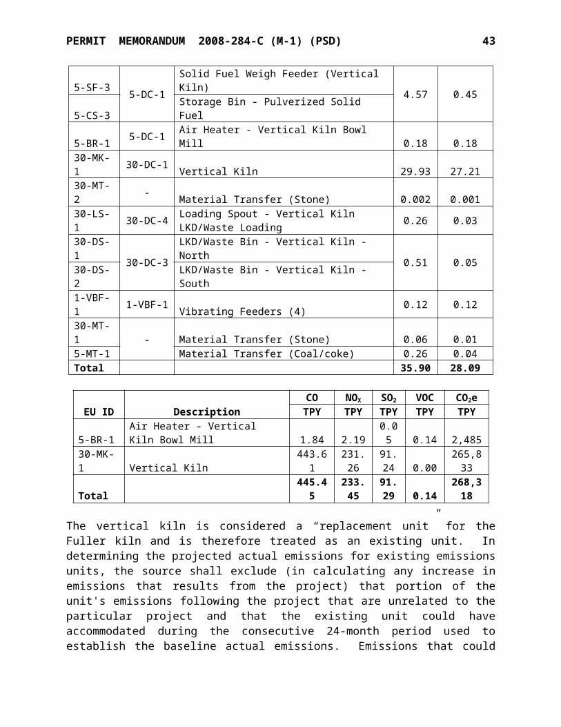
PERMIT MEMORANDUM 2008-284-C (M-1) (PSD) 43
NAAQS Analyses Results
SO2 SO2
3-Hour 1-Hourµg/m3 µg/m3
Maximum Modeled Results 707.5 416Background Concentration 26.6 -Total Concentration 734 416NAAQS 1,300 196Violation? No Yes
This analysis shows that the proposed project SO2 emissions will not cause or contribute to a violation of the SO2 3-hr NAAQS. Since this analysis showed a NAAQS exceedance for the 1-hr SO2 standard, U.S. Lime conducted a cause and contribute analysis to determine if the project caused or contributed to any 1-hr SO2 NAAQS violations.
The model input for the 1-hr SO2 NAAQS analyses are listed below:
1. Only the significant receptors5 were modeled (1,758 receptors as determined from the significance analysis).
2. MXDYBYYR output option was selected in AERMOD (11103).
From this model run, U.S. Lime deduced that NAAQS exceedances occurred at 618 unique receptor locations and from the 4th through the 18th highs. To determine if the project caused or contributed to any 1-hour SO2 NAAQS exceedance, a second SO2 NAAQS modeling analysis was performed utilizing the following:
1. 618 receptors at which NAAQS exceedances occurred 2. MAXDCONT keyword for the “NAAQS” source group6
3. 4th through 18th highs
The MAXDCONT output was then analyzed in Microsoft Excel. The results of the MAXDCONT “cause or contribute” analysis are summarized in the following table.
Cause or Contribute AnalysisProject Contributions > SIL
MaximumImpact4
Project > 7.9And
NAAQS > 196?
U.S. Lime CauseOr
Contribute to Violation?
Numberof
Receptors
NumberOf
ReceptorEvents
Ranks(Nth Highs)
36 74
5th
6th
11th
14th
15th
195.7 No No
5 Receptor locations at which the first highest high concentration exceeded the 1-hr SO2 SIL, 7.9 µg/m3.6 The “NAAQS” source group contains the U.S. Lime post-project emission rates and the regional inventory source emission rates.
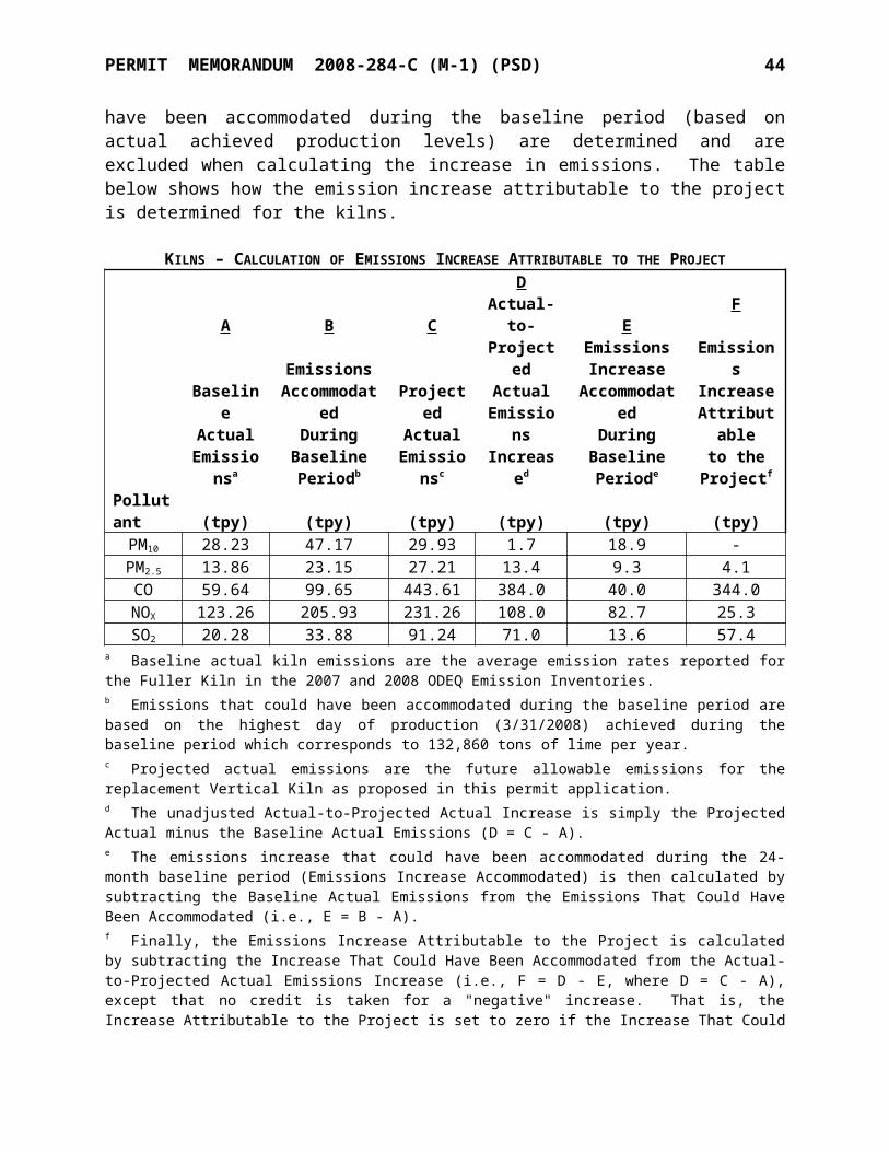
PERMIT MEMORANDUM 2008-284-C (M-1) (PSD) 44
16th
17th
18thNotes:1 Results were obtained from the MAXDCONT post-processing routine of EPA's AERMOD v. 11103.2 Receptor-event is a term used to describe an event paired in time and space (i.e., for a particular receptor and Nth High.3 U.S. Lime Project contributions exceeded the 1-hour SO2 SIL (7.86) at 36 unique receptors that spanned the nth highs listed in this table, for a total of 74 receptor-events.4 The highest daily maximum 1-hour concentration (resulting from post-project and regional source emissions) among the 74 receptor-events that exceeded the SIL.5 At each of the 74 receptor-events where the Project concentrations exceeded the SIL, theNAAQS concentration was below the 1-hr SO2 NAAQS (196). Therefore, the Project doesnot cause or contribute to any of the 1-hr SO2 violations.
As seen in the table above, project concentrations exceeded the SIL (7.9 µg/m3) at 36 unique receptors for various Nth highs (among those listed in the table) for a total of 74 receptor-events7
that exceeded the SIL. Among the 74 receptor-events where project concentrations were significant, there were no “NAAQS” source group (post-project and inventory source emissions) concentrations that exceeded the 1-hour SO2 NAAQS (196 µg/m3). When evaluating all receptor-events where the project concentrations were significant, the highest 5-year average daily maximum 1-hour concentration for the “NAAQS” source group was 195.7 µg/m3 which occurred at the fifth high daily maximum. Therefore, the Project does not cause or contribute to any 1-hour SO2 NAAQS violation.
Class II PSD Increment Analysis
The PSD increment is the maximum allowable increase in concentration that is allowed to occur above a baseline concentration for a pollutant. The major source baseline date depends upon the county in which the facility is located and on the pollutant in question. Sources that contribute to emissions increases after the baseline date are obtained from the AQD, and total facility-wide potential emissions are modeled simultaneously with the PSD Increment inventory sources provided by the AQD.
The 3-hour, 24-hour, and annual averaging periods were modeled for the PSD increment. No increment analysis was performed for the SO2 1-hour standard, because currently, there is not a SO2 1-hour increment. The second highest high short-term (24-hour and 3-hour averaging periods) impacts among all five years of meteorological data are compared to the 3-hour and 24-hour SO2 PSD increments. The maximum annual impact among all five years of meteorological data is also compared to the annual SO2 PSD increment. The following table lists the PSD increment analysis results.
Class II PSD Increment AnalysisSO2 SO2 SO2
3-Hour 24-Hour Annual
7 Receptor-event is a term used to describe an event paired in space and time (i.e., an event at a receptor for a certain rank, or nth High).
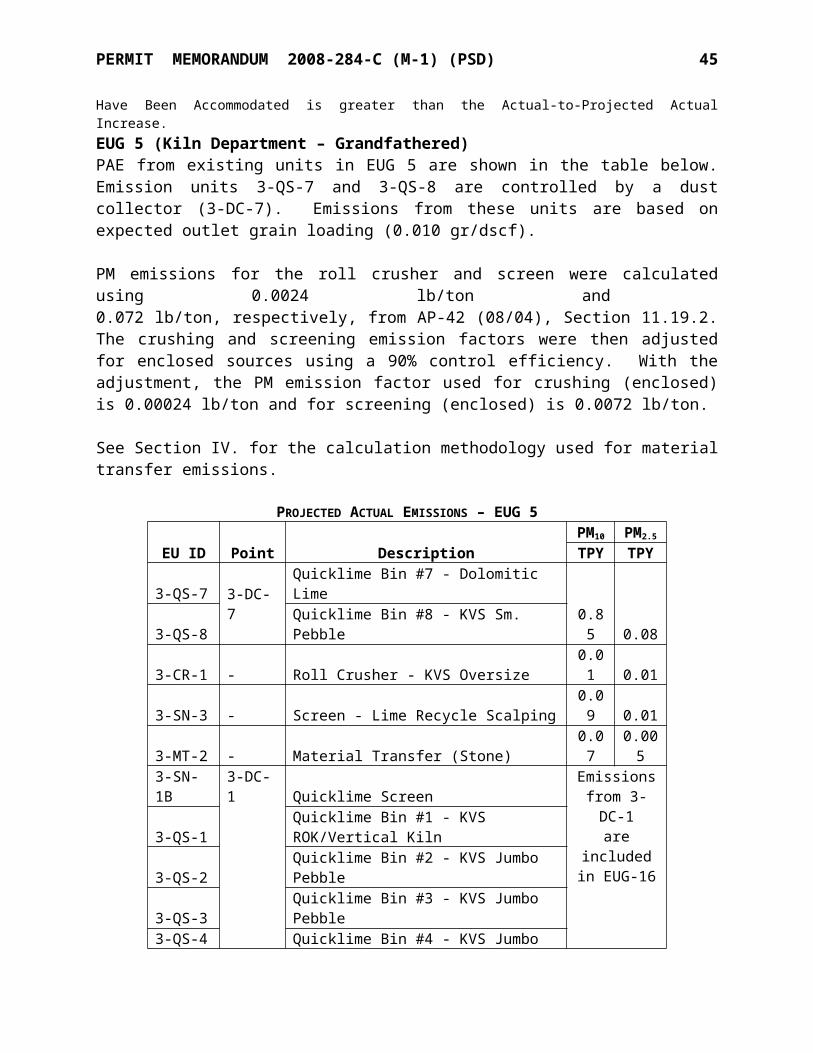
PERMIT MEMORANDUM 2008-284-C (M-1) (PSD) 45
µg/m3 µg/m3 µg/m3
Maximum Modeled Results 120 24 4Class II PSD Increment 512 91 20Exceed Increment? No No No
Class I Area Analysis
PSD regulations require a Class I area analysis be conducted for all proposed sources with potential for air quality impacts on a Class I area. Class I areas are federally protected areas for which more stringent air quality standards apply to protect unique natural, cultural, recreational, and/or historic values.
The four Class I areas nearest to the Marble City facility are:
1. Upper Buffalo Wilderness Area in north-central Arkansas, located approximately 130 kilometers northeast of the facility.
2. Caney Creek Wilderness in Western-central Arkansas, located approximately 149 km southeast of the facility.
3. Hercules-Glades Wilderness in southwestern Missouri, located approximately 209 km northeast of the facility,
4. Wichita Mountains National Wildlife Refuge in southwestern Oklahoma, located approximately 366 km southwest of the facility.
Two principal air quality impact evaluations are typically considered for Class I areas: PSD Increments and Air Quality Related Values (AQRV). A PSD Class I Increment significance analysis was performed for the project emission increases of SO2. A visibility screening analysis was conducted for AQRV using VISCREEN and the Q/D method.
PSD Class I Increment Significance Analysis
The Class I increment significance analysis was performed for the two Class I areas nearest to the Marble City Facility: Upper Buffalo Wilderness Area and Caney Creek Wilderness Area. To evaluate potential impacts at the distant Class I areas, an arc containing three receptors was placed 50 km (the maximum distance AERMOD can accurately model) from the center of the U.S. Lime facility in the directions of both the Upper Buffalo and Caney Creek areas. The same meteorological data set as mentioned previously in this permit was used in this analysis. As noted in the following table, the maximum SO2 impacts for the 3-hr, 24-hr, and annual averaging periods fall below the Class I significant impact levels (SILs). Since the resulting concentrations show insignificant results at 50 km, it is reasonable to conclude that concentrations would also be below the Class I SILs at 130 km and 149 km (the distances of the two Class I areas). Therefore, a full impact Class I analysis is not required.
Class I Significance Analysis Results
Pollutant AveragingPeriod
SIL(µg/m3)
Maximum Modeled
Concentration(µg/m3)
Full ImpactAnalysis
Required?
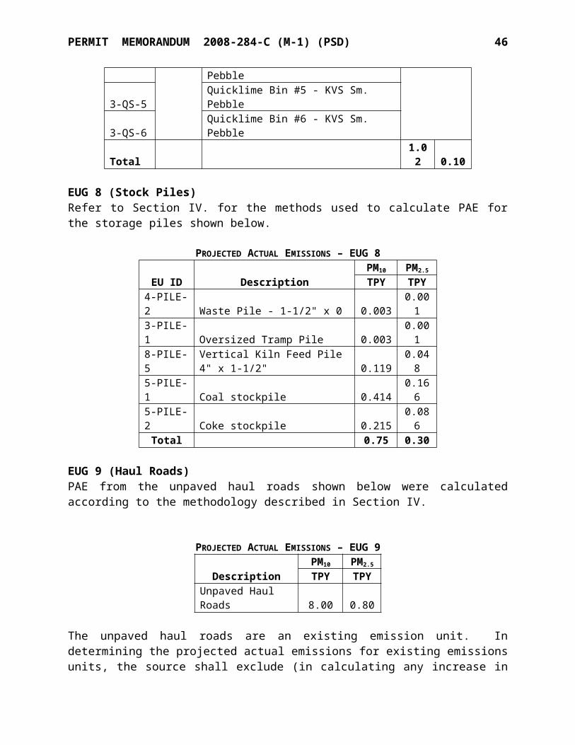
PERMIT MEMORANDUM 2008-284-C (M-1) (PSD) 46
SO2 3-hr 1 0.96 No24-hr 0.2 0.16 NoAnnual 0.1 0.01 No
Class I Visibility Impairment Analysis (AQRV)
To conduct a visibility impairment analysis for Class I areas, U.S. EPA prescribes the use of its Workbook for Plume Visual Impact Screening and Analysis. Three levels of screening procedures are outlined by U.S. EPA. If the criteria for the first, most conservative, screening level are met, no further analysis is required. The VISCREEN model is recommended for the first level (Level 1) screen. As detailed in the permit application, the results of the Level 1 visibility analysis for this permit application were below the standardized screening criteria. Therefore, no visibility impairment will result from the project and no additional analysis is required.
In addition to the VISCREEN analysis, U.S. Lime utilized a method recommended by the Federal Land Managers (FLMs) for Class I Area impact analyses. As an alternative to the standard Class I analysis, the FLMs consider a source located greater than 50 km from a Class I area to have negligible impacts with respect to Class I air quality related values (AQRV) if its total SO2, NOX, PM10, and H2SO4 annual emissions (in tpy, based on 24-hour maximum allowable emissions), divided by the distance (in km) from the Class I area (Q/D) is 10 or less. The FLMs would not request any further Class I AQRV impact analyses from such sources. Asummary of Q/D screening results is given in the table below.
10D Rule Screening Analysis
Class I Area Quantity(Q tpy)
Minimum Distance(D km) Q/D Q/D<10?
Caney Creek 915.6 148.8 6.2 YesHercules Glade 915.6 209.4 4.4 YesUpper Buffalo 915.6 129.9 7.1 YesWichita Mountains 915.6 366.2 2.5 Yes
Based on the results above, a Class I AQRV analysis is not required. In addition, U.S. Lime’s distance from the Class I areas and calculated Q/D ratios indicate that U.S. Lime would not have a measurable impact on the PSD increments in these areas.
C. ADDITIONAL IMPACTS ANALYSIS
Growth Impact
The elements of the growth analysis include a projection of the associated industrial, commercial, and residential growth that will occur in the area of impact attributable to the source, including the potential impact on ambient air resulting from this growth. The Marble City facility is an existing facility, and this project will not cause a significant shift of population or an appreciable increase in industrial, commercial, and residential growth in the area. Since no significant associated commercial, industrial, or residential growth is expected as a result of the project, negligible growth-related ambient air impacts are expected.
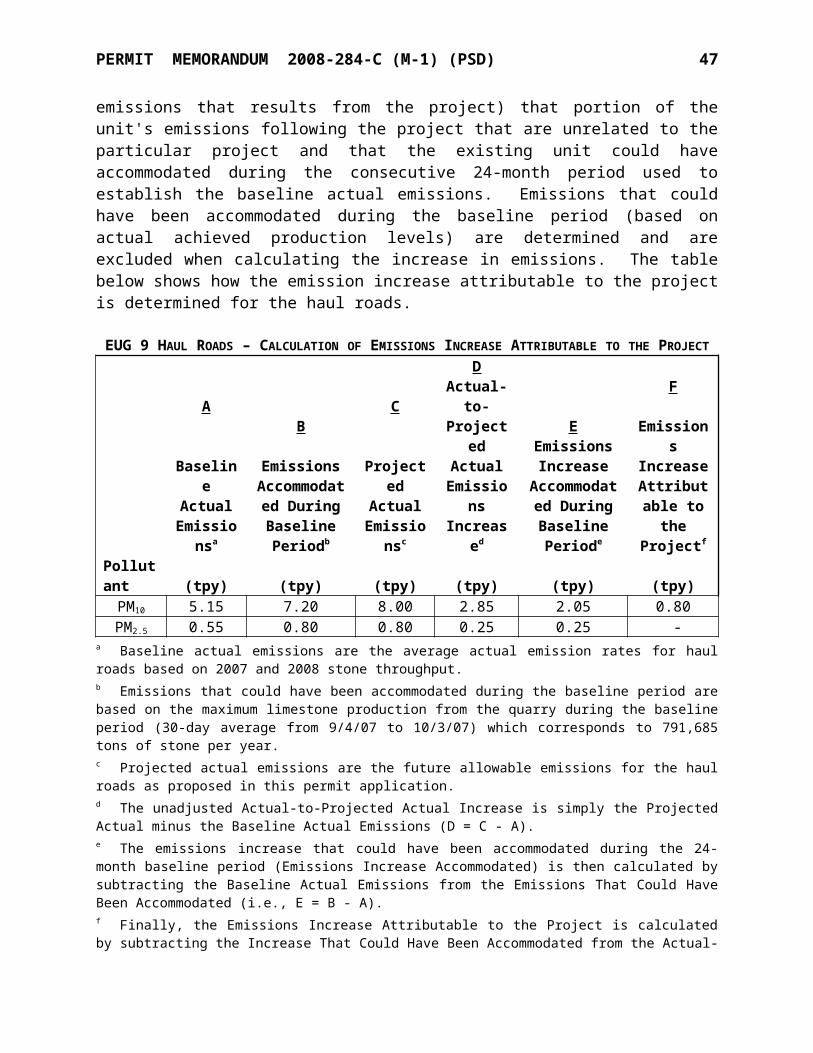
PERMIT MEMORANDUM 2008-284-C (M-1) (PSD) 47
Soil and Vegetation Impact
The effects of gaseous air pollutants on vegetation may be classified into three rather broad categories: acute, chronic, and long-term. Acute effects are those that result from relatively short (less than 1 month) exposures to high concentrations of pollutants. Chronic effects occur when organisms are exposed for months or even years to certain threshold levels of pollutants. Long-term effects include abnormal changes in ecosystems and subtle physiological alterations in organisms. Acute and chronic effects are caused by the gaseous pollutant acting directly on the organism, whereas long-term effects may be indirectly caused by secondary agents such as changes in soil pH.
The EPA developed the secondary NAAQS in order to protect certain air quality-related values (e.g., soils and vegetation) that were not sufficiently protected by the primary NAAQS. The secondary NAAQS represent levels below which most types of soil and vegetation are unaffected by criteria pollutants. Since the predicted ambient impacts are well below the secondary SO2 NAAQS, this project will not result in harmful effects to either soil or vegetation.
Visibility Impairment
Class II Visibility
A screening analysis was conducted in order to evaluate the U.S. Lime modification’s impact on Class II visibility. VISCREEN, the screening tool recommended for Class I visibility screening analyses, was used per guidance provided by the Oklahoma DEQ.
The default meteorological conditions of F-stability and 1 m/s wind speed were used. For emission rates, only annual emissions of NOX and PM from the total facility emissions were input into the model. The default values were chosen for primary NO2, soot, and primary sulfate emissions. A background visual range of 40 km was used.
Based upon a geographic analysis of the local area, the Marble City facility is not located within 40 km of any of the sensitive areas, and therefore, distances to sensitive areas are not required to be utilized in the analysis. This distance (40 km) was used for source-observer input distance. In addition, since this Class II analysis does not involve a formal Class I area boundary, a Class II boundary was selected (per DEQ guidance) extending from 40 km to 50 km from the source.
VISCREEN analyzes a matrix of conditions for regions within and outside the Class I area boundaries (in this case, the “Class II” boundaries). This matrix includes forward scattering and backward scattering impacts viewed against the sky and the surrounding terrain (e.g., mountains, hills, etc.). The forward scattering case assumes that the sun is in front of the observer at an angle of 10° above the horizon. The backward scatter case assumes that the sun is at the observer’s back at an angle of 140° above the horizon.
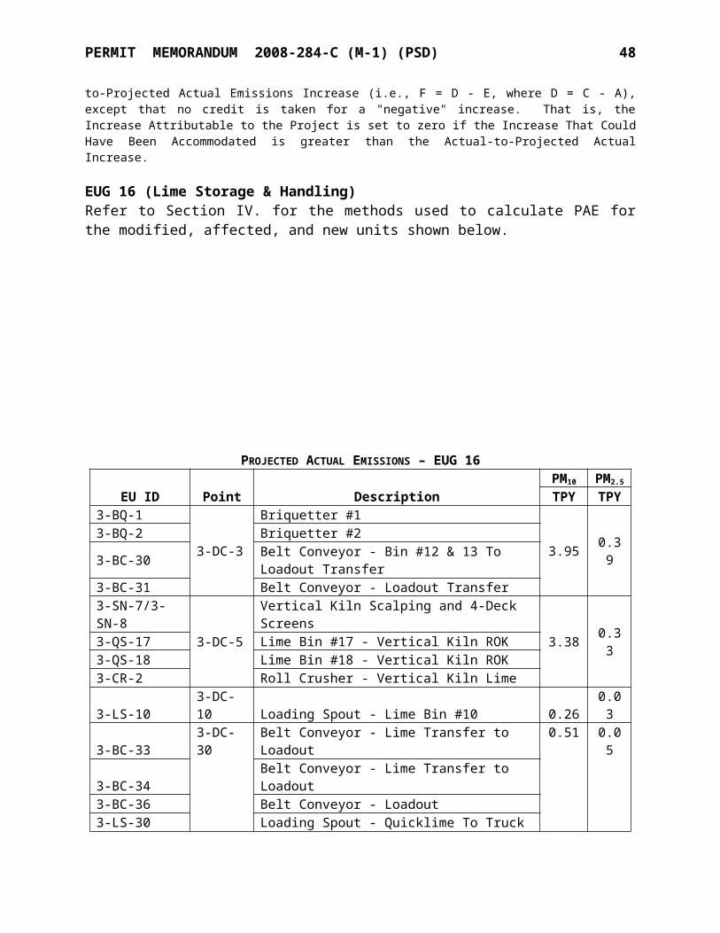
PERMIT MEMORANDUM 2008-284-C (M-1) (PSD) 48
Results from the VISCREEN model are expressed in terms of perceptibility (∆E) and contrast. The EPA default Class I screening criteria for perceptibility and contrast are 2.0 and 0.05, respectively. For a Class II analysis, the AQD guidance suggests that 3 × the screening criteria be used, resulting in perceptibility and contrast thresholds of 6.0 and 0.15.
VISCREEN Results – Class II Visibility
Background Theta Azimuth Dist. Alpha ∆E Contrast(degrees) (degrees) (km) (degrees) Critical Plume Critical Plume
SKY 10 84 40 84 6 1.716 0.15 0.014SKY 140 84 40 84 6 0.543 0.15 -0.014TERRAIN 10 84 40 84 6 1.18 0.15 0.014TERRAIN 140 84 40 84 6 0.21 0.15 0.009
As seen from these results, the results for perceptibility and contrast criteria are well below the respective thresholds when viewed against a sky background and against terrain. Therefore, the predicted impact will not result in visibility impairment.
D. GREENHOUSE GAS (GHG) APPLICABILITY
On May 13, 2010, EPA issued the final GHG Tailoring Rule. This rule effectively raised the thresholds for GHG emissions that define when permits under the PSD and Title V OperatingPermit programs are required for new and existing industrial facilities. Without the GHG Tailoring Rule, the thresholds established in the CAA for other pollutants would apply to GHGs. Since this permit was issued after July 1, 2011, the U.S. Lime modification is subject to Phase 2 of the Tailoring Rule. According to Phase 2, an existing facility triggers PSD review for GHG if the following requirements are met:
Modification is subject to PSD for traditional pollutant, and GHG emissions increase and net emissions increase is:o ≥ 75,000 tpy CO2e ANDo ≥ 0 tpy (mass basis)
OR, Both:o Existing facility’s PTE:
> 100,000 tpy CO2e AND > 100/250 tpy (mass basis)
o GHG emissions increase and net emissions increase ≥ 75,000 tpy CO2e AND ≥ 0 tpy (mass basis)
U.S. Lime performed netting calculations to determine the net emissions increase from the proposed project. As seen in the table below, the emissions increase from the proposed modification is below the 75,000 tpy threshold. Therefore, the Marble City facility is not subject to PSD review for GHGs.
GHG Emissions Summary
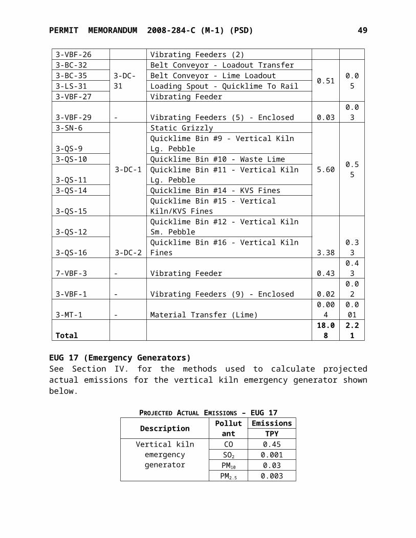
PERMIT MEMORANDUM 2008-284-C (M-1) (PSD) 49
GHG Emissions(CO2e short tons/yr)
Kiln Project Emissions Increase 67,866GHG PSD Threshold 75,000Subject to GHG PSD Review? No
SECTION VII. FEDERAL REGULATIONS
PSD, 40 CFR Part 52 [Applicable]Total facility emissions are greater than the level of significance of 100 TPY of any single regulated pollutant; the facility is one of the 26 specific industries with a threshold of 100 TPY. Any future increases must be evaluated in the context of PSD significance levels: 40 TPY NOx, 100 TPY CO, 40 TPY SO2, 15 TPY PM10, 40 TPY VOC, 10 TPY TRS, or 0.6 TPY lead. The net emission increase for this project exceeds the significance levels for CO and SO2. See PSD review in Section VI.
NSPS, 40 CFR Part 60 [Subpart OOO Applicable]NSPS requires new, modified, or reconstructed sources to control emissions to the level achievable by the best demonstrated technology specified in the applicable provisions. NSPS regulations apply to any “affected” facility, “modification” of an existing affected facility, or “reconstruction” of an existing affected facility for which construction commences after the date of proposal of NSPS. The new Vertical Kiln is a unit associated with the project that may be an “affected” unit pursuant to NSPS.
Subpart Y (Coal Preparation Plants) affects equipment used to crush coal, separate it from refuse, or convey coal which commenced construction, reconstruction, or modification after October 24, 1974. Subpart Y affects the following facilities in coal process plants which process more than 200 TPD: thermal dryers, pneumatic coal cleaning equipment (air tables), coal processing and conveying equipment (including breakers and crushers), coal storage systems, and coal transfer and loading systems. Subpart Y only applies to affected facilities in coal preparation plants that process more than 200 tons of coal per day. The coal requirements for the KVS and Vertical Kilns combined are less than 200 tons per day and Subpart Y is not applicable to the Marble City facility.
Subpart HH (Lime Manufacturing) affects rotary kilns which commenced construction, reconstruction, or modification after May 3, 1977. The KVS kiln was constructed prior to the applicability date, and the modification (conversion to coal fuel) also-predated Subpart HH. The vertical shaft kiln does not meet the definition of “rotary kiln” and is therefore not subject to Subpart HH.
Subpart OOO (Nonmetallic Mineral Processing Plants). The provisions of this subpart are applicable to the following affected facilities in fixed or portable nonmetallic mineral processing plants: each crusher, grinding mill, screening operation, bucket elevator, belt conveyor, bagging operation, storage bin, enclosed truck or rail car loading station. Subpart OOO is applicable to the equipment at the facility which was manufactured after effective date of August 31, 1983.
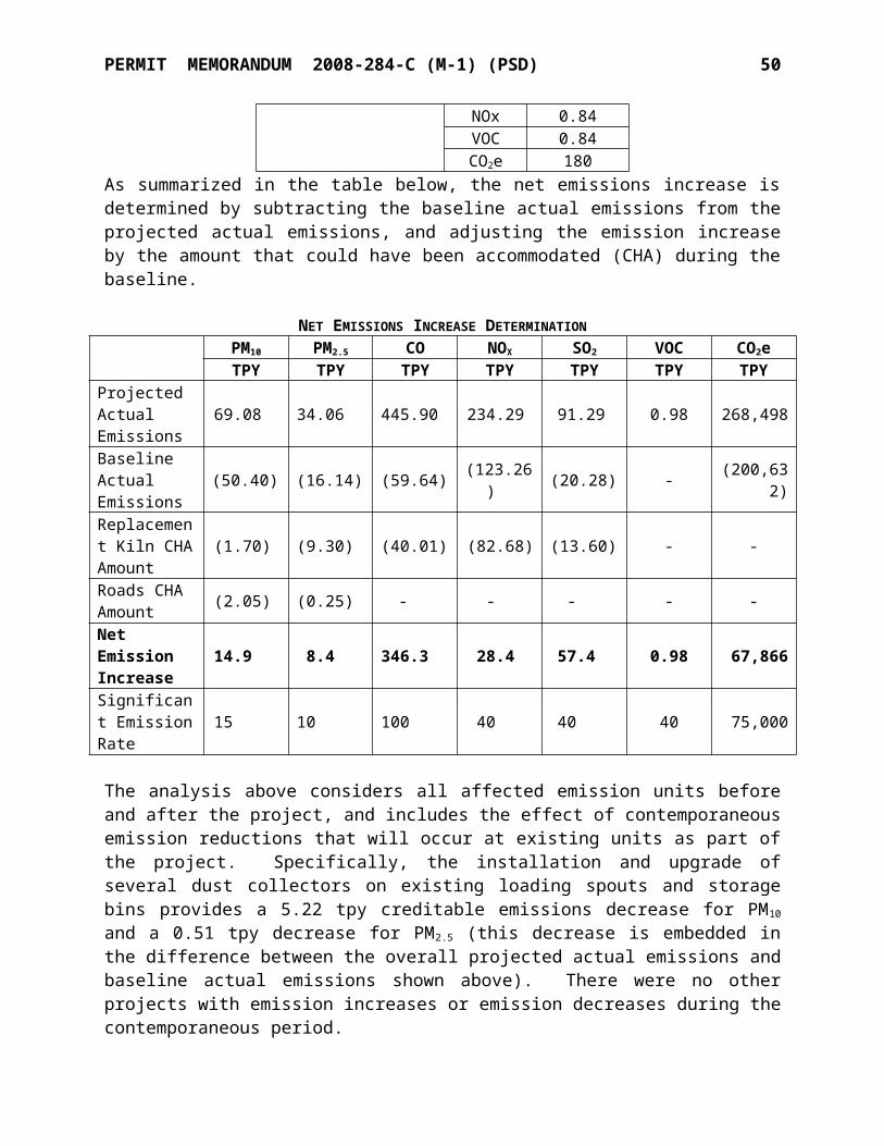
PERMIT MEMORANDUM 2008-284-C (M-1) (PSD) 50
However, new Subpart OOO standards were promulgated on April 28, 2009, and apply to affected facilities that commence construction, modification, or reconstruction on or after April 22, 2008. For this new equipment, Subpart OOO specifies limitations of 0.014 gr/DSCF for stack emissions from affected capture systems and 7% opacity for dry control devices on individual storage bins. However, there are no new affected facilities (individual storage bins) being installed that will be subject to this 7% opacity standard. The opacity from new crushers shall not exceed 12% and the opacity from other new affected facilities (including screens, bucket elevators, conveyor transfer points except transfer to stockpiles, storage bins, and enclosed truck/railcar loading operations) shall not exceed 7% opacity. Table I shows the new or modified affected facilities that will be subject to the post-2008 Subpart OOO limit for fugitive emissions.
Table I. Affected Facilities Subject to Post-2008 Subpart OOO Fugitive Limit
NewEU/Point
Existing EU(Point) Description
Fugitive OpacityLimit
(percent)008-BC-3 EC-7 (F-5)
Crusher Department Belt Conveyors 7
008-BC-3A EC-9 (F-6)008-BC-3B EC-11 (F-8)008-BC-7 EC-17 (F-14)008-BC-8 EC-18 (F-15)008-BC-9 -008-VBF-1 - Vibrating Feeder 7008-CR-2 EC-10 (F-7) New Secondary Crusher 12004-BC-6 -
Kiln Belt Conveyors 7004-BC-7 -004-BC-8 -004-BC-9 -004-BC-10 -004-VBF-1/2/3/4/5 - Large and Small KVS Vibrating Feeders 7004-SN-1 EK-18 (F-23) 2-Deck Screen004-VBF-6/7/8/9 - Vertical Kiln Vibrating Feeders
7004-SN-3 - Roller Screen – Kiln Feed Undersize004-BEL-1 - Vertical Kiln Feed Elevator004-BC-12 - Distribution Conveyor
For all affected facilities listed in Table I that use wet suppression to control emissions, the
PERMIT MEMORANDUM 2008-284-C (M-1) (PSD) 51
permittee must perform monthly periodic inspections that confirm water is flowing to the spray nozzles. If water is not flowing properly, corrective action must be initiated within 24 hours and completed as expediently as possible [see §60.674(b)].
The existing equipment in EUG-1 and EUG-3 (Fines Department), all of which was constructed in 1998, is subject to the pre-2008 Subpart OOO fugitive emissions limit. Since Subpart OOO excludes transfer to a stockpile, none of the stockpiles in EUG-8 are subject.
Table II shows the existing equipment subject to the pre-2008 Subpart OOO standards.
Table II. Existing Subpart OOO EquipmentNewEU
Existing EU(Point) Description Fugitive Opacity Limit
(percent)EUG-1 Crusher Department008-DH-1 EC-3
(F-1)
Dump hopper15008-SF-1 Vibrating grizzly feeder
008-CR-1 Primary Crusher
008-BC-1 EC-4(F-2) 48” belt conveyor
10008-BC-2 EC-5(F-3) 42” belt conveyor
008-SN-1 EC-6(F-4) Primary screen-8X20TD
008-BC-10 EC-13(F-10) 3/8” discharge belt
10008-BC-5 EC-14
(F-11) 2 ½” x 3/8” discharge belt
008-SN-2 EC-15(F-12) Secondary screen-8X20
008-BC-6 EC-16(F-13) South discharge belt
EUG-3 Fines (PLS) Department
007-BC-1 EF-4(F-18) 24” belt conveyor 10
007-FB-1 EF-5 100 Ton Fines Storage (PLS Feed) Bin 10
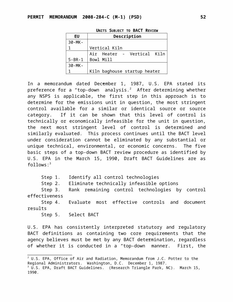
PERMIT MEMORANDUM 2008-284-C (M-1) (PSD) 52
(F-19)
007-BR-1 EF-12(P-2) Flash Furnace
10
007-FS-2 EF-16(P-2) West Truck Loading Bin
007-FS-1 EF-18(P-2) East Rail and Truck Loading Bin
007-LS-2 EF-19(P-2) West Loading Chute – MC-3413
007-LS-1 EF-20(P-2) East Loading Chute – MC-3395
007-BM-1 EF-8(P-2) Raymond Mill / Whizzer Classifier
Emissions from the existing Fines Department equipment are vented through a baghouse (Equipment 007-DC-1) designated as point “P-2.” This baghouse/capture system is subject to the existing Subpart OOO emission limit of 0.05 g/DSCM (0.022 gr/DSCF).
Subpart IIII (Stationary Compression Ignition Internal Combustion Engines) affects stationary compression ignition (CI) internal combustion engines (ICE) that were ordered, modified, or reconstructed after July 11, 2005. Since the emergency engine for the KVS Kiln pre-dates Subpart IIII, Subpart IIII does not apply to the KVS Kiln emergency engine. Since the emergency generator engine for the Vertical Kiln has not been selected yet, the applicability of Subpart IIII to this engine has yet to be determined.
NESHAP, 40 CFR Part 61 [Not Applicable]There are no emissions of any of the pollutants subject to 40 CFR 61.
NESHAP, 40 CFR Part 63 [Applicable]Subpart AAAAA (NESHAP for Lime Manufacturing Plants). Subpart AAAAA only affects major sources of HAP. Stack testing has documented that the Marble City facility is an area source of HAPs.
Subpart ZZZZ (NESHAP for Reciprocating Internal Combustion Engines [RICE]). Owners and operators of existing emergency stationary RICE located at an area source of HAP emissions must meet the requirements of Subpart ZZZZ. The existing emergency diesel engine (KVS) is subject to Subpart ZZZZ. Since the emergency generator engine for the Vertical Kiln has not been selected yet, the specific applicability of Subpart ZZZZ to this engine has yet to be determined.
Subpart CCCCCC (NESHAP for Gasoline Dispensing Facilities). Owners and operators of gasoline dispensing facilities (GDF) located at area sources of HAP must meet certain work practice standards for the storage and dispensing of gasoline into motor vehicles, nonroad vehicles, lawn equipment, test engines, generators, pumps, and other gasoline-fueled engines and equipment. The 2000-gallon gasoline tank located at U.S. Lime and the associated dispensing of gasoline (EUG 18) are subject to this NESHAP. Since the monthly gasoline throughput is less than 10,000 gallons per month, only the Section 63.11116 proper housekeeping standards apply.
PERMIT MEMORANDUM 2008-284-C (M-1) (PSD) 53
Compliance Assurance Monitoring, 40 CFR Part 64 [Applicable]Compliance Assurance Monitoring (CAM) applies to any pollutant-specific emission unit at a major source that is required to obtain a Title V permit, if it meets all of the following criteria:
It is subject to an emission limit or standard for an applicable regulated air pollutant. It uses a control device to achieve compliance with the applicable emission limit or
standard. It has potential emissions, prior to the control device, of the applicable regulated air
pollutant of greater than 100 TPY.
The Vertical Kiln will be subject to CAM for SO2 and PM10 emissions which will be controlled by a baghouse. The kiln does not use an active control device to reduce NOx and CO emissions, therefore these pollutants are not subject to CAM. SO2 emissions are controlled by dry scrubbing of the SO2 with the lime dust present in the kiln and in the baghouse. U.S. Lime expects to use monitor pressure differential across the baghouse as an indicator of effective baghouse operation. CAM provisions for the kiln are incorporated into the permit Specific Conditions.
Chemical Accident Prevention Provisions, 40 CFR Part 68 [Not Applicable]This facility does not store any of the listed substances above the applicable threshold limits. Therefore, the Accidental Release Prevention provisions are not applicable to this facility. More information on this federal program is available on the web page: www.epa.gov/ceppo.
Stratospheric Ozone Protection, 40 CFR Part 82 [Not Applicable]These standards require phase out of Class I & II substances, reductions of emissions of Class I & II substances to the lowest achievable level in all use sectors, and banning use of nonessential products containing ozone-depleting substances (Subparts A & C); control servicing of motor vehicle air conditioners (Subpart B); require Federal agencies to adopt procurement regulations which meet phase out requirements and which maximize the substitution of safe alternatives to Class I and Class II substances (Subpart D); require warning labels on products made with or containing Class I or II substances (Subpart E); maximize the use of recycling and recovery upon disposal (Subpart F); require producers to identify substitutes for ozone-depleting compounds under the Significant New Alternatives Program (Subpart G); and reduce the emissions of halons (Subpart H).
SECTION VIII. OKLAHOMA AIR POLLUTION CONTROL RULES
OAC 252:100-1 (General Provisions) [Applicable]Subchapter 1 includes definitions but there are no regulatory requirements.
OAC 252:100-2 (Incorporation by Reference) [Applicable]This subchapter incorporates by reference applicable provisions of Title 40 of the Code of Federal Regulations. These requirements are addressed in the “Federal Regulations” section.
OAC 252:100-3 (Air Quality Standards and Increments) [Applicable]Subchapter 3 enumerates the primary and secondary ambient air quality standards and the significant
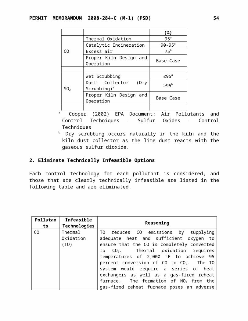
PERMIT MEMORANDUM 2008-284-C (M-1) (PSD) 54
deterioration increments. The primary standards are enumerated in Appendix E, and the secondary standards are enumerated in Appendix F of the Air Pollution Control Rules (OAC 252:100). National Ambient Air Quality Standards (NAAQS) are established by the U.S. EPA. The actual ambient air concentrations of criteria pollutants are monitored within the State of Oklahoma by the DEQ Air Quality Division. At this time, all of Oklahoma is in "attainment" of these standards. This construction project is not expected to cause or contribute to a violation of the NAAQS.
OAC 252:100-5 (Registration, Emission Inventory, and Annual Fees) [Applicable]The owner or operator of any facility that is a source of air emissions shall submit a complete emission inventory annually on forms obtained from the Air Quality Division. An emission inventory was submitted and fees paid for previous years as required.
OAC 252:100-7 (Permits for Minor Sources) [Not Applicable]The facility is a Part 70 source; therefore requirements of Subchapter 8 are applicable instead of Subchapter 7.
OAC 252:100-8 (Permits for Part 70 Sources) [Applicable]Part 5 includes the general administrative requirements for part 70 permits. Any planned changes in the operation of the facility which result in emissions not authorized in the permit and which exceed the “Insignificant Activities” or “Trivial Activities” thresholds require prior notification to AQD and may require a permit modification. Insignificant activities mean individual emission units that either are on the list in Appendix I (OAC 252:100) or whose actual calendar year emissions do not exceed the following limits:
5 TPY of any one criteria pollutant 2 TPY of any one hazardous air pollutant (HAP) or 5 TPY of multiple HAPs or 20%
of any threshold less than 10 TPY for single HAP that the EPA may establish by rule
OAC 252:100-9 (Excess Emissions Reporting Requirements) [Applicable]Except as provided in OAC 252:100-9-7(a)(1), the owner or operator of a source of excess emissions shall notify the Director as soon as possible but no later than 4:30 p.m. the following working day of the first occurrence of excess emissions in each excess emission event. No later than thirty (30) calendar days after the start of any excess emission event, the owner or operator of an air contaminant source from which excess emissions have occurred shall submit a report for each excess emission event describing the extent of the event and the actions taken by the owner or operator of the facility in response to this event. Request for affirmative defense, as described in OAC 252:100-9-8 shall be included in the excess emission event report. Additional reporting may be required in the case of ongoing emission events and in the case of excess emissions reporting required by 40 CFR Parts 60, 61, or 63.
OAC 252:100-13 (Open Burning) [Applicable]Open burning of refuse and other combustible material is prohibited except as authorized in the specific examples and under the conditions listed in this Subchapter. Open burning is not performed at the facility.
OAC 252:100-19 (Particulate Matter) [Applicable]This subchapter limits emissions of particulate matter from fuel-burning units. Section 252:100-
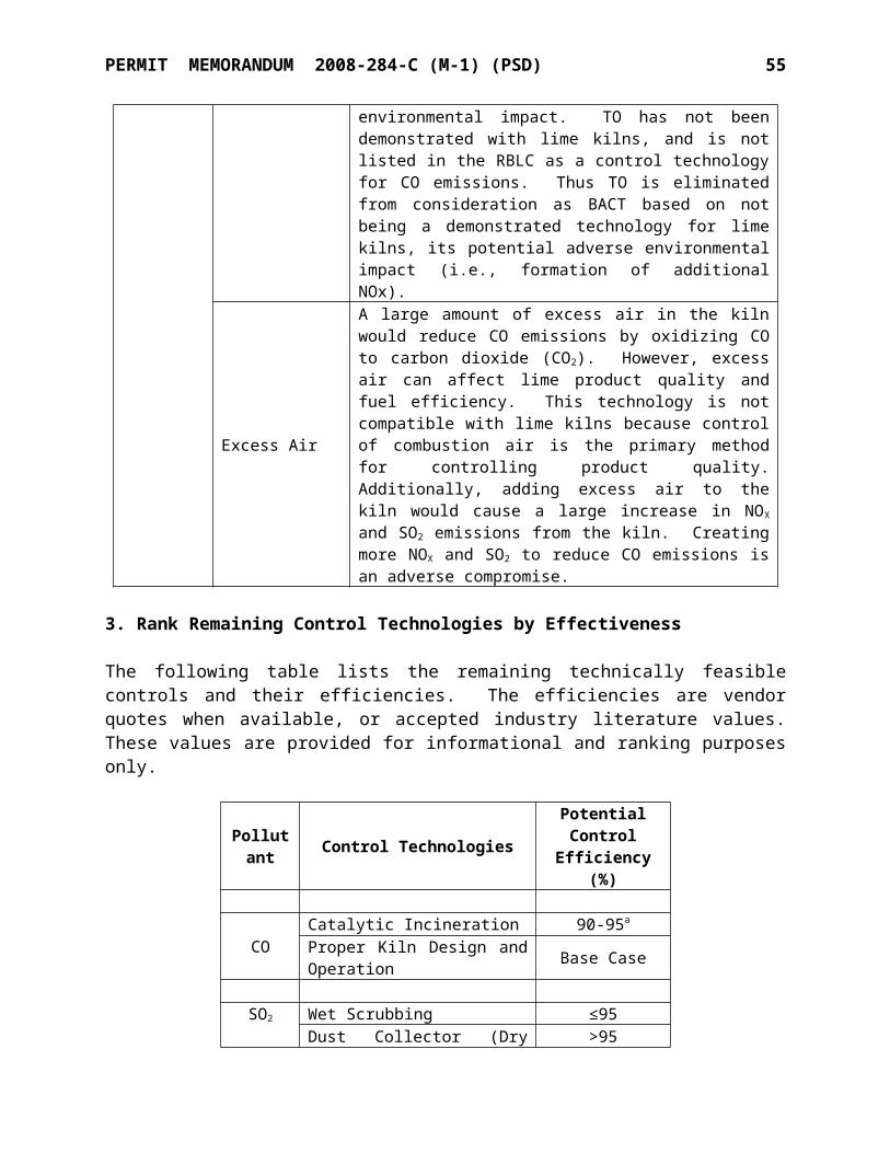
PERMIT MEMORANDUM 2008-284-C (M-1) (PSD) 55
19-4 establishes allowable particulate matter emission rates from indirect fired fuel-burning units (such as the gas-fired heaters in the PLS plant) via reference to Chapter 100, Appendix C. Natural gas-fired heaters have particulate matter emissions well below the allowable rates in Appendix C.
Section 252:100-19-12 establishes allowable particulate matter emission rates from directly fired fuel-burning units and industrial processes (such as the lime kilns) via reference to Chapter 100, Appendix G. For directly fired fuel-burning units and industrial processes, Appendix G specifies that the allowable total particulate matter emission rate for process weight rates greater than 30 tons per hour (60,000 lb/hr) is calculated using the formula:
E (lb/hr) = (55.00P0.11)-40
Where:E = allowable total particulate matter emission rate in pounds per hour andP = process weight rate in tons per hour.
EU Point DescriptionProcess
Rate
ActualPM
Emissions
AllowablePM
EmissionsTPH lb/hr lb/hr
EUG 1 8-CR-1/
- Crusher, hopper & grizzly 554.0 1.33 70.198-DH-1/8-SF-14-SN-1 - Screen 2 Deck 120.0 0.09 53.138-VBF-1 - Vibrating Feeder 435.8 0.10 67.328-CR-2 - Secondary Crusher 435.8 1.05 67.324-VBF-1 - Vibrating Feeders (9) 404.6 0.10 66.454-SN-3 - Roller Screen – Vertical Kiln Feed 82.3 0.06 49.348-MT-2 - Material Transfer (Stone) 435.8 0.58 67.328-SN-1/2 - Primary/Secondary Screens 989.8 1.04 77.46
8-MT-1 - Material Transfer (Stone) 989.8 1.99 77.46EUG 3 7-FB-1 - 100 Ton Fines Storage (PLS Feed) Bin 25.0 0.04 35.437-BR-1 7-DC-1 Flash Furnace 25.0 2.31 35.437-FS-2 Storage/Loading Bin - West - Roller Mill 25.0 35.437-FS-1 Storage/Loading Bin - East - Roller Mill 25.0 35.437-LS-2 Loading Spout - Truck Loading - West 125.0 53.55
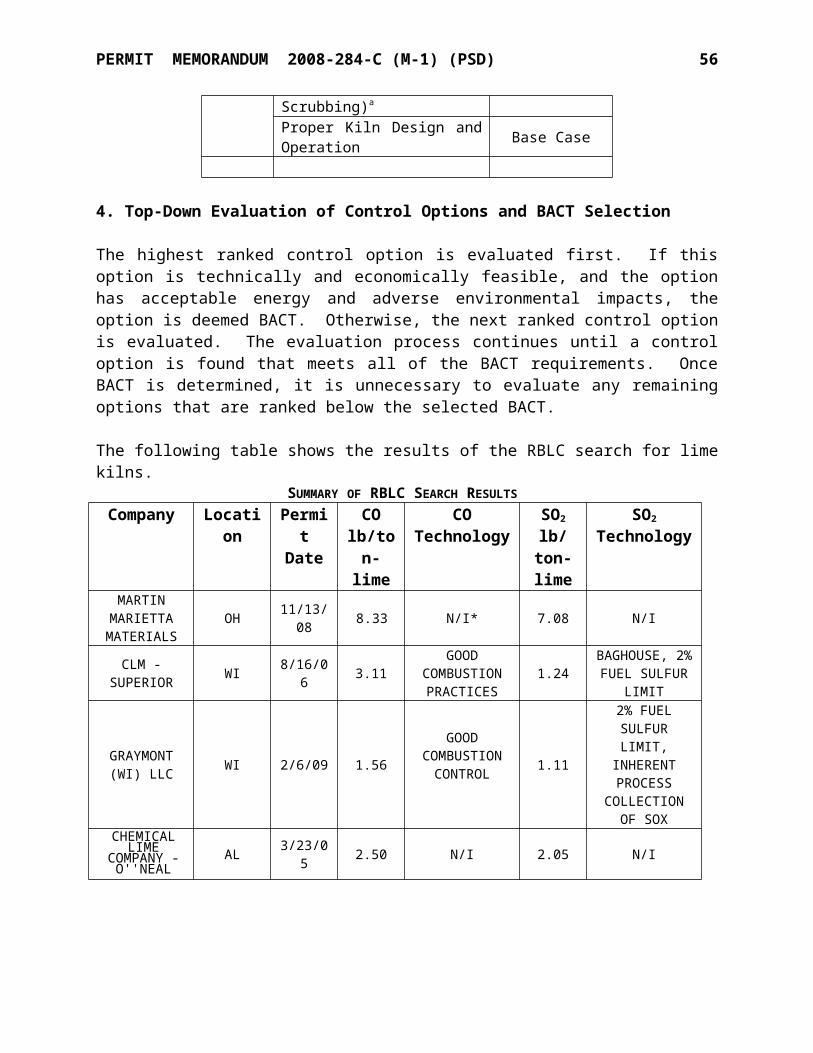
PERMIT MEMORANDUM 2008-284-C (M-1) (PSD) 56
EU Point DescriptionProcess
Rate
ActualPM
Emissions
AllowablePM
EmissionsTPH lb/hr lb/hr
7-LS-1 Loading Spout - Truck Loading - East 125.0 53.557-LS-3 Loading Spout - Rail Loading 150.0 55.447-BM-1/ Raymond Mill / Whizzer Classifier 25.0 35.437-WZ-17-SIFTER Rotary Screen No. 40M 24.0 34.487-MT-1 - Material Transfer (PLS) 150.0 0.01 55.44EUG 4
30-VBF-1 3-DC-5 Vibrating Feeders (2) 12.5
Emissions from 3-
DC-5 are included in EUG
16
Emissions from 3-
DC-5 are included in EUG
165-SF-3 5-DC-1 Solid Fuel Weigh Feeder (Vertical Kiln) 7.0 1.05 15.105-CS-3 Storage Bin - Pulverized Solid Fuel 7.0 15.1030-BR-1 30-DC-1 Inline startup heater - 6.84 -30-MK-1 30-DC-1 Vertical Kilna 80.0 49.06
30-LS-1 30-DC-4 Loading Spout – Vertical Kiln LKD/ 25.0 0.06 35.43Waste Loading30-MT-2 - Material Transfer (Stone) 80.0 0.001 49.06EK-12/ P-5 KVS Rotary Kiln with Bowl Mill classifiera 25.0 14 38.225-CL-130-DS-1 30-DC-3 LKD/Waste Bin - Vertical Kiln - North 4.3 0.12 10.8930-DS-2 30-DC-3 LKD/Waste Bin - Vertical Kiln - South 4.3 10.891-VBF-1 - Vibrating Feeders (4) 3.2 0.03 8.9430-MT-1 - Material Transfer (Stone) 3.2 0.01 8.945-MT-1 - Material Transfer (Coal/coke) 75.0 1.04 48.43EUG 5 EK-8 F-41 KVS Kiln Stone Bin 119.5 0.04 35.433-SN-1B
3-DC-1
Quicklime Screen 25.4Emissions
from 3-DC-1 are included in EUG
16
Emissions from 3-
DC-1 are included in EUG
16
3-QS-1 Quicklime Bin #1 - KVS ROK/Vertical Kiln 6.7
3-QS-2 Quicklime Bin #2 - KVS Jumbo Pebble 1.83-QS-3 Quicklime Bin #3 - KVS Jumbo Pebble 1.83-QS-4 Quicklime Bin #4 - KVS Jumbo Pebble 1.83-QS-5 Quicklime Bin #5 - KVS Sm. Pebble 8.93-QS-6 Quicklime Bin #6 - KVS Sm. Pebble 8.93-QS-7 3-DC-7 Quicklime Bin #7 - Dolomitic Lime 25.0 0.2 35.433-QS-8 Quicklime Bin #8 - KVS Sm. Pebble 8.9 17.743-CR-1 - Roll Crusher - KVS Oversize 6.7 0.002 14.663-SN-3 - Screen - Lime Recycle Scalping 100.0 0.72 51.283-MT-2 - Material Transfer (Stone) 120.0 0.03 53.13EUG 6 6-SC-3 - Hydrator clean-out screw conveyor 0.05 0.1 0.55EUG 7
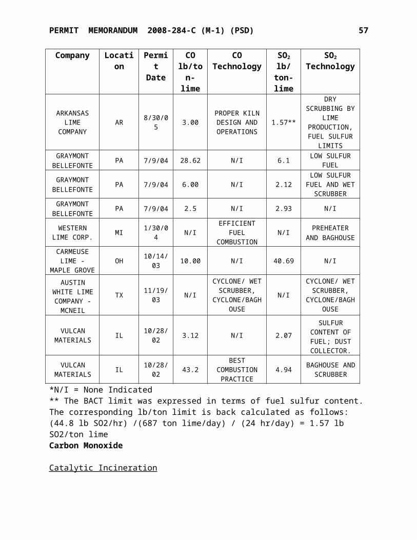
PERMIT MEMORANDUM 2008-284-C (M-1) (PSD) 57
EU Point DescriptionProcess
Rate
ActualPM
Emissions
AllowablePM
EmissionsTPH lb/hr lb/hr
6-QLS-1 6-DC-2 25-Ton Hydrate Feed Bin 16.0 1.13 26.286-WS-1 - Hydrator 16.0 3.84 26.286-WZ-1 - Whizzer Classifier - Hydrate 16.0 26.286-HS-1 6-DC-1 Hydrate Bin - East
16.0 0.4 26.286-HS-2 6-DC-1 Hydrate Bin - West6-LS-2 6-DC-1 Loading Spout - West Hydrate Bin6-LS-1 6-DC-1 Loading Spout - East Hydrate Bin6-HB-1 6-DC-1 Hydrate BaggerEUG 8 8-PILE-5 - Vertical Kiln Feed Pile 261.0 0.037 61.444-PILE-1 - KVS Fines Pile 0.5 0.001 2.584-PILE-2 - Vertical Kiln Fines Pile 2.3 0.001 7.168-PILE-3 - Small KVS Feed Pile 47.7 0.023 44.148-PILE-4 - Large KVS Feed Pile 99.2 0.029 51.207-PILE-1 - Fines plant stockpile 150.0 0.075 55.445-PILE-1 - Coal stockpile 200.0 0.130 58.515-PILE-2 - Coke stockpile 200.0 0.068 58.518-PILE-2 - Fines Plant Stockpile / Waste Pile 7.9 0.009 16.381-PILE-2 - Waste Pile 0.5 0.000 2.581-PILE-1 - Waste Pile 0.5 0.000 2.58
8-PILE-1 - Crusher screenings pile / Primary Surge Pile 435.8 0.066 67.32
3-PILE-1 - Oversized Tramp Pile 0.1 0.001 0.88EUG 16 3-BQ-1
3-DC-3
Briquetter #1 5.0
0.9
12.053-BQ-2 Briquetter #2 5.0 12.05
3-BC-30 Belt Conveyor - Bin #12 & 13 To Loadout Transfer 100.0 51.28
3-BC-31 Belt Conveyor - Loadout Transfer 100.0 51.283-SN-7 / 3-DC-5 Vertical Kiln Scalping and 26.5 0.78 36.843-SN-8 4-Deck Screens3-CR-2 Roll Crusher - Vertical Kiln Lime 9.3 18.273-QS-17 Lime Bin #17 - Vertical Kiln ROK 9.3 18.273-QS-18 Lime Bin #18 - Vertical Kiln ROK 11.0 20.443-LS-10 3-DC-10 Loading Spout - Lime Bin #10 50.0 0.06 44.583-BC-33
3-DC-30
Belt Conveyor - Lime Transfer to Loadout
100.0 0.12 51.283-BC-34 Belt Conveyor - Lime Transfer to Loadout 3-BC-36 Belt Conveyor - Loadout 3-VBF-26 Vibrating Feeders (2)3-LS-30 Loading Spout - Quicklime To Truck 3-VBF-27
3-DC-31
Vibrating Feeder
100.0 0.12 51.283-BC-32 Belt Conveyor - Loadout Transfer 3-BC-35 Belt Conveyor - Lime Loadout 3-LS-31 Loading Spout - Quicklime To Rail 3-VBF-29 - Vibrating Feeders (5) - Enclosed 100.0 0.08 51.28
PERMIT MEMORANDUM 2008-284-C (M-1) (PSD) 58
EU Point DescriptionProcess
Rate
ActualPM
Emissions
AllowablePM
EmissionsTPH lb/hr lb/hr
3-SN-6
3-DC-1
Static Grizzly 12.5
1.28
22.27
3-QS-9 Quicklime Bin #9 - Vertical Kiln Lg. Pebble 14.4 24.48
3-QS-10 Bin #10 - Waste Lime 0.25 1.62
3-QS-11 Quicklime Bin #11 - Vertical Kiln Lg. Pebble 14.4 24.48
3-QS-14 Quicklime Bin #14 - KVS Fines 4.4 11.06
3-QS-15 Quicklime Bin #15 - Vertical Kiln /KVS Fines 9.4 18.40
3-QS-12 3-DC-2Quicklime Bin #12 - Vertical Kiln Sm. Pebble 16.4 0.78 26.71
3-QS-16 Quicklime Bin #16 - Vertical Kiln Fines 9.4 18.407-VBF-3 - Vibrating Feeder 150.0 0.36 55.443-VBF-1 - Vibrating Feeders (9) - Enclosed 100.0 0.18 51.283-MT-1 - Material Transfer (Lime) 100.0 0.03 51.28a Process rate for the kilns is the limestone feed capacity of the kilns and not the lime production of the kilns.
OAC 252:100-25 (Visible Emissions and Particulates) [Applicable]No discharge of greater than 20% opacity is allowed except for short-term occurrences which consist of not more than one six-minute period in any consecutive 60 minutes, not to exceed three such periods in any consecutive 24 hours. In no case shall the average of any six-minute period exceed 60% opacity. Emission units subject to an NSPS opacity limit are exempt from this section. The new and modified equipment in this application are subject to opacity limits under NSPS and are exempt from this subchapter.
OAC 252:100-29 (Fugitive Dust) [Applicable]No person shall cause or permit the discharge of any visible fugitive dust emissions beyond the property line on which the emissions originate in such a manner as to damage or to interfere with the use of adjacent properties, or cause air quality standards to be exceeded, or interfere with the maintenance of air quality standards. Under normal operating conditions, the facility will not interfere with the maintenance of air quality standards. U.S. Lime will employ best management practices to minimize particulate emissions from roads and other industrial activities.
OAC 252:100-31 (Sulfur Compounds) [Applicable]Part 5 limits sulfur dioxide emissions from new equipment (constructed after July 1, 1972). For gaseous fuels the stack emissions limit is 0.2 lb/MMBTU heat input, three-hour average. AP-42 (3/98) Table 1.4-2 lists SO2 emissions as 0.6 lb/MMSCF or about 0.0006 lb/MMBTU, which is in compliance with the 0.2 lb/MMBTU limitation. For solid fuels, the stack emissions limit is 1.2 lb SO2/MMBTU heat input, three-hour average. The Vertical Kiln SO2 BACT emissions limit (0.868 lb/ton) corresponds to approximately 0.22 lb/MMBtu, well below the 1.2 lb/MMBtu limit. The permit also requires that all fuels be tested or have a certified analysis showing the sulfur content.
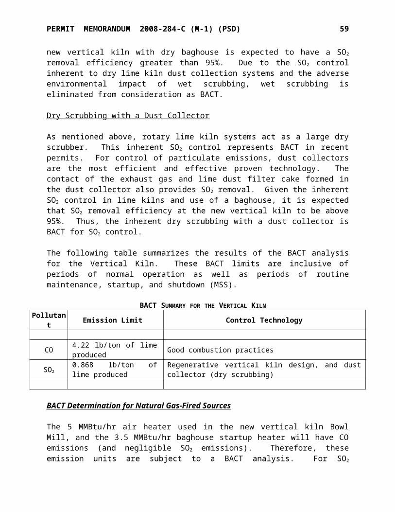
PERMIT MEMORANDUM 2008-284-C (M-1) (PSD) 59
OAC 252:100-33 (Nitrogen Oxides) [Applicable]This subchapter affects NOX emissions from new fuel-burning equipment with a rated heat input of 50 MMBTUH or more, thus NOX emissions are limited to 0.7 lb/MMBTU, expressed as NO2.
OAC 252:100-35 (Carbon Monoxide) [Not Applicable]None of the following affected processes are part of this project: gray iron cupola, blast furnace, basic oxygen furnace, petroleum catalytic cracking unit or catalytic reforming unit.
OAC 252:100-37 (Volatile Organic Compounds) [Applicable]Part 3 requires storage tanks constructed after December 28, 1974, with a capacity of 400 gallons or more and storing a VOC with a vapor pressure greater than 1.5 psia to be equipped with a permanent submerged fill pipe or with an organic vapor recovery system.Part 5 limits the VOC content of coating used in coating lines or operations. This facility will not normally conduct coating or painting operations except for routine maintenance of the facility and equipment, which is exempt. Part 7 requires fuel-burning equipment to be operated and maintained so as to minimize VOC emissions. Temperature and available air must be sufficient to provide essentially complete combustion. The kilns and dryer are designed to provide essentially complete combustion of organic materials.
OAC 252:100-42 (Toxic Air Contaminants (TAC)) [Not Applicable]All parts of OAC 252:100-41, with the exception of Part 3, has been superseded by this subchapter. Subchapter 42 allows the Director to designate a geographic region in Oklahoma as an Area of Concern (AOC) if ambient concentrations of toxic air contaminants have exceeded a Maximum Acceptable Ambient Concentration (MAAC). When an AOC has been designated, the agency has the authority to establish monitoring sites and develop AOC compliance strategies, if necessary. At present, Sequoyah County is not part of any geographic region that has been designated as an AOC.
OAC 252:100-43 (Testing, Monitoring, and Recordkeeping) [Applicable]This subchapter provides general requirements for testing, monitoring and recordkeeping and applies to any testing, monitoring or recordkeeping activity conducted at any stationary source. To determine compliance with emissions limitations or standards, the Air Quality Director may require the owner or operator of any source in the state of Oklahoma to install, maintain and operate monitoring equipment or to conduct tests, including stack tests, of the air contaminant source. All required testing must be conducted by methods approved by the Air Quality Director and under the direction of qualified personnel. A notice-of-intent to test and a testing protocol shall be submitted to Air Quality at least 30 days prior to any EPA Reference Method stack tests. Emissions and other data required to demonstrate compliance with any federal or state emission limit or standard, or any requirement set forth in a valid permit shall be recorded, maintained, and submitted as required by this subchapter, an applicable rule, or permit requirement. Data from any required testing or monitoring not conducted in accordance with the provisions of this subchapter shall be considered invalid. Nothing shall preclude the use, including the exclusive use, of any credible evidence or information relevant to whether a source would have been in compliance with applicable requirements if the appropriate performance or compliance test or procedure had been performed.
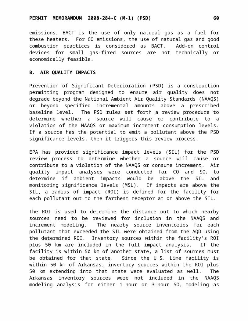
PERMIT MEMORANDUM 2008-284-C (M-1) (PSD) 60
The following Oklahoma Air Pollution Control Rules are not applicable to this facility:OAC 252:100-8 Part 9 Major Sources Affecting Nonattainment Areas not in area categoryOAC 252:100-15 Mobile Sources not in source categoryOAC 252:100-17 Incinerators not type of emission unitOAC 252:100-23 Cotton Gins not type of emission unitOAC 252:100-24 Grain Elevators not in source categoryOAC 252:100-29-2 Fugitive Dust/Nonattainment Areas not in area categoryOAC 252:100-39 Nonattainment Areas not in area categoryOAC 252:100-47 Landfills not in source category
SECTION IX. COMPLIANCE
Tier Classification and Public Review
This application has been determined to be Tier II based on being the request for a significant construction modification of a Part 70 operating permit.
The applicant published the “Notice of Filing a Tier II Application” on November 4, 2010, in the Sequoyah County Times, a semi-weekly newspaper in Sequoyah County. The notice stated that the application was available for review at the Stanley Tubbs Memorial Library, 101 E. Cherokee Avenue in Sallisaw and at the Oklahoma City office of the Air Quality Division.
The applicant published the “Notice of Tier II Draft Permit” on September 25, 2013, in the Sequoyah County Times, a semi-weekly newspaper in Sequoyah County. The notice stated that the Draft Permit was available for review at the Stanley Tubbs Memorial Library, 101 E. Cherokee Avenue in Sallisaw and at the Oklahoma City office of the Air Quality Division.
EPA review ran concurrently with public notice. The 45 day EPA review period started on September 13, 2013 and ended on October 28, 2013.
This facility is located within 50 miles of the border of Oklahoma and the state of Arkansas; that state will be notified of the draft permit.
Information on all permit actions is available on the DEQ web page: www.deq.state.ok.us.
Comments From the state of ArkansasThere were no comments received from the state of Arkansas.
Comments From PublicThere were no comments received from the public.
Comments From EPAThere were no comments received from the EPA.
Comments From Applicant
PERMIT MEMORANDUM 2008-284-C (M-1) (PSD) 61
1. The Applicant identified minor manuscript errors. These errors were addressed and corrected.
2. The following request was made by the Applicant.a. Page 15, Specific Condition 3, item i. Since the Vertical Kiln pressure drop
monitoring is not required by this permit (but is likely pending per Condition 13 of EUG-4), record keeping for Vertical Kiln pressure differentials should be removed.
Comments From DEQ
DEQ agrees with the Applicant’s request to change minor manuscript errors.
As regarding #2 of the Applicant’s comments. Vertical Kiln pressure needs to be monitored daily in order to determine a normal operating pressure that can be used as CAM to ensure normal operation of the Vertical Kiln. Therefore, this Specific Condition language will remain in the permit.
Inspection
The facility was last inspected on June 7, 2011, by Ms. Brandie Czerwinski of the DEQ Tulsa Regional Office. It was verified that the facility existed as described in the permit application, and that required air pollution controls (baghouses and wet scrubbers) were present.
Fees Paid
Construction permit application fee of $1,500.
SECTION X. SUMMARY
The facility was constructed and is operating as described in the permit application. Ambient air quality standards are not threatened at this site. There are no active Air Quality enforcement issues which would affect issuance of this permit. Issuance of the permit is recommended.
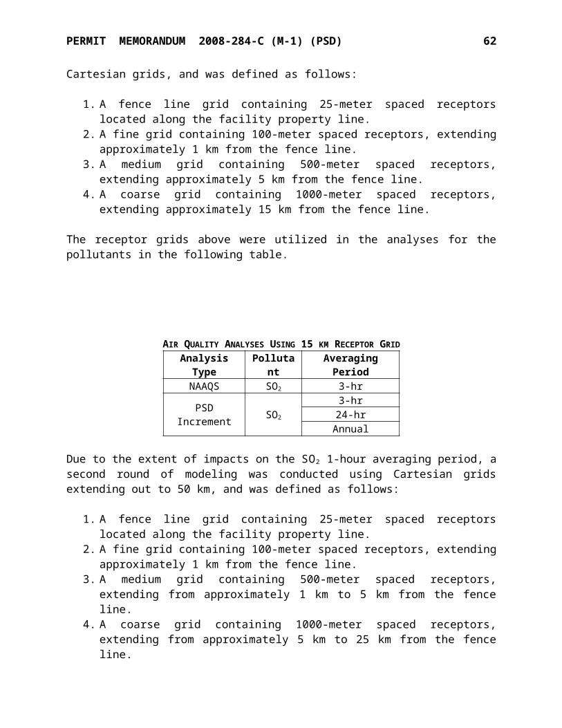
PERMIT TO CONSTRUCTAIR POLLUTION CONTROL FACILITY
SPECIFIC CONDITIONS
U. S. Lime & Minerals Company Permit No. 2008-284-C (M-1) (PSD)Marble City Plant
The permittee is authorized to construct in conformity with the specifications submitted to Air Quality on September 22, 2010, and supplemented on February 17, 2011; July 22, 2011; September 22, 2011; January 18, 2012; August 9, 2012; and October 10, 2012. The Evaluation Memorandum, dated November 1, 2013, explains the derivation of applicable permit requirements and estimates of emissions; however, it does not contain operating limitations or permit requirements. Commencing construction or operations under this permit constitutes acceptance of, and consent to, the conditions contained herein:
1. Emission limitations and points of emissions: [OAC 252:100-8-6(a)]
EUG-1A Crusher Department (Pre-2008 Subpart OOO Limits)EU Point Description Opacity Limit
8-CR-1 / 8-SF-1 / 8-SF-1 - Crusher, hopper & grizzly 15%8-SN-1 / 8-SN-2 - Primary/Secondary Screens 10%8-MT-1 - Material Transfer (Stone) -8-MT-1 8-SN-1 Primary screen transfer 10%8-MT-1 8-BC-1 Belt conveyor transfer 10%8-MT-1 8-BC-2 Belt conveyor transfer 10%8-MT-1 8-BC-5 Belt conveyor transfer 10%8-MT-1 8-SF-1 Vibrating grizzly feeder transfer 15%8-MT-1 8-SN-2 Secondary screen transfer 10%
EUG-1B Crusher Department (Post-2008 Subpart OOO Limits)
EU Point Description Opacity Limit
4-SN-1 - Screen 2 Deck 7%8-VBF-1 - Vibrating Feeder 7%8-CR-2 - Secondary Crusher 12%4-VBF-1 - Vibrating Feeders (9) 7%4-SN-3 - Roller Screen – Vertical Kiln Feed 7%8-MT-2 - Material Transfer (Stone) 7%8-MT-1 - Material Transfer (Stone) 7%8-MT-1 8-CR-2 Secondary crusher transfer 12%8-MT-1 8-BC-6 Belt conveyor transfer 7%8-MT-1 8-BC-7 Belt conveyor transfer 7%8-MT-1 8-BC-8 Belt conveyor transfer 7%8-MT-1 8-BC-10 Belt conveyor transfer 7%8-MT-1 4-SN-1 Screen transfer 7%8-MT-1 8-VBF-1 Vibrating feeder transfer 7%8-MT-1 8-BC-3A Belt conveyor transfer 7%30-MT-2 - Material Transfer (stone to Vertical Kiln) 7%
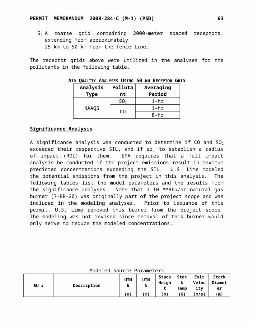
SPECIFIC CONDITIONS NO. 2008-284-C (M-1) (PSD) 2
1. The equipment in EUG 1A and 1B is subject to NSPS Subpart OOO and shall comply with all applicable requirements. Truck dumping of non-metallic minerals is not subject to the opacity standards of Subpart OOO. [40 CFR Part 63.670-676]
2. Wet suppression or foam suppression may be used at or upstream of crushers and screens when needed to limit the opacity of fugitive discharges.
3. The owner or operator of any affected facility for which construction, modification, or reconstruction commenced on or after April 22, 2008, that uses wet suppression to control emissions from the affected facility must perform monthly periodic inspections to check that water is flowing to discharge spray nozzles in the wet suppression system. The owner or operator must initiate corrective action within 24 hours and complete corrective action as expediently as practical if the owner or operator finds that water is not flowing properly during an inspection of the water spray nozzles. The owner or operator must record each inspection of the water spray nozzles, including the date of each inspection and any corrective actions taken, in the logbook required under §60.676(b).
[40 CFR 60.674(b)]4. The opacity of discharges from screens and conveyor transfer points constructed before
April 22, 2008 shall not exceed 10% opacity. The opacity of discharges from screens and conveyor transfer points constructed after April 22, 2008 shall not exceed 7% opacity.
[40 CFR 60.672(b)]5. The opacity of discharges from crushers constructed before April 22, 2008 shall not
exceed 15% opacity. The opacity of discharges from crushers constructed after April 22, 2008 shall not exceed 12% opacity. [40 CFR 60.672(b)]
6. Either no visible fugitive emissions shall be discharged from any building enclosing an affected facility, or opacity shall not exceed 10% from any pre-2008 affected facility and 7% from any post-2008 affected facility per 40 CFR 60.672(b). [40 CFR 60.672(e)(1)]
7. Reports shall be submitted as specified. [40 CFR 60.676]8. Compliance with opacity limitations shall be demonstrated as follows:
[OAC 252:100-8-6(a)]a. The permittee shall conduct Method 9 or Method 22 visual
observations of emissions from each point listed above at least once per week during which a unit operates. In no case shall the observation period be less than six minutes in duration. If visible emissions are observed for six minutes in duration for any observation period and such emissions are not the result of a malfunction, then the permittee shall conduct, for the identified points, within 24 hours, a visual observation of emissions, in accordance with 40 CFR Part 60, Appendix A, Method 9.
b. When four consecutive weekly visible emission observations or Method 9 observations show no visible emissions, or no emissions of a shade or density greater than twenty (20) percent equivalent opacity, respectively, the frequency may be reduced to monthly visual observations, as above. Upon any showing of non-compliance the observation frequency shall revert to weekly.
c. If a Method 9 observation exceeds 20% opacity the permittee shall conduct at least two additional Method 9 observations within the next 24-hours.
d. If more than one six-minute Method 9 observation exceeds 20% opacity in any consecutive 60 minutes; or more than three six-minute Method 9
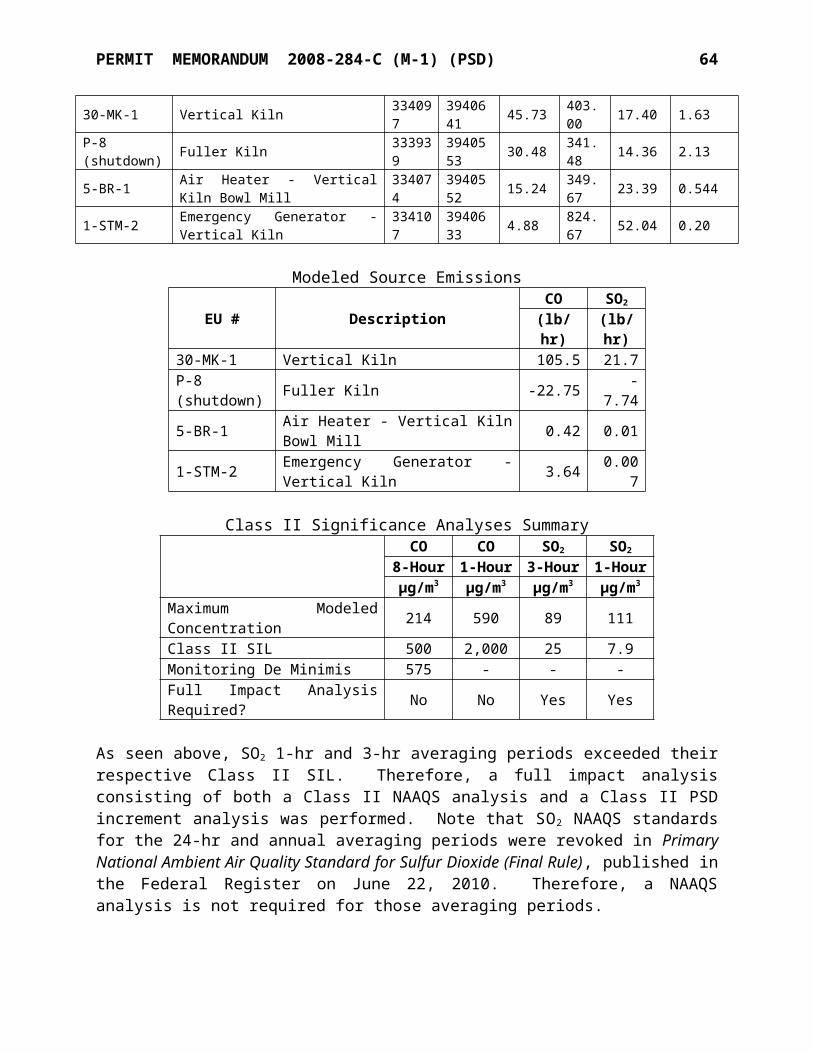
SPECIFIC CONDITIONS NO. 2008-284-C (M-1) (PSD) 3
observations in any consecutive 24 hours exceeds 20% opacity; or if any six-minute Method 9 observation exceeds 60% opacity; the owner or operator shall comply with the provisions for excess emissions during start-up, shut-down, and malfunction of air pollution control equipment.
EUG-3 Fines Department
EU Point Description PM10
lb/hr TPY7-BR-1
7-DC -1
Flash Furnace
2.31 10.08
7-FS-2 Storage/Loading Bin - West - Roller Mill7-FS-1 Storage/Loading Bin - East - Roller Mill7-LS-2 Loading Spout - Truck Loading - West7-LS-1 Loading Spout - Truck Loading - East7-LS-3 Loading Spout - Rail Loading7-BM-1 / 7-WZ-1 Raymond Mill / Whizzer Classifier7-SIFTER Rotary Screen No. 40M7-FB-1 - 100 Ton Fines Storage (PLS Feed) Bin 0.04 0.147-MT-1 - Material Transfer (PLS) 0.01 0.02
1. The equipment in EUG-3 is subject to NSPS Subpart OOO and shall comply with all applicable requirements. [40 CFR Part 63.670-676]
2. Either no visible fugitive emissions shall be discharged from any building enclosing an affected facility, or opacity shall not exceed 10% from any pre-2008 affected facility and 7% from any post-2008 affected facility per 40 CFR 60.672(b). [40 CFR 60.672(e)(1)]
3. Reports shall be submitted as specified. [40 CFR 60.676]4. Compliance with emissions limitations shall be demonstrated as follows:
[OAC 252:100-8-6(a)]a. Existing dust collector 7-DC-1 shall be operated at a pressure differential
of at least 1 inch WG and no more than 10 inches WG when the process is operating. At least once per operating day, the permittee shall record the pressure differential at 7-DC-1.
b. The permittee shall conduct Method 9 or Method 22 visual observations of emissions from each point listed above at least once per week during which a unit operates. In no case shall the observation period be less than six minutes in duration. If visible emissions are observed for six minutes in duration for any observation period and such emissions are not the result of a malfunction, then the permittee shall conduct, for the identified points, within 24 hours, a visual observation of emissions, in accordance with 40 CFR Part 60, Appendix A, Method 9.
c. When four consecutive weekly visible emission observations or Method 9 observations show no visible emissions, or no emissions of a shade or density greater than twenty (20) percent equivalent opacity, respectively, the frequency may be reduced to monthly visual observations, as above. Upon any showing of non-compliance the observation frequency shall revert to weekly.
d. If a Method 9 observation exceeds 20% opacity the permittee shall conduct at least two additional Method 9 observations within the next 24-hours.
e. If more than one six-minute Method 9 observation exceeds 20% opacity in any consecutive 60 minutes; or more than three six-minute Method 9 observations in any
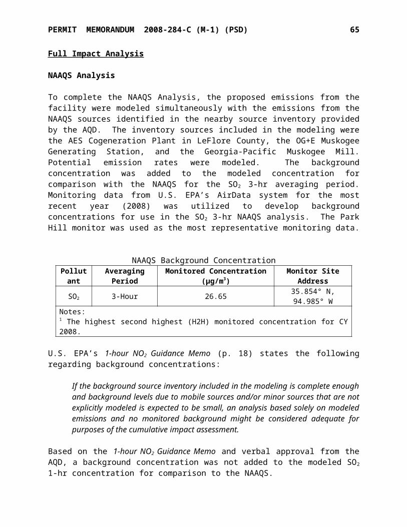
SPECIFIC CONDITIONS NO. 2008-284-C (M-1) (PSD) 4
consecutive 24 hours exceeds 20% opacity; or if any six-minute Method 9 observation exceeds 60% opacity; the owner or operator shall comply with the provisions for excess emissions during start-up, shut-down, and malfunction of air pollution control equipment. [OAC 252:100-25]
EUG-4 Kiln Department – Non-Grandfathered Equipment
EU Point Description PM10 PM2.5
lb/hr TPY lb/hr TPY30-VBF-1 3-DC-5 Vibrating Feeders (2) Emissions from 3-DC-5 are included
on EUG 16 Lime S&H5-SF-3 5-DC-1 Solid Fuel Weigh Feeder (Vertical Kiln) 1.05 4.57 0.10 0.455-CS-3 Storage Bin Pulverized Solid Fuel
30-LS-1 30-DC-4
Loading Spout - Vertical Kiln LKD/Waste Loading 0.07 0.28 0.01 0.03
30-MT-2 - Material Transfer (Stone) 0.001 0.002 0.0002 0.001
5-CL-1 5-CL-1 Bowl Mill Classifier (KVS) - - - -30-DS-1 30-DC-
3LKD/Waste Bin - Vertical Kiln North 0.12 0.51 0.01 0.0530-DS-2 LKD/Waste Bin - Vertical Kiln South
1-VBF-1 1-VBF-1 Vibrating Feeders (4) 0.03 0.12 0.03 0.12
30-MT-1 - Material Transfer (Stone) 0.01 0.06 0.001 0.015-MT-1 - Material Transfer (Coal/coke) 1.04 0.26 0.16 0.045-BR-1 5-DC-1 Air Heater - Vertical Kiln Coal Mill 0.04 0.18 0.04 0.18
30-BR-1 30-DC-1 Inline startup heater included in Vertical Kiln emissions
below30-MK-1
30-DC-1 Vertical Kiln and coal mill 6.84 29.93 6.21 27.21
EK-12 P-5 KVS Rotary Kiln and coal mill8 38.22
167.40 - -
Point Description CO NOX SO2
lb/hr TPY lb/hr TPY lb/hr TPY
5-DC-1 Air Heater - Vertical Kiln Bowl Mill 0.42 1.84 0.50 2.19 0.01 0.05
30-DC-1 Inline startup heater included in kiln emissions below
30-DC-1 Vertical Kiln 105.50 443.61 55.00 231.26 21.7 91.2
P-5 Rotary Kiln (KVS) * * 55.30 242.21 9.3 40.7
* The KVS Rotary Kiln is an existing unit and has no applicable CO emission limits.
EU Point Description Opacity Limit30-VBF-1 3-DC-5 Vibrating Feeders (2) 20%5-SF-3 5-DC-1 Solid Fuel Weigh Feeder (Vertical Kiln) 20%5-CS-3 Storage Bin - Pulverized Solid Fuel 20%5-BR-1 5-DC-1 Air Heater - Vertical Kiln Bowl Mill 20%30-BR-1 30-DC-1 Inline startup heater 20%30-MK-1 30-DC-1 Vertical Kiln 20%EK-12 P-5 KVS Kiln 20%
8 The listed particulate emission rates for the KVS Rotary Kiln are for total PM, not PM10.
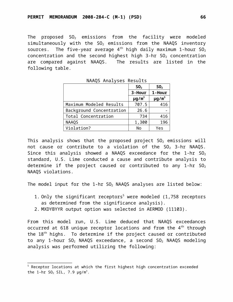
SPECIFIC CONDITIONS NO. 2008-284-C (M-1) (PSD) 5
30-LS-1 30-DC-4 Loading Spout – Vertical Kiln LKD/Waste Loading 20%5-CL-1 5-CL-1 Bowl Mill Classifier (KVS) 20%30-DS-1 30-DC-3 LKD/Waste Bin - Vertical Kiln - North 20%30-DS-2 LKD/Waste Bin - Vertical Kiln - South1-VBF-1 1-VBF-1 Vibrating Feeders (4) 20%30-MT-1 - Material Transfer (Stone) 20%5-MT-1 - Material Transfer (Coal/coke) 20%
1. NOX emissions from the Kilns shall not exceed 0.7 lb/MMBTU from solid fuel combustion or 0.2 lb/MMBTU from gas fuel combustion. [OAC 252:100-33]
2. The Vertical Kiln and KVS Kiln may be fueled with natural gas, petroleum coke or coal. Sulfur content of solids fuels or fuel blends shall not exceed 6.0% by weight. SO2
emissions shall not exceed 1.2 lb/MMBTU. The permittee may petition for a higher fuel sulfur content limit if performance testing shows that scrubbing system SO2 removal rates are sufficient to maintain compliance with SO2 emission limits. [OAC 252:100-31]
3. Exhaust gases from the Vertical Kiln shall be vented through the fabric filter dust collector (30-DC-1) at all times.
4. The permittee shall not produce more than 210,240 tons of lime from the Vertical Kiln on a rolling 12-month basis. Monthly and rolling 12-months records of lime production must be kept.
5. SO2 emissions from the Vertical Kiln shall not exceed 0.868 lbs per ton of lime produced on a rolling 30-day average basis, including during periods of routine maintenance, startup, or shutdown.a. The permittee shall maintain daily records of the amount of lime produced each
operating day and for each rolling 30-day period.b. The permittee shall measure and record the amount of solid fuel combusted each
operating day.c. The permittee shall determine and record the sulfur (S) content of the solid fuel blend
each operating day.d. The permittee shall calculate daily SO2 emissions based on the following equation:
i. lb SO2/day = (Tons solid fuel/day) x (2000 lb/ton) x (lb S/lb Fuel) x (64 lb/lbmol SO2/32 lb/lbmol S) x (lbmol SO2/lbmol S) x (100 - % SO2 removal efficiency).
ii. The % SO2 removal efficiency shall be based on the testing as described in Condition 11.
e. The permittee shall determine and record the lb of SO2 emissions per ton of lime produced for each operating day and for each rolling 30-day averaging period.
f. For purposes of this Condition, SO 2 emissions from the combustion of pipeline quality natural gas are assumed to be negligible and no calculations for natural gas combustion are necessary.
6. SO2 emissions from the Vertical Kiln and KVS Kiln shall not exceed 21.7 lb/hr and 9.3 lb/hr, respectively, based on a 30-day rolling average.a. The permittee shall monitor and record the hours of operation for each Kiln.b. The permittee shall determine the daily-average hourly SO2 emission rate from each
Kiln using the equation in Condition 5.d, and dividing by the daily operating hours for each kiln.
c. Using the daily-average hourly emission rate calculated above for each Kiln, the permittee shall determine and record a 30-day rolling average emission rate for each
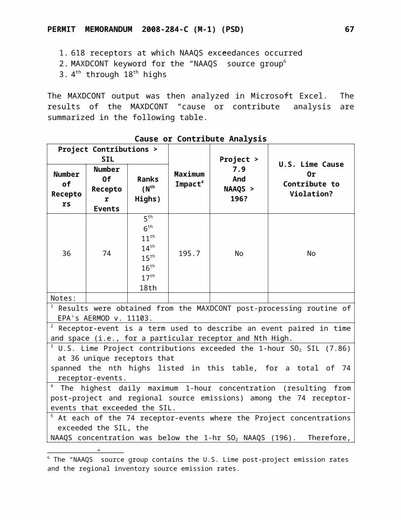
SPECIFIC CONDITIONS NO. 2008-284-C (M-1) (PSD) 6
operating day for each Kiln.7. CO emissions from the Vertical Kiln shall not exceed 4.22 lbs per ton of lime produced,
including periods of routine maintenance, startup, or shutdown. Compliance shall be demonstrated via the testing required by Condition 11.
8. No discharge of greater than 20% opacity is allowed except for short-term occurrences which consist of not more than one six-minute period in any consecutive 60 minutes, not to exceed three such periods in any consecutive 24 hours. In no case shall the average of any six-minute period exceed 60% opacity.
9. For the Vertical Kiln dust collector (30-DC-1), compliance with opacity limitations shall be demonstrated as follows: [OAC 252:100-8-6(a)]a. The permittee shall conduct Method 9 or Method 22 visual observations of emissions
from the Vertical Kiln dust collector (30-DC-1) at least once per day during which the vertical kiln operates. In no case shall the observation period be less than six minutes in duration. If visible emissions are observed for six minutes in duration for any observation period and such emissions are not the result of a malfunction, then the permittee shall conduct, for the identified points, within 24 hours, a visual observation of emissions, in accordance with 40 CFR Part 60, Appendix A, Method 9.
b. If a Method 9 observation exceeds 20% opacity the permittee shall conduct at least two additional Method 9 observations within the next 24-hours.
c. If more than one six-minute Method 9 observation exceeds 20% opacity in any consecutive 60 minutes; or more than three six-minute Method 9 observations in any consecutive 24 hours exceeds 20% opacity; or if any six-minute Method 9 observation exceeds 60% opacity; the owner or operator shall comply with the provisions of OAC 252:100-9.
d. The permittee shall maintain a log of all VE surveys, survey results, and corrective actions implemented.
e. The permittee shall submit with the operating permit application, a method of monitoring the Vertical Kiln dust collector (30-DC-1) to ensure compliance with the PM10 limits in specific condition #1.
10. For all other dust collectors in this EUG – 3-DC-5, 5-DC-1, 30-DC-4, and 30-DC-3, compliance with opacity limitations shall be demonstrated as follows:
[OAC 252:100-8-6(a)]d. The permittee shall conduct Method 9 or Method 22 visual observations of emissions
from each point listed above at least once per week during which a unit operates. In no case shall the observation period be less than six minutes in duration. If visible emissions are observed for six minutes in duration for any observation period and such emissions are not the result of a malfunction, then the permittee shall conduct, for the identified points, within 24 hours, a visual observation of emissions, in accordance with 40 CFR Part 60, Appendix A, Method 9.
e. When four consecutive weekly visible emission observations or Method 9 observations show no visible emissions, or no emissions of a shade or density greater than twenty (20) percent equivalent opacity, respectively, the frequency may be reduced to monthly visual observations, as above. Upon any showing of non-compliance the observation frequency shall revert to weekly.
f. If a Method 9 observation exceeds 20% opacity the permittee shall conduct at least
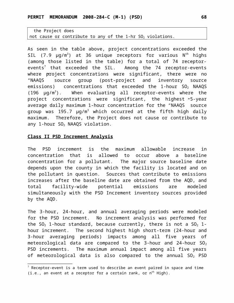
SPECIFIC CONDITIONS NO. 2008-284-C (M-1) (PSD) 7
two additional Method 9 observations within the next 24-hours.g. If more than one six-minute Method 9 observation exceeds 20% opacity in any
consecutive 60 minutes; or more than three six-minute Method 9 observations in any consecutive 24 hours exceeds 20% opacity; or if any six-minute Method 9 observation exceeds 60% opacity; the owner or operator shall comply with the provisions for excess emissions during start-up, shut-down, and malfunction of air pollution control equipment.
11. The permittee shall conduct performance testing on the Vertical Kiln and KVS Kiln as shown in the Table below and furnish a written report to Air Quality. Initial testing shall be completed within 180 days of Vertical Kiln startup. Testing shall be conducted while the Vertical Kiln is combusting solid fuel and is being operated at a lime production rate of at least 22.5 tons per hour (i.e., 90% of hourly capacity). A sampling protocol and notification of testing date(s) shall be submitted at least 30 days in advance of commencement of testing. The USEPA methods listed below shall be used for testing of emissions, unless otherwise approved by Air Quality.a. During the SO2 test, the fuel sulfur input rate shall be determined for each test run by
measuring the solid fuel feed rate and the solid fuel blend sulfur content. The fuel sulfur input rate shall be converted to an equivalent uncontrolled SO2 emission rate.
i. The SO2 removal efficiency of the Vertical Kiln and baghouse dry scrubbing process shall be determined during each test run according the following equation.SO2 removal efficiency (%) = (1 – [(tested SO2 emission rate, lb/hr) / (equivalent uncontrolled SO2 emission rate from fuel input, lb/hr)]) x 100.
ii. The average SO2 removal efficiency shall be determined as the average of the three 1-hour runs.
iii. The SO2 removal efficiency for the KVS Kiln wet scrubber shall also be determined during SO2 testing of the KVS Kiln.
Pollutant Kiln Tested EPA ReferenceTest Method Frequency
SO2 Vertical Method 6C Initially and every 5 years SO2 KVS Method 6C Every 5 yearsCO Vertical Method 10 Initially and every 2 yearsOpacity Vertical Method 9 Initially and every 5 yearsPM (filterable) Vertical Method 5 Initially and every 5 years
NOX, NO2Vertical and KVS for NOx
Method 7E Initially and every 5 years
PM10, PM2.5 Vertical Method 201A and 202 Initially and every 5 years
12. Compliance assurance monitoring for the KVS Kiln shall be conducted as shown on the following table:
Indicator No. 1 Indicator No. 2 Indicator No. 3
Indicator Opacity Scrubber pressure differential Scrubber liquor flow
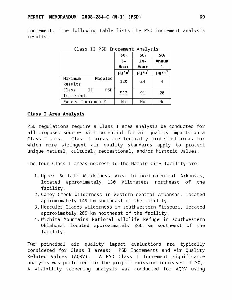
SPECIFIC CONDITIONS NO. 2008-284-C (M-1) (PSD) 8
Measurement Approach
Opacity shall be monitored using a certified Visible Emissions Evaluator
Differential pressure transducer
Scrubber liquid pump electric power consumption is measured using an ammeter
Indicator Range
An excursion is defined as an opacity greater than 20% except for one six-minute period per hour not to exceed 60% opacity
An excursion is defined as a daily pressure differential below 6.7 inches water column. Excursions trigger corrective actions and a reporting requirement on the Semi-Annual Report (SAR).
An excursion is defined as an hourly pump power usage below 122 amps on the KVS Kiln or 51 amps on the third pump split to the two kilns. Excursions trigger corrective actions, and a reporting requirement on the SAR.
Data Representativeness Performance Criteria
The Visible Emissions Evaluator shall be positioned in compliance with EPA Method 9 of 40 CFR Part 60, Appendix A
The differential pressure manometer monitors the static pressures upstream and downstream of the wet scrubber
Ammeters for each pump will measure current at each pump connection.
QA/QC Practices and Criteria
The Visible Emissions Evaluator shall be certified every six months in Method 9
Monthly comparison to U-tube manometer. Acceptability criterion is 1 inch WC.
The ammeter shall be calibrated at least annually in accordance with manufacturer specifications.
Monitoring Frequency
One six-minute average shall be conducted per month.
Measured daily Measured continuously during kiln operation
Data Collection Procedure
Data are recorded manually.
Data are recorded manually or electronically.
Recorded at least once per hour either in a log or by computer.
Averaging Period Six-minute averages Daily 1-hour
13. Compliance assurance monitoring for the Vertical Kiln shall be included in the next renewal operating permit.
14. The Fuller Kiln shall be shut down and rendered inoperable before the Vertical Kiln becomes operational. The Vertical Kiln will be considered operational only after a reasonable shakedown period, not to exceed 180 days. Until such time, the Fuller Kiln and associated equipment will continue to operate according to the requirements of Permit No. 2008-284-TVR.
15. The permittee shall notify the Air Quality Division of DEQ no later than 15 days after the
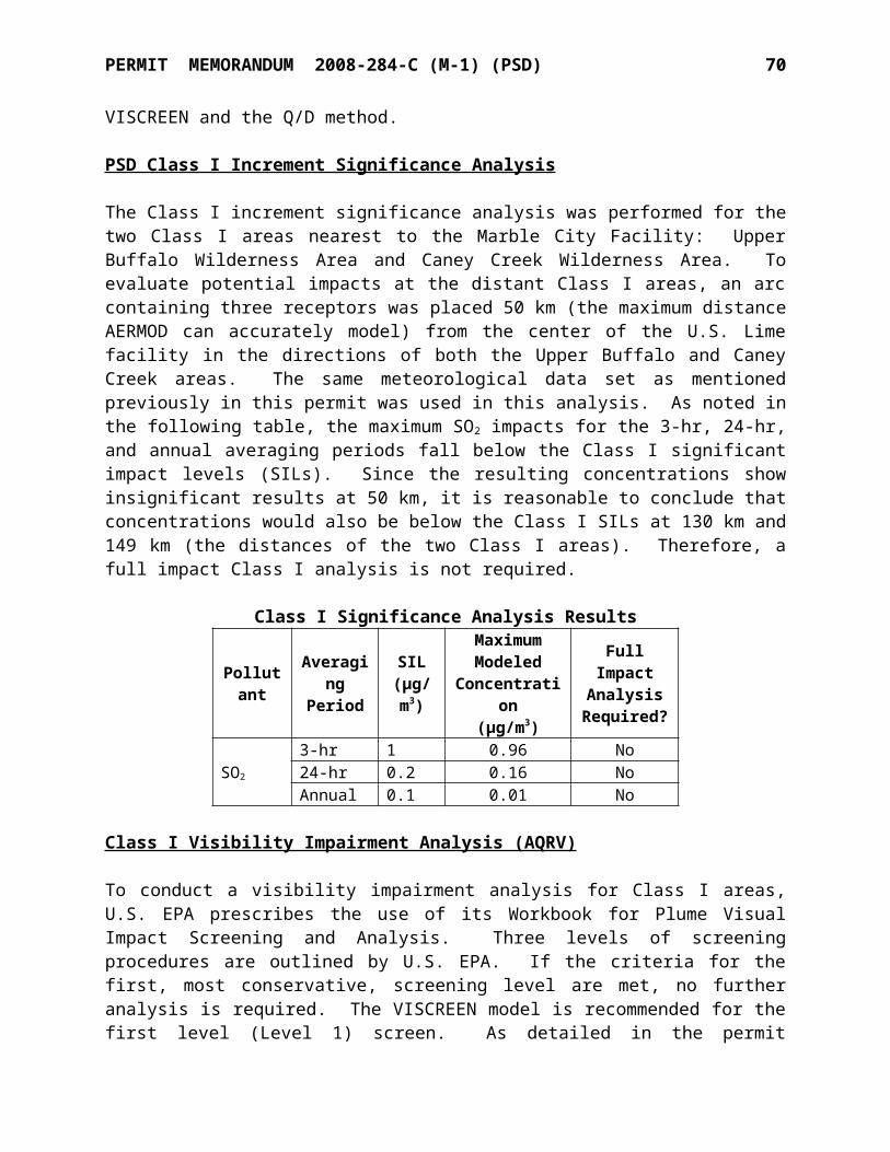
SPECIFIC CONDITIONS NO. 2008-284-C (M-1) (PSD) 9
following events occur:1) The date of initial start-up of the new Vertical Kiln (30-DC-1),2) The date that the Fuller Kiln (P-8) is rendered inoperable as described above, and3) The date the new Vertical Kiln shakedown period ends or 180 days after initial start-
up of the new kiln system, whichever is sooner.EUG-5 Kiln Department - Grandfathered
EU Point Description Opacity LimitEK-8 F-41 KVS Kiln Stone Bin 20%3-SN-1B
3-DC-1
Quicklime Screen 20%3-QS-1 Quicklime Bin #1 - KVS ROK/ Vertical Kiln 20%3-QS-2 Quicklime Bin #2 - KVS Jumbo Pebble 20%3-QS-3 Quicklime Bin #3 - KVS Jumbo Pebble 20%3-QS-4 Quicklime Bin #4 - KVS Jumbo Pebble 20%3-QS-5 Quicklime Bin #5 - KVS Sm. Pebble 20%3-QS-6 Quicklime Bin #6 - KVS Sm. Pebble 20%3-QS-7 3-DC-7 Quicklime Bin #7 - Dolomitic Lime 20%3-QS-8 Quicklime Bin #8 - KVS Sm. Pebble 20%3-CR-1 - Roll Crusher - KVS Oversize Enclosed3-SN-3 - Screen - Lime Recycle Scalping Enclosed3-MT-2 - Material Transfer (Stone) 20%
1. The opacity of discharges from the above equipment shall not exceed 20% opacity.[OAC 252:100-25]
2. Compliance with opacity limitations shall be demonstrated as follows:[OAC 252:100-8-6(a)]
a. The permittee shall conduct Method 9 or Method 22 visual observations of emissions from each point listed above at least once per week during which a unit operates. In no case shall the observation period be less than six minutes in duration. If visible emissions are observed for six minutes in duration for any observation period and such emissions are not the result of a malfunction, then the permittee shall conduct, for the identified points, within 24 hours, a visual observation of emissions, in accordance with 40 CFR Part 60, Appendix A, Method 9.
b. When four consecutive weekly visible emission observations or Method 9 observations show no visible emissions, or no emissions of a shade or density greater than twenty (20) percent equivalent opacity, respectively, the frequency may be reduced to monthly visual observations, as above. Upon any showing of non-compliance the observation frequency shall revert to weekly.
c. If a Method 9 observation exceeds 20% opacity the permittee shall conduct at least two additional Method 9 observations within the next 24-hours.
d. If more than one six-minute Method 9 observation exceeds 20% opacity in any consecutive 60 minutes; or more than three six-minute Method 9 observations in any consecutive 24 hours exceeds 20% opacity; or if any six-minute Method 9 observation exceeds 60% opacity; the owner or operator shall comply with the provisions for excess emissions during start-up, shut-down, and malfunction of air pollution control equipment.
3. At least once per operating day, the permittee shall monitor and record the
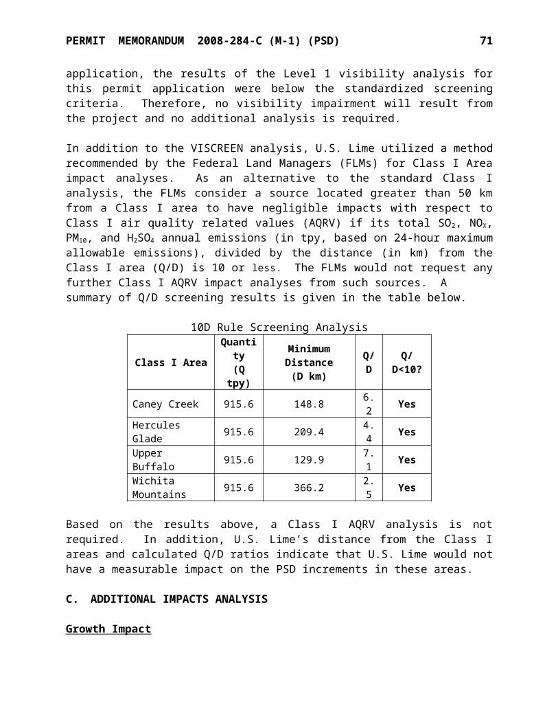
SPECIFIC CONDITIONS NO. 2008-284-C (M-1) (PSD) 10
pressure differential of the dust collectors 3-DC-1 and 3-DC-7. The dust collectors shall be operated at a pressure differential of at least 1 inch WG and no greater than 10 inch WG.
EUG-6 Insignificant Activities Emissions from the equipment listed below are estimated based on existing equipment items and are insignificant (less than 5 TPY).
EU Point Description Process Rate PM10
EmissionsTPH TPY lb/hr TPY
6-SC-3 - Hydrator clean-out screw conveyor 0.05 400 0.10 0.44
EU Point Description VolumeGal
ThroughputGal/Yr
VOCEmissions
TPYM-6 P-13 Diesel Storage Tank 12,000 175,000 0.005
1. The opacity of discharges from EU 6-SC-3 shall not exceed 20% opacity.[OAC 252:100-25]
2. Compliance with opacity limitations shall be demonstrated as follows:[OAC 252:100-8-6(a)]
a. The permittee shall conduct Method 9 or Method 22 visual observations of emissions from each point listed above at least once per week during which a unit operates. In no case shall the observation period be less than six minutes in duration. If visible emissions are observed for six minutes in duration for any observation period and such emissions are not the result of a malfunction, then the permittee shall conduct, for the identified points, within 24 hours, a visual observation of emissions, in accordance with 40 CFR Part 60, Appendix A, Method 9.
b. When four consecutive weekly visible emission observations or Method 9 observations show no visible emissions, or no emissions of a shade or density greater than twenty (20) percent equivalent opacity, respectively, the frequency may be reduced to monthly visual observations, as above. Upon any showing of non-compliance the observation frequency shall revert to weekly.
c. If a Method 9 observation exceeds 20% opacity the permittee shall conduct at least two additional Method 9 observations within the next 24-hours.
d. If more than one six-minute Method 9 observation exceeds 20% opacity in any consecutive 60 minutes; or more than three six-minute Method 9 observations in any consecutive 24 hours exceeds 20% opacity; or if any six-minute Method 9 observation exceeds 60% opacity; the owner or operator shall comply with the provisions for excess emissions during start-up, shut-down, and malfunction of air pollution control equipment.
SPECIFIC CONDITIONS NO. 2008-284-C (M-1) (PSD) 11
EUG-7Hydrator Department
EU Point Description PM10
lb/hr TPY6-QLS-1 6-DC-2 25-Ton Hydrate Feed Bin 1.13 1.656-WS-1 - Hydrator 3.84 5.626-WZ-1 Whizzer Classifier - Hydrate6-HS-1
6-DC-1
Hydrate Bin - East
0.40 0.596-HS-2 Hydrate Bin - West6-LS-2 Loading Spout - West Hydrate Bin6-LS-1 Loading Spout - East Hydrate Bin6-HB-1 Hydrate Bagger
1. The opacity of discharges from the above equipment shall not exceed 20% opacity.[OAC 252:100-25]
2. Compliance with opacity limitations shall be demonstrated as follows:[OAC 252:100-8-6(a)]
a. The permittee shall conduct Method 9 or Method 22 visual observations of emissions from each point listed above at least once per week during which a unit operates. In no case shall the observation period be less than six minutes in duration. If visible emissions are observed for six minutes in duration for any observation period and such emissions are not the result of a malfunction, then the permittee shall conduct, for the identified points, within 24 hours, a visual observation of emissions, in accordance with 40 CFR Part 60, Appendix A, Method 9.
b. When four consecutive weekly visible emission observations or Method 9 observations show no visible emissions, or no emissions of a shade or density greater than twenty (20) percent equivalent opacity, respectively, the frequency may be reduced to monthly visual observations, as above. Upon any showing of non-compliance the observation frequency shall revert to weekly.
c. If a Method 9 observation exceeds 20% opacity the permittee shall conduct at least two additional Method 9 observations within the next 24-hours.
d. If more than one six-minute Method 9 observation exceeds 20% opacity in any consecutive 60 minutes; or more than three six-minute Method 9 observations in any consecutive 24 hours exceeds 20% opacity; or if any six-minute Method 9 observation exceeds 60% opacity; the owner or operator shall comply with the provisions for excess emissions during start-up, shut-down, and malfunction of air pollution control equipment.
3. At least once per operating day, the permittee shall monitor and record the pressure differential of the dust collectors 6-DC-1 and 6-DC-2. The dust collectors shall be operated at a pressure differential of at least 1 inch WG and no greater than 10 inch WG.
SPECIFIC CONDITIONS NO. 2008-284-C (M-1) (PSD) 12
EUG-8Stock Piles
EU Point DescriptionConstruction/Modification
Date8-PILE-5 - Vertical Kiln Feed Pile 1964/20134-PILE-1 - KVS Fines Pile 19714-PILE-2 - Vertical Kiln Fines Pile 20138-PILE-3 - Small KVS Feed Pile 19648-PILE-4 - Large KVS Feed Pile 19647-PILE-1 - Fines plant stockpile 19885-PILE-1 - Coal stockpile 1976/20135-PILE-2 - Coke stockpile 2001/20138-PILE-2 - Fines Plant Stockpile / Waste Pile 19711-PILE-2 - Waste Pile 19641-PILE-1 - Waste Pile 19648-PILE-1 - Crusher screenings pile / Primary Surge Pile 19643-PILE-1 - Oversized Tramp Pile 2013
1. Stock piles shall be watered when necessary to control emissions of fugitive dust. Other dust control measures may be used provided that the measures are adequate to achieve compliance with applicable requirements. [OAC 252:100-29]
EUG-9Unpaved Haul RoadsEU Point Description Construction DateR-1 - Unpaved Quarry Haul Roads 1964
1. Haul roads shall be watered when necessary to control emissions of fugitive dust.[OAC 252:100-29]
EUG-16 Lime Storage & Handling Department
EU Point DescriptionPM10
Emissionslb/hr TPY
3-BQ-1
3-DC-3
Briquetter #1
0.90 3.953-BQ-2 Briquetter #23-BC-30 Belt Conveyor - Bin #12 & 13 To Loadout Transfer3-BC-31 Belt Conveyor - Loadout Transfer3-SN-7 /3-SN-8
3-DC-5 Vertical Kiln Scalping and 4-Deck Screens 0.78 3.38
3-QS-17 Lime Bin #17 - Vertical Kiln ROK
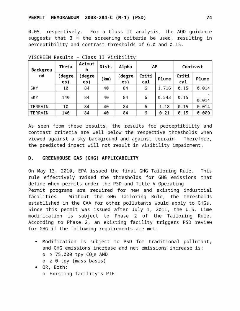
SPECIFIC CONDITIONS NO. 2008-284-C (M-1) (PSD) 13
EU Point DescriptionPM10
Emissionslb/hr TPY
3-QS-18 Lime Bin #18 - Vertical Kiln ROK3-CR-2 Roll Crusher - Vertical Kiln Lime3-LS-10 3-DC-10 Loading Spout - Lime Bin #10 0.06 0.263-BC-33
3-DC-30
Belt Conveyor - Lime Transfer to Loadout
0.12 0.513-BC-34 Belt Conveyor - Lime Transfer to Loadout3-BC-36 Belt Conveyor - Loadout3-LS-30 Loading Spout - Quicklime To Truck3-VBF-26 Vibrating Feeders (2)3-BC-32
3-DC-31
Belt Conveyor - Loadout Transfer
0.12 0.513-BC-35 Belt Conveyor - Lime Loadout3-LS-31 Loading Spout - Quicklime To Rail3-VBF-27 Vibrating Feeder 3-VBF-29 - Vibrating Feeders (5) - Enclosed 0.08 0.033-SN-6
3-DC-1
Static Grizzly
1.28 5.60
3-QS-9 Quicklime Bin #9 - Vertical Kiln Lg. Pebble3-QS-10 Quicklime Bin #10 - KVS Waste Lime3-QS-11 Quicklime Bin #11 - Vertical Kiln Lg. Pebble3-QS-14 Quicklime Bin #14 - KVS Fines3-QS-15 Quicklime Bin #15 - Vertical Kiln /KVS Fines3-QS-12 3-DC-2 Quicklime Bin #12 - Vertical Kiln Sm. Pebble 0.78 3.383-QS-16 Quicklime Bin #16 - Vertical Kiln Fines7-VBF-3
-
Vibrating Feeder 0.36 0.433-VBF-1 Vibrating Feeders (9) - Enclosed 0.18 0.02
3-MT-1 Material Transfer (Lime) 0.025 0.004
1. Compliance with emissions limitations shall be demonstrated as follows:[OAC 252:100-8-6(a)]
a. The dust collectors listed above shall be operated at a pressure differential of at least 1 inch WG and no greater than 10 inch WG when the process is operating. At least once per operating day, the permittee shall record the pressure differential.
b. The permittee shall conduct Method 9 or Method 22 visual observations of emissions from each point listed above at least once per week during which a unit operates. In no case shall the observation period be less than six minutes in duration. If visible emissions are observed for six minutes in duration for any observation period and such emissions are not the result of a malfunction, then the permittee shall conduct, for the identified points, within 24 hours, a visual observation of emissions, in accordance with 40 CFR Part 60, Appendix A, Method 9.
c. When four consecutive weekly visible emission observations or Method 9 observations show no visible emissions, or no emissions of a shade or density greater than twenty (20) percent equivalent opacity, respectively, the frequency may be reduced to monthly visual observations, as above. Upon any showing of non-compliance the observation frequency shall revert to weekly.
d. If a Method 9 observation exceeds 20% opacity the permittee shall conduct at least two additional Method 9 observations within the next 24-hours.
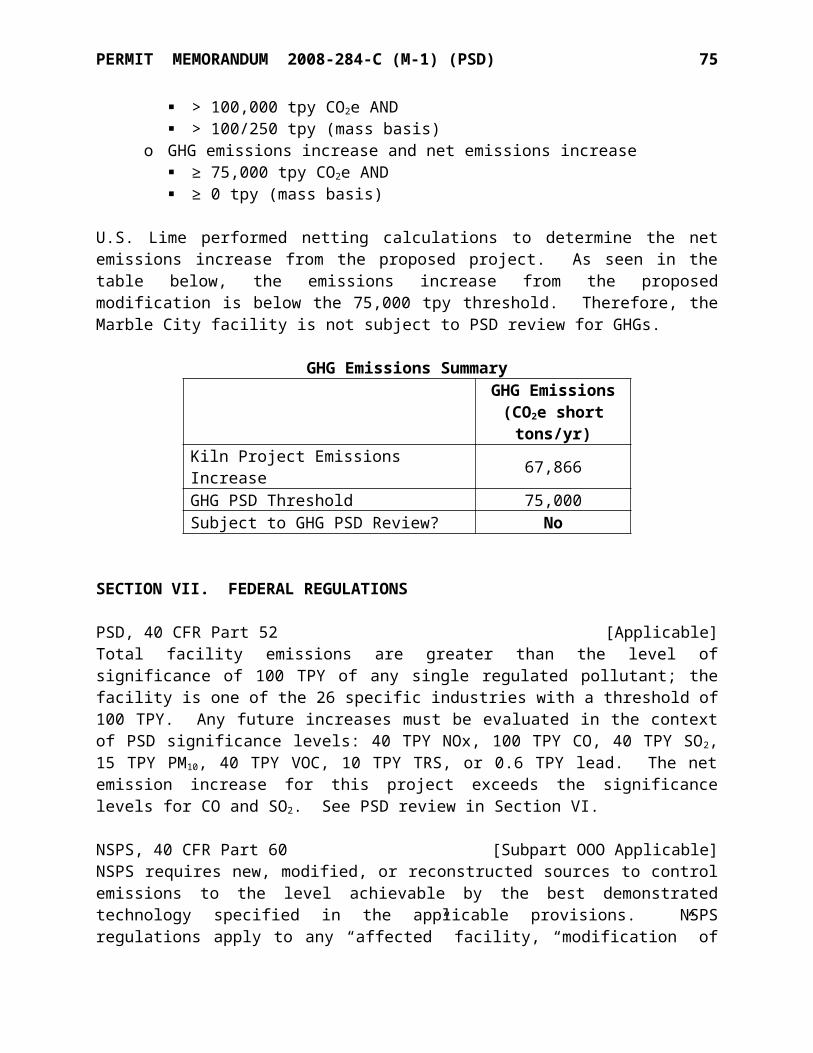
SPECIFIC CONDITIONS NO. 2008-284-C (M-1) (PSD) 14
e. If more than one six-minute Method 9 observation exceeds 20% opacity in any consecutive 60 minutes; or more than three six-minute Method 9 observations in any consecutive 24 hours exceeds 20% opacity; or if any six-minute Method 9 observation exceeds 60% opacity; the owner or operator shall comply with the provisions for excess emissions during start-up, shut-down, and malfunction of air pollution control equipment.
[OAC 252:100-25]EUG-17 Emergency Reciprocating Internal Combustion Engines (RICE)
EU Point Description Process RateHP
1-STM-1 - KVS Kiln emergency diesel drive engine 851-STM-2 - Vertical Kiln emergency generator engine 635
1. Given their emergency backup status, emissions from the equipment listed above are insignificant (less than 5 TPY). However, the engines are subject to a federal applicable requirement as presented below.
2. The emergency engines for the KVS and Vertical Kilns are subject to 40 CFR Part 63 (NESHAP) Subpart ZZZZ and shall meet all applicable provisions according to the following compliance dates:a. KVS Kiln emergency diesel drive engine: May 3, 2013.b. Vertical Kiln emergency generator engine: The permittee must comply with all
applicable provisions of 40 CFR 60 (NSPS) Subpart IIII upon startup of the engine.
EUG-18 Gasoline Storage Tank
EU Point Description
Process Rate ConstructionOr
Last ModifiedDate
TPH TPY Gal/Yr
M-7 P-14 Gasoline storage tank (2000-gal) - - 50,000 1998
1. Emissions from the equipment listed above are insignificant (less than 5 TPY). However, the gasoline tank is subject to a federal applicable requirement as presented below.
2. The gasoline storage tank is subject to the work practice standards in 40 CFR 63.11116 (NESHAP Subpart CCCCCC) and the permittee must not allow gasoline to be handled in a manner that would result in vapor releases to the atmosphere for extended periods of time, including taking measures to:a. Minimize gasoline spills;b. Clean up spills as expeditiously as practicable; andc. Cover all gasoline containers and all gasoline storage tank fill-pipes with a gasketed
seal when not in use.3. Gasoline throughput shall not exceed 10,000 gallons per month.4. The permittee is not required to submit notifications or reports as specified in §63.11125,
§63.111126, or 40 CFR 63 Subpart A, but must have records available within 24 hours of a request by the Administrator to document the gasoline throughput.
2. Facility-wide Conditions
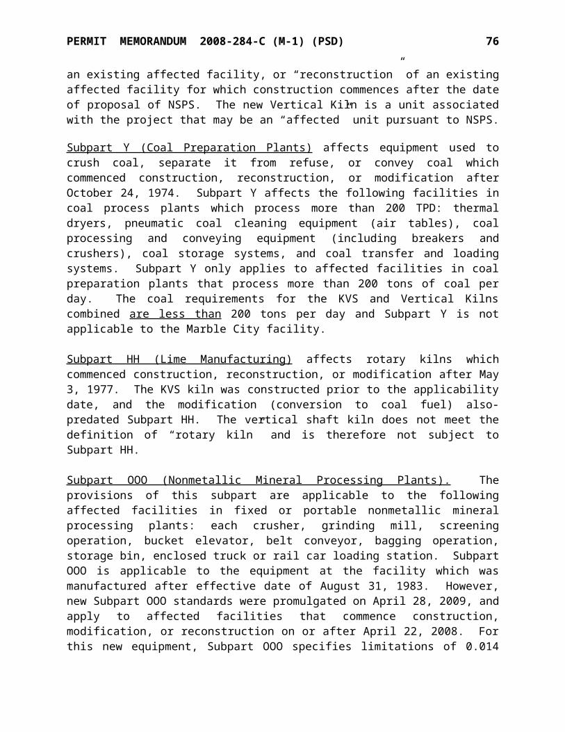
SPECIFIC CONDITIONS NO. 2008-284-C (M-1) (PSD) 15
1. The facility shall be authorized to operate continuously (24 hours per day, every day of the year). [OAC 252:100-8-6(a)]
2. The Crushing, Screening, Calcining, Hydrating, and Product Load-out operations shall be checked at least weekly for spills of dry material. If such spills are discovered, they shall be recorded on a log sheet or check list and the spilled material shall be cleaned up within 3 days of discovery.
3. The permittee shall keep records of operations as listed below. These records shall be maintained on-site and accessible to regulatory personnel upon request. Required records shall be retained for a period of at least five years following dates of recording.
[OAC 252:100-43]a. Crusher Department process rate (12-month rolling totals).b. Records as required by NSPS Subpart OOO for the Crusher Department.c. Records as required by NSPS Subpart OOO for the Fines Department.d. Records as required by NSPS Subpart OOO for the Kiln Department (Non-
Grandfathered).e. Kiln Department - Non-Grandfathered equipment process rates (TPH averaged
monthly).f. Hydrator Department process rates (TPH averaged monthly).g. Records of opacity testing for the equipment in EUGs 1, 3, 4, 5, 6, 7, and 16. h. Fines Department process rate (TPH averaged daily).i. Pressure differentials of the Vertical Kiln baghouse (daily when operated).j. Pressure differentials of the KVS Kiln wet scrubber (daily when operated).k. Scrubber liquor pump electric power usage (continuous when operated).l. EUG-3 (Fines), EUG-4 (Kiln), EUG-5 (Kiln Grandfathered), EUG-16 (Lime Storage
& Handling) and EUG-7 (Hydrator) dust collector pressure differential (daily when operated).
m. Kiln coal/coke sulfur content (daily).n. Records of inspection of the Crushing, Screening, Calcining, Hydrating, and Product
Load-out operations for spills of dry material, and clean-up of such materials when discovered (weekly).
4. Reasonable precautions shall be taken to minimize fugitive dust emissions from all activities. These precautions may include, but are not limited to: [OAC 252:100-29]a. Use of water or chemicals on roads, stockpiles, and materials during transfer
operations.b. Application of other coatings or coverings to substances susceptible to becoming air-
borne or wind-borne.c. Covering or wetting material in trucks.d. Planting and maintaining vegetation coverings or windbreaks.e. Locate stockpiles as to provide minimum exposure to high winds and avoid open
spaces in line with neighboring homes and businesses. f. Curtail operations to the extent necessary to comply with the emissions limitations.
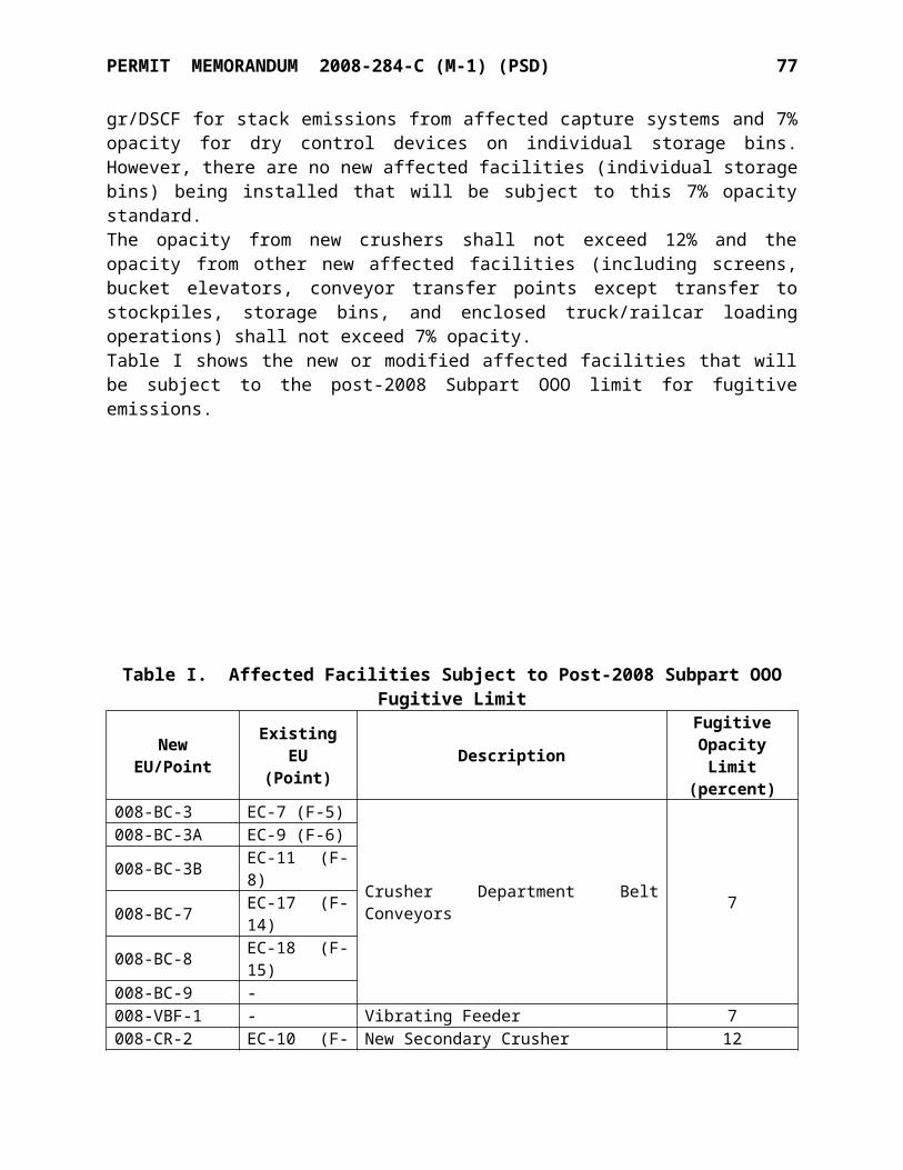
SPECIFIC CONDITIONS NO. 2008-284-C (M-1) (PSD) 16
5. The Permit Shield (Standard Conditions, Section VI) is extended to the following requirements that have been determined to be inapplicable to this facility.
[OAC 252:100-8-6(d)(2)]
a. OAC 252:100-11 Alternative Emissions Reductionb. OAC 252:100-17 Incineratorc. OAC 252:100-23 Cotton Ginsd. OAC 252:100-24 Grain Elevatorse. OAC 252:100-35 Carbon Monoxidef. OAC 252:100-39 VOC in Non-Attainment Areasg. 40 CFR Part 61 NESHAP
6. The permittee shall apply for a modification of their current Title V operating permit within 180 days of operational start-up.
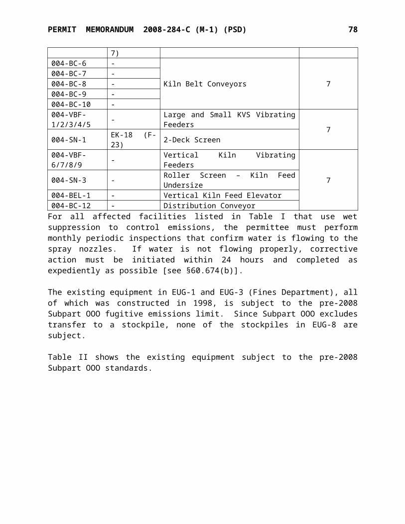
MAJOR SOURCE AIR QUALITY PERMITSTANDARD CONDITIONS
(July 21, 2009)
SECTION I. DUTY TO COMPLY
A. This is a permit to operate / construct this specific facility in accordance with the federal Clean Air Act (42 U.S.C. 7401, et al.) and under the authority of the Oklahoma Clean Air Act and the rules promulgated there under. [Oklahoma Clean Air Act, 27A O.S. § 2-5-112]
B. The issuing Authority for the permit is the Air Quality Division (AQD) of the Oklahoma Department of Environmental Quality (DEQ). The permit does not relieve the holder of the obligation to comply with other applicable federal, state, or local statutes, regulations, rules, or ordinances. [Oklahoma Clean Air Act, 27A O.S. § 2-5-112]
C. The permittee shall comply with all conditions of this permit. Any permit noncompliance shall constitute a violation of the Oklahoma Clean Air Act and shall be grounds for enforcement action, permit termination, revocation and reissuance, or modification, or for denial of a permit renewal application. All terms and conditions are enforceable by the DEQ, by the Environmental Protection Agency (EPA), and by citizens under section 304 of the Federal Clean Air Act (excluding state-only requirements). This permit is valid for operations only at the specific location listed.
[40 C.F.R. §70.6(b), OAC 252:100-8-1.3 and OAC 252:100-8-6(a)(7)(A) and (b)(1)]
D. It shall not be a defense for a permittee in an enforcement action that it would have been necessary to halt or reduce the permitted activity in order to maintain compliance with the conditions of the permit. However, nothing in this paragraph shall be construed as precluding consideration of a need to halt or reduce activity as a mitigating factor in assessing penalties for noncompliance if the health, safety, or environmental impacts of halting or reducing operations would be more serious than the impacts of continuing operations. [OAC 252:100-8-6(a)(7)(B)]
SECTION II. REPORTING OF DEVIATIONS FROM PERMIT TERMS
A. Any exceedance resulting from an emergency and/or posing an imminent and substantial danger to public health, safety, or the environment shall be reported in accordance with Section XIV (Emergencies). [OAC 252:100-8-6(a)(3)(C)(iii)(I) & (II)]
B. Deviations that result in emissions exceeding those allowed in this permit shall be reported consistent with the requirements of OAC 252:100-9, Excess Emission Reporting Requirements.
[OAC 252:100-8-6(a)(3)(C)(iv)]
C. Every written report submitted under this section shall be certified as required by Section III (Monitoring, Testing, Recordkeeping & Reporting), Paragraph F.
[OAC 252:100-8-6(a)(3)(C)(iv)]
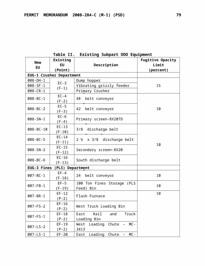
TITLE V PERMIT STANDARD CONDITIONS July 21, 2009 2
SECTION III. MONITORING, TESTING, RECORDKEEPING & REPORTING
A. The permittee shall keep records as specified in this permit. These records, including monitoring data and necessary support information, shall be retained on-site or at a nearby field office for a period of at least five years from the date of the monitoring sample, measurement, report, or application, and shall be made available for inspection by regulatory personnel upon request. Support information includes all original strip-chart recordings for continuous monitoring instrumentation, and copies of all reports required by this permit. Where appropriate, the permit may specify that records may be maintained in computerized form.
[OAC 252:100-8-6 (a)(3)(B)(ii), OAC 252:100-8-6(c)(1), and OAC 252:100-8-6(c)(2)(B)]
B. Records of required monitoring shall include:(1) the date, place and time of sampling or measurement;(2) the date or dates analyses were performed;(3) the company or entity which performed the analyses;(4) the analytical techniques or methods used;(5) the results of such analyses; and(6) the operating conditions existing at the time of sampling or measurement.
[OAC 252:100-8-6(a)(3)(B)(i)]
C. No later than 30 days after each six (6) month period, after the date of the issuance of the original Part 70 operating permit or alternative date as specifically identified in a subsequent Part 70 operating permit, the permittee shall submit to AQD a report of the results of any required monitoring. All instances of deviations from permit requirements since the previous report shall be clearly identified in the report. Submission of these periodic reports will satisfy any reporting requirement of Paragraph E below that is duplicative of the periodic reports, if so noted on the submitted report. [OAC 252:100-8-6(a)(3)(C)(i) and (ii)]
D. If any testing shows emissions in excess of limitations specified in this permit, the owner or operator shall comply with the provisions of Section II (Reporting Of Deviations From Permit Terms) of these standard conditions. [OAC 252:100-8-6(a)(3)(C)(iii)]
E. In addition to any monitoring, recordkeeping or reporting requirement specified in this permit, monitoring and reporting may be required under the provisions of OAC 252:100-43, Testing, Monitoring, and Recordkeeping, or as required by any provision of the Federal Clean Air Act or Oklahoma Clean Air Act. [OAC 252:100-43]
F. Any Annual Certification of Compliance, Semi Annual Monitoring and Deviation Report, Excess Emission Report, and Annual Emission Inventory submitted in accordance with this permit shall be certified by a responsible official. This certification shall be signed by a responsible official, and shall contain the following language: “I certify, based on information and belief formed after reasonable inquiry, the statements and information in the document are true, accurate, and complete.”
[OAC 252:100-8-5(f), OAC 252:100-8-6(a)(3)(C)(iv), OAC 252:100-8-6(c)(1), OAC 252:100-9-7(e), and OAC 252:100-5-2.1(f)]
TITLE V PERMIT STANDARD CONDITIONS July 21, 2009 3
G. Any owner or operator subject to the provisions of New Source Performance Standards (“NSPS”) under 40 CFR Part 60 or National Emission Standards for Hazardous Air Pollutants (“NESHAPs”) under 40 CFR Parts 61 and 63 shall maintain a file of all measurements and other information required by the applicable general provisions and subpart(s). These records shall be maintained in a permanent file suitable for inspection, shall be retained for a period of at least five years as required by Paragraph A of this Section, and shall include records of the occurrence and duration of any start-up, shutdown, or malfunction in the operation of an affected facility, any malfunction of the air pollution control equipment; and any periods during which a continuous monitoring system or monitoring device is inoperative.
[40 C.F.R. §§60.7 and 63.10, 40 CFR Parts 61, Subpart A, and OAC 252:100, Appendix Q]
H. The permittee of a facility that is operating subject to a schedule of compliance shall submit to the DEQ a progress report at least semi-annually. The progress reports shall contain dates for achieving the activities, milestones or compliance required in the schedule of compliance and the dates when such activities, milestones or compliance was achieved. The progress reports shall also contain an explanation of why any dates in the schedule of compliance were not or will not be met, and any preventive or corrective measures adopted. [OAC 252:100-8-6(c)(4)]
I. All testing must be conducted under the direction of qualified personnel by methods approved by the Division Director. All tests shall be made and the results calculated in accordance with standard test procedures. The use of alternative test procedures must be approved by EPA. When a portable analyzer is used to measure emissions it shall be setup, calibrated, and operated in accordance with the manufacturer’s instructions and in accordance with a protocol meeting the requirements of the “AQD Portable Analyzer Guidance” document or an equivalent method approved by Air Quality.
[OAC 252:100-8-6(a)(3)(A)(iv), and OAC 252:100-43]
J. The reporting of total particulate matter emissions as required in Part 7 of OAC 252:100-8 (Permits for Part 70 Sources), OAC 252:100-19 (Control of Emission of Particulate Matter), and OAC 252:100-5 (Emission Inventory), shall be conducted in accordance with applicable testing or calculation procedures, modified to include back-half condensables, for the concentration of particulate matter less than 10 microns in diameter (PM10). NSPS may allow reporting of only particulate matter emissions caught in the filter (obtained using Reference Method 5).
K. The permittee shall submit to the AQD a copy of all reports submitted to the EPA as required by 40 C.F.R. Part 60, 61, and 63, for all equipment constructed or operated under this permit subject to such standards. [OAC 252:100-8-6(c)(1) and OAC 252:100, Appendix Q]
SECTION IV. COMPLIANCE CERTIFICATIONS
A. No later than 30 days after each anniversary date of the issuance of the original Part 70 operating permit or alternative date as specifically identified in a subsequent Part 70 operating permit, the permittee shall submit to the AQD, with a copy to the US EPA, Region 6, a certification of compliance with the terms and conditions of this permit and of any other applicable requirements which have become effective since the issuance of this permit.
[OAC 252:100-8-6(c)(5)(A), and (D)]
TITLE V PERMIT STANDARD CONDITIONS July 21, 2009 4
B. The compliance certification shall describe the operating permit term or condition that is the basis of the certification; the current compliance status; whether compliance was continuous or intermittent; the methods used for determining compliance, currently and over the reporting period. The compliance certification shall also include such other facts as the permitting authority may require to determine the compliance status of the source.
[OAC 252:100-8-6(c)(5)(C)(i)-(v)]
C. The compliance certification shall contain a certification by a responsible official as to the results of the required monitoring. This certification shall be signed by a responsible official, and shall contain the following language: “I certify, based on information and belief formed after reasonable inquiry, the statements and information in the document are true, accurate, and complete.” [OAC 252:100-8-5(f) and OAC 252:100-8-6(c)(1)]
D. Any facility reporting noncompliance shall submit a schedule of compliance for emissions units or stationary sources that are not in compliance with all applicable requirements. This schedule shall include a schedule of remedial measures, including an enforceable sequence of actions with milestones, leading to compliance with any applicable requirements for which the emissions unit or stationary source is in noncompliance. This compliance schedule shall resemble and be at least as stringent as that contained in any judicial consent decree or administrative order to which the emissions unit or stationary source is subject. Any such schedule of compliance shall be supplemental to, and shall not sanction noncompliance with, the applicable requirements on which it is based, except that a compliance plan shall not be required for any noncompliance condition which is corrected within 24 hours of discovery.
[OAC 252:100-8-5(e)(8)(B) and OAC 252:100-8-6(c)(3)]
SECTION V. REQUIREMENTS THAT BECOME APPLICABLE DURING THE PERMIT TERM
The permittee shall comply with any additional requirements that become effective during the permit term and that are applicable to the facility. Compliance with all new requirements shall be certified in the next annual certification. [OAC 252:100-8-6(c)(6)]
SECTION VI. PERMIT SHIELD
A. Compliance with the terms and conditions of this permit (including terms and conditions established for alternate operating scenarios, emissions trading, and emissions averaging, but excluding terms and conditions for which the permit shield is expressly prohibited under OAC 252:100-8) shall be deemed compliance with the applicable requirements identified and included in this permit. [OAC 252:100-8-6(d)(1)]
B. Those requirements that are applicable are listed in the Standard Conditions and the Specific Conditions of this permit. Those requirements that the applicant requested be determined as not applicable are summarized in the Specific Conditions of this permit. [OAC 252:100-8-6(d)(2)]
SECTION VII. ANNUAL EMISSIONS INVENTORY & FEE PAYMENT
TITLE V PERMIT STANDARD CONDITIONS July 21, 2009 5
The permittee shall file with the AQD an annual emission inventory and shall pay annual fees based on emissions inventories. The methods used to calculate emissions for inventory purposes shall be based on the best available information accepted by AQD.
[OAC 252:100-5-2.1, OAC 252:100-5-2.2, and OAC 252:100-8-6(a)(8)]
SECTION VIII. TERM OF PERMIT
A. Unless specified otherwise, the term of an operating permit shall be five years from the date of issuance. [OAC 252:100-8-6(a)(2)(A)]
B. A source’s right to operate shall terminate upon the expiration of its permit unless a timely and complete renewal application has been submitted at least 180 days before the date of expiration. [OAC 252:100-8-7.1(d)(1)]
C. A duly issued construction permit or authorization to construct or modify will terminate and become null and void (unless extended as provided in OAC 252:100-8-1.4(b)) if the construction is not commenced within 18 months after the date the permit or authorization was issued, or if work is suspended for more than 18 months after it is commenced. [OAC 252:100-8-1.4(a)]
D. The recipient of a construction permit shall apply for a permit to operate (or modified operating permit) within 180 days following the first day of operation. [OAC 252:100-8-4(b)(5)]
SECTION IX. SEVERABILITY
The provisions of this permit are severable and if any provision of this permit, or the application of any provision of this permit to any circumstance, is held invalid, the application of such provision to other circumstances, and the remainder of this permit, shall not be affected thereby.
[OAC 252:100-8-6 (a)(6)]
SECTION X. PROPERTY RIGHTS
A. This permit does not convey any property rights of any sort, or any exclusive privilege.[OAC 252:100-8-6(a)(7)(D)]
B. This permit shall not be considered in any manner affecting the title of the premises upon which the equipment is located and does not release the permittee from any liability for damage to persons or property caused by or resulting from the maintenance or operation of the equipment for which the permit is issued. [OAC 252:100-8-6(c)(6)]
SECTION XI. DUTY TO PROVIDE INFORMATION
A. The permittee shall furnish to the DEQ, upon receipt of a written request and within sixty (60) days of the request unless the DEQ specifies another time period, any information that the DEQ may request to determine whether cause exists for modifying, reopening, revoking, reissuing, terminating the permit or to determine compliance with the permit. Upon request, the permittee shall also furnish to the DEQ copies of records required to be kept by the permit.
TITLE V PERMIT STANDARD CONDITIONS July 21, 2009 6
[OAC 252:100-8-6(a)(7)(E)]
B. The permittee may make a claim of confidentiality for any information or records submitted pursuant to 27A O.S. § 2-5-105(18). Confidential information shall be clearly labeled as such and shall be separable from the main body of the document such as in an attachment.
[OAC 252:100-8-6(a)(7)(E)]
C. Notification to the AQD of the sale or transfer of ownership of this facility is required and shall be made in writing within thirty (30) days after such sale or transfer.
[Oklahoma Clean Air Act, 27A O.S. § 2-5-112(G)]
SECTION XII. REOPENING, MODIFICATION & REVOCATION
A. The permit may be modified, revoked, reopened and reissued, or terminated for cause. Except as provided for minor permit modifications, the filing of a request by the permittee for a permit modification, revocation and reissuance, termination, notification of planned changes, or anticipated noncompliance does not stay any permit condition.
[OAC 252:100-8-6(a)(7)(C) and OAC 252:100-8-7.2(b)]
B. The DEQ will reopen and revise or revoke this permit prior to the expiration date in the following circumstances: [OAC 252:100-8-7.3 and OAC 252:100-8-7.4(a)(2)]
(1) Additional requirements under the Clean Air Act become applicable to a major source category three or more years prior to the expiration date of this permit. No such reopening is required if the effective date of the requirement is later than the expiration date of this permit.
(2) The DEQ or the EPA determines that this permit contains a material mistake or that the permit must be revised or revoked to assure compliance with the applicable requirements.
(3) The DEQ or the EPA determines that inaccurate information was used in establishing the emission standards, limitations, or other conditions of this permit. The DEQ may revoke and not reissue this permit if it determines that the permittee has submitted false or misleading information to the DEQ.
(4) DEQ determines that the permit should be amended under the discretionary reopening provisions of OAC 252:100-8-7.3(b).
C. The permit may be reopened for cause by EPA, pursuant to the provisions of OAC 100-8-7.3(d). [OAC 100-8-7.3(d)]
D. The permittee shall notify AQD before making changes other than those described in Section XVIII (Operational Flexibility), those qualifying for administrative permit amendments, or those defined as an Insignificant Activity (Section XVI) or Trivial Activity (Section XVII). The notification should include any changes which may alter the status of a “grandfathered source,” as defined under AQD rules. Such changes may require a permit modification.
[OAC 252:100-8-7.2(b) and OAC 252:100-5-1.1]
E. Activities that will result in air emissions that exceed the trivial/insignificant levels and that
TITLE V PERMIT STANDARD CONDITIONS July 21, 2009 7
are not specifically approved by this permit are prohibited. [OAC 252:100-8-6(c)(6)]
SECTION XIII. INSPECTION & ENTRY
A. Upon presentation of credentials and other documents as may be required by law, the permittee shall allow authorized regulatory officials to perform the following (subject to the permittee's right to seek confidential treatment pursuant to 27A O.S. Supp. 1998, § 2-5-105(18) for confidential information submitted to or obtained by the DEQ under this section):
(1) enter upon the permittee's premises during reasonable/normal working hours where a source is located or emissions-related activity is conducted, or where records must be kept under the conditions of the permit;
(2) have access to and copy, at reasonable times, any records that must be kept under the conditions of the permit;
(3) inspect, at reasonable times and using reasonable safety practices, any facilities, equipment (including monitoring and air pollution control equipment), practices, or operations regulated or required under the permit; and
(4) as authorized by the Oklahoma Clean Air Act, sample or monitor at reasonable times substances or parameters for the purpose of assuring compliance with the permit.
[OAC 252:100-8-6(c)(2)]
SECTION XIV. EMERGENCIES
A. Any exceedance resulting from an emergency shall be reported to AQD promptly but no later than 4:30 p.m. on the next working day after the permittee first becomes aware of the exceedance. This notice shall contain a description of the emergency, the probable cause of the exceedance, any steps taken to mitigate emissions, and corrective actions taken.
[OAC 252:100-8-6 (a)(3)(C)(iii)(I) and (IV)]
B. Any exceedance that poses an imminent and substantial danger to public health, safety, or the environment shall be reported to AQD as soon as is practicable; but under no circumstance shall notification be more than 24 hours after the exceedance. [OAC 252:100-8-6(a)(3)(C)(iii)(II)]
C. An "emergency" means any situation arising from sudden and reasonably unforeseeable events beyond the control of the source, including acts of God, which situation requires immediate corrective action to restore normal operation, and that causes the source to exceed a technology-based emission limitation under this permit, due to unavoidable increases in emissions attributable to the emergency. An emergency shall not include noncompliance to the extent caused by improperly designed equipment, lack of preventive maintenance, careless or improper operation, or operator error. [OAC 252:100-8-2]D. The affirmative defense of emergency shall be demonstrated through properly signed, contemporaneous operating logs or other relevant evidence that: [OAC 252:100-8-6 (e)(2)]
(1) an emergency occurred and the permittee can identify the cause or causes of the emergency;
(2) the permitted facility was at the time being properly operated;

TITLE V PERMIT STANDARD CONDITIONS July 21, 2009 8
(3) during the period of the emergency the permittee took all reasonable steps to minimize levels of emissions that exceeded the emission standards or other requirements in this permit.
E. In any enforcement proceeding, the permittee seeking to establish the occurrence of an emergency shall have the burden of proof. [OAC 252:100-8-6(e)(3)]
F. Every written report or document submitted under this section shall be certified as required by Section III (Monitoring, Testing, Recordkeeping & Reporting), Paragraph F.
[OAC 252:100-8-6(a)(3)(C)(iv)]
SECTION XV. RISK MANAGEMENT PLAN
The permittee, if subject to the provision of Section 112(r) of the Clean Air Act, shall develop and register with the appropriate agency a risk management plan by June 20, 1999, or the applicable effective date. [OAC 252:100-8-6(a)(4)]
SECTION XVI. INSIGNIFICANT ACTIVITIES
Except as otherwise prohibited or limited by this permit, the permittee is hereby authorized to operate individual emissions units that are either on the list in Appendix I to OAC Title 252, Chapter 100, or whose actual calendar year emissions do not exceed any of the limits below. Any activity to which a State or Federal applicable requirement applies is not insignificant even if it meets the criteria below or is included on the insignificant activities list.
(1) 5 tons per year of any one criteria pollutant.(2) 2 tons per year for any one hazardous air pollutant (HAP) or 5 tons per year for an
aggregate of two or more HAP's, or 20 percent of any threshold less than 10 tons per year for single HAP that the EPA may establish by rule.
[OAC 252:100-8-2 and OAC 252:100, Appendix I]
SECTION XVII. TRIVIAL ACTIVITIES
Except as otherwise prohibited or limited by this permit, the permittee is hereby authorized to operate any individual or combination of air emissions units that are considered inconsequential and are on the list in Appendix J. Any activity to which a State or Federal applicable requirement applies is not trivial even if included on the trivial activities list.
[OAC 252:100-8-2 and OAC 252:100, Appendix J]
SECTION XVIII. OPERATIONAL FLEXIBILITY
A. A facility may implement any operating scenario allowed for in its Part 70 permit without the need for any permit revision or any notification to the DEQ (unless specified otherwise in the permit). When an operating scenario is changed, the permittee shall record in a log at the facility the scenario under which it is operating. [OAC 252:100-8-6(a)(10) and (f)(1)]
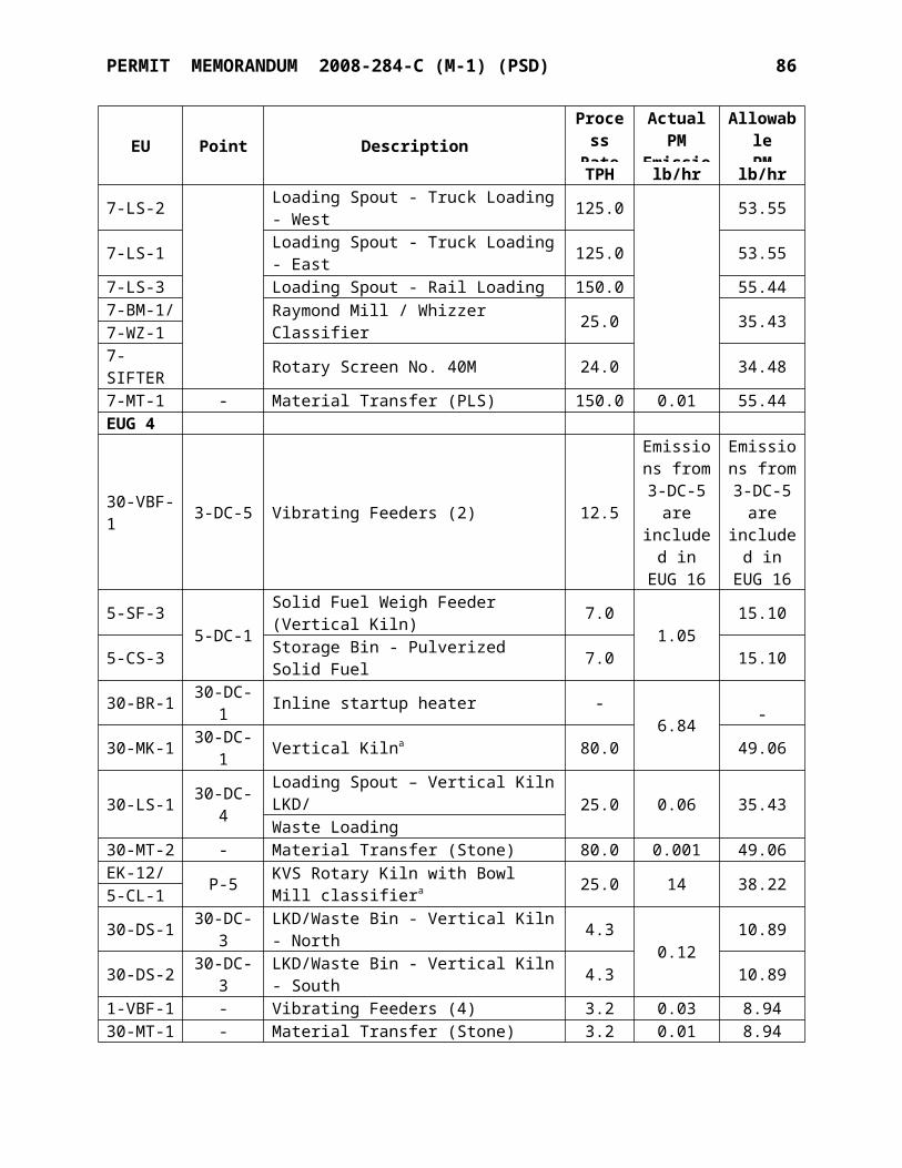
TITLE V PERMIT STANDARD CONDITIONS July 21, 2009 9
B. The permittee may make changes within the facility that:
(1)result in no net emissions increases,(2)are not modifications under any provision of Title I of the federal Clean Air Act, and(3)do not cause any hourly or annual permitted emission rate of any existing emissions unit
to be exceeded;
provided that the facility provides the EPA and the DEQ with written notification as required below in advance of the proposed changes, which shall be a minimum of seven (7) days, or twenty four (24) hours for emergencies as defined in OAC 252:100-8-6 (e). The permittee, the DEQ, and the EPA shall attach each such notice to their copy of the permit. For each such change, the written notification required above shall include a brief description of the change within the permitted facility, the date on which the change will occur, any change in emissions, and any permit term or condition that is no longer applicable as a result of the change. The permit shield provided by this permit does not apply to any change made pursuant to this paragraph. [OAC 252:100-8-6(f)(2)]
SECTION XIX. OTHER APPLICABLE & STATE-ONLY REQUIREMENTS
A. The following applicable requirements and state-only requirements apply to the facility unless elsewhere covered by a more restrictive requirement:
(1) Open burning of refuse and other combustible material is prohibited except as authorized in the specific examples and under the conditions listed in the Open Burning Subchapter.
[OAC 252:100-13](2) No particulate emissions from any fuel-burning equipment with a rated heat input of 10
MMBTUH or less shall exceed 0.6 lb/MMBTU. [OAC 252:100-19]
(3) For all emissions units not subject to an opacity limit promulgated under 40 C.F.R., Part 60, NSPS, no discharge of greater than 20% opacity is allowed except for:
[OAC 252:100-25]
(a) Short-term occurrences which consist of not more than one six-minute period in any consecutive 60 minutes, not to exceed three such periods in any consecutive 24 hours. In no case shall the average of any six-minute period exceed 60% opacity;
(b) Smoke resulting from fires covered by the exceptions outlined in OAC 252:100-13-7; (c) An emission, where the presence of uncombined water is the only reason for failure
to meet the requirements of OAC 252:100-25-3(a); or(d) Smoke generated due to a malfunction in a facility, when the source of the fuel
producing the smoke is not under the direct and immediate control of the facility and the immediate constriction of the fuel flow at the facility would produce a hazard to life and/or property.
(4) No visible fugitive dust emissions shall be discharged beyond the property line on which the emissions originate in such a manner as to damage or to interfere with the use of adjacent properties, or cause air quality standards to be exceeded, or interfere with the
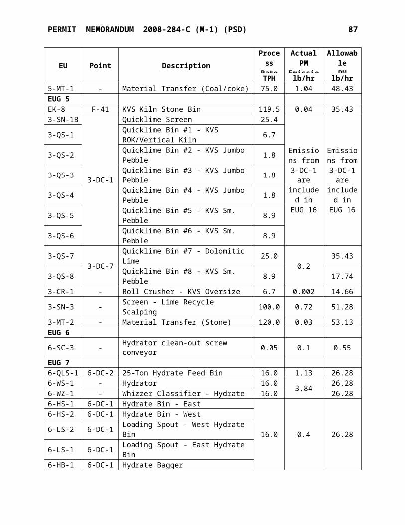
TITLE V PERMIT STANDARD CONDITIONS July 21, 2009 10
maintenance of air quality standards. [OAC 252:100-29]
(5) No sulfur oxide emissions from new gas-fired fuel-burning equipment shall exceed 0.2 lb/MMBTU. No existing source shall exceed the listed ambient air standards for sulfur dioxide. [OAC 252:100-31]
(6) Volatile Organic Compound (VOC) storage tanks built after December 28, 1974, and with a capacity of 400 gallons or more storing a liquid with a vapor pressure of 1.5 psia or greater under actual conditions shall be equipped with a permanent submerged fill pipe or with a vapor-recovery system. [OAC 252:100-37-15(b)]
(7) All fuel-burning equipment shall at all times be properly operated and maintained in a manner that will minimize emissions of VOCs. [OAC 252:100-37-36]
SECTION XX. STRATOSPHERIC OZONE PROTECTION
A. The permittee shall comply with the following standards for production and consumption of ozone-depleting substances: [40 CFR 82, Subpart A]
(1) Persons producing, importing, or placing an order for production or importation of certain class I and class II substances, HCFC-22, or HCFC-141b shall be subject to the requirements of §82.4;
(2) Producers, importers, exporters, purchasers, and persons who transform or destroy certain class I and class II substances, HCFC-22, or HCFC-141b are subject to the recordkeeping requirements at §82.13; and
(3) Class I substances (listed at Appendix A to Subpart A) include certain CFCs, Halons, HBFCs, carbon tetrachloride, trichloroethane (methyl chloroform), and bromomethane (Methyl Bromide). Class II substances (listed at Appendix B to Subpart A) include HCFCs.
B. If the permittee performs a service on motor (fleet) vehicles when this service involves an ozone-depleting substance refrigerant (or regulated substitute substance) in the motor vehicle air conditioner (MVAC), the permittee is subject to all applicable requirements. Note: The term “motor vehicle” as used in Subpart B does not include a vehicle in which final assembly of the vehicle has not been completed. The term “MVAC” as used in Subpart B does not include the air-tight sealed refrigeration system used as refrigerated cargo, or the system used on passenger buses using HCFC-22 refrigerant. [40 CFR 82, Subpart B]C. The permittee shall comply with the following standards for recycling and emissions reduction except as provided for MVACs in Subpart B: [40 CFR 82, Subpart F]
(1) Persons opening appliances for maintenance, service, repair, or disposal must comply with the required practices pursuant to § 82.156;
(2) Equipment used during the maintenance, service, repair, or disposal of appliances must comply with the standards for recycling and recovery equipment pursuant to § 82.158;
(3) Persons performing maintenance, service, repair, or disposal of appliances must be certified by an approved technician certification program pursuant to § 82.161;
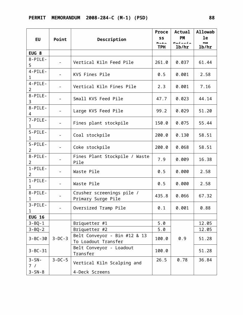
TITLE V PERMIT STANDARD CONDITIONS July 21, 2009 11
(4) Persons disposing of small appliances, MVACs, and MVAC-like appliances must comply with record-keeping requirements pursuant to § 82.166;
(5) Persons owning commercial or industrial process refrigeration equipment must comply with leak repair requirements pursuant to § 82.158; and
(6) Owners/operators of appliances normally containing 50 or more pounds of refrigerant must keep records of refrigerant purchased and added to such appliances pursuant to § 82.166.
SECTION XXI. TITLE V APPROVAL LANGUAGE
A. DEQ wishes to reduce the time and work associated with permit review and, wherever it is not inconsistent with Federal requirements, to provide for incorporation of requirements established through construction permitting into the Source’s Title V permit without causing redundant review. Requirements from construction permits may be incorporated into the Title V permit through the administrative amendment process set forth in OAC 252:100-8-7.2(a) only if the following procedures are followed:
(1) The construction permit goes out for a 30-day public notice and comment using the procedures set forth in 40 C.F.R. § 70.7(h)(1). This public notice shall include notice to the public that this permit is subject to EPA review, EPA objection, and petition to EPA, as provided by 40 C.F.R. § 70.8; that the requirements of the construction permit will be incorporated into the Title V permit through the administrative amendment process; that the public will not receive another opportunity to provide comments when the requirements are incorporated into the Title V permit; and that EPA review, EPA objection, and petitions to EPA will not be available to the public when requirements from the construction permit are incorporated into the Title V permit.
(2) A copy of the construction permit application is sent to EPA, as provided by 40 CFR § 70.8(a)(1).
(3) A copy of the draft construction permit is sent to any affected State, as provided by 40 C.F.R. § 70.8(b).
(4) A copy of the proposed construction permit is sent to EPA for a 45-day review period as provided by 40 C.F.R.§ 70.8(a) and (c).
(5) The DEQ complies with 40 C.F.R. § 70.8(c) upon the written receipt within the 45-day comment period of any EPA objection to the construction permit. The DEQ shall not issue the permit until EPA’s objections are resolved to the satisfaction of EPA.
(6) The DEQ complies with 40 C.F.R. § 70.8(d).(7) A copy of the final construction permit is sent to EPA as provided by 40 CFR § 70.8(a).(8) The DEQ shall not issue the proposed construction permit until any affected State and
EPA have had an opportunity to review the proposed permit, as provided by these permit conditions.
(9) Any requirements of the construction permit may be reopened for cause after incorporation into the Title V permit by the administrative amendment process, by DEQ as provided in OAC 252:100-8-7.3(a), (b), and (c), and by EPA as provided in 40 C.F.R. § 70.7(f) and (g).
(10) The DEQ shall not issue the administrative permit amendment if performance tests fail to demonstrate that the source is operating in substantial compliance with all permit
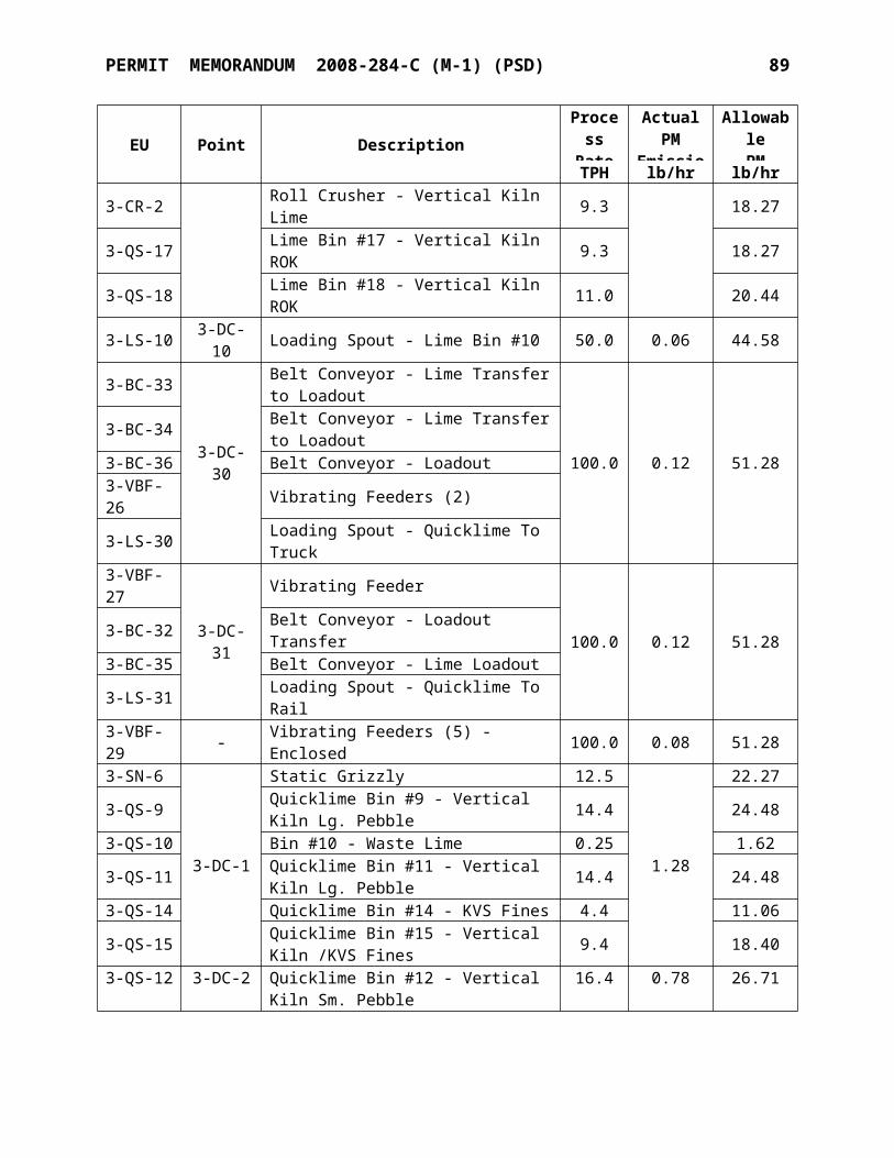
TITLE V PERMIT STANDARD CONDITIONS July 21, 2009 12
requirements.
B. To the extent that these conditions are not followed, the Title V permit must go through the Title V review process.
SECTION XXII. CREDIBLE EVIDENCE
For the purpose of submitting compliance certifications or establishing whether or not a person has violated or is in violation of any provision of the Oklahoma implementation plan, nothing shall preclude the use, including the exclusive use, of any credible evidence or information, relevant to whether a source would have been in compliance with applicable requirements if the appropriate performance or compliance test or procedure had been performed.
[OAC 252:100-43-6]
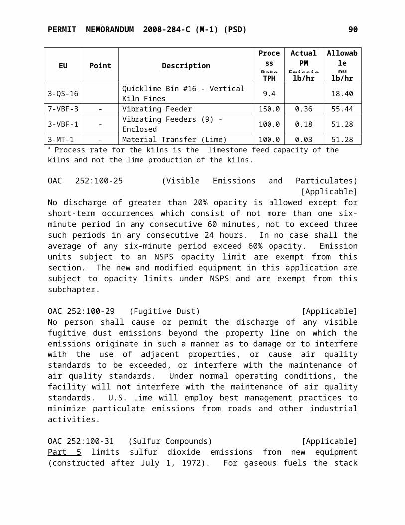
Mr. Joel B. Wilson, Plant ManagerU. S. Lime CompanyP. O. Box 160Marble City, OK 74945
SUBJECT: Permit Number: 2008-284-C (M-1) PSDLimestone Processing and Lime Calcining PlantMarble City, Sequoyah County, Oklahoma
Dear Mr. Wilson:
Enclosed is the permit authorizing construction of the referenced facility. Please note that this permit is issued subject to standard and specific conditions, which are attached. These conditions must be carefully followed since they define the limits of the permit and will be confirmed by periodic inspections.
Also note that you are required to annually submit an emissions inventory for this facility. An emissions inventory must be completed on approved AQD forms and submitted (hardcopy or electronically) by April 1st of every year. Any questions concerning the form or submittal process should be referred to the Emissions Inventory Staff at 405-702-4100.
Thank you for your cooperation. If you have any questions, please refer to the permit number above and contact me or the permit writer at (405) 702-4100.
Sincerely,
Phillip Fielder, P.E.Permits and Engineering Group ManagerAIR QUALITY DIVISION
PART 70 PERMIT
AIR QUALITY DIVISIONSTATE OF OKLAHOMA
DEPARTMENT OF ENVIRONMENTAL QUALITY707 NORTH ROBINSON, SUITE 4100
P.O. BOX 1677OKLAHOMA CITY, OKLAHOMA 73101-1677
Permit No. 2008-284-C (M-1) (PSD)
U.S. Lime & Minerals Company
having complied with the requirements of the law, is hereby granted permission to make
modifications as listed in the memorandum and specifications at the Marble City Facility at
Sec. 14 – T13N – R23E, Marble City, Sequoyah County, Oklahoma, subject to standard
conditions dated July 21, 2009 and specific conditions, both attached.
In the absence of construction commencement, this permit shall expire 18 months from the
issuance date, except as authorized under Section VIII of the Standard Conditions.
_________________________________
DEQ Form #100-890 Revised 10/20/06
Division Director Date
Air Quality Division


