OI PSF402.2 ENG - ps-automation.com · The building installation must also provide power surge...
16
Version 2017/05/30 ©2017 PS Automation GmbH Subject to changes! Operating Instructions PSF402.2
Transcript of OI PSF402.2 ENG - ps-automation.com · The building installation must also provide power surge...

Version 2017/05/30 ©2017 PS Automation GmbH
Subject to changes!
Operating Instructions PSF402.2
2
Contents Type key ............................................................................................................................................................................ 2 1. Symbols and safety ....................................................................................................................................................... 3 2. Usage as per specification ............................................................................................................................................. 4 3. Storage .......................................................................................................................................................................... 4 4. Operating conditions and installation position ............................................................................................................. 4 5. Function ........................................................................................................................................................................ 5 6. Manual operation ......................................................................................................................................................... 5 7. Valve mounting ............................................................................................................................................................. 6 7.1 Valve mounting spring extend (SE) ......................................................................................................................... 6 7.2 Valve mounting spring retract (SR) ......................................................................................................................... 6
8. Removing / closing the cover .................................................................................................................................... 7 9. Electric supply ............................................................................................................................................................... 7 9.1 Safety instructions .................................................................................................................................................. 7 9.2 Wiring diagram ........................................................................................................................................................ 8
10. Signalisation / functions .............................................................................................................................................. 8 10.1 DIP switch .............................................................................................................................................................. 8 10.2 Operating direction ............................................................................................................................................... 9 10.3 Operator push button ........................................................................................................................................... 9 10.4 Status display ...................................................................................................................................................... 10 10.5 Automatic commissioning ................................................................................................................................... 10 10.6 Manual commissioning ....................................................................................................................................... 11 10.7 Manual operation ............................................................................................................................................... 11
11. Operation .................................................................................................................................................................. 11 11.1 Split Range .......................................................................................................................................................... 12 11.2 Valve curve .......................................................................................................................................................... 12
12. Commissioning .......................................................................................................................................................... 13 13. Maintenance ............................................................................................................................................................. 13 13.1 Cleaning ............................................................................................................................................................... 13 13.2 Maintenance ....................................................................................................................................................... 13 13.3 Spare parts .......................................................................................................................................................... 13
14. Decommissioning and disposal ................................................................................................................................. 13 15. Appendix ................................................................................................................................................................... 14 15.1 Accessoires .......................................................................................................................................................... 14 15.2 Declaration of incorporation of part completed machinery and declaration of conformity in compliance with the directives on EMC and low voltage ....................................................................................... 15
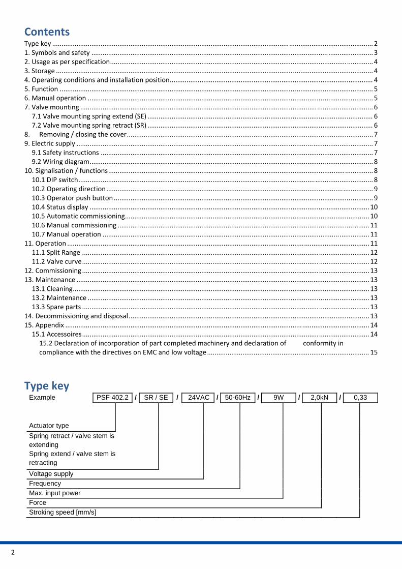
Type key Example PSF 402.2 / SR / SE / 24VAC / 50-60Hz / 9W / 2,0kN / 0,33
Actuator type
Spring retract / valve stem is extending Spring extend / valve stem is retracting
Voltage supply
Frequency
Max. input power
Force
Stroking speed [mm/s]

3
1. Symbols and safety
General dangers of non‐compliance with safety regulations PSF actuators are built at state‐of the art technology and are safe to operate. Despite of this, the actuators may be hazardous if operated by personnel that has not been sufficiently trained or minimum instructed, and if the actuators are handled improperly, or not used as per specification. This may
cause danger to life and limb of the user or a third party,
damage the actuator and other property belonging to the owner,
reduce safety and function of the actuator.
To prevent such problems, please ensure that these operating instructions and this chapter in particular have been read and understood by all personnel involved in the installation, commissioning, operation, maintenance and repair of the actuators.
Basic safety notes The actuators may only be operated by skilled and authorized operating personnel.
Make sure to follow all security advices mentioned in this manual, any national rules for accident prevention, as well as the owner´s instructions for work, operation and safety.
The isolating procedures specified in these operating instructions must be followed for all work pertaining to the installation, commissioning, operation, change of operating conditions and modes, maintenance, inspection, repair and installation of accessories.
Areas that can be under voltage have to be isolated before working on them.
Ensure that the actuators are always operated in faultless condition. Any damage or faults, and changes in the operational characteristics that may affect safety, must be reported at once.
Danger signs The following danger signs are used in this operating manual:
Caution! There is a general risk of damage related to health and/or properties.
Danger! Electrical voltages are present that may lead to death. Life threatening risks may occur due to electrical voltages!
Danger! This sign warns of hazards posing a risk to health. Ignoring these instructions can lead to injuries. Attention! Observe precautions for handling. Electrostatic sensitive devices.
Other notes The motor surface temperature may rise when maintaining, inspecting and repairing the actuator immediately
after operation. There is a danger of burning the skin!
Always consult the relevant operating instructions when mounting PS‐S accessories or operating the actuator with PS accessories.
Connections for signal in‐ and output are double isolated from circuits that can be under dangerous voltage.

4
2. Usage as per specification PSF actuators are exclusively designed to be used as electric valve actuators. They are meant to be mounted on
valves in order to run their motors.
Any other use is considered to be non‐compliant and the manufacturer cannot be held liable for any damage resulting from it.
The actuators can only be used within the limits laid out in the data sheets, catalogues and other documents. Otherwise, the manufacturer cannot be held liable for any resulting damage.
Usage as per specification includes the observance of the operating, service and maintenance conditions laid down by the manufacturer.
Not to be regarded as usage as per specification are mounting and adjusting the actuator as well as servicing. Special precautions have to be taken while doing this!
The actuators may only be used, serviced and repaired by personnel that is familiar with them and informed about potential hazards. The specific regulations for the prevention of accidents have to be observed.
Damages caused by unauthorized modifications carried out on the actuators are excluded from the manufacturer's liability.
Supply voltage may only be switched on after the proper closure of the main cover or terminal box.
3. Storage For appropriate storage, the following instructions have to be met:
Only store the actuators in ventilated, dry rooms.
Store the actuators on shelves, wooden boards, etc., to protect them from soil moisture.
Cover the actuators with plastic foil to protect them from dust and dirt.
Protect the actuators against mechanical damage.
4. Operating conditions and installation position Standard actuators may be operated at ambient temperatures according to the technical data sheet.
Operating modes correspond to IEC 60034‐1, 8: S2 for short cycle and S4 for modulating operation.
For protection against moisture and dust, the enclosure rating is IP65 according to EN 60529.
When installing the actuators, leave enough space to allow cover removal (Fig.1).
The actuator can be installed vertically or horizontally or any position in between. The actuator must not be installed with the cover pointing downwards (Fig.2).
Figure 1: Installation dimensions

5
Installation position
Outdoor usage:
When using the actuators in environments with high temperature fluctuations or high humidity, we recommend using a heating resistor.
Figure 2: Installation positions
5. Function The PSF actuators are designed as electric valve actuators with failsafe function. The actuator is mounted onto the valve via pillars. Depending on the type of valve used, mounting pillars or a special valve mounting bracket is required. Based on a brushless DC motor (BLDC) the generated torque is transmitted via a multi‐stage spur gear onto a spindle nut. The spindle nut transmits the input torque into an axial thrust force via a spindle. The linear stroke is transmitted to the valve spindle by a coupling piece. The stroke is measured and controlled by a linear 12 Bit Hall sensor. In case of mains power loss, the stroke movement is in OPEN or CLOSE direction by spring force. Electrical wiring is done to a terminal block under the actuator cover.
6. Manual operation Figure 3: Manual operation
Two push buttons are installed to drive the actuator in case of installation work such as mounting onto a valve, or setting the limit switches positions (see 10.7).
push
button
6
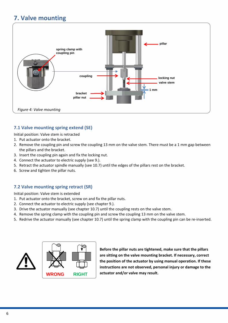
7. Valve mounting
7.1 Valve mounting spring extend (SE)
Initial position: Valve stem is retracted 1. Put actuator onto the bracket. 2. Remove the coupling pin and screw the coupling 13 mm on the valve stem. There must be a 1 mm gap between
the pillars and the bracket. 3. Insert the coupling pin again and fix the locking nut. 4. Connect the actuator to electric supply (see 9.). 5. Retract the actuator spindle manually (see 10.7) until the edges of the pillars rest on the bracket. 6. Screw and tighten the pillar nuts.
7.2 Valve mounting spring retract (SR)
Initial position: Valve stem is extended 1. Put actuator onto the bracket, screw on and fix the pillar nuts. 2. Connect the actuator to electric supply (see chapter 9.). 3. Drive the actuator manually (see chapter 10.7) until the coupling rests on the valve stem. 4. Remove the spring clamp with the coupling pin and screw the coupling 13 mm on the valve stem. 5. Redrive the actuator manually (see chapter 10.7) until the spring clamp with the coupling pin can be re‐inserted.
RIGHT WRONG
Before the pillar nuts are tightened, make sure that the pillars
are sitting on the valve mounting bracket. If necessary, correct
the position of the actuator by using manual operation. If these
instructions are not observed, personal injury or damage to the
actuator and/or valve may result.
Figure 4: Valve mounting
pillar
valve stem
locking nut coupling
pillar nut bracket
spring clamp with coupling pin
1 mm
7
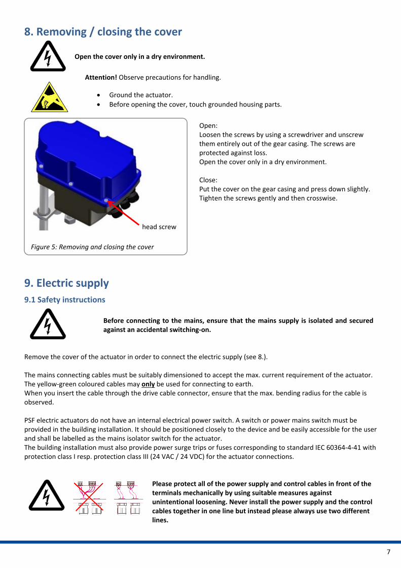
8. Removing / closing the cover
Open the cover only in a dry environment.
Figure 5: Removing and closing the cover
9. Electric supply
9.1 Safety instructions
Before connecting to the mains, ensure that the mains supply is isolated and secured against an accidental switching‐on.
Remove the cover of the actuator in order to connect the electric supply (see 8.). The mains connecting cables must be suitably dimensioned to accept the max. current requirement of the actuator. The yellow‐green coloured cables may only be used for connecting to earth. When you insert the cable through the drive cable connector, ensure that the max. bending radius for the cable is observed. PSF electric actuators do not have an internal electrical power switch. A switch or power mains switch must be provided in the building installation. It should be positioned closely to the device and be easily accessible for the user and shall be labelled as the mains isolator switch for the actuator. The building installation must also provide power surge trips or fuses corresponding to standard IEC 60364‐4‐41 with protection class I resp. protection class III (24 VAC / 24 VDC) for the actuator connections.
Please protect all of the power supply and control cables in front of the terminals mechanically by using suitable measures against unintentional loosening. Never install the power supply and the control cables together in one line but instead please always use two different lines.
head screw
Open: Loosen the screws by using a screwdriver and unscrew them entirely out of the gear casing. The screws are protected against loss. Open the cover only in a dry environment. Close: Put the cover on the gear casing and press down slightly. Tighten the screws gently and then crosswise.
Attention! Observe precautions for handling.
Ground the actuator.
Before opening the cover, touch grounded housing parts.
8
9.2 Wiring diagram
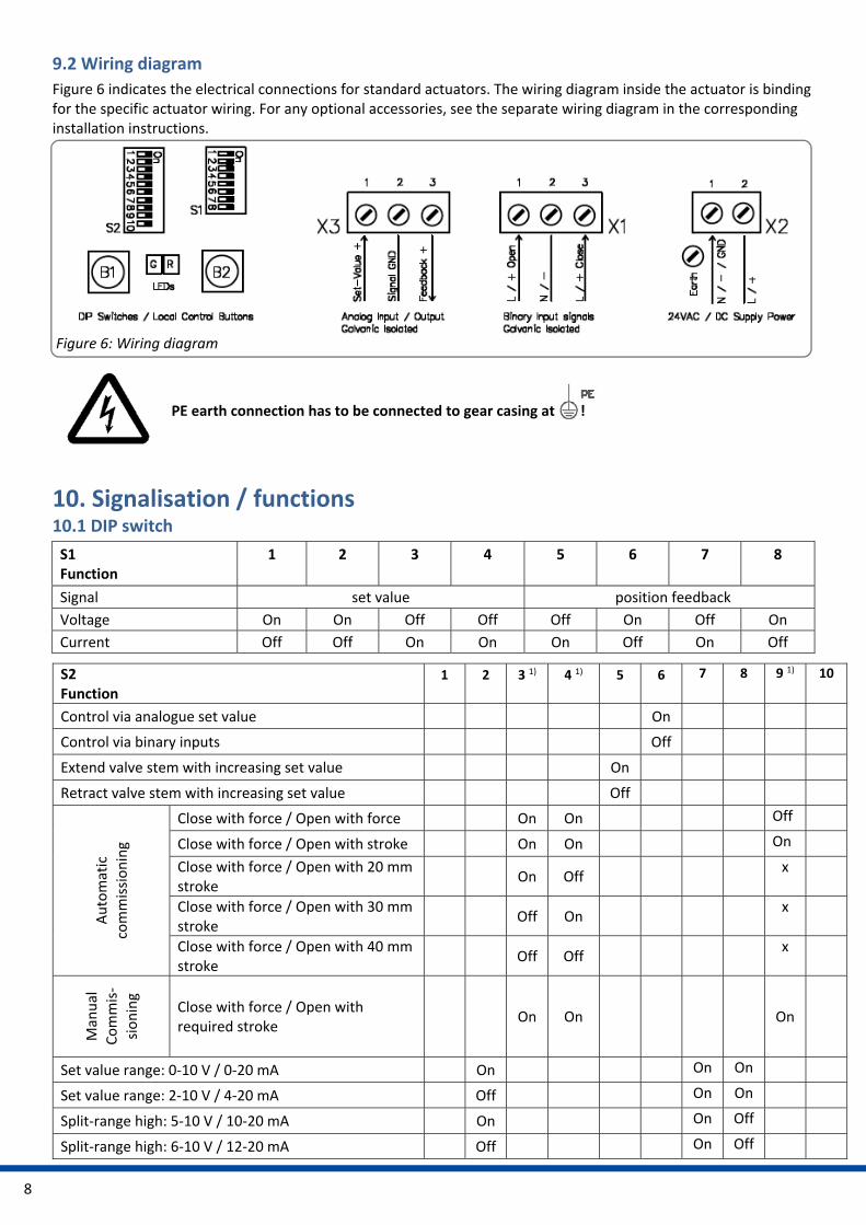
Figure 6 indicates the electrical connections for standard actuators. The wiring diagram inside the actuator is binding for the specific actuator wiring. For any optional accessories, see the separate wiring diagram in the corresponding installation instructions. Figure 6: Wiring diagram
PE earth connection has to be connected to gear casing at !
10. Signalisation / functions 10.1 DIP switch
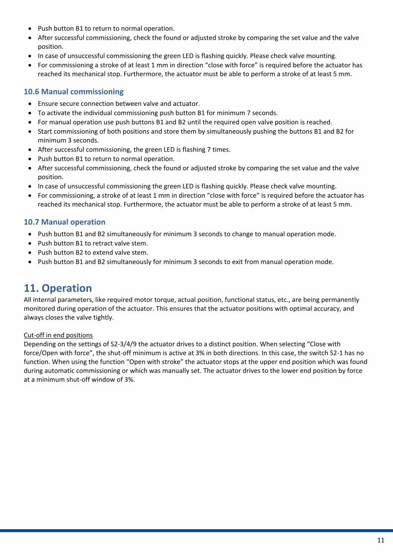
S1 Function
1
2
3
4
5
6
7
8
Signal set value position feedback
Voltage On On Off Off Off On Off On
Current Off Off On On On Off On Off
S2 Function
1
2
3 1)
4 1)
5
6
7 8 9 1) 10
Control via analogue set value On
Control via binary inputs Off
Extend valve stem with increasing set value On
Retract valve stem with increasing set value Off
Automatic
commissioning
Close with force / Open with force On On Off
Close with force / Open with stroke On On On
Close with force / Open with 20 mm stroke
On Off x
Close with force / Open with 30 mm stroke
Off On x
Close with force / Open with 40 mm stroke
Off Off x
Manual
Commis‐
sioning
Close with force / Open with required stroke
On On
On
Set value range: 0‐10 V / 0‐20 mA On On On
Set value range: 2‐10 V / 4‐20 mA Off On On
Split‐range high: 5‐10 V / 10‐20 mA On On Off
Split‐range high: 6‐10 V / 12‐20 mA Off On Off

9
1) After changing the switches S2‐3, S2‐4 and S2‐9 perform re‐calibration to activate the new operating mode.
10.2 Operating direction
10.3 Operator push button
S2 Function 1 2 3 1) 4 1) 5 6 7 8 9 1) 10
Split‐range low: 0‐5 V / 0‐10 mA On Off On
Split‐range low: 2‐6 V / 4‐12 mA Off Off On
Cut‐off by force if valve stem is in extended position On
Cut‐off by force if valve stem is in retracted position Off
Valve curve LINEAR setvalue/position Off
Valve curve QUICK OPENING setvalue/position On
Function Action push button B1 push button B2 LED sequence
Manual operation
Activate > Push 3 seconds > Push 3 seconds
Both LEDs are flashing alternately
Retract valve stem Push Green LED is flashing
Extend valve stem Push Red LED is flashing
Stop Both LEDs are flashing alternately
Exit Push 3 seconds Push 3 seconds Red or green LED is on
Figure 7: Operating direction
SE = Spring Extend: Extend actuator stem / retract valve stem
SR = Spring Retract: Retract actuator stem / extend valve stem

10
10.4 Status display
Green LED Red LED
Actuator not commissioned Off is flashing quickly
Normal operation / actuator running On Off
Normal operation / actuator stationary Off On
Manual mode active is flashing alternately is flashing alternately
Manual mode: Extend valve stem Off is flashing
Manual mode: Retract valve stem is flashing Off
Automatic commissioning running On On
Automatic and manual commissioning successful
is flashing 7 x – 1.5 seconds off On
Automatic commissioning failed is flashing quickly On
Overvoltage is flashing 1 x – 1.5 seconds off On
Undervoltage is flashing 2 x – 1.5 seconds off On
Memory error is flashing 3 x – 1.5 seconds off On
Set value error (< 1 V, < 2 mA) is flashing 4 x – 1.5 seconds off On
Torque error is flashing 5 x – 1.5 seconds off On
Under‐ / Overtemperature is flashing 6 x – 1.5 seconds off On
10.5 Automatic commissioning
Ensure secure connection between valve and actuator.
To start the automatic commissioning push button B2 minimum 7 seconds. ‐ Option 1: If adjusted “open with force – close with force”, the actuator will drive to the final open valve
position via force, and back to the final closed valve position. ‐ Option 2: If adjusted “open with calibrated stroke” (20/30/40 mm), the actuator will store the lower position
and the stroke is calculated according to the settings. If the possible travel is smaller than the preset stroke, the operating stroke will be automatically reduced to the max. possible resulting value.
After successful commissioning, the green LED is flashing 7 times.
Function Action push button B1 Push button B2 LED sequence
Automatic commissioning
Start Push 7 seconds Both LEDs are on
Commissioning finished
Green LED is flashing 7x (if commissioning is finished), green LED is flashing quickly (if commissioning failed)
Exit Push 1 x Red or green LED is on
Manual commissioning
Activate Push 7 seconds Both LEDs are flashing alternately
Rectract valve stem Push Green LED is flashing
Extend valve stem Push Red LED is flashing
Start Push 3 seconds Push 3 seconds Both LEDs are on
Exit Push 1 x Red or green LED is on
11
Push button B1 to return to normal operation.
After successful commissioning, check the found or adjusted stroke by comparing the set value and the valve position.
In case of unsuccessful commissioning the green LED is flashing quickly. Please check valve mounting.
For commissioning a stroke of at least 1 mm in direction “close with force” is required before the actuator has reached its mechanical stop. Furthermore, the actuator must be able to perform a stroke of at least 5 mm.
10.6 Manual commissioning
Ensure secure connection between valve and actuator.
To activate the individual commissioning push button B1 for minimum 7 seconds.
For manual operation use push buttons B1 and B2 until the required open valve position is reached.
Start commissioning of both positions and store them by simultaneously pushing the buttons B1 and B2 for minimum 3 seconds.
After successful commissioning, the green LED is flashing 7 times.
Push button B1 to return to normal operation.
After successful commissioning, check the found or adjusted stroke by comparing the set value and the valve position.
In case of unsuccessful commissioning the green LED is flashing quickly. Please check valve mounting.
For commissioning, a stroke of at least 1 mm in direction “close with force” is required before the actuator has reached its mechanical stop. Furthermore, the actuator must be able to perform a stroke of at least 5 mm.
10.7 Manual operation
Push button B1 and B2 simultaneously for minimum 3 seconds to change to manual operation mode.
Push button B1 to retract valve stem.
Push button B2 to extend valve stem.
Push button B1 and B2 simultaneously for minimum 3 seconds to exit from manual operation mode.
11. Operation All internal parameters, like required motor torque, actual position, functional status, etc., are being permanently monitored during operation of the actuator. This ensures that the actuator positions with optimal accuracy, and always closes the valve tightly. Cut‐off in end positions Depending on the settings of S2‐3/4/9 the actuator drives to a distinct position. When selecting “Close with force/Open with force”, the shut‐off minimum is active at 3% in both directions. In this case, the switch S2‐1 has no function. When using the function “Open with stroke” the actuator stops at the upper end position which was found during automatic commissioning or which was manually set. The actuator drives to the lower end position by force at a minimum shut‐off window of 3%.
12
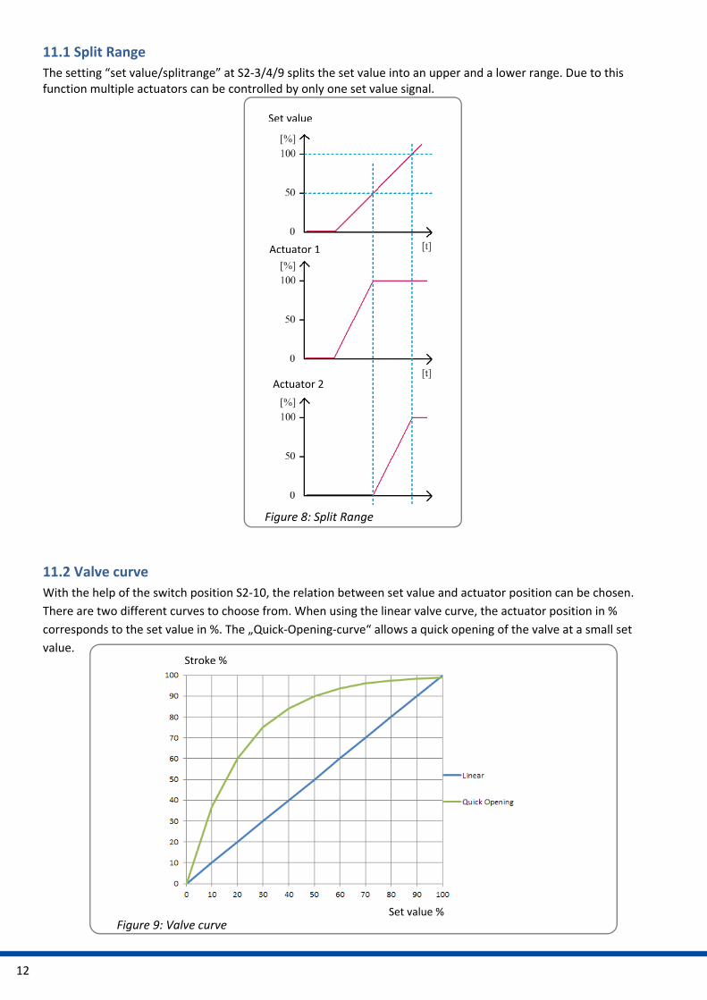
11.1 Split Range
The setting “set value/splitrange” at S2‐3/4/9 splits the set value into an upper and a lower range. Due to this function multiple actuators can be controlled by only one set value signal.
11.2 Valve curve
With the help of the switch position S2‐10, the relation between set value and actuator position can be chosen.
There are two different curves to choose from. When using the linear valve curve, the actuator position in %
corresponds to the set value in %. The „Quick‐Opening‐curve“ allows a quick opening of the valve at a small set
value.
Set value
Actuator 1
Actuator 2
Figure 8: Split Range
Figure 9: Valve curve
Stroke %
Set value %

13
12. Commissioning
Open the cover (see chapter 8.), put the actuator on the valve (see chapter 7.), connect the electric supply (see chapter 9.).
Perform automatic (see chapter 10.5) or manual (see chapter 10.6).
Close the cover.
13. Maintenance The actuators are maintenance‐free if used under the operating conditions as designated in the data sheet. The gearboxes are lubricated for life and do not require further lubrication.
Caution !
During maintenance and repair the actuator must not be operated
electrically.
13.1 Cleaning
The actuators should be cleaned dryly. Do not use abrasive cleaning agents or cleaning products containing solvents as the labelling of the safety stickers and the type plate might become illegible. Do not operate the actuator during the cleaning process.
13.2 Maintenance
The actuators have a pre‐tensioned spring inside, the gearbox housing must not be opened. Defective actuators should be returned to our plant in Bad Duerkheim, Germany, or to our representatives, to be checked for damages and their possible causes.
13.3 Spare parts
Damaged actuators should be returned to our plant in Bad Dürkheim, Germany, or to our representatives, to be checked for damages and their possible causes.
14. Decommissioning and disposal Disconnect the mains supply and ensure that it is secured against an accidental switching‐on.
Open the cover.
Remove external electrical connections.
Take off the actuator from the valve.
Disposal For its disposal, the product should be treated as waste containing electrical and electronic equipment and should not be disposed of as household waste.
The actuators have a pre‐tensioned spring inside. For disassembly please contact our plant in Bad Dürkheim.

14
15. Appendix
15.1 Accessoires
Various options are available in order to adapt the actuators to the various service conditions. For technical data, please refer to the respective data sheets.
Accessories/options
Position signal switches, mechanical
2WE 2 potential‐free position switches, mechanical, with silver‐plated changeover contacts 24 V to 230 V AC/DC @ 0.1 A – 5 A
Position signal switches gold, mechanical
2WE gold
2 potential‐free position switches, mechanical, with gold‐plated changeover contacts 5 V to 30 V AC/DC @ 1 mA – 100 mA; contact resistance 30 mOhm
Position signal relays
2 position signal relays with changeover contacts, calibrated automatically to valve stroke 24 V to 230 V AC/DC @ 0.1 A – 1 A Switching point adjustable 0‐100 % of the stroke using potentiometers
Heating resistor HR Heating resistor to prevent condensation
Wide range power supply For 100 ‐ 240 VAC 1~ supply voltage
Increased enclosure IP Increase of enclosure to IP67

15
15.2 Declaration of incorporation of part completed machinery and declaration of conformity in compliance with the directives on EMC and low voltage

16
Hong Kong MaxAuto Company Ltd. Room 2008, 20/F., CCT Telecom Building 11 Wo Shing Street Fotan, Shatin, Hong Kong Tel.: <+852> 26 87‐50 00 Fax: <+852> 81 01‐37 43 eMail: [email protected] www.maxonicauto.com China Shenzhen Maxonic Automation Control Co., Ltd. Maxonic Automation Control Mansion No. 3 Lang Shan Road, Hi‐Tech Industrial Park, Shenzhen, Guangdong, PRC. 518057 Tel.: <+86> 755 86 25 03 88 Fax: <+86> 755 86 25 03 74 eMail: [email protected] www.maxonicauto.com India PS Automation India Pvt Ltd. Srv. No. 25/1, Narhe Industrial Area, A.P. Narhegaon, Tal. Haveli, Dist. IND‐411041 Pune Tel. : <+ 91> 20 25 47 39 66 Fax : <+ 91> 20 25 47 39 66 eMail : sales@ps‐automation.in www.ps‐automation.in
Great Britain IMTEX Controls Ltd. Unit 5A, Valley Industries, Hadlow Road GB‐Tonbridge, Kent TN11 0AH Tel.: <+44> (0) 17 32‐85 03 60 Fax: <+44> (0) 17 32‐85 21 33 eMail: sales@imtex‐controls.com www.imtex‐controls.com Italy PS Automazione S.r.l. Via Pennella, 94 I‐38057 Pergine Valsugana (TN) Tel.: <+39> 04 61‐53 43 67 Fax: <+39> 04 61‐50 48 62 eMail: info@ps‐automazione.it Spain Sertemo, S.L. Pol. Ind. Alba ‐ Avda. Generalitat 15 Apartado de Correos, 142 E‐43480 Vila‐Seca (Tarragona) Tel. : <+34> 9 77 39 11 09 Fax : <+34> 9 77 39 44 80 eMail : [email protected] www.sertemo.com
PS Automation GmbH
Gesellschaft für Antriebstechnik
Philipp‐Krämer‐Ring 13
D‐67098 Bad Dürkheim
Tel.: +49 (0) 63 22 ‐ 60 03 – 0
Fax: +49 (0) 63 22 ‐ 60 03 – 20
eMail: info@ps‐automation.com
www.ps‐automation.com


![j n Õ ( Ð 2 2 è! I ' #Ó Ñ¡2 !] f ! ] f ! ! ¡ ! Õ 20_(6790)_09092014.pdf · This IS 732 ± Part1 is based on IEC 60364 series namely IEC 6036 4 ± 1, 60364-4, 60364-5 & 60364-6.](https://static.fdocuments.in/doc/165x107/5a73db587f8b9aea3e8b83b0/j-n-a-a-2-2-a-i-a-aa2-f-f-a-a-206790.jpg)