· Ohio Department of Transportation Office of Traffic Engineering January 16, 2004 To Holders of...
345
Ohio Department of Transportation Office of Traffic Engineering January 16, 2004 To Holders of the Traffic Engineering Manual (TEM): As of January 16, 2004, Parts 2, 3, 6, 11, 12 and 13 of the Traffic Engineering Manual (TEM) have been revised. Both the revised manual and a revision package are available from the ODOT Design Reference Resource Center (http://www.dot.state.oh.us/drrc/), using the “TEM” link, or from the Traffic Home Page (http://www.dot.state.oh.us/traffic/), using the Publications/Documents link. The revised pages should be printed as a double-sided document and then inserted into the manual, replacing the existing sheets. This revision involves so many pages in Parts 2, 6 and 12 that these chapters have been included in total in the “revision package.” The changes made in Parts 2, 6, 12 and 13 in this TEM revision primarily relate to updating OMUTCD related information to address changes in the recently published OMUTCD 2003 Edition. Per ODOT policy, paper copies of the revisions to this manual are no longer distributed to all holders of the manual. Revisions will only be available through the purchase of a new manual or via the web pages noted above. The TEM Publication Record on page vi of the manual lists the sections involved in this revision. A list with details of the changes made is also available. It can be accessed via the link below. Pages of the manual where text has been revised are noted by the notation “Revised January 16, 2004" at the bottom of the page. Also, a “change bar” in the right margin highlights where the revision was made. Pages that have been reprinted as part of this revision only because of changes in page numbers are noted with “(January 16, 2004)” at the bottom. When revisions in a chapter resulted in changes in a Table of Content, the full Table of Content has been reprinted as part of the revision. For questions, comments, or concerns please contact either: Juanita Elliott, P.E., Traffic Standards Engineer or Lisa McConnell, Traffic Standards Technician 614-644-8143 or [email protected] 614-728-9361 or [email protected]
Transcript of · Ohio Department of Transportation Office of Traffic Engineering January 16, 2004 To Holders of...

Ohio Department of Transportation
Office of Traffic Engineering
January 16, 2004
To Holders of the Traffic Engineering Manual (TEM):
As of January 16, 2004, Parts 2, 3, 6, 11, 12 and 13 of the Traffic Engineering Manual (TEM) have beenrevised. Both the revised manual and a revision package are available from the ODOT Design ReferenceResource Center (http://www.dot.state.oh.us/drrc/), using the “TEM” link, or from the Traffic Home Page(http://www.dot.state.oh.us/traffic/), using the Publications/Documents link. The revised pages should be printedas a double-sided document and then inserted into the manual, replacing the existing sheets. This revisioninvolves so many pages in Parts 2, 6 and 12 that these chapters have been included in total in the “revisionpackage.”
The changes made in Parts 2, 6, 12 and 13 in this TEM revision primarily relate to updating OMUTCD relatedinformation to address changes in the recently published OMUTCD 2003 Edition.
Per ODOT policy, paper copies of the revisions to this manual are no longer distributed to all holders of themanual. Revisions will only be available through the purchase of a new manual or via the web pages notedabove.
The TEM Publication Record on page vi of the manual lists the sections involved in this revision. A list withdetails of the changes made is also available. It can be accessed via the link below.
Pages of the manual where text has been revised are noted by the notation “Revised January 16, 2004" at thebottom of the page. Also, a “change bar” in the right margin highlights where the revision was made.
Pages that have been reprinted as part of this revision only because of changes in page numbers are notedwith “(January 16, 2004)” at the bottom. When revisions in a chapter resulted in changes in a Table of Content,the full Table of Content has been reprinted as part of the revision.
For questions, comments, or concerns please contact either:
Juanita Elliott, P.E., Traffic Standards Engineer or Lisa McConnell, Traffic Standards Technician614-644-8143 or [email protected] 614-728-9361 or [email protected]

Traffic EngineeringManual
October 23, 2002 Editionincludes revisions through January 16, 2004
Ohio Department of TransportationOffice of Traffic Engineering

Traffic Engineering Manual
iiOctober 23, 2002
Ohio Department of Transportation
Office of Traffic Engineering
1980 W. Broad St., P.O. Box 899
Columbus, OH 43216-0899
Web addresses:ODOT: http://www.dot.state.oh.us
Office of Traffic Engineering: http://www.dot.state.oh.us/traffic/ODOT Publications (Design Reference Resource Center): http://www.dot.state.oh.us/drrc/
The price of this Manual is $50.00. To purchase a copy, contact the ODOT Office of Contracts
at the above address, or by phone at 1-800-459-3778.
An Equal Opportunity Employer

200 SIGNS Traffic Engineering Manual
October 23, 2002 (January 16, 2004) 2-1
TABLE OF CONTENTSPart 2 - SIGNS
200 GENERAL . . . . . . . . . . . . . . . . . . . . . . . . . . . . . . . . . . . . . . . . . . . . . . . 2-9200-1 Introduction . . . . . . . . . . . . . . . . . . . . . . . . . . . . . . . . . . . . . . . . . . . . . . . . . . . 2-9200-2 Construction Projects . . . . . . . . . . . . . . . . . . . . . . . . . . . . . . . . . . . . . . . . . . . 2-9200-3 Force Account (ODOT Operations) Work . . . . . . . . . . . . . . . . . . . . . . . . . . . 2-9
201 REGULATORY SIGNS . . . . . . . . . . . . . . . . . . . . . . . . . . . . . . . . . . . . 2-11201-1 General . . . . . . . . . . . . . . . . . . . . . . . . . . . . . . . . . . . . . . . . . . . . . . . . . . . . . . 2-11201-2 Prohibition of U-Turns at Median Crossovers . . . . . . . . . . . . . . . . . . . . . 2-11201-3 STOP Signs . . . . . . . . . . . . . . . . . . . . . . . . . . . . . . . . . . . . . . . . . . . . . . . . . . 2-11201-4 No Turn on Red Signing . . . . . . . . . . . . . . . . . . . . . . . . . . . . . . . . . . . . . . . . 2-12201-5 Safety Belt Signing (R16-H2, R16-H1) . . . . . . . . . . . . . . . . . . . . . . . . . . . . . 2-13201-7 Signing for Engine Brake Restrictions (R16-H4, R16-H5, R16-H13,
R16-H14) . . . . . . . . . . . . . . . . . . . . . . . . . . . . . . . . . . . . . . . . . . . . . . . . . . . . 2-14201-8 MOVE OVER or SLOW DOWN Signs (R16-H15) . . . . . . . . . . . . . . . . . . . . . 2-15201-9 Truck Restrictions in Municipal Corporations . . . . . . . . . . . . . . . . . . . . . . 2-16201-10 Lane-Use Control Signs . . . . . . . . . . . . . . . . . . . . . . . . . . . . . . . . . . . . . . . . 2-16201-11 YIELD Signs . . . . . . . . . . . . . . . . . . . . . . . . . . . . . . . . . . . . . . . . . . . . . . . . . . 2-16201-12 DO NOT ENTER Signs (R5-1) . . . . . . . . . . . . . . . . . . . . . . . . . . . . . . . . . . . . 2-16201-13 KEEP RIGHT (LEFT) Signs (R4-7. R4-8) . . . . . . . . . . . . . . . . . . . . . . . . . . . . 2-16
202 WARNING SIGNS . . . . . . . . . . . . . . . . . . . . . . . . . . . . . . . . . . . . . . . . 2-19202-1 General . . . . . . . . . . . . . . . . . . . . . . . . . . . . . . . . . . . . . . . . . . . . . . . . . . . . . . 2-19202-2 Children at Play Signs . . . . . . . . . . . . . . . . . . . . . . . . . . . . . . . . . . . . . . . . . 2-19202-3 HIDDEN DRIVE Signs . . . . . . . . . . . . . . . . . . . . . . . . . . . . . . . . . . . . . . . . . . 2-19202-4 No Reentry Signing (W13-H7, W13-H8) . . . . . . . . . . . . . . . . . . . . . . . . . . . . 2-19202-5 Narrow and One-Lane Bridges . . . . . . . . . . . . . . . . . . . . . . . . . . . . . . . . . . 2-20202-6 Amish Buggy Signing where Paved Shoulder Narrows (W11-H14a,
W5-H6p) . . . . . . . . . . . . . . . . . . . . . . . . . . . . . . . . . . . . . . . . . . . . . . . . . . . . . 2-20202-7 Low Clearance Signs . . . . . . . . . . . . . . . . . . . . . . . . . . . . . . . . . . . . . . . . . . 2-20
203 GUIDE SIGNS . . . . . . . . . . . . . . . . . . . . . . . . . . . . . . . . . . . . . . . . . . . 2-23203-1 General . . . . . . . . . . . . . . . . . . . . . . . . . . . . . . . . . . . . . . . . . . . . . . . . . . . . . . 2-23203-2 Minor Intersections . . . . . . . . . . . . . . . . . . . . . . . . . . . . . . . . . . . . . . . . . . . . 2-23
204 ROUTE MARKER SIGNS . . . . . . . . . . . . . . . . . . . . . . . . . . . . . . . . . . 2-23204-1 General . . . . . . . . . . . . . . . . . . . . . . . . . . . . . . . . . . . . . . . . . . . . . . . . . . . . . . 2-23204-2 Ohio Byway Signing (M8-H3, M8-H3p) . . . . . . . . . . . . . . . . . . . . . . . . . . . . 2-23204-3 Business Routes (E3-H1, M1-2, M1-1, M4-3, D11-H2, D11-H3) . . . . . . . . . 2-24204-4 Lake Erie Circle Tour Signing (M8-H1, M8-H2) . . . . . . . . . . . . . . . . . . . . . . 2-25
205 CONVENTIONAL ROAD DESTINATION AND DISTANCE SIGNS . . 2-27205-1 General . . . . . . . . . . . . . . . . . . . . . . . . . . . . . . . . . . . . . . . . . . . . . . . . . . . . . . 2-27205-2 Signing for Traffic Generators at Intersections . . . . . . . . . . . . . . . . . . . . . 2-27
205-2.1 General . . . . . . . . . . . . . . . . . . . . . . . . . . . . . . . . . . . . . . . . . . . . 2-27205-2.2 Procedure for Reviewing Requests . . . . . . . . . . . . . . . . . . . . . . . 2-27205-2.3 Criteria and Eligible Generators . . . . . . . . . . . . . . . . . . . . . . . . . . 2-28
205-2.3.1 Signs with a Green Background . . . . . . . . . . . . . . . 2-28

200 SIGNS Traffic Engineering Manual
October 23, 2002 (January 16, 2004)2-2
205-2.3.2 Signs with a Blue Background . . . . . . . . . . . . . . . . 2-29205-2.3.3 Signs with a Brown Background . . . . . . . . . . . . . . . 2-30
205-2.4 Generators That Do Not Normally Warrant Signing . . . . . . . . . . 2-30205-3 Weigh Station Signing for Conventional Roads . . . . . . . . . . . . . . . . . . . . 2-31
205-3.1 General . . . . . . . . . . . . . . . . . . . . . . . . . . . . . . . . . . . . . . . . . . . . 2-31205-3.2 Exit Direction Sign (D8-H2) . . . . . . . . . . . . . . . . . . . . . . . . . . . . . 2-31
206 GENERAL INFORMATION SIGNS . . . . . . . . . . . . . . . . . . . . . . . . . . 2-33206-1 General . . . . . . . . . . . . . . . . . . . . . . . . . . . . . . . . . . . . . . . . . . . . . . . . . . . . . 2-33206-2 Reserved for Future Information . . . . . . . . . . . . . . . . . . . . . . . . . . . . . . . . 2-33206-3 Township Limit Signing (I-H2e, E8-H2a) . . . . . . . . . . . . . . . . . . . . . . . . . . 2-33206-4 Signing for Unincorporated Communities (I-H2d) . . . . . . . . . . . . . . . . . . 2-33206-5 Highway Advisory Radio (HAR) Signing (D12-H6, D12-H7, D12-H8,
D12-H9) . . . . . . . . . . . . . . . . . . . . . . . . . . . . . . . . . . . . . . . . . . . . . . . . . . . . . 2-34206-5.1 General . . . . . . . . . . . . . . . . . . . . . . . . . . . . . . . . . . . . . . . . . . . . 2-34206-5.2 Guidelines . . . . . . . . . . . . . . . . . . . . . . . . . . . . . . . . . . . . . . . . . . 2-34206-5.3 Procedures for Approval, Installation and Removal . . . . . . . . . . 2-34206-5.4 Operational Criteria . . . . . . . . . . . . . . . . . . . . . . . . . . . . . . . . . . . 2-35206-5.5 Signing for HAR Systems . . . . . . . . . . . . . . . . . . . . . . . . . . . . . . 2-36
206-6 Carpool Signing (D12-H2) . . . . . . . . . . . . . . . . . . . . . . . . . . . . . . . . . . . . . . 2-36206-7 Signing for Countywide 9-1-1 Systems (D12-H14) . . . . . . . . . . . . . . . . . . 2-37
206-7.1 General . . . . . . . . . . . . . . . . . . . . . . . . . . . . . . . . . . . . . . . . . . . . 2-37206-7.2 Sign Details . . . . . . . . . . . . . . . . . . . . . . . . . . . . . . . . . . . . . . . . . 2-37206-7.3 Procedure . . . . . . . . . . . . . . . . . . . . . . . . . . . . . . . . . . . . . . . . . . 2-37206-7.4 Maintenance . . . . . . . . . . . . . . . . . . . . . . . . . . . . . . . . . . . . . . . . 2-38
206-8 Memorial Highway/Bridge Signing (E8-H5, D6-H4, D6-H5) . . . . . . . . . . . 2-38206-9 TARGET ENFORCEMENT AREA Sign (D12-H15) . . . . . . . . . . . . . . . . . . . 2-39206-10 Signing for Over/Underpasses on Freeways and Expressways . . . . . . . 2-39206-11 Drinking Water Protection Area Signs (I-H15) . . . . . . . . . . . . . . . . . . . . . . 2-40206-12 TOURISM INFO 1-800-BUCKEYE Sign (D7-H6) . . . . . . . . . . . . . . . . . . . . . 2-40206-13 ROAD CONDITIONS 1-888-2-OH-ROAD Sign (D12-H10) . . . . . . . . . . . . . . 2-40206-14 Community Recognition Signing . . . . . . . . . . . . . . . . . . . . . . . . . . . . . . . . 2-41206-15 Reference Marker Sign (D10-H4, D10-H4a) . . . . . . . . . . . . . . . . . . . . . . . . 2-41
207 GENERAL SERVICE SIGNS . . . . . . . . . . . . . . . . . . . . . . . . . . . . . . . 2-43207-1 General . . . . . . . . . . . . . . . . . . . . . . . . . . . . . . . . . . . . . . . . . . . . . . . . . . . . . 2-43207-2 LOGO (Specific Service) Program . . . . . . . . . . . . . . . . . . . . . . . . . . . . . . . 2-43
207-2.1 General . . . . . . . . . . . . . . . . . . . . . . . . . . . . . . . . . . . . . . . . . . . . 2-43207-2.2 District Procedures and Responsibilities . . . . . . . . . . . . . . . . . . 2-43207-2.3 Central Office Procedures and Responsibilities . . . . . . . . . . . . . 2-43
207-3 TODS Program . . . . . . . . . . . . . . . . . . . . . . . . . . . . . . . . . . . . . . . . . . . . . . . 2-44207-3.1 General . . . . . . . . . . . . . . . . . . . . . . . . . . . . . . . . . . . . . . . . . . . . 2-44207-3.2 District Responsibilities . . . . . . . . . . . . . . . . . . . . . . . . . . . . . . . . 2-44207-3.3 Central Office Responsibilities . . . . . . . . . . . . . . . . . . . . . . . . . . 2-44
207-4 Emergency Hospital Signing (D9-2, D12-H17, D12-H17a) . . . . . . . . . . . . 2-45207-4.1 General . . . . . . . . . . . . . . . . . . . . . . . . . . . . . . . . . . . . . . . . . . . . 2-45207-4.2 Procedures for Reviewing Requests . . . . . . . . . . . . . . . . . . . . . 2-45207-4.3 Criteria for Emergency Hospital Signing . . . . . . . . . . . . . . . . . . . 2-46207-4.4 Signing . . . . . . . . . . . . . . . . . . . . . . . . . . . . . . . . . . . . . . . . . . . . 2-46
207-5 Generic General Service Signing . . . . . . . . . . . . . . . . . . . . . . . . . . . . . . . . 2-46207-5.1 General . . . . . . . . . . . . . . . . . . . . . . . . . . . . . . . . . . . . . . . . . . . . 2-46207-5.2 Guidelines . . . . . . . . . . . . . . . . . . . . . . . . . . . . . . . . . . . . . . . . . . 2-46207-5.3 Criteria . . . . . . . . . . . . . . . . . . . . . . . . . . . . . . . . . . . . . . . . . . . . 2-47

200 SIGNS Traffic Engineering Manual
October 23, 2002 (January 16, 2004) 2-3
207-6 Tourist Information Center Signing . . . . . . . . . . . . . . . . . . . . . . . . . . . . . . 2-49207-6.1 General . . . . . . . . . . . . . . . . . . . . . . . . . . . . . . . . . . . . . . . . . . . . 2-49207-6.2 Criteria for Signing . . . . . . . . . . . . . . . . . . . . . . . . . . . . . . . . . . . . 2-50207-6.3 Signing for Centers on Freeways and Expressways . . . . . . . . . . 2-51207-6.4 Signing for Centers Off the Freeway or Expressway . . . . . . . . . . 2-51
207-7 Motorist Assistance Signs (D12-H11, D12-H12) . . . . . . . . . . . . . . . . . . . . . 2-52
208 REST AREA SIGNS . . . . . . . . . . . . . . . . . . . . . . . . . . . . . . . . . . . . . . 2-53208-1 General . . . . . . . . . . . . . . . . . . . . . . . . . . . . . . . . . . . . . . . . . . . . . . . . . . . . . . 2-53208-2 REST ROOMS CLOSED Sign (D5-H33) . . . . . . . . . . . . . . . . . . . . . . . . . . . . 2-53208-3 SAFETY BREAK FREE COFFEE Sign (D5-H16) . . . . . . . . . . . . . . . . . . . . . 2-53208-4 NO FACILITIES Sign Panel (D5-H17) . . . . . . . . . . . . . . . . . . . . . . . . . . . . . . 2-54208-5 Other Rest Area Signs . . . . . . . . . . . . . . . . . . . . . . . . . . . . . . . . . . . . . . . . . 2-54208-6 Report Drunk Drivers Sign (D12-H13) . . . . . . . . . . . . . . . . . . . . . . . . . . . . . 2-54
209 FREEWAY & EXPRESSWAY DISTANCE & DESTINATION SIGNS . . . . . . . . . . . . . . . . . . . . . . . . . . . . . . . . . . . . . . . . . . . . . . . . . . . . . . 2-57
209-1 General . . . . . . . . . . . . . . . . . . . . . . . . . . . . . . . . . . . . . . . . . . . . . . . . . . . . . . 2-57209-1.1 Freeway and Expressway Guide Sign Design . . . . . . . . . . . . . . . 2-57
209-2 Signing for Generators at Interchanges on Freeways & Expressways . . 2-57209-2.1 General . . . . . . . . . . . . . . . . . . . . . . . . . . . . . . . . . . . . . . . . . . . . 2-57209-2.2 Participation Within a Municipality . . . . . . . . . . . . . . . . . . . . . . . . 2-57209-2.3 Procedures for Reviewing Signing Requests . . . . . . . . . . . . . . . 2-57209-2.4 Criteria and Eligible Generators . . . . . . . . . . . . . . . . . . . . . . . . . . 2-58209-2.5 Traffic Generators that Do Not Normally Warrant Signing . . . . . 2-58209-2.6 Signing on Freeways and Expressways for Other Generators . . 2-59
209-3 Control City Destinations for Ohio’s Interstate Highway System . . . . . . 2-59209-4 Weigh Station Signing for Freeways and Expressways . . . . . . . . . . . . . . 2-60
209-4.1 General . . . . . . . . . . . . . . . . . . . . . . . . . . . . . . . . . . . . . . . . . . . . 2-60209-4.2 Exit Direction sign (D8-H2) . . . . . . . . . . . . . . . . . . . . . . . . . . . . . 2-60
209-5 Interchange Exit Numbering and Reference Posts . . . . . . . . . . . . . . . . . . 2-60
210 MISCELLANEOUS SIGNS . . . . . . . . . . . . . . . . . . . . . . . . . . . . . . . . . 2-61210-1 General . . . . . . . . . . . . . . . . . . . . . . . . . . . . . . . . . . . . . . . . . . . . . . . . . . . . . . 2-61210-2 Extrusheet Sign Identification System . . . . . . . . . . . . . . . . . . . . . . . . . . . . 2-61
211 SIGN DESIGN . . . . . . . . . . . . . . . . . . . . . . . . . . . . . . . . . . . . . . . . . . . 2-63211-1 General . . . . . . . . . . . . . . . . . . . . . . . . . . . . . . . . . . . . . . . . . . . . . . . . . . . . . . 2-63211-2 Sign Design Computer Program . . . . . . . . . . . . . . . . . . . . . . . . . . . . . . . . . 2-63
212 SIGN LIGHTING . . . . . . . . . . . . . . . . . . . . . . . . . . . . . . . . . . . . . . . . . 2-65212-1 General . . . . . . . . . . . . . . . . . . . . . . . . . . . . . . . . . . . . . . . . . . . . . . . . . . . . . . 2-65212-2 Sign Lighting for Overhead Guide Signs . . . . . . . . . . . . . . . . . . . . . . . . . . 2-65212-3 Sign Lighting Fixtures . . . . . . . . . . . . . . . . . . . . . . . . . . . . . . . . . . . . . . . . . 2-65
220 MATERIALS AND HARDWARE . . . . . . . . . . . . . . . . . . . . . . . . . . . . . 2-67220-1 General . . . . . . . . . . . . . . . . . . . . . . . . . . . . . . . . . . . . . . . . . . . . . . . . . . . . . . 2-67220-2 Patented or Proprietary Materials, Specifications or Processes . . . . . . . 2-67220-3 Purchasing Materials for Installation and Use by Local Agencies . . . . . . 2-67220-4 Sign Reflectivity . . . . . . . . . . . . . . . . . . . . . . . . . . . . . . . . . . . . . . . . . . . . . . 2-67220-5 Sign Reflectivity Inspections . . . . . . . . . . . . . . . . . . . . . . . . . . . . . . . . . . . . 2-67

200 SIGNS Traffic Engineering Manual
October 23, 2002 (January 16, 2004)2-4
220-6 Use of Reflective Sheeting for Permanent Traffic Control Signs . . . . . . 2-68220-7 Use of Fluorescent Yellow-Green Sheeting . . . . . . . . . . . . . . . . . . . . . . . 2-68220-8 Production and Purchasing of Signs and Related Materials . . . . . . . . . . 2-69
220-8.1 General . . . . . . . . . . . . . . . . . . . . . . . . . . . . . . . . . . . . . . . . . . . . 2-69220-8.2 Sign Shop Orders . . . . . . . . . . . . . . . . . . . . . . . . . . . . . . . . . . . . 2-69220-8.3 Delivery . . . . . . . . . . . . . . . . . . . . . . . . . . . . . . . . . . . . . . . . . . . . 2-69220-8.4 Special Projects . . . . . . . . . . . . . . . . . . . . . . . . . . . . . . . . . . . . . 2-69220-8.5 Sign Costs . . . . . . . . . . . . . . . . . . . . . . . . . . . . . . . . . . . . . . . . . 2-69
220-9 Salvaging Sign Material . . . . . . . . . . . . . . . . . . . . . . . . . . . . . . . . . . . . . . . . 2-70
221 SIGN SUPPORTS . . . . . . . . . . . . . . . . . . . . . . . . . . . . . . . . . . . . . . . 2-71221-1 General . . . . . . . . . . . . . . . . . . . . . . . . . . . . . . . . . . . . . . . . . . . . . . . . . . . . . 2-71221-2 Splicing of U-Channel Posts . . . . . . . . . . . . . . . . . . . . . . . . . . . . . . . . . . . . 2-71221-3 Overhead Sign Support Inspection . . . . . . . . . . . . . . . . . . . . . . . . . . . . . . 2-71221-4 Erecting Highway Signs On or Near Utility Poles . . . . . . . . . . . . . . . . . . . 2-72221-5 Solid Wood Posts . . . . . . . . . . . . . . . . . . . . . . . . . . . . . . . . . . . . . . . . . . . . . 2-72
230 PLANNING / PROGRAMMING . . . . . . . . . . . . . . . . . . . . . . . . . . . . . 2-74
240 DESIGN INFORMATION . . . . . . . . . . . . . . . . . . . . . . . . . . . . . . . . . . 2-75240-1 General . . . . . . . . . . . . . . . . . . . . . . . . . . . . . . . . . . . . . . . . . . . . . . . . . . . . . 2-75240-2 Signs and Sign Attachments . . . . . . . . . . . . . . . . . . . . . . . . . . . . . . . . . . . . 2-75
240-2.1 General . . . . . . . . . . . . . . . . . . . . . . . . . . . . . . . . . . . . . . . . . . . . 2-75240-2.2 Sign Attachments . . . . . . . . . . . . . . . . . . . . . . . . . . . . . . . . . . . . 2-75240-2.3 Overhead Lighted Signs . . . . . . . . . . . . . . . . . . . . . . . . . . . . . . . 2-75
240-3 Overhead Sign Clearance After Pavement Overlay . . . . . . . . . . . . . . . . . 2-76240-4 Overhead Sign Supports . . . . . . . . . . . . . . . . . . . . . . . . . . . . . . . . . . . . . . . 2-77
240-4.1 General . . . . . . . . . . . . . . . . . . . . . . . . . . . . . . . . . . . . . . . . . . . . 2-77240-4.2 Location . . . . . . . . . . . . . . . . . . . . . . . . . . . . . . . . . . . . . . . . . . . 2-77240-4.3 Design of Cantilever Sign Supports . . . . . . . . . . . . . . . . . . . . . . 2-78240-4.4 Design of Center-Mount Sign Supports . . . . . . . . . . . . . . . . . . . 2-80240-4.5 Design of Span Sign Supports . . . . . . . . . . . . . . . . . . . . . . . . . . 2-80240-4.6 Vertical Clearance and Modification of Designs . . . . . . . . . . . . . 2-81240-4.7 Elevation Views . . . . . . . . . . . . . . . . . . . . . . . . . . . . . . . . . . . . . . 2-82240-4.8 Concrete Barrier Median Foundations . . . . . . . . . . . . . . . . . . . . 2-82240-4.9 Barrier Wall Assemblies for Sign Supports . . . . . . . . . . . . . . . . 2-83240-4.10 Overpass Structure-Mounted Sign Supports . . . . . . . . . . . . . . . 2-83
240-5 Ground-Mounted Sign Supports . . . . . . . . . . . . . . . . . . . . . . . . . . . . . . . . 2-84240-5.1 General . . . . . . . . . . . . . . . . . . . . . . . . . . . . . . . . . . . . . . . . . . . . 2-84240-5.2 Yielding Sign Supports . . . . . . . . . . . . . . . . . . . . . . . . . . . . . . . . 2-84240-5.3 Structural Beam Sign Supports . . . . . . . . . . . . . . . . . . . . . . . . . 2-84240-5.4 “One Way” Sign Supports . . . . . . . . . . . . . . . . . . . . . . . . . . . . . . 2-84240-5.5 Breakaway Connections . . . . . . . . . . . . . . . . . . . . . . . . . . . . . . . 2-84240-5.6 Lateral Offset and Vertical Clearance . . . . . . . . . . . . . . . . . . . . . 2-84240-5.7 Elevation Views . . . . . . . . . . . . . . . . . . . . . . . . . . . . . . . . . . . . . . 2-85240-5.8 Street Name Sign Supports . . . . . . . . . . . . . . . . . . . . . . . . . . . . 2-85
240-6 Guardrail Protection For Signs . . . . . . . . . . . . . . . . . . . . . . . . . . . . . . . . . . 2-85240-6.1 General . . . . . . . . . . . . . . . . . . . . . . . . . . . . . . . . . . . . . . . . . . . . 2-85240-6.2 New Overhead Installations . . . . . . . . . . . . . . . . . . . . . . . . . . . . 2-85240-6.3 Ground-Mounted Installations . . . . . . . . . . . . . . . . . . . . . . . . . . . 2-86240-6.4 Existing Overhead Installations . . . . . . . . . . . . . . . . . . . . . . . . . 2-86
240-7 Sign Lighting . . . . . . . . . . . . . . . . . . . . . . . . . . . . . . . . . . . . . . . . . . . . . . . . 2-86240-7.1 General . . . . . . . . . . . . . . . . . . . . . . . . . . . . . . . . . . . . . . . . . . . . 2-86

200 SIGNS Traffic Engineering Manual
October 23, 2002 (January 16, 2004) 2-5
240-7.2 Sign Service . . . . . . . . . . . . . . . . . . . . . . . . . . . . . . . . . . . . . . . . . 2-86240-7.3 Ground Rods . . . . . . . . . . . . . . . . . . . . . . . . . . . . . . . . . . . . . . . . 2-87240-7.4 Disconnect Switch with Enclosure, Type X . . . . . . . . . . . . . . . . . 2-87240-7.5 Ballasts . . . . . . . . . . . . . . . . . . . . . . . . . . . . . . . . . . . . . . . . . . . . 2-87240-7.6 Mercury Vapor Luminaires . . . . . . . . . . . . . . . . . . . . . . . . . . . . . . 2-87240-7.7 Electrical Power Provided by the Power Company . . . . . . . . . . . 2-88
241 PLAN PREPARATION / PRODUCTION . . . . . . . . . . . . . . . . . . . . . . . 2-91241-1 General . . . . . . . . . . . . . . . . . . . . . . . . . . . . . . . . . . . . . . . . . . . . . . . . . . . . . . 2-91241-2 Signs . . . . . . . . . . . . . . . . . . . . . . . . . . . . . . . . . . . . . . . . . . . . . . . . . . . . . . . . 2-91241-3 Signal and Sign Supports . . . . . . . . . . . . . . . . . . . . . . . . . . . . . . . . . . . . . . 2-91241-4 Power Service . . . . . . . . . . . . . . . . . . . . . . . . . . . . . . . . . . . . . . . . . . . . . . . . 2-91241-5 Quantities . . . . . . . . . . . . . . . . . . . . . . . . . . . . . . . . . . . . . . . . . . . . . . . . . . . . 2-91241-6 Bid Item Descriptions . . . . . . . . . . . . . . . . . . . . . . . . . . . . . . . . . . . . . . . . . . 2-91241-7 Sign Support, Detail Design Requirements . . . . . . . . . . . . . . . . . . . . . . . . 2-91
242 PLAN NOTES . . . . . . . . . . . . . . . . . . . . . . . . . . . . . . . . . . . . . . . . . . . 2-93242-1 General . . . . . . . . . . . . . . . . . . . . . . . . . . . . . . . . . . . . . . . . . . . . . . . . . . . . . . 2-93242-2 (625-B) Power Supply for Sign Lighting . . . . . . . . . . . . . . . . . . . . . . . . . . . 2-93242-3 (630-A) 630 Overhead Sign Support Modification, by Type . . . . . . . . . . . 2-93242-4 (630-B) Mile Marker Location . . . . . . . . . . . . . . . . . . . . . . . . . . . . . . . . . . . . 2-94242-5 (630C) 630 Modification of Barrier Wall Assembly . . . . . . . . . . . . . . . . . . 2-94
243 SPECIFICATIONS . . . . . . . . . . . . . . . . . . . . . . . . . . . . . . . . . . . . . . . 2-94
250 CONSTRUCTION . . . . . . . . . . . . . . . . . . . . . . . . . . . . . . . . . . . . . . . . 2-95250-1 General . . . . . . . . . . . . . . . . . . . . . . . . . . . . . . . . . . . . . . . . . . . . . . . . . . . . . . 2-95250-2 Sign Service . . . . . . . . . . . . . . . . . . . . . . . . . . . . . . . . . . . . . . . . . . . . . . . . . . 2-95250-3 Foundations . . . . . . . . . . . . . . . . . . . . . . . . . . . . . . . . . . . . . . . . . . . . . . . . . . 2-95
250-3.1 Staking . . . . . . . . . . . . . . . . . . . . . . . . . . . . . . . . . . . . . . . . . . . . . 2-95250-3.2 Excavation . . . . . . . . . . . . . . . . . . . . . . . . . . . . . . . . . . . . . . . . . . 2-96250-3.3 Placement . . . . . . . . . . . . . . . . . . . . . . . . . . . . . . . . . . . . . . . . . . 2-96250-3.4 Curing and Loading . . . . . . . . . . . . . . . . . . . . . . . . . . . . . . . . . . . 2-97
250-4 Overhead Supports in General . . . . . . . . . . . . . . . . . . . . . . . . . . . . . . . . . . 2-98250-4.1 General . . . . . . . . . . . . . . . . . . . . . . . . . . . . . . . . . . . . . . . . . . . . 2-98250-4.2 Pole and Support Inspection . . . . . . . . . . . . . . . . . . . . . . . . . . . . 2-98250-4.3 Inspection of Welds . . . . . . . . . . . . . . . . . . . . . . . . . . . . . . . . . . . 2-99250-4.4 Inspection of Galvanizing . . . . . . . . . . . . . . . . . . . . . . . . . . . . . . 2-100250-4.5 Weight of Supports . . . . . . . . . . . . . . . . . . . . . . . . . . . . . . . . . . 2-101250-4.6 Assembly and Erection Procedure . . . . . . . . . . . . . . . . . . . . . . 2-101
250-5 Overhead Sign Supports By Type . . . . . . . . . . . . . . . . . . . . . . . . . . . . . . . 2-102250-5.1 General . . . . . . . . . . . . . . . . . . . . . . . . . . . . . . . . . . . . . . . . . . . 2-102250-5.2 Span Wire Support . . . . . . . . . . . . . . . . . . . . . . . . . . . . . . . . . . 2-102250-5.3 Single Arm Support . . . . . . . . . . . . . . . . . . . . . . . . . . . . . . . . . . 2-103250-5.4 Cantilever Support . . . . . . . . . . . . . . . . . . . . . . . . . . . . . . . . . . . 2-104250-5.5 Center-Mount Support . . . . . . . . . . . . . . . . . . . . . . . . . . . . . . . . 2-105250-5.6 Semi-Overhead Support . . . . . . . . . . . . . . . . . . . . . . . . . . . . . . 2-105250-5.7 Span Truss Support . . . . . . . . . . . . . . . . . . . . . . . . . . . . . . . . . . 2-106250-5.8 Overpass Structure-Mounted Support . . . . . . . . . . . . . . . . . . . . 2-108
250-6 Ground-Mounted Sign Supports . . . . . . . . . . . . . . . . . . . . . . . . . . . . . . . . 2-109250-6.1 General . . . . . . . . . . . . . . . . . . . . . . . . . . . . . . . . . . . . . . . . . . . 2-109250-6.2 Posts . . . . . . . . . . . . . . . . . . . . . . . . . . . . . . . . . . . . . . . . . . . . . 2-109

200 SIGNS Traffic Engineering Manual
October 23, 2002 (January 16, 2004)2-6
250-6.3 “One Way” Sign Supports . . . . . . . . . . . . . . . . . . . . . . . . . . . . . 2-110250-6.4 Standard Beams . . . . . . . . . . . . . . . . . . . . . . . . . . . . . . . . . . . . 2-110250-6.5 Breakaway Beams and Connections . . . . . . . . . . . . . . . . . . . . 2-110
250-7 Signs . . . . . . . . . . . . . . . . . . . . . . . . . . . . . . . . . . . . . . . . . . . . . . . . . . . . . . 2-113250-7.1 General . . . . . . . . . . . . . . . . . . . . . . . . . . . . . . . . . . . . . . . . . . . 2-113250-7.2 Sign Storage . . . . . . . . . . . . . . . . . . . . . . . . . . . . . . . . . . . . . . . 2-114250-7.3 Sign Copy . . . . . . . . . . . . . . . . . . . . . . . . . . . . . . . . . . . . . . . . . 2-114250-7.4 Sign Identification Decals . . . . . . . . . . . . . . . . . . . . . . . . . . . . . 2-114250-7.5 Sign Erection . . . . . . . . . . . . . . . . . . . . . . . . . . . . . . . . . . . . . . 2-115
250-7.5.1 General . . . . . . . . . . . . . . . . . . . . . . . . . . . . . . . . . 2-115250-7.5.2 Ground-Mounted Flatsheet Signs . . . . . . . . . . . . . 2-115250-7.5.3 Ground-Mounted Guide Signs . . . . . . . . . . . . . . . 2-115250-7.5.4 Overhead Signs . . . . . . . . . . . . . . . . . . . . . . . . . . 2-116
250-7.6 Sign Inspection . . . . . . . . . . . . . . . . . . . . . . . . . . . . . . . . . . . . . 2-116250-8 Sign Lighting . . . . . . . . . . . . . . . . . . . . . . . . . . . . . . . . . . . . . . . . . . . . . . . 2-117
250-8.1 General . . . . . . . . . . . . . . . . . . . . . . . . . . . . . . . . . . . . . . . . . . . 2-117250-8.2 Sign Lighting Inspection and Testing . . . . . . . . . . . . . . . . . . . . 2-118
260 MAINTENANCE / OPERATIONS . . . . . . . . . . . . . . . . . . . . . . . . . . 2-121260-1 General . . . . . . . . . . . . . . . . . . . . . . . . . . . . . . . . . . . . . . . . . . . . . . . . . . . . 2-121260-2 Responsibilities . . . . . . . . . . . . . . . . . . . . . . . . . . . . . . . . . . . . . . . . . . . . . 2-121260-3 Maintenance on Interstate Routes Within Municipalities . . . . . . . . . . . 2-121260-4 Maintenance on Non-Interstate State Highways Within Municipalities 2-121
260-4.1 General . . . . . . . . . . . . . . . . . . . . . . . . . . . . . . . . . . . . . . . . . . . 2-121260-4.2 Limits and Responsibilities in Cities and Villages . . . . . . . . . . . 2-122260-4.3 Additional Services for Villages . . . . . . . . . . . . . . . . . . . . . . . . 2-123
260-5 Systematic Sign Replacement Program . . . . . . . . . . . . . . . . . . . . . . . . . 2-123260-6 Maintenance of STOP Signs at County and Township Road
Intersections . . . . . . . . . . . . . . . . . . . . . . . . . . . . . . . . . . . . . . . . . . . . . . . . 2-124260-6.1 General . . . . . . . . . . . . . . . . . . . . . . . . . . . . . . . . . . . . . . . . . . . 2-124260-6.2 Limits of Maintenance and Responsibilities . . . . . . . . . . . . . . . 2-124
295 REFERENCE RESOURCES . . . . . . . . . . . . . . . . . . . . . . . . . . . . . . 2-127295-1 General . . . . . . . . . . . . . . . . . . . . . . . . . . . . . . . . . . . . . . . . . . . . . . . . . . . . 2-127295-2 Sign Design Manual . . . . . . . . . . . . . . . . . . . . . . . . . . . . . . . . . . . . . . . . . . 2-127
296 FORMS INDEX . . . . . . . . . . . . . . . . . . . . . . . . . . . . . . . . . . . . . . . . 2-129Form 296-1. Request for Business Route Signs on a County Road . . . . . . . 2-131Form 296-2. Request for Business Route Signs within a Corporation . . . . . 2-132Form 296-3. HAR Installation and Maintenance Agreement . . . . . . . . . . . . . . 2-133Form 296-4. Overhead Sign Support Inspection . . . . . . . . . . . . . . . . . . . . . . . 2-139Form 296-5. Sign Order Form . . . . . . . . . . . . . . . . . . . . . . . . . . . . . . . . . . . . . . . 2-140
297 TABLES INDEX . . . . . . . . . . . . . . . . . . . . . . . . . . . . . . . . . . . . . . . . 2-141Table 297-1. Sizes of Lane-Use Control Signs . . . . . . . . . . . . . . . . . . . . . . . . . 2-143Table 297-2. Lake Erie Circle Tour Routes . . . . . . . . . . . . . . . . . . . . . . . . . . . . 2-145Table 297-3. Ramp Identification Code System . . . . . . . . . . . . . . . . . . . . . . . . 2-146Table 297-4. Signing for Traffic Generators on Freeways & Expressways . . 2-147Table 297-5. Control City Destinations for Ohio’s Interstate System . . . . . . 2-149Table 297-6. Sign Copy . . . . . . . . . . . . . . . . . . . . . . . . . . . . . . . . . . . . . . . . . . . . 2-150Table 297-7. Types of Overhead Sign Supports . . . . . . . . . . . . . . . . . . . . . . . . 2-151Table 297-8a. Weight of Overhead Supports - Truss . . . . . . . . . . . . . . . . . . . . . 2-153

200 SIGNS Traffic Engineering Manual
October 23, 2002 (January 16, 2004) 2-7
Table 297-8b. Weight of Overhead Supports - Semi-Overhead & Center Mount . . . . . . . . . . . . . . . . . . . . . . . . . . . . . . . . . . . . . . . . . . . . . . . . . . . . . . . . . 2-155
Table 297-8c. Weight of Overhead Supports - Butterfly . . . . . . . . . . . . . . . . . . . 2-156Table 297-8d. Weight of Overhead Supports - Single Arm . . . . . . . . . . . . . . . . 2-157Table 297-8e. Weight of Overhead Supports - Cantilever . . . . . . . . . . . . . . . . . 2-158Table 297-8f. Weight of Overhead Supports - Structure Mounted . . . . . . . . . . 2-159Table 297-9. Bolt Size and Maximum Torque for Beams . . . . . . . . . . . . . . . . . 2-160Table 297-10. Bolt Tension . . . . . . . . . . . . . . . . . . . . . . . . . . . . . . . . . . . . . . . . . . 2-160Table 297-11. Sign Lighting Lamps and Ballast . . . . . . . . . . . . . . . . . . . . . . . . . 2-160
298 FIGURES INDEX . . . . . . . . . . . . . . . . . . . . . . . . . . . . . . . . . . . . . . . 2-161Figure 298-1. Signing for Median Crossovers . . . . . . . . . . . . . . . . . . . . . . . . . . 2-165Figure 298-2. STOP Signs at Intersections . . . . . . . . . . . . . . . . . . . . . . . . . . . . 2-166Figure 298-3. Ramp Location Codes . . . . . . . . . . . . . . . . . . . . . . . . . . . . . . . . . 2-167Figure 298-4a. Regulatory and Warning Signs . . . . . . . . . . . . . . . . . . . . . . . . . . 2-168Figure 298-4b. Regulatory and Warning Signs (Continued) . . . . . . . . . . . . . . . 2-169Figure 298-5a. Route Markers and Information Signs . . . . . . . . . . . . . . . . . . . . 2-170Figure 298-5b. Route Markers and Information Signs (Continued) . . . . . . . . . 2-171Figure 298-5c. Route Markers and Information Signs (Continued) . . . . . . . . . . 2-172Figure 298-5d. Route Markers and Information Signs (Continued) . . . . . . . . . 2-173Figure 298-6a. Rest Area and Miscellaneous Signs . . . . . . . . . . . . . . . . . . . . . . 2-174Figure 298-6b. Rest Area and Miscellaneous Signs (Continued) . . . . . . . . . . . 2-175Figure 298-7. Amish Buggy Signing for a Narrow Paved Shoulder . . . . . . . . 2-176Figure 298-8. Placement of Overhead Exit Gore Sign - Span Type . . . . . . . . . 2-177Figure 298-9. Placement of Overhead Cantilever Type Sign . . . . . . . . . . . . . . 2-178Figure 298-10. Placement of Overhead Diverging Gore Sign - Cantilever
Type . . . . . . . . . . . . . . . . . . . . . . . . . . . . . . . . . . . . . . . . . . . . . . . . . . . . . . . . . . 2-179Figure 298-11. Sight Distance Requirements for Overhead Guide Signs . . . . 2-180Figure 298-12. Design Chart for TC-12.30 Sign Supports . . . . . . . . . . . . . . . . . 2-181Figure 298-13. Design Chart for Overhead Sign Support Trusses . . . . . . . . . . 2-182Figure 298-14. Design Chart for Single Post Installations . . . . . . . . . . . . . . . . . 2-183Figure 298-15. Design Chart for Two Post Installations . . . . . . . . . . . . . . . . . . . 2-184Figure 298-16. Design Chart for Two Beam Installations . . . . . . . . . . . . . . . . . . 2-185Figure 298-17. Design Chart for Three Beam Installations . . . . . . . . . . . . . . . . 2-186Figure 298-18. Design Chart for TC-17.10 Sign Supports . . . . . . . . . . . . . . . . . 2-187Figure 298-19. Two and Three Beam Installation Details . . . . . . . . . . . . . . . . . . 2-188Figure 298-20. TC-16.20 Overhead Sign Support . . . . . . . . . . . . . . . . . . . . . . . . 2-189Figure 298-21. TC-17.10 Span Wire Sign Support . . . . . . . . . . . . . . . . . . . . . . . . 2-190Figure 298-22. Lane-Use Control Signs Index . . . . . . . . . . . . . . . . . . . . . . . . . . . 2-191Figure 298-23. Mounting a Sign Support on Concrete Barrier . . . . . . . . . . . . . 2-193Figure 298-24. Staking Sign Locations . . . . . . . . . . . . . . . . . . . . . . . . . . . . . . . . 2-194Figure 298-25. Foundation Excavations . . . . . . . . . . . . . . . . . . . . . . . . . . . . . . . 2-195Figure 298-26. Solid Wood Posts . . . . . . . . . . . . . . . . . . . . . . . . . . . . . . . . . . . . . 2-196Figure 298-27. Sample Calculations for Solid Wood Posts . . . . . . . . . . . . . . . . 2-197

200 SIGNS Traffic Engineering Manual
October 23, 2002 (January 16, 2004)2-8
Intentionally blank.

200 SIGNS Traffic Engineering Manual
October 23, 2002 Revised January 16, 2004 2-9
Part 2 - SIGNS
200 GENERAL
200-1 Introduction
The information provided in this chapter is intended to supplement the OMUTCD Part 2 by presentingODOT policies, standards, guidelines, practices and procedures concerning the design, construction,operations and maintenance of various types of traffic control signing.
After some general discussion of the overall subject of signing in Section 200, this part of the TEMis organized to generally address the various types of signs (i.e., Regulatory, Warning and GuideSigns) separately. Given the range of signs covered under the general heading of Guide Signs, thatcategory has also been subdivided further, with separate sections on Route Markers, ConventionalRoad Destination and Distance Signs, General Information Signs, Motorist Services Signs, Rest AreaSigns, and Freeway and Expressway Destination and Distance Signs. A general Miscellaneous Signssection has also been provided. Separate sections have been provided for information specificallyrelated to guidelines and design, construction and maintenance information related to sign designing,sign lighting, sign materials and sign supports.
The OMUTCD provides general information on the design of traffic control signs, including the basicconcepts of shape and color. It also provides specific information on the application of standard signs.Information on the location of signs, including height, lateral offset, and longitudinal placement, isincluded as well.
Since the OMUTCD applies to jurisdictions statewide, some of the requirements contained thereinare general rather than specific in nature. This allows the respective jurisdictions, where appropriate,to develop their own standards and policies within the framework of the OMUTCD. For example,OMUTCD Section 2A.08 requires that traffic control signs be reflectorized to show the same shapeand color both by day and night, but does not indicate how this reflectorization is to be accomplished.As noted in Section 220-6, Type G reflective sheeting, commonly referred to as high intensity, shallbe used for all permanent traffic control signs on ODOT-maintained highways. Other jurisdictions mayelect to use different reflective materials for their traffic control signs.
200-2 Construction Projects
Section 140 addresses the general application of ODOT standards, specifications and standardconstruction drawings to construction projects and Section 250 provides additional constructionrelated information specific to traffic control signs.
200-3 Force Account (ODOT Operations) Work
Districts performing force account signing work must comply with the requirements in the OMUTCDand this Manual. It is recommended that the Districts follow the provisions in the applicable signingrelated SCDs and CMS sections as well.
It should be recognized, however, that the information in the CMS and SCDs does not necessarilyprovide the only method to achieve a given objective. For instance, SCD TC-41.20 provides detailson the use of yielding posts that are typically used for flat sheet signs. If a District instead wanted touse a breakaway support, this departure from common practice would be acceptable provided thesupport system met breakaway requirements, was installed accordingly, and had sufficient capacityto support the sign load.

200 SIGNS Traffic Engineering Manual
October 23, 2002 (January 16, 2004)2-10
Intentionally blank.

200 SIGNS Traffic Engineering Manual
October 23, 2002 Revised January 16, 2004 2-11
201 REGULATORY SIGNS
201-1 General
Regulatory Signs are covered in OMUTCD Chapter 2B.. As noted in OMUTCD Section 2B.51, theremay be circumstances where a jurisdiction determines that signing is needed, but related signing isnot addressed in the current OMUTCD text. In this situation, the jurisdiction may develop the neededsigning, as long as the design conforms to the OMUTCD standards.
The following sections address Regulatory Signs not in the OMUTCD, or provide additionalinformation about the intended use of signs that do appear in the OMUTCD. Figure 298-4a illustratesRegulatory Signs discussed in this chapter which are not shown in the OMUTCD.
201-2 Prohibition of U-Turns at Median Crossovers
ORC Sections 4511.35 and 4511.37 permit indiscriminate use of median openings for the purposeof making U-turns. Experience has shown this to be an unsafe practice on high speed, limited accessdivided highways. It has been determined that U-turns may be prohibited at median openings ondivided highways by authority granted under ORC Section 4511.10.
When a median opening is restricted to emergency or authorized vehicles only, the standardtreatment consists of erecting the U-Turn Prohibition sign (R3-4) and the EMERGENCY ANDAUTHORIZED VEHICLES ONLY sign (R3-H4a) as shown in Figure 298-1 (See also OMUTCDSection 2B.17). This standard treatment should be used at all median crossovers on the Interstatesystem and at median crossovers on other divided highways where the District Deputy Director hasdetermined that a median opening should be restricted to emergency and authorized use only.
201-3 STOP Signs
The STOP sign (R-1) is one of the most important devices used to control traffic at intersections. Itspurpose is to assign the right-of-way to drivers of vehicles so that they may proceed through anintersection in an orderly and safe manner. The use of STOP signs at highway-rail grade crossingsis addressed in Section 801-2.
STOP signs are used upon the approaches to through roadways so that a driver may proceed alongthe highway for a considerable distance and be given the right-of-way at succeeding intersections.The principles contained herein should be used in determining which highway approach orapproaches to an intersection should have STOP sign control. OMUTCD Sections 2B.04 and 2B.05provide additional information on the use of STOP signs.
ORC Section 4511.41 defines the “Right Hand Rule” regarding the right-of-way at an intersection,Section 4511.43 defines the obedience required to a STOP sign, and Section 4511.65 defines theright-of-way at through highways.
Normally, the selection of the highway approach to be stopped should be made in accordance withthe functional class of the highway. The classification of the various types of highways in order ofpriority for assignment of right-of-way is as follows: (1) Interstate, (2) Freeway, (3) Expressway, (4)Principal Arterial, (5) Minor Arterial, (6) Major Collector, (7) Minor Collector, and (8) Local Street orRoad.
The highway with the lower functional class should normally be stopped. Generally, a lower-volumehighway should be stopped for a higher-volume highway where the intersecting highways have thesame functional classification.

200 SIGNS Traffic Engineering Manual
October 23, 2002 Revised January 16, 20042-12
The preceding principles may be modified when any of the following conditions exist at anintersection:
1. A higher class route approach may be stopped for a lower class route when the traffic volume onthe lower class route is at least 25 percent greater than the traffic on the higher class route, orwhen unusual intersection geometrics exist.
2. The selection of the highway approaches to be stopped should include consideration of conflictinguncontrolled travel paths. For example, drivers who are making a left turn usually recognize thatthey are required by law to yield to oncoming traffic on the same roadway. But there areinstances, such as where a State Route turns, where the drivers on the State Route may notexpect to yield to a vehicle on an adjacent approach (see Figure 298-2(A), (B) and (C)).
In the case illustrated in Figure 298-2(A), STOP signs should normally be placed on the StateRoute approach with the lower volume and the opposing County Road. In all cases, STOP signs(and YIELD signs where applicable) shall be placed so there are no conflicting movements whichhave the right-of-way.
A driver approaching a Y-type intersection may not recognize that he will be executing a left-turnmovement across the path of oncoming traffic (see Figure 298-2(C)). Whenever this conditionexists, the selection of the highway approaches to be stopped shall be made so as to eliminatethis conflict.
3. The location and type of traffic control at intersections upstream or downstream may influencethe selection of STOP sign controlled approaches. For example, if drivers on a highway have theright-of-way at successive major intersections for a considerable distance it may be desirable togive them the right-of-way at the subject intersection rather than create an unexpected stop.
STOP signs shall not be used at intersections with traffic control signals.
STOP signs shall be used in conjunction with the flashing red indication of intersection controlbeacons.
At an intersection the higher classification street or highway should be used to determine the size ofthe STOP sign to be erected at that intersection. STOP signs on freeway ramps should be the 48inch (1200 mm) size.
A STOP sign shall be erected at the point where the vehicle is to stop or as near thereto as possible,and may be supplemented with a Stop Line and the word STOP on the pavement, as shown in theOMUTCD figure 2A-2. In no case shall the sign be placed farther than 50 feet (15 m) from theintersected roadway. Where there is a marked or unmarked crosswalk, the sign should be erectedapproximately 4 feet (1.2 m) in advance of the crosswalk edge nearest to approaching traffic.
201-4 No Turn on Red Signing
ORC Section 4511.13 indicates that unless a sign prohibiting such action is in place: vehicular traffic,after stopping, may cautiously make a right turn on a steady red signal unless such turn is prohibited;and that vehicular traffic, after stopping, may cautiously make a left turn on a steady red signal froma one-way street to a one-way street on which traffic moves to the left unless such turn is prohibited.It also authorizes local authorities by ordinance, or the Director of Transportation on state highways,to “prohibit a right or a left turn against a steady red signal at any intersection, which shall be effectivewhen signs giving notice thereof are posted at the intersection.”
The District or any maintaining agency may prohibit or restrict turns against a steady red signal. Thefollowing factors should be considered in making the determination:

200 SIGNS Traffic Engineering Manual
October 23, 2002 Revised January 16, 2004 2-13
1. Sight distance from the stop position to approaching traffic is less than adequate for the right orleft-turning driver to observe safe gaps.
2. Geometrics of the intersection are such that the path of the right or left-turning vehicle crossesrather than merges with the path of the vehicle which has a green indication.
3. Right or left-turning vehicles conflict with other traffic which has been given a green arrowindication.
4. Right or left-turning vehicles create a storage or capacity problem on the street onto which theyare turning.
5. Right or left-turns are permitted from two or more lanes on an approach. (Consideration can begiven to restricting turns against a steady red signal to the curb lane only.)
6. An intersection has five or more approaches.
7. An intersection is used by a substantial number of school children, elderly persons or otherpedestrians where right or left-turning vehicles would be a hazard to the pedestrians.
8. An intersection is near a railroad grade crossing.
9. Other hazards or conflicts.
The District or maintaining agency should document reasons where turns against a steady red signalare prohibited.
201-5 Safety Belt Signing (R16-H2, R16-H1)
Safety belt signing is intended to remind motorists of the mandatory safety belt law, and to encouragesafety belt use. There are two Regulatory Signs (R16-H2 and R16-H1) approved for this purpose. Thesymbol R16-H1 is described in OMUTCD Section 2B.51. The R16-H2 word message sign and theR16-1 symbolic sign may be used interchangeably.
A sign should be used in rest areas at a point where traffic leaves the rest area to re-enter thehighway. For freeway rest areas, the suggested location is at the first part of the freeway entranceramp in a conspicuous location that does not interfere with other signs. For rest areas on other routes,the sign should be located in a conspicuous location that does not obstruct sight distance.
A sign should be erected near the state line for traffic entering Ohio. It should be erected on allODOT-maintained highways, unless a suitable location cannot be found, or the route is minor innature with insignificant traffic volumes. Where the state line location falls within a municipality,arrangements should be made with the municipality for erection of a sign.
A sign should also be erected on selected highways outside municipalities for traffic leaving themunicipality. To limit the number of signs to a reasonable amount, consideration should be given totraffic volumes, the distance between municipalities, and the number of signs on a particular route.
The red, white and blue N-84 information sign, which includes the message BUCKLE UP! IT’S OURLAW and a symbol of two hands and a seat belt, had been used in locations off the mainline,

200 SIGNS Traffic Engineering Manual
October 23, 2002 Revised January 16, 20042-14
principally in rest areas. Its use has been discontinued since a standard national symbol has nowbeen established. Existing N-84 installations can remain in place until they have reached the end oftheir service life, at which time they should be replaced with an R16-H2 or R16-H1 sign.
R16-H2 R16-H1
201-6 Reserved for Future information
This section is reserved for future information.
201-7 Signing for Engine Brake Restrictions (R16-H4, R16-H5, R16-H13, R16-H14)
An engine brake is a device used on vehicles, principally large trucks, that changes the timing of theexhaust valves to slow the vehicle. The engine brake is used instead of, or in addition to, the frictionbrakes and produces an audible “popping” noise that is sometimes perceived as objectionable.
The slang term “Jake Brake” is sometimes used to refer to engine brakes in general. However, thisterm is a registered trademark of Jacobs Vehicle Systems, a major manufacturer of engine brakes.Since this term actually refers to all of Jacobs Vehicle Systems retarding products and is brandspecific, it should not be construed as being equivalent to “engine brake,” and should not be used onhighway signing.
The Ohio Office of the Attorney General has determined that, pursuant to ORC Sections505.17(A) and 4513.221(E)(4), a Board of County Commissioners or Township Trustees mayenact a regulation prohibiting the use of engine brakes on vehicles within the unincorporated area ofthe County or Township. This includes ODOT-maintained highways within the boundary of theCounty or Township, as well as County and Township Roads.
Section 4917 of the United States Code is part of the Noise Control Act of 1972, and setsmaximum noise emissions for motor carriers engaged in interstate commerce. According to anopinion issued by the Ohio Office of the Attorney General, local regulations restricting the use ofengine brakes to control noise for motor carriers engaged in interstate commerce “may beinconsistent with federal law, and thus preempted and unenforceable.” For this reason ODOT will notinstall NO ENGINE BRAKE signs (R16-H4) on the mainline and ramps of Interstate Routes.
The NO ENGINE BRAKE sign (R16-H4) shall be used where the use of engine brakes has beenrestricted by the proper resolution per the ORC. The R16-H13 and R16-H14 auxiliary plates may beused to indicate specifics regarding when or where the restriction applies, and may be combined withthe R16-H4 sign on a single panel. Sample legends for these plates are “6 PM - 6 AM” for the R16-H13 and “NEXT ½ MILE” or “NEXT 500 FT” for the R16-H14. The END ENGINE BRAKERESTRICTION sign (R16-H5) may be used to indicate the terminus of the restriction.
For a Township restriction, typically only one NO ENGINE BRAKE sign (R16-H4) in each directionof travel within the Township should be installed on a state highway. More than one sign in eachdirection of travel may be needed for a countywide restriction, based on the length of the route withthe County. The signs should be placed at strategic locations where the use of engine brakes hasbeen a problem, such as at the beginning a downgrade or approach to an intersection. Alternately,

200 SIGNS Traffic Engineering Manual
October 23, 2002 Revised January 16, 2004 2-15
signs may be placed near where the state highway enters the County or Township or where a statehighway begins within a County or Township. Overuse of signing should be avoided.
When a County or Township has passed a resolution restricting the use of engine brakes pursuantor ORC Sections 505.17(A) and 4513.221(E)(4), ODOT will install signs on the rural state highwaysystem indicating such a restriction. The County or Township is responsible for furnishing all signsto ODOT. The signs shall be fabricated in accordance with ODOT design standards and materialspecifications. ODOT will supply the sign supports and necessary hardware.
R16-H13 R16-H14 R16-H4 R16-H5
Type Code No. Size Inches (millimeters)
Standard and Major Std. R16-H4, R16-H5 24 x 30 (600 x 750)
R16-H13 24 x 8 (600 x 200)
R16-H14 24 x 18 (600 x 450)
Expressway R16-H4, R16-H5 36 x 48 (900 x 1200)
R16-H13 36 x 12 (900 x 300)
R16-H14 36 x 24 (900 x 600)
Freeway R16-H4, R16-H5 48 x 60 (1200 x 1500)
R16-H13 48 x 16 (1200 x 400)
R16-H14 48 x 30 (1200 x 750)
201-8 MOVE OVER or SLOW DOWN Signs (R16-H15)
R16-H15 signs were installed at 75 locations on ODOT-maintained highways in 2000. These signswere installed at the request of the Ohio State Highway Patrol (OSHP) to publicize the provisionsin House Bill 86 which enacted ORC Section 4511.213. This bill provides that a driver approachinga stationary public safety vehicle displaying its emergency flashers must move over or slow down.The legend on the R16-H15 sign is STATE LAW / MOVE OVER OR SLOW DOWN FOR STOPPEDLAW ENFORCEMENT AND PUBLIC SAFETY VEHICLES.
The OSHP provided funding for initial sign fabrication, and the Districts provided the materials andlabor for installation. However, no funding has been provided by OSHP to cover fabrication costs ofsigns needed for maintenance replacements. The Districts should order and install replacementsigns as needed using established procedures.

200 SIGNS Traffic Engineering Manual
October 23, 2002 Revised January 16, 20042-16
R16-15 120" x 60" (3000 mm x 1500 mm)
201-9 Truck Restrictions in Municipal Corporations
A municipal corporation may restrict truck traffic on State or U.S. Routes through the municipalcorporation only by regulating weight limits on the route, and only with the approval of the Directorof Transportation.
A municipal corporation can regulate the use of its streets and can restrict the type of vehicles thattravel over those streets pursuant to ORC Section 4511.07. However, ORC Sections 4511.06 and4513.33 restrict the use of that power for trucks traversing designated State or U.S. Routes. Thus,a municipal corporation may establish its own truck weight limits for streets and highways within itsjurisdiction that differ from those established in ORC Chapter 5577 and must post signs notifying thetraveling public. However, when such weight limits involve an ODOT-maintained highway, ORC4513.33 requires the approval of the Director to alter them. Otherwise, the ordinance may conflictwith ORC Sections 4511.06 and 4513.33 and be found ineffective
201-10 Lane-Use Control Signs
OMUTCD Sections 2B.18 through 2B.21 address Lane-Use Control Signs and show some of them.However, there are many more of these signs that have been designed and assigned code numbersthan could practically be shown in the OMUTCD. For reference purposes, Table 297-1 provides alisting of them with their standard sizes and Figure 298-22 provides an illustration of them.
201-11 YIELD Signs (R1-2)
OMUTCD Sections 2B.08, 2B.09 and 2B.10 discuss YIELD Signs.
A YIELD sign shall be erected at the point where the vehicle is to stop if necessary to yield the right-of-way. In no case shall the sign be placed further than 50 feet (15 meters) from the intersectedroadway. Where there is a marked or unmarked crosswalk, the sign should be erected approximately4 feet (1.2 meters) in advance of the crosswalk edge nearest to approaching traffic. See OMUTCDFigure 2A-2.
201-12 DO NOT ENTER Signs (R5-1)
OMUTCD Section 2B.29 discusses the DO NOT ENTER Sign.
When DO NOT ENTER and STOP signs are mounted Back-to-back in an intersection, the R5-1-30shall not be used with a STOP sign smaller than the R1-1-36, and only the R1-1-48 shall be used withthe R5-1-36.
201-13 KEEP RIGHT (LEFT) Signs (R4-7. R4-8)
OMUTCD Section 2B.28 discusses KEEP RIGHT (LEFT) Signs.

200 SIGNS Traffic Engineering Manual
October 23, 2002 (January 16, 2004) 2-17
On a median, the KEEP RIGHT (LEFT) sign should be mounted not more than 50 feet (15 meters)beyond the approach end of the island. To facilitate guidance of left-turning traffic entering from across street, the KEEP RIGHT (LEFT) sign may be erected at an angle of up to 45 degrees with thecross street.

200 SIGNS Traffic Engineering Manual
October 23, 2002 (January 16, 2004)2-18
Intentionally blank.

200 SIGNS Traffic Engineering Manual
October 23, 2002 Revised January 16, 2004 2-19
202 WARNING SIGNS
202-1 General
Warning Signs are addressed in OMUTCD Chapter 2C. As noted in OMUTCD Section 2C.02, theremay be circumstances where a jurisdiction determines that signing is needed, but related signing isnot addressed in the current OMUTCD text. In this situation, the jurisdiction may develop the neededsigning, as long as the design conforms to the OMUTCD standards.
The following sections address Warning Signs not in the OMUTCD, or provide additional informationabout the intended use of signs that do appear in the OMUTCD. Figures 298-4a and 4b illustratesWarning Signs discussed in this chapter which are not shown in the OMUTCD.
202-2 Children at Play Signs
Signs intended to alert drivers that children may be present in an area, such as CHILDREN AT PLAYor WATCH FOR CHILDREN, have not been shown to have a discernable benefit to traffic safety butstill remain popular with the public. No factual evidence has been presented to document the successof this type of signing in reducing pedestrian accidents, operating speeds or legal liability. Studieshave shown that many types of signs attempting to warn of normal conditions in residential areas, orconditions that are not always present, have failed to achieve the desired safety benefits.
Children should not be encouraged to play in the roadway. If signs encourage parents and childrento believe they have an added degree of protection, which the signs do not and cannot provide, thiscan result in a disservice. This type of signing has long been rejected since it is a direct and opensuggestion that this behavior is acceptable.
For these reasons, ODOT does not provide CHILDREN AT PLAY or similar signing. This type ofsigning is not recommended for use on any roadway at any time.
202-3 HIDDEN DRIVE Signs
The use of this sign was discontinued on ODOT-maintained highways in 1970 when trafficobservations and experience disclosed that drivers on the through roadway were ignoring the signmessage. The signs had little or no effect in alerting drivers or in reducing their speed.
The erection of HIDDEN DRIVE signs could create a false sense of security for the driveway user.The driveway traffic should be fully aware of the hazard of entering the through roadway, and shouldnot be misled into thinking that the through traffic will be prepared to yield or stop.
For these reasons, ODOT does not provide HIDDEN DRIVE or similar signing.
202-4 No Reentry Signing (W13-H7, W13-H8)
Some freeway and expressway interchanges have been built as “half-diamonds,” with the exit andsame direction entrance ramps several miles apart. Since this is not the usual situation it is notexpected by drivers. Although trailblazing to the entrance ramp may be provided, the lack of directreentry can be confusing and irritating and some through drivers would choose not to exit at such aninterchange if they were given advance warning.
The black on yellow NO REENTRY ______BOUND sign (W13-H7) has been developed for thissituation. When this interchange configuration creates a problem on ODOT-maintained freeways andexpressways, this sign should be mounted as a supplemental panel with one or more of the Guide

200 SIGNS Traffic Engineering Manual
October 23, 2002 Revised January 16, 20042-20
Signs for the exit. For signs less than the 12 feet in width, the two-line sign (W13-H8) is available.The sign width of the W13-H7 or W13-H8 may be increased to match the width of the Guide Sign.
W13-H7 W13-H8
202-5 Narrow and One-Lane Bridges
On ODOT-maintained highways, narrow bridges shall be identified using the NARROW BRIDGE sign(W5-2 or W5-2a) in accordance with OMUTCD Section 2C.14, and the ONE LANE BRIDGE sign(W5-3) shall be used at one-lane bridges in accordance with OMUTCD Section 2C.15.
A NO PASSING ZONE sign (W14-3) shall be erected in accordance with OMUTCD Section 2C.32;however, the W14-3 sign shall only be used where the No-Passing Zone and the narrow or one-lanebridge treatment begin at the same location.
Figure 398-3 illustrates the signing and markings guidelines for narrow and one-lane bridges.Additional information is also provided in Sections 302-6, 303-2 and 304-5.
202-6 Amish Buggy Signing where Paved Shoulder Narrows (W11-H14a, W5-H6p)
In order to accommodate buggy traffic, paved shoulders are being provided along some ODOT-maintained highways in the vicinity of Amish communities. This allows the slow moving buggies tooperate on the shoulder instead of the roadway.
A potential conflict exists where a paved shoulder ends, and buggies enter the roadway. Motoristsseeing a buggy ahead who have become accustomed to them being on the shoulder may not beexpecting to encounter a buggy on the roadway. As shown in Figure 298-7, Warning Signs may beused to inform drivers that the shoulder is narrowing and to be prepared for buggies on the roadwayahead.
Size Code No. Inch (mm) W11-H14a 36" x 36" (900 x 900) W5-H6p 24" x 18" (600 x 450)
W11-H14a W5-H6p
202-7 Low Clearance Signs
OMUTCD Section 2C.20 discusses Low Clearance Signs.
The low Clearance Sign (W12-2), indicating low overhead clearance at bridges, underpasses and

200 SIGNS Traffic Engineering Manual
October 23, 2002 Revised January 16, 2004 2-21
other overhead structures, shall be used at all points where clearance is 13 feet- 6 inches (4.1meters) or less.
The Center Clearance Sign (W12-2p) is intended to show the vertical clearance measured to thebottom of a chord (lane width) not less than 10 feet (3.0 meters) in length projected across thestructure opening. Where the 10 foot (3.0 meter) chord (center) clearance of an overhead structureis 13 feet - 6 inches (4.1 meters) or less, the vertical clearance shall be clearly marked on thestructure itself using the Center Clearance sign. It should also be used where the 10 foot (3.0 meter)chord (center) clearance is more than 13 feet - 6 inches (3.0 meters) but less than 14 feet - 6 inches(4.4 meters). When used, the Center Clearance sign should be centered over the approach lane(s)with the low vertical clearance.
The Side Clearance Sign (W12-H3) is intended to show the height clearance directly above the faceof the side rail or curb. For a structure under which the clearance varies greatly, this sign shall beused on the structure where the vertical clearance at the side of the variable height opening is 13 feet- 6 inches (4.1 meters) or less. Side Clearance signs should be used as necessary on variableclearance structures where the side clearance is more than 13 feet - 6 inches (4.1 meters) but lessthan 14 feet - 6 inches (4.4 meters). If Side Clearance Signs are used on a structure, the CenterClearance Sign shall also be used even if the center clearance is more than 13 feet - 6 inches (4.1meters).
If the side clearance is 13 feet - 6 inches (4.1 meters) or less, but the 10 foot (3.0 meter) chord(center) clearance is more than 13 feet - 6 inches (4.1 meters), the W12-H3 shall be used but theW12-2 is optional.
The W12-2p and the W12-W12-2 should display the same clearance height.

200 SIGNS Traffic Engineering Manual
October 23, 2002 (January 16, 2004)2-22
Intentionally blank.

200 SIGNS Traffic Engineering Manual
October 23, 2002 Revised January 16, 2004 2-23
203 GUIDE SIGNS
203-1 General
Guide Signs are addressed in OMUTCD Chapters 2D and 2E. Additional guidance related to thesesigns is provided in Sections 204 through 209. Various Guide Signs discussed in this Manual whichare not shown in the OMUTCD are illustrated in Figures 298, 5a - 5d, and 6a - 6c.
203-2 Minor Intersections
OMUTCD Section 2E.48 allows for reduced signing at minor interchanges. However, there are nominor interchanges on the ODOT- maintained highway system.
204 ROUTE MARKER SIGNS
204-1 General
The following sections address Route Marker signs not in OMUTCD Section 2D.11, or provideadditional information about the intended use of signs that do appear in the OMUTCD. Figure 298-5aillustrates Route Marker signs discussed in this section which are not shown in the OMUTCD.
204-2 Ohio Byway Signing (M8-H3, M8-H3p)
The Ohio Byway program is administered by the Office of Local Assistance. A route must beapproved by ODOT as an Ohio Byway before signs can be installed.
Ohio Byways are not limited to ODOT-maintained highways, and may follow County, Township andmunicipal roads as well. ODOT is responsible for installing and maintaining Ohio Byway signs andauxiliary markers on ODOT-maintained highways, including state route extensions withinmunicipalities. To assure uniformity of appearance, ODOT will provide signs to the local authority foruse on local roads. The local authority is responsible for installing and maintaining the signs on localroads.
The Ohio Byway sign (M8-H3) is considered a Route Marker. Auxiliary markers used with the OhioByway sign shall have a white legend on a green background (e.g., M5-1, M6-1).
The Ohio Byway sign should be installed as a Route Marker in accordance with OMUTCD standards(OMUTCD Sections 2D.27 through 2D.32). Signs should be installed in both directions along anestablished route. A sign should be installed at the beginning of the route. A sign and directional arrowshould be placed before each turn in the route and at each intersection where the route turns orchanges direction. A sign should also be installed after each turn to confirm the routing. Additionalsigns should be installed at 5 to 10 mile (8 to 15 kilometer) intervals and at other key locations alongthe route. Signs may also be placed on major intersecting highways informing of the junction with theOhio Byway route as appropriate. An Ohio Byway sign with an END auxiliary marker (M4-6) shouldbe installed at the end of the route. The Ohio Byway sign may be installed in an assembly with otherRoute Markers.
The Ohio Byway supplemental sign (M8-H3p) may be used at the discretion of the sponsoringagency. If used, the signs shall be fabricated by the sponsoring agency and supplied to theappropriate jurisdictions for erection. The M8-H3p sign should be mounted directly below the M8-H3sign in accordance with OMUTCD standards. The decision by the sponsoring agency to have M8-H3p

200 SIGNS Traffic Engineering Manual
October 23, 2002 Revised January 16, 20042-24
signs installed does not necessitate their use with all M8-H3 signs along the route. The M8-H3p signscan be selectively utilized at key locations as determined by the sponsoring agency, with theconcurrence of the responsible jurisdiction. Their use may be particularly beneficial where overlappingOhio Byways diverge.
M8-H3 M8-H3p
204-3 Business Routes (E3-H1, M1-2, M1-1, M4-3, D11-H2, D11-H3)
Ordinarily, when an ODOT-maintained highway bypasses the central business district (CBD) of amunicipal corporation, standard Guide Signs and route marking for the routes which remain in theurban area will be adequate to guide drivers from the bypass route to the CBD and back. In caseswhere existing signing does not adequately perform this function, additional guidance may beprovided by establishing an official Business Route.
A Business Route may be either a business loop or a business spur. A business loop is a route whichbegins at an ODOT-maintained interchange or intersection, traverses over adequate streets andhighways to and through the CBD of the bypassed municipal corporation, and returns to the ODOT-maintained highway at another location. A business spur is a route which begins at an ODOT-maintained interchange or intersection, leads traffic into the CBD of the bypassed municipalcorporation, and returns to the ODOT-maintained highway along the same route to the point whereit began.
A Business Route may be established by the District where an ODOT-maintained highway has beenconstructed on a new alignment which bypasses the CBD of a municipality and no other ODOT-maintained highway provides a direct two-way connection between the bypass route and the CBD,or where the existing guide signing does not adequately direct the driver from the bypass route to theCBD and back to the bypass route. A business loop or spur from an ODOT-maintained highway maybe routed over the existing State and U.S. Routes, County Roads, and municipal streets asapplicable. The business loop or spur route should be clearly marked by appropriate signing.
Where portions of a proposed Business Route will follow County Roads or municipal streets (includingstate route extensions within the corporation limits), appropriate resolutions should be submitted fromthe County and/or municipality (see Forms 296-1 and 296-2).
Business Route signing should be installed in accordance with OMUTCD standards. The InterstateBusiness Route Markers (M1-2, M1-1) should be used where appropriate. The BUSINESS marker(M4-3) should be used with standard State or U.S. Route Markers and auxiliary markers and arrowplates. Supplemental Guide Signs (E3-H1) or supplemental panels may be used on freeway andexpressway routes. On conventional roads, the D11-H2 and D11-H3 signs may be used.
Normally, ODOT will furnish and install the signing for the business route, and the local jurisdictionswill be responsible for the future replacement and maintenance of the signing on their respectiveportions of the route.

200 SIGNS Traffic Engineering Manual
October 23, 2002 Revised January 16, 2004 2-25
D11-H2 D11-H3
204-4 Lake Erie Circle Tour Signing (M8-H1, M8-H2)
Due to their proximity to the Lake Erie shoreline or connecting waterways, the ODOT-maintainedhighways in Table 297-2 have been designated as the Lake Erie Circle Tour (LECT). ODOT isresponsible for installing and maintaining LECT signs (M8-H1) and auxiliary markers on these routes,including state route extensions within municipalities.
The M8-H1 sign has a white legend on a green background, and is considered a Route Marker.Auxiliary markers used with the M8-H1 sign shall also have a white legend on a green background(e.g. M5-1, M6-1).
The M8-H1 sign should be installed as a Route Marker in accordance with OMUTCD standards (seeSections 2D.27 through 2D.32). Signs should be installed in both directions along the establishedroute. A sign should be installed at the beginning of the route near the state lines. A sign anddirectional arrow should be placed before each turn in the route, and at each intersection where theroute turns or changes direction. A sign should also be installed after each turn to confirm the routing.Additional signs should be installed at 5 to 10 mile (8 to 15 kilometer) intervals and at other keylocations along the route. Signs may also be placed on major intersecting highways informing of thejunction with the LECT route as appropriate. An LECT sign may be installed in an assembly with otherRoute Markers.
To help establish a link between the Lake Erie Circle Tour and the overall Great Lakes Circle Tour(GLCT) system, GLCT signs (M8-H2) should be erected near the state lines. One sign should beplaced on southbound I-75 near the Michigan state line and another on westbound U.S. Route 20near the Pennsylvania state line.
Local communities may identify, promote and sign spur and loop routes from the LECT system.Proposals for such routes and the related signing must be reviewed jointly by representatives of theOhio Departments of Development, Transportation, and Natural Resources.
Sign placement criteria for approved spur and loop routes is the same as described for the LECTsigns; and the sign used is identical to the M8-H1 sign, except that the sign has a white legend on abrown background. Auxiliary markers shall also have a white legend on a brown background.
Markers for approved spur and loop routes should be furnished, installed and maintained by theagency having jurisdiction over the roadway, at the cost of the agency or group sponsoring the spuror loop route. When the approved spur or loop is on an ODOT-maintained highway, ODOT shallfurnish, install and maintain the signs; however, all expenses shall be reimbursed per an agreementbetween ODOT and the route sponsor executed prior to sign placement.

200 SIGNS Traffic Engineering Manual
October 23, 2002 Revised January 16, 20042-26
M8-H1 M8-H2

200 SIGNS Traffic Engineering Manual
October 23, 2002 Revised January 16, 2004 2-27
205 CONVENTIONAL ROAD DESTINATION AND DISTANCE SIGNS
205-1 General
Conventional Road Distance and Destination Signs are addressed in OMUTCD Sections 2D.33through 2D.37. For purposes of the OMUTCD and TEM “conventional” highway basically refers toany non-freeway, non-expressway highway.
The following sections address signs not in the OMUTCD, or provide additional information about theintended use of signs that do appear in the OMUTCD.
205-2 Signing for Traffic Generators at Intersections
205-2.1 General
OMUTCD Chapter 2H discusses the use of Guide Signs on conventional highways to provideguidance to traffic generators. These are generally places of recreational or cultural interestdetermined to be a significant destination. In order to control the proliferation of such signing,each responsible jurisdiction is encouraged to establish a traffic generator policy in generalagreement with the “official ODOT policy.” This section establishes the ODOT criteria fordetermining when a destination qualifies as a traffic generator for which Guide Signs, typicallycontaining the name of the generator, may be erected at intersections on ODOT-maintainedconventional highways.
As used in this section, "non-profit" also refers to facilities or organizations described as "not forprofit".
205-2.2 Procedure for Reviewing Requests
For signing requests for traffic generators at intersections, the following procedures apply:
1. Signs may be erected at intersections on ODOT-maintained highways after a written requesthas been received from the operator of the generator (with all data necessary to determineeligibility) and an investigation by the District has confirmed the eligibility of the generator asdefined by this standard.
2. Requests for generator signing which would be erected completely inside a municipalityshould be forwarded to the local authority for their consideration. Where part of the warrantedsigning for a generator will be within a municipality and part outside, the District shall requestthe municipality to furnish and erect the necessary signing within its corporation limits. Whenthe municipality is unable to furnish and erect generator signs which should be placed on astate route extension within the municipality, ODOT may furnish and erect such signs withthe concurrence of the local authorities.
3. The erection of signs for eligible generators shall be in accordance with standards for signtype, height, lateral placement and location as specified in the OMUTCD. Not more thanthree names shall be used in any one destination sign assembly. The legend size ofgenerator signing shall be consistent with the legend size of other existing destination signsin the vicinity.
4. Signs for eligible generators shall not be erected when the proposed signs would conflict withexisting primary Guide Signs or other traffic control signs. Therefore, no commitment shouldbe made to erect signs until an on-site inspection has been conducted at the proposed sign

200 SIGNS Traffic Engineering Manual
October 23, 2002 (January 16, 2004)2-28
location in order to determine that sufficient space exists.
5. Signs erected for eligible generators should be placed on the nearest ODOT-maintainedhighway at its intersection with the road or highway which leads to the generator. If thenearest ODOT-maintained highway is not used by the majority of the drivers traveling to thegenerator, the signs may be erected at the intersection of the ODOT-maintained highwaywhich is used by the majority of the drivers traveling to the generator instead of the lesserused highway.
6. When the generator is located on an ODOT-maintained highway, a sign indicating theentrance to the generator should only be erected when the entrance to the generator is notconspicuously marked or readily visible.
7. ODOT shall not erect signs until necessary trailblazing signs off the state system have beenerected by others.
8. Under exceptional circumstances, additional signs may be necessary to adequately sign fora traffic generator. Additional signs should be approved by the District Deputy Directorbased on an engineering study that documents the need.
9. Not all demands for generator signing can be accommodated. Therefore, the District shoulddevelop a priority system to determine which of the generators should get the limited spaceavailable. If signs for the generator requesting signing would result in too many signs or toomany destinations on a sign, the District shall review the information and determine whichgenerators would receive signing. To minimize future conflicts and removals of existinggenerator signs, consideration should be given to future expectations and priorities of signingat intersections before erecting signs.
205-2.3 Criteria and Eligible Generators
Signing for traffic generators may vary in color depending on the category of the generator.ODOT has established the following criteria in determining which generators will qualify forsigning and what color will be used for the sign.
205-2.3.1 Signs with a Green Background
Signs for the following generators shall have a white legend on a green background:
1. Airport, Heliport, Ferry, Train Stations and Bus Stations.
Signs may be erected for any public airport or ferry shown on the official OhioTransportation map, or any public heliport, train station, or bus station which hasregularly scheduled departures and/or arrivals.
To warrant signing at a particular intersection, an airport should also be within 15 miles(24 kilometer) of the intersection. Optional guide (trailblazer) signing may also beprovided along routes other than the primary route within a 10 mile (15 kilometer) radiusof the airport for commercial airports and within a 7.5 mile (12 kilometer) radius of otherairports. Guide signing shall not be permitted for privately owned airports that are notopen to the public.
2. College, University and Other Post High School Educational Institution.
Signs may be erected when the institution is duly accredited, provides multiple associate,
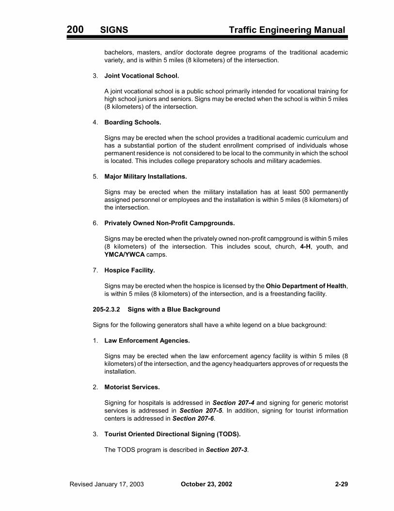
200 SIGNS Traffic Engineering Manual
October 23, 2002 Revised January 17, 2003 2-29
bachelors, masters, and/or doctorate degree programs of the traditional academicvariety, and is within 5 miles (8 kilometers) of the intersection.
3. Joint Vocational School.
A joint vocational school is a public school primarily intended for vocational training forhigh school juniors and seniors. Signs may be erected when the school is within 5 miles(8 kilometers) of the intersection.
4. Boarding Schools.
Signs may be erected when the school provides a traditional academic curriculum andhas a substantial portion of the student enrollment comprised of individuals whosepermanent residence is not considered to be local to the community in which the schoolis located. This includes college preparatory schools and military academies.
5. Major Military Installations.
Signs may be erected when the military installation has at least 500 permanentlyassigned personnel or employees and the installation is within 5 miles (8 kilometers) ofthe intersection.
6. Privately Owned Non-Profit Campgrounds.
Signs may be erected when the privately owned non-profit campground is within 5 miles(8 kilometers) of the intersection. This includes scout, church, 4-H, youth, andYMCA/YWCA camps.
7. Hospice Facility.
Signs may be erected when the hospice is licensed by the Ohio Department of Health,is within 5 miles (8 kilometers) of the intersection, and is a freestanding facility.
205-2.3.2 Signs with a Blue Background
Signs for the following generators shall have a white legend on a blue background:
1. Law Enforcement Agencies.
Signs may be erected when the law enforcement agency facility is within 5 miles (8kilometers) of the intersection, and the agency headquarters approves of or requests theinstallation.
2. Motorist Services.
Signing for hospitals is addressed in Section 207-4 and signing for generic motoristservices is addressed in Section 207-5. In addition, signing for tourist informationcenters is addressed in Section 207-6.
3. Tourist Oriented Directional Signing (TODS).
The TODS program is described in Section 207-3.

200 SIGNS Traffic Engineering Manual
October 23, 2002 Revised January 16, 20042-30
205-2.3.3 Signs with a Brown Background
Permanent signs may be erected for the following generators provided: (1) the generator isa publicly owned or a privately owned non-profit facility; and (2) the generator has an annualattendance of 100,000 plus 10,000 per mile in urban areas, or 50,000 plus 5,000 per mile inrural areas, where the distance is measured from the generator to the intersection. In ruralareas, where generators are less common and more space for generator signing is available,attendance requirements may be reduced by up to 60 percent by the District DeputyDirector. Signs for these generators shall have a white legend on a brown background:
1. Miscellaneous Generators - Arenas, coliseums, stadiums, auditoriums, conventionhalls, fairgrounds, parks (national, state, county, municipal, etc.), race tracks and zoos.
2. Recreation Areas - Recreation areas (e.g., beaches and lakes). Where recreationalareas are established at a large lake, reservoir or forest and many recreational facilitiesare available, boundaries may be established for the purpose of informing oncomingtraffic. On roadways entering the region, the D7-H3 sign may be erected at theboundary.
3. Tourist Attractions - Aquariums, arboretums, botanical gardens, geological sites,historical sites, state memorials, restorations, monuments, museums, planetariums andother attractions of historic or cultural interest.
Also, permanent signs may be erected for privately-owned major tourist attractions (e.g.,large amusement parks) where the traffic volumes are such as to warrant additional signingto facilitate an orderly flow of traffic to the facility. Signs for these generators shall have awhite legend on a brown background.
205-2.4 Generators That Do Not Normally Warrant Signing
Except as covered in the previous paragraph, activities signed for under the Tourist OrientedDirectional Signing (TODS) program do not qualify for generator signing under this section.
Also, it has been determined that the following facilities do not normally qualify for signing underthese provisions for traffic generators:
1. Businesses - Industrial parks, shopping centers, shopping malls, television stations, radiostations and theaters.
2. Cemeteries - National, local, state, military, public and private.
3. Community Facilities - Churches, civic centers, libraries and subdivisions.
4. Educational - Grade schools and high schools (except as provided in Section 205-2.3.1).
5. Governmental - Courthouses, disaster assistance facilities, civil defense facilities, driverslicense centers, jails, prisons, local government highway buildings, post offices, researchfacilities, experimental facilities.
6. Medical - County homes, fraternal homes, nursing homes, humane facilities (i.e., animalshelters), infirmaries, treatment centers, mental facilities, research facilities, retirementfacilities, sanitariums, veteran facilities.
7. Military - Armories, arsenals, sites and detachments.

200 SIGNS Traffic Engineering Manual
October 23, 2002 Revised January 16, 2004 2-31
8. Recreational - Amusement parks, country clubs and golf courses.
205-3 Weigh Station Signing for Conventional Roads
205-3.1 General
Weigh Station signing for conventional roads is addressed in OMUTCD Section 2D.43 andFigure 2D-3. Four signs, as indicated in OMUTCD Section 2D.43 and Figure 2D-3, shall beused; however, on ODOT-maintained highways, the R13-1 sign shall be replaced with the R13-H1 sign, and the D8-2 sign shall be replaced with the D8-H2 sign. The locations of the four signsshall be as shown in Figure 2D-3.
R13-H1 D8-H2
72 x 36 60 x 30
205-3.2 Exit Direction Sign (D8-H2)
The bottom line of this sign consists of a changeable message panel capable of displaying thewords “OPEN” and “CLOSED”. The legend “CLOSED” shall be displayed when the station isclosed and the legend “OPEN” shall be displayed when the station is open and shall be controlledfrom the scale house.

200 SIGNS Traffic Engineering Manual
October 23, 2002 (January 16, 2004)2-32
Intentionally blank.

200 SIGNS Traffic Engineering Manual
October 23, 2002 Revised January 16, 2004 2-33
206 GENERAL INFORMATION SIGNS
206-1 General
General Information Signs on conventional highways are addressed in OMUTCD Section 2D.47, andfor freeways and expressways these signs are addressed in OMUTCD Section 2E.55. For purposesof the OMUTCD and TEM “conventional” highway basically refers to any non-freeway, non-expressway highway.
The following sections address signs not in the OMUTCD, or provide additional information about theintended use of signs that do appear in the OMUTCD. Figures 298, 5a through 5c illustrate GuideSigns that fall into the general Information Signs category discussed in this section which are notshown in the OMUTCD.
206-2 Reserved for Future Information
This section is reserved for future information.
206-3 Township Limit Signing (I-H2e, E8-H2a)
ORC Section 503.061 requires ODOT to erect Township Limit signs on ODOT-maintained highways,other than freeways and expressways, located within the Township and outside the limits of anincorporated municipality, indicating the boundaries of the Township, when a resolution requestingsigns has been adopted by the Township. The I-H2e sign is used for this purpose.
Although there is no legal requirement to erect signs on freeways and expressways, Districts maydecide, at their discretion, to erect signs on these facilities for townships which have populations inexcess of 5,000 outside of municipal corporation limits. The E8-H2a sign is used for this purpose.
I-H2e E8-H2a
206-4 Signing for Unincorporated Communities (I-H2d)
The Unincorporated Community Name sign (I-H2d) may be erected on ODOT-maintainedconventional highways in accordance with OMUTCD Section 2D.47. Requests should be referredto the local Board of County Commissioners to confirm the spelling and the boundaries of thecommunity. Unincorporated communities which claim to be historically significant should furnishconfirmation from the Ohio Historical Society or a local historical society.
A driver should be able to recognize a change from rural conditions. A community usually has acluster of homes, schools, churches, businesses furnishing motorist services, stores, parking,pedestrians, or other land development. Signs should not be erected where the unincorporatedcommunity name is synonymous with that of a developer, contractor or real estate broker where thesign could be considered an advertisement.

200 SIGNS Traffic Engineering Manual
October 23, 2002 Revised October 17, 20032-34
I-H2d
206-5 Highway Advisory Radio (HAR) Signing (D12-H6, D12-H7, D12-H8, D12-H9)
206-5.1 General
Signing for HAR systems is not specifically addressed in the OMUTCD. The following guidelinesand criteria have been developed based on guidelines issued by FHWA in 1981.
HAR signing may be authorized for systems installed by local jurisdictions or governmentalagencies when the criteria set forth in this section are met, and after receiving approval by theDistrict, as outlined below.
The owner/operator of the HAR system will be responsible for the fabrication, erection andmaintenance of the signs under an Agreement (and Occupancy Permit) with the Director ofTransportation. With a written notice, the Director may require the owner/operator to removesigns that have not been properly installed or maintained.
D12-H6 D12-H7 D12-H8 D12-H9
206-5.2 Guidelines
For situations which cannot be addressed by conventional signing, the following guidelines havebeen established to support a determination for the use of signs to supplement HAR systemsinstalled by local jurisdictions or governmental agencies on high-volume or high-speed roadways.However, these should not be considered the only justification for the erection of this signing.
1. Extraordinary circumstances in one or both of the following categories:
a. Unusual road conditions, including extended construction or maintenance operations,detours, and road emergencies.
b. Traffic and parking advisories - information for traffic destined for specific events (e.g.,World’s Fair) or major traffic generators (e.g., transportation terminals or stadiums).
2. As a component of a traffic surveillance and control system.
206-5.3 Procedures for Approval, Installation and Removal
The following procedure shall be used for approval, installation and removal of an HAR system:

200 SIGNS Traffic Engineering Manual
October 23, 2002 (January 16, 2004) 2-35
1. The owner/operator shall submit a written request to the District including, but not limited to,the following information:
a. Map of the region showing transmitter location, broadcast frequency, area of coverageand route(s) on which signs are requested.
b. A general description of message content, anticipated frequency of message repetitionand message changes, and hours of transmission.
c. Names of persons operating the HAR station and where it is located.
d. Number of signs requested, including approximate location and legend for each sign.
2. The District reviews the information provided and makes a field check to determine if thesystem is eligible and if the signs and locations are appropriate.
3. If approved by the District, an Agreement is prepared (see Form 296-3 for a SampleAgreement) and returned to the owner for review and execution.
4. When the executed Agreement and a copy of the station’s Federal CommunicationsCommission (FCC) license are returned to the District by the owner, the following packageof information is then provided by the District to the owner:
a. Occupancy Permit Application for work in the right-of-way.
b. Sample plan sheets including design information, applicable ODOT specifications andStandard Construction Drawings.
c. Specific sign locations determined by District review of requested sign locations.
5. Owner/operator submits Occupancy Permit Application and construction plans forinstallation of the signs to the District.
6. After approval of the construction plans by the District and issuance of the OccupancyPermit, the owner/operator has the signs installed. The completed installation shall beinspected and approved by the District.
7. The owner/operator shall immediately notify the District of any event or condition which maysignificantly affect its ability to perform in accordance with the provisions of its Agreementwith ODOT.
8. Any modifications or alterations of the signing will require written approval of the Director.
9. As provided in the Agreement, the owner/operator will be responsible for removal of the signsand restoration of the area when the HAR system ceases to operate.
206-5.4 Operational Criteria
The following operational criteria shall apply:
1. Only traffic advisory or directional messages shall be broadcast over the radio station.
2. No message of a commercial or promotional nature may be broadcast at any time.

200 SIGNS Traffic Engineering Manual
October 23, 2002 Revised January 16, 20042-36
3. Messages concerning disruptions of normal traffic flow or road conditions due to highwayconstruction or maintenance activities shall be broadcast when requested by ODOT.
4. The radio station shall be operated at all times in accordance with FCC rules and regulations.
5. The HAR system shall be operated on a permanent year-round basis, twenty-four hours aday unless otherwise approved by the District.
6. The location(s) of the broadcast receptions zone(s) shall not be altered subsequent toplacement of the related signs.
206-5.5 Signing for HAR Systems
The following criteria shall apply when signing has been approved for an HAR system:
1. The design and placement of HAR signs shall be in accordance with standards in theOMUTCD. These signs usually have a white legend on a blue background; however, if usedas work zone or Warning Signs the standard colors shall be used (i.e., black legend with anorange background for work zone situations and a yellow background for warning). The signsand their sizes are shown in the Sign Design Manual (SDM).
2. Signing for an HAR zone normally consists of three signs in each direction of travel: the D12-H6 sign 1 mile in advance of the broadcast zone, the D12-H7 at the beginning of thebroadcast zone and the D12-H9 at the end of the zone. Depending on the circumstances(e.g., length of zone and sign crowding in the area) it may be desirable to erect more thanone of the D12-H7 signs in the broadcast zone and/or not use the D12-H9 sign.
3. Other legend elements such as AIRPORT or VISITORS instead of TRAFFIC may bewarranted.
4. When circumstances warranting the signing are seasonal, the owner/operator shall removeor cover the signs when the HAR system is not in use.
5. When the HAR system is not operated on a twenty-four hour basis, yellow lights which flashwhen the system is operational shall be mounted on the sign at the beginning of thebroadcast zone, and the words WHEN FLASHING shall be added at the beginning of thelegend (D12-H8).
206-6 Carpool Signing (D12-H2)
The availability of rideshare opportunities is publicized with the D12-H2 sign. The local rideshareagency (LRA) is responsible for furnishing all signs to ODOT. The signs shall be fabricated inaccordance with ODOT design standards and material specifications. ODOT will supply the signsupports and necessary hardware. The locations for the signs may be suggested by the localrideshare agency, but must be approved by ODOT prior to installation.
The Districts should maintain the signs. Replacement signs should be obtained from the LRA asneeded.
D12-H2

200 SIGNS Traffic Engineering Manual
October 23, 2002 Revised January 16, 2004 2-37
206-7 Signing for Countywide 9-1-1 Systems (D12-H14)
206-7.1 General
ORC Section 4931.46 indicates that upon installation of a countywide 9-1-1 system, the Boardof County Commissioners may direct the County Engineer to erect and maintain at theCounty boundaries on County Roads and State and Interstate Routes, signs indicating theavailability of a countywide 9-1-1 system. Any sign erected by a County under this section shallbe erected in accordance with and meet the specifications established in section 206-7.2. Allexpenses incurred in erecting and maintaining the signs shall be paid by the County.
For other signing dealing with the 9-1-1 system, see Section 207-7.
206-7.2 Sign Details
ORC Section 4931.46(B)(2) requires the Director of Transportation to develop designspecifications for signs giving notice of the availability of a countywide 9-1-1 system and establishstandards for erection of the signs. Consequently, the N-96 sign was developed. The standardsize for use on conventional streets and highways is 36 x 24 inches (900 x 600 millimeters), andon expressways and freeways the standard size is 60 x 36 inches (1500 x 900 millimeters). TypeG reflective sheeting (CMS Item 730.19) shall be used for the signs.
The signs will be flatsheet material or plywood. SCD TC-52.20 provides information about bolthole spacing for flatsheet signs. The sign blank material, sign supports and mounting hardwareshall conform to CMS Item 730. SCD TC-41.20 provides post information.
D12-H14
206-7.3 Procedure
If a countywide 9-1-1 system exists and the Board of County Commissioners directs theCounty Engineer to erect signs on an ODOT-maintained highway, the County Engineer shallcontact the local ODOT District Office in writing to obtain: (1) approval of the proposed signlocations, and (2) a permit to work within the state right-of-way. The request should includespecific information about the proposed sign locations and a proposed traffic control plan.
Unless the District agrees to another arrangement, the County Engineer shall have theproposed sign locations marked by stake or paint to assist in District review; no paint marks shallbe permitted on the pavement surface. The D12-H14 sign shall be placed for traffic entering theCounty at or near the location where the route crosses the County Line. It should be placed onthe right side of the highway, except that when the existing County Line sign is in the median, the9-1-1 sign(s) may also be placed in the median. Further, the D12-H14 sign is a separateinstallation and shall not be mounted with the County Line sign or any other signs. Existing signsshall not be moved to accommodate placement of the D12-H14 on ODOT-maintained highways.
The District shall field check each proposed site to assure the placement of the signs will be inaccordance with OMUTCD Sections 2A.18, 2A.19, and 2C.23, which establish horizontal andvertical placement criteria, and SCDs TC-42.10 and TC-42.20. If the District concurs with theproposed location and the traffic control plan, the County Engineer may schedule erection of thesign once the permit is approved.

200 SIGNS Traffic Engineering Manual
October 23, 2002 Revised January 16, 20042-38
When the signs have been erected, the District should have the locations checked forcompliance to ODOT standards. All discrepancies will be corrected by the County Engineer.
206-7.4 Maintenance
The County Engineer shall maintain these signs in good condition and shall advise the Districtof who should be contacted for repair or replacement of signs erected on ODOT-maintainedhighways. Damage reports received by ODOT concerning the signs shall be forwarded to theCounty Engineer’s office or a designated contact.
If the County should choose to discontinue the countywide 9-1-1 signing program, the CountyEngineer will notify the District in writing. The County Engineer will be responsible for removingall D12-H14 signs and supports on the state right-of-way.
If D12-H14 signs erected on ODOT-maintained highways become a hazard or nuisance and theproblem is not corrected by the County within a reasonable time, the District shall remove thesigns and supports. The County shall be billed for the work and advised where the sign(s) andsupports can be picked up.
206-8 Memorial Highway/Bridge Signing (E8-H5, D6-H4, D6-H5)
Any street or highway that is part of the State’s highway system may be officially assigned adistinctive name, commemorative of an historical event or personage or a commonly accepted andappropriate name, by which the highway is known. The Office of Traffic Engineering (OTE)maintains a list of named highways on the ODOT-maintained system.
There are three processes by which ODOT-maintained highways can be memorialized or named.They are as follows:
1. The most frequently used process is by legislation. ORC Chapter 5533 contains numerousexamples of action by the legislature to name or memorialize a highway.
2. Where the section of state highway is completely rural, ORC Section 5511.01 allows theDirector, by administrative action, to assign a distinctive name to the highway. (We have,however, been advised that this does not include naming individual bridges.)
3. Local governments may request the naming of a U.S. or State Route that lies within theirboundaries. This is also accomplished by administrative action of the Director, but requiresunanimous agreement of the local governments in accordance with ORC Section 5511.09.Requests from local governments should be submitted to the District for approval. The decisionon approval should be made by the District Deputy Director on behalf of the Director. TheDistrict shall notify OTE of such approvals.
For rural roads that are totally under the maintenance and operational authority of local governments,the Director of Transportation has no involvement in the naming/memorializing process. ORCSections 5541.04 and 5543.04 assign responsibility for naming/memorializing County and TownshipRoads to County officials.
Municipal corporations also do not require action by the Director of Transportation toname/memorialize city streets located totally within their boundary. ORC Section 723.01 grants broadauthority for the control of city streets to the municipality officials, and ORC Section 5511.09addresses the authority of municipal officials to name a portion of the U.S. and State Routes withinthe municipal corporation without action of the Director.

200 SIGNS Traffic Engineering Manual
October 23, 2002 Revised January 16, 2004 2-39
Signing of memorial highways/bridges should be in accordance with OMUTCD Sections 2D.48 and2E.08. Signs for memorial highways established by the legislature in accordance with ORC 5533 orby the Director in accordance with ORC 5511.01 should be furnished and installed by the District.Signs for memorial highways on the U.S. and State Routes established by local governments inaccordance with ORC Section 5511.09 should be furnished and installed by the requesting agencyat locations approved by the District.
The D6-H4 sign is used in rest areas, scenic overlooks and other off-highway locations. The D6-H5sign is used on the mainline of conventional highways. The E8-H5 is a Level III sign used on themainline of freeways and expressways. For sign design details of the D6-H4 and D6-H5 refer to theSign Design Manual (see Section 295-2). For the E8-H5 sign see Figure 298-5C.
D6-H4 D6-H5 E8-H5
206-9 TARGET ENFORCEMENT AREA Sign (D12-H15)
Every six months the Ohio State Highway Patrol (OSHP) produces a list of their high accidentlocations for each patrol post. These locations may be targeted for increased enforcement efforts.
ODOT has agreed to cooperate with the OSHP in posting signs indicating the target enforcementareas. The TARGET ENFORCEMENT AREA sign (D12-H15) is used for this purpose.
Each post will have one location to be marked with these signs. The size of the target enforcementarea is determined by OSHP, and may consist of an intersection or section of highway. The locationmay change every six months.
A sign should be installed on each ODOT-maintained approach to the target enforcement area,including locations on ODOT-maintained highways inside Villages.
D12-H15
206-10 Signing for Over/Underpasses on Freeways and Expressways
Districts may, at their discretion, elect to provide signing on freeways and expressways to identifyroads that pass over or under the mainline. For those Districts that decide to provide such signing,a D3-H2 sign may be ground mounted in advance of the structure. Other signing methods, such asthe use of direct applied sheeting on the bridge beams, can be considered, if acceptable to theDistrict.
Use of this signing is optional and can be selectively applied at over/underpasses in the District.

200 SIGNS Traffic Engineering Manual
October 23, 2002 Revised January 16, 20042-40
206-11 Drinking Water Protection Area Signs (I-H15)
The Ohio Environmental Protection Agency (Ohio EPA) has requested that signs be erected todesignate those areas that have been scientifically determined to be contributing ground water topublic drinking water systems serving populations of 500 or more persons. The I-H15 sign has beendeveloped for this purpose.
The I-H15 sign is 36 x 24 inches (900 x 600 millimeters) and blue on white. The sign color wasselected to distinguish this sign from other traffic control signs. The signs are intended to increasepublic awareness, and alert emergency response teams that they are entering a Drinking WaterProtection Area. The clean-up of spills is handled differently in these areas.
The I-H15 sign includes a phone number. The statewide Ohio EPA emergency response phonenumber is 1-800-282-9378. The public drinking water provider will decide what phone number toinclude on the sign. This can be the statewide emergency response number or a local emergencyresponse number (including 9-1-1).
ODOT has agreed to fabricate and erect I-H15 signs at locations where an ODOT-maintainedhighway crosses the five-year time of travel zone for aquifers serving populations of 500 or morepersons. Specific locations for the signs are determined by the Ohio EPA. Signs for locations withinmunicipal corporation limits should be provided and erected by the municipal corporation.
I-H15
206-12 TOURISM INFO 1-800-BUCKEYE Sign (D7-H6)
The TOURISM INFO 1-800-BUCKEYE sign (D7-H6) is intended for installation as a supplementalpanel below Recreational and Cultural Interest Area (E3-H2) signs to acquaint drivers with the toll-freetourist information telephone number. This sign should be installed on all E3-H2 signs on theInterstate system that do not have another supplemental panel.
D7-H6
206-13 ROAD CONDITIONS 1-888-2-OH-ROAD Sign (D12-H10)
The ROAD CONDITIONS 1-888-2-OH-ROAD sign (D12-H10) is intended for installation as asupplemental panel below existing Highway Patrol (D12-H16) signs to acquaint drivers with the toll-free weather and highway construction telephone number. These panels should be installed on allD12-H16 signs on freeways and expressways that do not already have supplemental panels.
D12-H10

200 SIGNS Traffic Engineering Manual
October 23, 2002 Revised January 16, 2004 2-41
206-14 Community Recognition Signing
Periodically, communities desire signing for the purpose of recognizing a local achievement, such asa state high school championship athletic team or an award it has received from a professionalorganization. This signing does not provide pertinent information to drivers to enable them to performtheir driving task, nor does it meet the basic principles for traffic control devices outlined in theOMUTCD. To control proliferation of this type of signing along the rights-of-way of ODOT-maintainedhighways, the following guidelines should be used when determining whether a community that hasrequested such signing should receive it.
Under Ohio law, state route extensions within municipal corporations are the responsibility of the localauthority. ODOT does not endorse installation of Community Recognition Signing on such extensions,nor does it accept any responsibility for such signs. However, ODOT generally does not questiondecisions made by local authorities regarding signs erected thereon. As such, those requestingCommunity Recognition signing should be referred to the local authority. If the authority agrees toerect this signing inside the municipality, the requesting community is responsible for obtaining thesigning. In addition, any such signing should not be erected on Community Name signs (I-H2a or I-H2d). Furthermore, it is recommended that only one such sign be erected on a particular state routeextension into a municipality.
Similarly, ODOT does not generally endorse installation of signing recognizing a County’sachievement on ODOT-maintained highways except when approved by the County Commissionersand the District office. When this occurs, such signing may be installed on County Line signs (I-H2f,I-H2g) by the District office after the sign’s design has received the approval of the District DeputyDirector. Only one Community Recognition sign should be erected on any I-H2f or I-H2g sign.
The ODOT Sign Shop will normally not fabricate Community Recognition signs. Also, these signsshall not be installed on Interstates or other freeways.
206-15 Reference Marker Sign (D10-H4, D10-H4a)
The Reference Marker sign should be used on all non-Interstate ODOT-maintained highways. Thesesigns give the distance in miles along the route, and should be installed in accordance with themileages contained in the ODOT Straight Line Diagrams.
The signs may be single faced for mounting on both sides of the road. For mounting on one side ofthe road, the signs may be double faced or mounted back to back. Where physical restrictionsprevent the installation of the D10-H4 sign at the even mile, the D10-H4a sign may be used with theD10-H4 sign indicating the distance in hundredths of a mile that the sign is located from the properlocation.
The D10-H4 signs should be mounted at a minimum height above the pavement edge of 4 feet (1.2meters).
D10-H4 D10-H4a

200 SIGNS Traffic Engineering Manual
October 23, 2002 (January 16, 2004)2-42
Intentionally blank.

200 SIGNS Traffic Engineering Manual
October 23, 2002 Revised January 16, 2004 2-43
207 GENERAL SERVICE SIGNS
207-1 General
Motorist Services Signs on conventional highways are addressed in OMUTCD Section 2D.44,andfor freeways and expressways these signs are addressed in OMUTCD Section 2E.51. For purposesof the OMUTCD and TEM “conventional” highway basically refers to any non-freeway, non-expressway highway. Figures 298-5b and 298-5d include illustrations of Motorist Services typeGuide Signs discussed in this section which are not shown in the OMUTCD.
The following sections address signs not in the OMUTCD, or provide additional information about theintended use of signs that do appear in the OMUTCD.
207-2 LOGO (Specific Service) Program
207-2.1 General
LOGO (Specific Service) signs are addressed in the OMUTCD Chapter 2F. The Ohio LogoSigning Program established by ODOT, also known as the Specific Service Sign Program,permits eligible businesses which provide gas, food, lodging, camping or attraction services todrivers to have their logos placed on specific service (logo) signs. Mainline logo signs are placedin advance of eligible interchanges, and directional logo signs are also placed along the exitramps.
Logo program documents that define the logo program adopted by ODOT are available uponrequest from the Office of Traffic Engineering. Two document packages exist, one forinterchanges on the Interstate system and one for interchanges on multi-lane divided non-Interstate highways. Generally, each document package contains the following: (1) Contract withProgram Manager; (2) Program Administrative Rules and Regulations; (3) SigningStandards and Guidelines; (4) Ohio Revised Code Section 4511.101 and 5516.02; and (5)ODOT SOP PH-P-403, Permits to Use or Occupy Highway Rights-of-Way.
207-2.2 District Procedures and Responsibilities
District procedures to be followed are contained in the documents referred to in Section 207-2.1.District responsibilities include, but are not necessarily limited to, the following:
1. Approve work plans for each interchange.
2. Approve relocation of exiting signs to accommodate specific service signs.
3. Provide written notice to the Program Manager to remove or relocate logo signs due to othernecessary non-specific service sign or a highway improvement project.
4. Remove the danger when any specific service sign, logo sign panel or support becomes, oris in danger of becoming, a clear and present danger to the public, and the ProgramManager is unavailable.
5. Notify the Program Manager of needed relocations or removal of specific service signing.
207-2.3 Central Office Procedures and Responsibilities
Central Office procedures to be followed are also contained in the documents referenced in

200 SIGNS Traffic Engineering Manual
October 23, 2002 Revised January 16, 20042-44
Section 207-2.1. Central Office responsibilities include, but are not necessarily limited to, thefollowing:
1. Approve the Program Manager’s advertising agreement.
2. Approve the general plans for work zone traffic control.
3. Review and approve logo designs, including alternative fuel legends or symbols.
4. Approve form and content of consent legislation drafted and processed by ProgramManager.
5. Approve “bumping” occurrences.
207-3 TODS Program
207-3.1 General
Tourist-Oriented Directional signs (TODS) are addressed in the OMUTCD Chapter 2G. Thissection describes the Ohio Tourist-Oriented Directional Signs (TODS) Program as establishedby ODOT. This program permits eligible tourist oriented activities to be identified on directionalsigns established for the program. These signs are placed in advance of intersections on ODOT-maintained highways, but not at interchanges on freeways and expressways.
The following documents, available upon request from the Office of Traffic Engineering, definethe TODS program, including the procedures, standards and guidelines: (1) Contract withProgram Manager; (2) Program Administrative Rules and Regulations; (3) SigningStandards and Guidelines; (4) ORC Sections 4511.102 to 4511.107; and (5) ODOT SOP PH-P-403, Permits to Use or Occupy Highway Rights-of-Way.
207-3.2 District Responsibilities
The documents referenced in Section 207-3.1 outline the responsibilities assigned to theDistricts. They include, but are not necessarily limited to, the following:
1. Approving advanced signing at an intersection.
2. Providing construction project information to the Program Manager.
3. Approving work plan for each intersection.
4. Removing the danger when any TODS installation becomes, or is in danger of becoming, aclear and present danger to the public and the Program Manager is unavailable .
5. Notifying Program Manager of needed relocations or removal of TODS signing.
6. Determining which existing ODOT-maintained signs will continue to be maintained at eachintersection prior to the Program Manager marketing the program at that intersection.
7. Determining where safety or operational features preclude sign installation.
207-3.3 Central Office Responsibilities
The documents referenced in Section 207-3.1 also outline Central Office responsibilities for this

200 SIGNS Traffic Engineering Manual
October 23, 2002 Revised January 16, 2004 2-45
program. They include, but are not necessarily limited to, the following:
1. Extending, modifying or terminating the contract as needed.
2. Approving the Program Manager’s advertising agreement.
3. Approving the general plans for the work zone traffic control.
4. Approving all forms, applications, agreements and other documents necessary for carryingout the program.
5. Coordinating the review of proposed non-standard symbols and submitting to the FHWA.
6. Canceling individual advertising agreements with reasonable cause.
207-4 Emergency Hospital Signing (D9-2, D12-H17, D12-H17a)
207-4.1 General
Hospital service signs should be erected for hospitals that meet the requirements of Section 207-4.3. Signs may be erected by ODOT for the following types of routes:
1. Interstate Routes inside and outside of corporation limits.
2. Freeways and expressways outside of corporation limits.
3. Other National Highway System (NHS) routes (Section 130-5) outside of corporation limits.
207-4.2 Procedures for Reviewing Requests
In order to avoid a proliferation of hospital service signs, the following limitations shall apply:
1. On Interstate Routes within corporation limits, not more than one hospital should be signedin each direction of travel for each route. The intent is that a driver traveling through amunicipality on an Interstate Route will see service signing for not more than one hospital.
2. On numbered routes that bypass a municipality, not more than one hospital should be signedin each direction of travel for each route. The intent is that a driver bypassing a municipalityon a numbered route will see service signing for not more than one hospital.
When two or more hospitals fulfill the requirements for signing, preferences should be based onhow each hospital fulfills the “physician on duty” requirement in Section 207-4.3 and accessibilityfrom the numbered route.
When non-Interstate numbered routes enter municipalities, signing will normally not be erectedby ODOT since the most appropriate interchange (intersection) for signing is usually inside thecorporation limits.
Signing will normally not be erected on NHS routes when the hospital is located adjacent to thehighway.
ODOT will erect necessary trailblazing signs on numbered routes outside the corporation limits.Local officials shall furnish, erect, and maintain necessary trailblazing signs that conform to theOMUTCD within their jurisdiction. The District shall not erect signs until necessary trailblazing

200 SIGNS Traffic Engineering Manual
October 23, 2002 Revised January 16, 20042-46
signs have been erected by local authorities having jurisdiction over the roadway.
207-4.3 Criteria for Emergency Hospital Signing
The hospital shall operate an emergency care facility twenty-four hours a day, seven days a weekwith a physician on duty at all times. A “physician on duty” is defined as follows:
1. Physician on duty within the emergency department, or
2. Registered nurse on duty within the emergency department with a physician in the hospitalon call, or
3. Registered nurse on duty within the emergency department with a physician on call from hisoffice or house.
The hospital shall be located within 5 roadway miles (8 roadway kilometers) of the interchangeor intersection where signing is initiated.
To qualify as a hospital, based on criteria from the Ohio Department of Health, the facility musthave hospital beds available.
207-4.4 Signing
Signing for hospitals should be in accordance with OMUTCD Section 2D.44 for conventionalroads, and OMUTCD Section 2E.51 for freeways and expressways.
The name of the hospital shall not be included on the signs.
When trailblazing signs are required, they shall consist of the D9-2 sign (hospital symbol sign)and an arrow plate.
207-5 Generic General Service Signing
207-5.1 General
The TODS and LOGO programs discussed in Sections 207-2 and 207-3, respectively, addresssigning for various fuel, food, lodging and camping facilities. See those sections for details ofthose programs.
This section establishes guidelines and criteria for the use of generic General Service signingfor fuel (gas, diesel), food, lodging and camping. However, this standard does not apply toprivately-owned, non-profit campgrounds which are addressed in Section 205-2.
For purposes of this discussion, the term “non-profit” also refers to facilities or organizationsdescribed as “not for profit”.
207-5.2 Guidelines
The following guidelines shall be used in determining when to use generic General Servicesigning:
1. Generic General Service signing should only be provided for facilities meeting the criteriaestablished in Section 207-5.3.
2. Under the terms of Ohio’s TODS program contract (Section 207-3), certain food, lodging

200 SIGNS Traffic Engineering Manual
October 23, 2002 Revised January 16, 2004 2-47
and camping establishments may be eligible for TODS signing in advance of intersectionson U.S. and State Routes. Fuel establishments are not eligible for this program.
New generic General Service signs for fuel, and those food, lodging and campingestablishments not eligible for the TODS program, are not normally warranted atintersections on U.S. and State Routes.
However, existing generic General Service signs for fuel, food, lodging and camping mayremain in place until they have reached the end of their effective performance life, or until thefacilities have been signed for under the TODS program, if eligible.
3. Signing for fuel, food, lodging and camping at interchanges on the Interstate system shouldbe in accordance with the Specific Service Signing (LOGO) program described in Section207-2. Generic General Service signing for fuel, food, lodging or camping at interchangeseligible for LOGO signing is only warranted for a specific type of service when none of thattype of service is signed for with LOGO signing at that interchange and the criteria in Section207-5.3 are met. Interchanges on the Interstate system not eligible for LOGO signing wouldnormally not be eligible for generic General Service signing for fuel, food, lodging andcamping.
4. Signing for fuel, food, lodging and camping at interchanges on expressways and non-Interstate state freeways should be in accordance with the Specific Service Signing (LOGO)program described in Section 207-2. Under the terms of Ohio’s LOGO program contract withthe LOGO Program Manager, existing generic General Service signing for fuel, food,lodging or camping at interchanges eligible for LOGO signing are to be removed by theProgram Manager. Interchanges on these roadways not eligible for LOGO signing wouldnormally not be eligible for generic General Service signing for fuel, food, lodging andcamping.
5. Generic General Service signs for fuel, food, lodging and camping are not normallywarranted in urban areas.
6. Generic General Service signs for fuel, food, lodging and camping should only be erectedwhere the driver can directly return to the highway and continue in the same direction oftravel.
7. The erection of signs for general services shall be in accordance with standards for sign type,height, lateral placement and location as specified in the OMUTCD Section 2A.
8. Signs for General services shall not be erected when the proposed signs would conflict withexisting primary Guide Signs or other traffic control devices. Therefore, no commitmentshould be made to erect signs until an on-site inspection has been conducted at theproposed sign location in order to determine that sufficient space exists.
9. ODOT shall not erect signs until necessary trailblazing signs off the state system have beenerected by others.
207-5.3 Criteria
Specific criteria have been established for generic General Service signing, depending on thetype of service:

200 SIGNS Traffic Engineering Manual
October 23, 2002 (January 16, 2004)2-48
1. Fuel
a. Is located within 3 miles (4.8 kilometers) of the highway for which signing is sought.
b. Provide vehicle services to include fuel, oil and water.
c. Provide public restroom facilities and drinking water.
d. Be in continuous operation for at least sixteen hours a day, seven days a week, all weeksof the year.
e. Provide a public telephone.
2. Food
a. Is located within 3 miles (4.8 kilometers) of the highway for which signing is sought.
b. Provide seating capacity for twenty-four or more persons.
c. Serve meals for at least twelve consecutive hours, six days a week.
d. Display a valid permit from the Ohio Department of Health or appropriate public agencyas required by law.
e. Provide a public telephone.
3. Lodging
a. Is located within 3 miles (4.8 kilometers) of the highway for which signing is sought.
b. Provide eight or more units of overnight accommodations, each unit consisting of at leasta sleeping room and bathroom.
c. Be in continuous operation twenty-four hours a day, seven days a week, all weeks of theyear.
d. Possess a valid permit from the appropriate public agency, as required by law.
e. Provide a public telephone.
4. Camping
a. Is located within 3 miles (4.8 kilometers) of the highway for which signing is sought. Ifwithin the 3 mile (4.8 kilometers) limit no campground is available, the distancerequirement may be extended in 3 mile (4.8 kilometers) increments, up to 15 miles (24kilometers), to allow the first closest eligible campground to be signed.
b. The campground shall provide a minimum of fifty well defined campsites capable ofaccommodating a tent, tent-trailer, pickup camper, travel trailer or motor coach.
c. The access road to the campground shall have an adequate all-weather surface suitablefor safe operation of a motorized vehicle and camping trailer.
d. The campground shall not be operated on a “reservation only” basis.
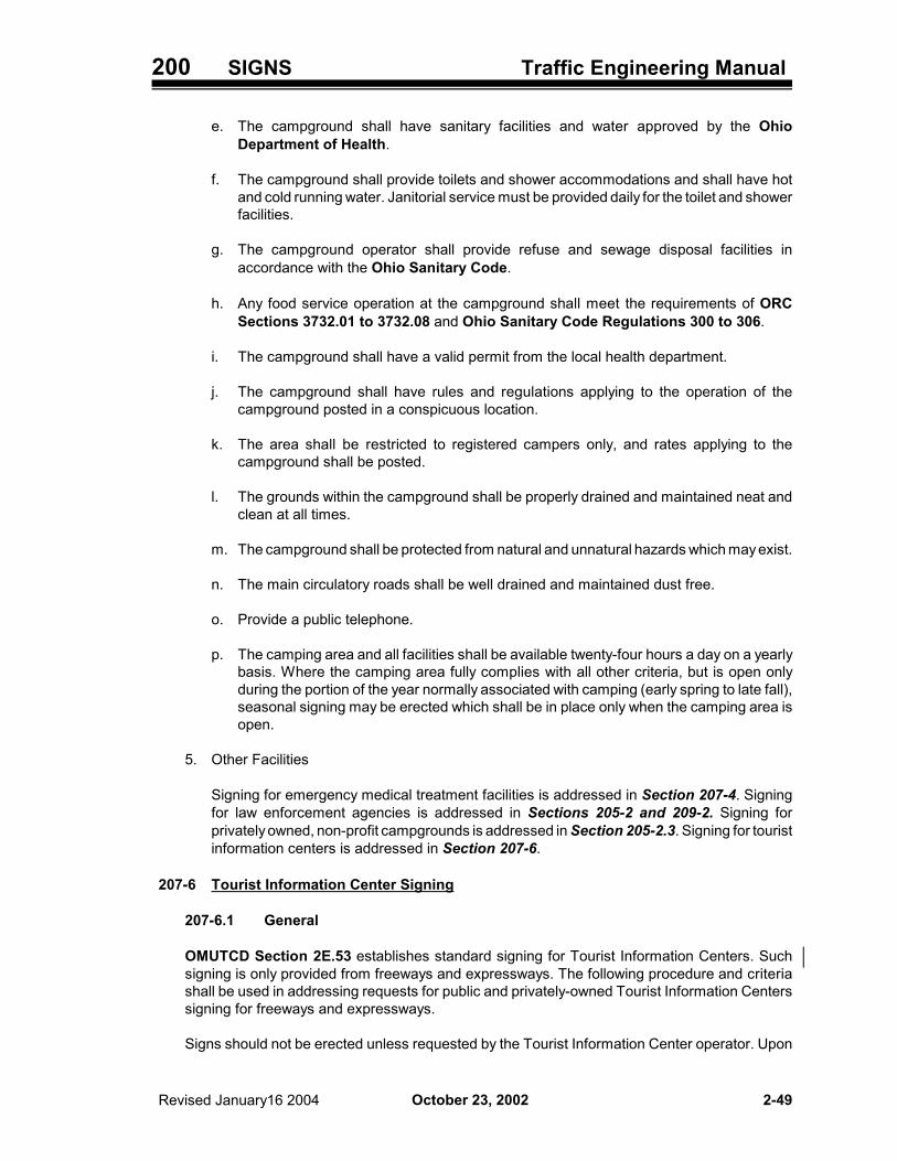
200 SIGNS Traffic Engineering Manual
October 23, 2002 Revised January16 2004 2-49
e. The campground shall have sanitary facilities and water approved by the OhioDepartment of Health.
f. The campground shall provide toilets and shower accommodations and shall have hotand cold running water. Janitorial service must be provided daily for the toilet and showerfacilities.
g. The campground operator shall provide refuse and sewage disposal facilities inaccordance with the Ohio Sanitary Code.
h. Any food service operation at the campground shall meet the requirements of ORCSections 3732.01 to 3732.08 and Ohio Sanitary Code Regulations 300 to 306.
i. The campground shall have a valid permit from the local health department.
j. The campground shall have rules and regulations applying to the operation of thecampground posted in a conspicuous location.
k. The area shall be restricted to registered campers only, and rates applying to thecampground shall be posted.
l. The grounds within the campground shall be properly drained and maintained neat andclean at all times.
m. The campground shall be protected from natural and unnatural hazards which may exist.
n. The main circulatory roads shall be well drained and maintained dust free.
o. Provide a public telephone.
p. The camping area and all facilities shall be available twenty-four hours a day on a yearlybasis. Where the camping area fully complies with all other criteria, but is open onlyduring the portion of the year normally associated with camping (early spring to late fall),seasonal signing may be erected which shall be in place only when the camping area isopen.
5. Other Facilities
Signing for emergency medical treatment facilities is addressed in Section 207-4. Signingfor law enforcement agencies is addressed in Sections 205-2 and 209-2. Signing forprivately owned, non-profit campgrounds is addressed in Section 205-2.3. Signing for touristinformation centers is addressed in Section 207-6.
207-6 Tourist Information Center Signing
207-6.1 General
OMUTCD Section 2E.53 establishes standard signing for Tourist Information Centers. Suchsigning is only provided from freeways and expressways. The following procedure and criteriashall be used in addressing requests for public and privately-owned Tourist Information Centerssigning for freeways and expressways.
Signs should not be erected unless requested by the Tourist Information Center operator. Upon

200 SIGNS Traffic Engineering Manual
October 23, 2002 (January 16, 2004)2-50
receipt of a request, the District’s designee should visit the center to check for compliance withthe following criteria. Signs shall not be erected unless the criteria noted in Section 207-6.2 aremet and the District recommends signing for the Tourist Information Center.
If a local Tourist Information Center meets the criteria, except that the information availablepertains only to the local area, signing may be provided at the discretion of the District. Thesecenters shall be signed for as described herein, except that the sign legend should be revised toread LOCAL TOURIST INFO CENTER.
207-6.2 Criteria for Signing
When evaluating a request for Tourist Information Center signing on a freeway or expressway,the following criteria shall apply:
1. The Tourist Information Center shall be located either:
a. Within a rest area on a freeway or expressway, or
b. Within 1 mile (1.6 kilometer) of a freeway or expressway interchange.
2. The Tourist Information Center shall be open or in continuous operation at least eight hoursa day, seven days a week. If operated on a seasonal basis, signs indicating TOURIST INFOshall be removed or covered during the off-season.
3. Unless approved by the District Deputy Director, the Tourist Information Center shall notbe located within a building, or on the same property, as a building used for the primarypurpose of selling services to the motoring public.
4. The center shall have an adequate number of free parking spaces for automobiles with andwithout trailers, campers and motor homes. If located within an urban area, a turnaroundshall be available to accommodate trailers, campers and motor homes.
5. The center shall provide, or be located adjacent to, well-maintained public restroom facilities.
6. The center shall provide, or be located adjacent to, at least one public telephone.
7. A privately-owned center should be endorsed by local authorities and/or civic organizations.
8. Information available to tourists should normally include, but is not limited to, the following:
a. Local Tourist Services - Hotels, motels, restaurants, churches, hospitals with twenty-fourhour emergency services and camping facilities.
b. Local and Regional Points of Interest - Cultural locations, historical sites andgeographical landmarks.
c. Local and Regional Attractions - Recreation areas, amusement parks, festivals and fairs,concerts, outdoor dramas, state parks and national parks.
9. It is desirable, but not mandatory, that facilities for Tourist Information Centers located off offreeways and expressway include the following:
a. Benches and picnic tables on the lawn,
200 SIGNS Traffic Engineering Manual
October 23, 2002 Revised January 16, 2004 2-51
b. Feminine napkin vendor in the women’s restroom, and
c. Sanitary drinking water.
10. The Tourist Information Center may be either a manned or self-service facility.
207-6.3 Signing for Centers on Freeways and Expressways
In general, if the Tourist Information Center meets the criteria in Section 207-6.2 and isrecommended for signing by the District, the center shall be signed in accordance withOMUTCD Sections 2E.51 and 2E.53.
If the Tourist Information Center is located within a rest area the following shall apply:
1. If the rest area signing is in place, a supplemental panel with the legend TOURIST INFOCENTER (D5-H12) or TOURIST INFO (D5-H12a) should be attached above the Rest AreaAdvance sign (D5-1) and above the Rest Area Exit Direction sign (D5-2 or D5-H2a). Thewidth of the supplemental panel (D5-H12 or D5-H12a) should not be wider than the existingsigns. Alternatively, the Tourist Information symbol (D9-10) may be appended beneath theRest Area Advance sign.
2. If the signing for the Tourist Information Center is to be erected as part of the initial rest areasigning, either of the following signing methods may be used:
a. Erect D5-1 and D5-H2a (or D5-2) signs with the TOURIST INFO CENTER (D5-H12) orTOURIST INFO supplemental panel (D5-H12a); or
b. Erect the D5-H8 and D5-H8a (or D5-H9) signs.
The D5-H8 sign has the legend REST AREA TOURIST INFO CENTER xx MILES. TheD5-H9 sign has the legend REST AREA TOURIST INFO CENTER �. The D5-H8a signhas the legend REST AREA TOURIST INFO CENTER NEXT RIGHT.
The D5-H8 and D5-H8a (or D5-H9) signs may also be erected if the existing rest areasigns are being replaced because of safety upgrading, sign damage or deterioration.Serviceable rest area signs should not be replaced with D5-H8 and D5-H8a (or D5-H9)signs solely for the purpose of adding the TOURIST INFO CENTER or TOURIST INFOlegend.
3. The D5-H8 and D5-H8a (or D5-H9) sign shall not be erected for Tourist Information Centerswhich operate on a seasonal basis.
207-6.4 Signing for Centers Off the Freeway or Expressway
For a Tourist Information Center located off the freeway or expressway, the following additionalprovisions shall apply:
1. If a Multiple General Services sign (D9-H17) is in place for the interchange, a TouristInformation symbol (D9-10) should be added to the sign. If space is not available to add thesymbol, a larger Multiple General Services sign may be installed.
2. If no Multiple General Services sign is in place at the interchange, the Tourist Informationsymbol (D9-10) may be appended to ground mounted interchange guide signs. Alternatively,a Tourist Information Center word message sign (D5-H12b) may be erected.

200 SIGNS Traffic Engineering Manual
October 23, 2002 Revised January 16, 20042-52
3. Tourist Information symbol signs (D9-10) with appropriate arrow plates (I-H12) should beerected:
a. On multi-lane ramps, and
b. At the end of a ramp when the Tourist Information Center is not within sight of theinterchange.
4. Signs shall not be erected by ODOT for Tourist Information Centers located off the stateright-of-way until the operator or appropriate local authorities have provided, at other thanstate expense, any additional signing necessary to direct tourists to the center.
5. ODOT shall not erect trailblazing signs on city streets, or County or Township roads.
207-7 Motorist Assistance Signs (D12-H11, D12-H12)
NEED HELP? 1-877-7-PATROL signs (D12-H11) were installed by ODOT at 153 locations on ODOT-maintained highways in early 1999. These signs were installed at the request of the Ohio StateHighway Patrol (OSHP), to publicize their toll-free phone number. This phone number is intendedfor non-emergency calls.
In mid-1999, the EMERGENCY CALL 911 signs (D12-H12) were installed by ODOT as supplementalpanels with the D12-H11 signs. These signs, also installed at the request of OSHP, were to reminddrivers to call 9-1-1 in an emergency. The D12-H12 signs were installed in all counties with 9-1-1service. Counties without 9-1-1 service at the time were Hocking, Meigs, Monroe, Morgan, Noble,Vinton and Washington Counties in District 10, and Carroll, Columbiana and Harrison Countiesin District 11.
OSHP provided funding for initial sign fabrication. The Districts provided the materials and labor forinstallation.
No funding has been provided by OSHP to cover fabrication costs of signs needed for maintenancereplacements. The Districts should order and install replacement signs as needed using establishedprocedures.
With this signing program, use of the N-92 signs (HIGHWAY PATROL MONITORS CB 9 ANDCELLULAR 911) was discontinued.
D12-H11 D12-H12
The D12-H14 sign also deals with the 9-1-1 system (See Section 206-7).

200 SIGNS Traffic Engineering Manual
October 23, 2002 Revised January 16, 2004 2-53
208 REST AREA SIGNS
208-1 General
The OMUTCD addresses signing for rest areas in Sections 2D.41 and 2E.52. Additional signing hasbeen developed over the years for use in ODOT rest areas. For the most part, these address specificrequests from the Department of Public Safety (ODPS) or the offices responsible for maintainingthe facilities. This section addresses additional signing approved for use in advance of, and within restareas. Figures 298-6a through 298-6c illustrate Rest Area Signs discussed in this section which arenot shown in the OMUTCD.
208-2 REST ROOMS CLOSED Sign (D5-H33)
The REST ROOMS CLOSED sign (D5-H33) shall be erected on conventional roads and on themainline of freeways and expressways when rest rooms are closed for other than routinemaintenance of short duration. This sign should be erected under the Advance Rest Area sign (D5-1or D5-H1). On freeways and expressways, an additional sign may be erected under the Exit DirectionRest Area sign (D5-2 or D5-H2a).
If the rest area signs are supplemented with panels, the D5-H33 sign should be erected under thebottom panel. If the sign support has a breakaway connection, care must be taken to assure that theD5-H33 sign does not interfere with the breakaway action.
Code No. Route Type Legend SizeInch (mm)
D5-H33 Freeway &Expressway REST ROOMS
CLOSED
48 x 48 (1200 x 1200)
D5-H33 Standard &Major Standard 24 x 24 (600 x 600)
208-3 SAFETY BREAK FREE COFFEE Sign (D5-H16)
The SAFETY BREAK FREE COFFEE sign (D5-H16) may be erected when authorized by the DistrictDeputy Director. These signs shall not be easel-mounted and should not be erected on separatesupports under normal conditions. If the D5-H16-144 sign is used, extreme care must be taken toassure that it does not interfere with the breakaway (or yielding) aspect of the supports and that thesupports are of sufficient size to accommodate the extra signing area and wind loading.

200 SIGNS Traffic Engineering Manual
October 23, 2002 Revised January 16, 20042-54
Code No. Route Type Legend Sizeinch (mm)
D5-H16-48 All SAFETY BREAK FREE COFFEE 48 x 60 (1200 x 1500)
D5-H16-108 Expressway SAFETY BREAK FREE COFFEE / PHONE 108 x 36 (2700 x 900)
D5-H16-132 Freeway SAFETY BREAK FREE COFFEE / PHONE 132 x 48 (3300 x 1200)
D5-H16-144 Freeway & Expressway
SAFETY BREAK FREE COFFEE 144 x 48 (3600 x 1200)
208-4 NO FACILITIES Sign Panel (D5-H17)
The NO FACILITIES panel (D5-H17) may be used on freeways and expressways when a rest areais constructed with the rest room facilities to be added at a later date. This panel is erected below theAdvance Rest Area sign (D5-1). An additional panel may be erected below the Exit Direction RestArea sign (D5-2 or D5-H2a).
Code No. Route Type Legend Sizeinch (mm)
D5-H17 Freeway & Expressway NO FACILITIES 72 x 36
(1800 x 900)
208-5 Other Rest Area Signs
Additional approved signs for use within the rest area are shown in Figures 298-6a through 298-6c.Color and size information can be obtained by referring to the SDM (see Section 295-2).
208-6 Report Drunk Drivers Sign (D12-H13)
The D12-H13 sign is intended to assist the Ohio Department of Public Safety’s campaign toencourage reporting of drunk drivers. The legend on this sign is REPORT DRUNK DRIVERS 1-800-GRAB DUI CELLULAR DIAL *DUI FREE AIR TIME.
This sign should be erected in all ODOT rest areas. It should be erected on separate supports alongthe ramp exiting the rest area when possible, but may be erected elsewhere in the rest area if space

200 SIGNS Traffic Engineering Manual
October 23, 2002 Revised January 16, 2004 2-55
is unavailable along the ramp.
D12-H13

200 SIGNS Traffic Engineering Manual
October 23, 2002 (January 16, 2004)2-56
Intentionally blank.

200 SIGNS Traffic Engineering Manual
October 23, 2002 Revised January 16, 2004 2-57
209 FREEWAY & EXPRESSWAY DISTANCE & DESTINATION SIGNS
209-1 General
Freeway and expressway Distance and Destination Signs are addressed in OMUTCD Sections 2E.01through 2E.50. The following sections address signs not in the OMUTCD, or provide additionalinformation about the intended use of signs that do appear in the OMUTCD.
209-1.1 Freeway and Expressway Guide Sign Design
The OMUTCD provides information regarding the design of freeway and expressway guide signs.Under the “Option” in Section 2E.01, an alternative method is referenced. This method is basedon the Level of Signing concept that has been used by ODOT for many years, and is describedin the Sign Design Manual (SDM) Appendix C (Section 295-2).
For ODOT purposed, the alternative Guide Sign method described in SDM Appendix C (Section295-2) shall be used in designing freeway and expressway guide signs for use on ODOTmaintained highways. This applies to all freeway and expressway guide signs for use on ODOTmaintained highways, whether designed by ODOT or consultant, or fabricated by the ODOT SignShop or private sign fabricator.
209-2 Signing for Generators at Interchanges on Freeways & Expressways
209-2.1 General
This section establishes criteria for determining when a destination qualifies as a traffic generatorfor which Guide Signs, typically containing the name of the generator, may be erected atinterchanges on freeways and expressways.
209-2.2 Participation Within a Municipality
Within the corporation limits of a municipality, ODOT’s involvement with generator signing shallonly occur in the following ways:
1. On Interstate Routes, in conformance with the provisions of SOP OPS-111, ODOT will furnishsigning for eligible traffic generators. The municipality is responsible for acquiring necessarydata and determining eligibility before requesting signs from ODOT.
2. At interchanges on other freeways and expressways, federal or State funding may participatein the costs of furnishing or installing generator signing as part of a highway improvement.The signing must meet the generator signing criteria established by local authorities which,in turn, must be in substantial agreement with the criteria contained herein (see OMUTCDSection 2E.55 and Chapter 2H).
209-2.3 Procedures for Reviewing Signing Requests
Signs may be erected at interchanges on freeways and expressways: (1) after a written requesthas been received from the operator of the generator (with all data necessary to determineeligibility) and an investigation by the District has confirmed the eligibility of the generator asdefined by this standard; or (2) after receipt of a written request from local authorities for generatorsigns on an Interstate Route within a municipality where the requirements of Section 209-2.2. aresatisfied.

200 SIGNS Traffic Engineering Manual
October 23, 2002 Revised January 16, 20042-58
The design and erection of signs for eligible generators shall be in accordance with standards forsign type, height, lateral placement and location as specified in the OMUTCD. The signs typicallycontain the name of the generator, and are typically classified as supplemental guide signs. Asnoted in OMUTCD Section 2E.32, supplemental Guide Signs may show one or two destinationsnot shown on the major Guide Signs. However, only one supplemental Guide Sign should be usedon each interchange approach.
Signs for eligible generators shall not be erected when the proposed signs would conflict withexisting primary Guide Signs or other warranted signs. Therefore, no commitment should be madeto erect signs until an on-site inspection has been conducted at the proposed sign location in orderto determine that sufficient space exists.
Generator signs should normally not be erected at freeway-to-freeway interchanges.Normally, the supplemental Guide Sign for each direction of travel on the mainline should be atthe same interchange. Where it would be more appropriate to erect the generator signs for eachdirection of travel at separate interchanges, this may be done. The operator of the generator mayrecommend an interchange for signing in each direction on the mainline. However, the finaldecision as to sign placement rests with ODOT. Within the corporate limits of a municipality, thisdetermination of sign location shall be coordinated with local authorities.
Under exceptional circumstances, additional signs may be necessary at interchanges on otherfreeways and expressways to adequately sign for an eligible generator. Additional signs shouldbe approved by the District Deputy Director based on an engineering study that documents theneed.
Erection and maintenance of signs which trailblaze from the freeway or expressway interchangeto the generator are the responsibility of ODOT on ODOT-maintained highways, and local officialsfor municipal, County and Township Roads. Generator signs on freeways and expressways shallnot be erected until trailblazer signs are in place.
Not all demands for generator signing can be accommodated. Therefore, the District shoulddevelop a priority system to determine which of the generators should get the limited spaceavailable. If signs for the generator requesting signing would result in too many signs or too manydestinations on a sign, the District shall review the information and determine which generatorswill receive signing. To minimize future conflicts and removals of existing generator signs,consideration should be given to future expectations and priorities of signing at interchangesbefore erecting signs.
209-2.4 Criteria and Eligible Generators
Signs for a traffic generator may be erected on a freeway or expressway when the generatormeets the criteria specified in Table 297-4.
209-2.5 Traffic Generators that Do Not Normally Warrant Signing
Activities signed for under the Specific Service Signing (LOGO) program (Section 207-2) do notqualify for generator signing under this section.
It has also been determined that the following traffic generators do not normally warrant signing:
1. Businesses - Industrial parks, shopping centers, shopping malls, television stations, radiostations and theaters.
2. Cemeteries - National, local, state, military, public and private.

200 SIGNS Traffic Engineering Manual
October 23, 2002 Revised January 16, 2004 2-59
3. Community Facilities - Churches, civic centers, libraries, subdivisions and privately-ownedhistorical facilities.
4. Educational - Grade schools and high schools, except as provided in Table 297-4.
5. Governmental - Courthouses, disaster assistance facilities, civil defense facilities, driverslicense centers, jails, prisons, local government highway buildings, post offices, researchfacilities and experimental facilities.
6. Medical - County homes, fraternal homes, nursing homes, humane facilities (animal shelters),infirmaries, treatment centers, mental facilities, research facilities, retirement facilities,sanitariums and veteran facilities.
7. Military - Armories, arsenals, sites and detachments.
8. Recreational - Country clubs, golf courses, planetariums, fish hatcheries, game farms, gamepreserves, game refuges, arboretums and privately-owned campgrounds.
209-2.6 Signing on Freeways and Expressways for Other Generators
Emergency Hospital signing is addressed in Section 207-4, signing for generic Motorist Servicesis addressed in Section 207-5, and signing for Tourist Information Centers is addressed inSection 207-6. Also, signing for the LOGO Program is described in Section 207-2.
209-3 Control City Destinations for Ohio’s Interstate Highway System
Control cities are major destinations and population centers of national significance, located on or nearthe Interstate Highway System, that have been identified through a process established by AASHTOfor use in guide signing. Each state is involved in the process, and the list is subject to change. Thelist of all control cities in the United States is in the AASHTO publication “List of Control Cities forUse in Guide Signs on Interstate Highways.”
Guide Sign directional and distance information shall be uniformly based on these control cities,instead of presenting a variety of short-range destinations at small mileage intervals that are of littlevalue to the non-local, unfamiliar traveler. Consequently, the number of control cities should be keptto the minimum necessary to provide broad directional information, and they should be used aslegends in the following situations:
1. Interchanges between freeways.
2. Separation points of overlapping freeways.
3. On directional signs on intersecting routes, to guide traffic entering the freeway.
In addition, OMUTCD Section 2E.11 addresses the use of control cities on Pull-Thru (E6-2 or E6-2a)signs and Section 2E.36 addresses their use on the bottom line of Post-Interchange Mileage (E7)signs.
Control cities for loop, spur, outerbelt or innerbelt type facilities should be determined from the linearInterstate Routes to which they connect. Control cities identified for Ohio’s Interstate Highway Systemare listed in Table 297-5.

200 SIGNS Traffic Engineering Manual
October 23, 2002 Revised January 16,20032-60
209-4 Weigh Station Signing for Freeways and Expressways
209-4.1 General
Weigh Station Signing for freeways and expressways is addressed in OMUTCD Section 2E.58and Figure 2D-3. Four signs, as indicated in OMUTCD Section 2E.58 and Figure 2D-3, shallbe used; however, on ODOT-maintained highways, the R13-1 sign shall be replaced with the R13-H1 sign and the D8-2 sign shall be replaced with the D8-H2 sign.
209-4.2 Exit Direction sign (D8-H2)
As noted in OMUTCD Section 2E.58, on Expressways and Freeways this sign shall be erectedat a minimum of 1500 feet (450 m) in advance of the gore. The bottom line consists of achangeable message panel capable of displaying the words “OPEN” and “CLOSED”. The legend“CLOSED” shall be displayed when the station is closed and the legend “OPEN” shall be displayedwhen the station is open and shall be controlled from the scale house.
R13-H1 D8-H2 72 x 36 60 x 30
209-5 Interchange Exit Numbering and Reference Posts
The OMUTCD discusses interchange exit numbering and reference posts in Section 2E.28 and 2E.54,respectively. For ODOT maintained highways, interchange exit numbering and reference posts shallbe used on all routes which are continuous as freeways for their entire length within the State and havea minimum length of 25 miles. For routes which are not continuous as freeways for their entire lengthwith the State, or are continuous as freeways for their entire length within the State but are shorter than25 miles in length, the use of interchange exit numbering and reference posts is not required.

200 SIGNS Traffic Engineering Manual
October 23, 2002 Revised January 16, 2004 2-61
210 MISCELLANEOUS SIGNS
210-1 General
The following sections address miscellaneous signs not in the OMUTCD.
210-2 Extrusheet Sign Identification System
The D10-H7 and D10-H6 signs may be used with extrusheet signs for identification purposes. Thesesigns are typically mounted below the extrusheet sign and used in sign inventories. Sign designs arecontained in the Sign Design Manual (SDM) (see Section 295-2).
The D10-H7 sign is used on the mainline, and includes on the first line the route number with two lettersuffix indicating the route direction (e.g., 71 SB, 30 WB). The second line is the mile marker withaccuracy to nearest hundredth of a mile (e.g., 2.61, 131.04).
The D10-H6 sign is used on the ramps, and includes on the first line the route number with two lettersuffix and “EXIT”. The second line consists of the exit number and one letter ramp location code (e.g.101-J, 80B-K). Table 297-3 and Figure 298-3 describe the one letter ramp location codes. The thirdline is determined by continuing the mainline logging on exit ramps from the point where the rampbegins at the mainline, and by logging backwards up entrance ramps from the point where the rampends at the mainline. Collector-distributors are treated as exit ramps. The intersection of two rampsis treated the same as the intersection of the mainline and a ramp.
The D10-H7 and D10-H6 signs can also be used to establish a freeway or expressway locationidentification system, to facilitate the reporting of accidents for emergency response crews. For thisuse, the signs should be erected as independent installations at periodic spacings of one or two- tenthsmile intervals.

200 SIGNS Traffic Engineering Manual
October 23, 2002 (January 16, 2004)2-62
Intentionally blank.

200 SIGNS Traffic Engineering Manual
October 23, 2002 Revised January 16, 2004 2-63
211 SIGN DESIGN
211-1 General
Detailed information used for the fabrication of highway signs is contained in the Sign Design Manual(SDM) (see Section 295-2). The FHWA counterpart to this manual is the Standard Highway Signs(SHS) manual (see Section 193-11).
Basic information on designable freeway and expressway type Guide Signs is contained in OMUTCDSections 2E.01 through 2E.18. Detailed information is contained in Appendix C of the Sign DesignManual (SDM) (see Section 295-2).
211-2 Sign Design Computer Program
A computerized sign design package is currently in use in the Office of Traffic Engineering. Thisprogram, called SignCAD, greatly simplifies the design of directional Guide Signs. The long range planis to have this program installed in all of the Districts. OTE can assist the Districts in the designingof directional Guide Signs for construction project or force account installation purposes.

200 SIGNS Traffic Engineering Manual
October 23, 2002 (January 16, 2004)2-64
Intentionally blank.

200 SIGNS Traffic Engineering Manual
October 23, 2002 Revised January 16, 2004 2-65
212 SIGN LIGHTING
212-1 General
Sign lighting is addressed in this Section as well as Sections 240-7, 241-4, 242-2 and 1103-6.7.Construction information is addressed in Section 250-8.
212-2 Sign Lighting for Overhead Guide Signs
Sign lighting should be provided for overhead Guide Sign installations reflectorized with Type Fsheeting, and for diagrammatic signs, lane drop signs and left exit signs, reflectorized with Type F orType G sheeting.
Sign lighting should also be provided for all other overhead Guide Signs, except:
1. Where an engineering study has determined that signs have sufficient reflectivity to meet driverneeds without lighting, or
2. In rural areas, where signs installed on tangent roadways have a constant grade approach for atleast 1200 feet (360 meters) prior to the sign, or
3. Where installation would require extending electrical service over 2000 feet (600 meters) to supplythe sign luminaires, or
4. Where signs are fabricated with reflectorized legends, shields and symbols (e.g., route shields,hazardous cargo plaque, airport symbol, arrows, borders) of Type H or Type J reflective sheetingon reflectorized backgrounds of Type G reflective sheeting.
Where two or more signs are supported by the same overhead sign structure, the need for lighting onone sign shall require lighting to be provided for all other overhead signs on that structure.
If it is decided that sign lighting will not be provided or that existing sign lighting will be eliminated, thecriteria used in making the decision should be documented.
212-3 Sign Lighting Fixtures
As noted in Sections 1104-3 and 1130-5, a High Pressure Sodium (HPS) light source is generallyused for lighting ODOT-maintained highways. While HPS lighting provides reasonable colordelineation, it is not usually considered to be best suited for sign lighting. The most commonly usedlight source for exclusive sign lighting in Ohio is mercury vapor. As noted in Section 240-7, mercuryvapor luminaires are the standard on ODOT-maintained highways.

200 SIGNS Traffic Engineering Manual
October 23, 2002 (January 16, 2004)2-66
Intentionally blank.

200 SIGNS Traffic Engineering Manual
October 23, 2002 (January 16, 2004) 2-67
220 MATERIALS AND HARDWARE
220-1 General
Refer to the ODOT Construction and Materials Specifications and Supplemental Specifications(CMS) for details regarding signing materials. Section 241 lists the related CMS references andSections 240 and 250 address additional design and construction information related to signingmaterials and hardware.
220-2 Patented or Proprietary Materials, Specifications or Processes
The use of patented or proprietary materials, specifications or processes is discussed in Section1202-3.
220-3 Purchasing Materials for Installation and Use by Local Agencies
To help encourage uniformity and provide a method whereby local agencies can buy traffic controlmaterials and equipment using federal funds, Sections 1220-4 and 1220-5 describe processes thathave been established whereby local agencies can purchase such items through ODOT.
220-4 Sign Reflectivity
Highway signs utilize reflective sheeting materials containing optical elements designed to return alarge portion of the incident light back towards the source. At night, this property, known asretroreflectivity, redirects incident light from a vehicle’s headlights back toward the vehicle’s occupants.This allows highway signs to remain visible after dark.
The retroreflective properties of highway signs degrade over time, due principally to exposure toultraviolet radiation from the sun and environmental contaminants. Signs that may appear satisfactoryduring the day may have insufficient retroreflectivity to be visible at night. Highway sign retroreflectivityshould be periodically checked to verify its adequacy.
220-5 Sign Reflectivity Inspections
Sign reflectivity should be checked annually using the night driving inspection method. Districts thathave implemented a systematic sign replacement program should not need to conduct reflectivitychecks, provided the replacement intervals are followed and are within the expected performance lifeof the reflective sheeting.
Retroreflectivity can also be measured with a retroreflectometer. However, this is a time consumingand labor intensive method, as it requires that measurements be physically taken with the meter ateach sign. In addition, at this time, the usefulness of the data obtained is questionable, as there arecurrently no established required minimum retroreflectivity levels.
Section 2D-2 of the Traffic Control Devices Handbook (TCDH) (see Section 193-15) describesa method for measuring sign reflectivity. This method uses a two-person crew (driver-observer andrecorder) to drive the roads at night under dim headlight illumination at the posted speed and toevaluate individual signs based on the amount of time that they are visible (legible) to the driver. Signsthat are visible for two seconds or less should be replaced as soon as possible. Signs that are visiblefor three seconds are considered borderline and should be scheduled for replacement. Signs that arevisible for four or more seconds are usually considered acceptable.
The formation of dew or frost on the face of a sign will negatively impact the sign’s retroreflective

200 SIGNS Traffic Engineering Manual
October 23, 2002 Revised January 16, 20042-68
properties. When performing night inspections, evaluators should be aware of this potential condition.Night inspections should only be conducted when atmospheric conditions do not allow the formationof dew or frost on the sign face.
220-6 Use of Reflective Sheeting for Permanent Traffic Control Signs
All permanent traffic control signs shall be reflectorized with Type G reflective sheeting. Reflectorizedlegends on permanent traffic control signs shall be of Type G sheeting. For fluorescent colors whereno Type G material is available, Type H or Type J reflective sheeting may be used. Legends, shieldsand symbols (e.g., route shields, hazardous cargo plaque, airport symbol, arrows, borders) onoverhead Guide Signs may be fabricated with Type H or Type J reflective sheeting.
Existing Type F signs may remain in the field until they have reached the end of their sign service life.Existing stocks of new Type F signs may continue to be installed until December 31, 2002. AfterDecember 31, 2002, remaining stocks of Type F signs should be disposed of by the District.
Existing signs with legends of demountable embossed copy with reflector units may remain in the fielduntil they have reached the end of their sign service life. Existing stocks of signs with legends ofdemountable embossed copy with reflector units may continue to be installed until December 31, 2002.After December 31, 2002, remaining stocks of signs with legends of demountable embossed copy withreflector units should be disposed of by the District.
220-7 Use of Fluorescent Yellow-Green Sheeting
The OMUTCD allows for the optional use of fluorescent yellow-green (FYG) sheeting for pedestrian,bicycle, and school Warning Signs. It also states that the mixing of standard yellow and fluorescentyellow-green signs within a zone or area should be avoided.
For ODOT-maintained highways, the following signs will normally be fabricated with fluorescent yellow-green reflective sheeting: School Advance Warning (S1-1), SCHOOL BUS STOP AHEAD (S3-1),SCHOOL BUS TURN AHEAD (S3-H2), SCHOOL ENTRANCE (S3-H3), SCHOOL (S4-3), yellowportions of School Speed Limit (S5-H3, S5-H4, S5-H5), Bicycle Crossing (W11-1), Pedestrian Crossing(W11-2), Handicap Crossing (W11-9), SAFETY ZONE (W11-H15) and Playground (W15-1). Theprocess ODOT will follow to transition to fluorescent yellow-green sheeting is described herein.
Existing yellow signs of the above code numbers may remain in the field until the signs have reachedthe end of their effective performance life, except that when upgrading a sign within a zone or area tofluorescent yellow-green, all yellow signs of the above code numbers within the zone or area shouldbe replaced with fluorescent yellow-green signs. Yellow signs that have been removed prior to the endof their effective performance life may be returned to District stocks for use in maintenance activities.
Signs of the above code numbers will be provided from the ODOT Sign Shop in fluorescent yellow-green, unless specified otherwise by the District. The intent is to convert the above signs tofluorescent yellow-green as the existing signs are upgraded.
Supplemental sign plaques, such as Advisory Speed Plate (W13-1), SHARE THE ROAD (W16-1),Distance Plates (W16-2, W16-2a), Arrow Plate (W16-7p) and AHEAD Plate (W16-9p) should beordered to match the color of the primary sign.

200 SIGNS Traffic Engineering Manual
October 23, 2002 (January 16, 2004) 2-69
220-8 Production and Purchasing of Signs and Related Materials
220-8.1 General
In accordance with ORC Section 5147.07, the Office of Traffic Engineering (OTE) operates asign production facility and is responsible for the manufacture and coordination for procurementof all signs and related items required for use by ODOT.
Actual sign production is accomplished by the OTE’s Sign Shop located in Columbus or the OhioPenal Industries (OPI). Districts are responsible for placing orders with OPI.
Except for normal field maintenance of Guide Signs or in extreme emergencies, no District shallfabricate, repaint or re-stencil any sign for use on ODOT-maintained highways.
Temporary non-standard signing, if used, shall be replaced by standard signs as soon as possible.
220-8.2 Sign Shop Orders
All orders for signs, markers and any other materials or equipment to be supplied by ormanufactured by the Sign Shop shall be submitted to OTE on the appropriate order form (seeForm 296-5). The OTE Traffic Control Section reviews each order and, after approval, submitsthose orders to the Sign Shop for processing and fabrication. All orders are to be filled out inaccordance with the detailed instructions in (Section 296-5). Excluding warehouse orders,standard sign orders shall be submitted in advance with as much lead time as possible, to affordthe Sign Shop sufficient time to integrate fabrication into regular production schedules. “RushOrders” shall be kept to a minimum.
In extreme situations, when circumstances dictate urgent need, orders may be made bytelephone. Orders for standard signs or “material only” should preferably be called in to the TrafficControl Section. However, the Sign Shop may be called directly when an emergency situationarises. Orders for “special” signs must always be phoned in or sent to the Traffic Control Sectionfor review and approval. A confirming Sign Shop Order must be submitted following anytelephone order.
220-8.3 Delivery
The Sign Shop will strive to fill and deliver all orders for flatsheet signs within 30 days after receiptof order (ARO), all extrusheet sign orders within 45 days ARO. The only exception to the precedingtimeline is warehouse signs, which can be accessed on a daily basis. Delivery schedules arebased on two deliveries per month to each District. In the event that the amount of completedsigns does not warrant a scheduled delivery, the Sign Shop will either send the signs through theDistrict pony service or deliver the signs on the next scheduled delivery.
220-8.4 Special Projects
Special work shall be held to an absolute minimum and must have the approval of the AssistantAdministrator of the Sign & Signal Shops. If approved, the Sign Shop will accept specialrequests from various ODOT offices and other state agencies. Regular highway sign productionwork will have priority in the scheduling of work through the Sign Shop.
220-8.5 Sign Costs
July1, 2000 the Sign Shop’s operating budget was decentralized to the Districts. This fundingmeasure now requires the Districts to designate a portion of their operating budget for the

200 SIGNS Traffic Engineering Manual
October 23, 2002 (January 16, 2004)2-70
acquisition of traffic signs used in District sign maintenance activities. Billable sign costs that arepassed on to the Districts are for materials only, labor, benefits and overhead are excluded.
220-9 Salvaging Sign Material
The Sign Shop does not reclaim, recycle or reuse salvaged flatsheet aluminum sign blanks orextrusheet sign panels. This has not been found to be cost-effective for our operation. Used signblanks and extrusheet panels should be disposed of by the Districts. Preferably, the used materialshould be sold to local area scrap aluminum dealers. These types of transactions will be in accordancewith the ODOT’s Purchasing Guidelines, Procedures and General Terms and Conditions set forthby the Office of Contracts. Profits from the aluminum scrap sales can supplement the District’soperating budget.

200 SIGNS Traffic Engineering Manual
October 23, 2002 (January 16, 2004) 2-71
221 SIGN SUPPORTS
221-1 General
In addition to the guidelines provided in this section, Sections 240 and 250 provide design andconstruction information on the selection and use of standard sign supports. Also, overhead signsupports are addressed in SCDs TC-7.65 through TC-22.20, and ground-mounted sign supports arecovered in SCDs TC-41.10 through TC-42.20. Design charts are included to facilitate the selectionof the proper support for the proposed sign area.
All sign supports used in exposed locations must meet the breakaway requirements of the NationalCooperative Highway Research Program (NCHRP) Report 350. Sign supports detailed in theTraffic SCDs meet these requirements when installed as specified.
FHWA maintains a list of approved sign supports and breakaway connections that have passed crashtesting requirements and are acceptable for use in exposed locations. Sign supports used in exposedlocations on ODOT-maintained highways must be approved for use by FHWA, and must be installedin accordance with the conditions of their approval.
221-2 Splicing of U-Channel Posts
The splicing of U-channel drive posts can be accomplished with steel or aluminum bolts. When theconnection is made with steel bolts, the drive posts are considered as acting as a one piece post.When using aluminum bolts, the connection would be expected to come open upon impact.
With steel bolts, the connection between the stub post and upper post should be made with a minimumof two 5/16 inch (8 millimeters) bolts with a minimum center-to-center spacing of 4 inches(100 millimeters). No restrictions to stub height are imposed when using steel bolts for the connection.To reduce the possibility of vehicle snagging, the upper post should be attached behind the stub postwhen splicing posts of the same weight per unit length.
Stub height should be limited to 4 inches (100 millimeters) above the ground when using aluminumbolts for the connection.
221-3 Overhead Sign Support Inspection
Inspection of overhead sign supports on construction projects is addressed in Sections 250-4 and250-5. Bridge-mounted overhead sign supports and overhead sign supports with bridge-mounted foundationsshould be inspected annually, preferably at the time of, and included with, the annual bridge inspection.All other overhead sign supports should be inspected at a maximum five-year interval. New overheadsign supports should be inspected at the time of construction.
A statewide uniform practice for the periodic inspection of the structural components of existing ODOT-maintained overhead sign supports is also necessary to assure their structural integrity. All overheadsign supports, including but not limited to cantilever, butterfly, box truss, monotube, span wire, semi-overhead and bridge-mounted supports should be periodically inspected. The inspections should beconducted in a systematic and organized manner that will be efficient and minimize the possibility ofany item being overlooked. The use of an inspection form is recommended. A sample form (Form296-4), has been provided which may be used as is or modified by the District as desired.

200 SIGNS Traffic Engineering Manual
October 23, 2002 (January 16, 2004)2-72
Supports should be visually inspected from the ground. Binoculars should be used as an aid for visualinspections. Use of a bucket truck or other means is not necessary on a routine basis, but may beused to more closely examine a defect that has been detected from the ground. Anchor bolts shouldbe tested for structural integrity by sounding with a hammer. Non-destructive testing procedures, suchas dye penetrant, ultrasonics and magnetic particle, are not necessary on a routine basis, but can beused to define the extent of a defect that has been detected by visual means. Written documentationof all inspections should be kept.
Items to be inspected should include, but not be limited to, foundation concrete, soil around thefoundation, anchor bolts and nuts, structural members, structural connections, sign attachmentassemblies and structural components of the sign lighting.
Deficiencies to be inspected for should include, but not be limited to, cracks in the concrete, soilerosion, non-bearing leveling nuts, loose anchor nuts, bent or distorted structural members, crackedwelds, missing or loose hardware and corrosion.
Appropriate corrective action, in accordance with sound engineering practices, should be taken tocorrect detected deficiencies. Repairs should be made within a reasonable time frame, commensuratewith the extent of the deficiencies found. Temporary remedial actions, up to and including completeremoval of the structure, may be appropriate until permanent repairs can be accomplished. Writtendocumentation of corrective actions should be kept.
Overhead sign support training is available from the OTE Traffic Control Section.
221-4 Erecting Highway Signs On or Near Utility Poles
Highway signs should normally be mounted on supports installed by ODOT. These installations should,whenever practical, be placed at a minimum of 4 feet (1.1 meters) from utility poles.
However, ORC Section 5515.04 authorizes ODOT to attach signs to utility poles along the publichighway. Permission of the pole owner is not required.
221-5 Solid Wood Posts
Solid wood posts have been crash tested and are approved for use as sign supports. Approved postsizes are 4 x 4, 4 x 6, 6 x 6 and 6 x 8 inches (100 x 100, 100 x 150, 150 x 150, and 150 x 200millimeters)(nominal dimensions), which must be installed as per the details in Figure 298-26 to meetbreakaway requirements.
For the two larger post sizes (6 x 6 and 6 x 8 inches (150 x 150, 150 x 200 millimeters)), only one postis permitted in a 7 foot (2.1 meters) path. This means that a minimum of 7 feet (2.1 meters) cleardistance must be maintained between the two posts. For the two smaller post sizes (4 x 4 and 4 x 6inches (100 x 100 and 100 x 150 millimeters)), two posts are permitted in a 7 foot (2.1 meters) path.
More than two posts can be used for a sign. However, no more than two of the smaller posts (4 x 4and 4 x 6 inches (100 x 100 and 100 x 150 millimeters)) or one of the larger posts (6 x 6 and 6 x 8inches (150 x 150, 150 x 200 millimeters)) is permitted within any 7 foot (2.1 meters) width. Forinstance, if three 4"x 6" (100 mm x 150 mm) posts are used for a sign, a minimum clear distance of7 feet (2.1 meters) shall be maintained between the outermost posts. If three 6 x 8 inches (150 x 200millimeters) posts are used, a minimum clear distance of 7 feet (2.1 meters) shall be maintainedbetween the left and center post, and between the center and right post. Please note that these areclear distances, not center-to-center distances.
The three larger post sizes must have holes drilled perpendicular to the roadway centerline at 4 inches

200 SIGNS Traffic Engineering Manual
October 23, 2002 (January 16, 2004) 2-73
(100 millimeters) and 18 inches (450 millimeters) above the groundline after installation. The hole sizeis dependent upon the post size, and is shown in Figure 298-26. The 4 x 4 inch (100 x 100 millimeter)post does not require any drilled holes.
Grade 2 southern yellow pine was used in the crash tests. The FHWA approval letter notes that:
Southern Yellow Pine is a relatively strong softwood; therefore, most other softwoods and somehardwoods will be acceptable for use as breakaway signposts. Care should be taken in specifyingwood for posts to ensure that the strength does not significantly exceed that of the Grade 2 SouthernYellow Pine.
The wood used should be pressure treated with CCA (chromated-copper-arsenate) preservative.Retention should be a minimum of 0.40 lbs/ft³, with 0.60 lbs/ft³ preferable.
Flatsheet signs can be attached directly to the wood posts with lag screws. For extrusheet signs,sections of U-channel drive post of the same height as the sign can be attached to the wood posts withlag screws. The extrusheet sign can then be installed using standard sign clips.
Additional Information regarding wood sign posts is contained in Figure 298-26. This includes therecommended wind pressures, minimum embedment depths and maximum allowable moment perpost. The wind pressures are based on a 60 mile per hour sustained wind speed.
Figure 298-27 shows a sample calculation to select post size based on sign size, centroid height andpost width. The actual post widths should be used in the calculation. The nominal and actual postssizes are as follows:
Nominal Post Size(inches)
Actual Post Size(inches)
4 x 4 3½ x 3½
4 x 6 3½ x 5½
6 x 6 5½ x 5½
6 x 8 5½ x 7¼

200 SIGNS Traffic Engineering Manual
October 23, 2002 (January 16, 2004)2-74
230 PLANNING / PROGRAMMING
This area has been reserved to address, as needed, planning and programming information relatedto traffic control signs.

200 SIGNS Traffic Engineering Manual
October 23, 2002 (January 16, 2004) 2-75
240 DESIGN INFORMATION
240-1 General
The L&D Manual Volumes One and Three and Section 140 provides general background regardingdesign information for ODOT projects, including the three-stage review process typically used for trafficcontrol plans. Additional design information has been provided in this chapter. See Section 241 foradditional information specifically related to plan preparation. Plan Notes are addressed in Section 242and Section 243 provides a listing of related CMS Items.
240-2 Signs and Sign Attachments
240-2.1 General
The furnishing and erecting of permanent signs on all construction projects shall be theresponsibility of the contractor. The bid item “Signs Erected, by Type” will not be used except,possibly, in very special circumstances.
240-2.2 Sign Attachments
The standard drawings and specifications provide several methods of attaching signs to supports,depending on the circumstances. The summary below lists the applicable bid items with referenceto standards and specifications:
1. Sign Attachment Assembly: Used to attach extrusheet signs to overhead sign supports (SCDTC-22.20). This consists of a sign bracket, U-bolts and hardware. They are furnished withnew overhead sign supports. The bid item is only necessary if the support is an existinginstallation. The bid item is “Sign Attachment Assembly” (CMS Item 630.06(E)).
2. Sign Backing Assembly: This item provides the necessary posts and hardware to attach asupplemental sign or exit number panel to the main Guide Sign. It also provides the backbracing for multiple flatsheet sign installations (SCD TC-42.10). One is required for each groupof flatsheet signs on an individual post. The bid item is "Sign Backing Assembly.”
This item is typically included within other items of work and does not require a separate biditem (CMS 630.14).
3. Sign Hanger Assembly: This item provides for attachment of signs to span wire and mast armsignal supports (SCD TC-41.41). The item includes all necessary hardware to attach oneindividual sign. The bid items are “Sign Hanger Assembly, Span Wire” or “Sign HangerAssembly, Mast Arm.”
“Sign Hanger Assembly, Span Wire” is furnished with new SCD TC-17.10 span wire signsupports.
4. Sign Support Assembly: This item is provided for the attachment of flatsheet type signs tobridge parapets or miscellaneous poles (SCD TC-41.40). The bid items are “Sign SupportAssembly, Pole Mounted” or “Sign Support Assembly, Bridge Mounted” (CMS 630.06(E) and630.14).
240-2.3 Overhead Lighted Signs
When overhead lighted signs are part of the traffic control plans the following criteria shall be used

200 SIGNS Traffic Engineering Manual
October 23, 2002 Revised January 16,20042-76
concerning their inclusion in the plans:
1. On the base plans, the sign height shown shall be the effective sign height. This is the heightfrom the Sign Design Manual, Appendix C (Section 295-2). It does not include the glareshield.
2. In the subsummary, the actual sign height shall be used. The actual sign height is the effectivesign height plus the glare shield height of 6 inches (150 millimeters). The quantity of "Signs,Extrusheet" paid for in the plans is the length times the actual sign height.
3. In the elevation views, the overall sign height is to be used. This height is the effective signheight plus 12 inches (300 millimeters) (luminaire support tube of 6 inches (150 millimeters)plus glare shield height of 6 inches (150 millimeters)).
240-3 Overhead Sign Clearance After Pavement Overlay
As noted in OMUTCD Section 2A.18, the standard minimum clearances for an overhead sign on theInterstate system is 17 feet (5.2 meters) or 1 foot (0.3 meter) more than the bridge clearances on thatsection of roadway, whichever is less. Most actual installations were in excess of this when firsterected.
As a result of the build-up of pavement due to various types of pavement overlays, this minimum maybe violated. When a roadway surface increment of more than 6 inches (150 millimeters) is to beadded, or when the total of all resurfacing courses will become more than 10 inches (250 millimeters),the clearances of overhead signs shall be checked and appropriate corrections made.
The Stage 2 submission will identify the clearance each sign would have, if it were not raised, thefuture clearance of adjacent bridges and the recommendations of signs to be raised including thedistance to be raised and the method. The following steps should be taken:
1. Determine or obtain clearance requirements for major structures on the section of roadway.
a. New construction or major reconstruction
Interstate, Priority and Rural 16 to 17 feet ( 4 . 9 t o 5 . 2meters)
Interstate, Urban non-priority 15 to 17 feet (4.6 to 5.2 meters)Other Freeway, Expressway or Arterial 15 to 16.5 feet (4.6 to 5.0 meters)Collectors 14.5 to 15 feet (4.4 to 4.6 meters)Locals 14.5 to 15 feet (4.4 to 4.6 meters)
b. Resurfacing, minor rehabilitation
Interstate, Priority and Rural 16 feet (4.9 meters)Interstate, Urban non-priority 14 feet (4.3 meters)Other Freeway, Expressway or arterial 14 feet (4.3 meters)Collectors/Locals 14 feet (4.3 meters)
2. For new supports, provide sign clearance based on new structure clearance plus 1 foot(0.3 meter).
3. For existing supports, establish the desired sign clearance criteria as; (1) 1 foot (0. 3 meter) morethan the clearance for major structures which will be provided on the section, or (2) as 1 foot (0.3meter) more than the clearance prescribed for major rehabilitated structures plus an allowancefor any resurfacing anticipated in the next 15 years, whichever is greater.

200 SIGNS Traffic Engineering Manual
October 23, 2002 (January 16, 2004) 2-77
Then measure individual sign clearances which are expected when the project is completed andcompare to the desired sign clearance above. If the sign clearance will be greater than or within3 inches (75 millimeters) of the desired sign clearance no action is required at that time. If the signclearance will be greater than 3 inches (75 millimeters) below desired sign clearance, the signclearance should be increased.
4. If grading can be accomplished around the existing foundation to avoid standing water around theanchor bolts, it may be possible to simply raise the signs on the supports to obtain one foot (0.3meter) of extra clearance. If raising the sign results in the sign being an unsupported distance ofmore than 4 feet (1.2 meter) above the centerline of the top support chord, intermediate (dummy)sign brackets will be required. Also, if the existing sign support is at it's maximum capacity priorto raising the sign, the support will have to be evaluated in detail to determine if this is feasible.
5. If grading around the existing foundation can be accomplished, another possibility might involvedesign of a "pole extension" which would engage the anchor bolts of the existing foundation andconnect to the support base plates with new bolts. These would have stub shafts to provide avariable amount of raise to the support. This should not be done if the present foundation designis marginal.
6. If the system cannot be properly graded or the sign cannot be raised on the support for otherreasons, the foundation top can be raised using a system of barrel nuts and anchor bolt extensionstuds, repouring the top of the foundation and re-erecting the sign support.
When a sign is raised on an existing support a new item of work must be described in a note tocover raising each sign.
If the support must be raised, items of work and notes may be needed for:
� Removing the support with sign.� Modifying the foundation or inserting the pole extension(s).� Re-erecting the sign and support.� Replacing any electrical power cable between the disconnect switch and the pullbox.� Re-connecting the ground wire.
240-4 Overhead Sign Supports
240-4.1 General
Overhead sign supports and foundations shall be included in the contract plans. All overhead signsupports shall be electrically grounded.
240-4.2 Location
The exact location (by station to the nearest 1 foot (0.3 meter)) of the overhead supports shouldbe determined according to the following criteria:
1. Refer to standard placement drawings (see Figures 298-8 through 298-11).
2. The preferred location for overhead sign supports is in the middle one-third of the designspacing for conventional roadway lighting units.
3. When the desired location criteria for a sign support does not place the support within thepreferred area, the following minimum separation between overhead sign installations and

200 SIGNS Traffic Engineering Manual
October 23, 2002 (January 16, 2004)2-78
lighting units should be maintained:
Mounting Height for Lighting Minimum Separation
32.5 feet (9.9 meters) 40 feet (12.2 meters)
40 feet (12.2 meters) 60 feet (18.3 meters)
50 feet (15.2 meters) 90 feet (27.4 meters)
If the lighting unit or the sign support locations cannot be adjusted to maintain the aboveminimum separation, the lighting unit may be placed immediately in advance of the signsupport when a 40 foot (12.2 meter) or 50 foot (15.2 meter) mounting height is used for thelighting. However, this position cannot be used effectively when the mounting height is 32.5feet (9.9 meters), and consideration should be given, particularly for complete or intermediatelighting design, to an adjustment of the mounting height for several light pole units in thegeneral vicinity of the sign support.
At intersections, it is preferable to combine lighting units with overhead sign and/or trafficsignal supports, when practical to do so, in consideration of current safety criteria, and in orderto minimize the cost or clutter effect of a number of separate support poles.
4. Supports should be shown at 90 degrees to the roadway centerline in plan view, or with theangle shown on the plan if not 90 degrees.
5. For medians 30 feet (9.0 meters) or less, the sign support should be centered in the median.
240-4.3 Design of Cantilever Sign Supports
Cantilevers supports are addressed in SCDs TC-12.30 and TC-16.20. Standard practice forchoosing a specific design for cantilever type overhead supports is as follows:
1. For supports in SCD TC-12.30,
a. Determine the sign area. Include glare shield, luminaire support tube and Exit NumberPanel, if applicable. For design purposes, use the total sign area or a minimum of 120square feet (11.0 square meters) for mainline signs or a minimum of 80 square feet (7.5square meters) for lead-in signs, whichever is larger.
b. Determine the lateral location of the sign over the pavement (use Figure 298-9 and itemg below).
c. Determine the lateral location of the support pole centerline with respect to the pavement.The standard location is 6.5 feet (2 meters) behind face of guardrail.
d. Determine the distance from the centerline of the sign to the center of the pole.
e. Choose an adequate design from the design chart for the SCD TC-12.30 support (Figure298-12).
f. Compare the standard arm length with the nominal length required for the sign locationoriginally determined.
g. Adjust the lateral sign location (normal tolerance is within ±2 feet (0.6 meter) of the

200 SIGNS Traffic Engineering Manual
October 23, 2002 (January 16, 2004) 2-79
desired location) to enable use of an arm length in whole foot (tenth of a meter)increments, using the standard length if possible.
h. Determine the required elevation of the top of the foundation to provide proper clearanceto the sign. Clearance shall be determined using the highest elevation of the pavementor shoulder under the sign. For design, use overall sign height or 10 feet (3 meters) onmainline, 8 feet (2.4 meters) on lead-in signs, whichever is larger.
2. For supports in SCD TC-16.20, the following instructions are used in designing supports, inconjunction with the SCD:
a. Determine the approximate arm length as the horizontal distance from the pole flangeplates to the outer edge of the most remote sign.
b. Calculate the area moment design factor “K” by multiplying each sign area by the distancefrom its centerline to the pole centerline and add the products.
K=A1b1+A2b2+A3b3
c. Select the design number from Table A for unlighted signs or table B for lighted signs.Choosing a design number that provides both an adequate design factor and maximumarm length that meets or exceeds the actual arm length.
Table A - Unlighted Table B - LightedK Design No. Max. Arm K Design No. Max. Arm
235 1 23 720 5 24355 2 31 855 6 27735 3 35 990 7 30935 4 43 1125 8 33
1485 9 361690 10 391890 11 422095 12 45

200 SIGNS Traffic Engineering Manual
October 23, 2002 (January 16, 2004)2-80
d. A given design number may have an adequate design factor “K” but have a maximum armlength that is too short for the intended application. If the arm length cannot be adjustedas explained below, the proper design will be controlled by the arm length. Do not exceedthe maximum arm length for any design number.
The arm length may be adjusted by carefully choosing the proper lateral pole location andsign placement. The most remote sign on the arm may be positioned 2 feet (0.6 m) shortof being centered over its applicable lane. Minimum pole offsets are shown on theillustration.
The dimensions shown above are minimum lateral clearances. If more than one of theabove conditions is applicable, use the offset that provides the greater lateral clearances.
e. The design pole length and attachment point may be increased 1 foot (0.3 meter) ifnecessary to provide adequate vertical clearance.
Figure 298-20 provides an example of a table used to present design information for this supportin the plans.
240-4.4 Design of Center-Mount Sign Supports
Center-mount supports are addressed in SCDs TC-9.10 and TC 9.30.
The SCD TC-9.10 support is intended for use with Guide Sign installations, generally in urbanareas, where the sign is not over the roadway and reduced vertical clearance is required forvisibility (typically 10 feet (3 meters) minimum).
For either support, the sign is normally centered on the pole laterally, but may be eccentricallylocated if necessary. The design number selected must accommodate within its maximumallowable area, and maximum arm length L, the actual area and sign length.
Plan details shall show the actual lateral arm position and sign bracket locations. Sign bracketsshall be spaced to avoid the arm attachment plate.
240-4.5 Design of Span Sign Supports
This type of support is addressed in SCDs TC-7.65, TC-15.115 and TC-17.10. Standard practicefor choosing a specific design for the span type overhead support is as follows:
1. For supports in SCD TC-17.10,
a. Determine the total sign area.
b. Determine the lateral location of strain poles with respect to the pavement.
c. Determine the length of the span.
d. Choose an adequate design from the SCD TC-17.10 design chart (Figure 298-18).
e. Calculate the wire sag as 5 percent of the span length.
f. Calculate the elevation of the attachment point of the top wire by adding to the criticalpavement elevation the clearance, height of the sign and the sag.

200 SIGNS Traffic Engineering Manual
October 23, 2002 (January 16, 2004) 2-81
g. Determine the elevation of the top of foundation.
h. Determine pole lengths by subtracting the foundation elevation from the attachmentelevation and selecting a value, to the nearest whole foot (tenth of a meter), that will resultin attachment at a point from 12 to 24 inches (300 to 600 millimeters) below the pole top.
i. Special design calculations must be made in the following circumstances:
i Sign areas or span lengths exceeding the limits of the design chart.
ii Required pole heights that exceed the standard (a higher design number with anadequate pole height may be selected if practical).
iii Special conditions, such as a large difference in the two pole lengths or an installationrequiring attachment points at unequal elevations.
j. Figure 298-21 provides an example of a table used to present design information forspan-wire sign supports in the plans.
2. For supports in SCDs TC-7.65 and TC-15.115
a. Determine the total sign area. Include glare shields, luminaire support tubes and ExitNumber Panels, if applicable. For design, use the total sign area or 120 square feet (11.0square meters) per lane spanned for mainline signs or 80 square feet (7.5 square meters)per lane spanned for lead-in signs, whichever is larger.
b. Determine the lateral location of support end frame centerlines with respect to thepavement. The standard location is 6.5 feet (2 meters) behind face of guardrail.
c. Determine the length of span. The span length shall be in whole foot (tenth of a meter)increments unless structures or other physical restrictions require special lengths.
d. Choose an adequate design from design chart for overhead support trusses (Figure 298-13).
e. Determine the required elevations of the top of the end frame foundations and end framelengths to provide proper clearance of the signs. Clearance shall be determined using thehighest pavement or shoulder elevation under the span to the bottom of the largest sign(or critical sign) on the span. For design, use overall sign heights or 10 feet (3 meters) onmainline, 8 feet (2.4 meters) on lead-in signs, whichever is larger.
240-4.6 Vertical Clearance and Modification of Designs
As noted in Section 240-3, the standard minimum vertical clearance for overhead signs is 17 feet(5.2 meters) or 1 foot (0.3 meter) greater than the minimum design clearance of other structureson the highway, whichever is less.
To obtain required vertical clearance and maintain a minimum of exposed concrete foundation,pole or end frame lengths may be varied from the standard lengths shown on the SCDs. Lengthsmay be shortened as necessary, but increased a maximum of 2 feet (0.6 meter) over standardlength. For increases over 2 feet (0.6 meter) a special design will be necessary.

200 SIGNS Traffic Engineering Manual
October 23, 2002 (January 16, 2004)2-82
240-4.7 Elevation Views
Elevation views in the direction of viewing sign faces shall be prepared to a scale of 1"= 5' (1:50)showing the following for each sign support:
1. Total span or arm lengths for horizontal support members, to the nearest 1 foot (0.3 meter),unless physical conditions dictate greater precision.
2. Pavement elevations at outside edges of pavement and crown or highest critical pavementor shoulder point, to the nearest 0.1 foot (30 millimeters).
3. Pavement width and shoulder widths to the nearest 1 inch (25 millimeters).
4. Concrete foundation elevations at top and bottom to the nearest 0.1 foot (30 millimeters) iffoundation dimensions are not as shown on the SCDs, or when steep roadside slopes orroadway superelevation would make foundation elevations difficult to determine.
5. Ground line elevation at the foundations to the nearest 0.1 foot (30 millimeters). The amountof exposed concrete should be restricted to the range from 0.1 foot (30 millimeters) minimumto 0.3 foot (90 millimeters) maximum.
6. Guardrail placement dimensions laterally from the centerline of the sign support pole or endframe to the face of guardrail to the nearest 1 inch (25 millimeters). The standard offset is 6.5feet (2 meters) (see Section 240-6.2).
7. Minimum design vertical sign clearance and actual sign clearance to the nearest 0.01 foot (5millimeters). Signs (including glare shield and luminaires) shall be centered vertically on thespan or arms. Exit Number Panels are excluded from this positioning.
8. Horizontal sign placement with sign dimensions and spacing continuous across span or armsupports to horizontal limits of the support to the nearest 1 inch (25 millimeters). The minimumlateral clearance between signs is 2 feet (0.6 meter) (1 foot (0.3 meter) acceptable if morethan two signs on support).
All signs carrying lane arrows shall be placed so that lane arrows are centered over lanes witha maximum 2 feet (0.6 meter) offset from lane arrow to lane centerline where required.
9. Overall sign height including glare shield and luminaire support tubes.
10. Sign bracket spacing for the center mount supports (SCDs TC-9.10 and TC-9.30), otherwiseonly if it varies from that shown on the SCDs.
Additional sign brackets shall be provided whenever the sign (excluding Exit Number Panels)extends more than 4 feet (1.2 meters) above or below the attachment point.
11. Station location, sign reference number and design number of the support.
12. Sign bracket lengths if different from overall sign height.
240-4.8 Concrete Barrier Median Foundations
Concrete barrier median foundations for overhead sign support foundations are addressed in SCDTC-21.40.

200 SIGNS Traffic Engineering Manual
October 23, 2002 (January 16, 2004) 2-83
The median will be widened maintaining typical wall slope configuration. A 10 foot (3 meter) lengthof the special section will be provided at each sign support location. For a typical median sectionwith a 6 to 12 inch (152 to 305 millimeters) top width, provide a 40 foot (12.0 meter) taper transitionon either side of the 10 foot (3 meter) foundation section.
The transition section of the median barrier will be shown on the roadway plans with a referencenote to that portion of the traffic control plans showing the details.
Even if roadway lighting circuits are located in the median, electrical sign service will typicallyremain on the right end frame or support (looking at signs), and crossover conduit will be providedfrom the median to a pull box located 10 feet (3 meters) beyond the sign support in the directionof travel. Conduit, cable, pull boxes and connector kits will be included in the roadway lightingquantities.
Payment for the 10 foot (3 meter) foundation section of the barrier median will be included in theItem 630 "Rigid Overhead Sign Support Foundation."
The transition sections will be included in the regular roadway quantities for the barrier median.Details of the transition section are shown on SCD RM-4.4M.
240-4.9 Barrier Wall Assemblies for Sign Supports
The barrier wall assembly (see SCD TC-21.41) may be used where concrete barrier is beinginstalled on an existing section of highway and overhead supports will remain undisturbed. Useof this metal insert will maintain the continuity and safety aspects of the concrete barrier.
It should be recognized that the use of the Barrier Wall Assembly will result in increasedmaintenance as this design will tend to accumulate debris that will need to be periodically removedto avoid vegetation growth. For this reason, consideration should be given to upgrading the signsupports and using the Concrete Barrier Median Foundation (SCD TC-21.40) whenever possible.
240-4.10 Overpass Structure-Mounted Sign Supports
The following information should be included in the plans for structure-mounted sign supports (seeSCDs TC-18.24 and TC-18.26):
1. Elevation view with the following:
a. Lateral location of the sign with respect to the edge of the pavement.
b. Bracket spacing, if different from that shown on the SCD.
c. Minimum design and actual vertical clearance from the critical pavement elevation or, fora roadside location, from the ground line.
2. Adjacent to the elevation view, a cross-section view of the bridge parapet and sign attachmentshowing the frame height.
3. When the bridge is being designed concurrently with the signing plan, the designer shallconsider these support loads and incorporate them into the bridge design. If the bridge isexisting, the designer shall contact the Office of Structural Engineering to make sure thatthey have no objections to the use of this type of support.

200 SIGNS Traffic Engineering Manual
October 23, 2002 (January 16, 2004)2-84
240-5 Ground-Mounted Sign Supports
240-5.1 General
Ground-mounted sign supports included in the contract plans shall be either yielding posts orstructural beams.
240-5.2 Yielding Sign Supports
Yielding posts are addressed in SCD TC-41.20 and the design of these posts shall be inaccordance with design charts in Figures 298-14 and 298-15. They are designated:
No. 2 PostNo. 3 Post No. 4 Post (all except single post Type S installations shall be used only behind guardrail or
concrete barrier)No. 6 Post (shall be used only behind guardrail or concrete barrier)
240-5.3 Structural Beam Sign Supports
Structural Beams are addressed in SCD TC-41.10 and Figure 298-19 the design of beamsupports shall be in accordance with design charts in Figures 298-16 and 298-17. They aredesignated:
S4 x 7.7 (S100x11.5) W8 x 18 (W200x26.6)W6 x 9 (W150x13.5) W10 x 22 (W250x32.7)W10 x 12 (W250x17.9) W12 x 30 (W310x44.5)
When structural beams are used, breakaway accessories will be provided if the sign cannot beplaced behind an adequate length guardrail or concrete barrier (see Section 240-6).
Signs requiring beams larger than W8 x 18 (W200x26.6), with a clear distance between supportsof less than 7 feet (2.1 meters), shall be protected by guardrail in accordance with Section 240-6.3. Also, beam support installations subject to multidirectional impacts at intersections should useonly the S4 x 7.7 (S100x11.5) beams (or require the use of the alternate breakaway designdescribed in Note 8 of SCD TC-41.10).
240-5.4 “One Way” Sign Supports
The “One Way” Sign Support shown in SCD TC-41.50 is used when it is necessary to mount twoor more signs at 90 degrees to each other on the same post.
240-5.5 Breakaway Connections
When the breakaway connections shown in SCD TC-41.10 are used, there will be one eachrequired as pay item for each beam installed (i.e., a sign requiring three beams will have threebreakaway connections).
240-5.6 Lateral Offset and Vertical Clearance
Lateral offset and vertical clearance details for signs are addressed in SCDs TC-42.10 and TC-42.20.
A 30 foot (9.0 meter) offset from the edge of pavement should be provided on all mainline freeway

200 SIGNS Traffic Engineering Manual
October 23, 2002 (January 16, 2004) 2-85
or expressway Guide Signs unless adequately protected by guardrail or concrete barrier installedfor other purposes. Minimum clearances above the pavement are shown on SCD TC-42.10.
Signs supports shall not be placed in drainage ditches. The sign should be adjusted laterally orlongitudinally to avoid ditches.
240-5.7 Elevation Views
Elevation views in the direction of viewing sign faces shall be prepared to a scale of 1"= 5' (1:50)for all Guide Signs mounted on beam supports. The elevation views shall typically contain thefollowing:
1. Edge of pavement, shoulder and break point elevations.
2. Size, placement, support size, length and elevations at the groundline at each leg.
3. Existing and proposed guardrail, fence and/or related devices.
4. Foundation elevations and depth.
5. Station, placement right (Rt) or left (Lt) and sign support number.
Regulatory, Warning and Route Marker Signs shall be installed in conformance with SCD TC-42.20. If placement is different than shown, typical placement details should be shown on theplans.
240-5.8 Street Name Sign Supports
Street Name signs are typically erected and maintained by local authorities, but they may beincluded in contract plans (see SCD TC-41.40).
240-6 Guardrail Protection For Signs
240-6.1 General
An effort should be made to locate signs behind proposed lengths of standard guardrail orconcrete barrier used for other purposes. Be sure to recheck sign distance to the exit when sodoing. Distance should be correct to the nearest one-quarter mile. No independent guardrail shallbe provided for beam supports except as described below or in Section 240-5.3.
If the sign cannot be relocated, standard guardrail may be extended up to 100 feet (30 meters) toprovide the required protection in advance of the sign, as described in Section 240-6.3.
240-6.2 New Overhead Installations
Guardrail protection is required for all overhead sign installations not protected by concrete barrieron highways where the operating speed is anticipated to be 50 miles per hour or more. Whereindependent guardrail is required, a total of 112.5 feet (34.29 meters) should be provided. Thesemeasurements do not include the anchor assembly at each end. See SCDs GR-5.1, GR-5.2 andGR-5.3 for further details.
In median locations, guardrail protection will be required on the opposite roadway if the signsupport is less than 30 feet (9.0 meters) from the pavement edge. For details refer to SCD GR-6.1.(treat similar to bridge pier).

200 SIGNS Traffic Engineering Manual
October 23, 2002 (January 16, 2004)2-86
240-6.3 Ground-Mounted Installations
Beam supports located behind roadway guardrail require the following minimum advanceprotection (assumes that the near-edge of the sign is typically 4 feet (1.2 meters) offset from theface of guardrail):
Sign Length Advance Guardrail
< 15 feet (5.0 meters) 100 feet (30.48 meters)16 to 19 feet (5.0 to 5.9 meters) 125 feet (38.10 meters)20 to 24 feet (6.0 to 7.4 meters) 150 feet (45.72 meters)> 25 feet (> 7.5 meters) 175 feet (53.34 meters)
These measurements do not include the anchor assembly.
240-6.4 Existing Overhead Installations
At existing overhead sign supports with less than 6.5 feet (2 meters) but more than 4 feet (1.2meters) clearance from the face of the guardrail to the centerline of the support, additional postsshall be added to obtain one-quarter panel spacing. The reduced spacing shall start 12.5 feet (3.81meters) upstream of the support and continue to just downstream of the support. At supports with4 feet (1.2 meters) or less clearance, Type D concrete barrier shall be used.
240-7 Sign Lighting
240-7.1 General
Current guidelines governing lighting of signs are contained in Section 212.
When signs are to be lighted, mercury vapor luminaires shall be used and the method of mountingshall be as shown on SCD TC-31.21.
Luminaires are normally mounted at the bottom of the sign; however, in specifically justified cases,top mounting may be required (OTE will supply details to be included in plans).
All overhead-mounted signs that will have sign lighting shall include a glare shield as specified inCMS Item 630.04. It should be noted that the top 6-inch (150 millimeters) portion of the glareshield shown in SCD TC-31.21 (Mercury Vapor Sign Lighting Detail II) is an extension of the signand is not notched. The remaining 6-inch (150 millimeters) portion of the glare shield is part of thestructural member of the sign lighting support system.
240-7.2 Sign Service
Details for sign service are shown on SCDs TC-32.10 and TC-32.11. As described in CMS Item631.04, Sign Service includes all cable and equipment to make the connection between thedisconnect switch and a source, which is a pull box or the point of an overhead drop.
Electrical services will normally be provided for overhead signs as an integral part of highwaylighting circuits. This will be accomplished by providing a pull box located 10 feet (3 meters)beyond the sign support in the direction of traffic. The total ballast wattage for each installationshall be shown on the highway lighting plans.
Where highway lighting circuits do not exist, or are impractical to use for sign lighting, separateindependent circuits may be used. Highway lighting circuits may be extended beyond the last unit

200 SIGNS Traffic Engineering Manual
October 23, 2002 (January 16, 2004) 2-87
to service a lighted sign to the extent that the cost does not exceed separate service if power isavailable. If the sign is not near an area with highway lighting, which was provided as a part of thefacility, the sign lighting may be fed from a separate independent source arranged with the localpower company. See Section 240-7.7 for further details regarding getting electrical power froma local power company for lighted signs.
Photoelectric control of sign lighting shall be provided by one of the following, listed in order ofpreference:
1. Within highway lighting circuit controls.
2. On sign supports or independent service poles when uncontrolled independent circuits arerequired.
If one or more sign installations is to be provided with separate underground electrical service, theplans must include the necessary service in conformance with the guidelines in Part 11 (HighwayLighting).
If the source is uncontrolled, the payment item “631 Photoelectric Control" shall be included foreach sign service.
240-7.3 Ground Rods
All overhead sign installations shall be grounded. Overhead sign supports shown in SCDs TC-18.24 and TC-18.26 will always require a ground rod. All other overhead sign supports will requirean item for ground rods unless mounted on a bridge parapet, where grounding is included in theItem for structure grounding system. Sign supports shown in SCD TC-17.10 will require a groundrod for each strain pole. Grounding details are shown on SCDs TC-32.10 and TC-32.11.
240-7.4 Disconnect Switch with Enclosure, Type X
This item shall be required for all new lighted installations. Existing overhead sign supports willusually be equipped with a switch and enclosure.
Switch enclosure mounting bracket assemblies are furnished with new supports and the bid itemis required only for overpass structure-mounted supports or existing supports not equipped withbrackets.
240-7.5 Ballasts
Each mercury vapor luminaire requires a separate ballast. The typical location is within theluminaire (integral) or in a weatherproof housing attached to or beside the luminaire (contiguous).
The bid item is "Ballast, By Type”.
In the ballast bid item, an example of "By Type" is CMRI-100-480 where 100 indicates the lampwattage and 480 indicates the operating voltage.
Any reuse of ballast items will require special plan notes and details relating to the specificsituations and circumstances.
240-7.6 Mercury Vapor Luminaires
This item is required for all lighted sign installations. The bid item "Mercury Vapor Luminaire, Type

200 SIGNS Traffic Engineering Manual
October 23, 2002 (January 16, 2004)2-88
TC-31.21, with watt lamp" will provide new equipment.
If existing fixtures can be reused the bid item "Removal of luminaire and reerection" should beincluded in the plans.
New sign supports include luminaire support assemblies. This bid item will only be required forexisting supports not equipped, installations being converted from fluorescent to mercury vaporfixtures and installations being converted from the old Type TC-31.20 mercury vapor to Type TC-31.21 mercury vapor fixtures.
240-7.7 Electrical Power Provided by the Power Company
When it has been determined that the most appropriate power source for sign lighting is the localpower company, it is reasonable to use a different ballast/luminaire combination which matchesan existing supply voltage already available from the power company in the area. Normally this willbe 120/240 single phase using three-wire service; however, this should be confirmed with thepower company.
Design development in such a situation should include:
1. A check with the power company to determine the most advantageous location for the servicepole or other facility, which will separate their work from the contractor’s:
a. If a meter will be used, it should be placed and oriented to allow easy reading by powercompany personnel without the need of stopping on mainline or high speed ramp areas.
b. Meters, disconnect switches and photocells should be reasonably sheltered from casualvandalism.
c. A service pole should be readily accessible for maintenance.
d. If the contractor will install underground service to the sign, a disconnect switch shouldprotect the circuit before it goes underground.
e. If the power company will install overhead cable to our pole, it should be routed down theoutside of the pole in separate conduit and into the (meter if used and on to the)disconnect switch.
f. If the power company offers either metered or unmetered service, the designer shouldcheck with the maintaining agency to determine their preference.
2. A photocell will normally be provided at each sign support.
3. The submittal of detailed plans to the power company should clearly request written responseto the following:
a. That the extent of the contractor's proposed work shown in the plans to make powerconnections will be sufficient to establish the needed electrical service, and no added workby the contractor, ODOT or local maintaining agency; such as providing or installingconductors, conduit, trench, service disconnect equipment transformers, etc.; will beneeded to complete the service later.
b. Will the power company require any payment by the contractor, ODOT or the local agencyto establish or continue the power service shown in the plans? Examples of such costs

200 SIGNS Traffic Engineering Manual
October 23, 2002 (January 16, 2004) 2-89
might include: underground or overhead hook-up charges, conduit, trench, conductors,poles, transformers, etc. Also if such charges will be made by the contractor, an itemizedestimate should be provided which will be in sufficient detail to satisfy ODOT and FHWArequirements.
c. Are any proposed features in conflict with the company's underground or overheadfacilities? (Conflict with underground utility facilities is covered by the requirements ofORC Section 153.64).
d. Will any proposed features require that the power company rearrange their existingfacilities to allow the contractor to proceed? Examples might include rearrangement ofelectrical service wires (or telephone or coaxial cable) on a pole to allow properclearances to attach a signal messenger or signal interconnect cable to the pole. Also, ifsuch work will be needed, an itemized estimate of any costs which will be charged to thecontractor, ODOT or local agency should be requested.

200 SIGNS Traffic Engineering Manual
October 23, 2002 (January 16, 2004)2-90
Intentionally blank.

200 SIGNS Traffic Engineering Manual
October 23, 2002 (January 16, 2004) 2-91
241 PLAN PREPARATION / PRODUCTION
241-1 General
The L&D Manual Volume Three and Section 140 generally describes ODOT plan preparation andproduction guidelines and standards. Additional information is provided in this Section and Section240 regarding signing items in plans.
241-2 Signs
Proposed sign legends shall be shown at each sign location. Also, the supplemental design informationshould include a comment or indication as to whether signs on adjoining projects under construction,or opened to traffic, should be revised to fit traffic pattern changes resulting from the proposed project.
241-3 Signal and Sign Supports
Section 441-2 describes location requirements for both signal and sign supports that apply to Stage2 plans.
241-4 Power Service
Service for sign lighting is usually through the power service provided for traffic signals or highwaylighting. See Sections 240-7.7, 441-3 and 441-8 for information on handling power service details inthe plans.
241-5 Quantities
In the General Summary, all quantities should be shown in whole units of measurement, exceptconcrete which shall be shown to a tenth of a cubic yard (hundredth of a cubic meter).
On metric plans, sign area shall be shown in tenths of a square meter and support lengths shall beshown in tenths of a meter.
241-6 Bid Item Descriptions
Bid item descriptions are required to exactly match the descriptions published in the "Bid ItemDictionary."
When the standard bid item description is inappropriate, the words "As Per Plan" shall be added to thedescription, and a note shall be provided to describe the deviation from the standard specificationsand/or details. See Section 242 for examples of typical plan notes.
241-7 Sign Support, Detail Design Requirements
Instructions for designing the sign support included in the related SCDs and Section 240. Figures298-19 and 298-20 provide examples of tables for presenting signal support information in the plansfor support types described in SCDs TC-16.20 and TC-17.10.
Use of the sample tables is recommended as a means of uniformly presenting support information tothe contractor or support manufacturer. The support designer should note that the orientation anglesconsist of:
� A field angle that establishes the angular relationship between the project centerline perpendicular

200 SIGNS Traffic Engineering Manual
October 23, 2002 (January 16, 2004)2-92
and a pole feature (handhold or mast arm) which serves as an index; and
� Angles for all pole appurtenances that are measured from this index pole feature.

200 SIGNS Traffic Engineering Manual
October 23, 2002 (January 16, 2004) 2-93
242 PLAN NOTES
242-1 General
Typical Plan Notes have been consolidated here for convenience in preparing plans. The numberused for the Plan Note will be the same as the section number. When a Plan Note revises thematerial or contractor requirements from that which is specified in the CMS, both the note and the biditem will be “as per plan”. Where there are design instructions pertaining to a specific note, they arelisted at the end of the note. These notes may be modified to further define the conditions of a projector maintaining agency.
In keeping with traditional format of Plan Notes, various format changes are used here that are nottypical throughout the TEM, e.g., the terms Contractor and Engineer are capitalized.
Also, at this time the Plan Note number that has been used is shown in parentheses at the beginningof the title for the note.
See Sections 442-10 and 442-11 for Plan Notes related to combination signal/sign supports.
242-2 (625-B) Power Supply for Sign Lighting
Electric power shall be obtained from the _________________ at the location indicated on theplans. Power supplied shall be ___ volts.
Designer Note: This note should be included on projects with lighted signs when separate serviceis required for one or more signs which cannot be integrated with the roadway lighting circuits. Thename and address of the power company and voltage to be supplied shall be specified in theappropriate blanks.
242-3 (630-A) 630 Overhead Sign Support Modification, by Type
Overhead sign supports shall be modified as shown in the plans. The modification shall consistof - (see examples below):
1. The insertion of a new box truss section of ___ feet (meters).
2. The replacement of an existing arm with a new arm of ___ feet (meters).
3. The replacement of an existing end frame with a new end frame.
4. The replacement of the existing pole with a new pole of ___ feet (meters).
5. The relocation of an existing end frame.
Payment will be at the contract unit price for the modification of the overhead sign support,including all necessary material, parts, equipment and labor, using the designation: 630 Each -Overhead Sign Support Modifications, By Type.
Designer Note: This note should be included on projects which require the modification ofoverhead sign supports. The note should be edited as required and blanks filled. When example1 is used, it is typically used in combination with 3 or 5.
The following is a Bid Item example: Overhead Sign Support Modification, Type TC-7.65, Design6, New Box Truss Section ___ feet (meters).

200 SIGNS Traffic Engineering Manual
October 23, 2002 (January 16, 2004)2-94
242-4 (630-B) Mile Marker Location
The location of Mile Markers on the plans are approximate and a more precise location will beprovided by the Department. The Contractor shall notify the Engineer at least 30 days in advanceof planned date of marker installation. The Engineer will contact the Office of Technical Serviceswhich will locate the longitudinal position of Mile Markers by means of a paint mark on thepavement edge. Alternate marks will not be provided on divided highways and the Contractor shallset markers for the opposite roadway across from the provided mark. Delineators whose normalposition falls within 50 feet (15 meters) of a Mile Marker shall be omitted.
Designer Note: This note should be included on all projects where Mile Markers are beinginstalled.
242-5 (630C) 630 Modification of Barrier Wall Assembly
Barrier wall assembly SCD TC-21.41, provides a 3 inch (75 millimeter) high clearance below thebottom of the steel wall plates for the drainage of water away from the sign support foundation andfor ventilation.
Asphalt concrete shall be placed and compacted around the sign support foundation so that nowater will be trapped in this area when all project work is completed.
If the resurfacing of the shoulders reduces the clearance to less than 2 inches (50 millimeters) thefollowing shall be done:
1. Remove the steel wall plates.
2. Remove, by sawing, cutting or grinding, enough material from the bottom of the steel wallplates and the center bulkhead to provide a 3 inch (75 millimeter) clearance from the finishedasphalt.
3. Paint the cut edges and any damaged galvanized areas with two coats of zinc-rich paint.
4. Reinstall the steel wall plates in their proper positions, using new bolts, nuts and washers.
Payment will be at the contract unit price for each Item 630 "Modification of Barrier Wall Assembly"including all necessary material, parts, equipment and labor at each foundation.
Designer Note: This note shall be included on resurfacing projects with existing barrier wallassemblies.
243 SPECIFICATIONS
ODOT specifications for furnishing and installing signing materials and hardware are contained in thefollowing CMS sections:
630 and 730 Traffic Signs and Sign Supports, and Traffic Sign and Support Material631 and 731 Sign Lighting and Electrical Signs, and Sign Lighting and Electrical Signs Material

200 SIGNS Traffic Engineering Manual
October 23, 2002 Revised January 16, 2004 2-95
250 CONSTRUCTION
250-1 General
This information is intended to serve as a guide for construction personnel where the contractorfurnishes and installs traffic control devices and appurtenances. However, it may also be useful formaintenance personnel performing the same functions. Inspection procedures for various types oftraffic control devices are outlined, mainly in the form of check lists to assist project personnel inperforming their duties. This information points out the various important features of each device andreferences the applicable specification or standard drawing. Illustrations are used for easy recognitionof the device or feature being discussed.
250-2 Sign Service
Sign service shall comply with SCDs TC-32.10 and TC-32.11 and the plans. Additional informationis provided in Section 240-7.2 and CMS Item 631.04. Basically, it consists of cable and equipmentto provide a complete electrical service from either an underground source or an overhead direct dropto separately furnished disconnect switch with enclosure. The equipment could include weather head,a conduit riser with necessary fittings, attachment clamps and cable.
A thorough review of the plans should be made to determine the specific requirements of themaintaining agency for sign service.
When required, an electric meter base will be furnished by the applicable utility and installed by thecontractor as part of the sign service work.
The sign service is to terminate at the meter base, if used; otherwise termination will be at the switchenclosure. Sign service could be by:
1. Direct drop by means of a weatherhead and conduit riser routed to the switch enclosure;
2. Underground conduit and the pole interior to the enclosure; or
3. Underground and structure-attached conduit to the enclosure (for overpass mounted signs).
The conduit riser is to comply with CMS Item 713.04, 725 and the plans, and the weatherhead is tobe threaded aluminum or galvanized ferrous metal (CMS Item 732.16).
The disconnect switch is to be a single-throw safety switch meeting the voltage and capacityrequirements of the plans. The enclosure is to be a NEMA Type 4 ICS 1-110.15 with sufficient volumeto accommodate an internal transformer when specified. The enclosure is to contain a solid neutralbar.
A ground wire is to be used as shown on SCDs TC-32.10 and TC-32.11 leading to a ground rodinstalled in accordance with Section 240-7.3.
250-3 Foundations
250-3.1 Staking
Sign support foundations are to be located so that the sign face is at a right angle to the roadwaylanes served, unless the plans specify otherwise. An example of an exception is the W1-6 LargeArrow sign (black arrow on yellow background) which is located as shown in Figure 298-24.

200 SIGNS Traffic Engineering Manual
October 23, 2002 (January 16, 2004)2-96
Foundations should be staked by the contractor in accordance with the locations shown on theplans.
The stakeout locations should be checked for:
1. The presence of obstructions which could restrict motorists' proper visibility of the sign fromthe point where they are expected to read the sign. Curved roadway locations shouldespecially be checked.
2. Obvious conflicts with overhead power lines or other utilities. There should be available aproper safe clearance from overhead lines for construction operations, in compliance with theNational Electric Safety Code and any local codes.
3. Possible conflict with underground facilities.
Foundation locations may be adjusted when necessary to overcome difficulties such as thoseshown in Figure 298-24 and discussed herein, with the concurrence of the project engineer.Adjustment should not violate minimum clearance dimensions as shown on SCDs TC-42.10 andTC-42.20 and the OMUTCD.
250-3.2 Excavation
Foundations shall be placed only in undisturbed soil or compacted embankment and excavationshall be by an earth auger of the specified diameter to the specified depth. See Figure 298-25 fora diagram of a foundation excavation.
If a minor cave-in should occur, the contractor may continue excavation using an increaseddiameter; or use sleeving, casing or other method approved by the project engineer. However, thefoundation concrete will be measured as determined from plan dimensions. The contractor mustremove all extraneous material from the excavation before concrete placement.
When subsurface obstructions are encountered, permission may be granted by the projectengineer to replace the excavated material and relocate the foundation.
When bedrock is encountered, that portion of the specified foundation depth within the bedrockmay be reduced as much as 50 percent.
250-3.3 Placement
Anchor bolts and conduit ells are to be of the correct size and furnished with the support. At leastone 2 inch (51 millimeters) minimum conduit ell is to be furnished and capped if unused. Anchorbolts, conduit ell(s) and EMT (Electric Metallic Tubing) are to be oriented in the foundationaccording to the plans, conduit runs and ground rod location. All anchor bolts are to be providedwith standard steel hex nuts, leveling nuts, plain and lock washers. The nuts are to be capable ofdeveloping the full strength of the anchor bolts.
Reinforcing bars, tie loops and tie bars are to be of the correct size and arranged with the anchorbolts into cages according to the applicable SCD TC-21.10 or TC-21.20. A special foundationdesign will be required when soil with a load bearing capacity of less than 2,000 pounds per squarefoot (9700 kg/m2) is encountered.
Anchor bolts are to be vertical with their ends projecting the correct distance above the foundationsurface in compliance with the plans. When the distance the anchor bolts project above thefoundation surface is not specified, a rule of thumb is four times the bolt diameter. The anchorbolts are to be tied to the cage tie bars according to standard details.

200 SIGNS Traffic Engineering Manual
October 23, 2002 (January 16, 2004) 2-97
The cage is to be supported 3 to 4 inches (75 to 100 millimeters) above the bottom of theexcavation by a piece of concrete block or similar material. The cage is to be positioned with aclearance of 3 inches (75 millimeters) from the excavation wall by similar blocking so that afterconcrete placement a full thickness cover is assured.
A template and/or frame is to be used to rigidly hold the anchor bolts and conduit ell(s) in thespecified pattern during concrete placement. A form is to be oriented according to the plans toshape the foundation into a square from the surface or grade shown to a nominal 6 inches (150millimeters) below groundline. The template and form may be combined. Gaps of 6 inches (150millimeters) or less between the foundation and adjacent paved surfaces are to be eliminated byincreasing the formed foundation.
Water encountered in the foundation excavation is to be pumped out before concrete placement.If this is not feasible, concrete should be placed by the tremi-tube method.
Concrete conforming to CMS Item 499 and CMS Item 511 is to be placed and vibrated toeliminate voids. Care should be exercised during vibrating to avoid disturbing the anchor bolts,conduit ell(s) and reinforcing cage.
Forms may be removed as soon as the concrete has hardened sufficiently so as not to besusceptible to damage (CMS Item 511.13).
Minor earth caving external to the hole which may have occurred during excavation using sleevingor casing should be corrected after concrete placement by backfilling and tamping in accordancewith CMS Item 203.
Joint filler complying with CMS Item 705.03 is to be placed between the formed foundation andadjacent paved surfaces.
Supports and poles may be erected, signs installed and span wire load applied only after theconcrete has aged sufficiently to be in compliance with Section 250-3.4.
250-3.4 Curing and Loading
Curing and loading of concrete for traffic control devices is to comply with CMS Item 511.14.Concrete for foundations of sign supports is to be cured, have bracing removed and be loadedonly when the concrete has achieved the age shown below:
Age of Concrete in DaysWithout Beam Test With Beam Test **
Curing 7 5Removing Bracing 7 3Loading* 14 7
* No load is to be applied or other work done that will damage new concrete orinterfere with its curing.
** Beam test specimens are to be poured from the same batch, immediately before,during or after foundation pour. Specimen configuration is to be to ODOTrequirements. Specimens when tested must have at least an average modulus ofrupture for two tests of not less than 650 pounds per square inch (4.5 MPa).

200 SIGNS Traffic Engineering Manual
October 23, 2002 (January 16, 2004)2-98
250-4 Overhead Supports in General
250-4.1 General
Various general aspects of overhead sign supports are addressed in this section. Table 297-7provides an overall summary of the structure types, allowable sign area on each and the span orarm length.
250-4.2 Pole and Support Inspection
This inspection checklist covers the general features of strain poles, mast arm type signal supportsand overhead sign supports. Features pertaining only to specific pole or support types will befound in the sections of this manual covering exclusively those poles or supports.
1. When poles and supports of the combination type are specified, they are to provide extralength as necessary for a highway lighting function and welded-on bracket arm plate(s)complying with SCD HL-10.12 or HL-10.11, for attachment of a separately furnished luminairearm. An upper handhole and an additional internal J-hook are to be furnished.
2. Supports may be of an alternate design utilizing all non-tapered tubing structural members.
3. Poles and supports should be inspected when received if possible, but certainly prior toerection.
4. General dimensions should be checked first, including pole length, base diameter, topdiameter, and wall thickness. Similar mast arm dimensions should also be checked. Wallthickness is most easily measured with calipers at the end. Caps on poles may have to beremoved.
5. Orientations of the various appurtenances should be checked against the plan’s orientationdiagram if such is available; otherwise orientations may be determined from certified shopdrawings and the intersection drawing.
6. Base plate dimensions should be checked including thickness, bolt circle diameter and bolthole size. Base plates may be plate or cast steel according to CMS Item 730.04.
7. A handhole with ground lug is to be furnished, with a cover plate complying with CMS Item730.05 and a stainless steel chain complying with CMS Item 730.10.

200 SIGNS Traffic Engineering Manual
October 23, 2002 (January 16, 2004) 2-99
8. Blind half-couplings are to be provided where required. Sharp edges are to be rounded toprevent damage to cable or wires. Blind half-couplings are to be plugged when not in use.Couplings may be for signal or interconnect cable entrance or for attaching supports for trafficcontrol equipment and for hubs for controller cabinets. Entrance couplings are to be threadedfor use with threaded weatherheads.
9. An internal J-hook is to be furnished and located as indicated on the plans.
10. A pole cap conforming with CMS Item 730.06 is to be furnished, and must be in place beforefinal inspection.
11. An arm cap conforming with CMS Item 730.07 is to be furnished for chords or mast arms.
12. All strain poles and overhead sign and signal supports are to be grounded (even if no poweris available).
13. Welding is to be inspected in accordance with Section 250-4.3.
14. Galvanizing is to be inspected in accordance with Section 250-4.4.
15. When required by the plans, supports are to include sign brackets, U-bolts, clamps, luminairesupport arms, bracing rods, other necessary structural members and signal hanger clampswith clevis.
16. The correct number and size of anchor bolts and conduit ells are to be furnished for placementin the foundation.
17. Anchor bolt diameter and length are to be according to the plans and SCD TC-21.10 or TC-21.20. Anchor bolt ends may have an L-bend or be fitted with a tapped steel plate. Threadedends are not to be damaged and are to be galvanized at least 2 inches (50 millimeters)beyond the threads. The galvanizing should be in good condition, and absent or damagedgalvanizing should be repaired by the application of two coats of zinc-rich paint. Galvanizingthickness should permit the turning of nuts by a wrench without difficulty. Loose rust on anchorbolts should be removed.
18. All anchor bolts are to be provided with standard steel hex nuts, leveling nuts, plain washersand lock washers. The nuts are to be able to develop the full strength of the anchor bolts.
250-4.3 Inspection of Welds
All welds of supports shall be inspected visually as soon as possible following support delivery.Welds should be inspected for flaws and imperfections under good lighting conditions using amagnifying glass as necessary. Evidence of any of the following faults or other imperfections suchas warping and misalignment may be cause for rejection of the support. The following features ofwelds should be checked:
1. A check should be made for the actual presence of all welds called for by the certified shopdrawings and standard drawings.
2. Welds on tapered tubes, pipe or structural shapes are to be continuous around the joint.Welds requiring terminations are to be of the correct length.
3. Welds are not to exhibit cracks or discontinuities in base metal or weld material and are notto show evidence of porosity, showing up as pitting or pinholes. The galvanizing layer maycover such flaws, but their existence should be checked.

200 SIGNS Traffic Engineering Manual
October 23, 2002 (January 16, 2004)2-100
4. Welds are to be full cross section without excessive concavity or convexity. Required weldterminations are to be filled to full section without depressions or craters.
5. There should be no evidence of undercut, a condition where a shallow groove is melted intothe base metal adjacent to a weld and left unfilled by weld metal.
6. Base plates are to be welded to two ply poles with AWS prequalified welds in conformancewith CMS Item 730.04.
7. Arm attachment plates are to be welded inside and outside with fillet welds. Each fillet weldis to be equal to the wall thickness of the respective tubing.
250-4.4 Inspection of Galvanizing
The galvanizing cover of supports is to be inspected visually as soon as possible following delivery.The galvanizing should be inspected externally and internally for flaws and imperfections indaylight or strong artificial light. In accordance with CMS Item 513.22, supports are to be loaded,transported, unloaded, stored and erected in a manner avoiding damage to any feature includingthe galvanizing. Supports stored in the field should be kept off the ground to prevent thegalvanizing from contacting water which may result in a premature oxidation condition. Thegalvanizing should have the appearance of a uniform application. Supports should be checked forassurance that the following flaws or imperfections do not exist:
1. Loose or bare spots in the galvanizing where improper preparation has prevented metaladherence in the molten zinc bath. Poles should be rejected if the point of a penknife can flakeoff the galvanizing layer.
2. General overall roughness, a symptom of overpickling or of excess zinc bath temperatureand/or immersion time.
3. Pimples, due to entrapped bath scum particles.
4. Blisters, due to hydrogen gas absorbed during pickling and coming out at the time ofgalvanizing.
5. Flux inclusions, picked up from the top of the bath when dipping and burnt-on duringimmersion.
6. Ash, usually in course lumps picked up from the top of the bath.
7. Patches of dull gray coating, due to the slow cooling of heavier cross sections of supports afterimmersion.

200 SIGNS Traffic Engineering Manual
October 23, 2002 (January 16, 2004) 2-101
8. Excess zinc lumps or runs, due to delayed molten metal run-off from surface discontinuitiessuch as joints, seams or holes.
9. Rust stains, due to the weeping of impurities from the pickling process at seams and folds.Excessive galvanizing faults and imperfections combined with general poor workmanship maybe cause for rejection of the support. Gross imperfections may lead to the suspicion ofinadequate protective cover which may require inspection with a magnetic instrument. Items1 through 6 may be cause for rejection. Items 7 through 9, if extreme, may also be cause forrejection, because of poor appearance even if the protection of the support is not affected.
After erection, supports should be given a final inspection for any damage to the galvanizing dueto improper handling in the erection process. Damage due to slings, etc., which is more seriousthan superficial brightening is to be repaired by the contractor with the application of two coats ofzinc-rich paint.
250-4.5 Weight of Supports
Tables 297-8a through 297-8f provide information on the weight of various overhead signsupports. For all structures, the weight of the pipe support has been given where pipe has beenfrequently used in place of tapered tubes. In general, the tapered tube support will be lighter thanthe pipe support. The support numbers listed may be preceded by I-129, 815, 844 or otherdesignation instead of TC.
For estimating purposes, a 10 x 10 foot (3.0 x 3.0 meter) sign (including the sign lighting) weighsapproximately 400 pounds (181 kilograms).
250-4.6 Assembly and Erection Procedure
Erection procedures pertaining to specific pole or support types will be found in the sections of thismanual devoted exclusively to those poles or supports. In general the following assembly anderection procedure applies:
1. To minimize erection time and the hazard to workers and motorists where traffic is maintained,supports should be erected with mast arms attached, and horizontal sign support members(over the roadway) should be prewired for lighted signs or other traffic control devices. Seethe notes in plans for traffic maintenance requirements when span-type sign support membersare erected.
2. Support components are to be assembled with their threaded fasteners tightened inaccordance with CMS Item 630.06. Fasteners ½ inch (13 millimeters) or greater shall haveanaerobic adhesive applied to the threads according to the manufacturer’s recommendations.Nuts may be tightened by the “turn of the nut” method or by means of a torque wrench.
3. The “turn of the nut” method shall be in accordance with CMS Item 513.15. Nuts shall bemade snug tight by the effort of a person using an ordinary spud wrench followed by anadditional 1/12 to 1/3 turn.
4. Tightening by a torque wrench is to obtain a bolt tension between 80 percent and 100 percentof the proof load for the bolt size as listed in the Society of Automotive EngineersHandbook and shown in Table 297-10.
5. Leveling nuts shall be placed on the anchor bolts, initially clearing the foundation surface byat least 1/4 inch (6 millimeters) and forming a horizontal plane.

200 SIGNS Traffic Engineering Manual
October 23, 2002 (January 16, 2004)2-102
6. Poles or supports shall be raised into position with equipment of adequate lifting capacity andused in a manner preventing damage to attached appurtenances (signs, brackets, luminaires,etc.) or to the galvanizing. The weight of poles or supports is given in Section 250-4.5 for theuse of the contractor in the erection procedure.
7. With the pole or support’s baseplate resting on the leveling nuts, the lock washers and anchornuts are to be placed on the anchor bolts, the support plumbed in a vertical position or rakedas required, and anchor nuts given a preliminary tightening.
8. After any necessary leveling nut adjustments are made to assure that supports are essentiallyvertical after attachment of signs, sign lighting equipment or signals the anchor nuts are tohave anaerobic adhesive applied and be final tightened in accordance with the instructions forassembling fasteners given in the foregoing paragraphs 2, 3 and 4.
9. Anchor nuts are to be covered with bolt covers or a cover base when poles are erected insidewalks, traffic islands, curbed areas and seeded areas of urban character (CMS Item630.06 B and 632.15).
10. Poles or supports which are prewired before erection should be checked to determine if theerection procedure has disturbed the wiring. Wire for lighted signs should be supported bylooping wire over the J-hook in the vertical support member (CMS Item 631.05). Cablesupported by cable support assemblies should be checked to determine if the sling is over theJ-hook and adjustment is proper to eliminate strain on the cable jacket.
250-5 Overhead Sign Supports By Type
250-5.1 General
Section 250-4.6 addressed general assembly and erection guidelines for strain poles andsupports. The following sections provide additional information specific to various types ofsupports. For the most part the information is provided in a checklist format.
250-5.2 Span Wire Support
Span Wire sign supports shall comply with SCD TC-17.10 and the plans. These sign supportsconsist of strain poles, messenger wire with accessories and sign hangers. Strain pole size andtype, anchor base or embedded, shall be as specified.
1. Strain poles are to be inspected in accordance with Section 450-6.1 and general features ofthe poles inspected in accordance with Section 250-4.2. Welds are to be inspected accordingto Section 250-4.3 and the galvanizing inspected according to Section 250-4.4.
2. Erection is to be in accordance with the general procedure given in Section 250-4.6 exceptas hereafter noted.

200 SIGNS Traffic Engineering Manual
October 23, 2002 (January 16, 2004) 2-103
a. For the initial rake of strain poles of the anchor base type or embedded type poles, seeSection 450-6.1.
b. The upper messenger wire is to be assembled with its accessories according to thestandard drawing. Preformed guy grips are not permitted because wind loads on the signscan cause failure of the grips. Alternate methods of attaching messenger wire to strainpoles may be used:
i Span wire clamp with clevis, anchor shackle and thimbles on the messenger wire, or
ii Messenger wire wrapped twice around the strain pole and secured with a 3-bolt clampof the proper size.
c. The upper messenger wire is to be fitted with its signs, furnished under other items ofwork, and the vertical clearance to sign bottoms adjusted within clearance limits over theroadway. The sag of the upper messenger wire is to be between 4 and 5 percent.
d. It is essential that the lower messenger wire have more slack than the upper wire. Thesag should be approximately 3 inches (75 millimeters) greater than the upper wire. Thissag adjustment is to be made before the sign hangers are attached to the lower wire.
e. Sign hangers are to be clamped snugly to the lower wire by U or J bolts. In the case ofback-to-back signs, the lower messenger wire running in between the sign hangers, isclamped between bolted spacers that are slightly thinner than the messenger wire (seeSCD TC-17.10).
250-5.3 Single Arm Support
1. Single arm supports shall comply with certified shop drawings, SCD TC-16.20 and the plans.
2. General features of the support shall be inspected in accordance with Section 250-4.2. Weldsshall be inspected according to Section 250-4.3 and the galvanizing inspected according toSection 250-4.4.
3. For arms of two telescoping pieces, a 15-inch (400 millimeters) overlap is required. Theoverlapped arms are to be secured with a stainless or galvanized steel hex head through-boltwith nut.
4. Arm caps are to cover at least 50 percent of the end area (CMS Item 730.07).
5. A minimum of two brackets are to be provided for each sign, each attached to the arm by steelclamps with carriage bolts. The clamps should be able to be tightened in a manner to firmlygrasp the arm so as to prevent sign rotation.
6. Only extrusheet type signs are normally lighted. If such signs are lighted, disconnect switchenclosure mounting brackets may be required on the support.
7. Erection is to be in accordance with the general procedure given in Section 250-4.5, exceptas hereafter noted.
a. The contractor may choose to attach the signs and any sign lighting items before erection.
b. Signs are installed at the same elevation. For this purpose, adjustment is provided by two

200 SIGNS Traffic Engineering Manual
October 23, 2002 (January 16, 2004)2-104
pairs of slotted holes in the sign bracket for attachment of the arm clamp.
c. Contact between galvanized clamp flanges and aluminum sign brackets is to beprevented by the use of chloroprene gaskets.
d. Initial rake is to be adjusted so that under the load of signs, the pole will assume anessentially vertical position and the arm rise be within the limits specified on the standarddrawing, 3 inches (75 millimeters) minimum, 12 inches (300 millimeters) maximum.
250-5.4 Cantilever Support
1. Cantilever supports are to comply with certified shop drawings, SCD TC-12.30 and the plans.
2. General features of the support are to be inspected in accordance with Section 250-4.2.Welds are to be inspected according to Section 250-4.3 and the galvanizing inspectedaccording to Section 250-4.4.
3. Supports with arm lengths18 feet (5.5 meters) and over are to have truss members. Trussmembers may be angles or pipe.
4. One blind half coupling is to be welded to the top chord approximately 12 inches (300millimeters) beyond or outside of the first sign bracket for a sign less than 20 feet (6.1 meters)long. A second blind half coupling is to be welded near the second sign bracket for signs 20feet (6.1 meters) or longer.
5. Erection is to be in accordance with the general procedure given in Section 250-4.5, exceptas hereafter noted.
a. The contractor may choose to attach the sign(s) and any sign lighting items beforeerection.
b. Signs are centered vertically on the chords.

200 SIGNS Traffic Engineering Manual
October 23, 2002 (January 16, 2004) 2-105
250-5.5 Center-Mount Support
1. Center-mount supports are to comply with certified shop drawings, SCD TC-9.30 and theplans.
2. General features of the support are to be inspected in accordance with Section 250-4.2.Welds are to be inspected according to Section 250-4.3 and the galvanizing inspectedaccording to Section 250-4.4.
3. Sign clearance above the roadway is to be a minimum of 17 feet (5.2 meters).
4. Arms may be either square or round tube. The arm attachment design is according tostandard details for either square arms or round arms with separate cradle.
5. A blind half coupling is located on the pole.
6. Erection is to be in accordance with the general procedure given in Section 250-4.6, exceptas hereafter noted.
a. Signs are centered vertically on the arms.
b. Signs may be mounted laterally on the support in an eccentric position. However, aminimum of 2 feet (0.6 meter) of sign length is to remain to one side of the pole centerline.
c. The contractor may choose to attach the sign and any sign lighting items before erection.
250-5.6 Semi-Overhead Support
1. Semi-overhead supports are to comply with certified shop drawings, SCD TC-9.10 and theplans.
2. General features of the support are to be inspected in accordance with Section 250-4.2.Welds are to be inspected according to Section 250-4.3 and the galvanizing inspectedaccording to Section 250-4.4.
3. Sign clearance above the ground is to be at least 10 feet (3.0 meters) unless a lower heightis approved by the project engineer to provide sign visibility through preceding overpassstructure(s).
4. Arms may be either square or round tube. The arm attachment design is according tostandard details for either square arms or round arms with separate cradle.
5. A blind half coupling is located on the pole.
6. Erection is to be in accordance with the general procedure given in Section 250-4.6, exceptas hereafter noted.
a. Signs are centered vertically on the arms.
b. Signs may be mounted laterally on the support in an eccentric position. However, aminimum of 2 feet (0.6 meter) of sign length is to remain to one side of the pole centerline.

200 SIGNS Traffic Engineering Manual
October 23, 2002 (January 16, 2004)2-106
c. The edge of the sign is to be back at least 2 feet (0.6 meter) from the edge of the curb.
d. The contractor may chose to attach the sign and any sign lighting items before erection.
250-5.7 Span Truss Support
1. End frames for span truss supports are to comply with certified shop drawings, the plans andSCD TC-7.65 for aluminum trusses and SCD TC-15.115 for steel trusses.
2. General features of end frames are to be inspected in accordance with Section 250-4.2.Welds are to be inspected according to Section 250-4.3 and the galvanizing inspectedaccording to Section 250-4.4.
3. Handholes are to be oriented on the end frame downstream vertical member on the side away
from the direction of traffic.
4. The size of truss members is to be in accordance with standard details. Truss member jointsmay be of two different designs.
5. Switch enclosure mounting brackets are to be in place and a chase nipple installed on bothend frame vertical members which are away from the direction of traffic.
6. An angle is to be furnished and welded onto the end frame, near the top, to support the lowerchords of the span box. Stainless steel U-bolts are to be used with aluminum trusses andgalvanized steel U-bolts used with steel trusses.
7. End frame vertical members are to be furnished with steel clamps and a separate tee or angle(alternate) for supporting the upper chords of the span box. Stainless steel U-bolts are to beused with aluminum trusses and galvanized steel U-bolts used with steel trusses.
8. An internal J-hook is to be in each end frame in the downstream vertical member.
9. When using an aluminum truss, the following shall apply:
a. Aluminum trusses are to comply with certified shop drawings, SCD TC-7.65 and theplans.
b. Welds are to be inspected according to Section 250-4.3.
c. End caps are to be on each end of chords. The top front end caps are to be tapped forwiring.
d. A blind half coupling is to be welded to the front top chord of the truss approximately 12inches (300 millimeters) beyond or outside of the first sign bracket for each sign. Sharpedges are to be rounded to prevent damage to wires.
e. Span length is to be according to shop drawings and the plans.
f. Span box camber is to be in accordance with standard details.
g. Flanges between span box sections may be cast or fabricated with forged flanges as analternate.
h. Flange attachment hardware is to be stainless steel bolts and nuts.

200 SIGNS Traffic Engineering Manual
October 23, 2002 (January 16, 2004) 2-107
i. Supports are to be furnished with necessary sign brackets, U-bolts, luminaire supportarms, bracing rods and other necessary structural members
10. When using a steel truss, the following shall apply:
a. Steel trusses are to comply with certified shop drawings, SCD TC-15.115 and the plans.
b. Steel trusses' checking instructions are the same as those for aluminum trusses, exceptas hereafter listed.
i The galvanizing is to be inspected according to Section 250-4.4.
ii Flanges between span box sections are to be forged.
iii Flange attachment hardware is to be galvanized steel bolts and nuts.
11. See the notes in the plan for traffic maintenance requirements when span type sign supportmembers are erected.
12. The base plates of end frames are to be placed on anchor bolt leveling nuts, lock washers andanchor nuts placed, the frames plumbed into a vertical position in both longitudinal and lateraldirections, and nuts made tight in accordance with Section 250-4.6.
13. Truss camber is to be correct. The various truss sections are to be assembled in thearrangement and sequence shown on the shop drawing.
14. Trusses may be assembled into a total span while lying on blocks with wedges. Flanges ontruss section ends may be aligned by driving in the wedges as necessary. All flange bolts arethen assembled and made tight.
15. Two cranes may be necessary when lifting very long trusses or the heavier steel trusses. Forreference, truss weights are given in Section 250-4.5.
16. Care should be taken in the attachment of slings. Trusses should be lifted at positions of aquarter to a third of the total span. Slings should be attached to the top chords and thehorizontal diagonals.
17. Trusses may be easily overstressed by poor handling, and care should be taken when moving
assembled trusses for temporary storage, transportation to the erection location and in theerection procedure.
18. Trusses are not to be erected unless at least one sign is in place within eight hours, or the
trusses are fitted within the same period with damping devices approved by the projectengineer (CMS Item 630.06 B).
19. Attachment of the box truss to the end frames is to be by four U-bolts. Aluminum trusses are

200 SIGNS Traffic Engineering Manual
October 23, 2002 (January 16, 2004)2-108
attached by 5/8 inch (16 millimeters) stainless steel bolts according to SCD TC-7.65 and steeltrusses are attached by 3/4 inch (19 millimeters) galvanized steel bolts according to SCD TC-15.115.
20. The contractor may choose to attach the sign(s) and any sign lighting items before erection.
21. Signs are centered vertically on the chords (not considering the height of Exit Panels).
250-5.8 Overpass Structure-Mounted Support
1. Overpass structure-mounted supports are to comply with the plans and SCD TC-18.24 forflush type supports and SCD TC-18.26 for skewed type supports.
2. Overpass structure-mounted supports include sign brackets and two different kinds of steelZ-bars which are fastened to bridge concrete. For steel beam bridge mounting, aluminumangles at the bottom are to extend between sign brackets and short steel bars welded to thebridge steel. For overpass structures essentially perpendicular to the roadway underneath,sign brackets are flush mounted to Z-bars for direct sign viewing. For overpass structuresskewed to the roadway underneath, a wedge-shaped box structure is inserted between thesign brackets and Z-bars to provide for direct sign viewing.
3. The number of sign brackets will vary according to the bracket spacing as required by SCDTC-22.20. Bracket details are also shown on the standard drawing.
4. The number of aluminum frames in skewed supports is to equal the number of sign brackets.Frame details are to be according to standard details and are to include two angles placeddiagonally.
5. Front upper and lower members of skewed supports are to be aluminum angles with a lengthequal to the sign length.
6. The skewed support structure is to be internally braced by two aluminum angles extendingdiagonally and horizontally through the interior.
7. For bridge clearance above a roadway of less than 17 feet (5.2 millimeters), the signclearance above the bottom of the bridge is to be 3 inches (75 millimeters) minimum without,or 15 inches (400 millimeters) minimum with, sign lighting fixtures on the lower edge of thesign.

200 SIGNS Traffic Engineering Manual
October 23, 2002 (January 16, 2004) 2-109
8. Supports are to be mounted on the overpass structure so the sign is horizontal regardless ofbridge slope (CMS Item 630.06 D).
9. Expansion double wedge steel anchor bolts are to be used to fasten the support’s Z-bars tothe overpass structure concrete parapet. Intended locations of anchor bolts are to beapproved by the project engineer before any field drilling. Z-bars “A” are used at the top andZ-bars “B” used at the bottom of parapet concrete.
10. For a steel beam bridge mounting, aluminum angles at the bottom are to be fastened to shortsteel bars welded to the bridge steel. The bars are to be painted.
11. Chloroprene gaskets are to be used to prevent contact between aluminum sign brackets orsupport frames and steel Z-bars or bridge welded-on bars.
12. If the sign extends more than 4 feet (1.2 meters) above or below the attaching Z-bars,intermediate sign brackets are to be provided.
13. For precast beam bridges, aluminum angles at the bottom are to be fastened to short steelangles and two expansion double wedge steel anchor bolts are to be used.
14. After sign erection, the sturdiness of the support to bridge attachment should be checked.
250-6 Ground-Mounted Sign Supports
250-6.1 General
This section provides additional information, generally in the form of checklists, about variousground-mounted supports. Section 221 addressed general guidelines about sign supports andSection 240-5 provides additional design information about ground-mounted supports.
250-6.2 Posts
1. Ground-mounted sign supports of the post type are to be U-channels or square posts of thenumber specified and be as shown on SCD TC-41.20.
2. Post lengths appearing on the plans are approximate and the contractor is responsible fordetermining the exact length of required posts before cutting to length (CMS Item 630.06A1).
3. No. 4 U-channel posts consist of two No. 2 posts bolted back to back. Back-to-back posts areassembled by 5/16 inch (8 millimeters) steel bolts, lockwashers and nuts on 4 inch (100millimeters) centers below the groundline and 16 inch (400 millimeters) centers above thegroundline.
4. Posts should have a line of paint 42 inches (1.05 meters) from the end which will be in theearth. The mark when driven to a distance of 6 inches (150 millimeters) above the groundindicates a post driven to the proper depth.
5. If it is necessary to cut posts to correct length in the field, the cut end should be covered withtwo coats of zinc-rich paint and the cut end driven in the earth or embedded when required(except for back-to-back posts).
6. Posts are to yield when hit and are to be driven to a depth of 42 inches (1.05 meters). Postsare typically not to be embedded in concrete unless specified in the plans or ordered by theproject engineer to overcome problems such as adverse soil conditions or generally prevalentbedrock close to the surface. The driven depth has been established to assure best yielding

200 SIGNS Traffic Engineering Manual
October 23, 2002 (January 16, 2004)2-110
characteristics. Deeper depths are not beneficial in this regard.
7. Caution is to be used when driving posts in areas of buried cable.
8. Posts are not to be driven in drainage ditches.
9. Posts are to be installed vertically and at right angles to the edge of pavement, unlessotherwise required. Exceptions may be NO PARKING signs and STOP signs located atintersections with curved approaches. In this situation STOP signs should be placedperpendicular to a line from the viewing point where they are normally recognized andstopping action would begin.
10. Posts are to be driven without bending, distortion or end mutilation. Mutilation may beprevented by the use of a driving cap. Posts should be checked to see if the paint mark is 6inches (150 millimeters) out of the ground after driving.
11. Posts located in paved areas are to be driven through a hole provided by sleeving or coredrilling. After driving, the hole is to be patched with asphaltic concrete or approved bituminousmaterial.
12. At locations where posts cannot be driven, the post may be moved at no additional cost toODOT, when approved by the project engineer.
13. Typical vertical and horizontal clearances of signs are shown on SCDs TC-42.10 and TC-42.20.
250-6.3 “One Way” Sign Supports
Square posts which are capable of supporting signs at right angles to other signs on the post aredesignated as “one-way” sign supports for the most common application. This is shown on SCDTC-41.50.
250-6.4 Standard Beams
1. Ground-mounted sign supports of the non-breakaway beam type are to be rolled steel, wideflange sections of the size and weight specified (from the list on SCD TC-41.10). Non-breakaway beams are to be protected by guardrail or concrete barrier installed for anotherpurpose. Inspection of beams of the breakaway type is covered in Section 250-6.5.
2. Beam lengths appearing on the plans are approximate and the contractor is responsible fordetermining the exact length of required beams before fabrication (CMS Item 630.06 B).
3. Galvanizing is to be inspected in accordance with Section 250-4.4.
4. Beams are to be embedded in a concrete foundation in accordance with SCD TC-41.10.
5. Beams are to be raised into position with equipment of adequate lifting capacity and used soas to prevent damage to the galvanizing. The beams are to be braced in a plumb and squareposition until the concrete has cured. The age of the concrete before it is considered curedand before signs are permitted to be erected is to be according to Section 250-3.4.
250-6.5 Breakaway Beams and Connections
1. Ground-mounted sign supports of the breakaway beam type are to be rolled steel, wide flangesections of the size and weight specified (from the list on SCD TC-41.10).

200 SIGNS Traffic Engineering Manual
October 23, 2002 (January 16, 2004) 2-111
2. Beam lengths appearing on the plans are approximate and the contractor is responsible fordetermining the exact length of required beams before fabrication (CMS Item 630.06 B).
3. Beams are slip base design. Alternate designs of breakaway connections are permitted.
4. Base plates are fabricated to standard details and welded-on with a bead equal to the beamflange and web thickness respectively, but not less than 1/4 inch (6.4 millimeters).
5. Welding is to be inspected in accordance with Section 250-4.3.
6. Galvanizing of beams is to be inspected in accordance with Section 250-4.4.
7. All portions of beams should be shop assembled, in accordance with SCD TC-41.10.
8. The beam upper portions are to be joined by the bolts attaching the fuse and hinge plates. Theplates are fabricated to standard details with the fuse plate having notched holes at the bottomand the hinge plate having unnotched holes. The steel hex head bolts, with washers underboth head and nut, are to have been tensioned in the shop to the final specified value.
9. Torque limiting nuts may be used instead of conventional nuts on the fuse and hinge plates(SCD TC-41.10, Note 5).
10. The beam lower portions are recommended to be joined by steel hex head bolts inserted withtheir nuts uppermost. A galvanized bolt retainer plate is sandwiched between the base plates.Flat washers are used under both bolt head and nut as well as under the bolt retainer plate.For S4x7.7 (S100 x 11.5) beams only, malleable iron beveled washers are used under bolthead and nuts. Bolts are to be snug tightened for delivery to the site with final torquing to bedone after erection.
11. Torque limiting nuts may be used instead of conventional nuts on the base plates (SCDTC-41.10, Note 5). The nuts are to be snug tightened, but not to the point where the upperarea shears away.
12. Base plate skewed notches should point toward the roadway along the path of typical vehiclecollision. The skewed notches of both base plates should match.

200 SIGNS Traffic Engineering Manual
October 23, 2002 (January 16, 2004)2-112
13. For beams located in medians, the base plates should be welded-on upside down ascompared with those of beams located on the right side of the roadway, so the base plateskewed notches will point toward each roadway along the path of vehicle collision from eitherdirection of traffic.
14. For beams located in medians, fuse plates are to be used on both sides of the beam.
15. For beams located on the right side of the roadway, fuse plates are to be on the side of thebeam facing traffic.
16. For the alternate design, special foot brackets are bolted to the upper beam portion, and fourcouplings incorporating a breakable reduced section are connected between the foot bracketsand threaded anchor inserts embedded in the foundation. The couplings permit use of thedesign in medians where collision can occur in either direction of traffic.
17. The alternate design uses four/hinge plates incorporating a thinned section and bolted wherethe beam is cut through just under the sign. The pair of plates on the impact side of the beamsever upon impact and a pair on the opposite side bend to allow the beam to swing upwardout of the path of the impacting vehicle.
18. It is recommended that beams be erected in a single unit because they are easier to plum,square and brace when the entire assembly is raised and set in concrete.
19. Beams are to be erected in accordance with the procedure given for non-breakaway beamsin Section 250-6.4.
20. A sloping concrete foundation top surface is required on the high ground side to prevent a

200 SIGNS Traffic Engineering Manual
October 23, 2002 (January 16, 2004) 2-113
water pooling pocket and permit drainage as per SCD TC-41.10. For the alternate design, thefoundation top must be level in the area of the breakable couplings.
21. When a supplemental panel is required below an extrusheet sign, the panel is fastened bysign backing assemblies to the parent sign. The panel is to be separated from the sign by thewidth of the fuse plate plus 1 inch (25 millimeters). This is to permit unhindered hinge platebending in the event of a vehicle collision.
22. After the foundation concrete is cured, base plate nuts are to be loosened in turn and re-tightened with a torque wrench in a systematic manner to the specified maximum torqueshown in the table on SCD TC-41.10, also shown in Table 297-9. Torque wrenches usedshould be calibrated daily.
23. When torque limiting nuts are used on base plates, the nuts are to be loosened in turn andtightened in a systematic manner until the upper area shears away, assuring that the correcttorque has been applied.
24. At least four weeks following the erection of signs on breakaway beams, the breakawayfeature is to be inspected by the contractor for evidence of shifting or loose fasteners.
25. All loose fasteners are to be re-torqued to specified values. Base plate fasteners are to beloosened and re-torqued even if no shifting or looseness is detected. However, if the baseplate connection was made with torque limiting nuts, re-torquing will only be required iflooseness can be detected. Re-torqued conventional nuts at this time are to have anaerobicadhesive applied, or as an alternate, new torque limiting nuts of the proper range may beused.
250-7 Signs
250-7.1 General
Signs should be inspected when received on the job site if possible, but certainly prior to erection.The signs should be inspected for conformance with the plans, certified shop drawings, catalogcuts and material specifications.
Flatsheet signs are typically of aluminum sheet cut into geometric shapes of the size specified.Dimensions and thickness are to be as shown on SCDs TC-52.10 and TC-52.20. Bolt holes areto be drilled or punched (CMS Item 630.04).
Extrusheet signs are fabricated of aluminum sheet and extrusions, joined by spot welding andassembled by bolts (SCD TC-51.11). As an alternative, panels extruded in a single operation maybe used (SCD TC-51.12). Extruded panels and spot welded panels shall not be used in the samesign. There is to be no appreciable deviation from flatness on the face of an assembled sign.
Overlay signs are of aluminum sheet of the thickness specified and used to cover the legend ofextrusheet signs. Signs with overlays should be checked for any loose rivets holding the overlaysign.

200 SIGNS Traffic Engineering Manual
October 23, 2002 (January 16, 2004)2-114
All signs are to be reflectorized by being covered with the appropriate grade of sheeting. Thesheeting is to be of the correct color, firmly attached and free of tears, wrinkles, blisters orblemishes.
Sign legend is to be in accordance with the plans, certified shop drawings and the OMUTCD.
The type of copy on extrusheet signs is to be as shown on the certified shop drawings. Availabletypes of copy are listed in Table 297-6.
All signs are to be identified on the reverse side by decals as described in Section 250-7.4.
Extrusheet signs are also to be identified by information in a detachable form on the back (seeCMS Item 630.04).
250-7.2 Sign Storage
Signs are to be suitably protected and identified for shipment and storage. Extrusheet signs areto be kept rigid by backbracing or crating and the sign face covered with protective material. Thebackbracing is to extend sufficiently below the sign lower edge to keep the sign off the ground.
Extrusheet signs and any flatsheet signs with Type G (high intensity) sheeting are to be stored ina vertical position.
Signs must be stored in such a manner that the packaging paper or cardboard material does notget wet. If the packaging material or slip sheeting should become wet, the paper should beremoved immediately from contact with sign faces to prevent damage to reflective sheeting on thefaces.
In the case of signs furnished by ODOT for erection by the contractor, the contractor is to beresponsible for the storage and care of the signs after their transfer (CMS Item 630.08).
250-7.3 Sign Copy
Table 297-6 provides information about the sign copy used, type, material used, design features,etc.
250-7.4 Sign Identification Decals
All signs are to be identified on the reverse side by decals of Type F white reflective sheeting(CMS Item 730.18) with silk screened numerals. Information is to be coded by punched-outnumerals before decal application and is to include: sheeting manufacturer and year of signfabrication. At the time of erection, month and year of erection shall be scratched out by thecontractor. This procedure is described in CMS Item 630.04, which also contains an illustrationof the decal. Decals for overlay signs may be on the front surface.
The following codes shall be used on the decals to identify the manufacturer of the sheeting.
0 - Avery Dennison1 - Minnesota Mining and Manufacturing Company (3-M)2 - Sakai Trading-New York, Inc.3 - Nippon Carbide Industries (USA)4 - Morgan Adhesives Company5 - American Decal and Manufacturing Company6 - Stimsonite Corporation7 - Reflexite North America

200 SIGNS Traffic Engineering Manual
October 23, 2002 (January 16, 2004) 2-115
250-7.5 Sign Erection
250-7.5.1 General
This section provides information on erection of the signs. Assembly and erection of varioustypes of overhead sign supports are addressed in Sections 250-4 and 250-5 and ground-mounted supports are addressed in Section 250-6.
250-7.5.2 Ground-Mounted Flatsheet Signs
When erecting ground-mounted flatsheet signs the following provisions apply:
1. Typical vertical and lateral clearances of ground-mounted flatsheet signs are shown onSCD TC-42.20.
2. Flatsheet signs are fastened to posts by 5/16 inch (8 millimeters) hex head steel bolts witha 3/8 inch (10 millimeters) hex ID x 1 1/4 inch (32 millimeters) OD wide washer under thebolt head and using a lockwasher and hex nut. For U-channel posts, at each bolt abearing plate behind the sign is used to reinforce the sign, as indicated on SCD TC-41.20.The hardware and bearing plates are furnished with the signs.
3. Posts supporting groupings of flatsheet signs in multiple arrangements will require the useof sign backing assemblies made up of bolted together short sections of posts. Signbacking assemblies are furnished with the signs unless separately itemized.
4. Flatsheet signs mounted so as to be read by motorists using bridges are to be erectedon special steel posts in accordance with SCD TC-41.40.
5. Street Name signs are to be erected on square supports in accordance with SCD TC-41.40.
250-7.5.3 Ground-Mounted Guide Signs
When erecting ground-mounted Guide Signs the following provisions apply:
1. Typical vertical and lateral clearances of ground-mounted Guide Signs are shown on SCDTC-42.10.
2. Mounting clips and other attachment hardware is to conform with SCD TC-51.11.
3. Supplemental panels erected under ground-mounted Guide Signs mounted on non-breakaway beams are to be fastened directly to the beams. The panel is to be separatedfrom the Guide Sign by 1 inch (25 millimeters) to conform with SCD TC-42.10. When thepanel is too short to reach between the beams, the panel may be fastened to the GuideSign by sign backing assemblies.
4. Supplemental panels erected under ground-mounted Guide Signs mounted on breakawaybeams are to be fastened to the Guide Sign by sign backing assemblies. The panel is tobe separated from the Guide Sign by the width of the fuse plate plus 1 inch (25millimeters).
5. Exit Panels erected above Guide Signs are to be attached by sign backing assembliesfurnished with the Exit Panel.
6. The signs should be checked after erection to verify that the beams extend to the top of

200 SIGNS Traffic Engineering Manual
October 23, 2002 (October 17, 2003)2-116
the signs and that the signs are horizontal and the clearances satisfactory.
250-7.5.4 Overhead Signs
When erecting overhead signs the following provisions apply:
1. The clearance above the roadway for the bottom of overhead signs is to be a minimumof 17 feet (5.2 meters), or as shown on the plans.
2. Overhead signs are to be vertical or horizontal regardless of the sag of supportingmessenger wire, mast arm rise, chord camber or overpass slope.
3. Signs erected on span wire supports are to be attached in accordance with SCD TC-17.10.
4. Signs erected on single arm supports (SCD TC-16.20) are to be installed so their bottomedge is at the same elevation. Sufficient adjustment for this purpose is provided by thetwo pair of slotted holes in the sign brackets for the attachment of the arm clamps. Theclamps are to be tightened sufficiently to prevent sign rotation about the arm.
5. Signs mounted on semi-overhead supports (SCD TC-9.10) are to be erected so that theiredge clearance from the curb line is at least 2 feet (0.6 meter).
6. Extrusheet signs over 8 feet (2.4 meters) in height may be delivered in two pieces forassembly in the field (CMS Item 630.04).
7. Guide Signs erected on supports with two arms are to be centered vertically.
8. Mounting clips and other attachment hardware is to conform with SCD TC-51.11.
9. Signs mounted on center-mount supports (SCD TC-9.30) may be mounted laterally on thesupport in an eccentric position when required by the plans. However, a minimum of 2 feet(0.6 meter) of sign length is to remain to one side or the other of the vertical membercenterline.
10. Overlay signs erected in the field over existing Guide Signs are to be attached by blindrivets at spacings as required in CMS Item 630.04.
11. Flatsheet signs used in connection with signals supported by span wire are fastened tothe messenger wire by special attachments in accordance with SCD TC-41.41.
12. Flatsheet signs used in connection with signals supported in a swinging condition on mastarm supports are fastened to the arm by a special attachment in accordance with SCDTC-41.41.
13. Exit Panels erected above Guide Signs are to be attached by sign backing assembliesfurnished with the Exit Panel.
250-7.6 Sign Inspection
After sign erection, the contractor is to inspect all signs under both day and night conditions. Anynecessary adjustments in lateral position or orientation to correct visibility deficiencies are to bemade to the satisfaction of the project engineer (CMS Item 630.13).
Overhead Guide Signs should typically be centered over the lane(s) to which they apply. Downarrows on the signs should normally be centered over the proper lane as viewed by the motorist.

200 SIGNS Traffic Engineering Manual
October 23, 2002 (January 16, 2004) 2-117
The maximum displacement of a down arrow from the center of a lane should not be more than2 feet (0.6 meter).
Overhead Guide Signs situated on curved roadways and incorporating down arrows may have thearrow(s) adjusted within the sign and/or the entire sign moved laterally so the arrows when seenfrom a typical viewing distance on the curve will appear to be over the proper lane(s).
Night conditions inspection is to assure that each sign has visible and uniform reflectivity. Anysigns not having proper reflectivity should be noted and cleaned or replaced by the contractor.
250-8 Sign Lighting
250-8.1 General
Guidelines and design information on sign lighting are addressed in Sections 212 and 240-7. Thissection provides additional information about what to look for when installing sign lighting.
1. Check certified shop drawings, catalog cuts, etc. for luminaires, ballasts, switches andenclosures.
2. Luminaires for mercury vapor sign lighting are to comply with CMS Item 731.01 and are toconsist of a housing containing a reflector, lamp socket, wiring and a door containing a glasslens or refractor, meeting the following requirements:The housing is to be adequatelyreinforced cast aluminum with a natural finish or painted gray.
a. The reflector is to be highly reflective aluminum.
b. The lamp socket is to be a porcelain shrouded mogul screw with lamp grips and a largecenter spring providing firm contact with a lamp base.
c. The door is to be an aluminum frame either cast with a natural finish or a formed extrusionwith an anodized finish. The door is to be hinged securely to the housing and providedwith a spring loaded latch. Hinges are to be stainless steel and designed so thatunintentional door separation is impossible. Latches are to be stainless steel and are notto require tools for opening.
d. A flexible readily removable gasket is to be attached to the housing or door so awaterproof seal is formed when the door is closed and the gasket compressed. The glasslens is to be mounted within the door and sealed with elastic cement or a gasket. Theglass lens is to be borosilicate or equivalent, able to withstand hail or the thermal shockof freezing rain.
e. Drainage weepholes are to be provided in the housing or door depending upon theluminaire’s bottom or top position on a sign.
3. Mercury vapor lamp sizes are to be as specified. Ballast type is to match the specified lampwattage. Lamp watts and ANSI code are shown in Table 297-11 from SCD TC-31.21.

200 SIGNS Traffic Engineering Manual
October 23, 2002 (January 16, 2004)2-118
4. Sign lighting is to be controlled by a disconnect switch within an enclosure. The switch is tobe a two-pole minimum, single throw, fused safety disconnect type rated at 600 volts and 30amperes (CMS Item 631.06). The fuse size is to be as specified. A solid neutral bar is to beprovided.
5. The enclosure is to be weatherproof and lockable, complying with NEMA standard Type 4 ICS1-110.15. Enclosure size is to be as specified (See SCD TC-32.10).
6. Each enclosure is to be furnished with at least one padlock. Padlocks are to have a corrosionresistant body and a corrosion proof steel shackle. All padlocks for a project are to be keyedalike from an appropriate master key number obtained by the contractor from the maintainingagency.
7. Sign service to the enclosure is to be according to the plans. Service wiring cable size is to beas specified, single conductor rated at 600 volts and not less than Number 4 AWG (CMS Item631.04). Sign service underground from a pull box to a foundation mounted support, or to asupport mounted on a concrete median barrier, is shown on SCD TC-32.10. Sign servicefrom a direct drop is shown on SCD TC-32.11.
8. Sign wiring from the disconnect to the luminaires is to be the size specified, single conductorrated at 600 volts and not less than Number 10 AWG (CMS Item 631.05). The wiring is to befully protected within enclosures, support interiors, junction boxes, rigid or flexible conduit andluminaire housings. Wiring is to be continuous from the disconnect switch to a junction boxmounted on the sign support or overpass structure. The junction box is to permitdisconnection of wiring when a sign and its lighting equipment is removed as a unit. A junctionbox is to be installed for each sign. Wiring is to be continuous from the junction box to the firstluminaire on a sign and continuous between additional luminaires on the sign.
9. Luminaire ballast is to be located within the luminaire (integral) or in a weatherproof housingattached to or beside the luminaire (contiguous). Wiring to the ballast is to be continuous withpermitted disconnection at the sign support junction box (see paragraph 8).
10. The wiring routing for wired signs is to be as shown on SCD TC-31.21.
11. Luminaire supports complying with SCD TC-31.21 are specified for new installations. Supportarms are of welded tubular design incorporating an attachment flange and a luminaire supportplate. The arms are bolted to a continuous rectangular galvanized steel tube forming the lowerportion of the sign’s glare shield. The face of the rectangular tube is to be covered with non-reflective sheeting complying with CMS Item 730.20 so as to match the color of the glareshield sheeting. Support arms are not to be mounted upside down or in any other manner thanthat permitted by the SCD.
12. Luminaires are to be adjusted to a proper aiming angle according to the manufacturer’sinstructions and inspected at night to determine if they are providing uniform illumination to thesign face.
250-8.2 Sign Lighting Inspection and Testing
1. In accordance with CMS Item 631.11, sign lighting and electrical signs are to meet therequirements of the following tests as required by CMS Item 625.19 and performed by thecontractor:
a. Ground rod resistance to ground (see Section 450-11.2).

200 SIGNS Traffic Engineering Manual
October 23, 2002 (January 16, 2004) 2-119
b. Cable insulation (megger) test (see Section 450-11.5).
c. Ten-day performance test (see Section 450-11.7).
During the ten-day performance test, failure of lamps, ballasts and transformers may becorrected by replacement of the faulty component but will not require restart of the entiretest period.
2. The contractor should perform a circuit test on all sign lighting cable and wire conductors todetermine if there are any short circuits, cross circuits or other improper connections. Circuittesting may be done in accordance with Section 450-11.4 .
3. The test results are to be reported to the project engineer in the test information required byCMS Item 625.19. The test results should be documented.
4. During the ten-day performance test, a night inspection is to be performed by the contractorand final adjustments made to sign lateral positions and the aiming angle of luminaires to thesatisfaction of the project engineer (CMS Item 631.11). The adjustments are to eliminateexcessive brightness and glare and to obtain optimum sign face reflected brightness,uniformity of illumination, visibility and legibility.
5. Following successful completion of a ten-day performance test and after there has been apartial or final acceptance of the project, the contractor should turn over to the projectengineer all manuals, diagrams, instructions, guarantees and related material. The projectengineer should transfer the material to the maintaining agency. For ODOT-maintained signs,the material should be given to the appropriate ODOT District Office.
6. After the project has been accepted by ODOT, the project engineer should immediately notifythe maintaining agency that as of a certain exact time and date, the agency is responsible forthe maintenance.

200 SIGNS Traffic Engineering Manual
October 23, 2002 (January 16, 2004)2-120
Intentionally blank.

200 SIGNS Traffic Engineering Manual
October 23, 2002 (January 16, 2004) 2-121
260 MAINTENANCE / OPERATIONS
260-1 General
Signing is an essential part of the traffic control system on our highways. The consequence of poormaintenance practices are a reduction in safety to road users and an unnecessarily large exposureto liability claims. District Roadway Services personnel and sign maintenance contractors arerequired to repair, replace and install signs as needed. Section 260-5 describes ODOT’s systematicsign replacement project.
260-2 Responsibilities
In general, the Districts shall do the work necessary to maintain the signing on the state highwaysystem and the Office of Traffic Engineering (OTE) shall:
1. Staff and maintain a central Sign Shop.
2. Assist Districts in maintaining reasonable stock levels of materials and hardware required for newinstallations and maintenance through the management of annual term contracts and spotpurchase contracts.
3. Assist the Districts, through procedure manuals, training programs, inspections and othermethods, in providing quality maintenance of traffic control features used on the state highwaysystem.
260-3 Maintenance on Interstate Routes Within Municipalities
ODOT SOP OPS-111, Maintenance of Interstate Highways through Cities and Villages,addresses maintenance of highway signs and sign supports on Interstate routes within the boundariesof Cities and Villages.
260-4 Maintenance on Non-Interstate State Highways Within Municipalities
260-4.1 General
ORC Sections 5511.01 and 5511.02 contain provisions pertaining to ODOT’s responsibility forthe maintenance of signs on highways on the state highway system within municipal corporations.ORC Section 5511.01 contains the following statement: “The director may erect state highwayroute markers and other such signs directing traffic as he thinks proper upon those portions of thestate highway system lying within municipal corporations, and the consent of such municipalcorporations to such erection and marking shall not be necessary.” Section 5511.02 contains thefollowing: “The director of transportation may lay out, establish, acquire, open, construct, improve,maintain, regulate, vacate, or abandon ‘limited access highways’ or ‘freeways’ in the same mannerin which the director may lay out, establish, acquire, open, construct, improve, maintain, regulate,vacate, or abandon highways.”
Section 204-3 addresses maintenance of highway signs and sign supports on business routesand Section 221-3 addresses the inspection and maintenance of overhead sign supports. Also,Sections 205-2 and 209-2 address ODOT’s involvement with traffic generator signs located withina municipality.

200 SIGNS Traffic Engineering Manual
October 23, 2002 (January 16, 2004)2-122
260-4.2 Limits and Responsibilities in Cities and Villages
Arrangements other than those described herein are permissible provided they are agreed uponin writing and are acceptable to all involved parties and ODOT’s responsibility does not exceedthe parameters set forth herein.
1. ODOT will bear the cost and:
a. Furnish, install, maintain and repair all Route Markers and signs containing route shieldson conventional highways (roadways that are not expressways or freeways), and on themainline and interchange ramps of freeways and expressways;
b. Furnish, install, maintain and repair all freeway and expressway entrance ramp approachsigns located within ODOT right-of-way on intersecting highways and streets not on thestate highway system, as prescribed in the OMUTCD;
c. Furnish all trailblazing signs considered necessary, as agreed upon by ODOT andmunicipal officials, to provide additional directional guidance to the conventional highway,freeway or expressway; and
d. Furnish, install, maintain and repair all sign supports containing one or more signs that aremaintained by ODOT, except for supports which have a primary purpose other than fordisplaying signs, such as, but not limited to, utility, signal and lighting poles.
2. The City or Village shall:
a. Furnish, install, maintain and repair all destination signs and other signs not maintainedby ODOT on conventional highways, and on the mainline and interchange ramps offreeways and expressways;
b. Furnish, install, maintain and repair all signs not maintained by ODOT on intersectinghighways and streets not on the state highway system;
c. Install, maintain and repair all trailblazing signs considered necessary as agreed upon(see item 1(c) above);
d. Furnish, install, maintain and repair all sign supports not containing any signs maintainedby ODOT;
e. Furnish and install all necessary modifications required to assure structural integrity ofsign supports maintained by ODOT when increasing loading on the supports due to theupgrading or addition of City or Village maintained signs (written approval shall beobtained from ODOT prior to making any modifications to ODOT-maintained signsupports);
f. Furnish, install, maintain and repair all sign lighting on ODOT and City or Village-maintained signs; and
g. Provide electrical energy for the operation of sign lighting on ODOT and City or Village-maintained signs, except where power to ODOT-maintained signs is supplied throughhighway lighting circuits.

200 SIGNS Traffic Engineering Manual
October 23, 2002 (January 16, 2004) 2-123
260-4.3 Additional Services for Villages
For Villages which have requested additional services from ODOT under the provisions of ORCSection 5521.01, and have on file with ODOT an executed M&R 689 (see Form 1396-1), thefollowing shall also apply:
1. ODOT will, in addition to the limits specified in this section, bear the cost and furnish, install,maintain and repair all:
a. Regulatory and Warning Signs within the right-of-way of conventional highways and onthe mainline and interchange ramps of freeways and expressways;
b. STOP and YIELD signs on intersecting highways and streets at the intersection with thestate highway; and
c. School Signs with Beacons and related appurtenances located within the state highwayright-of-way.
2. Signs previously installed by the Village will be maintained and repaired only when justified,designed and installed in conformance with the OMUTCD and the ORC. For example, non-warranted STOP signs will not be maintained.
260-5 Systematic Sign Replacement Program
Highway signs utilize reflective sheeting materials containing optical elements designed to return alarge portion of incident light back towards the source. At night, this property, known as retroreflectivity,redirects incident light from a vehicle’s headlights back toward the vehicle’s occupants. This allowshighway signs to remain visible after dark.
The retroreflective properties of highway signs degrade over time, due primarily to exposure toultraviolet light and environmental contaminants. The purpose of this standard is to establish astatewide uniform practice for the systematic replacement of permanent traffic control signs on ODOT-maintained highways to assure adequate visibility.
All new permanent traffic control signs are required to be reflectorized with Type G sheeting (seeSection 220-6). It is expected that signs fabricated with Type G sheeting will have a sign service lifeof fifteen years, whereas signs fabricated with Type F sheeting would only have a sign service life ofseven years. Sign service life is the period of time that a sign has an adequate appearance, propercolor retention and contrast, and sufficient retroreflectivity to effectively convey its message both dayand night.
There are currently no established required minimum maintained sign reflectivity levels; however,FHWA is proposing to issue minimum maintained sign reflectivity levels in the future. To avoid theDistricts having a requirement to periodically measure sign reflectivity to determine replacementneeds, this standard establishes a procedure for the systematic replacement of signs based onexpected sign service life.
1. District responsibilities:
a. Each District shall develop and implement a program to provide for the systematicreplacement of permanent traffic control signs on a fifteen year cycle. This should be done ona route by route basis, with signs on the entire length of a route within a District or County,or on a segment of a route within a District or County, scheduled for replacement on a fifteenyear cycle.

200 SIGNS Traffic Engineering Manual
October 23, 2002 (January 16, 2004)2-124
b. The District should make preparations well in advance to provide sufficient time to assuresigns are replaced within the recommended time interval. Sign replacements may be bycontract or force account, or a combination of the two.
c. All signs on a route or route segment should be replaced at the same time. Signs that havebeen installed within two years of the scheduled replacement may remain in place. Type Gsigns that are removed that have sufficient remaining service life may be returned to Districtstocks to be used in maintenance activities (e.g., knockdown replacements).
d. The District may elect to delay sign replacements on a route segment for up to two years toallow the sign replacement to be combined with other scheduled work for that section ofhighway, provided the District verifies that the signs have sufficient retroreflectivity toeffectively convey their message both day and night, and are at or above minimum reflectivitylevels once established by FHWA.
e. The District should develop a program to upgrade all existing Type F signs with Type G signsover a seven year period coinciding with the seven year sign service life of Type F sheeting.Type F signs may remain in the field until they have reached the end of their sign service life.
2. The Office of Traffic Engineering (OTE) will periodically measure sign reflectivity on randomsamples of Type G signs to verify that the signs provide adequate levels of reflectivity, and toverify that the signs provide levels of reflectivity that are at or above minimum levels, onceestablished by FHWA, for the expected sign service life of fifteen years.
260-6 Maintenance of STOP Signs at County and Township Road Intersections
260-6.1 General
ORC Section 4511.65 requires the local authorities to install STOP signs at the intersections ofroads under their jurisdiction with State Routes. However, ODOT has a general duty to maintainstate routes pursuant to ORC 5501.01(C), 5501.31 and 5511.01. Since the vast majority of theseSTOP signs, even though they face the cross or side road, are on ODOT right-of-way, ODOT hastraditionally accepted the responsibility for them.
The Districts should include these STOP signs in their systematic sign replacement programefforts (see Section 260-5).
If officials from a County or Township encounter a STOP sign at the intersection of a road undertheir jurisdiction with a state highway that they believe needs to be replaced, this should be broughtto the attention of the appropriate ODOT District. If the District agrees that a particular signneeds to be replaced, the District should proceed to schedule the work. If the District does notagree that a particular sign needs to be replaced, then the County or Township may, at theirdiscretion, replace the sign at the County or Township's expense.
260-6.2 Limits of Maintenance and Responsibilities
Arrangements other than those described herein are permissible provided they are agreed uponin writing and are acceptable to all involved parties and ODOT’s responsibility does not exceedthe parameters set forth herein.
ODOT will bear the cost and:
1. Furnish, install, maintain and repair all STOP signs at the intersection of County andTownship roads with rural state highways. No distinction will be made as to whether or notthe STOP sign is actually located within the limits of ODOT’s right-of-way.

200 SIGNS Traffic Engineering Manual
October 23, 2002 (January 16, 2004) 2-125
2. Furnish, install, maintain and repair all sign supports used with a STOP sign at the intersectionof County and Township roads with rural state highways.
The County or Township shall furnish and install all STOP signs and supports at the intersectionof County or Township roads with rural state highways that they believe are in need ofreplacement, but which the appropriate ODOT District does not agree need to be replaced.

200 SIGNS Traffic Engineering Manual
October 23, 2002 (January 16, 2004)2-126
Intentionally blank.

200 SIGNS Traffic Engineering Manual
October 23, 2002 Revised January 16, 2004 2-127
295 REFERENCE RESOURCES
295-1 General
Various reference resources that may be useful have been noted in Sections 193, 194 and 195.
The following documents are hereby incorporated into the TEM by reference.
295-2 Sign Design Manual
The Sign Design Manual (SDM) is intended to provide standard sign designs for the standardflatsheet signs depicted in the OMUTCD and the TEM.
The content covered includes element sizes, horizontal and vertical arrangements, spacing rules andcharts which will simplify procedures and thus minimize time and effort in the design and layout ofGuide Signs. The spacing criteria and element sizes contained in Appendix B of the SDM are basedon criteria established by FHWA in combination with criteria from sign legend manufacturers. GuideSign design information for an Alternate Guide Sign Design Method is provided in Appendix C of theSDM.
At this time, this is physically a separate publication. However, with publication of this TEM the SDMis to be considered part of this Manual, i.e., Section 295-2. Cross-referencing is provided asappropriate within the text of this Manual to related additional detail information currently in the SDM.

200 SIGNS Traffic Engineering Manual
October 23, 2002 (January 16, 2004)2-128
Intentionally blank.

200 SIGNS Traffic Engineering Manual
October 23, 2002 (January 16, 2004) 2-129
296 FORMS INDEX
296-1 Business Route Resolution for a County
Form 296-1 is a sample Resolution which can by used in establishing a Business Route for a County(see Section 204-3).
296-2 Business Route Resolution for a Municipality
Form 296-2 is a sample Resolution for establishing a Business Route within a municipality (seeSection 204-3).
296-3 HAR Installation and Maintenance Agreement
Form 296-3 is a sample HAR Agreement as described in Section 206-5.
296-4 Overhead Sign Support Inspection
Form 296-4 is a sample form that can be used for inspection of overhead sign supports (Section 221-3).
296-5 Sign Ordering Form
Form 296-5 is a copy of the form used for ordering signs and signing materials (Section 220-8.2).

200 SIGNS Traffic Engineering Manual
October 23, 2002 (January 16, 2004)2-130
Intentionally blank.

200 SIGNS Traffic Engineering Manual
October 23, 2002 (January 16, 2004) 2-131
Form 296-1. Request for Business Route Signs on a County Road
Resolution Number ________
Requesting the Ohio Department of Transportationto Erect Business Route Signs on a County Road
WHEREAS, state route _______ has been relocated so as to bypass the Corporation of___________________, and,
WHEREAS, the ownership of the old and previously marked section of state route _______ from________________________________ to ________________________________ except that part of thepreviously marked road which lies inside the Corporation of _____________________ as shown in the attachedmap, has been transferred from the Ohio Department of Transportation to the County of________________________, and,
WHEREAS, the ______________________ County Commissioners believe that it is in the best interest ofthe citizens of ________________________ County and the public in general that motorists be provided withappropriate direction to and from the business district of the Corporation of _______________________,
NOW, THEREFORE, be it resolved by the Commissioners of the County of ______________________,State of Ohio, that
SECTION 1: The Ohio Department of Transportation be requested, and consent is hereby given, to erectappropriate signs at appropriate places and intervals designating route ________ as previously described, asa business route.
SECTION 2: The County of _________________________ shall be responsible for the future replacementand maintenance of the business route signs, and the pavement, berms, traffic signals and all parts of said road,and furthermore, the County agrees to maintain all traffic control devices in accordance with the standards asset forth in the Ohio Manual of Uniform Traffic Control Devices (OMUTCD). It is also understood that all trafficcontrol devices on the above section of road and any of its parts will be subject to inspection by ODOT personneland failure of the County to maintain the marking system in accordance with the OMUTCD shall be cause forODOT to rescind approval of the business route and order the removal of the business route signs.
SECTION 3: The County of _______________________ recognizes its responsibility for the section of roaddescribed above and it understands and agrees that the posting of this section of road as a business route willnot remove the responsibility of any part of it from ___________________ County. Specifically, the County willin no manner be relieved or discharged from any claim or claims of any nature arising from, or growing out of,the maintenance of said section of road and the County shall save the State of Ohio harmless from any and allsuch claims.
SECTION 4: This resolution shall be in full force and effect from and after its passage, legal publication andearliest period allowed by law.
Passed this _______ day of _________________, _________.
Commissioners Voting______________________________ ____________________________________ ____________________________________ ______
ATTEST:
_____________________________Clerk of the Board

200 SIGNS Traffic Engineering Manual
October 23, 2002 (January 16, 2004)2-132
Form 296-2. Request for Business Route Signs within a Corporation
Resolution Number _________
Requesting the Ohio Department of Transportationto Erect Business Route Signs within a Corporation
WHEREAS, state route _______ has been relocated so as to bypass the Corporation of___________________, and,
WHEREAS, the streets as described below, which were previously marked as a section of this state route:_________________________________________________________________________________________________________________________________________________________________________________________________________________________________have been abandoned by the Ohio Department of Transportation as a part of the state highway system, and
WHEREAS, it is believed that it is in the best interest of the citizens of the Corporation of________________________ and the public in general that motorists be provided with appropriate direction toand from the business district of the Corporation of _________________________,
NOW, THEREFORE, be it resolved by _____________________________________________________________, State of Ohio, that
SECTION 1: The Ohio Department of Transportation be requested, and consent is hereby given, to erectappropriate signs at appropriate places and intervals designating route ________ as previously described, asa business route.
SECTION 2: The Corporation of _________________________ shall be responsible for the futurereplacement and maintenance of the business route signs, and the pavement, berms, traffic signals and all partsof said road, and furthermore, the Corporation agrees to maintain all traffic control devices in accordance withthe standards as set forth in the Ohio Manual of Uniform Traffic Control Devices (OMUTCD). It is alsounderstood that all traffic control devices on the above section of road and any of its parts will be subject toinspection by ODOT personnel and failure of the Corporation to maintain the marking system in accordance withthe OMUTCD shall be cause for ODOT to rescind approval of the business route and order the removal of thebusiness route signs.
SECTION 3: The Corporation of _______________________ recognizes its responsibility for the streetsdescribed above and it understands and agrees that the posting of this section of road as a business route willnot remove the responsibility of any part of it from the Corporation of ___________________. Specifically, theCorporation will in no manner be relieved or discharged from any claim or claims of any nature arising from, orgrowing out of, the maintenance of said streets and the Corporation shall save the State of Ohio harmless fromany and all such claims.
SECTION 4: This resolution shall be in full force and effect from and after its passage, legal publication andearliest period allowed by law.
Passed this _______ day of _________________, _________.
Corporation of __________________ Voting______________________________ ____________________________________ ____________________________________ ______
ATTEST:_____________________________
Clerk of the Board

200 SIGNS Traffic Engineering Manual
October 23, 2002 (January 16, 2004) 2-133
Form 296-3. HAR Installation and Maintenance Agreement
AGREEMENT NO. ____
This Agreement is made and entered into by and between the Ohio Department of Transportation (“ODOT”) andthe ______________________________, hereafter referred to as the “owner.”
In consideration of the mutual covenants, promises and warranties set forth herein, ODOT and the owner agreeas follows:
SECTION 1: DEFINITIONS
The following words and items shall have the following meanings:
1.1 AGREEMENT: This Agreement, which is herein identified as Agreement No. ____.
1.2 APPLICATION: The written request by the owner.
1.3 DIRECTOR: The Director of ODOT.
1.4 ODOT STANDARD OPERATING PROCEDURE PH-P-403: Standard Operating Procedure PH-P-403 titled“Permits to Use or Occupy Highway Rights-of-Way” dated April 30, 1991.
1.5 PERMIT: An Occupancy Permit issued to owner by ODOT.
1.6 PROCEDURES: The procedures in ODOT Traffic Engineering Manual Section 206-5 titled “HighwayAdvisory Radio Signing.”
1.7 PROJECT: The project of fabricating, erecting and maintaining Highway Advisory Radio signs in accordancewith the procedures.
1.8 HIGHWAY ADVISORY RADIO SYSTEM: A specific information radio transmission system.
1.9 OHIO MANUAL OF UNIFORM TRAFFIC CONTROL DEVICES: A manual titled “Ohio Manual of UniformTraffic Control Devices for Streets and Highways” published by ODOT’s Division of Highway Operations,Office of Traffic Engineering.
SECTION 2: PURPOSE OF AGREEMENT
2.1 The purpose of this Agreement is to set forth the covenants, rights, duties, obligations and warranties of theparties with respect to the installation, maintenance, and operation of a Highway Advisory Radio Systemand the installation and maintenance of associated sign(s) located on Route ____, at or about exit number_____, at mile marker ____, in _________ County.
SECTION 3: SCOPE OF THE PROJECT
3.1 The owner, entirely at its own expense, shall design, construct, and maintain a Highway Advisory RadioSystem and associated signs as described in this Agreement and in the following documents herebyincorporated by reference:
1. The application.2. The procedures.3. ODOT Standard Operating Procedure PH-P-403.4. Ohio Manual of Uniform Traffic Control Devices.5. ODOT Standard Construction Drawings.6. ODOT Construction and Material Specifications.7. ODOT Traffic Engineering Manual Section 206-5.8. Approved construction plans for installation of signs.
3.2 The resolution of any conflict among these documents shall be made by the Director upon written requestof the owner.
200 SIGNS Traffic Engineering Manual
October 23, 2002 (January 16, 2004)2-134
SECTION 4: PROJECT RESTRICTIONS
4.1 The owner agrees to operate a Highway Advisory Radio System transmitter and associated signs in thefollowing manner.
a. Only traffic advisory or directional messages shall be broadcast over the radio station.b. No message of a commercial or promotional nature may be broadcast at any time.c. Messages concerning disruptions of normal traffic flow or road conditions due to highway construction
or maintenance activities shall be broadcast when requested by the Ohio Department of Transportation.d. The Highway Advisory Radio System shall be operated at all times in accordance with applicable
Federal Communications Commission Rules and Regulations.e. The Highway Advisory Radio System shall be operated on a permanent year-round basis 24 hours a
day unless otherwise approved by the Director.f. The location(s) of the broadcast reception zone(s), as described in this Agreement, shall not be altered
subsequent to placement of the signs referred to herein.g. The owner shall immediately notify the Ohio Department of Transportation of any event or condition
which may significantly affect its ability to perform in accordance with the provisions of this Agreement.
SECTION 5: PERIOD OF PERFORMANCE
5.1 The term of this Agreement shall commence upon the execution thereof by the Director.
5.2 This Agreement shall terminate when one of the following events occurs:
a. The owner no longer operates the Highway Advisory Radio System; orb. ODOT’S operational needs require removal of all Highway Advisory Radio System signs and/or
equipment from the Right of Way;c. At the discretion of the Director.
5.3 In the event that paragraphs 5.2b or 5.2c occur, ODOT shall provide the owner with reasonable writtennotice of termination sufficient to allow the owner to find an alternate site, if any.
SECTION 6: PERFORMANCE BOND AND PAYMENT BOND REQUIREMENTS:
6.1 The owner hereby agrees to post a performance bond prior to commencement of the Project and subjectto ODOT’s approval in an amount equal to the greater of twenty-five percent of the estimated cost of theinitial Project construction cost or Five Thousand Dollars ($5,000), conditioned upon the owner’s promiseto perform in accordance with SECTION 8, Removal and Restoration, of this Agreement.
6.2 The owner further agrees to post a payment bond prior to the commencement of the Project and subjectto ODOT’s approval in an amount equal to the greater of one hundred percent of the initial projectconstruction cost or Twenty-Five Thousand Dollars ($25,000.00) for the payment of any contractor orsubcontractor for labor performed or materials furnished in connection with the Project.
6.3 If the owner or its contractor or subcontractor does not commence work within the time required, or doesnot carry the same forward with responsible progress, or is improperly performing the work, or hasabandoned or fails to prosecute the work in an acceptable manner or fails or refuses to complete thisAgreement, ODOT shall so notify the owner in writing and the owner and its contractors shall immediatelycease work on the Project. ODOT shall forthwith give written notice, by certified mail, to the sureties on thebonds of the owner’s contractor of such action. If, within ten days after the receipt of such notice, suchsureties notify ODOT in writing of their intention to enter upon and complete the work covered by suchcontract, the sureties shall be permitted to do so. The sureties shall commence work within thirty days afterreceipt of permission from ODOT.
6.4 In the event said sureties do not undertake their legal and contractual obligations, ODOT may take anyaction it deems suitable in order to complete the Project or terminate the Project in accordance with Section___, Default and Termination.
6.5 The owner shall include the terms found in 6.1 through 6.4 above in any and all contracts it enters into withcontractors or subcontractors who actually perform work on the Project and shall provide ODOT with a copyof any such contract(s) and/or subcontract(s).

200 SIGNS Traffic Engineering Manual
October 23, 2002 (January 16, 2004) 2-135
SECTION 7: PERMIT REQUIREMENTS
7.1 Except in emergencies, the owner shall obtain a Permit prior to each occasion that the owner intends toperform any scheduled installation, maintenance, repair and/or removal operations within the State highwayright-of-way at or near the location of the Highway Advisory Radio signs described in this Agreement.
7.2 An emergency is defined as: _____
SECTION 8: MAINTENANCE OF HIGHWAY ADVISORY RADIO SIGNS
8.1 The owner shall provide maintenance of the Highway Advisory Radio signs at no cost to ODOT and inaccordance with the specifications and standards defined by ODOT. This will include relocating or removingany Highway Advisory Radio signs which ODOT deems it necessary for any reason to relocate or remove.
8.2 If, in the opinion of ODOT, the Highway Advisory Radio System or associated signs malfunction, cease tofunction or cause damage or any threat of damage to State property or if the Highway Advisory Radio signsbecome, in the opinion of ODOT, unsightly, badly faded or in a state of dilapidation, the owner shall, at itsown cost, immediately repair any damage or remove any threat of damage, cure any malfunction or makeany needed repairs after written notice from ODOT.
8.3 If the owner fails to remedy the defects as noted by ODOT and ODOT repairs, or causes to be repaired, anyHighway Advisory Radio sign, the owner shall reimburse ODOT for all expenses incurred as a result of theowner’s failure to provide a remedy in accordance with this Section.
8.4 ODOT reserves the right to claim and recover by process of law such sums or otherwise receive satisfactionas may be sufficient to correct any and all errors or make good any and all defects in the performance,workmanship and/or materials involved pursuant to this Agreement.
SECTION 9: REMOVAL AND RESTORATION
9.1 The owner hereby agrees that it shall assume the entire cost of removing signs, sign supports, andfoundations for Highway Advisory Radio signs and SHALL restore the area upon termination of thisAgreement.
SECTION 10: RELEASE AND INDEMNIFICATION
10.1 The owner covenants and agrees to indemnify and hold ODOT, the State, and its agents harmlessagainst any loss, claim, cause of action, damages, liability (including without limitation, strict absoluteliability in tort or by statute imposed), charge, cost or expense (including, without limitation, counsel feesto the extent permitted by law) caused by the owner’s negligent, willful, or wanton actions or inactions,including such actions or the failures to act of any contractors or subcontractors or other employeehired by owner in connection with this Agreement.
10.2 No claim, cause of action or request of any kind shall be made by the owner against ODOT or the Statefor any compensation for damage to the Highway Advisory Radio System and related signs resultingfrom the performance of ODOT highway maintenance or construction activities.
10.3 In no event shall the owner or any of its employees, agents, contractors or subcontractors, beconsidered agents or employees of ODOT or the State. The owner agrees that none of its employees,agents, contractors or subcontractors will hold themselves out as, or claim to be, agents, officers oremployees of ODOT or the State and will not, by reason of any relationship with ODOT or the Statemake any claim, demand or application to or for any right or privilege applicable to an agent, officer oremployee of ODOT or the State including, but not limited to, rights and privileges concerning workmen’scompensation benefits, social security coverage or retirement membership, credit or any other terms,conditions, or privileges of employment.
10.4 The obligation of the owner to indemnify and hold ODOT and the State harmless shall not be limitedor reduced in any way by reason of any insurance coverage or lack thereof.
SECTION 11: COMPLIANCE WITH FEDERAL, STATE AND LOCAL REQUIREMENTS
11.1 The owner shall fully comply with all federal, State and local laws, rules, executive orders, and otherlegal requirements as they apply to the performance of this Agreement.

200 SIGNS Traffic Engineering Manual
October 23, 2002 (January 16, 2004)2-136
SECTION 12: NO ADDITIONAL WAIVER IMPLIED
12.1 If any term, provision or condition contained in this Agreement is breached by either the owner or ODOTand thereafter such breach is waived by the other party, such waiver shall be limited to the particularbreach so waived and shall not be deemed to waive any other breach hereunder.
12.2 No remedy herein conferred upon or reserved by ODOT is intended to be exclusive of any otheravailable remedy, but each and every such remedy shall be cumulative and shall be in addition to everyother remedy given under this Agreement or now or hereafter existing at law or in equity.
12.3 No delay or omission to exercise any right or option accruing to ODOT upon any default by the ownershall impair any such right or option or shall be construed to be a waiver thereof, but any such right oroption may be exercised from time to time as often as may be deemed expedient by ODOT.
SECTION 13: DEFAULT AND TERMINATION
13.1 If the owner or its Contractor or Subcontractor does not commence work within the time required, ordoes not carry the same forward with responsible programs, or is improperly performing the work, orhas abandoned or fails to prosecute the work in an acceptable manner, or fails to maintain signing inan acceptable manner, or fails or refuses to complete this Agreement, the Director may terminate thisAgreement upon giving the owner 10 days written notice.
13.2 Neglect or failure of the owner to comply with any of the terms, provisions or conditions of thisAgreement or failure of any representations made to ODOT in connection with this Agreement by theowner to be true may be an event of default, provided that if by reason of force majeure the owner isunable in whole or in part to carry out its covenants contained herein, the owner shall not be deemedin default during the continuance of such inability.
13.3 The term “force majeure” as used herein shall mean, without limitation: Acts of God, strikes, lockoutsor other industrial disturbances; acts of public enemies, order of any kind of government of the UnitedStates or of the State or any of their political subdivisions or any of their departments, agencies, orofficials, or any civil or military authority; epidemics; landslides; lightning; earthquake; fire; hurricanes;storms; floods; washouts; droughts; restraint of government and people; civil disturbances; explosions;partial or entire failure of utilities; or any other cause not reasonably in the control of the owner. Theowner shall, however, remedy with all reasonable effort each cause preventing it from carrying out itscovenants contained herein.
13.4 If notified by ODOT in writing that it is in violation of any of the terms, conditions, or provisions of thisAgreement, and a default has occurred, the owner shall have thirty (30) days from the date of suchnotification to remedy the default or, if the remedy will take in excess of thirty (30) days to complete,the owner shall have thirty (30) days to satisfactorily commence a remedy of the causes preventing itscompliance and curing the default situation. Expiration of the thirty days and failure by the owner toremedy, or to satisfactorily commence the remedy of, the default whether payment of funds has beenfully or partially made, shall result in ODOT, at its discretion, declining to make any further paymentsto the owner, or termination of this Agreement by ODOT. If this Agreement is terminated, the ownershall repay to ODOT all of the federal funds disbursed to it under this Agreement pursuant to ArticleXVII of this Agreement.
13.5 The owner, upon receiving a notice of termination from ODOT for default, shall cease work on theterminated activities covered under this Agreement. If so requested by ODOT, the owner shall assignto ODOT all its rights, title, and interest to any contracts it has with any Consultants or Contractors.Otherwise, the owner shall terminate all Contracts and other Agreements it has entered into relatingto such covered activities, take all necessary and appropriate steps to limit disbursements and minimizeany remaining costs. At the request of ODOT, the owner may be required to furnish a report describingthe status of Project activities as of the date of its receipt of notice of termination, including resultsaccomplished and other matters as ODOT may require.
13.6 No remedy herein conferred upon or reserved by ODOT is intended to be exclusive of any otheravailable remedy, but each and every such remedy shall be cumulative and shall be in addition to everyother remedy given under this Agreement or now or hereafter existing at law or in equity. No delay oromission to exercise any right or option accruing to ODOT upon any default by the owner shall impairany such right or option or shall be construed to be a waiver thereof, but any such right or option maybe exercised from time to time and as often as may be deemed expedient by ODOT.

200 SIGNS Traffic Engineering Manual
October 23, 2002 (January 16, 2004) 2-137
SECTION 14: SETTLEMENT OF THIRD PARTY AGREEMENT DISPUTES OR BREACHES
14.1 The owner shall avail itself of all legal and equitable remedies under any third party contract whichrelates to the Project and shall notify ODOT of any current or prospective litigation pertaining to anysuch third party contract.
SECTION 15: CHANGE IN CONDITIONS OF LAW AFFECTING PERFORMANCE
15.1 The owner shall immediately notify ODOT of any other event, which may significantly affect its abilityto perform in accordance with the provisions of this Agreement.
SECTION 16: SEVERABILITY
16.1 If any provision of this Agreement is held to be invalid or unenforceable by a Court of competentjurisdiction, such holding shall not affect the validity or enforceability of the remainder of thisAgreement. All provisions of this Agreement shall be deemed severable.
SECTION 17: SUCCESSORS IN INTEREST
17.1 All the obligations incurred by the owner under this Agreement shall pass to and be binding upon anysuccessors, heirs, contractors, subcontractors and assigns of the owner and such successors, heirs,assigns, contractors, subcontractors shall be bound to the terms, conditions, restrictions, specificationsand covenants of this Agreement.
17.2 The owner shall not assign, transfer, convey or subcontract, in whole or in part, or otherwise disposeof this Agreement without the express prior written consent of ODOT, and such written consent shallnot release the owner from any of the obligations of this Agreement.
SECTION 18: EXCLUSIVE AGREEMENT
18.1 This Agreement, when fully executed by the parties, constitutes the entire Agreement between theparties and shall supersede all other communications, representations or agreements, either oral orwritten, with respect to the subject matter in this Agreement unless a modification to this Agreementis executed in writing by the parties.
SECTION 19: CAPTION
19.1 The section captions in this Agreement, are used for the convenience of reference only and in no waydefine, limit or describe the scope or intent of this Agreement or any part hereof and shall not beconsidered in any construction hereof.
SECTION 20: DRUG-FREE WORK PLACE
20.1 The owner agrees to comply with all applicable State and federal law regarding a drug-free work place.The owner shall make a good faith effort to ensure that its employees will not purchase, transfer, use,or possess illegal drugs, or abuse prescription drugs in any way.
SECTION 21: EQUAL EMPLOYMENT OPPORTUNITY
21.1 In carrying out this Agreement, the owner shall not discriminate against any employee or applicant foremployment because of race, religion, color, sex, national origin, ancestry, age, or disability as thatterm is defined in the Americans with Disabilities Act. The owner shall ensure that applicants are hiredand that employees are treated during employment without regard to their race, religion, color, sec,national origin, ancestry, age, or disability. Such action shall include, but not be limited to the following:employment, upgrading, demotion, or transfer; recruitment advertising; layoff or termination; rates ofpay or other forms of compensation; and selection for training including apprenticeship.
21.2 The owner agrees to post in conspicuous places available to employees and applicants foremployment, notices setting forth the provisions of this nondiscrimination clause, and in all solicitationsor advertisements for employees placed by it, state that all qualified applicants shall receiveconsideration for employment without regard to race, religion, color, sex, national origin, ancestry, age,or disability. The owner shall incorporate this nondiscrimination requirement within all of its Contractsfor any of the work on the Project (other than Subcontracts for standard commercial supplies or rawmaterials) and shall require all of its Contractors to incorporate such requirements in all Subcontracts

200 SIGNS Traffic Engineering Manual
October 23, 2002 (January 16, 2004)2-138
for any part of such Project work.
21.3 The owner agrees to ensure that minority business enterprises, as such are defined in 49 CFR Part 23,will have the maximum opportunity to participate in the performance of contracts and subcontractsfinanced in whole or in part with federal funds provided in conjunction with this Agreement.
SECTION 22: GOVERNING LAWS
22.1 This Agreement and any claims arising out of this Agreement shall be governed by the laws of theState of Ohio. Any provision of this Agreement prohibited by the law of Ohio shall be deemed void andof no effect. Any litigation arising out of or relating in any way to this Agreement or the performancethereunder shall be brought only in the courts of Ohio, and the owner hereby irrevocably consents tosuch jurisdiction. To the extent that ODOT is a party to any litigation arising out of or relating in any wayto this Agreement or the performance thereunder, such an action shall be brought only in a court ofcompetent jurisdiction in Franklin County, Ohio.
SECTION 23: NOTICE
23.1 Notice under this Agreement shall be directed as follows:
IF TO THE OWNER IF TO ODOT:
___________________________ _____________________________________________________ _____________________________________________________ __________________________
SECTION 24: ASSIGNMENT
24.1 Neither this Agreement nor any rights, duties, or obligations described herein shall be assigned byeither party hereto without the prior express written consent of the other party.
SECTION 25: SIGNATURES
25.1 Any person executing this Contract in a representative capacity hereby warrants that he/she has beenduly authorized by his/her principal to execute this Contract on such principal’s behalf.
IN WITNESS HEREOF, the parties hereto have executed this Agreement by their duly authorized officers on theday, month and year set forth below.
STATE OF OHIODEPARTMENT OF TRANSPORTATION
BY: ________________________________[typed Director’s Name] , Director
DATE: _______________________________
________________________________(OWNER)
BY: ________________________________
Print Name: _________________________
Title: _______________________________
DATE: _______________________________

200 SIGNS Traffic Engineering Manual
October 23, 2002 (January 16, 2004) 2-139
Form 296-4. Overhead Sign Support Inspection
Support InformationSupport Identifier: ___________________ Date: _______________________________
Route: ____________________________ Direction: ____________________________
C - R - S: __________________________ Mile Marker: _________________________
Design No.: __________________ Bridge Mtd Foundation? ____Yes ____No
Support Type: ____Cantilever ____Box Truss ____Bridge Mtd ____Skewed Bridge Mtd____Span Wire ____Monotube ____Butterfly ____Semi-Overhead____Other: ___________________________________________________
Foundation
____Concrete Condition ____Soil Condition ____Anchor Bolts/Nuts
Comments: __________________________________________________________________
_________________________________________________________________
End Frame/Pole
____Structural Members ____Structural Connections
____Damage? ____Yes ____No ____Pitting? ____Yes ____No
____Surface Rust: ____Minimal ____Moderate ____Severe
Comments: __________________________________________________________________
_________________________________________________________________
Cantilever/Span
____Structural Members ____Structural Connections
____Sign Attachments ____Attachments to End Frame/Pole
____Damage? ____Yes ____No ____Pitting? ____Yes ____No
____Surface Rust: ____Minimal ____Moderate ____Severe
Comments: __________________________________________________________________
_________________________________________________________________
Structural Components of Sign LightingType: ____Fluorescent ____Mercury Vapor TC-31.21 (New Design)
____Mercury Vapor TC-31.20 (Old Design) ____Repair Brkt? ____Yes ____No
Comments: __________________________________________________________________
_________________________________________________________________
Inspected by: __________________________________ Date: _______________________

200 SIGNS Traffic Engineering Manual
October 23, 2002 (January 16, 2004)2-140
Form 296-5. Sign Order Form

200 SIGNS Traffic Engineering Manual
October 23, 2002 Revised January 16, 2004 2-141
297 TABLES INDEX
297-1 Sizes for Lane-Use Control Signs
As noted in Section 201-10, Table 297-1 provides a listing of the various Lane-Use Control Signs withtheir sizes. Figure 298-22 also provides a visual representation of these signs.
297-2 Lake Erie Circle Tour Routes
Section 204-4 describes signing provided for the Lake Erie Circle Tour Routes. Table 297-2 lists theroutes involved.
297-3 Ramp Identification Code System
As noted in Section 210-2, Table 297-3 lists the codes used on the D10-H6 signs to identifyinterchange ramps.
297-4 Criteria for Signing for Traffic Generators on Freeways and Expressways
As noted in Section 209-2, Table 297-4 describes the criteria used when reviewing freeway andexpressway signing requests for traffic generators.
297-5 Control City Destinations for Ohio’s Interstate Highway System
As noted in Section 209-3, Table 297-5 lists the control cities used on Ohio’s Interstate Routes formajor destination references.
297-6 Sign Copy
As noted in Section 250-7.3, Table 297-6 provides information about the various kinds of sign copy.
297-7 Types of Overhead Sign Supports
As noted in Section 250-4.1, Table 297-7 provides a summary of information about the various typesof overhead sign supports.
297-8a Weight of Overhead Supports - Truss
Table 297-8a provides information about the weight of truss sign supports (see Section 250-4.5).
297-8b Weight of Overhead Supports - Semi-Overhead & Center Mount
Table 297-8b provides information about the weight of semi-overhead and center-mount sign supports(see Section 250-4.5).
297-8c Weight of Overhead Supports - Butterfly
Table 297-8c provides information about the weight of butterfly sign supports (see Section 250-4.5).
297-8d Weight of Overhead Supports - Single Arm
Table 297-8d provides information about the weight of single arm overhead sign supports (seeSection 250-4.5).
297-8e Weight of Overhead Supports - Cantilever
Table 297-8e provides information about the weight of cantilever sign supports (see Section 250-4.5).

200 SIGNS Traffic Engineering Manual
October 23, 2002 (January 16, 2004)2-142
297-8f Weight of Overhead Supports - Structure-Mounted
Table 297-8f provides information about the weight of overpass structure-mounted sign supports (seeSection 250-4.5).
297-9 Bolt Size and Maximum Torque for Beam Supports
As noted in Section 250-6.5, Table 297-9 provides information about the bolt sizes and maximumtorque allowed for beam type supports.
297-10 Bolt Tension
As noted in Section 250-4.6, Table 297-10 provides information from the Society of AutomotiveEngineers Handbook about the tensioning for bolts used with beam supports.
297-11 Sign Lighting Lamps and Ballast
As noted in Section 250-8.1, Table 297-11 provides information about types of lamps and ballastsused for sign lighting.

200 SIGNS Traffic Engineering Manual
October 23, 2002 Revised January 16, 2004 2-143
Table 297-1. Sizes of Lane-Use Control Signs
Code number Size (Inches) Size (Millimeters)
R3-5a 30x36, 36x42 750x900, 900x1050
R3-5L 30x36, 36x42 750x900, 900x1050
R3-5R 30x36, 36x42 750x900, 900x1050
R3-6L 30x36, 36x42 750x900, 900x1050
R3-H6a 30x36 750x900
R3-H6b 42x36 900x1050
R3-H6c 30x36 750x900
R3-6R 30x36, 36x42 750x900, 900x1050
R3-8 30x30 750x750
R3-8a 48x30 1200x750
R3-8b 48x30 1200x750
R3-H8ba 30x30, 36x36 750x750, 900x900
R3-H8bb 30x30, 36x36 750x750, 900x900
R3-H8bc 30x30 750x750
R3-H8bd 36x30 900x750
R3-H8be 36x30 900x750
R3-H8bf 36x30 900x750
R3-H8bg 30x30 750x750
R3-H8bh 36x30 900x750
R3-H8bj 36x30 900x750
R3-H8bk 36x30 900x750
R3-H8bm 36x30 900x750
R3-H8bn 36x30 900x750
R3-H8bp 36x30 900x750
R3-H8bq 42x30 1050x750
R3-H8bs 42x30 1050x750
R3-H8bt 42x30 1050x750
R3-H8bu 42x30 1050x750

200 SIGNS Traffic Engineering Manual
Code number Size (Inches) Size (Millimeters)
October 23, 2002 Revised January 16, 20042-144
R3-H8ca 48x30 1200x750
R3-H8cb 48x30 1200x750
R3-H8cc 48x30 1200x750
R3-H8cd 48x30 1200x750
R3-H8ce 48x30 1200x750
R3-H8cf 48x30 1200x750
R3-H8cg 48x30 1200x750
R3-H8ch 48x30 1200x750
R3-H8cj 48x30 1200x750
R3-H8ck 48x30 1200x750
R3-H8cm 48x30 1200x750
R3-H8cn 48x30 1200x750
R3-H8cp 48x30 1200x750
R3-H8cq 54x30 1350x750
R3-H8cs 54x30 1350x750
R3-H8ct 54x30 1350x750
R3-H8cu 54x30 1350x750
R3-H8da 54x30 1350x750
R3-H8db 54x30 1350x750
R3-H8dc 54x30 1350x750
R3-H8dd 54x30 1350x750
R3-H8de 54x30 1350x750
R3-H8df 54x30 1350x750
R3-H8dg 54x30 1350x750
R3-H8dh 54x30 1350x750
R3-H8ea 60x30 1650x750
R3-H8eb 60x30 1650x750

200 SIGNS Traffic Engineering Manual
October 23, 2002 (January 16, 2004) 2-145
Table 297-2. Lake Erie Circle Tour Routes
Dist County Route From ToDistance
(miles) (km)
2 LUC I 75 Michigan State Line I 280 3.49 5.615
2 LUC I280 I 75 SR 2 4.02 6.468
2 LUC SR 2 I 280 OTT Co. Line 12.96 20.853
2 OTT SR 2 LUC Co. Line SR 358 16.40 26.388
2 OTT SR 358 SR 2 SR 163 0.92 1.480
2 OTT SR 163 SR 358 SR 269 10.53 16.943
2 OTT SR 269 SR 163 SR 269 spur 1.71 2.751
2 OTT SR 269 spur SR 269 SR 2 0.62 0.998
2 OTT SR 2 SR 269 spur ERI Co. Line 1.63 2.623
3 ERI SR 2 OTT Co. Line US 6 4.30 6.919
3 ERI US 6 SR 2 LOR Co. Line 25.61 41.206
3 LOR US 6 ERI Co. Line CUY Co. Line 21.23 34.159
12 CUY US 6 LOR Co. Line SR 2 14.25 22.928
12 CUY SR 2 US 6 I 90 3.25 5.229
12 CUY I 90 SR 2 SR 283 5.11 8.222
12 CUY SR 283 I 90 LAK Co. Line 7.40 11.907
12 LAK SR 283 CUY Co. Line SR 535 16.32 26.259
12 LAK SR 535 SR 283 US 20 4.85 7.804
12 LAK US 20 SR 535 ATB Co. Line 12.01 19.324
4 ATB US 20 LAK Co. Line SR 534 2.94 4.730
4 ATB SR 534 US 20 SR 531 4.33 6.967
4 ATB SR 531 SR 534 SR 7 22.72 36.556
4 ATB SR 7 SR 531 US 20 1.22 1.963
4 ATB US 20 SR 7 Pennsylvania State Line 2.08 3.347
Total Distance 199.90 321.639

200 SIGNS Traffic Engineering Manual
October 23, 2002 (January 16, 2004)2-146
Table 297-3. Ramp Identification Code System
Letter Code Mainline Directionof Travel
Ramp Type* Ramp Usage
H NB, EB Diamond Exit
J NB, EB Diamond Entrance
K NB, EB Loop Exit
L NB, EB Loop Entrance
M SB, WB Diamond Exit
P SB, WB Diamond Entrance
Q SB, WB Loop Exit
R SB, WB Loop Entrance
T NB, EB Irregular Exit
U NB, EB Irregular Entrance
V SB, WB Irregular Exit
X SB, WB Irregular Entrance
Y NB, EB Collector -Distributor
Z SB, WB Collector -Distributor
* A loop ramp is defined as any ramp which replaces a left turn movement.
Mainline direction of travel refers to the straight line mileage system. NB and EB are thedirections of increasing log miles.
The letters N, O, S and W are not used in ramp coding. The letters A, B, C, D, E, F, G andI are used to designate extra exit and entrance ramps in some interchange configurations.

200 SIGNS Traffic Engineering Manual
October 23, 2002 Revised January 16, 2004 2-147
Table 297-4. Signing for Traffic Generators on Freeways & Expressways
Type ofGenerator
Sign Typeand
BackgroundColor
Criteria MetropolitanArea over100,000
Urbanized orMetropolitanArea under
100,000
Rural Area Comments
Airport*,Ferry,Heliport, BusStation,Train Station
E3-H1green
Type An airport* or ferry must be for public use andbe shown on the Ohio Transportation Map. Aheliport, bus station, or train station must haveregularly scheduled departures and/or arrivals.
* Maximumdistance frominterchangemay beextended to 15miles for eachcategory forcommercialairports.
Maximumdistancefrominterchange
5 miles 7 miles 10 miles
College,University,Post HighSchoolEducationalInstitute
E3-H1green
Curriculum Must be duly accredited and provide multipleassociate, bachelors, masters, and/ordoctorate degree programs of the traditionalacademic variety.
Maximumdistancefrominterchange
5 miles 7 miles 10 miles Distancerequirementmay be waivedby the DistrictDeputyDirector.
JointVocationalSchool
E3-H1green
Annual adultenrollment
11,000 8,000 5,000 Total adultattendance forall courses in ayear
Maximumdistancefrominterchange
1 mile 3 miles 5 miles
BoardingSchool
E3-H1green
Curriculum/residency
Must provide a traditional academic curriculumand have a substantial portion of their studentenrollment comprised of individuals whosepermanent residence is not considered to belocal to the community in which the school issituated. This includes college preparatoryschools and military academies.
MajorMilitaryInstallation
E3-H1green
Number ofemployeesorpermanentlyassignedpersonnel
5,000 5,000 5,000
Maximumdistancefrominterchange
3 miles 4 miles 5 miles

200 SIGNS Traffic Engineering Manual
October 23, 2002 Revised January 16, 20042-148
Signing for Traffic Generators on Freeways & Expressways (continued)
Type ofGenerator
Sign Typeand
BackgroundColor
CriteriaMetropolitan
Area over100,000
Urbanized orMetropolitanArea under
100,000
Rural Area Comments
Amusementpark, arena,auditorium,conventionhall, dam,historical site,museum,stadium, zoo
E3-H2brown
Annualattendance
200,000 plus 20,000 per mile ofdistance from interchange
100,000plus 10,000per mile ofdistancefrominterchange
Maximumdistance frominterchange
10 miles 10 miles 10 miles
Recreationarea
E3-H2brown
Annualattendance
200,000 plus 20,000 per mile ofdistance from interchange
100,000plus 10,000per mile ofdistancefrominterchange
Maximumdistance frominterchange
10 miles 10 miles 15 miles
Fairground,racetrack
E3-H2brown
Annualattendance forpermanentsigns
200,000 200,000 200,000
Eventattendance fortemporarysigns
20,000 plus 2,000 per mile of distance frominterchange
Maximumdistance frominterchange
10 miles 10 miles 15 miles
Lawenforcementagency (state,county, muni.police)
D12-H16 blue
Maximumdistance frominterchange
1 mile 1 mile 2 miles
Toll highway,toll bridge
E3-H1green
Location Direct access from exit and a part of the statehighway system.
Central(downtown)businessdistrict
E3-H1green
Population City of 300,000 or more population and nodirect access to the downtown area.

200 SIGNS Traffic Engineering Manual
October 23, 2002 (January 16, 2004) 2-149
Table 297-5. Control City Destinations for Ohio’s Interstate System
Interstate Route Control City
I-70 Indianapolis - Dayton - Columbus - Wheeling
I-71 Louisville - Cincinnati - Columbus - Cleveland
I-74 Indianapolis - Cincinnati
I-75 Lexington - Cincinnati - Dayton - Toledo - Detroit
I-76 Akron - Youngstown - Pittsburgh
I-77 NB Charleston - Marietta - Cleveland
I-77 SB Cleveland - Akron - Canton - Marietta - Charleston
I-80 Chicago - Toledo -Youngstown - New York City
I-90 Chicago -Toledo - Cleveland - Erie

200 SIGNS Traffic Engineering Manual
October 23, 2002 (January 16, 2004)2-150
Table 297-6. Sign Copy
Demountable Material CopyFace DesignFeatures
Attachment
Embossed, withReflector Units
Formed 0.040inch (1 mm)Alum.Sheet, CMSItem 730.11
Baked Enamel,White
Colorless PlasticReflectors, CMS Item720.05
Aluminum BlindRivets, CMS Item730.17
Embossed,Black
Formed 0.040inch (1 mm)Alum.Sheet, CMSItem 730.11
Baked Enamel,Black
No Holes forReflectors
Aluminum BlindRivets, CMS Item730.17
Shield, Ohio or U.S.
Flat 0.063 inch(1.6 millimeters)Aluminum Sheet
Type G WhiteSheeting, CMS Item730.19 Legend - SilkScreened,Black Paste CMS Item730.22
___Aluminum BlindRivets, CMS Item730.17
Shield,Interstate
Flat 0.063 inch(1.6 millimeters)Aluminum Sheet
Type G WhiteSheeting, CMS Item730.19 Legend -ReverseScreened Red& BlueTransparentPaste, CMS Item730.22
Border Frameand Numerals:Embossed withReflector Units
Aluminum BlindRivets, CMS Item730.17
Direct Applied Material Attachment
ReflectiveSheeting
Type F or GWhite Sheeting,CMS Item730.18, or730.19, unlessotherwiseindicated
By AdhesiveBacking
NonreflectiveBlack Sheeting
NonreflectiveBlack Sheeting, CMS Item 730.20
By AdhesiveBacking

200 SIGNS Traffic Engineering Manual
October 23, 2002 (January 16, 2004) 2-151
Table 297-7. Types of Overhead Sign Supports
Support TypeAllowable
Sign Area, Sq.Ft.
Span orArm
Length, Ft.Configuration Notes
TC-17.10Span Wire 10 to 132 20 to 90 -----------
TC-16.20Single Arm ------------ Arm
23 to 45 -----------
TC-12.30Cantilever
Up to 300(Depending onArm Length)
Arm16 to 30
Alternate Version -Made of Untapered
Tubes.
TC-9.10Semi-Overhead Up to 150 ------------- Sign may be
eccentric to pole.
TC-9.30Center Mount Up to 250 Sign may be
eccentric to pole.

200 SIGNS Traffic Engineering Manual
October 23, 2002 (January 16, 2004)2-152
Support TypeAllowable
Sign Area, Sq.Ft.
Span orArm
Length, Ft.Configuration Notes
TC-7.65Aluminum Truss(Steel EndFrames)
Design 6Up to 600;
Design 8Up to 650
Design 640 to 65;
Design 840 to 120
Design 6 ~ 3' sq.box
Design 8 ~ 5' sq.box
TC-15.115Steel Truss(Steel EndFrames)
Up to 1150 40 to 150 5' square box
Combination SignSupport
According toSign Support
According toSign
Support
May be used to adda highway lightingfunction to 16.20,12.30, 9.10 and
9.30
TC-18.24StructureMounted
----------- ----------- Flush Mounting.Aluminum Brackets
TC-18.26Skewed Structure ----------- ----------- Aluminum Structure

200 SIGNS Traffic Engineering Manual
October 23, 2002 (January 16, 2004) 2-153
Table 297-8a. Weight of Overhead Supports - Truss
Sign SupportType
Span,Ft. Wt./Ft. Total Wt. of
Truss, lbs. Configuration
Truss – end frames weigh from 1400 to 1800 pounds each.
7.2 Des. 1 70 15.4 1150
Des. 2 85 16.2 1375
Des. 3 105 21.4 2250
7.3 Des. 1 55 16.8 925
Des. 2 80 21.3 1700
Des. 3 90 21.1 1900
Des. 4 105 21.4 2250
7.4 Des. 1 75 21.3 1600
Des. 2 85 21.2 1800
Des. 3 90 32.5 2925
Des. 4 110 32.7 3600
7.5 Des. 1 70 21.4 1500
Des. 2 80 21.3 1700
Des. 3 86 32.6 2800
Des. 4 110 32.7 3600
7.6 Des. 1 65 21.5 1400
Des. 2 75 21.3 1600
Des. 3 80 31.1 2650
Des. 4 110 32.7 3600

200 SIGNS Traffic Engineering Manual
Sign SupportType
Span,Ft. Wt./Ft. Total Wt. of
Truss, lbs. Configuration
October 23, 2002 (January 16, 2004)2-154
TC-7.65 Des. 6 55 21.8 1200
Des. 6 75 22.7 1700
Des. 8 75 29.0 2175
Des. 8 120 30.0 3600
Steel Truss – end frames weigh from 1600 to 2000 pounds each.
15.8100 87.0 8700
140 87.2 12200
TC-15.115 100 85 8500
140 84.3 11800
Span Truss - each pole weighs 775 pounds.
13.2 Des. 1 50 1275
Des. 2 60 1500
Des. 3 70 1800
Des. 4 80 2150
Flat Truss - each pole weighs 1550 pounds.
14.5 Des. 1 50 2250
Des. 2 60 2700
Des. 3 70 3200
Des. 4 80 2600
Des. 5 90 4050

200 SIGNS Traffic Engineering Manual
October 23, 2002 (January 16, 2004) 2-155
Table 297-8b. Weight of Overhead Supports - Semi-Overhead & CenterMount
Sign Support Type Total Wt. ofSupport, lbs. Configuration
Semi-Overhead
TC-9.10 Des. 1650
Des. 2900
Des. 31300
Center Mount
9.12 Des. 1 800
Des. 2 1100
Des. 3 1300
9.24 Des. 1 1350
Des. 2 1550
Des. 3 1775
Des. 4 2300
TC-9.30 Des. 1 975
Des. 2 1525
Des. 3 2350
Des. 4 4200
Des. 5 4500

200 SIGNS Traffic Engineering Manual
October 23, 2002 (January 16, 2004)2-156
Table 297-8c. Weight of Overhead Supports - Butterfly
Sign SupportType
Total Wt. ofOne Set ofArms, lbs.
Total Wt. ofTwo Sets ofArms, lbs.
Configuration
10.48 Des. 1 1825 2150
Des. 2 1975 2500
Des. 3 2325 2800
Des. 4 2450 3000
Des. 5 3925 5000
Des. 6 3650 4400
Des. 7 4125 5400
Des. 8 5050 6700
Des. 9 5750 8000

200 SIGNS Traffic Engineering Manual
October 23, 2002 (January 16, 2004) 2-157
Table 297-8d. Weight of Overhead Supports - Single Arm
Sign Support Type ArmLength, Ft.
Total Wt. ofSupport,
lbs.Configuration
16.10 Des. 1 38 2000
Des. 2 28 925
Des. 3 36 2350
Des. 4 42 2500
Des. 5 38 2050
Des. 6 28 1250
Des. 7 28 1800
TC-16.20 Des. 1 23 800
Des. 2 31 1000
Des. 3 35 1200
Des. 4 43 1900
Des. 5 24 1150
Des. 6 27 1200
Des. 7 30 1250
Des. 8 33 1350
Des. 9 36 1800
Des. 10 39 2000
Des. 11 42 2050
Des. 12 45 2300

200 SIGNS Traffic Engineering Manual
October 23, 2002 (January 16, 2004)2-158
Table 297-8e. Weight of Overhead Supports - Cantilever
Sign Support Type Total Wt. ofSupport, lbs. Configuration
12.24 Des. 1 1300
Des. 2 1650
Des. 3 1750
Des. 4 2100
Des. 5 3300
Des. 6 3650
Des. 7 4000
Des. 8 5500
12.30 Des. 1 1825
Des. 2 2450
Des. 3 2125
Des. 4 2875
Des. 5 3300
Des. 6 4000
Des. 7 4350
Des. 8 4650
Des. 9 5275
Des. 10 7000
Des. 11 6600
Des. 12 8400

200 SIGNS Traffic Engineering Manual
October 23, 2002 (January 16, 2004) 2-159
Table 297-8f. Weight of Overhead Supports - Structure Mounted
Sign Support Type Total Wt. of Support, lbs. Configuration
TC-18.24
Almost all the weight is involvedin the sign; approximately 400lbs. (181 kg) for a 10 x 10 foot(3.0 x 3.0 meters), includinglights.
TC-18.26 Des. 1 150
Des. 2 200
Des. 3 325
Des. 4 600
Des. 5 175
Des. 6 225
Des. 7 400
Des. 8 175
Des. 9 300
Des. 10 325

200 SIGNS Traffic Engineering Manual
October 23, 2002 (January 16, 2004)2-160
Table 297-9. Bolt Size and Maximum Torque for Beams
BeamBolt Size Maximum
TorqueType
Size
inches mm in (mm) in-lb (N-m)
S4 x 7.7 4 x 2 5/8 102 x 67 1/2 (13) 200 (22.6)
W6 x 9 5 7/8 x 4 149 x 102 1/2 (13) 200 (22.6)
W10 x 12 9 7/8 x 4 244 x 102 3/4 (19) 750 (85)
W8 x 18 8 1/8 x 5 1/4 206 x 133 3/4 (19) 750 (85)
W10 x 22 10 1/8 x 5 3/4 257 x 146 1 (25) 1325 (150)
W12 x 30 12 3/8 x 6 1/2 314 x 165 1 (25) 1325 (150)
Table 297-10. Bolt Tension
Bolt Tension
Bolt Size 80% Proof Load Proof Load
inches (mm) lbs. (kg.) lbs. (kg.)
1/2 (13) 9,700 (4400) 12,100 (5490)
5/8 (16) 15,400 (6990) 19,200 (8710)
3/4 (19) 21,900 (9930) 28,400 (12,900)
7/8 (22) 31,400 (14,200) 39,300 (17,800)
1 (25) 41,200 (18,700) 51,500 (23,400)
1 1/8 (29) 45,200 (20,500) 56,500 (25,600)
1 1/4 (32) 57,400 (26,000) 71,700 (32,500)
1 3/8 (35) 68,400 (31,000) 85,500 (39,800)
1 1/2 (38) 83,100 (37,700) 104,000 (47,200)
Table 297-11. Sign Lighting Lamps and Ballast
Lamp Watts ANSI Lamp Code Ballast Type
100175250
H38HT - 100H39KB - 175H37KB - 250
CMRI-100-(a)CMRI-175-(a)CMRI-250-(a)
Where (a) = Operating Voltage

200 SIGNS Traffic Engineering Manual
October 23, 2002 (January 16, 2004) 2-161
298 FIGURES INDEX
298-1 Signing for Median Crossovers
Figure 298-1 illustrates the recommended signing layout for a median crossover (see Section 201-2).
298-2 STOP Signs at Intersections
Figure 298-2 illustrates several variations for placement of STOP signs at intersections. See Section201-3 for further details.
298-3 Ramp Location Codes
Figure 298-3 is used to define the use of ramp location codes used for the extrusheet signsidentification system (see Section 210-2). This coding system is based on the system established forrecording accident data.
298-4a Regulatory and Warning Signs
Figure 298-4a is used to illustrate Regulatory and Warning Signs discussed in this Manual which arenot shown in the OMUTCD (see Sections 201 and 202).
298-4b Regulatory and Warning Signs (Continued)
Figure 298-4b continues the illustrations of Regulatory and Warning Signs discussed in this Manualwhich are not shown in the OMUTCD.
298-5a Route Markers and Information Signs
Figure 298-5a is used to illustrate Route Markers and Information Signs discussed in this manualwhich are not shown in the OMUTCD (see Sections 204, 206 and 207).
298-5b Route Markers and Information Signs (Continued)
Figure 298-5b continues the illustrations of Route Markers and Information Signs discussed in thisManual which are not shown in the OMUTCD.
298-5c Route Markers and Information Signs (Continued)
Figure 298-5c continues the illustrations of Route Markers and Information Signs discussed in thisManual which are not shown in the OMUTCD.
298-5d Route Markers and Information Signs (Continued)
Figure 298-5d continues the illustrations of Route Markers and Information Signs discussed in thisManual which are not shown in the OMUTCD. This figure includes illustrations of sample Logo andTODS signs.
298-6a Rest Area and Miscellaneous Signs
Figure 298-6a is used to illustrate Rest Area Signs and miscellaneous others discussed in this manualwhich are not shown in the OMUTCD (see Section 208 and 210).

200 SIGNS Traffic Engineering Manual
October 23, 2002 Revised January 16, 20042-162
298-6b Rest Area and Miscellaneous Signs (Continued)
Figure 298-6b continues the illustrations of Rest Area Signs and miscellaneous others discussed inthis Manual which are not shown in the OMUTCD.
298-7 Amish Buggy Signing for a Narrow Paved Shoulder
Figure 298-7 illustrates the situation described in Section 202-6 regarding signing for a narrowshoulder on a route used by Amish buggies.
298-8 Placement of Overhead Exit Gore Sign - Span Type
Figure 298-8 is used as an illustration of placement of overhead exit gore signs of the span type.
298-9 Placement of Overhead Cantilever Type Sign
Figure 298-9 is used as an illustration of placement of cantilever signs (see Section 240-4.3).
298-10 Placement of Overhead Diverging Gore Sign - Cantilever Type
Figure 298-10 is used as an illustration of placement of overhead diverging gore signs of theCantilever type.
298-11 Sight Distance Requirements for Overhead Guide Signs
Figure 298-11 is used illustrate sight distance requirements for overhead signs.
298-12 Design Chart for TC-12.30 Sign Supports
Figure 298-12 is used in designing TC-12.30 sign supports (see Section 240-4.3).
298-13 Design Chart for Overhead Sign Support Trusses
Figure 298-13 is used in designing sign supports trusses (see Section 240-4.5).
298-14 Design Chart for Single Post Installations
Figure 298-14 is used in designing single post installations.
298-15 Design Chart for Two Post Installations
Figure 298-15 is used in designing two post installations.
298-16 Design Chart for Two Beam Installations
Figure 298-16 is used in designing two beam installations.
298-17 Design Chart for Three Beam Installations
Figure 298-17 is used in designing three beam installations.

200 SIGNS Traffic Engineering Manual
October 23, 2002 (January 16, 2004) 2-163
298-18 Design Chart for TC-17.10 Sign Supports
Figure 298-18 is used in designing TC-17.10 sign supports (see Section 240-4.5).
298-19 Two and Three Beam Installation Details
Figure 298-19 is used to define dimensions of the signs used in designing the supports (see Section240-4.3).
298-20 TC-16.20 Overhead Sign Support
Figure 298-20 is used to illustrate design details needed and provide a sample table for use in a plan.
298-21 TC-17.10 Span Wire Sign Support
Figure 298-21 is used to illustrate design details needed and provide a sample table for use in a plan(see Section 240-4.5).
298-22 Lane-Use Control Signs Index
Figure 298-22 illustrates various Lane-Use Control signs not shown in the OMUTCD, and providescode number and size information (see Section 201-10).
298-23 Mounting a Sign Support on Concrete Barrier
Figure 298-23 illustrates a sign support developed to mount signs on concrete barrier.
298-24 Staking Sign Locations
Figure 298-24 is an illustration supporting the discussion in Section 250-3.1 about staking.
298-25 Foundation Excavations
Figure 298-25 is an illustration of a foundation excavation, as described in Section 250-3.2.
298-26 Solid Wood Posts
Figure 298-26 presents design details for solid wood posts used as sign supports, as described inSection 221-5.
298-27 Sample Calculations for Solid Wood Posts
Figure 298-27 illustrates design calculations for solid wood posts used as sign supports (Section 221-5).

200 SIGNS Traffic Engineering Manual
October 23, 2002 (January 16, 2004)2-164
Intentionally blank.

200 SIGNS Traffic Engineering Manual
October 23, 2002 Revised January 16, 2004 2-165
Figure 298-1. Signing for Median Crossovers

200 SIGNS Traffic Engineering Manual
October 23, 2002 Revised January 16, 20042-166
Figure 298-2. STOP Signs at Intersections

200 SIGNS Traffic Engineering Manual
October 23, 2002 (January 16, 2004) 2-167
Figure 298-3. Ramp Location Codes

200 SIGNS Traffic Engineering Manual
October 23, 2002 Revised January 16, 20042-168
Figure 298-4a. Regulatory and Warning Signs
R7-H8b R16-H1 R16-H2 R16-H4 (Sec. 201-6) (Sec. 201-5) (Sec. 201-5) (Sec. 201-7)
R16-H5 R16-H13 R16-H14 (Sec. 201-7) (Sec. 201-7) (Sec. 201-7)
R16-H15(Sec. 201-8)
W5-H6p W11- H14a (Sec. 202-6) (Sec. 202-6)

200 SIGNS Traffic Engineering Manual
October 23, 2002 Revised January 16, 2004 2-169
Figure 298-4b. Regulatory and Warning Signs (Continued)
W13-H7 W13-H8 (Sec. 202-4) (Sec. 202-4)

200 SIGNS Traffic Engineering Manual
October 23, 2002 Revised January 16, 20042-170
Figure 298-5a. Route Markers and Information Signs
D5-H15 D6-H4 D6-H5 (Sec. 208-1) (Sec. 206-8) (Sec. 206-8)
D7-H6 D10-H4 D10-H4a(Sec. 206-12) (Sec. 206-15) (Sec. 206-15)
D10-H6 D10-H7 D11-H2 (Sec. 210-2) (Sec. 210-2) (Sec. 204-3)
D11-H3 D12-H2 D12-H6 (Sec. 204-3) (Sec. 206-6) (Sec. 206-5)

200 SIGNS Traffic Engineering Manual
October 23, 2002 Revised January 16, 2004 2-171
Figure 298-5b. Route Markers and Information Signs (Continued)
D12-H7 D12-H8 D12-H9 (Sec. 206-5) (Sec. 206-5) (Sec. 206-5)
D12-H10 D12-H11 D12-H12 (Sec. 206-13) (Sec. 207-7) (Sec. 207-7)
D12-H13 D12-H14 D12-H15 E8-H2 (Sec. 208-6) (Sec. 206-7) (Sec. 206-9) (Sec. 206-3)
E8-H5 I-H2d I-H2e(Sec. 206-8) (Sec. 206-4) (Sec. 206-3)

200 SIGNS Traffic Engineering Manual
October 23, 2002 Revised January 16, 20042-172
Figure 298-5c. Route Markers and Information Signs (Continued)
I-H15 M8-H1 M8-H2 M8-H3 (Sec.206-11) (Sec. 204-4) (Sec. 204-4) (Sec. 204-2)
M8-H3p (Sec. 204-2)

200 SIGNS Traffic Engineering Manual
October 23, 2002 Revised January 16, 2004 2-173
Figure 298-5d. Route Markers and Information Signs (Continued)(TODS and LOGO Signs)
Tourist Oriented Directional Signing (TODS)(Other variations possible)
(Section 207-3)
Specific Service Signing (LOGO)
E9-H1 E9-H17
(Other variations possible) (Other variations possible)(Sec. 207-2) (Sec. 207-2)

200 SIGNS Traffic Engineering Manual
October 23, 2002 Revised January 16, 20042-174
Figure 298-6a. Rest Area and Miscellaneous Signs

200 SIGNS Traffic Engineering Manual
October 23, 2002 Revised January 16, 2004 2-175
Figure 298-6b. Rest Area and Miscellaneous Signs (Continued)

200 SIGNS Traffic Engineering Manual
October 23, 2002 Revised January 16, 20042-176
Figure 298-7. Amish Buggy Signing for a Narrow Paved Shoulder

200 SIGNS Traffic Engineering Manual
October 23, 2002 (January 16, 2004) 2-177
Figure 298-8. Placement of Overhead Exit Gore Sign - Span Type

200 SIGNS Traffic Engineering Manual
October 23, 2002 (January 16, 2004)2-178
Figure 298-9. Placement of Overhead Cantilever Type Sign

200 SIGNS Traffic Engineering Manual
October 23, 2002 (January 16, 2004) 2-179
Figure 298-10. Placement of Overhead Diverging Gore Sign - CantileverType

200 SIGNS Traffic Engineering Manual
October 23, 2002 (January 16, 2004)2-180
Figure 298-11. Sight Distance Requirements for Overhead Guide Signs(Mainline and Ramps)

200 SIGNS Traffic Engineering Manual
October 23, 2002 (January 16, 2004) 2-181
Figure 298-12. Design Chart for TC-12.30 Sign Supports

200 SIGNS Traffic Engineering Manual
October 23, 2002 (January 16, 2004)2-182
Figure 298-13. Design Chart for Overhead Sign Support Trusses

200 SIGNS Traffic Engineering Manual
October 23, 2002 (January 16, 2004) 2-183
Figure 298-14. Design Chart for Single Post Installations

200 SIGNS Traffic Engineering Manual
October 23, 2002 (January 16, 2004)2-184
Figure 298-15. Design Chart for Two Post Installations

200 SIGNS Traffic Engineering Manual
October 23, 2002 (January 16, 2004) 2-185
Figure 298-16. Design Chart for Two Beam Installations

200 SIGNS Traffic Engineering Manual
October 23, 2002 (January 16, 2004)2-186
Figure 298-17. Design Chart for Three Beam Installations

200 SIGNS Traffic Engineering Manual
October 23, 2002 (January 16, 2004) 2-187
Figure 298-18. Design Chart for TC-17.10 Sign Supports

200 SIGNS Traffic Engineering Manual
October 23, 2002 (January 16, 2004)2-188
Figure 298-19. Two and Three Beam Installation Details

200 SIGNS Traffic Engineering Manual
October 23, 2002 (January 16, 2004) 2-189
Figure 298-20. TC-16.20 Overhead Sign Support

200 SIGNS Traffic Engineering Manual
October 23, 2002 (January 16, 2004)2-190
Figure 298-21. TC-17.10 Span Wire Sign Support

200 SIGNS Traffic Engineering Manual
October 23, 2002 Revised January 16, 2004 2-191
Figure 298-22. Lane-Use Control Signs Index

200 SIGNS Traffic Engineering Manual
October 23, 2002 Revised January 16, 20042-192
Figure 298-22 (continued). Lane-Use Control Signs Index
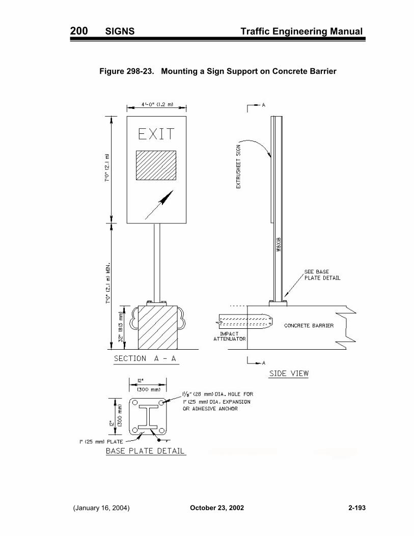
200 SIGNS Traffic Engineering Manual
October 23, 2002 (January 16, 2004) 2-193
Figure 298-23. Mounting a Sign Support on Concrete Barrier

200 SIGNS Traffic Engineering Manual
October 23, 2002 Revised January 16, 20042-194
Figure 298-24. Staking Sign Locations

200 SIGNS Traffic Engineering Manual
October 23, 2002 (January 16, 2004) 2-195
Figure 298-25. Foundation Excavations

200 SIGNS Traffic Engineering Manual
October 23, 2002 (January 16, 2004)2-196
Figure 298-26. Solid Wood Posts

200 SIGNS Traffic Engineering Manual
October 23, 2002 (January 16, 2004) 2-197
Figure 298-27. Sample Calculations for Solid Wood Posts

200 SIGNS Traffic Engineering Manual
October 23, 2002 (January 16, 2004)2-198
Intentionally blank.

300 MARKINGS Traffic Engineering Manual
October 23, 2002 Revised January 16, 2004 3-49
398 FIGURES INDEX
398-1 Two-Way Left-Turn Arrows
As noted in Section 301-9, Figure 398-1 provides design information on the spacing between the twoarrows used in marking two-way left-turn only lanes.
398-2 Standard Delineation for Median Opening for Private Access
As noted in Section 304-4, Figure 398-2 provides detail guidelines in marking a median opening forprivate drive access.
398-3 Marking a Narrow or One-Lane Bridge
As noted in Sections 202-5, 302-6, 303-2 and 304-5, Figure 398-3 provides detail guidelines markingof a narrow or one-lane bridge.
398-4 Standard Delineation for Parallel Left-Turn Lane
As noted in Sections 303-3 and 304-5, Figure 398-4 provides detail guidelines for marking a parallelleft-turn lane.
398-5 Standard Delineation for Tapered Left-Turn Lane
As noted in Sections 303-3 and 304-5, Figure 398-5 provides detail guidelines for marking a taperedleft-turn lane.
398-6 Test Line Durability
As noted in Section 350-2, Figure 398-6 illustrates the test line durability guidelines used in evaluatingperformance of pavement markings.

300 MARKINGS Traffic Engineering Manual
October 23, 2002 (January 16, 2004)3-50
Intentionally blank.

1100 HIGHWAY LIGHTING Traffic Engineering Manual
October 23, 2002Revised January 16, 2004 11-53
1. General Notes
2. General Summary of Lighting Quantities
3. Subsummaries of Quantities
4. Schematic Index
5. Plan Sheets
6. Special Details
7. Circuit Diagrams, if used
8. Tower Cross Sections, if used
1141-3.2 General Notes
General Notes should be limited to explanations required to clarify details or proposed work whichis not satisfactorily covered elsewhere in the plans, specifications, or standard drawings. Whena portion of a design varies from the standard (making it an “as per plan” item) or an “item special”is required for a unique situation, a description of the work, materials, and special instructionsshould be included in a general note to inform the contractor of what is included in the price bidfor that particular item. General Notes are also commonly used for standard bid items whichrequire supplemental information not otherwise shown in the plans or specifications, such as thesize of field offices or the method of maintaining traffic or temporary lighting. The designer shouldcontact the appropriate District or the Office of Traffic Engineering Lighting Section for currentsample notes commonly used in lighting plans.
1141-3.3 General Summary and Subsummaries
The General Summary of lighting quantities is an extension of the project General Summary andshould include the same separations for financial participation, Federal Project Numbers, andFederal Construction Code types as occur on the project General Summary. Whenever practical,bid items should be listed in standard units as described in the current publication of the ODOTItem Master. Pay item descriptions and item extension numbers should also be in accordancewith the Item Master. As in all General Summaries, a blank line should be left between groups ofno more than five pay items. Also, the sheet numbers across the top of the sheet should be thesheet numbers of each Subsummary Sheet and not the sheet numbers of the individual plansheets. Cross reference to other General Summary sheets in the plan should be included after theend of the item descriptions (e.g., “FOR ROADWAY (TRAFFIC CONTROL, STRUCTURE,RETAINING WALL) QUANTITIES, SEE SHEET XX.”).
Subsummary Sheets provide compilations of quantities for convenient portions of plans or forsimilar types of quantities, and their totals should always be carried to the lighting GeneralSummary which is used as the basis for competitive bidding on the construction contract. SeeL&D Manual Volume Three Sample Plan Sheets Figure 314-10S for a sample lightingSubsummary Sheet. Note that the quantities from each plan sheet are totaled and that thequantities carried to the lighting general summary are from the individual plan sheets (i.e., morethan one set of quantity totals may be carried to the General Summary from one SubsummarySheet).
1141-3.4 Circuit Schematic and Plan Sheet Layout
Schematic plans for circuits are required for each project. Where lighting is limited to simplediamond interchanges in rural areas, or where all circuits served by a given control center can beshown on the same sheet, the normal schematic plan may also serve as the circuit schematic

1100 HIGHWAY LIGHTING Traffic Engineering Manual
October 23, 2002 (January 16, 2004)11-54
plan, provided the delineation of circuits is clear and the schematic plan sheet is not excessivelyburdened with other details. When this is not the case, separate schematic plans for circuitsshould be prepared. The calculated voltage at each sign, at each “wye” in the circuit, and at eachterminal point should be shown on the circuit schematic plans as shown on Table 1197-8. TheControl Center Data chart (Figure 1198-11) should also be completed and shown on the circuitschematic.
If space precludes adding the Control Center Data chart and the Lighting Load listing to theschematic plan, they should be located on the first plan layout sheet. It is desirable to include aplan sheet layout on the schematic plan to more easily navigate through the lighting plan. See theL&D Manual Volume Three Sample Plan Sheets, Figure 1314-8S for a partial sampleSchematic & Sheet Layout plan sheet.
1141-3.5 Plan Sheets
Plan sheets are normally prepared at a scale of 1 inch equals 50 feet; however, plan sheets fortower lighting are usually prepared at a scale of 1 inch equals 100 feet, and lighting plans may beprepared to scales which have been approved for basic roadway plans to avoid the need ofrepeating basic layouts at different scales. See L&D Manual Volume Three Sample PlanSheets, Figure 1314-9S for a typical plan sheet. Each plan sheet should include the followinginformation:
1. Pavement and paved shoulder edges.
2. Curb lines, curb ramps and raised medians or similar channelizations.
3. Number of lane indication, either by showing lane lines or by use of lane arrows (one for eachdirectional lane).
4. Bridge structures and retaining walls, including pier and abutment locations, and length ofapproach slabs, for all bridges.
5. Structure numbers and location of each structure ground.
6. Existing and proposed overhead electrical and communication lines and underground utilitiesand culverts which affect the proposed lighting unit locations. Show width and/or boundariesof the utility right-of-way or easement and fence grounding points where overhead electricallines are involved.
7. Type, wattage or lumen rating, and ownership of existing lighting in the project area, andplanned disposition thereof.
8. Corporation lines and other quantity separation boundaries.
9. Future lighting unit locations, when applicable.
10. A north arrow, located on the upper right corner of the sheet.
11. A legend, or reference to the plan layout sheet showing the legend. The legend shall indicateby appropriate symbol the various types of light poles, light towers, pull boxes, conduits, etc.,to be installed.
12. The location of each light pole foundation, conduit crossover, pull box, control center, tower,etc., by centerline or baseline station and offset distance from the controlling pavement edge.

1200 MISCELLANEOUS Traffic Engineering Manual
October 23, 2002(January 16, 2004) 12-1
TABLE OF CONTENTSPart 12 - MISCELLANEOUS
1200 GENERAL . . . . . . . . . . . . . . . . . . . . . . . . . . . . . . . . . . . . . . . . . . . . . . 12-5
1201 TRAINING AVAILABLE . . . . . . . . . . . . . . . . . . . . . . . . . . . . . . . . . . . 12-51201-1 General . . . . . . . . . . . . . . . . . . . . . . . . . . . . . . . . . . . . . . . . . . . . . . . . . . . . . . 12-51201-2 Design of Work Zone Traffic Control Course . . . . . . . . . . . . . . . . . . . . . . . 12-51201-3 Flagging Course . . . . . . . . . . . . . . . . . . . . . . . . . . . . . . . . . . . . . . . . . . . . . . 12-51201-4 ODOT Signal Construction . . . . . . . . . . . . . . . . . . . . . . . . . . . . . . . . . . . . . . 12-61201-5 Overhead Sign Support . . . . . . . . . . . . . . . . . . . . . . . . . . . . . . . . . . . . . . . . 12-6
1202 OTHER OTE SERVICES . . . . . . . . . . . . . . . . . . . . . . . . . . . . . . . . . . 12-71202-1 Time Lapse and Video Taping . . . . . . . . . . . . . . . . . . . . . . . . . . . . . . . . . . . 12-7
1210 TRAFFIC CONTROL ZONES . . . . . . . . . . . . . . . . . . . . . . . . . . . . . . . 12-9
1211 SCHOOL ZONES . . . . . . . . . . . . . . . . . . . . . . . . . . . . . . . . . . . . . . . . 12-9
1212 SPEED ZONES . . . . . . . . . . . . . . . . . . . . . . . . . . . . . . . . . . . . . . . . . 12-111212-1 General . . . . . . . . . . . . . . . . . . . . . . . . . . . . . . . . . . . . . . . . . . . . . . . . . . . . . 12-111212-2 Procedures for Authorizing Speed Zones . . . . . . . . . . . . . . . . . . . . . . . . 12-11
1212-2.1 General . . . . . . . . . . . . . . . . . . . . . . . . . . . . . . . . . . . . . . . . . . . 12-111212-2.2 ODOT-Maintained Highways . . . . . . . . . . . . . . . . . . . . . . . . . . . 12-111212-2.3 Local Roads . . . . . . . . . . . . . . . . . . . . . . . . . . . . . . . . . . . . . . . . 12-12
1212-3 Engineering Study . . . . . . . . . . . . . . . . . . . . . . . . . . . . . . . . . . . . . . . . . . . . 12-121212-3.1 General . . . . . . . . . . . . . . . . . . . . . . . . . . . . . . . . . . . . . . . . . . . 12-121212-3.2 Speed Study Data Sheet . . . . . . . . . . . . . . . . . . . . . . . . . . . . . . 12-121212-3.3 Speed Check . . . . . . . . . . . . . . . . . . . . . . . . . . . . . . . . . . . . . . . 12-131212-3.4 Warrants for Speed Zones . . . . . . . . . . . . . . . . . . . . . . . . . . . . 12-131212-3.5 Additional Information/Considerations . . . . . . . . . . . . . . . . . . . . 12-14
1212-4 Withdrawal of Authorizations . . . . . . . . . . . . . . . . . . . . . . . . . . . . . . . . . . 12-151212-5 Documentation . . . . . . . . . . . . . . . . . . . . . . . . . . . . . . . . . . . . . . . . . . . . . . 12-15
1213 PARKING CONTROL ZONES . . . . . . . . . . . . . . . . . . . . . . . . . . . . . 12-171213-1 General . . . . . . . . . . . . . . . . . . . . . . . . . . . . . . . . . . . . . . . . . . . . . . . . . . . . . 12-171213-2 Procedure for Authorizing Parking Control Zones . . . . . . . . . . . . . . . . . 12-171213-3 Engineering Study . . . . . . . . . . . . . . . . . . . . . . . . . . . . . . . . . . . . . . . . . . . . 12-171213-4 Withdrawal of Authorization . . . . . . . . . . . . . . . . . . . . . . . . . . . . . . . . . . . 12-171213-5 Documentation . . . . . . . . . . . . . . . . . . . . . . . . . . . . . . . . . . . . . . . . . . . . . . 12-18
1214 OTHER ZONES . . . . . . . . . . . . . . . . . . . . . . . . . . . . . . . . . . . . . . . . 12-18
1215 RUMBLE STRIPS IN THE ROADWAY . . . . . . . . . . . . . . . . . . . . . . . 12-19
1220 MATERIALS AND EQUIPMENT . . . . . . . . . . . . . . . . . . . . . . . . . . . . 12-211220-1 General . . . . . . . . . . . . . . . . . . . . . . . . . . . . . . . . . . . . . . . . . . . . . . . . . . . . . 12-211220-2 New Products . . . . . . . . . . . . . . . . . . . . . . . . . . . . . . . . . . . . . . . . . . . . . . . 12-21

1200 MISCELLANEOUS Traffic Engineering Manual
October 23, 2002 (January 16, 2004)12-2
1220-3 Patented or Proprietary Materials . . . . . . . . . . . . . . . . . . . . . . . . . . . . . . . 12-211220-4 Cooperative Purchasing Program . . . . . . . . . . . . . . . . . . . . . . . . . . . . . . 12-221220-5 Alternative Purchasing Program for Local Agencies . . . . . . . . . . . . . . . 12-22
1220-5.1 General . . . . . . . . . . . . . . . . . . . . . . . . . . . . . . . . . . . . . . . . . . . 12-221220-5.2 Programming and Funding . . . . . . . . . . . . . . . . . . . . . . . . . . . 12-231220-5.3 Alternate Bids . . . . . . . . . . . . . . . . . . . . . . . . . . . . . . . . . . . . . . 12-231220-5.4 Proprietary Bids . . . . . . . . . . . . . . . . . . . . . . . . . . . . . . . . . . . . 12-231220-5.5 Prequalification of Materials . . . . . . . . . . . . . . . . . . . . . . . . . . . 12-241220-5.6 Bid Documents Package . . . . . . . . . . . . . . . . . . . . . . . . . . . . . 12-241220-5.7 Requisitions . . . . . . . . . . . . . . . . . . . . . . . . . . . . . . . . . . . . . . . 12-251220-5.8 Agreement . . . . . . . . . . . . . . . . . . . . . . . . . . . . . . . . . . . . . . . . 12-251220-5.9 Federal Approval . . . . . . . . . . . . . . . . . . . . . . . . . . . . . . . . . . . 12-251220-5.10 Pass Through of Federal Funds . . . . . . . . . . . . . . . . . . . . . . . . 12-251220-5.11 Approval and Invitation to Bid . . . . . . . . . . . . . . . . . . . . . . . . . . 12-261220-5.12 Recommendation for Award of Bids . . . . . . . . . . . . . . . . . . . . . 12-261220-5.13 Purchase Order . . . . . . . . . . . . . . . . . . . . . . . . . . . . . . . . . . . . 12-261220-5.14 Catalog Sheets, Certified Test Data and Testing . . . . . . . . . . . 12-261220-5.15 Inspection of Material Received . . . . . . . . . . . . . . . . . . . . . . . . 12-271220-5.16 Invoice Payment . . . . . . . . . . . . . . . . . . . . . . . . . . . . . . . . . . . . 12-271220-5.17 Project Completion . . . . . . . . . . . . . . . . . . . . . . . . . . . . . . . . . . 12-27
1220-6 Alternate Bids for Traffic Control and Lighting Items . . . . . . . . . . . . . . 12-271220-6.1 General . . . . . . . . . . . . . . . . . . . . . . . . . . . . . . . . . . . . . . . . . . . 12-271220-6.2 Eligibility . . . . . . . . . . . . . . . . . . . . . . . . . . . . . . . . . . . . . . . . . . 12-281220-6.3 Procedure . . . . . . . . . . . . . . . . . . . . . . . . . . . . . . . . . . . . . . . . . 12-28
1230 PLANNING / PROGRAMMING . . . . . . . . . . . . . . . . . . . . . . . . . . . . 12-311230-1 General . . . . . . . . . . . . . . . . . . . . . . . . . . . . . . . . . . . . . . . . . . . . . . . . . . . . 12-311230-2 Ball Banking Studies for Determining Curve Advisory Speeds . . . . . . 12-31
1230-2.1 General . . . . . . . . . . . . . . . . . . . . . . . . . . . . . . . . . . . . . . . . . . . 12-311230-2.2 Mounting the Ball Bank Indicator . . . . . . . . . . . . . . . . . . . . . . . 12-311230-2.3 Use of the Ball Bank Indicator . . . . . . . . . . . . . . . . . . . . . . . . . 12-311230-2.4 Recording the Safe Speed Data . . . . . . . . . . . . . . . . . . . . . . . . 12-32
1230-3 Calculation Method to Determine Curve Advisory Speed . . . . . . . . . . . 12-321230-4 Delay Studies . . . . . . . . . . . . . . . . . . . . . . . . . . . . . . . . . . . . . . . . . . . . . . . 12-331230-5 Speed Studies . . . . . . . . . . . . . . . . . . . . . . . . . . . . . . . . . . . . . . . . . . . . . . . 12-331230-6 Safety Study Guidelines . . . . . . . . . . . . . . . . . . . . . . . . . . . . . . . . . . . . . . 12-33
1230-6.1 General . . . . . . . . . . . . . . . . . . . . . . . . . . . . . . . . . . . . . . . . . . . 12-331230-6.2 Table of Contents . . . . . . . . . . . . . . . . . . . . . . . . . . . . . . . . . . . 12-331230-6.3 Title Page . . . . . . . . . . . . . . . . . . . . . . . . . . . . . . . . . . . . . . . . . 12-331230-6.4 Executive Summary . . . . . . . . . . . . . . . . . . . . . . . . . . . . . . . . . 12-33
1230-6.4.1 General . . . . . . . . . . . . . . . . . . . . . . . . . . . . . . . . . 12-331230-6.4.2 Purpose . . . . . . . . . . . . . . . . . . . . . . . . . . . . . . . . . 12-331230-6.4.3 Background . . . . . . . . . . . . . . . . . . . . . . . . . . . . . . 12-341230-6.4.4 Possible Causes . . . . . . . . . . . . . . . . . . . . . . . . . . 12-351230-6.4.5 Recommended Countermeasure and Cost . . . . . 12-35
1230-6.5 Existing Conditions . . . . . . . . . . . . . . . . . . . . . . . . . . . . . . . . . . 12-361230-6.5.1 Condition Diagram (Required) . . . . . . . . . . . . . . . 12-361230-6.5.2 Physical Condition Writeup (Optional) . . . . . . . . . 12-37
1230-6.6 Collision Diagrams . . . . . . . . . . . . . . . . . . . . . . . . . . . . . . . . . . 12-381230-6.7 Crash Data . . . . . . . . . . . . . . . . . . . . . . . . . . . . . . . . . . . . . . . . 12-381230-6.8 Crash Analysis . . . . . . . . . . . . . . . . . . . . . . . . . . . . . . . . . . . . . 12-391230-6.9 Recommendations . . . . . . . . . . . . . . . . . . . . . . . . . . . . . . . . . . 12-401230-6.10 Rate of Return . . . . . . . . . . . . . . . . . . . . . . . . . . . . . . . . . . . . . 12-411230-6.11 Photos . . . . . . . . . . . . . . . . . . . . . . . . . . . . . . . . . . . . . . . . . . . . 12-41

1200 MISCELLANEOUS Traffic Engineering Manual
October 23, 2002(January 16, 2004) 12-3
1230-6.12 Other Issues and Data . . . . . . . . . . . . . . . . . . . . . . . . . . . . . . . . 12-421230-6.13 Appendix . . . . . . . . . . . . . . . . . . . . . . . . . . . . . . . . . . . . . . . . . . 12-42
1250 CONSTRUCTION . . . . . . . . . . . . . . . . . . . . . . . . . . . . . . . . . . . . . . 12-451250-1 General . . . . . . . . . . . . . . . . . . . . . . . . . . . . . . . . . . . . . . . . . . . . . . . . . . . . . 12-451250-2 Local Government Agency / Utility Force Account Work . . . . . . . . . . . . 12-45
1250-2.1 General . . . . . . . . . . . . . . . . . . . . . . . . . . . . . . . . . . . . . . . . . . . 12-451250-2.2 Procedure . . . . . . . . . . . . . . . . . . . . . . . . . . . . . . . . . . . . . . . . . 12-45
1280 RESEARCH . . . . . . . . . . . . . . . . . . . . . . . . . . . . . . . . . . . . . . . . . . . 12-46
1295 REFERENCE RESOURCES . . . . . . . . . . . . . . . . . . . . . . . . . . . . . . 12-46
1296 FORMS INDEX . . . . . . . . . . . . . . . . . . . . . . . . . . . . . . . . . . . . . . . . . 12-47Form 1296-1. Time-Lapse & Video Request Form . . . . . . . . . . . . . . . . . . . . . . 12-49Form 1296-2. Speed Zone Warrant Sheet . . . . . . . . . . . . . . . . . . . . . . . . . . . . . 12-50Form 1296-3. Speed Study Data Sheet . . . . . . . . . . . . . . . . . . . . . . . . . . . . . . . . 12-51Form 1296-4. Sample Speed Study Data Sheet . . . . . . . . . . . . . . . . . . . . . . . . . 12-52Form 1296-5. Speed Check Form . . . . . . . . . . . . . . . . . . . . . . . . . . . . . . . . . . . . 12-53Form 1296-6. Speed Limit Revision . . . . . . . . . . . . . . . . . . . . . . . . . . . . . . . . . . 12-54Form 1296-7. Withdrawal of Issued Speed Zone Authorization . . . . . . . . . . . 12-55Form 1296-8. Field Report on Parking Practices . . . . . . . . . . . . . . . . . . . . . . . 12-56Form 1296-9. Establishment of No-Parking Restrictions . . . . . . . . . . . . . . . . . 12-58Form 1296-10. Withdrawal of Issued No-Parking Restrictions . . . . . . . . . . . . . 12-59Form 1296-11. Curve Study Form . . . . . . . . . . . . . . . . . . . . . . . . . . . . . . . . . . . . . 12-60Form 1296-12. Completed Curve Study Form . . . . . . . . . . . . . . . . . . . . . . . . . . . 12-61
1297 TABLES INDEX . . . . . . . . . . . . . . . . . . . . . . . . . . . . . . . . . . . . . . . . 12-63Table 1297-1. Symbols for Use with the Speed Study Data Sheet . . . . . . . . . 12-65Table 1297-2. Speed Zone Warrant Analysis - Highway Development . . . . . . 12-66Table 1297-3. Speed Zone Warrant Analysis - Roadway Features . . . . . . . . . 12-67Table 1297-4. Speed and Parking Zone Revision Number Assignments . . . . 12-68
1298 FIGURES INDEX . . . . . . . . . . . . . . . . . . . . . . . . . . . . . . . . . . . . . . . 12-69Figure 1298-1. Alternative Purchasing Program for Local Agencies . . . . . . . 12-71Figure 1298-2. Ball Bank Indicator . . . . . . . . . . . . . . . . . . . . . . . . . . . . . . . . . . . 12-74Figure 1298-3. Local Government Agency / Utility Force Account Work . . . . 12-75Figure 1298-4. Sample Letter Requesting Alternate Bids . . . . . . . . . . . . . . . . 12-76Figure 1298-5. Sample Letter Stating Local Decision on Alternate Bids . . . . 12-77Figure 1298-6. Sample Safety Study Table of Contents . . . . . . . . . . . . . . . . . . 12-78Figure 1298-7 Sample Safety Study Title Page . . . . . . . . . . . . . . . . . . . . . . . . 12-79Figure 1298-8. Sample Condition Diagram - Section . . . . . . . . . . . . . . . . . . . . 12-80Figure 1298-9. Sample Condition Diagram - Intersection . . . . . . . . . . . . . . . . 12-81Figure 1298-10. Collision Diagram for an Intersection . . . . . . . . . . . . . . . . . . . . 12-82Figure 1298-11. Collision Diagram for a Section . . . . . . . . . . . . . . . . . . . . . . . . . 12-83Figure 1298-12. Sample Collision Diagram . . . . . . . . . . . . . . . . . . . . . . . . . . . . . 12-84Figure 1298-13. Sample Crash Analysis . . . . . . . . . . . . . . . . . . . . . . . . . . . . . . . 12-85Figure 1298-14. Sample Rate of Return Worksheet . . . . . . . . . . . . . . . . . . . . . . 12-86Figure 1298-15. Sample Photos for a Safety Study . . . . . . . . . . . . . . . . . . . . . . 12-87Figure 1298-16. Sample Photos for a Safety Study . . . . . . . . . . . . . . . . . . . . . . 12-88

1200 MISCELLANEOUS Traffic Engineering Manual
October 23, 200212-4
Intentionally blank.

1200 MISCELLANEOUS Traffic Engineering Manual
October 23, 2002 12-5
Part 12 - MISCELLANEOUS
1200 GENERAL
This chapter serves as a repository for miscellaneous information not addressed in the other chapters.Training provided by the Office of Traffic Engineering (OTE) and other OTE services are addressed,as well as traffic control standards, policies, guidelines and procedures that involve more than one ofthe traffic control areas discussed in other TEM chapters. Traffic Control Zones are also addressed.
1201 TRAINING AVAILABLE
1201-1 General
There are various training opportunities available in the traffic engineering field (internal and external).As noted herein and on the OTE website, OTE provides courses related to various aspects of trafficcontrol design and application. Also, the Office of Quality and Organizational Developmentmaintains on their Intranet web page a catalog of courses available, including technical trainingprovided by ODOT offices.
1201-2 Design of Work Zone Traffic Control Course
The Design of Work Zone Traffic Control Course is provided to the Districts upon request, on a firstcome, first served basis, by the OTE Maintenance of Traffic Section. The course objective is to meetFederal and State standards in work zone layouts throughout the State and to improve generalknowledge about work zones.
This is a two-day course, available statewide, designed for Highway Worker 4s and CountyManagers; however, OTE also offers an abbreviated one-day course for Highway MaintenanceWorkers. Up to thirty-six employees may be trained in one class. Course topics include:
1. Traffic Control Devices and Safety Hardware.
2. Elements of Traffic Control Plans.
3. Design Workshops.
4. Layouts for Stationary and Mobile Operations.
5. Installing and Removing Traffic Control Devices.
Additional information is available on the OTE website (Table 197-3). To request training, pleasecontact Tim Michael, OTE Maintenance of Traffic Section, at 614-466-2168.
1201-3 Flagging Course
The Flagging Course is provided to the Districts upon request, on a first come, first served basis, bythe OTE Maintenance of Traffic Section. The course objective is to obtain uniformity in hand signalsthroughout the State and improve general knowledge about flagging.
This is a four hour course, available statewide, designed for Highway Maintenance Workers. Up to

1200 MISCELLANEOUS Traffic Engineering Manual
October 23, 200212-6
twenty-five employees may be trained in one class. Course topics include:
1. Attitude.
2. How to Use Flagging Equipment.
3. Proper Positioning.
4. Communication Commands.
5. Operations.
Additional information is available on the OTE website (Table 197-3). To request training, pleasecontact Tim Michael, OTE Maintenance of Traffic Section, at 614-466-2168.
1201-4 ODOT Signal Construction
The course provides training to understand the new department processes relating to signalconstruction from pre-construction activities, focusing on field inspection, and covering postconstruction review.
Length of Course: 4 HoursDesigned for: This course is designed for those who are responsible for the construction, inspectionand acceptance of traffic signals.Prerequisities: NoneCourse Size: 4 Minimum, 15 MaximumLocation: District OfficesProgram Manager: Satya Goyal, Office of Traffic EngineeringContact Number: (614) 644-6624
1201-5 Overhead Sign Support
Purpose: This course is designed to help participants develop a basic understanding of the inspectionand repair of overhead sign support.Length of Course: 4 Hours (3 hours classroom, 1 hour field)Designed For: Persons responsible for the inspection, maintenance and/or repair of overhead signsupports.Prerequisites: NoneCourse Time: VariesCourse Size: 4 Minimum, 12 MaximumLocation: District or Central OfficeProgram Manager: Office of Traffic EngineeringContact Number: (614) 752-0438 or 752-6109

1200 MISCELLANEOUS Traffic Engineering Manual
October 23, 2002(January 16, 2004) 12-7
1202 OTHER OTE SERVICES
1202-1 Time Lapse and Video Taping
The OTE Maintenance of Traffic Section provides both time lapse and real time video services tothe Districts upon request. Time permitting, these services are also available to local jurisdictions.Services available include the following:
1. Time Lapse Video for:
a. High Accident Locations.
b. Traffic Delay (Backups).
c. Signal Timing and Signal Warrants.
d. Volume Counts.
e. Liability Cases.
f. Before and After Studies.
2. Real Time Video for:
a. Training Seminars.
b. Meetings.
c. Technology Transfers.
d. New Equipment Demonstrations.
e. Haul Road Condition.
f. Detour Operation.
The Section has a video van with two high quality aerial cameras that can be raised up to a height of42 feet (12.8 meters) to obtain the best possible camera angles. The van is also equipped with threeon-board recorders (a time lapse recorder, a one-half inch variable-speed recorder and a three-quarterinch recorder).
Requests for time lapse or real-time video services should be submitted using Form 1296-1 (Time-Lapse & Video Request Form). A full-size version of the form is available on the OTE website and maybe completed and submitted by e-mail. To complete the time-lapse request form (in Adobe Acrobat):
1. Save the form (T-Lapse.pdf) to your disk or open from the web page. The form contains interactivefields which allow you to input text directly on the document.
2. Once completed, save the document.
3. Attach the file to an e-mail message and send to Mike Keller, or print the form and mail it to MikeKeller, Ohio Dept. of Transportation, Office of Traffic Engineering - 3rd Floor, P.O. Box 899,Columbus, Ohio 43216.

1200 MISCELLANEOUS Traffic Engineering Manual
October 23, 2002 (January 16, 2004)12-8
Intentionally blank.

1200 MISCELLANEOUS Traffic Engineering Manual
October 23, 2002Revised January 16, 2004 12-9
1210 TRAFFIC CONTROL ZONES
Traffic Control Zones include School Zones, Speed Zones, Parking Control Zones, Pedestrian SafetyZones, Loading Zones, No-Passing Zones and Temporary Traffic Control Zones (Work Zones).
ORC Section 4511.21 addresses the need to document the need for, and get approval of, SpeedZones and School Zone Extensions. See Section 1211 regarding School Zones and School ZoneExtensions. See Section 1212 for information regarding Speed Zones, Section 1213 for informationregarding parking controls at locations not covered by existing law (ORC Sections 4511.68 and4511.69), and Section 1214 for information on other zones.
1211 SCHOOL ZONES
OMUTCD Part 7B.11 addresses School Zones and School Zone Extensions and Section 704 of thisManual describes the procedures for processing requests for School Zone Extensions. The relatedforms are also described in Part 7 of this Manual.

1200 MISCELLANEOUS Traffic Engineering Manual
October 23, 2002 (January 16, 2004)12-10
Intentionally blank.

1200 MISCELLANEOUS Traffic Engineering Manual
October 23, 2002Revised January 16, 2004 12-11
1212 SPEED ZONES
1212-1 General
A Speed Zone is a section of street or highway where, on the basis of a geometric and trafficcharacteristic study or an engineering and traffic investigation, the prima facie speed limit set forth inORC 4511.21 (B)(1)(a) to (D) is determined to be greater or less that is reasonable or safe and theDirector and/or appropriate local authorities have declared a reasonable and safe prima facie speedlimit and erected signs in accordance with ORC 4511.21.
As noted in OMUTCD Section 2B.11, ORC Section 4511.21 establishes speed limits for all streetsand highways within the State. It also provides that the Director may alter speed limits, and that localauthorities may request that the Director determine and declare a reasonable and safe speed limit oncertain highways under their jurisdiction. Under ORC Section 4511.21 (K), a Board of TownshipTrustees may, by resolution, declare a prima-facie speed limit on unimproved highways and onhighways under their jurisdiction which are within residential and commercial subdivisions.
In altering speed limits, the minimum length of a zone not contiguous to an Speed Zone should begreater than 0.4 miles; however, extensions of existing warranted zones may be shorter.
Additional regulations on speed limits can be found in ORC Sections 4511.211 (Speed limit on privateresidential road or driveway), 4511.22 (Slow speed), 4511.23 (Speed regulations on bridges) and4511.24 (Emergency vehicles excepted from speed regulations).
Since speeds are presently only posted in English units (miles per hour), all studies related to speedlimits shall be conducted and calculated in English units. This will simplify the study process and alsoeliminate any possibility of errors in the final determined speed caused by either additional calculationsor the use of conversion factors
1212-2 Procedures for Authorizing Speed Zones
1212-2.1 General
Requests for Speed Zones are submitted through the District office using Form 1296-2 (SpeedZone Warrant Sheet). The engineering study used with this form is outlined in Section 1212-3.
1212-2.2 ODOT-Maintained Highways
All proposals for alterations of speed limits on ODOT-maintained highways shall be documentedwith the appropriate engineering study as outlined in Section 1212-3.
Once a determination has been made to alter a speed limit, the District shall forward theproposed speed limit reduction to the appropriate Ohio State Highway Patrol (OSHP) DistrictOffice for review and comment.
Following resolution of the OSHP comments, if any, the District shall prepare a description of theSpeed Zone for the Director’s approval using Form 1296-6 (Speed Limit Revision).
Following approval, the District shall erect the appropriate Speed Limit signs, record the dates onForm 1296-6, and notify the OSHP and other law enforcement agencies as appropriate.

1200 MISCELLANEOUS Traffic Engineering Manual
October 23, 2002 Revised January 16, 200412-12
1212-2.3 Local Roads
Except as provided below, all requests for alterations of speed limits on local roads (i.e.,roadsunder the jurisdiction of a highway authority other than ODOT) shall be submitted to the Districtin the form of a resolution of the local authorities. The appropriate engineering study, as outlinedin Section 1212-3, shall be included with all such requests. Concurrence from the appropriateenforcement agency should be included with the study. All requests shall be acknowledged, andthe local authorities shall be notified whether additional data will be necessary to substantiate theirrequest.
Under ORC Section 4511.21 (K), a Board of Township Trustees may, by resolution, declarea prima-facie speed limit on unimproved highways and on highways under their jurisdiction whichare within residential and commercial subdivisions.
Based on the engineering study, the District shall determine a reasonable and safe speed limit.If this determination is substantially different from that which was requested, the local authoritiesmay be asked to further substantiate their original request, and a new determination may be made.
Following resolution of any comments, the District shall prepare a description of the Speed Zonefor the Director’s approval using Form 1296-6 (Speed Limit Revision).
The District shall notify the local authorities of ODOT’s final action on the proposed Speed Zone.
If, based upon the District’s final determination, new Speed Limit signs are required, the localauthorities shall erect the signs and, upon completion of the work, forward Form 1296-6 (SpeedLimit Revision) to the District.
Upon receipt of the completed Form 1296-6 (Speed Limit Revision), the District shall notify theOSHP and other law enforcement agencies as appropriate.
1212-3 Engineering Study
1212-3.1 General
The engineering study used to support a request for alterations of speed limits should includeForm 1296-2 (Speed Zone Warrant Sheet), Form 1296-3 (Speed Study Data Sheet), Form 1296-5 (Speed Check Form). A scaled area map or sketch to identify the location of the proposed zone.
1212-3.2 Speed Study Data Sheet
The Speed Study Data Sheet (Form 1296-3) or a similar document, should be used to showphysical conditions along and adjacent to the highway, traffic control devices and accident data.Form 1296-4 is a sample of a completed Speed Study Data Sheet. The form should be preparedas follows:
1. The symbols shown in Table 1297-1 should be used in representing physical features alongthe highway.
2. Width of lanes, width of pavement, width of berm, setback of the buildings, distance to anyfixed objects within 10 feet of the pavement edge, and type and condition of the pavementsurface should also be shown.
3. On ODOT-maintained routes use SLM log points. Use a 1 inch = 0.1 mile scale along thecenterline of the roadway. Lateral dimensions need not be scaled.

1200 MISCELLANEOUS Traffic Engineering Manual
October 23, 2002(January 16, 2004) 12-13
4. Mark the beginning and end of the proposed zone, and log 500 feet beyond each end of thezone.
5. Pavement marking or restricted sight distances less than 600 feet, signals and flashers, andWarning and Regulatory Signs should be shown.
6. The number of, and point at which more than five pedestrians per hour cross or walk on thepavement should be shown.
7. Record each reported accident that occurred during the past three years by placing a symbolat the log point, and opposite the symbol, show the number of injured (I) and killed (K), orproperty damage (PD).
8. Test run date should also be recorded.
a. Test runs are to be made by driving as fast as it is comfortably safe.
b. Test runs are to be made so that other traffic will not delay the test car.
c. Record at a range of 0.10 to 0.25 mile interval or more.
d. The average speed of three test runs should be determined in each direction.
1212-3.3 Speed Check
A speed check shall be made using Form 1296-5 (Speed Check Form) or a similar form.
1. Speed checks may be taken with any device that will indicate vehicle speed with an accuracyof +10 percent.
2. Record speeds of 100 vehicles for each direction of travel (observation need not exceed onehour).
3. Speed checks should be taken at the 1/3 points (total of four checks) for zones 0.25-1.00 milein length, and at 0.5-0.75 mile intervals for zones over 1 mile in length.
1212-3.4 Warrants for Speed Zones
The data collected and the following information are used to complete Form 1296-2 (Speed ZoneWarrant Sheet).
1. Highway development consists of evaluating the extent of building development andclassification of intersections. These components are defined in Table 1297-2. Intersectionsat the end of the study area should not be counted.
The building development and intersection classification calculations are added and then thetotal is divided by the length (in miles) of the zone.
2. Roadway Features consists of evaluating the roadway design characteristics including lanewidth, shoulders curves and grades. Table 1297-3 defines the Roadway Feature components
3. 85th Percentile Speed is determined by taking spot speed observations during weekday off-peak periods. Spot speed checks should be taken to reflect only free-flowing vehicles. A

1200 MISCELLANEOUS Traffic Engineering Manual
October 23, 2002 (January 16, 2004)12-14
vehicle is considered free flow if there is a minimum of five seconds gap (headway) from theother vehicle ahead of it, and it is not accelerating or decelerating for other reasons. If it is notpossible to observe free flow conditions, then the average speed of all vehicles should beincreased 5 to 10 miles per hour to approximate the 85th percentile speed. If the 85th percentilespeed of several speed checks vary considerably and are in more than one range in thewarrant analysis, average the speed or select the most representative speed.
4. The Pace is the ten mile per hour range of speeds containing the greatest number ofobserved speeds. If the pace of several speed checks vary considerably and are in more thanone range in the warrant analysis, average the pace or select the most representative pace.
5. For Accident Experience intersection accidents not on the approach to the section understudy should not be included in the evaluation. Accidents at horizontal curves should beconsidered only after all appropriate Warning and Advisory Speed signs are in place. Cautionneeds to be exercised in applying the accident experience if there is an over representationof accidents caused by animals, the environment (such as ice), impaired driver, vehicle defect,construction, etc. It is desirable to consider a review of accidents over a three year period.
6. Test Run information is shown because the average test run speed is beneficial in supportingthe spot speed data as reflecting free flow conditions. Also it is beneficial in comparing ormatching the fit of the spot speed data to the full length of the section under study.
1212-3.5 Additional Information/Considerations
In addition to the required forms, additional data, such as photographs may be submitted. Also,there may be a need to consider adjusting the speed limit more than normal rounding to thenearest five miles per hour of the calculated speed as reflected in the speed study. Items toconsider or additional information to provide when recommending a speed limit different than thecalculated value may include:
1. A study area near or adjacent to an incorporated area or other warranted speed reduction(s).
2. Maintaining uniformity of speed limits within a contiguous section of highway.
3. Truck volumes along with the lane width should be considered, i.e., Volumes:
< 5% Low impact/consideration5% to 10% Moderate impact/consideration> 10% High impact/consideration
An effective width of 20 feet is considered adequate only for low volume roads where meetingand passing are infrequent and the truck volumes are low.
4. Land along the study area is generally fully developed based on local zoning and/or localsubdivision regulations.
5. Other conditions:
a. A large number of driveways with limited visibility.
b. The results of the test runs are not representative of the 85th percentile or calculatedspeed.
1200 MISCELLANEOUS Traffic Engineering Manual
October 23, 2002Revised January 16, 2004 12-15
c. Abnormal traffic volume flows.
d. A large number of horizontal and vertical curves requiring speed reductions.
e. The use of the road as related to access vs. mobility (e.g., functional classification).
f. Letter from local law enforcement stating that they recommend the reduction and willenforce the reduced speed limit.
g. An unincorporated area that looks to the driver the same as an incorporated area.
h. Large number of items that affects the assured clear stopping distance of the driver.
i. Volume of pedestrian traffic and/or official signed bike routes.
j. Proximity to a school.
1212-4 Withdrawal of Authorizations
The withdrawal of the authorization for a Speed Zone requires an engineering study and, insofar asis applicable, shall be accomplished in the same manner in which it was established. Form 1296-7(Withdrawal of Issued Speed Zone Authorization) is used to document the withdrawal.
1212-5 Documentation
Table 1297-4 shows the range of Revision Numbers to be used by each District for Speed Zones.These numbers shall be used on Forms 1296-6 and 1296-7.
The District shall retain the reports used in establishing the Speed Zones in their permanent files.Originals of the official document authorizing the issuance or withdrawal, as well as any originals oflocal requests or resolutions, shall also be retained permanently in District files.
A copy of the signed authorizations (Forms 1296-6 or Form 1296-7), including date of sign erectionor removal as appropriate, shall be forwarded to OTE.
For purposes of maintaining a statewide inventory and historical record, an inventory of Speed Zonesshall be maintained by OTE. Speed Zone files are available for downloading from the ODOT internalnetwork O drive at O:\Traffic\regulations. The electronic files are updated, depending on currentworkload, as revisions are received (quarterly as a minimum).

1200 MISCELLANEOUS Traffic Engineering Manual
October 23, 2002 (January 16, 2004)12-16
Intentionally blank.

1200 MISCELLANEOUS Traffic Engineering Manual
October 23, 2002Revised January 16, 2004 12-17
1213 PARKING CONTROL ZONES
1213-1 General
As noted in OMUTCD Section 2B.34, ORC Section 4511.68 establishes certain parking prohibitionsand ORC Section 4511.69 notes additional provisions related to parking locations and provisions.Special legal authority is required to establish parking controls at any type of location not coveredunder existing laws. For rural state highways, these Parking Control Zones must be authorized by theDirector. In municipalities, such authority is granted by an Ordinance passed by the Council or byother local legal authority. The adoption of a Resolution by County Commissioners or TownshipTrustees provides similar authority in rural jurisdictions.
Any regulation established in addition to those specified in ORC Section 4511.68 shall be indicatedby the use of signs.
1213-2 Procedure for Authorizing Parking Control Zones
As noted in Section 1213-1, ODOT has no responsibility for Parking Control Zones on local roads.
Requests for Parking Control Zones on ODOT-maintained highways are submitted through the Districtoffice. As noted in Section 1213-3, an engineering study is conducted to determine if a Parking ControlZone is appropriate.
Once a determination has been made to establish a Parking Control Zone, the District shall forwardthe parking control proposal to the appropriate OSHP District Office for review and comment.
Following resolution of the OSHP comments, if any, the District shall prepare a description of theParking Control Zone for the Director’s approval using Form 1296-9 (Establishment of No-ParkingRestrictions).
Following approval, the District shall erect the appropriate Parking Control signs, record the dates onForm 1296-9, and notify the OSHP and other law enforcement agencies as appropriate.
1213-3 Engineering Study
Section 1213 (Parking Control Zones) should be reviewed prior to submitting the study. Theengineering study used to support a request for a Parking Control Zone shall include a field surveyconducted to acquire necessary data to complete Form 1296-8 (Field Report on Parking Practices).It should also include a sketch of the location and/or photographs to document the physical conditionsnoted in the survey report.
1213-4 Withdrawal of Authorization
The withdrawal of the authorization for a Parking Control Zone requires an engineering study and,insofar as is applicable, shall be accomplished in the same manner in which it was established. Form1296-10 (Withdrawal of Issued No-Parking Restrictions) is used to document the withdrawal.

1200 MISCELLANEOUS Traffic Engineering Manual
October 23, 2002 Revised January 16, 200412-18
1213-5 Documentation
Table 1297-4 establishes Revision Numbers to be used by each District for Parking Control Zones.These numbers shall be used on Forms 1296-9 and 1296-10.
The District shall retain the reports used in establishing the Parking Zone in their permanent files.Originals of the official document authorizing the regulation shall also be retained permanently inDistrict files.
A copy of the signed authorizations, including date of sign erection, shall be forwarded to the Officeof Traffic Engineering (OTE).
For purposes of maintaining a statewide inventory and historical record, an inventory of Parking Zonesshall be maintained by OTE. No Passing Zone files are available for downloading from the ODOTinternal network O drive at O:\Traffic\regulations. The electronic files are updated, depending oncurrent workload, as revisions are received (quarterly as a minimum).
1214 OTHER ZONES
As noted in Section 1210, Traffic Control Zones also include Pedestrian Safety Zones, Loading Zones,No-Passing Zones and Temporary Traffic Control Zones (Work Zones). No-Passing Zones areaddressed in OMUTCD Part 3. Temporary Traffic Control Zones are addressed in OMUTCD Part 6and in Part 6 of the TEM.

1200 MISCELLANEOUS Traffic Engineering Manual
October 23, 2002Revised January 16, 2004 12-19
1215 RUMBLE STRIPS IN THE ROADWAY
Rumble strips are composed of a pattern of grooves or depressions made in the roadway or shoulderof the highway to produce an audible and/or vibratory warning to drivers. They are not, by themselves,considered traffic control devices (they are “geometric features of the roadway”). Rumble strips withinthe roadway (traveled lane) are addressed in this section.
Policy No. 322-001(P), Policy on the Use of Rumble Strips on Shoulders addresses details andprocedures for the use of rumble strips on the shoulders of ODOT-maintained highways. L&D ManualVolume One Section 605, SCD BP-9-1 and CMS Item 618 address ODOT standards andspecifications related to the use of shoulder rumble strips. For questions on shoulder rumble strips,contact the Office of Roadway Engineering Services.
Rumble strips have been shown to be effective in certain circumstances in slowing and/or alertingdrivers for various applications. However, installation of rumble strips should only be considered whenall other appropriate standard traffic control devices have failed to resolve the traffic problemsatisfactorily.
The use of rumble strips at locations in the roadway shall be at the discretion of the District DeputyDirector. This decision should be based on a review and recommendation by the District SafetyReview Team. Applications for consideration of rumble strips include the following:
1. Rural stop approaches with high accident rates.
2. Signalized intersections with high accident rates.
3. Exit ramp deceleration lanes.
4. Gore areas.
5. Narrow and one-lane bridges.
6. Locations with abrupt changes in horizontal alignment.
7. Intersections with inadequate stopping sight distance caused by vertical or horizontal alignment.
8. Transitional areas from “high-type” facilities to “low-type.”
9. Construction areas, e.g., median crossovers.
10. Approaches to toll booths.
11. Railroad crossings with sight distance restrictions and accident potential.
Design information is available upon request from the OTE Standards Section; however, detaildesigns are not currently available for each of the applications noted.
When rumble strips are installed, a RUMBLE STRIPS sign (W8-H15) should be used. This sign isshown in the Standard Sign Design Manual (Section 295-2)

1200 MISCELLANEOUS Traffic Engineering Manual
October 23, 2002 (January 16, 2004)12-20
Intentionally blank.

1200 MISCELLANEOUS Traffic Engineering Manual
October 23, 2002Revised January 16, 2004 12-21
1220 MATERIALS AND EQUIPMENT
1220-1 General
This section includes information about various procedures developed to address the review andapproval of new products and the purchase of traffic control related materials and equipment.
1220-2 New Products
Information regarding the ODOT new products program will be incorporated into this section.
1220-3 Patented or Proprietary Materials
Patented or proprietary materials, specifications, or processes shall not be included in a contractunless one of the following conditions applies:
1. The item is to be purchased or obtained through competitive bidding with equally suitable items.In which case, the plans shall specify a minimum of two acceptable items and include the phrase“or approved equal.”
2. No equally suitable alternate exists.
3. The item is essential for compatibility or synchronization with, or maintenance of, existing facilitiesor equipment.
4. The item is used for research, or for a distinctive type of construction, on relatively short sectionsof a facility for experimental purposes.
5. There is a determination by the District Deputy Director (DDD) that it is in the best public interestto specify one such item, to the exclusion of any other acceptable alternate.
Where a single item is specified, as in conditions 2 through 5, a request and justification shall besubmitted to the appropriate District. The District shall evaluate the request; coordinate with the DDD,and when the situation described in condition 5 applies, coordinate with FHWA if appropriate; andsubsequently notify the requesting agency of the disposition of the request.
Where research or experimentation is proposed, it will also be necessary to set up an evaluationprogram.
In the case of traffic signals, the vast majority of alternate bid requests are made for controllers oremergency vehicle preemption. Districts should consider the use of proprietary bids instead ofalternate bids when:
1. The signal controllers are an extension of an existing arterial coordinated signal system. Typicallythe number of controllers being added is less than the number of existing controllers in the system.The coordinated arterial may be controlled by either on-street masters, directly by a central controlcenter or simple hardwire with time based control. There should be no upgrading of the existingcontrollers, or the upgraded existing controllers will be evaluated as new/added controllers.
2. At least 50% of the agency’s controllers are of a single brand. This is in recognition of thesignificant investment made by the maintaining agency. There should be no upgrading of theexisting controllers, or the upgraded existing controllers will be evaluated as new/addedcontrollers.

1200 MISCELLANEOUS Traffic Engineering Manual
October 23, 2002 Revised January 16, 200412-22
Preemption equipment and video detection may also be considered if 50% of the agency’ssignalized intersections operate with a single brand of equipment. The extension of preemptionequipment on an existing preempted arterial will not be a basis for approval of proprietary bids forpreemption equipment.
3. If at least 50% of the agency’s equipment is comprised of two brands, consideration may be givento limiting the bids to the two brands without the use of the phrase “or approved equal”.
4. If at least 50% of the agency’s controllers are of a single brand, central control software upgradesmay be considered. The single brand controllers do not have to be currently connected to thecentral control. Upgraded existing controllers will be evaluated as new/added controllers. Theaddition of an interconnection card to an existing controller is not considered an upgrade to thecontroller.
5. Aesthetically designed signal supports may be considered if at least 50% of the agency’s signalizedintersections utilize the supports. Extension of an arterial with existing aesthetically designed signalsupports will not be a basis for approval of proprietary bids.
Proprietary bids for aesthetically designed highway lighting supports should not be consideredbecause of the numerous manufacturers of similar support designs.
In lieu of proprietary bids for aesthetically designed signal or lighting supports, alternate bids maybe taken using three brands of similar aesthetically designed supports for the generic bid and analternate bid for the preferred choice. If three brands of similarly designed signal supports are notutilized, the generic bid will typically be for a standard painted TC-81.20 mast arm support.
For the occasional proprietary bid request that does not comprise the most common project workitems, the District may submit the request to an ad hoc committee for review. The committee will becomposed of representatives from ODOT Central Office, Districts, and the FHWA.
When determining if a proprietary bid is justified, the District should make every possible effort todetermine that an alternate bid will not suffice instead of a proprietary bid. When a District determinesthat a proprietary bid is justified, written documentation must be kept on file supporting the use ofproprietary items.
Should the request not be approved, the District must inform the requesting agency they may consideralternate bidding procedures, and that Federal-aid participation will be based on the lowest price soestablished.
1220-4 Cooperative Purchasing Program
Under the Cooperative Purchasing Program, political subdivisions may purchase machinery, materials,supplies and other articles from the ODOT Annual Term Contracts and the ODOT Single PurchaseContracts with their own funds. A copy of the program may be obtained from the Office of Contracts,Purchasing Services (Table 197-3).
1220-5 Alternative Purchasing Program for Local Agencies
1220-5.1 General
ODOT also sponsors another program with respect to the purchase of traffic control materials forinstallation and use by local government agencies. In this program, funding for the purchase oftraffic control materials for installation and use by a requesting local governmental agency isallocated by ODOT to the local governmental agency and does not involve the use of ODOT term

1200 MISCELLANEOUS Traffic Engineering Manual
October 23, 2002Revised January 16, 2004 12-23
purchase contracts. This method was developed primarily for traffic control materials, but canencompass the purchase of other roadway appurtenances such as roadway lighting, signing andstreet beautification items.
This purchase order procedure was originally created to provide local agencies with a means ofpurchasing traffic signal materials with Federal project funds. The procedure has also been usedto purchase signing materials and can be expanded to include other roadway appurtenances. Allmaterials acquired using this procedure are to be installed by the local agency without cost toODOT.
If traffic signal material is involved, data must be submitted for evaluation of traffic signal warrantsas contained in OMUTCD Part 4. The signal warrant data shall be evaluated and approved by theDistrict. Assistance is available from OTE upon request. Only the intersections with Districtapproved signal warrants are eligible for federal funding of traffic signal materials.
The following procedure has been the process to be followed in procuring materials andequipment for purchase order contracts. These functions are also shown as a flow chart in Figure1298-1. The steps shown in Sections 1220-5.7 through 1220-5.10 are initiated concurrently.
1220-5.2 Programming and Funding
The District shall prepare and submit the programming package to the Office of SystemsAnalysis Planning. Any State or Federal funds allocated to the agency that are eligible may beutilized, except for nontraditional transportation funds. Funds shall be sufficient to encompass thematerial costs, plus preliminary and construction engineering if requested. Any additional cost inthe procurement of materials due to increased costs, or to insure a completed installation, shallbe the agency’s responsibility unless changes are approved in advance and funds are available.
The agency’s cost participation, the local share, whether due to normal project funding splits or100 percent local cost items, shall be based on the estimate as provided by the agency in Section1220-5.6(2a).
1220-5.3 Alternate Bids
Alternate bids cannot be used in the automated purchase order system. There must be only onebid item for each item.
1220-5.4 Proprietary Bids (also see Section 1220-3)
The purchasing regulations allow a vendor to supply a comparable item for any proprietary brandlisted in the bid package. There are two ways to purchase approved proprietary items:
1. Appear before the State Controlling Board and request an exemption from the Departmentof Administrative Services purchasing regulations.
2. Have the agency use their own purchasing system to purchase the approved proprietaryitems. The Department utilizes a “Pass Through of Federal Funds” account in the Office ofAccounting so that the agency does not have to use their own funds in the purchase. Theagency submits the invoices from the vendors to the District for payment. This processrequires that all preliminary engineering documents and approvals be processed as if theDepartment were the sole purchasing agent.

1200 MISCELLANEOUS Traffic Engineering Manual
October 23, 2002 (January 16, 2004)12-24
1220-5.5 Prequalification of Materials
The agency can prequalify a number of manufacturers of a purchase order item. A minimum ofthree brands should be listed and the supplied item must be one of these specified brands. Theagency must document the procedure or reasons for limiting bidding.
1220-5.6 Bid Documents Package
The agency shall prepare the bid documents package and submit it to the District. The Districtshall coordinate and consolidate review comments and respond to the agency. The bid documentspackage shall include the following information as required:
1. Preliminary Plans or Sketches.
a. For traffic signal projects, plans or sketches should depict existing and proposed signaloperation and equipment locations. The complexity of the detail drawings will bedetermined by the District based on the extent of the signal work involved.
b. If the work is not signal related, the drawings shall show the locations of all proposeditems and any existing conditions that will be affected. Roadway lighting work may requirean illumination review to determine the effect the proposed lighting will have on theroadway. Based on the scope of the roadway lighting, the District will determine if thisreview is necessary.
c. Plans and sketches shall show right-of-way.
2. Summary of Estimated Quantities and Cost Estimate.
a. Detailed sub-summaries with item descriptions and quantities shall be prepared. Theyshall be subdivided by each intersection and separately subtotaled for any funding splits.
b. Two general summaries shall also be submitted; one with the cost estimate included forODOT’s use and the other without the cost estimate. The general summary without thecost estimate is used in the bid package that will be sent to the vendors and will provideplaces for the bid prices to be stated by the vendors.
c. Usually, the project must be separated into multiple bid packages in order to group similaritems so that the various vendors can bid on only the item group that they can supply.
3. Material Specifications.
a. ODOT’s Construction and Material Specifications (CMS) and SupplementalSpecifications shall be used where feasible, but may be supplemented by the agency’srequirements, as necessary.
b. ODOT does not review and approve shop drawings or catalog sheets. If the agency wantsto review and approve these items, this requirement must be included in the materialspecifications.
4. Miscellaneous Documentation.
a. Assurance that all pavement markings, signing and signal installations within the projectarea are, or will be, in compliance with the OMUTCD. This should be accomplished by afield inspection by District and agency personnel, with any deficiencies documented.

1200 MISCELLANEOUS Traffic Engineering Manual
October 23, 2002Revised January 16, 2004 12-25
The deficiencies shall be corrected by the agency prior to completion of their installationof the purchased materials. By performing this inspection early in the project development,materials can be included in the bid package to correct the deficiencies.
b. Assurance that all work is within the right-of-way.
c. A proposal for disposition of removed equipment.
d. Justification of any proprietary items or necessary documentation for computer controlledsignal systems, signal preemption devices and other specialized equipment.
e. A schedule of the agency’s installation work, based on equipment delivery dates. Thisshould also be referenced in the agreement.
f. Maintenance of Traffic standards which will govern the agency’s work.
All plans and documents in the bid document package shall be on 8 ½ x 11 inch (21.6 by 28millimeter) sheets, and the agency shall submit all computerized plans and document files to theDistrict on 3.5 inch computer disks or by electronic file transfer.
After the agency provides the District with the final, District approved, version of the biddocuments package, the district will provide OTE with the originals of the bid documents package.
1220-5.7 Requisitions
The District or the Office of Accounting will enter the project into the automated purchasingsystem. The OTE Administrator shall be added as a required authorization on the requisition.
1220-5.8 Agreement
OTE will send to the District an agreement to be forwarded to the agency for signature.
The agreement will be reviewed by the agency, signed by the agency's contractual officer, andreturned to the District for the Deputy Director to sign.
The District will keep the original of the executed agreement and provide copies to the agencyand OTE.
If the agency is responsible for a share of the project costs:
1. A check shall accompany the agreement when returned to the District.
2. The District shall forward the check to the Office of Payroll and Project Accounting andthat office will ensure that the agency's check is properly credited to the project andprocessed. The District will furnish OTE with a copy of the check transmittal letter.
1220-5.9 Federal Approval
If Federal funding is involved, OTE will submit a bid document package, excluding the agreement,to the Office of Payroll and Project Accounting to obtain PS&E approval from FHWA.
1220-5.10 Pass Through of Federal Funds
If a “Pass Through of Federal Funds” process is used as described in Section 1220-5.4:

1200 MISCELLANEOUS Traffic Engineering Manual
October 23, 2002 (January 16, 2004)12-26
OTE will request that the Office of Accounting establish the account and create the requisitionfor the agency's items. The Office of Accounting shall add the OTE Administrator as a requiredauthorization on the requisition.
1220-5.11 Approval and Invitation to Bid
When all of the concurrently initiated actions in Sections 1220-5.7 through 5.10 are finalized,OTE will:
1. Approve the electronic requisitions so they proceed to Purchasing Services;
2. Forward the bid documents package to Purchasing Services to process an Invitation to Bid;and
3. Advise the agency to proceed with their purchase process if a “Pass Through of FederalFunds” process is used (see Section 1220-5.4).
1220-5.12 Recommendation for Award of Bids
After the bids have been received and reviewed by the Purchasing Services, they will betabulated and sent to OTE. OTE shall process the bids as follows:
1. Discuss the bids with the District and the agency and make award recommendations.
2. In the case of Federal projects with active Federal oversight, obtain FHWA’s concurrence withthe award recommendations.
3. Forward award recommendations to Purchasing Services for further processing.
1220-5.13 Purchase Order
Purchasing Services will create the purchase orders to be issued to the supplier. The purchaseorder shall include:
1. A “Shop Drawing” note indicating that material catalog sheets or data sheets shall besubmitted to the agency before any material is shipped; and
2. A note that all invoices are to be mailed directly to the District and materials shipped to theagency.
For those items requiring certified test data as determined by the District, the Puchase Order shallalso indicate that submissions are required to be submitted to the District by the supplier. Thiswould include any submissions which contain material composition analysis which must be inaccordance with a recognized standard.
1220-5.14 Catalog Sheets, Certified Test Data and Testing
If specified in the project specifications, catalog sheets shall be received and reviewed by theagency. The agency will indicate comments on the catalog sheets as to the acceptability of thesubmitted items and their compliance with the material specifications. The submittal shall bemarked “Approved,” “Approved as Noted,” or “Not Approved,” and will be transmitted to the variousaffected parties.
The agency shall notify the material supplier as to the acceptability of the submitted product, thus

1200 MISCELLANEOUS Traffic Engineering Manual
October 23, 2002(January 16, 2004) 12-27
enabling them to commence fabrication and/or shipping in the case of an approval, or to makeother arrangements in the case of disapproval. The supplier will be advised to send invoices to theDistrict.
Certified test data shall be received by the agency with material shipment. It shall be sent to theDistrict for review and retention.
Submittals requiring testing shall be conveyed to the District Highway ManagementAdministrator and the Office of Materials Management for review and approval.
1220-5.15 Inspection of Material Received
Upon receipt of materials, the agency shall contact the District to arrange for the inspection of thematerials and completion of the necessary Receiving Forms (MR-541) and Field InspectionReport (TE-30) if required. If only Receiving Forms (MR-541) are necessary, the District maydirect the agency to fulfill this function.
1220-5.16 Invoice Payment
The following shall be submitted to the District for payment: invoice, Invoice Coding Strip (AU-60), Receiving Form (MR-541), Field Inspection Report (TE-30) if required, and Certified testdata if required.
1220-5.17 Project Completion
Upon project completion, the agency shall contact the District to arrange a final field inspection.If Federal funding was used and the project has direct Federal oversight, FHWA shall be includedin the process and its representative should be given copies of all approved certified test datasubmittals.
After completion of the inspection and correction of any deficiencies, the District will documentthat ODOT accepts the physical work as performed by the agency. The District will also documentthat any deficiencies identified in the engineering phase of project development have beencorrected.
The District shall formally advise the Office of Payroll and Project Accounting when the projectis completed and acceptable to ODOT and FHWA. With this information the Office of Payrolland Project Accounting will seek final Federal reimbursement of project funds. This process willfinalize the project.
1220-6 Alternate Bids for Traffic Control and Lighting Items
1220-6.1 General
The alternate bid procedure has been established to permit a local agency to obtain a specificbrand, feature or design of traffic control or lighting device for use on a project.
Some of the generalized uses of the procedure are as follows:
1. To obtain a specific brand and model of equipment, which is expected to simplify maintenanceand operation or reduce operating costs.
2. To obtain supports which include architectural features or designs used exclusively within thejurisdiction of the local agency, and which are more expensive than the support designs

1200 MISCELLANEOUS Traffic Engineering Manual
October 23, 2002 (January 16, 2004)12-28
normally used in ODOT plans. This may include items in local areas with historic or themebackgrounds.
3. To obtain a specialized design feature which is patented or manufactured by only one supplier,and which the agency expects will improve maintenance or operation.
4. To obtain devices which are not presently justified for efficient use on the project or are notacceptably justified by agreed future conditions but which the local agency believes will benecessary at some future time.
5. To obtain items whose extra costs are not justified when lower cost items can provideacceptable results.
1220-6.2 Eligibility
As early as practical during the design stage, the local agency should inquire from the DistrictProduction Administrator as to whether or not an item is eligible for normal project participation.In many cases where a precedent has not been established, the request is considered with FHWA(when Federal funds are involved) and a decision is rendered. This request may be madeinformally or in writing depending on the nature of items involved and precedents alreadyestablished. If it is determined that alternate bids are necessary, the local agency shall submit arequest in writing through the appropriate District that alternate bids be taken. Figure 1298-4shows a sample letter which may be used by local authorities to request alternate bids.
Each request must include the following information:
1. Specific brand (and model) or design features desired.
2. Reasons why the local agency desires the product or feature in question.
3. Locations for use on the project under consideration.
4. Past history or experience with the product where applicable.
5. Confirmation that the local agency understands the procedures of the alternate bid process(Section 1220-6.3).
6. Name and telephone number of the responsible authority within the local agency to becontacted after the bid opening to determine the disposition of the alternate bids.
1220-6.3 Procedure
The alternate bid procedure consists of adding a second bid item (alternate bid) for each general(generic) bid item which is affected by the local agency's special requirements. The generic biditem reflects the customary item that is sufficient to meet the needs of the project and is eligiblefor normal project participation. The alternate bid item describes a similar item that will satisfy thesame needs of the project but also contains the local agency's special requirements. After bidopening, ODOT compares the costs of generic versus alternate bids for the affected bid items. Inthe event the generic items are bid at a higher price than the alternate items by the successfulbidder, the award will normally be made on the basis of the alternate items with no additional costincurred by the local agency. In the event the alternate items are bid at a higher price than thegeneric items, the maintaining agency will have the opportunity to either reject the alternate bidsor to agree to accept the alternate bids with the understanding that local agency funds will pay theentire cost differential between the alternate bid and the generic bid.

1200 MISCELLANEOUS Traffic Engineering Manual
October 23, 2002(January 16, 2004) 12-29
A representative of the District will contact the responsible authority of the maintaining agency(see Section 1220-6.2 item number 6) by telephone and furnish unit prices and total bids for thegeneric and alternate bid items involved, including cost differentials for the apparent low bidder.Where the alternate bid process involves more than one item description, alternate bids can beselectively accepted or rejected; however, similar equipment types should be grouped together,such as all controller bid items or all preemption bid items. Only a limited period of time (one ortwo days) will be available for the maintaining agency to make known their preference by returntelephone call (if time is needed to deliberate the preference) and to forward a letter with writtenconfirmation to the District.
The apparent low bidder for the project will be determined solely on the generic bid pricessubmitted (not the alternate bid prices). The cost differential presented to the local agency will bebased only upon generic and alternate bid prices submitted by the apparent low bidder. Alternatebid prices submitted by other bidders will not be considered when determining the local agency'sadded costs.
The project must be awarded or rejected within ten days of the bid opening; therefore, ODOT mustreceive the local agency's written acceptance of the alternate bids within the time period or ODOTmay award the project on the basis of the lowest bids. If the local agency refuses the alternatebids, written confirmation is still required for ODOT documentation. The letter of confirmation mustbe sent directly to the District Production Administrator. The letter shall also include astatement of willingness of the maintaining agency to pay the entire difference in cost, if the localchoice is alternate bids involving a higher cost than that for generic bid items. The letter shall besigned by the contractual officer for the local agency. Figure 1298-5 shows a sample letter thatmay be used by local authorities to acknowledge acceptance or rejection of the alternate bids.

1200 MISCELLANEOUS Traffic Engineering Manual
October 23, 2002 (January 16, 2004)12-30
Intentionally blank.

1200 MISCELLANEOUS Traffic Engineering Manual
October 23, 2002Revised January 16, 2004 12-31
1230 PLANNING / PROGRAMMING
1230-1 General
This section is intended to address miscellaneous planning issues, including various traffic engineeringsafety studies.
1230-2 Ball Banking Studies for Determining Curve Advisory Speeds
1230-2.1 General
The Ball Bank Indicator is an instrument used to determine the recommended maximum speedto display on an Advisory Speed plate when the plate is used to supplement a curve (or turn)Warning Sign. This recommended maximum speed is considered to be the maximum safe speedthat a passenger car can comfortably traverse the curved section of roadway.
This instrument consists of a steel ball in a scaled curved glass tube filled with an alcohol solution.The tube, bent on the arc of a circle, is graduated from 0 to 20 degrees both to the left and rightof the zero point. The tube is enclosed in a metal case (see Figure 1298-2).
Safe speeds on horizontal curves must also be related to the safe-stopping sight distance andvarious other factors which cannot be determined by using either the Ball Bank Indicator or thecalculation method for determining curve advisory speed signing (Section 1230-3).
Since speeds are presently only posted in English units (miles per hour), all studies related toadvisory speeds shall be conducted and calculated in English units. This method will simplify thestudy process and also eliminate any possibility of errors in the final determined speed caused byeither additional calculations or the use of conversion factors.
1230-2.2 Mounting the Ball Bank Indicator
When mounting the Ball Bank Indicator, the car should be in a stationary level position. Thespeedometer of the automobile must be accurately calibrated and the tires uniformly inflated. Theindicator should be mounted as near as possible on a vertical surface, with the steel ball at thezero point. All occupants who are to be in the car when the observations are to be made shouldbe in the same position when mounting or checking the instrument as when making the test.
This is necessary because changing position of the passenger or the load in the car may causethe car body to tilt to the right or left depending on the transfer of the load from one side to theother and this tilting action or body roll is reflected in a change in the ball bank readings.
1230-2.3 Use of the Ball Bank Indicator
The use of the Ball Bank Indicator to measure the safe speed on curves involves the efforts of twopersons - one to drive and the other to observe the indicator. The following directions should beobserved in each test made:
The driver should:
1. Appraise the curve under observation to determine the approximate safe speed that may bemaintained throughout the curve.
2. Conduct the first test at a speed 10 miles per hour below the appraised speed.

1200 MISCELLANEOUS Traffic Engineering Manual
October 23, 2002 (January 16, 2004)12-32
3. Make each succeeding test at a speed 5 miles per hour greater than the last one until the BallBank Indicator has reached 10, 12 or 14 degrees as specified in Section 1230-2.4.
4. Attain the trial run speed on each test at a distance of at least one-quarter mile from thebeginning of the curve.
5. Maintain a course throughout the curve precisely in the center of the lane and at uniformspeed.
The observer carefully notes the position of the ball at the approximate center of the curve andrecords the reading. The reading shall be recorded as right or left of zero.
1230-2.4 Recording the Safe Speed Data
It is important that all information be recorded that is indicated on the heading of the Curve StudySheet (Form 1296-11). A full size Curve Study Sheet is available from the OTE website.
As provided for on the Curve Study Sheet, trial runs should be made in each direction. For thespecified speed ranges, the following ball bank angles shall be used:
Below 20 miles per hour - 14 degrees 20 to 30 miles per hour - 12 degrees 30 to 40 miles per hour - 10 degrees
1230-3 Calculation Method to Determine Curve Advisory Speed
If trial run information is not available, the advisory speed indications for horizontal curves may becalculated by inserting the curve data into the following equation relating superelevation, pavementfriction, radius of curvature and vehicle speed:
Vmph e f R� � �( ) .0 067
Where V = speed of vehicle in miles per houre = superelevation in feet per foot of horizontal widthf = transverse coefficient of frictionR = radius of curvature in feet.
Recommended Values of Transverse Coefficient of Friction:
Operating Speed Transverse Coefficient of Friction
30 mph 0.16
40 mph 0.15
50 mph 0.14
60 mph 0.13
Safe speeds on horizontal curves must also be related to the safe-stopping sight distance and variousother factors which cannot be determined by using either the Ball Bank Indicator (Section 1230-2) orthis calculation method.

1200 MISCELLANEOUS Traffic Engineering Manual
October 23, 2002(January 16, 2004) 12-33
1230-4 Delay Studies
This section is reserved to address information available regarding delay studies. In the interim,contact OTE for such information if needed.
1230-5 Speed Studies
See information in Section 1212-3 regarding the Speed Check and Test Runs used to evaluateproposed changes in speed limits.
1230-6 Safety Study Guidelines
1230-6.1 General
The following safety study guidelines are for use by ODOT personnel, consultants and localjurisdictions conducting safety engineering studies and preparing reports. The safety engineeringstudy is an analysis of roadway and traffic related data to determine the possible cause of anidentified crash pattern at an intersection or highway section. The safety engineering study alsoprovides alternative countermeasure(s) meant to mitigate the crash pattern(s).
By establishing a uniform format for ODOT safety engineering studies and providing direction forcompleting safety engineering reports, these guidelines are intended to assure the completenessof a study and to expedite review and analysis of the reports. The following section outline thecomponent parts of a safety study and the related report.
1230-6.2 Table of Contents
All safety study reports shall have a Table of Contents (see Figure 1298-6).
1230-6.3 Title Page
The title page of a safety study report should show the District, county, route, section, High CrashLocation Identification System (HCLIS) Number (#), the year of the Safety Annual Work Program(SAWP), study completion date and a location map (see Figure 1298-7).
1230-6.4 Executive Summary
1230-6.4.1 General
Every safety engineering study report shall include an Executive Summary, which can be usedas an overall summary of the report. The following sections outline the information that shouldbe included in this Summary.
1230-6.4.2 Purpose
This part of the Executive Summary is used to identify the location being studied and give thereasons for conducting the safety engineering study.
Example 1
The intersection of U.S. 250 & Kidron Road has been selected for analysis and study basedupon a ranking of #305 in the 2001 HCLIS for the safety program. The purpose of the studyis to determine safety issues at the intersection, establish priorities based upon rate of return,and develop improvements to enhance safety at this location.

1200 MISCELLANEOUS Traffic Engineering Manual
October 23, 2002 (January 16, 2004)12-34
Example 2
This section of road appears on District 5's 1999 listing of high crash locations, it is rated #348in the state. The purpose of this report is to study this location and analyze the crashes todetermine what if any actions can be taken to reduce these crashes.
1230-6.4.3 Background
This section of the Executive Summary is used to identify the location being studied, type offacility, type of traffic control, history of problems or crashes and reason for the study.
Example 1
This section of U.S. 20 is between the intersection of S.R. 58 and the four-lane section, whichbegins approximately 1 mile west of the interchange with S.R. 511. This portion of U.S. 20 isfairly straight and flat and it is marked with a single dashed center line except at theintersection of S.R. 58 where there is an exclusive left-turn lane on U.S. 20.
The section between SLM 6.60 and SLM 7.10 appears on the 1997 HCLIS as location #261and on the District’s 1998-99 AWP as location #33. However, a longer section was studieddue to complaints received regarding the transition from the four-lane section to the two-lanesection.
The complaints were received after two fatal crashes (one in 6/98 and one in 7/98) in whichthe U.S. 20 westbound vehicle traveled left of center and struck an eastbound vehicle headon. However, it does not appear as though the westbound drivers were confused by thetransition, nor did it appear that they thought they were still on the four-lane section of highway.According to witness statements, there were no other westbound vehicles in the vicinity or anyobjects in the roadway. Therefore, they were not attempting to pass another vehicle or swerveto avoid an object. Both westbound drivers gradually crossed over the center line striking theeastbound vehicles.
Example 2
This approximately 1.16 mile section of S.R. 56 is located in Pickaway County. It is part of therural state highway system under the jurisdiction of District 6 of the Ohio Department ofTransportation (ODOT). The section under study, log point 26.44 to 27.60, begins at theintersection of S.R. 159 and S.R. 56 and extends in an easterly direction just beyond andincluding the Township Road (T.R.) 62 and S.R. 56 intersection. The project limits extendlongitudinally 1000 feet along the center line at intersections and 200 feet laterally from thecenter line along the entire length of the study area. Based on information supplied by District6, PIC-56-26.92 to 27.41 was ranked #135 on the 1997 HCLIS and #290 on the Department’s1998 HCLIS.
Example 3
This segment is located in central Knox county in Morris Township. It begins 1.20 miles northof the City of Mt. Vernon. It ends 3.50 miles south of the Village of Fredricktown. This sectionof S.R. 13 is curved and on a steep grade while crossing the CSX railway. S.R. 13 is generallystraight and level north and south of this section. The CSX railroad crossing is at the 13.38mile marker.

1200 MISCELLANEOUS Traffic Engineering Manual
October 23, 2002(January 16, 2004) 12-35
Example 4
U.S. 250 is a two-lane rural principal arterial that runs east and west and Kidron Road is a two-lane rural minor collector that runs north and south.
The intersection of U.S. 250 and Kidron Road (C.R. 52) is currently #305 statewide on the1999 HCLIS, and #29 on the District 3 2000-2001 SAWP. This location was previously studiedin January 2000 as #233 on the 1998 HCLIS, and in May 1997 as #177 on the 1995 HCLIS.
As a result of the January 2000 study, the following improvements were made: the unpavedisland on the other approach of Kidron Road was paved, and the STOP sign which was in theisland was removed and placed on the left side of Kidorn Road to create a dual installation.Also, both the north and south approaches were improved (grades leveled) to optimize sightdistance. These improvements were completed approximately July of 1998.
1230-6.4.4 Possible Causes
The possible causes or deficiencies in the roadway location are identified in this section of thereport through detailed analysis of crash patterns, roadway conditions, existing traffic control,traffic volumes, vehicle speeds, etc.
Example
The safety problems identified at this location are as follows:
� The sight distance for the south approach of Line Rd. is obstructed.
� There are an insufficient number of gaps for Line Rd. traffic to pull onto U.S. 36.
� There are no exclusive turn lanes to separate left turns from the rest of the traffic stream.
� The radii at the intersection are not large enough to allow heavy vehicles to turn easily.
1230-6.4.5 Recommended Countermeasure and Cost
Recommended countermeasures and their related costs are also noted in the ExecutiveSummary. A recommended countermeasure is a highway safety treatment or correctiveactivity designed to alleviate a safety problem or a potentially hazardous location. The cost ofevery countermeasure is the cost of improvement through force account or contract work andshould be included with every countermeasure identified. All countermeasures shouldaddress the possible causes identified earlier.
Example
� The trees and brush on the southwest corner of the intersection should be removed toallow 800 feet of sight distance. The estimated cost for this countermeasure is $$$$$.
� A traffic signal is warranted and should be installed. The estimated cost for thiscountermeasure is $$$$$.
� Left-turn lanes should be installed on U.S. 36 to correct the safety problems. Left-turnlanes should be installed on Line Rd. to optimize the operation of the traffic signal. Theestimated cost for this countermeasure is $$$$$.

1200 MISCELLANEOUS Traffic Engineering Manual
October 23, 2002 (January 16, 2004)12-36
� The corner radii should be improved to 45 feet and berms should be stabilized. Theestimated cost for this countermeasure is $$$$$.
1230-6.5 Existing Conditions
1230-6.5.1 Condition Diagram (Required)
The condition diagram is a “to scale” drawing of the most important physical conditions of anintersection or section of a roadway. It is used to relate the crash patterns found on thecollision diagram with their probable causes to physical features on and near the roadway. Italso documents the site conditions that exists. The following items should be located byreference to a benchmark that can be identified in the field at any time. A title block identifyingthe location will be used consistently in all drawings. See Figure 1298-8 for an example of anexisting condition diagram for a roadway section and Figure 1298-9 for an intersection.
1230-6.5.1.1 Roadway Features Required
The following features shall be shown in the drawing or in the related descriptive text:
1. Intersections: Identify by name, type of pavement (if applicable) and width of street.
2. Traffic Control Devices (signs, signals and pavement markings) at the intersection.
3. Section: Identify by county, route and log point in the title block of the drawing.
4. North arrow and match line if more than one page.
5. Pavement Markings: Center Line, No Passing Zones, Auxiliary Markings, Stop Bars,Crosswalks, etc.
6. Signs: All signs within the right-of-way, including non-OMUTCD signs, sign sizes(optional).
7. Pavement and shoulder widths and any surface irregularities.
8. Speed limits on all approaches in drawing or text.
9. Driveways: Identify type of pavement of drive (concrete, asphalt, grass or gravel ), anduse (residential or commercial) when applicable.
10. Show Corporation Lines.
11. Curb: Identify type of curb, height, etc. (optional).
12. Median: Identify type of median (grass, concrete, asphalt, etc.) and width.
13. Cross-corner sight distance at intersection or driveway with crashes in diagram ortext.
14. Bridges and culverts, if involved in the accident.
15. Legend is required when using symbols on diagram.
16. Other items that may be contributing factors.

1200 MISCELLANEOUS Traffic Engineering Manual
October 23, 2002(January 16, 2004) 12-37
1230-6.5.1.2 Roadway Features If Applicable
When applicable, the following items should also be included:
1. Show evidence of parking within the right-of-way, if any.
2. Utility/Strain Poles: If involved in crash or sight distance restriction.
3. Guardrail: Include distance from edge of pavement, type of end treatment and heightof guardrail (distance and height of guardrail optional).
4. Fire Hydrants: If involved in crash or sight distance restrictions.
5. Highway lighting.
6. Widths of drive, street number address (optional): Commercial or residential, anyrestricted movement.
7. Catch basins (optional).
8. Manholes (optional).
9. Vegetation: If contributing factor to the crash problem (optional).
10. Trees in the right-of-way: Identify by diameter if contributing to crash problem(optional).
11. Roadside features: Steep grades, ditch locations along the roadside, but not behindguardrail.
1230-6.5.2 Physical Condition Writeup (Optional)
The physical condition writeup explains the type of location, type of roadway, traffic controldevices in place, traffic and any operational deficiencies related to the location.
Example 1
S.R. 13 is a two-lane asphaltic concrete roadway running north and south. The pavement isnow in poor condition. It is 24 feet wide with berms approximately 2 feet wide. The sightdistance from C.R. 13, also known as Green Valley Road, looking south across the railroadtracks is 340 feet.
Example 2
S.R. 56 is a rural two-lane roadway. The layout of S.R. 56 within the study area consists ofhorizontal and vertical curves, residential drives and a commercial drive. The driveways in thestudy section were counted and their distance from S.R. 159 measured. Standard center lineand edge line markings exist throughout the study area. The curves between S.R. 159 andT.R. 62 are marked with warning signs and advisory speed plates. A number of vehicle typestravel this roadway, including semi-trucks, farm equipment and horse-drawn buggies.
The intersection of S.R. 56 and S.R. 159 is a four-way stop with an all-way red intersectionflasher. Each leg of the intersection is 21 feet in width from edge line to edge line with a 2-foot

1200 MISCELLANEOUS Traffic Engineering Manual
October 23, 2002 (January 16, 2004)12-38
paved berm and varying gravel berm beyond the edge of the paved berm. The two stateroutes come together to form an approximate 90 degree intersection. Stop bars and StopAhead signs are on all four approaches of the intersection. D-1 assemblies and standard routedirection and confirmation markers are also on each approach of the intersection.
Example 3
The intersection under study is located approximately a third of a mile west of the City ofDelaware corporation limits, as shown in Figure --. It is unsignalized with STOP signs on theapproaches of South Section Line Road. Signs on South Section Line Road also indicates thatU.S. 36 cross traffic does not stop (see pictures included in the Appendix). U.S. 36 runsmostly east-west, with a skew to southwest-northeast. South Section Line Road runs north-south and intersects other major traffic carriers; primarily Airport Road, U.S. 42 and U.S. 37.Average daily traffic on U.S. 36 and South Section Line Road is 8,610 and 4,575 vehicles,respectively. The posted speed limit is 45 mph on south Section Line Road and 55 mph onU.S. 36. There is no street lighting at the intersection. There are no exclusive turn lanes onany of the approaches. There is a slight crest on the east approach of U.S. 36 and a stand oftrees on the southwest corner of the intersection.
1230-6.6 Collision Diagrams
A collision diagram is a schematic drawing that has been compiled from a series of individualcrash reports relative to a specific location (intersection or section), which shows the direction thevehicles travel prior to contact, and pedestrians whose presence contributed to a collision. Aminimum of three years of the latest crash data will be used to draft the collision diagram. SeeFigures 1298-10 and 1298-12 for sample intersection collision diagrams and Figure 1298-11 fora roadway section collision diagram.
The following information should be included in the collision diagram:
1. Title box with county, route, section, HCLIS year and rank (if applicable), and crash data timeframe (e.g., 1/1/97 - 12/31/99). The title box should also have the initials of the person it wasdrawn by and the date it was completed.
2. Schematic of location: Each approach should be labeled and the north arrow shown.
3. Each crash should include the following information as a minimum: date, time and pavementconditions. This information is typically shown on the line for the driver at fault. Any otherpertinent information about the accident, or driver at fault, should also be shown (e.g., injury,intoxicated, ran STOP sign or red light, etc.).
4. Legend key to denote all symbols used must be included in the collision diagram.
1230-6.7 Crash Data
Crash data helps identify crash patterns which are indicative of possible safety problems. Aminimum of three years of the latest crash data shall be used for review of crash data andanalysis.
Crash summaries should include summaries by crash type, severity, contributing factors,environmental conditions, time periods and other data as applicable. They should be useful foreasy comparison and trend analysis.
See Figure 1298-13 for typical crash data and analysis.

1200 MISCELLANEOUS Traffic Engineering Manual
October 23, 2002(January 16, 2004) 12-39
1230-6.8 Crash Analysis
The crash analysis procedures include the study and analysis of crash characteristics of a site.The characteristics such as crash type, severity, contributing factors, environmental conditions andtime period data are analyzed. The detailed analysis of these characteristics are conducted toidentify safety problems and their possible causes.
Example 1
Crash reports from January 1, 1994 through December 31, 1998 were obtained. During this five-year period, a total of sixty-one crashes occurred within the study limits. Of the sixty-one crashes,ten were animal crashes (deer) and one was due to a vehicle defect. Of the remaining fifty, sixwere rear-end, nine were angle, five were sideswipe, twenty-seven were fixed object and threewere left-turn crashes. Sixteen of the crashes involved injury, but none fatal. Of the fifty crashesin the study area, thirty-eight occurred during the day and twenty-nine on dry pavement.
The crash diagrams show the approximate location of the 1996-1998 crashes in the study area.At the intersection of S.R. 56 and S.R. 159 (plate ---), five crashes occurred, four angle and oneleft turn. All five of the crashes took place during the day, and the vehicle that was traveling northon S.R. 159 was at fault in all situations.
The crash diagrams also showed seven crashes occurring 0.20 miles west of T.R. 62. Five of theseven were fixed object crashes where drivers were unable to maintain control of their vehicleson the horizontal curve (four of the fixed object crashes occurred on the same day, due to icyconditions). The other two crashes were “sideswipe passing” and “sideswipe meeting.” All of thevehicles that caused that crashes were traveling westbound. This indicates a possible skidproblem in the westbound lane, drivers traveling at an excessive speed, and/or unsafe geometry.
The diagrams show four crashes that occurred in the vicinity of the Mini Mart gas/convenient storedrive (plate---). Vehicles turning left into the Mini Mart driveway in front of opposing traffic causedtwo of the crashes. These crashes may have been caused by limited sight distance due to a sagvertical curve just east of the Mini Mart drive.
Example 2
Crash records were obtained for the years of 1996-1998.The database was checked forcompleteness with copies of actual police reports.
One of the fixed object crashes involved a heavy vehicle making a right turn from westbound U.S.36 to northbound South Section Line Road.
Angle crashes may also be caused by high speeds on the major street, indicating the need for aspeed study. Inadequate sight distance may also play a role in the number of angle crashes.
Excessive speed on the east and west approaches may also be a cause, meaning that majorstreet traffic cannot stop in time when confronted with stopped traffic waiting to turn onto the minorstreet. The number of rear-end crashes indicates that roadway lighting may be inadequate, but thefollowing study of crashes by environmental conditions shows that lighting does not influencecrashes at this location.
The failure to yield and running a STOP sign circumstances resulted in angle crashes in theintersection. This emphasizes the problem of inadequate gaps for South Section Line Road trafficto pull out. The rear-end crashes on U.S. 36 were a result of drivers following too close. The“failure to control” and “driver inattention” circumstances resulted in “fixed object struck” crashes

1200 MISCELLANEOUS Traffic Engineering Manual
October 23, 2002 Revised January 16, 200412-40
on U.S. 36. Most of the contributing circumstances of crashes at this location are correctable.
Of the crashes that occurred during wet pavement conditions, most were angle crashes in theintersection. Only percent of all crashes were rear-end crashes occurring during wet pavementcondition. This indicates that skidding is not a problem. The majority of crashes at this locationoccurred during daylight, indicating that street lighting was also not a problem.
A significant percentage of crashes occur during the peak volume times. Angle crashes made upthe majority of crashes during the A.M. and P.M. peak hours. This also indicates that Line Roadtraffic has difficulty finding adequate gaps in U.S. 36 traffic.
To summarize, the possible causes of angle and rear-end crashes are lack of sufficient gaps inmajor street traffic, excessive speeds on the major street, lack of exclusive turn lanes at theintersection, and sight distance problems. The possible causes, as determined by the crash study,are used to determine areas of further study. These possible causes may be eliminated withfurther study.
Example 3
The crash history indicates that angle and turning crashes are 82 percent of the total. We willanalyze these because they show identifiable patterns. Approximately 55 percent of the anglecrashes occurred from the north approach and 45 percent from the south. The 1999 traffic countshows a traffic signal is justified for six hours by Warrant No.1. This is two hours less than therequirements, but if the hourly volumes are projected for five years at a growth rate of 3 percentper year, the eight hours are satisfied. The installation of a traffic signal would create the gaps fortraffic to safely enter U.S. 62.
The turning crashes and rear ends on U.S. 62 should be reduced by the installation of left-turnstorage lanes.
The ODOT L&D Manual and the Highway Capacity analysis were used to determine theappropriate turn lanes, signal phasing and level of service. This information is part of the report.
In addition to the traffic volumes generated by tourists coming to “Amish Country” and passingthrough this intersection, the crest vertical curve on U.S. 62 is limiting the needed intersection sightdistance and stopping sight distance. These can be improved by lowering the crest and filling thesag just northeast of the intersection.
1230-6.9 Recommendations
The recommendations resulting from a safety study are based upon identified safety deficienciesat the location. Several factors need to be considered when developing countermeasures andrecommendations. The recommendations should be based on knowledge of the effectiveness ofthe improvement being recommended in similar situations. Improvements should be based uponthe traffic and site conditions. A combination of improvements may be the best practicalcountermeasure for a location. All practical improvements, including “do nothing,” should beidentified and considered and analyzed for safety so that no feasible alternative is overlooked.
Example 1
From the crash analysis and field observation, it is apparent that the roadway needs to bewidened. Due to the recent widening that was completed on the east end of the section, only thewestern portion of the section from approximately mile marker 2 to Shaker Rd., east junction,needs to be improved. This would create a project length of approximately 1.5 miles. The traveled

1200 MISCELLANEOUS Traffic Engineering Manual
October 23, 2002(January 16, 2004) 12-41
lanes should be widened to 12 feet and the shoulder should be widened to 8 feet. The shouldershould be bituminous surface treated, and half of it should be full-depth pavement. The threeexisting culverts should be extended to minimize the need for guardrail. Guardrail should beinstalled at all steep drop-off areas.
Example 2
Problem areas are the railroad intersection located within the “S” curve, and the intersectionlocated north of the track. The following actions are recommended: work with the County Engineerto realign County Road; apply for safety funding to realign S.R. 13 and get crossing lights andgates installed at the highway-rail grade crossing.
Example 3
1. Construct left-turn storage lanes on the U.S. 62 approaches.
2. Construct right-turn storage lane on the C.R. 77 north approach.
3. Construct fully-actuated traffic signal.
4. Replace existing intersection lighting.
Example 4
1. Remove trees and brush on southwest corner to allow 800 feet sight distance.
2. Install a traffic signal.
3. Install an eastbound left-turn lane on U.S. 36 with a length of 345 feet.
4. Install a westbound left-turn lane on U.S. 36 with a length of 356 feet.
5. Install north and southbound left-turn lanes on south Section Line Road with lengths of 150feet.
6. Improve corner radii to a minimum of 45 feet and stabilize berms.
1230-6.10 Rate of Return
The rate of return determines the benefits expected to be obtained by an improvement. It is ameasure of expected “yield” or effective return of the safety countermeasure. This techniquecomputes an estimated interest rate for a safety countermeasure at which the estimated netpresent annual worth of the countermeasure minus the estimated improvement cost is equal tozero. In this case, the net present annual worth of the countermeasure is the expected dollar valueof safety benefits in terms of crashes prevented. The estimated improvement costs include thoseexpected costs required for implementation and maintenance of the countermeasure.
Example: See Figure 1298-14.
1230-6.11 Photos
Include relevant photos that show the probable cause of crashes at the location studied. Standardphotographs shall be included as follows:

1200 MISCELLANEOUS Traffic Engineering Manual
October 23, 2002 Revised January 16, 200412-42
1. Intersections:
a. 200 feet, 600 feet and 1000 feet from intersection.
b. Cross-corner sight distance.
2. Highway Sections:
a. At 400 foot intervals for the complete length of the section; and
b. Extending 400 feet at each end.
Example: See Figures 1298-15 and 1298-16.
1230-6.12 Other Issues and Data
Other relevant data and information are included when such information is essential in garneringsupport of the study and the countermeasures being recommended. Relevant information mayinclude proposed developments, schools, shopping malls, public concerns/petitions, newspaperarticles, and public and law enforcement officer’s concerns.
1230-6.13 Appendix
The Appendix will include related material such as that shown below to further document andenhance the quality of the safety study. The references shown for the different topics are just aguide and are not meant to be the only source. These topics are covered by many trafficengineering manuals, including ITE handbooks, and those should be used as a source forreference.
1. Traffic Volume Count: Required.
This is discussed elsewhere in this chapter of the TEM and in Chapter 2 of the ITE Manualof Transportation Engineering Studies.
2. Traffic Speed Studies: If applicable.
This is discussed Section 1212-3 and in Chapter 3 of the ITE Manual of TransportationEngineering Studies.
3. Crash Summaries: Required.
This is discussed in Sections 1230-6.7 and 1230-6.8 and Figure 1298-13.
4. Standard Photographs: Required.
See Section 1230-6.11 and Figures 1298-15 and 1298-16.
5. Traffic Signal Warrants: If applicable.
See Section 402-3 and OMUTCD Part 4 for further information about traffic signal warrants.
6. Other Traffic Studies and Analyses: If applicable.See Sections 1211, 1212, 1213 and 1230 and the ITE Manual of TransportationEngineering Studies for information about other traffic studies and analyses that may be

1200 MISCELLANEOUS Traffic Engineering Manual
October 23, 2002(January 16, 2004) 12-43
applicable.
7. Aerial and Other Photos of the Location: Optional.
8. Field Review Notes: Optional.
See the Field Review Forms developed as part of the ODOT research report Rural HighwaySafety Advisor (RITA).
1200 MISCELLANEOUS Traffic Engineering Manual
October 23, 2002 (January 16, 2004)12-44
Intentionally blank.

1200 MISCELLANEOUS Traffic Engineering Manual
October 23, 2002(January 16, 2004) 12-45
1250 CONSTRUCTION
1250-1 General
This section will be used to provide additional information regarding construction related situations thatinvolve more than one traffic engineering area or application.
1250-2 Local Government Agency / Utility Force Account Work
1250-2.1 General
Procedures for administering force account work associated with an active construction projectare described herein, and they are also shown as a flow chart in Figure 1298-3.
Federal procedures for requesting approval of force account work are contained in the Federal-Aid Policy Guide, Subchapter G, Part 635, Subpart B.
1250-2.2 Procedure
Force account proposals shall be submitted and evaluated prior to PS&E so that funds can beencumbered in a timely manner.
The agency proposing to perform the work shall submit the following information to the appropriateDistrict for review and approval:
1. A Force Account Proposal documenting the work to be performed and why. It should includea detailed work description, an estimate, and explanation of the need for the work and why itis best performed by the force account method.
2. Plan Drawings that are clear enough to be followed by an engineer not familiar with theproject. They shall define the extent and details of the necessary work, and they shouldinclude or refer to standards of quality which the work must meet (i.e., ODOT Specifications,Ohio Manual of Uniform Traffic Control Devices, National Electric Code, NationalElectric Safety Code, etc.)
3. A cost comparison which includes a comparison between the agency’s proposed cost and thecost of having the work performed by the contractor.
In order to be approved, the above submittal must show that the force account method is costeffective assuring the lowest overall cost.
The District shall: review the submittal; and if it finds the proposal and other documentation to beacceptable, draft a tentative agreement between ODOT and the requesting agency. Theagreement shall be sent to the requesting agency for signature.
In the case of federally funded projects, which are not Certified Acceptance Projects, the request,including the draft agreement, shall be sent to FHWA for concurrence.
Upon its return, the agreement will be sent to the Office of Project Coordination which willarrange to obtain the Director’s signature. As part of the transmittal IOC to the Office ofEstimating, an encumbrance number shall be requested for the force account work. The IOCshall also contain the estimated cost associated with the force account work.

1200 MISCELLANEOUS Traffic Engineering Manual
October 23, 2002 (January 16, 2004)12-46
After the agreement is signed and an encumbrance number assigned, the District will return acopy of the executed agreement along with formal approval of the proposal to the agency.
At such time as the work is being performed, the responsible agency will submit its billings to theDistrict for review and approval. If the charges are reasonable and are in conformance with theproposal, they will be forwarded to the District Business and Human Services Administratorfor payment.
1280 RESEARCH
This section will be reserved to address information about research that involves more than one of thetraffic engineering area or application.
1295 REFERENCE RESOURCES
Various reference resources that may be useful have been noted in Sections 193, 194 and 195.

1200 MISCELLANEOUS Traffic Engineering Manual
October 23, 2002(January 16, 2004) 12-47
1296 FORMS INDEX
1296-1 Time-Lapse and Video Request Form
Form 1296-1 is used to request OTE time-lapse or video services. This procedure and form aredescribed in Section 1202-1.
1296-2 Speed Zone Warrant Sheet
Form 1296-2 is used for a Speed Zone Warrant analysis. The procedure for using this form isdescribed in Section 1212-3.4.
1296-3 Speed Study Data Sheet
Form 1296-3 is used in recording data used in the Speed Zone Warrant Analysis. See Section 1212-3.1.
1296-4 Sample Speed Study Data Sheet
Form 1296-4 is a sample of a completed version of Form 1296-3.
1296-5 Speed Check Form
Form 1296-5 is used to record speed information to determine the 85th percentile and pace speeds.See Section 1212-3.2.
1296-6 Speed Limit Revision
Form 1296-6 is used to establish a revised speed limit (see Section 1212-2). Note that the establishedlimit becomes effective when appropriate signs giving notice thereof are erected.
1296-7 Withdrawal of Issued Speed Zone Authorization
Form 1296-7 is used to withdraw a revised speed limit (see Section 1212-4).
1296-8 Field Report on Parking Practices
Form 1296-8 is used to request a No-Parking Zone. The procedure for using this form is describedin Section 1213.
1296-9 Establishment of No-Parking Restrictions
Form 1296-9 is used to establish a No-Parking Restriction (see Section 1213-2). Note that therestriction becomes effective when appropriate signs giving notice thereof are erected.
1296-10 Withdrawal of Issued No-Parking Restrictions
Form 1296-10 is used to withdraw an established No-Parking Restriction (see Section 1213-4).
1296-11 Curve Study Form
Form 1296-11 is used in the Ball Banking Study described in Section 1230-2 to determine if anAdvisory Speed plate should be used to supplement a curve (or turn) Warning Sign and, if used, the

1200 MISCELLANEOUS Traffic Engineering Manual
October 23, 2002 (January 16, 2004)12-48
recommended maximum speed to use on the Advisory Speed plate.
1296-12 Completed Curve Study Form
Form 1296-12 is a sample of a completed Form 1296-11.

1200 MISCELLANEOUS Traffic Engineering Manual
October 23, 2002(January 16, 2004) 12-49
Form 1296-1. Time-Lapse & Video Request Form

1200 MISCELLANEOUS Traffic Engineering Manual
October 23, 2002 (January 16, 2004)12-50
Form 1296-2. Speed Zone Warrant Sheet
Ohio
Warrants for Speed ZonesDATE: _____________
COUNTY: ____________ ROUTE/STREET: ___________________________________________
BEGIN: ______ END: _______ LENGTH: __________ ADT: ________(End Length minus Begin Length)
I. HIGHWAY DEVELOPMENT(A) BUILDING DEVELOPMENT (B) INTERSECTION CLASSIFICATION
TYPE 1 - UNITS x 1 = CLASS A - NO. x 2 =
TYPE 2 - UNITS x 2 = CLASS B - NO. x 3 =
TYPE 3 - UNITS x 3 = CLASS C - NO. x 4 =
TYPE 4 -UNITS x 4 = TOTAL CLASS (B) TOTAL TYPE (A)
HIGHWAY DEVELOPMENT = (A) + (B)
= = LENGTH (MILES)
II. ROADWAY FEATURES
FACTORS 8 9 10 11 12
1) LANE WIDTH, FEET < 9 9 10 11 > 12
2) SHOULDER.... UNIMPROVED < 2 < 4 < 6 > 6
IMPROVED < 2 < 4 < 6 > 6
3) CHARACTERISTICS E D C B A
TOTAL ROADWAY FEATURES =
III. ACCIDENT CALCULATIONS:2740 x Accidents
=Accidents
=ADT x Years x Miles Mil. Veh. Miles
SPEED LIMIT FACTORS 45 55 64 73 82 91 100HIGHWAY DEVELOPMENT > 80 69-80 57-68 45-56 33-44 21-32 <21
ROADWAY FEATURES 24 25-26 27-28 29-30 31-32 33-34 35-36
85TH PERCENTILE (MPH) 23-27 28-32 33-37 38-42 43-47 48-52 > 52
PACE (MPH) 13-27 18-32 23-37 28-42 33-47 38-52 43-57
ACCIDENTS/MVM > 5.0 4.4-5.0 3.7-4.3 3.0-3.6 2.3-2.9 1.6-2.2 <1.5
TOTAL FACTORS =
IV. CALCULATED SPEED: Total Factors
X55
= = 5 100
V. TEST RUN, AVERAGE MPH WARRANTED SPEED = MPH
Study by: Requested Speed Limit
Additional information & comments

1200 MISCELLANEOUS Traffic Engineering Manual
October 23, 2002(January 16, 2004) 12-51
Form 1296-3. Speed Study Data Sheet

1200 MISCELLANEOUS Traffic Engineering Manual
October 23, 2002 (January 16, 2004)12-52
Form 1296-4. Sample Speed Study Data Sheet

1200 MISCELLANEOUS Traffic Engineering Manual
October 23, 2002(January 16, 2004) 12-53
Form 1296-5. Speed Check Form
Speed Check Location: ____________________________________________Date: ____________________ Day: ____________ County: _________________Observer: _______________________________________________________________________Type Pavement: __________ Dry: ____ Wet: ____ Condition: __________ Width: __________Weather: ___________________________________ Temperature: __________
_____ Bound, Time: ______M to ______M
mph
_____ Bound, Time: ______M to ______M
Com.%
Cum.Total No.
Vehicles VehiclesNo. Cum.
Total Com. %PassengerCars Commercial Passenger
Cars Commercial
Over90.088.086.084.082.080.078.076.074.072.070.068.066.064.062.060.058.056.054.052.050.048.046.044.042.040.038.036.034.032.030.028.026.024.022.020.018.016.014.0
BelowTotals

1200 MISCELLANEOUS Traffic Engineering Manual
October 23, 2002 (January 16, 2004)12-54
Form 1296-6. Speed Limit Revision
STATE OF OHIODEPARTMENT OF TRANSPORTATION
SPEED LIMIT REVISIONLocation of Alteration:
District: ____ Revision No.: ___________ Name of Street: ________________________________
Municipality: _________________________ County: _______________________________________
State Route No.: ______________________ Co. Rd./Twp. Rd.: _______________________________
Under Authority of Section 4511.21 of the Ohio Revised Code, the following revised prima facie speed limits,which have been determined upon the basis of a traffic and engineering investigation to be reasonable and safe,are hereby established for the streets and highways described herein. The prima facie speed limit or limitshereby established shall become effective when appropriate signs giving notice thereof are erected.
LOCATION OF REVISED PRIMA FACIE SPEED LIMITS
From To Approved Speed Limit (in MPH)
_________ Bound _________ Bound
Signs giving notice of approved speed limits shall be erected immediately. Such signs shall conform to the OhioManual of Uniform Traffic Control Devices for Streets and Highways.
This authorization is revocable by the Director of Transportation whenever, in his opinion, any altered prima faciespeed becomes unreasonable and, upon such withdrawal and notification such altered prima facie speed shallbecome ineffective and the signs relating thereto shall be immediately removed by the local authorities.
Date: _________________________ ____________________________________________
Director of Transportation
Immediately after erection of the appropriate speed limit signs, return the attached copy of this Speed LimitRevision form to the ODOT District Deputy Director or his designee, with the following certification properlyexecuted.
I hereby certify that appropriate signs, giving notice of the above prima facie speed limits were erected
on ____________________________ Signed _________________________________________
Title ____________________________________________

1200 MISCELLANEOUS Traffic Engineering Manual
October 23, 2002(January 16, 2004) 12-55
Form 1296-7. Withdrawal of Issued Speed Zone Authorization
STATE OF OHIODEPARTMENT OF TRANSPORTATION
WITHDRAWAL OF ISSUED SPEED ZONE AUTHORIZATION
Location of Alteration:
District: ____ Revision No.: ____________ Name of Street: _______________________________
Municipality: __________________________ County: ______________________________________
State Route No.: _______________________ Co. Rd./Twp. Rd.: ______________________________
Under Authority of Section 4511.21 of the Ohio Revised Code, the following revised prima facie speed limit(s)approved by the Director of Transportation on ________________________, has been determined, on the basisof a traffic and engineering investigation, to be unreasonable and approval of the same is hereby withdrawn.
LOCATION OF REVISED PRIMA FACIE SPEED LIMITS
From To Approved Speed Limit (in MPH)
_________ Bound _________ Bound
Signs relating to the altered prima facie speeds shall be immediately removed and the prima facie speed limitor limits after such removal shall be as specified in the Ohio Revised Code.
Date: _________________________ ____________________________________________
Director of Transportation
Immediately after removal of the speed limit signs, return the attached copy of this Speed Limit Withdrawal formto the ODOT District Deputy Director or his designee, with the following certification properly executed.
I hereby certify that appropriate signs, giving notice of the above prima facie speed limits were removed
on ____________________________ Signed _________________________________________
Title ____________________________________________

1200 MISCELLANEOUS Traffic Engineering Manual
October 23, 2002 (January 16, 2004)12-56
Form 1296-8. Field Report on Parking Practices
State of OhioDepartment of Transportation
Field Report On Parking Practices
Location: The ___________________ sides of State Route _________ in ____________________ Countyat the following locations:
From: SLM log point ____________________________________________________________
To: SLM log point ______________________________________________________________
Date and time of field check: _______________________________ at _____________
Highway Features at Point of Study:
Pavement Type _______________________ Width ________________ No. of Lanes _________
Type of Berm ________________________ Width of Berm __________
Other Features ___________________________________________________________________________
________________________________________________________________________________________
________________________________________________________________________________________
Roadside Culture:
The major portion of the area included in this study should be described as:
� Residential� Rural� Industrial� Business
Properties which abut the highway are used for the following purposes: ________________________________
________________________________________________________________________________________
________________________________________________________________________________________
Traffic Control:
At the present time, the following traffic control measures are in use:
Signals - _________________________________________________________________________________
Signs - __________________________________________________________________________________
Pavement Markings - _______________________________________________________________________
Other - __________________________________________________________________________________
The legal Speed Limit is now __________ mph.

1200 MISCELLANEOUS Traffic Engineering Manual
October 23, 2002(January 16, 2004) 12-57
Parking Practices:
There is evidence of the following parking practices: ______________________________________________
________________________________________________________________________________________
________________________________________________________________________________________
Conclusion: (check one and fill in pertinent information)
� It is the opinion of this observer that these parking practices constitute a traffic hazard for the followingreasons: ________________________________________________________________________________________________________________________________________________________________
______________________________________________________________________________________
� It is the opinion of this observer that these parking practices do not constitute a traffic hazard for thefollowing reasons: ___________________________________________________________________
______________________________________________________________________________________
______________________________________________________________________________________
Recommendations: I have reviewed the attached data and make the following recommendations:
� I recommend the establishment of a No-Parking restriction along the _________ side of SR _____ from
SLM log point ___________ to SLM log point _______________, which includes a total length of___________ feet.
� I do not recommend the establishment of any No-Parking restrictions.
� I recommend the following corrective measures: ____________________________________________
______________________________________________________________________________________
Attached is a diagram and/or photographs showing the physical conditions outlined above.
Other attachments include: _________________________________________________________________
Signature: ___________________________________ Title: _____________________________
District: _______ Date: __________________

1200 MISCELLANEOUS Traffic Engineering Manual
October 23, 2002 (January 16, 2004)12-58
Form 1296-9. Establishment of No-Parking Restrictions
STATE OF OHIODEPARTMENT OF TRANSPORTATION
ESTABLISHMENT OF NO-PARKING RESTRICTIONS
No.: ________________________
District: _______________ County: ______________________________________
State Route No.: _____________________ Section: ______________________________________
Under Authority of Section 4511.10 - 4511.68 of the Ohio Revised Code, the following described No-ParkingZone is established. No person shall park or leave standing any vehicle, whether attended or unattended withinthe right-of-way within the No-Parking Zone indicated herein when appropriate signs giving notice thereof havebeen erected.
LOCATION OF NO-PARKING LIMITS
From To Along
This restriction shall become effective immediately upon the erection of signs giving notice thereof. Signs givingnotice of the approved restriction shall be erected immediately.
Date: ________________________ ___________________________________________Director of Transportation
Immediately after the erection of appropriate No-Parking signs, return the attached copy of this No-ParkingRestriction form to the ODOT District Deputy Director or his designee, with the following certification properlyexecuted.
I hereby certify that appropriate signs, giving notice of the above No-Parking restriction were erected
on ____________________________ Signed _______________________________________
Title __________________________________________

1200 MISCELLANEOUS Traffic Engineering Manual
October 23, 2002(January 16, 2004) 12-59
Form 1296-10. Withdrawal of Issued No-Parking Restrictions
STATE OF OHIODEPARTMENT OF TRANSPORTATION
WITHDRAWAL OF ISSUEDNO-PARKING RESTRICTIONS
No. _____________________
District: _______________ County: ______________________________________
State Route No.: ____________________ Section: ______________________________________
Under Authority of Section 4511.10 - 4511.68 of the Ohio Revised Code, the following described No-Parkingrestriction(s) approved by the Director of Transportation on _______________________, has been determined,on the basis of a traffic and engineering investigation, to be unreasonable and approval of the same is herebywithdrawn.
LOCATION OF NO-PARKING LIMITS
From To Along
Signs relating to the parking prohibition shall be immediately removed.
Date: ________________________ ___________________________________________Director of Transportation
Immediately after removal of the No-Parking signs, return the attached copy of this No-Parking RestrictionWithdrawal form to the ODOT District Deputy Director or his designee, with the following certification properlyexecuted.
I hereby certify that appropriate signs, giving notice of the above No-Parking restriction were removed
on ____________________________ Signed _________________________________________
Title ____________________________________________

1200 MISCELLANEOUS Traffic Engineering Manual
October 23, 2002 (January 16, 2004)12-60
Form 1296-11. Curve Study Form

1200 MISCELLANEOUS Traffic Engineering Manual
October 23, 2002(January 16, 2004) 12-61
Form 1296-12. Completed Curve Study Form

1200 MISCELLANEOUS Traffic Engineering Manual
October 23, 2002 (January 16, 2004)12-62
Intentionally blank.

1200 MISCELLANEOUS Traffic Engineering Manual
October 23, 2002(January 16, 2004) 12-63
1297 TABLES INDEX
1297-1 Symbols For Use with the Speed Study Data Sheet
Table 1297-1 depicts the symbols mentioned in Section 1212-3.2 that are used to represent physicalfeatures along the highway when completing the Speed Study Data Sheet (Form 1296-3).
1297-2 Speed Zone Warrant Analysis - Highway Development
Table 1297-2 defines components used in Highway Development portion of Form 1296-2 for theSpeed Zone Warrant Analysis (see Section 1212-3.4).
1297-3 Speed Zone Warrant Analysis - Roadway Features
Table 1297-3 defines components used in the Roadway Features portion of Form 1296-2 for theSpeed Zone Warrant Analysis (see Section 1212-3.4).
1297-4 Speed and Parking Zone Revision Number Assignments
Table 1297-4 assigns numbers to be used by Districts when submitting/reviewing a Speed or ParkingZone request (see Sections 1212-5 and 1213-5).

1200 MISCELLANEOUS Traffic Engineering Manual
October 23, 2002 (January 16, 2004)12-64
Intentionally blank.

1200 MISCELLANEOUS Traffic Engineering Manual
October 23, 2002(January 16, 2004) 12-65
Table 1297-1. Symbols for Use with the Speed Study Data Sheet
Symbol Feature
Residence
Business
School
Church (or other house of worship)
Intersection
Driveway
� Traffic Sign
- - - - Painted Lane and Center Line
— No Passing Line
Railroad
Bridge Underpass
Sidewalk
Guardrail
� Signal or Flasher

1200 MISCELLANEOUS Traffic Engineering Manual
October 23, 2002 (January 16, 2004)12-66
Table 1297-2. Speed Zone Warrant Analysis - Highway Development
Building Development
Type 1 residential, small apartment, commercial or public building, or otherlow volume generator
Type 2 Medium size commercial, public building, light industrial and multi-unitapartment type generators with traffic activity meeting one of thefollowing general descriptions:a. Continuous, but light;b. Moderate at certain times, as opening, noon, or closing hours;c. Substantial on infrequent occasions.
Type 3 Substantial traffic generated by industry, shopping center or similartype large facility.
Type 4 Very large shopping mall, industrial park, major industry or similarlarge traffic generators with substantial, continuous volume. If the driveis signalized, it counts as a Class C intersection (instead of a Type 4building development).
Intersection Classification
Class A Subdivision/residential type streets, low-volume Township Roads, andlow-volume County Roads.
Class B Through streets, through Township Roads, through County Roads,and State Routes.
Class C Signalized intersections.

1200 MISCELLANEOUS Traffic Engineering Manual
October 23, 2002(January 16, 2004) 12-67
Table 1297-3. Speed Zone Warrant Analysis - Roadway Features
Roadway Feature Definition
Lane Width, in feet Consider average or most dominant lane width. Twofeet may be deducted from the lane width in curbedsections.
Shoulder:(see Notes)
Unimproved Unimproved shoulders are sod or loose aggregate.
Improved Shoulders are considered improved when paved,surface treated or compacted aggregate. Curbedsections shall be considered improved <2 feet(Factor = 9 on the form).
Characteristics:(see Notes)
(A) Very Good Essentially level and tangent, with minimal intersectioninvolvement, minimal sight distance restrictions.
(B) Good Curves and/or grades resulting in minor speedreduction, few intersections, mostly good sight distance.
(C) Average Curves and/or grades resulting in moderate speedreduction, some restrictive sight distance problems,some intersection involvement.
(D) Adverse Curves and/or grades resulting in substantial speedreduction, frequent sight distance and intersectionproblems.
(E) Poor Curves and/or grades resulting in excessive speedreduction, limited sight distance a dominant factor.
Volume (ADT/Lane) If the volumes are not relatively consistent throughoutthe section under study, it may be necessary to evaluateshorter sections. This feature uses vehicles percontinuous lane and turning lanes, or other speciallanes, are not normally used in this calculation.
Notes:
It is recognized that shoulder features may not be consistent throughout the section under study. Ajudgment will need to be made to determine the most dominate design. The characteristics noted are generalized descriptions which can be used to describe various roadwaydesign characteristics in evaluating optimal operating speeds. Warning Signs with appropriate AdvisorySpeed signs should be considered before speed zoning for roadway characteristics.

1200 MISCELLANEOUS Traffic Engineering Manual
October 23, 2002 (January 16, 2004)12-68
Table 1297-4. Speed and Parking Zone Revision Number Assignments
Districts Speed Zones Parking Zones
District 1 10000 - 14999 10000 - 14999
District 2 15000 - 19999 15000 - 19999
District 3 20000 - 24999 20000 - 24999
District 4 25000 - 29999 25000 - 29999
District 5 30000 - 34999 30000 - 34999
District 6 35000 - 39999 35000 - 39999
District 7 40000 - 44999 40000 - 44999
District 8 45000 - 49999 45000 - 49999
District 9 50000 - 54999 50000 - 54999
District 10 50000 - 54999 50000 - 54999
District 11 60000 - 64999 60000 - 64999
District 12 65000 - 69999 65000 - 69999

1200 MISCELLANEOUS Traffic Engineering Manual
October 23, 2002(January 16, 2004) 12-69
1298 FIGURES INDEX
1298-1 Alternative Purchasing Program for Local Agencies
Figure 1298-1 presents a chart which visually depicts the process described in detail in Section 1220-5.
1298-2 Ball Bank Indicator
Figure 1298-2 illustrates a Ball Bank Indicator which is described in detail in Section 1230-2.1.
1298-3 Administering Local Government Agency / Utility Force Account Work
Figure 1298-3 presents a chart which visually depicts the process described in detail in Section 1250-2.
1298-4 Sample Letter Requesting Alternate bids
Figure 1298-4 shows a sample letter from local authorities requesting alternate bids as referenced inSection 1220-6.2.
1298-5 Sample Letter Stating Local Decision on Alternate Bids
Figure 1298-5 shows a sample letter of acceptance or rejection by local authorities of the alternatebids as referenced in Section 1220-6.3.
1298-6 Sample Safety Study Table of Contents
Figure 1298-6 shows a sample Table of Contents for a Safety Study, as discussed in Section 1230-6.2.
1298-7 Sample Safety Study Title Page
Figure 1298-7 shows a sample Title Page for a Safety Study, as discussed in Section 1230-6.3.
1298-8 Sample Condition Diagram - Section
Figure 1298-8 shows a sample condition diagram for a section, as discussed in Section 1230-6.5.1.
1298-9 Sample Condition Diagram - Intersection
Figure 1298-9 shows a sample condition diagram for an intersection, as discussed in Section 1230-6.5.1.
1298-10 Collision Diagram for an Intersection
Figure 1298-7 shows a sample collision diagram for an intersection, as discussed in Section 1230-6.6.

1200 MISCELLANEOUS Traffic Engineering Manual
October 23, 2002 (January 16, 2004)12-70
1298-11 Collision Diagram for a Section
Figure 1298-11 shows a sample collision diagram for a section, as discussed in Section 1230-6.6.
1298-12 Sample Collision Diagram
Figure 1298-12 shows a sample collision diagram for an intersection, as discussed in Section 1230-6.6.
1298-13 Sample Crash Analysis
Figure 1298-13 shows a sample crash analysis, as discussed in Section 1230-6.7.
1298-14 Sample Rate of Return Worksheet
Figure 1298-14 shows a sample rate of return worksheet, as discussed in Section 1230-6.10.
1298-15 Sample Photos for Safety Study
Figure 1298-15 shows sample photos for a safety study, as discussed in Section 1230-6.11.
1298-16 Sample Photos for Safety Study
Figure 1298-16 shows sample photos for a safety study, as discussed in Section 1230-6.11.
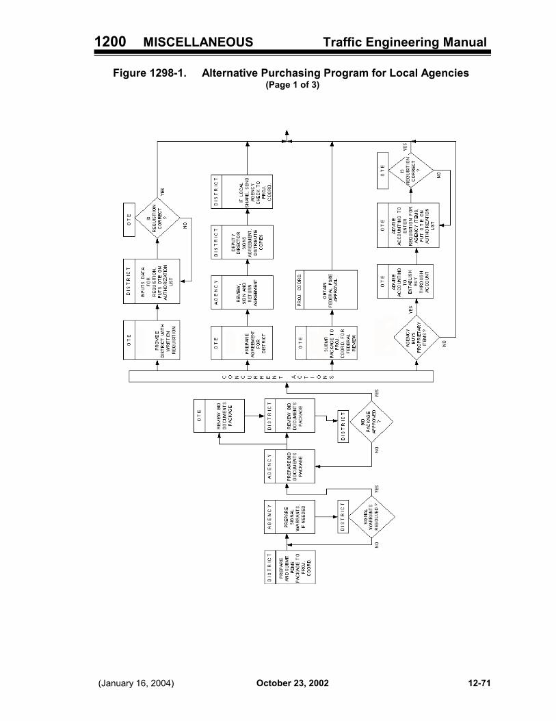
1200 MISCELLANEOUS Traffic Engineering Manual
October 23, 2002(January 16, 2004) 12-71
Figure 1298-1. Alternative Purchasing Program for Local Agencies (Page 1 of 3)

1200 MISCELLANEOUS Traffic Engineering Manual
October 23, 2002 (January 16, 2004)12-72
Figure 1298-1 continued (Page 2 of 3)

1200 MISCELLANEOUS Traffic Engineering Manual
October 23, 2002(January 16, 2004) 12-73
Figure 1298-1 continued (Page 3 of 3)

1200 MISCELLANEOUS Traffic Engineering Manual
October 23, 2002 (January 16, 2004)12-74
Figure 1298-2. Ball Bank Indicator

1200 MISCELLANEOUS Traffic Engineering Manual
October 23, 2002(January 16, 2004) 12-75
Figure 1298-3. Local Government Agency / Utility Force Account Work

1200 MISCELLANEOUS Traffic Engineering Manual
October 23, 2002 (January 16, 2004)12-76
Figure 1298-4. Sample Letter Requesting Alternate Bids

1200 MISCELLANEOUS Traffic Engineering Manual
October 23, 2002(January 16, 2004) 12-77
Figure 1298-5. Sample Letter Stating Local Decision on Alternate Bids

1200 MISCELLANEOUS Traffic Engineering Manual
October 23, 2002 (January 16, 2004)12-78
Figure 1298-6. Sample Safety Study Table of Contents
TABLE OF CONTENTS
Page
Title Page . . . . . . . . . . . . . . . . . . . . . . . . . . . . . . . . . . . . . . . . . . . . . . . . . . . . . . . . . . . . . . . . . 1
Executive Summary . . . . . . . . . . . . . . . . . . . . . . . . . . . . . . . . . . . . . . . . . . . . . . . . . . . . . . . 2
i) Purpose . . . . . . . . . . . . . . . . . . . . . . . . . . . . . . . . . . . . . . . . . . . . . . . . . . . . . . . . . . . . . 2ii) Background . . . . . . . . . . . . . . . . . . . . . . . . . . . . . . . . . . . . . . . . . . . . . . . . . . . . . . . . . . 3iii) Brief Overview of Possible Causes . . . . . . . . . . . . . . . . . . . . . . . . . . . . . . . . . . . . 3iv) Recommended Countermeasures and Related Costs . . . . . . . . . . . . . . . . . . 4
Existing Conditions . . . . . . . . . . . . . . . . . . . . . . . . . . . . . . . . . . . . . . . . . . . . . . . . . . . . . . . 5
i) Condition Diagram . . . . . . . . . . . . . . . . . . . . . . . . . . . . . . . . . . . . . . . . . . . . . . . . . . . . 6ii) Physical Condition Writeup . . . . . . . . . . . . . . . . . . . . . . . . . . . . . . . . . . . . . . . . . . . . 9
Collision Diagram . . . . . . . . . . . . . . . . . . . . . . . . . . . . . . . . . . . . . . . . . . . . . . . . . . . . . . . . 10
Crash Data . . . . . . . . . . . . . . . . . . . . . . . . . . . . . . . . . . . . . . . . . . . . . . . . . . . . . . . . . . . . . . . 14
Crash Analysis . . . . . . . . . . . . . . . . . . . . . . . . . . . . . . . . . . . . . . . . . . . . . . . . . . . . . . . . . . . 16
Recommendations . . . . . . . . . . . . . . . . . . . . . . . . . . . . . . . . . . . . . . . . . . . . . . . . . . . . . . . 19
Rate of Return . . . . . . . . . . . . . . . . . . . . . . . . . . . . . . . . . . . . . . . . . . . . . . . . . . . . . . . . . . . 21
Photos . . . . . . . . . . . . . . . . . . . . . . . . . . . . . . . . . . . . . . . . . . . . . . . . . . . . . . . . . . . . . . . . . . . 23
Other Issues . . . . . . . . . . . . . . . . . . . . . . . . . . . . . . . . . . . . . . . . . . . . . . . . . . . . . . . . . . . . . 26
Appendix

1200 MISCELLANEOUS Traffic Engineering Manual
October 23, 2002(January 16, 2004) 12-79
Figure 1298-7 Sample Safety Study Title Page
SAFETY STUDYLIC CO: SR. 310 AND CR. 25 (Morse Rd.)
Dist. 51999 HCLIS #26
Completed By:Completion Date:

1200 MISCELLANEOUS Traffic Engineering Manual
October 23, 2002 (January 16, 2004)12-80
Figure 1298-8. Sample Condition Diagram - Section

1200 MISCELLANEOUS Traffic Engineering Manual
October 23, 2002(January 16, 2004) 12-81
Figure 1298-9. Sample Condition Diagram - Intersection

1200 MISCELLANEOUS Traffic Engineering Manual
October 23, 2002 (January 16, 2004)12-82
Figure 1298-10. Collision Diagram for an Intersection

1200 MISCELLANEOUS Traffic Engineering Manual
October 23, 2002(January 16, 2004) 12-83
Figure 1298-11. Collision Diagram for a Section

1200 MISCELLANEOUS Traffic Engineering Manual
October 23, 2002 (January 16, 2004)12-84
Figure 1298-12. Sample Collision Diagram

1200 MISCELLANEOUS Traffic Engineering Manual
October 23, 2002(January 16, 2004) 12-85
Figure 1298-13. Sample Crash Analysis

1200 MISCELLANEOUS Traffic Engineering Manual
October 23, 2002 (January 16, 2004)12-86
Figure 1298-14. Sample Rate of Return Worksheet

1200 MISCELLANEOUS Traffic Engineering Manual
October 23, 2002(January 16, 2004) 12-87
Southbound Approach at 600 feet - Photo 2
Southbound Approach at 200 feet - Photo 1
Figure 1298-15. Sample Photos for a Safety Study

1200 MISCELLANEOUS Traffic Engineering Manual
October 23, 2002 (January 16, 2004)12-88
Southbound Approach at 1000 feet- Photo 3
Northbound Approach at 200 feet- Photo 4
Figure 1298-16. Sample Photos for a Safety Study

1300 APPENDIX Traffic Engineering Manual
October 23, 2002Revised January 16, 2004 13-1
TABLE OF CONTENTS
Part 13 - APPENDIX
1300 GENERAL . . . . . . . . . . . . . . . . . . . . . . . . . . . . . . . . . . . . . . . . . . . . . . 13-3
1301 DEFINITIONS . . . . . . . . . . . . . . . . . . . . . . . . . . . . . . . . . . . . . . . . . . . 13-31301-1 General . . . . . . . . . . . . . . . . . . . . . . . . . . . . . . . . . . . . . . . . . . . . . . . . . . . 13-31301-2 Acronyms and Abbreviations . . . . . . . . . . . . . . . . . . . . . . . . . . . . . . . . . 13-31301-3 Words and Phrases . . . . . . . . . . . . . . . . . . . . . . . . . . . . . . . . . . . . . . . . . 13-6
1305 FREQUENTLY ASKED QUESTIONS (FAQs) . . . . . . . . . . . . . . . . . 13-37
1310 ODOT DIRECTIVES . . . . . . . . . . . . . . . . . . . . . . . . . . . . . . . . . . . . . 13-39
1311 OTHER OTE POLICIES, GUIDELINES & STANDARD PROCEDURES . . . . . . . . . . . . . . . . . . . . . . . . . . . . . . . . . . . . . . . . . . . . . . . . . . . . . 13-41
1312 OTHER ODOT POLICIES, GUIDELINES & STANDARD PROCEDURES. . . . . . . . . . . . . . . . . . . . . . . . . . . . . . . . . . . . . . . . . . . . . . . . . . . . . 13-43
1313 OTE FORMS . . . . . . . . . . . . . . . . . . . . . . . . . . . . . . . . . . . . . . . . . . . 13-45
1314 OTHER ODOT FORMS . . . . . . . . . . . . . . . . . . . . . . . . . . . . . . . . . . 13-45
1396 FORMS INDEX - no forms at this time . . . . . . . . . . . . . . . . . . . . . . 13-47
1399 INDEX OF RESOURCE MATERIALS INCLUDED . . . . . . . . . . . . . . 13-49

1300 APPENDIX Traffic Engineering Manual
October 23, 2002 (January 16, 2004)13-2
Intentionally blank.
1300 APPENDIX Traffic Engineering Manual
October 23, 2002Revised January 16, 2004 13-3
Part 13 - APPENDIX
1300 GENERAL
This Part will be used to provide additional or supplementary material that may be useful for those usingthis Manual. Copies of separate policies, guidelines and standard operating procedures referencedin other sections are included herein.
1301 DEFINITIONS
1301-1 General
Generally, for traffic control purposes, the definitions found in the OMUTCD will apply. Also, for designpurposes, there are additional definitions provided in the three volumes of the L&D Manual. Additionaldefinitions, including explanations of various acronyms, have been provided in this section. For theconvenience of the TEM users, some definitions found in the L&D Manual have been included;however, definitions found in the OMUTCD have not been repeated unless there is a difference notedbetween the way the term is used for traffic control purposes versus design purposes.
1301-2 Acronyms and Abbreviations
Some of these acronyms and abbreviations may not be used in the TEM at this time; however, theyare provided here as a convenience since they may appear in other related references.
AAN - American Association of Nurserymen.
AASHTO - American Association of State Highway and Transportation Officials.
ACI - American Concrete Institute.
ADA - Americans with Disabilities Act.
AISC - American Institute of Steel Construction.
AISI - American Iron and Steel Institute.
ANSI - American National Standards Institute.
AREA - American Railway Engineering Association.
ASCE - American Society of Civil Engineers.
ASM - Application Standards Manual. A manual previously published by OTE which wasincorporated into the TEM.
ASME - American Society of Mechanical Engineers.
ASTM - American Society of Testing and Materials.
ATSSA - American Traffic Safety Services Association.

1300 APPENDIX Traffic Engineering Manual
October 23, 2002 Revised January 16, 200413-4
AWG - American Wire Gauge.
AWS - American Welding Society.
AWWA - American Water Works Association.
AWPA - American Wood Preservers’ Association.
CGM - Construction Guidelines Manual. A manual which was previously published by OTEwhich was incorporated into the TEM.
DDD - ODOT District Deputy Director.
CADD - Computer-Aided Drafting and Design. See Section 1301-3 for additional information.
CMS - Construction and Materials Specifications Book. See Part 1 for additional informaiton.
EEI - Edison Electric Institute.
EPA - Environmental Protection Agency.
FHWA - Federal Highway Administration, Department of Transportation.
FSS - Federal Specifications and Standards from the General Services Administration.
GLCT - Great Lakes Circle Tour. See Part 2 for additional information.
GSDM - Guide Sign Design Manual (also known as the Design Manual for Directional GuideSigns). A manual previously published by OTE. The information is now located in Appendix C ofthe Sign Design Manual, which is incorporated by reference into the TEM.
HCM - Highway Capacity Manual.
IEEE - Institute of Electrical and Electronic Engineers.
IES - Illuminating Engineering Society.
IMSA - International Municipal Signal Association.
IPCEA - Insulated Power Cable Engineers Association.
ISSA - International Slurry Seal Association.
ITS America - Intelligent Transportation Society of America
ITE - Institute of Transportation Engineers.
L&D Manual - Location and Design Manual. A three-volume set of design manuals publishedby the Office of Roadway Engineering Services (Volume One), the Office of StructuralEngineering (Volume Two) and the Office of Production (Volume Three).
LECT - Lake Erie Circle Tour. See Part 2 for additional information.

1300 APPENDIX Traffic Engineering Manual
October 23, 2002(January 16, 2004) 13-5
LOS - Level of Service. See Section 1301-3 and the L&D Manual Volume One, for additionalinformation.
L.C.L. - Light Center Length. See Section 1301-3 for additional information.
LEO - Law Enforcement Officer.
LPA - Local Public Agency.
LTAP - Local Transportation Assistance Program. See Section 1301-3 for additionalinformation.
MUTCD - Manual on Uniform Traffic Control Devices. This manual, published by FHWA, isdescribed in Section 193-10.
NCUTCD - National Committee on Uniform Traffic Control Devices. See Section 1301-3 foradditional information.
NEMA - National Electrical Manufacturers Association. See Section 1301-3 for additionalinformation.
OCA - Office of Construction Administration.
ODNR - Ohio Department of Natural Resources.
ODOT - Ohio Department of Transportation.
OMUTCD - Ohio Manual of Uniform Traffic Control Devices. See Section 101 for additionalinformation.
OPI - Ohio Penal Industries.
ORC - Ohio Revised Code.
ORDC - Ohio Rail Development Commission.
OSHA - Occupational Safety and Health Administration.
OTE - Office of Traffic Engineering.
O.L. - Overall Length. See Section 1301-3 for additional information.
PIS - Plan Insert Sheets. See Section 104 for additional information.
PS&E - Plans, Specifications & Estimates. See Section 1301-3 for additional information.
RAM - Random Access Memory. See Section 1301-3 for additional information.
REA - Rural Electrification Administration
ROM - Read Only Memory. See Section 1301-3 for additional information.
RPM - Raised Pavement Marker. See Section 1301-3 for additional information.

1300 APPENDIX Traffic Engineering Manual
October 23, 2002 Revised January 16, 200413-6
SCD - Standard Construction Drawing. See Section 1301-3 for additional information.
SDM - Sign Design Manual. The Standard Sign Design Manual is described in Section 295-2.
SHS - Standard Highway Signs. This manual, published by FHWA, is described in Section193-15.
SOP - Standard Operating Procedure.
SSPC - Steel Structures Painting Council.
SLD - Straight Line Distance. See Section 1301-3 for additional information.
SLM - Straight Line Mileage. See Section 1301-3 for additional information.
TCD - Traffic Control Device.
TCDIM - Traffic Control Design Information Manual. A manual previously published by OTEwhich has been incorporated into the TEM.
TCP - Traffic Control Plan.
TEM - Traffic Engineering Manual.
TODS - Tourist Oriented Directional Signs. See Section 1301-3 and Part 2 for additionalinformation.
TRPM - Temporary Raised Pavement Marker.
UL - Underwriters’ Laboratories, Inc.
1301-3 Words and Phrases
OMUTCD Section 1A.13 defines various terms used in that manual and herein. When the source ofthe definition is the ORC (usually Section 4511.01), the definition is shown in italics and the ORCsection number is noted. The following list is intended to provide definitions of words and phrases notcurrently defined in the OMUTCD.
Some of the definitions in this section will be incorporated into the OMUTCD; however, most of themare more detailed than needed for the OMUTCD. The source for most of these definitions was theConstruction Guidelines Manual, previously published by OTE and now incorporated into the TEM.When definitions have been taken from other sources, such as the national Manual on UniformTraffic Control Devices (MUTCD) and the ODOT L&D Manuals, they have been identified by across-reference.
Also, some of the terms noted herein may have different meanings depending on the context in whichthey are used. Clarification has been provided as needed.
Adaptation - The process by which the retina becomes accustomed to more or less light than itwas exposed to during an immediately preceding period.
Adjustable Signal - A signal head having the signal faces mounted in the support hardware sothat each face may be adjusted or “aimed,” as required to present the indication to approachingtraffic.

1300 APPENDIX Traffic Engineering Manual
October 23, 2002Revised January 16, 2004 13-7
Alternate Bid - A bid process in which both a generic bid and a proprietary bid are taken for thesame item of equipment or work. The maintaining agency may choose which bid to accept;however, if the agency chooses the proprietary bid and it is higher than the generic bid, it mustuse its own funds for 100 percent of the cost difference.
Amplifier - A device that is capable of intensifying the electrical energy produced by a sensor.
Analog Controller - A controller with a method of timing that measures continuous variables suchas voltage or current.
Arterial Highway (or Street) - For traffic engineering purposes (ORC 4511.01 and OMUTCD),any U.S. or State numbered route, controlled-access highway, or other major radial orcircumferential street or highway designated by local authorities within their respective jurisdictionsas part of a major arterial system of streets or highways.
For design purposes, a functional classification for a facility primarily used for through traffic,usually on a continuous route (L&D Manual Volume One).
Attenuator (Crash Cushion) - Protective device that prevents errant vehicles from impacting afixed object by gradually decelerating or redirecting the vehicle (L&D Manual Volume One).
Auto-Manual Switch - See Switch, Auto-Manual.
Auxiliary Equipment - Separate control devices used to add supplementary features to a signalcontroller.
Balance Adjuster - A device used to permit alignment of the point of suspension with respect tothe center of gravity of the signal head so that the signal will hang vertically.
Ballast - An auxiliary device used with vapor lamps, on multiple circuits, to provide properoperating characteristics. It limits the current through the lamp, and may also transform voltage.
Ballast Mounting - Ballast shall be mounted within the luminaire housing (integral).
Bandwidth - The amount of green time available to a platoon of vehicles in a progressive signalsystem. This is also referred to as through band.
Barrier - A longitudinal device used to shield drivers from natural or manmade obstacles along theroadway. Occasionally used to protect others (pedestrian, bicyclists, etc.) from vehicular traffic(L&D Manual Volume One).
Barrier (Compatibility Line) - A reference point in the preferred sequence of a multi-ringcontroller unit at which all rings are interlocked. Barriers assure three will be no concurrentselection and timing of conflicting phases for traffic movement in different rings. All rings crossthe barrier simultaneously to select and time phases on the other side (NEMA).
Barrier Clearance - The distance required between the face of a barrier and the face of anobstacle to permit adequate shielding (L&D Manual Volume One).
Barrier Curb - See Curb, Vertical.
Base Plates - In sign support breakaway connections, plates welded onto each beam half withskewed notches for torqued bolts so as to permit the plates to part under vehicle impact.

1300 APPENDIX Traffic Engineering Manual
October 23, 2002 (January 16, 2004)13-8
Bead Flotation - The ability of glass beads to assume a hemispheric secured position whendispensed onto the surface of the freshly applied pavement markings.
Beam Candlepower - The intensity of a beam forming light source expressed in candelasmeasured in a given direction.
Beam Spread - The angle between the two directions in the plane in which candlepower is equalto a stated percent (usually 10 percent) of maximum candlepower in the beam.
Beam-Type Support - See Support, Beam-Type.
Bearing Plate - A formed steel plate installed between a flatsheet sign and its mounting post soas to reinforce the sign.
Bid, Alternate - See Alternate Bid.
Bid, Generic - See Generic Bid.
Bid, Proprietary - See Proprietary Bid.
Binder - Resins and liquids used to combine dry ingredients into a formulation of pavementmarking materials.
Bleeding - A condition where asphalt pavement surfaces soften to a point where released oilsappear as strains in the marking.
Bracket Arm - A signal bracket, for bracket-mount applications, of tubular construction throughwhich wiring can be passed to provide electrical connection of the signal faces.
Breakaway Beam-Type Support - See Support, Breakaway Beam-Type.
Burning position - Physical positioning of the lamp in the traffic signal. Normally, traffic signallamps are used in horizontal burning position.
Cable - A group of separately insulated wires in a common jacket.
Cable Entrance Adapter - A device of tubular construction which is used between the span wirehanger and the traffic signal to provide for passing signal cable into the head.
CADD (Computer-Aided Drafting and Design) - The preferred method of preparing constructionplans for the ODOT. ODOT has adopted MicroStation as its standard CADD software packageand has developed various CADD standards to ensure plan uniformity.
Call - A registration of demand for right-of-way by traffic (vehicular or pedestrian) at a signalcontroller.
Calling Detector - A detector that is installed in a selected location to detect vehicles which maynot otherwise be detected, and whose output may be modified by the controller unit.
Calling Relay - A detector relay which will allow a detector actuation to be transferred to thecontroller only when certain signal displays are occurring.
Camber - An upward curve in horizontal structural members so that when erected and under deadweight a horizontal position or slightly upward curve will result.

1300 APPENDIX Traffic Engineering Manual
October 23, 2002Revised January 16, 2004 13-9
Camshaft - A device consisting of a stack of programmed cams operated by a drive motor forintermittent advancement in increments to cause contacts to open or close, thus causing therequired signals to be energized.
Candela (cd) - The unit of luminous intensity; one candela is defined as the luminous intensityof 1/60th of one square centimeter of projected area of a blackbody radiator operating at thetemperature of solidification of platinum.
Candlepower - Luminous intensity expressed in candelas.
Cantilever Support - See Support, Cantilever.
Carryover (Extended) Output - The ability of a detector to continue its output for apredetermined length of time following an actuation.
Catch Basin - A structure for intercepting flow from a gutter or ditch and discharging the waterthrough a conduit (L&D Manual Volume Two).
Centerline of Construction - The reference line used for construction of a project. Normallylocated at the median centerline on a divided highway or at the normal crown point location on anundivided highway (L&D Manual Volume Three).
Centerline of Right-of-Way - The reference line used for the right-of-way of a project. Normallylocated at the center of a highway’s existing right-of-way (L&D Manual Volume Three).
Centerline of Survey - The reference line used in the field survey of a project. Although it isusually the same as the centerline of construction, it may be a separate survey line establishedfor convenience. With modern surveying instruments, surveys are no longer completed based ona centerline of survey (L&D Manual Volume Three).
Center-Mount Support - See Support, Center-Mount.
Centralized Control Signal System - A system in which all control functions are controlled bya computer with direct communication to each local intersection controller without using theintermediate control and processing of a master controller.
City - A municipal corporation having a population of 5,000 or more persons (ORC Section703.1).
Classification Detector - A detector that has the capability of differentiating among types ofvehicles.
Clear Zone - The area along a highway beyond the edge of pavement and available for safe useby errant vehicles (L&D Manual Volume One).
The total roadside border area, starting at the edge of the traveled way, that is wide enough toallow an errant driver to stop or regain control of a vehicle. This area might consist of a shoulder,a recoverable slope, and/or a nonrecoverable, traversable slope with a clear run-out area at its toe(OMUTCD).
Cloverleaf Interchange - An interchange with loop ramps and outer ramps for directionalmovements. A full cloverleaf has ramps in every quadrant (L&D Manual Volume One).
Collector Highway (or Street) - A functional classification for a facility in an intermediate

1300 APPENDIX Traffic Engineering Manual
October 23, 2002 Revised January 16, 200413-10
functional category connecting smaller local road or street systems with larger arterial systems(L&D Manual Volume One).
A term denoting a highway that in rural areas connects small towns and local highways to arterialhighways, and in urban areas provides land access and traffic circulation within residential,commercial and business areas and connects local highways to the arterial highways (OMUTCD).
Coefficient of Utilization (CU) - Ratio of luminous flux (lumens) received on the work area to therated lumens emitted by the lamp.
Collector-Distributor (C-D) - A directional roadway adjacent to a freeway used to reduce thenumber of conflicts (merging, diverging and weaving) on the mainline facility (L&D ManualVolume One).
Commercial Activity - For purposes of defining Tourist Oriented Activity for the TODS program,this is defined as a farm market, winery, a bed and breakfast, lodging that is not a franchise orpart of a national chain, antiques shop, craft store, or gift store.
Computed Initial Portion (Added Initial Portion, Variable Initial Portion) - An initial portionwhich is added to the minimum actuations on volume density timed controllers.
Computer - A device capable of accepting information, applying prescribed processes to theinformation and supplying results of these processes. It usually consists of input and outputdevices, storage, arithmetic and logic units, and a control unit.
Computer Program - A series of instruction or statements in a form acceptable to the computerwhich will achieve a certain result.
Concurrent timing - See Dual-ring Controller.
Conduit - An artificial or natural channel; usually a closed structure such as a pipe (L&D ManualVolume Two).
Condulet - A fitting connected to solid or flexible electrical conduit to direct the routing path andcontaining a removable cover for wire pulling.
Conflicting Phases - Two or more signal phases which will cause interfering, or conflicting, trafficmovements if operated concurrently.
Congestion Detection - A system of hardware and software designed and operated to providedata on the level of traffic congestion in the area being detected.
Contact, Signal Circuit - A device arranged to energize or de-energize signal light circuits duringa specified interval.
Continuous Presence Mode - Detector outputs continue if any vehicle (first or last remaining)remains in the field of influence.
Controller (Controller Assembly) - A complete electrical or electronic device mounted in acabinet for controlling the operation of a traffic signal (OMUTCD).
Controller, Local Intersection - See Local Intersection Controller.
Controller, Master - See Master Controller.

1300 APPENDIX Traffic Engineering Manual
October 23, 2002Revised January 16, 2004 13-11
Controller, Traffic-Actuated - See Traffic-Actuated Controller.
Construction Limits - Lines shown on a plan view that outline the lateral extent of the work.Typically placed 4 feet (1.2 meters) outside the point where the backslope touches the existingground unless additional room is required for construction activities (L&D Manual Volume Three).
Controlled Access - Highway right-of-way where preference is given to through traffic. Inaddition to access connections with selected public roads, there may be some private driveconnections (L&D Manual Volume One).
Controlled-Access Highway (Partial Control of Access) - Every highway, street or roadwayin respect to which owners or occupants of abutting lands and other persons have no legal rightof access to or from the same except at such points only and in such manner as may bedetermined by the public authority having jurisdiction over such highway, street or roadway (ORC4511.01 and OMUTCD).
Converging Roadway - Separate and nearly parallel roadways or ramps which combine into asingle continuous roadway or ramp having a greater number of lanes beyond the nose than thenumber of lanes on either approach roadways (L&D Manual Volume One).
Coordinator (Coordination Unit) - A device used to interrelate the timing of one controller toothers in a traffic signal system.
Coordination - See Signal Coordination.
Crash Cushion - See Attenuator.
Crashworthy - A characteristic of a roadside appurtenance that has been successfully crashtested in accordance with a national standard such as the National Cooperative Highway ResearchProgram Report 350, “Recommended Procedures for the Safety Performance Evaluation ofHighway Features” (MUTCD).
Culvert - A structure, as distinguished from a bridge, which is usually covered with embankmentand is composed of structural material around the entire perimeter, although some are supportedon spread footings with the streambed serving as the bottom of the culvert. Also, a structure whichis 20 feet (6.1meters) or less in roadway centerline length between extreme ends of openings formultiple cell structures (L&D Manual Volume Two).
Curb, Sloping - Sloping curbs are designed so vehicles can cross them readily when the needarises. They are low with flat sloping faces. Total curb height should not exceed 6 inches (150millimeters). Formerly called Mountable Curb (AASHTO).
Curb, Vertical - Vertical curbs may be either vertical or nearly vertical and are intended todiscourage vehicles from leaving the roadway. The curb height ranges from 6 to 8 inches (150 to200 millimeters). Formerly called Barrier Curb (AASHTO).
Cycle - Any complete sequence of signal indications.
Cycle Selection Switch - A device which when operated discontinues automatic selection ofcycle unit with associated split(s) and offset(s) and permits manual selection of another cycle unit.
Daylight Reflectance - The measure of daylight reflected from a pavement marking for theenhancement of visibility.

1300 APPENDIX Traffic Engineering Manual
October 23, 2002 Revised January 16, 200413-12
Decoder - A mechanism for translating a code into its various components.
Decision Sight Distance - The distance required for a driver to detect an unexpected orotherwise difficult-to-perceive information source or hazard in a roadway environment that maybe visually cluttered, recognize the hazard or its threat potential, select an appropriate speed andpath, and initiate and complete the required maneuver safely (L&D Manual Volume One).
Dedicated Lines - Communication lines used solely to interconnect two or more intersections.
Delayed Output - The ability of a detector to delay its output for a predetermined length of timeduring an extended actuation.
Delay Relay - A detector relay which will provide an actuation only after the relay has beencontinuously energized for a set period of time.
Delineator - A retroreflective device mounted on the roadway surface or at the side of theroadway in a series to indicate the alignment of the roadway, especially at night or in adverseweather (MUTCD).
Demand - The need for service, e.g., the number of vehicles desiring to use a given segment ofroadway during a specified unit of time.
Demountable Copy - Sign copy made up of separate letters, digits, symbols, shields and bordersections which are riveted or bolted to the sign panel and which may be readily removed.
Density - A measure of the number of vehicles per unit length of roadway; a measure of theconcentration of vehicles usually stated as the number of vehicles per mile (kilometer) per lane.
Department - The Ohio Department of Transportation.
Design Exception - A document which explains the engineering reasons for allowing certaindesign criteria to be relaxed in extreme unusual circumstances (L&D Manual Volume One).
Design Hour - The 30th highest hourly volume of the design year (L&D Manual Volume One).
Design Hourly Volume - The total volume of traffic in the design hour, usually a forecast of peakhour volume, measured in vehicles per hour (L&D Manual Volume One).
Design Speed - The maximum safe speed that can be maintained over a specified section ofhighway when conditions are so favorable that the design features of the highway govern (L&DManual Volume One).
Destination Signs - Signs providing distance and/or directional information to a city, village orother objective.
Detectable - Having a continuous edge within 150 mm (6 in) of the surface so that pedestrianswho have visual disabilities can sense its presence and receive usable guidance information(MUTCD).
Detections - The process used to identify the presence or passage of vehicles at a specific pointor to identify the presence of one or more vehicles in a specific area.
Detector Modes - A term used to describe the duration of detector output when a detectionoccurs.

1300 APPENDIX Traffic Engineering Manual
October 23, 2002(January 16, 2004) 13-13
Diagnostic - (1) Pertaining to the detection, discovery and further isolation of a malfunction ormistake; (2) A program that facilitates computer maintenance by detection and isolation ofmalfunctions or mistakes.
Diamond Interchange - The simplest and most common type of interchange, formed when one-way diagonal ramps are provided in each quadrant and left turns are provided on the minorhighway (L&D Manual Volume One).
Diffuser - A device to redirect or scatter the light from a source, primarily by the process ofdiffuse transmission.
Digital Controller - A controller wherein timing is based upon a defined frequency source suchas a 60-hertz alternating power source.
Digital Timing - See Timing, Digital.
Dilemma Zone - The range of distances from the Stop Line within which drivers are indecisive asto whether to stop or proceed through the intersection when the traffic signal indication changesfrom green to yellow. Distances are dependent upon travel speed.
Directional Interchange - An interchange, generally having more than one grade separation, withdirect connections for all movements (L&D Manual Volume One).
Direct Applied Copy - Sign copy cut from sheeting material and applied to the sign surface bya coated adhesive.
Direct Glare - Glare resulting from high brightnesses or insufficiently shielded light sources in thefield of view or from reflecting areas of high brightness.
Direct Wire - A communications medium which uses hardware interconnect between thetransmission and reception points.
Directional Detector (or Relay) - A detector that is capable of being actuated only by vehiclesproceeding in one specified direction.
Directional Relay - A relay connected with detectors and designed to actuate only when traffichas crossed the detectors in a certain direction.
Disability Glare - Glare which reduces visual performance and visibility and which is oftenaccompanied by discomfort.
Discomfort Glare - Glare which produces discomfort. It does not necessarily interfere with visualperformance or visibility.
Disconnect Hanger - A mounting device for quick detachment or attachment of a signal head.
Distributed Control Signal System - A system in which all control functions are controlled bya master controller which is connected to all local intersections under its control. The mastercontroller is typically located at an on-street location near the local intersection it controls. Themaster controller is connected to a computer to enable an operator to control, monitor andproduce reports from each master controller database.
Divergence Angle - The angle at a reflective surface between a light ray striking the surface andan observer’s line of sight.

1300 APPENDIX Traffic Engineering Manual
October 23, 2002 Revised January 16, 200413-14
Diverging Roadway - Where a roadway branches or forks into two separate roadways withoutthe use of a speed change lane (L&D Manual Volume One).
Down Time - The time during which a device is unavailable for normal operation.
Drop-on Beads (Surface Applied Beads) - Glass beads dispensed concurrently with wet ormolten marking material placement so that the beads are held on the surface to provideinstantaneous reflectorization.
Dual Entry - See Entry, Dual.
Dual-ring Controller - A controller containing two interlocked rings which are arranged to timea preferred sequence and to allow concurrent timing of both rings, subject to the restraint in theBarrier (Compatibility Line).
Dummy Interval - A redundant interval in the cam switching mechanism incorporated so as toallow the total number of intervals in the cycle to correspond integrally with the total number ofintervals provided on the cam switching mechanism.
Dwell - See Rest.
Edge of Pavement - See Pavement Edge.
Electromechanical Controller - A controller which is characterized by electrical circuits usingrelays, step switches, motors, etc.
Electromechanical Electronic Controller - A controller combining electromechanicalcomponents and electronic timing circuits comprised of vacuum electronic tubes, resistors,capacitors and inductors, etc.
Emergency-Traffic Signal - A special adaptation of a traffic control signal to obtain the right-of-way for an authorized emergency vehicle.
Encoder - A device which converts data into a form for transmission over the communication linkbetween two points in a system.
Entrance Ramp Approach Signs - Signs at a freeway or expressway interchange providing stateroute identification and directional information.
Entry, Dual - A mode of operation (in a dual-ring controller) in which one phase in each ring mustbe in service. If a call does not exist in a ring when it crosses the barrier, a phase is selected inthat ring to be activated by the controller in a predetermined manner.
Entry, Single - A mode of operation (in a dual-ring controller) in which a phase in one ring canbe selected and timed alone if there is no demand for service in a non-conflicting phase on aparallel ring.
Epoxy Markings - A mixture of epoxy resin and polymeric curing agent blended in a nozzle andspray applied to the pavement.
Expressway - For purposes of the traffic control standards (ORC 4511.01 and OMUTCD), “adivided, arterial highway for through traffic with full or partial control of access with an excess offifty percent of all crossroads separated in grade.”

1300 APPENDIX Traffic Engineering Manual
October 23, 2002Revised January 16, 2004 13-15
For design purposes (L&D Manual Volume One), “a divided, arterial highway with full or partialcontrol of access and generally with grade separations at major intersections.”
Extendible Portion (Extensible Portion) - That portion of the green interval on an actuatedphase following the initial portion which may be extended by traffic actuations.
Extension Detector - A detector that is arranged to register actuation at the controller only duringthe green interval for that approach so as to extend the green time of the actuating vehicles.
Extension Interval (Gap) - The timing interval during the extendible portion which is resettableby each detector actuation. The green right-of-way of the phase may terminate on expiration ofthe unit extension time.
Extension Limit - See Limit, Extension.
Extruded Markings - Pavement markings applied in a plastic state by means of a shaping die.
Extrusheet Sign - See Sign, Extrusheet.
Field Terminal Blocks - See Terminal Blocks, Field.
Filament - The electrical resistance element heated to incandescence by electric current.
Fill Slope - See Foreslope.
Filler - An ingredient adding bulk to the formulations of pavement marking materials.
Flash Control Switch - See Switch, Flash Control.
Flasher Controller - A complete electrical mechanism with cabinet for flashing a traffic signal orbeacon.
Flatsheet Sign - See Sign, Flatsheet.
Footcandle (fc) - The unit of illumination when the foot is the unit of length; the illumination on asurface one square foot in area on which there is a uniformly distributed flux of one lumen. Itequals one lumen per square foot.
Footlambert (fl) - The unit of brightness equal to the uniform brightness of a perfectly diffusingsurface emitting or reflecting light at the rate of one lumen per square foot. On a roadway, itequals the illumination in footcandles multiplied by the reflection factor of the surface.
Force Account - The direct performance of highway construction work by a highway agency, arailroad company or a public utility company by use of labor, equipment, materials and suppliesfurnished by them and used under their direct control.
For a construction project, force account is defined as a basis of payment for the directperformance of highway construction work with payment based on the actual cost of labor,equipment and materials furnished.
Force Off - A command to the controller that will force the termination of the current right-of-wayinterval during the extendible portion.
Force Skip - See Omit, Phase.

1300 APPENDIX Traffic Engineering Manual
October 23, 2002 Revised January 16, 200413-16
Foreslope - The slope from the edge of the graded shoulder to the bottom of the ditch. Also, calledFill Slope (L&D Manual Volume One).
Freeway - For traffic control purposes (ORC 4511.01 and OMUTCD), “a divided multi-lanehighway for through traffic with all crossroads separated in grade and with full control of access.”
For design purposes (L&D Manual Volume One), “an expressway with full access control andno at-grade intersections.”
Full-Actuated Controller - A type of actuated controller in which means are provided for trafficactuation on all approaches to the intersection.
Full-circle Tunnel Visor - A visor which encircles the entire lens.
Functional Classification - The grouping of highways by the character of service they provide(L&D Manual Volume One).
Fuse Plate - See Plate, Fuse.
Gap, Maximum - The maximum time on volume-density timed controllers allotted for vehicles toproceed through the intersection. The interval portion is decreased to a fixed minimum inproportion to traffic demands.
Gap, Minimum - The lower limit to which the extendible portion of the extension time may bedecreased on volume-density timed controllers.
Gap Reduction - A feature in volume-density controllers whereby the unit extension in the phasehaving the green is reduced in the extendible portion of the interval in proportion to the timevehicles have waited on the phase(s) having the red.
General Notes - A portion of a highway plan containing those plan notes required to clarifyconstruction items not adequately covered by the specifications or plan details (L&D ManualVolume Three).
General Summary - A portion of a highway plan used to summarize the total estimated quantitieswith complete pay item descriptions, item numbers and funding splits (L&D Manual VolumeThree).
Generic (or Generic Bid) - Specified by a generalized material or performance specificationwithout reference to a manufacturer’s brand name or registered trademark.
Generic Motorist Service Signing - Symbolic or word message signs shown in the OMUTCDwhich indicate the type of service, but not the specific name of the facility.
Glare - The sensation produced by brightnesses within the visual field that are sufficiently greaterthan the luminance to which the eyes are adapted to cause annoyance, discomfort, or loss invisual performance and visibility.
Glare Screen - A device used to reduce the amount of headlight glare resulting from opposingtraffic (L&D Manual Volume One).
Glare Shield - A nonreflective vertical extension of a sign designed to mask the direct rays of signlighting fixtures from the eyes of drivers approaching on the opposing roadway.

1300 APPENDIX Traffic Engineering Manual
October 23, 2002Revised January 16, 2004 13-17
Glass Beads - Small spheres which, when exposed on a pavement marking surface, act asrefracting and reflecting elements which return light back to its source.
Glint - The reflection of light from a specular surface.
Gradation - The classification of particle size distribution of dry material as determined by thepassage or retention of portions of a specimen on standard sieves.
Graded Shoulder - The area located between the edge of the pavement and the foreslope (L&DManual Volume One).
Green Interval (Right-of-way) - The operation of a controller in causing traffic signals to displayindications permitting vehicles or pedestrians to proceed in a lawful manner in preference to othervehicles or pedestrians.
Ground-Mounted Support - See Support, Ground-Mounted.
Headlight Sight Distance - The stopping sight distance required on an unlighted sag verticalcurve (L&D Manual Volume One).
Headwall - The structural appurtenance placed at the end of a culvert to control an adjacenthighway embankment and protect the culvert end from undercutting (L&D Manual Volume Two).
Hiding Power - The degree of opaqueness of a marking in masking underlying pavement shades.
Hinge Plate - See Plate, Hinge.
Hold - A command to the signal controller which causes it to retain the existing right-of-wayinterval.
Horizontal Sight Distance - The sight distance available in consideration of various horizontalalignment features, such as, degree of curvature and the horizontal distance to roadsideobstructions (L&D Manual Volume One).
Hybrid Control Signal System - Incorporates features of both the Centralized and DistributedControl Signal Systems.
Illumination (Illuminance) (E) - The density of luminous flux incident on a surface; the quotientof the flux divided by the area of the surface, when the flux is uniformly distributed.
Impact Resistance - The toughness of a material in resisting deformation and fracture due to astriking blow.
Indicator Lights - Visual aides showing actuations and timing of intervals or phases on acontroller for the purpose of programming inspection and maintenance.
Inherently Low Emission Vehicle (ILEV) - Any kind of vehicle that is certified by the U.S.Environmental Protection Agency and that because of inherent properties of the fuel systemdesign, will not have significant evaporative emissions, even if its evaporative emission controlsystem has failed.
Initial Portion - The first timed portion of the green interval in an actuated controller.

1300 APPENDIX Traffic Engineering Manual
October 23, 2002 Revised January 16, 200413-18
Inlaid Markings - Markings of preformed material pressed into the surface of newly placed asphaltconcrete pavement.
In-mixed Beads (Premixed Beads) - Glass beads distributed uniformly through a pavementmarking material to provide continuous reflectorization as the material wears away.
Interconnect - The traffic signal communication network connecting the system master with localintersection controllers.
Interconnected Controller - A controller which operates traffic signals under the supervision ofa master controller.
Interface - A common boundary at which two separate systems or portions of each join orinteract. An interface can be mechanical, as in adjoining hardware surfaces, or it can beelectrical, as in signal level transformation points. Moreover, it can also refer to human andmachine interface and the interaction between man and computer.
Interlock - A feature of electromechanical controllers which maintains the timing dial in step withthe camshaft.
Intersection Sight Distance - The distance needed along the main roadway for a car enteringfrom a cross road to make a left turn onto the main roadway while clearing traffic approachingfrom the left (L&D Manual Volume One and TEM Part 2).
Interstate - Those roadways on the Federal System which have the highest design speeds andthe most stringent design standards (L&D Manual Volume One).
Interval Sequence - The order of appearance of signal indications during successive intervalsof a cycle.
Interval Sequence Chart - A chart designating the order in which the phases of a cycle occurand the associated signal display for each interval.
Item Code - A nine-digit character used to catalogue pay item descriptions (L&D Manual VolumeThree).
Item Master - A list of acceptable item codes and their corresponding pay item descriptions andunits of measure (L&D Manual Volume Three).
Jack - A receptacle in a controller cabinet in which a plug-in device may be inserted.
Lamp - The part of the optical unit which, when energized electrically, provides the optical unitlight source.
Lamp Lumen Depreciation Factor (LLD) - The multiplier to be used in illumination calculationsto relate the initial rated output of light sources to the anticipated minimum rated output based onthe relamping program to be used.
Lateral Clearance - The distance measured horizontally from the edge of pavement to the faceof an object (parapet, abutment, pier, wall, etc.) (L&D Manual Volume One).
Lead-in Cable - The electric cable which serves to connect the sensor to the input of the detectorunit.

1300 APPENDIX Traffic Engineering Manual
October 23, 2002(January 16, 2004) 13-19
Legal Speed - The legislated or agency authorized maximum speed limit on a section of roadway(L&D Manual Volume One).
Legend - Word messages or symbols used on signs to cover specific meanings.
Lens - That part of the optical unit through which light from the light source and reflector passes,and in so doing, is redirected into a prescribed pattern and is filtered to a prescribed color.
Level of Service (LOS) - A qualitative measure describing the operational flow of traffic (L&DManual Volume One).
Light - A form of radiant energy (such as emitted by the sun). For purpose of illuminatingengineering, the energy is evaluated according to its capacity to produce visual sensations.Measurements are based upon a unit of luminous intensity equal to the light emitted by a “standardcandle” in a horizontal direction.
Light Center Length (L.C.L.) - The dimension, in inches (millimeters) from the center of thefilament to the top of the base (including solder on the base eyelet).
Light Sensitive Detector - A detector that uses a light-sensitive device for sensing the passageof an object interrupting a beam of light directed at the sensor.
Lighting Pole - A support provided with necessary internal attachments for wiring and externalattachments for bracket and luminaire.
Limit, Extension - The maximum time of the extendible portion for which actuations on any trafficphase may retain the right-of-way after actuation on an opposing traffic phase.
Limit, Maximum - The maximum green time after an opposing actuation, which may start in theinitial portion.
Limited Access (Full Control of Access) - Highway right-of-way where rights of access ofproperties abutting the highway are acquired, such that all access to and from the highway areprevented except at designated locations (L&D Manual Volume One).
Limited Presence Mode - Detector output continues for a limited period of time if vehicles remainin field of influence.
Load Switch - A device used to switch power to the signal lamps.
Local Transportation Assistance (LTAP) Program - LTAP, or Technology Transfer (T2)Centers have been established in each of the states to provide for the transfer of transportationtechnology and technical assistance to rural and local governments. The mission of the OhioLTAP Center is to provide training, technical assistance, advice and other resources to Ohio'slocal governments, which include cities, counties, townships and villages. The Ohio LTAP Centeris funded through the FHWA and ODOT.
Local Intersection Controller - The complete electrical mechanism mounted in a cabinet forcontrolling signal operation by selecting and timing the various signal head displays. The localintersection controller is located at the individual intersection site.
Local Road - A functional classification used for rural roadways whose primary function is toprovide access to residences, businesses or other abutting properties (L&D Manual VolumeOne).

1300 APPENDIX Traffic Engineering Manual
October 23, 2002 Revised January 16, 200413-20
Local Street - A functional classification used for urban roadways whose primary function is toprovide access to residences, businesses or other abutting properties (L&D Manual VolumeOne).
Logo Sign Panel - A reflectorized sign mounted on the Specific Service Sign showing thetrademark logo, non-trademark logo, legend message or combination thereof for a motorist serviceavailable on a crossroad at or near an interchange.
LOGO Program - The Ohio Logo Signing Program, also known as the Specific Service SignProgram, permits eligible businesses which provide gas, food, lodging, or camping services todrivers to have their logos placed on specific service (logo) signs. See Part 2 for additionalinformation.
Longitudinal Joint - A pavement joint, in the direction of traffic flow, used to control longitudinalcracking on a rigid pavement or the joint formed between adjacent passes of a paver on a flexiblepavement (Pavement Design & Rehabilitation Manual).
Loop Detector - A detector that senses a change of inductance of its inductive loop sensorcaused by the passage or presence of a vehicle near the sensor.
Lumen (lm) - The unit of luminous flux; equal to the flux in a unit solid angle (one steradion) froma uniform point source of one candela. Traffic signal lamp output is rated in lumens.
Luminance (brightness) RATIO - The ratio between the luminances of any two areas in the visualfield.
Luminaire - The complete lighting unit consisting of a lamp or lamps together with the partsdesigned to distribute the light, to position and protect the lamps, and to connect the lamps to thepower supply.
Luminaire Dirt Depreciation Factor (LDD) - The multiplier to be used in illumination calculationsto relate the initial illumination provided by clean new luminaries to the reduced illumination thatthey will provide due to direct collection on the luminaires at the time at which it is anticipated thatcleaning procedures will be instituted.
Luminaire Efficiency - The ratio of the luminous flux leaving a luminaire to that emitted by thelamp or lamps used therein.
Luminaire Support - A bracket or mast arm attachment to a lighting pole from which a luminaireis suspended.
Magnetic Detector - A detector that senses changes in the earth’s magnetic field caused by themovement of a vehicle near its sensor.
Magnetometer Detector - A detector that measures the difference in the level of the earth’smagnetic forces caused by the passage or presence of a vehicle near its sensor.
Maintenance Factor (MF) - The product of the lamp lumen depreciation factor and the luminairedirt depreciation factor (MF = LLD x LDD).
Manual Operation - The operation of a controller assembly by means of a hand-operateddevice(s) (manual pushbutton).
Manual Pushbutton - An auxiliary device for hand operation of a controller.

1300 APPENDIX Traffic Engineering Manual
October 23, 2002Revised January 16, 2004 13-21
Mast Arm - A structural support over the roadway extending from a pole, for the purpose ofsupporting signal heads.
Mast Arm, Flexible Mount - A mast arm mount where the signal head is attached to the mast armby a flexible joint and connector to permit “free swinging” between the signal and the mast arm.
Mast Arm, Rigid Mount - A mast arm mount where the signal head is rigidly affixed to the mastarm to prevent any relative movement between the signal and the arm.
Master Control - Centrally located equipment designed to supervise a number of intersectionsand used to select programs on secondary control equipment to best suit traffic needs.
Master Controller - An automatic device for supervising a system of secondary controllers,maintaining definite time interrelationship, selecting among alternate available modes of operationsor accomplishing other supervisory functions.
Master Coordinator - A coordinator used to provide synchronization and selection of programson secondary coordinators or pretimed controllers to maintain a traffic system.
Master-secondary Controller - A controller for operating a traffic signal and for providingsupervision of other interconnected (secondary) controllers.
Maximum Green - The maximum time right-of-way can be extended by actuation on a phaseprovided an actuation has been registered on a conflicting phase.
Maximum Initial Portion - The limit of the computed initial portion on volume density timedcontrollers.
Maximum Limit - See Limit, Maximum.
Memory, Locking - The retention of an actuation for future utilization by the controller.
Memory, Nonlocking - A mode of actuated-controller operation which does not require detectormemory.
Mercury Vapor Luminaire - A lighting unit containing a mercury vapor lamp mounted within ahousing with a metal frame, glass lens and a reflector.
Microprocessor - A device which uses the flexibility of computer electronics on a limited scale.Microprocessors are basically microminiaturized CPUs (Central Processing Units).
Minimum Green - (1) The shortest time for which the right-of-way shall be given to a non-actuatedphase; (2) The shortest time for which the right-of-way shall be given to an actuated phaseprovided an actuation has been registered for that phase.
Minimum “Initial” Lumens - A minimum value of initial light output below which no more than aspecified percentage of individual lamps will be permitted.
Minimum Initial Portion (Fixed Initial Portion) - A fixed preset first interval portion of the right-of-way on volume-density controllers.
Minor Movement Controller - A device that can be used with a controller unit to providesubordinate phase timing.

1300 APPENDIX Traffic Engineering Manual
October 23, 2002 Revised January 16, 200413-22
Modular - Equipment which is designed such that functional sections are plug-in circuit boardsand can be readily exchanged with similar units.
Modular Controller, by Function - Controllers constructed so that additional functionalcapabilities may be provided by the addition of hardware modules. A single module provides afunction(s) for one or more phases in the controller.
Modular Controller, by Phase - A controller constructed so that each timing module isassociated with only one independent phase. The addition or removal of modules associated withone phase will not affect the operation of the controller with respect to the other phases.
Motorist Services - Signing for the LOGO program (gas, food, lodging or camping), emergencyhospitals, generic motorist services (gas, diesel, food, lodging, camping), tourist informationcenters, law enforcement agencies and motorist assistance.
Mountable Curb - see Curb, Sloping.
Mounting Height (MT. HT.) - The vertical distance in feet (meters) between the roadway surfaceand the center of the light source in the luminaire.
Movement - The travel direction and destination of a lane or lanes of vehicles at an intersection,i.e. left turn, through or right turn.
Multiplexing - A communications technique which allows more than one item of information to betransmitted or received at essentially the same time.
Municipal Corporation - A city or village.
National Committee on Uniform Traffic Control Devices (NCUTCD) - A private organizationof 150 to 200 experts who are involved in the daily operation of highways or streets. The committeemeets twice a year to discuss proposed changes to the national MUTCD, develop comments, andsubmit them to FHWA for consideration. Its current members are employees of State and localagencies directly involved with traffic engineering activities, or representatives of otherorganizations who have a major interest in traffic control issues.
National Electrical Manufacturers Association (NEMA) - A national association of signalequipment and electrical component manufacturers that has produced specification standards ontraffic signal control equipment to promote compatibility and interchangeability of signal equipmentamong different manufacturers.
No-Tracking Condition - The degree of solidification of a newly applied marking at which nopickup by vehicle tires occurs.
Noise - Random variations of one or more characteristics of any entity such as voltage, currentand data. Generally tending to interfere with the normal operation of a device or system.
Non-actuated Phase - A controller phase with no means for receiving actuations from vehiclesand pedestrians.
Non-conflicting Phases - Two or more traffic phases which will not cause interfering trafficmovements if operated concurrently.
Nonadjustable Signal (Fixed-faced Signal) - A signal having the faces mounted in a casting sothat the indications are presented as a fixed angle.

1300 APPENDIX Traffic Engineering Manual
October 23, 2002Revised January 16, 2004 13-23
Noninterconnected (Isolated) Controller - A controller for operating traffic signals not undermaster supervision.
Normal Design Criteria - The criteria used for the design of new or reconstructed projects (allprojects that do not qualify as 3R) (L&D Manual Volume One).
Object Marking - A marking intended for use on obstructions within or adjacent to the roadway.
Occupancy - The percentage of roadway occupied by vehicles at an instant in time. In generaluse it is a measurement based upon the ratio of vehicle presence time (as indicated by apresence detector) over a fixed period of total time.
Occupant - A person driving or riding in a car, truck, bus or other vehicle (MUTCD).
ODOT-maintained Highways - All highways under ODOT’s jurisdiction for which ODOT hasresponsibility for the maintenance.
Offset - The number of seconds or percent of the cycle length that a defined time-reference point(normally the start of major street green) at a traffic signal occurs after the time-reference pointof a master controller or an adjacent traffic signal.
Offset Interrupter - A device which will distribute over two or more cycles the time required forlarge offset changes.
Offset Selection - Choosing one of several possible offsets manually or automatically either bytime of day or in response to some directional characteristic of traffic flow.
Omit, Phase (Special Skip, Force Skip) - A command that causes omission of a phase due tolack of an actuation on that phase.
Open-bottom Tunnel Visor - A visor which encircles the entire lens except a segment equal toapproximately 2 inches (50 millimeters) of circumference at the bottom of the lens.
Optical Unit - An assembly of lens, reflector, light source, and other components if required, withthe necessary supporting parts to be used for providing a single indication.
Optically Programmed Signal - A signal head containing optical units projecting an indicationwhich is selectively veiled as to be visible only within desired viewing boundaries.
Overall Length (O.L.) - The total distance from the tip of the bulb to the tip of the base, includingsolder on the base eyelet (does not apply to PAR type lamps).
Overlap - A right-of-way indication when the right-of-way is assigned to two or more trafficphases.
Overlay Sign - See Sign, Overlay.
Overpass Structure-Mounted Support - See Support, Overpass Structure-Mounted.
Panel - A board within the controller cabinet upon which are mounted field terminals, fusereceptacles or circuit breakers and other portions of the controller assembly not included in thecontroller unit or auxiliary devices.
Parking Control Zone - Part of a roadway in which parking is legally prohibited, restricted or

1300 APPENDIX Traffic Engineering Manual
October 23, 2002 Revised January 16, 200413-24
regulated, as indicated by Regulatory Signs, pavement or curb markings.
Passage (Passage Time) - (1) The time allowed for a vehicle to travel at a given speed from thedetector to the nearest point of conflicting traffic; (2) A term functionally equal to and often usedinterchangeably with Unit Extension.
Passage Detection - The ability of a vehicle detector to detect the passage of a vehicle movingthrough the detection zone and to ignore the presence of a vehicle stopped within the detectionzone.
Passing Sight Distance - The visible length of highway required for a vehicle to execute a normalpassing maneuver as related to design conditions and design speed (L&D Manual Volume One).
Pattern - A unique set of traffic parameters (cycle, split and offset) associated with eachsignalized intersection within a predefined group of intersections (a section or subzone).
Pavement Edge (Edge of Pavement) - For design purposes, the intersection of the treated orturf shoulder and the mainline pavement (L&D Manual Volume One).
Peak Hour - The maximum traffic volume hour of the day (L&D Manual Volume One).
Pedestal - A vertical support on top of which the signal or controller cabinet is mounted.
Pedestal Mount - A signal head or controller cabinet mounted on top of a pedestal.
Pedestrian-Actuated Controller - A controller in which intervals such as pedestrian Walk andclearance intervals can be added to or included in the controller cycle by the actuation of apedestrian detector (pushbutton).
Pedestrian Facilities - A general term denoting improvements and provisions made toaccommodate or encourage walking.
Pedestrian Clearance Time - The time provided for a pedestrian crossing in a crosswalk, afterleaving the curb or shoulder, to travel to the center of the farthest traveled lane or to a median(MUTCD).
Pedestrian Interval (Walk Interval) - A traffic interval allocated to pedestrian traffic whichprovides a pedestrian right-of-way indication either concurrently with one or more vehicularphases or to the exclusion of all vehicular phases.
An interval during which the Walk (symbol or word) signal indication is displayed. When a verbalmessage is provided at an accessible pedestrian signal, the verbal message is “walk sign”(OMUTCD).
Pedestrian Phase - A traffic phase allocated to pedestrian traffic which may provide a right-of-way pedestrian indication either concurrently with one or more vehicular phases or to theexclusion of all vehicular phases.
Pedestrian Recycle - Any start of pedestrian service after the start of the associated phaseGREEN.
Phase - Those right-of-way and clearance intervals in a cycle assigned to any independentmovement(s) of vehicle traffic or pedestrians.

1300 APPENDIX Traffic Engineering Manual
October 23, 2002Revised January 16, 2004 13-25
Phase Diagram - A diagram illustrating the sequence of phases at an intersection with movementarrows indicated for each phase and showing overlaps, concurrent timing, etc.
Phase Omit - See Omit, Phase.
Phase Overlap - Refers to a phase which operates concurrently with one or more other phases.
Phase Sequence - (1) The order in which a controller cycles through all phases; (2) Apredetermined order in which the phases of a cycle occur.
Photoelectric Control - An automatic switch controlled by ambient skylight intensity to turn signor highway lighting on or off according to the changes of night or day.
Pigment - Fine solid insoluble particles which impart color and hiding power to the formulation ofmarking materials.
Plate, Fuse - In breakaway connections, a plate with notches for torqued bolts positioned over thepoint where the beam is sawed so that under vehicle impact the bolts will slip out of the notchesto allow the beam to bend at the hinge plate on the opposite side.
Plate, Hinge - In breakaway connections, a plate positioned on the opposite side of the beamfrom the fuse plate and which bends under vehicle impact.
Point Detection - The detection of a vehicle as it passes a point or spot on a street or highway.
Polyester Markings - A mixture of polyester resin and catalyst applied by intermingling spraysto the pavement.
Post-Type Support - See Support, Post-Type.
Power Line Switch - See Switch, Power Line.
Preferred Sequence - The normal order of signal phase selection within a ring with calls on allphases.
Preemption Control - The transfer of the normal control of signals to a special control modewhich may be required by railroad trains at crossings, emergency vehicles, mass transitequipment or other special needs.
Preemption Emitter - A device located on an approaching vehicle that emits a signal that, whendetected by the preemption receiver, will change the normal operation of the traffic signals toprovide a special sequence of signal displays for the approaching vehicle. The emitters havetypically used optics, sound or radio as the signaling form.
Preemption Receiver - A device located at the signalized intersection that receives thepreemption emitter signal from an approaching vehicle. In conjunction with a phase selector in thecontroller cabinet, the received signal causes the intersection controller to change to apredetermined signal display for the approaching vehicle.
Preformed Material - Flexible tape and sheet materials applied to the pavement by an adhesive.
Premarking - The procedure whereby the planned location of pavement marking is referencedor established by offset guide lines to assure correct placement.

1300 APPENDIX Traffic Engineering Manual
October 23, 2002 Revised January 16, 200413-26
Premixed Beads - See In-Mixed Beads.
Presence Detection - The ability of a vehicle detector to sense that a vehicle, whether moving orstopped, has appeared in its field.
Pressure Sensitive Detector - A detector that is capable of sensing the pressure of a vehiclepassing over the surface of its sensor.
Pretimed Controller - A controller for the operation of traffic signals with predetermined and fixedcycle length(s), interval duration(s) and interval sequence(s).
Probe - The sensor form that is commonly used with a magnetometer-type detector.
Program Selection - The process of selecting the appropriate program for a given set ofconditions. It can be accomplished manually or automatically either by time-of-day or in responseto some characteristic or traffic flow.
Programmable Read Only Memory (PROM) - A device that stores data which cannot be alteredby computer instructions. Data is stored (“burned”) into this device externally by an electronicprocess. Some PROM’s can be erased and programmed through special physical processes.
Proprietary Item (or Proprietary Bid) - Specified by reference to a single manufacturer’s brandname or registered trademark.
PS&E (Plans, Specifications & Estimate) - A step between plan completion and construction inwhich ODOT obtains federal authorization to proceed to advertise for receipt of bids.
Pulse Mode - Detector produces a short output pulse when detection occurs.
Radar Detector - A detector that is capable of sensing the passage of a vehicle through its fieldof emitted microwave energy.
Radio Interference Suppressor - A device inserted in the power line in the controller cabinet thatminimizes the radio interference transmitted back into the power supply line, which interferencemay be generated by the controller unit or other mechanism in the cabinet.
Raised Pavement Marker (RPM) - A nodular iron casting snow plowable in the two opposinglongitudinal directions and equipped with a replaceable prismatic retroreflector with one or twoprismatic reflective faces. See CMS Item 721.
Rake - The initial adjustment of a strain pole out of plumb so that it will be drawn to a verticalposition under the span wire tensioning.
Random Access Memory (RAM) - A storage device with both read and write capabilities whichwill allow random access to stored data.
Rated “Initial” Lumens - The average amount of luminous flux (light) produced by a statisticallyacceptable sample of lamps on operation at rated voltage after having been seasoned to one-halfto one percent of rated life.
Rated Life - The (arithmetic mean) average of burning hours for a sample number of lampsoperated at rated volts and defined operating conditions.
Rated Voltage - The nominal or design operating voltage of the lamp; the voltage at which rated

1300 APPENDIX Traffic Engineering Manual
October 23, 2002Revised January 16, 2004 13-27
watts, lumens and life are determined.
Rated Watts - The average initial power (watts) consumed when the lamp is operated at ratedvolts.
Read Only Memory (ROM) - A storage device not alterable by computer instructions, e.g.,magnetic core storage with a lockout feature or punched paper tape. ROM requires a maskingoperation during production to permanently record programs or data patterns in it. Synonymouswith nonerasable storage, permanent storage and read-only storage.
Recall - An operational mode for an actuated intersection controller whereby a phase, eithervehicle or pedestrian, is displayed each cycle whether demand exists or not. Usually a temporaryor emergency situation.
Recall, Maximum Vehicle - With the control activation, right-of-way is returned to the phase forthe maximum green limit once during each cycle without the necessity for an actuation.
Recall, Minimum Vehicle - With the control activation, right-of-way is returned to the phase onceduring each cycle without the necessity of an actuation. Timing is for at least an initial intervalportion and may be extended by succeeding vehicles.
Recall, Pedestrian - With the control activation, pedestrian walk and clearance intervals for thephase are timed once during each cycle without the necessity of a pushbutton actuation.
Recall Switch - A manual switch which shall cause the automatic return of the right-of-way to anormally actuated phase regardless of the absence of actuation on that phase.
Reflector - A device used to redirect the luminous flux from a source by the process of reflection
Reflectorization - The enhancement of the night visibility of pavement markings by means ofreflective glass beads.
Reflector Unit - A thin plastic unit with rear surface indented so as to redirect light by reflection.
Refraction - The process by which the direction of a ray of light changes as it passes obliquelyfrom one medium to another in which its speed is different.
Refractor - A device used to redirect the luminous flux from a source or a reflector, primarily bythe process of refraction
Responsive Mode - A system operation wherein the selection of signal timing programs is basedon current traffic data as input by vehicle sensors within the network.
Rest - The interval portion of a phase when present timing requirements have been completed.
Resurfacing, Restoration and Rehabilitation (3R) - Improvements to existing roadways, whichhave as their main purpose the restoration of the physical features (pavement, curb, guardrail,etc.) without altering the original design elements (L&D Manual Volume One).
Resurfacing, Restoration, Rehabilitation and Reconstruction (4R) - Much like 3R, except that4R allows for the complete reconstruction of the roadway and alteration of certain design elements(i.e., lane widths, shoulder widths, Stopping Sight Distance, etc.) (L&D Manual Volume One).
Reverse Screen - A silk screen with openings such that the sign background is deposited and

1300 APPENDIX Traffic Engineering Manual
October 23, 2002 Revised January 16, 200413-28
the legend is not.
Rigid Overhead-Type Support - See Support, Rigid Overhead-Type.
Roadside - The area between the outside edge of the graded shoulder and the right-of-way limits(L&D Manual Volume One).
Roadway - For traffic control purposes (ORC 4511.01 and OMUTCD), “that portion of a highwayimproved, designed, or ordinarily used for vehicular travel, except the berm or shoulder. If ahighway includes two or more separate roadways the term “roadway” means any such roadwayseparately but not all such roadways collectively.”
For design purposes (L&D Manual Volume One), “the portion of a highway for vehicle usemeasured either between the outside edges of the graded shoulders or face to face of guardrail.”
Roundabout Intersection - A circular intersection with yield control of all entering traffic,channelized approaches, and appropriate geometric curvature, such that travel speeds on thecirculatory roadway are typically less than 30 mph (50 km/h) (MUTCD).
Route Markers - Signs which display a Township, County, State, U.S. or Interstate Route numberor Bicycle Symbol, designed to be displayed alone or in an assembly, used to identify and marknumbered highway routes; includes various auxiliary markers used in junction assemblies, routeturn assemblies and directional assemblies, etc.; also includes signs which incorporate cardinaldirection and/or directional information in the body of the sign.
Route Shields - Signs which display a Township, County, State, U.S. or Interstate Route number,designed to be affixed to Guide Signs.
Sag - The amount of deflection at the lowest point of span wire used for the mounting of signalheads.
Sampling Detector - Any type of vehicle detector used to obtain representative traffic flowinformation.
Sealing Primer - A coating applied to surface areas prior to the placement of pavement markingsto obtain proper adhesion.
Secondary Controller (Slave) - A controller which operates traffic signals under the supervisionof a master controller.
Secondary Coordinator - A device used to supervise the cycle of an associated traffic actuatedcontroller to permit synchronization and operation allowing passage of platoons of vehicles in aprogressive traffic system.
Semi-Actuated Controller - A type of actuated controller in which means are provided for trafficactuation on one or more but not all approaches to the intersection.
Sensor - The sensing element of a detector.
Sequential Timing - See Timing, Sequential.
Serviceable Conflicting Call - A call which: (1) Occurs on a conflicting phase not having theright-of-way at the time the call is placed; (2) Occurs on a conflicting phase which is capable ofresponding to a call; or (3) When occurring on a conflicting phase operating in an occupancy

1300 APPENDIX Traffic Engineering Manual
October 23, 2002Revised January 16, 2004 13-29
mode, remains present until given its right-of-way.
Service Road - Sometimes referred to as a Frontage Road or Access Road, it is a roadway,generally running parallel to the mainline, which provides access to commercial, residential or farmareas (L&D Manual Volume Three).
Sheeting - A flexible film of synthetic resin in various colors. The film of reflective sheetingencapsulates a layer of glass spheres or cube-corner prisms to redirect light by retroreflection.The film of nonreflective sheeting does not contain reflective elements.
Side Mount - A signal mounting arrangement where the signal head is mounted parallel to thevertical axis of a pole.
Sign, Extrusheet - A sign assembled of horizontal sections formed of aluminum sheet and spotwelded extrusions, covered with sheeting and bearing a legend.
Sign, Flatsheet - A sign cut from a single sheet of material into the proper geometrical shape,covered with sheeting and bearing a legend.
Sign, Overlay - A sign which is fastened over an extrusheet sign and which consists of a sheetof material covered with sheeting and with or without copy.
Signal Circuit Contact - See Contact, Signal Circuit.
Signal Shut-Down Switch - See Switch, Signal Shut-Down.
Signal System, Centralized Control - See Centralized Control Signal System.
Signal System, Distributed Control - See Distributed Control Signal System.
Signal System, Hybrid Control - See Hybrid Control Signal System.
Single-ring Controller - A controller containing two or more sequentially timed and individuallyselected conflicting phases so arranged as to occur in an established order.
Skip Phasing - The ability of a controller to omit a phase from its cycle of operation in theabsence of demand or as directed by a master control.
Silk Screened Copy - The copy deposited on the surface of a flatsheet sign by the transmissionof paste through silk screen openings.
Silk Screen Paste, Opaque - A viscous paint used to form the legend on a flatsheet sign by thesilk screen method.
Silk Screen Paste, Transparent - A fluid used to form a transparent colored background (orcopy) on the reflective sheeting of a flatsheet sign by the silk screen method.
Single Entry - See Entry, Dual.
Skins - Undesirable fragments of solidified marking material.
Slipfitter - A mounting bracket which is used on the top of a pedestal.
Softening Point - The temperature at which a solid material exhibits a condition of plasticity while

1300 APPENDIX Traffic Engineering Manual
October 23, 2002 Revised January 16, 200413-30
being heated.
Solid Spreader - See Spreader, Solid.
Solid State Device - a device characterized by electrical circuits, the active components of whichare semiconductors to the exclusion of electromechanical devices or vacuum tubes.
Sonic Detector - A detector that is capable of sensing the presence of a vehicle through its fieldof emitted ultrasonic energy.
Span Support - See Support, Span.
Span Wire Hanger - A mounting bracket for supporting a signal head by clamping onto a spanwire.
Span Wire Mount - A signal head suspended over the roadway on messenger wire.
Span Wire Support - See Support, Span Wire.
Special Skip - See Omit, Phase.
Specific Service Sign - A rectangular sign panel that includes: the words “GAS,” “FOOD,”“LODGING” or “CAMPING,” directional information, and one or more logo sign panels.
Specific Service Sign Program ( LOGO Program) - The Ohio Logo Signing Program.
Speed, Legal - See Legal Speed.
Speed Zoning - The process of establishing reasonable and safe speed limits for sections ofroadway where the statutory speed limits do not fit the road and traffic conditions. Speed Zonesare intended to aid motorists in adjusting their speeds to those conditions.
Split - A division of the cycle length allocated to each of the various phases (normally expressedin percent).
Split Phase - That portion of a traffic phase that is separated from the primary movement toprovide a special phase that is related to a parent phase and characterized by the inability to restin a minor phase.
Split Selection Switch - A device on solid state controller units which when operated discontinuesautomatic selection of split changes which are independent of cycle length changes and permitshand selection of such split changes.
Spray Applied Markings - Pavement markings applied in the form of liquid droplets by means ofa pressurized nozzle.
Spreader, Solid - A signal bracket having solid arms radiating from a hub through which wiringcan be passed to provide electrical interconnection of the signal faces supported by the signalbracket.
Spreader, Tubular - A signal bracket having tubular arms radiating from a hub through whichwiring can be passed to provide electrical interconnection of the signal faces supported by thesignal bracket.

1300 APPENDIX Traffic Engineering Manual
October 23, 2002Revised January 16, 2004 13-31
Staged Review Process - The process by which all reviews are accomplished at essentially threelevels (stages) of development (L&D Manual Volume Three).
Standard Construction Drawings - Detail drawings, identified by a specific number, publishedby ODOT, of items which are frequently used in plans and would otherwise require redrawing foreach plan and have been pre-approved for general use (L&D Manual Volume Three).
Standard Pay Item - An item whose requirements are defined by the Standard ConstructionDrawings and the Construction and Materials Specifications or Supplemental Specifications (L&DManual Volume Three).
Station - A point or position on a measured line using 100-foot (1 kilometer) increments as a baseof reference (L&D Manual Volume Three).
Straight Line Distance (SLD) - A system used to identify a location on the state highway systemto the nearest thousandth of a kilometer, measured from west to east or south to north from thecounty line or from when the route begins within that county (L&D Manual Volume Three).
Straight Line Mileage (SLM) - A system used to identify a location on the state highway systemto the nearest hundredth of a mile, measured from west to east or south to north from the countyline or from where the route begins within the county, as the route is viewed across the entire state(L&D Manual Volume Three).
Stopping Sight Distance - The cumulative distance traversed from the time a driver sees ahazard necessitating a stop, actually applies the brakes, and comes to a stop (L&D ManualVolume One).
Strain Pole - A vertical support to which messenger wire and hardware are attached forsupporting traffic signals.
Stop Timing - Provision within a controller to suspend timing operation upon assertion of anexternal command.
Superelevation - The cross-slope of the pavement used to compensate for the effect ofcentrifugal force on a horizontal curve (L&D Manual Volume One).
Supplemental Specifications - Detailed specifications for items which are in the developmentstage or are used only occasionally. These specifications supplement or supersede theConstruction and Material Specifications (L&D Manual Volume Three).
Support, Beam-Type - A ground-mounted support consisting of flanged steel beams embeddedin concrete.
Support, Breakaway Beam-Type - A ground-mounted support consisting of flanged steel beamswith a slip-plane joint near the ground line, with the lower stub embedded in concrete and the signbearing portion containing a fuse and hinge plate near the lower edge of the sign.
Support, Cantilever - An overhead support consisting of a single vertical tubular member withattached arms at one side which may be single or dual.
Support, Center-Mount - A support which may be semi-overhead or of traffic clearing overheadheight consisting of a single vertical tubular member with attached arms which may be symmetricalor eccentric to the vertical member.

1300 APPENDIX Traffic Engineering Manual
October 23, 2002 Revised January 16, 200413-32
Support, Ground-Mounted - Single or multiple posts or beams driven into the earth or embeddedin concrete for the support of signs.
Support, Overpass Structure-Mounted - A skewed or flush-mounted support for attaching signsto an overpass structure, the type being determined by the overpass angle to the roadway.
Support, Post-Type - A ground-mounted support of steel single channels, channels bolted backto back, or square tubes, and normally driven into the earth.
Support, Rigid Overhead-Type - Support for a major sign or signs mounted on anchor boltfoundations and located off the berm or spanning the roadway.
Support, Span - A rigid overhead support spanning the roadway consisting of a box trusssupported by single plane truss end frames.
Support, Span Wire - A support consisting of span wires connected to roadside strain polesmounted on anchor bolt foundations or embedded in concrete.
Switch, Auto-Manual - A device which, when operated, discontinues normal signal operation andpermits manual operation.
Switch, Flash Control - A device which, when operated, discontinues normal signal operationand causes the flashing of any predetermined combination of signal indications.
Switch, Power Line - A manual switch for disconnecting power to the controller assembly andtraffic signals.
Switch, Signal Shut-Down - A manual switch to discontinue the operation of traffic signalswithout affecting the power supply to other components in the controller cabinet.
Switch, Time - See Time Switch.
Synchronous-Motor Controller - A controller operated by a synchronous motor which maintainsa constant speed determined by the frequency of the alternating current power supply.
Temporary Pavement - Any pavement whose purpose is to temporarily maintain traffic duringconstruction, after which it is normally removed (L&D Manual Volume Three).
Temporary Road - Any roadway, requiring earthwork to construct and whose sole purpose is totemporarily maintain traffic during construction, after which it is normally removed (L&D ManualVolume Three).
Terminal Blocks, Field - Devices for connecting all wires entering the controller cabinet.
Thermoplastic Markings - Hot plastic markings applied to pavements by an extrusion or sprayingprocess.
Time Switch - A device for the automatic selection of modes of operation of traffic signals in amanner prescribed by a predetermined time schedule.
Timer Gear - One of a set of different diameter gears determining the cycle time of a timer dialwhen inserted into the drive train.
Timing Analog - Pertaining to a method of timing that measures continuous variables such as

1300 APPENDIX Traffic Engineering Manual
October 23, 2002Revised January 16, 2004 13-33
voltage or current.
Timing Concurrent - A mode of controller operation whereby a traffic phase can be selected andtimed independently and simultaneously with another traffic phase.
Timing Control - A calibrated device that provides a time setting for an interval or portion of aninterval.
Timing Dial - That part of a controller which times one cycle length and its associated split(s) andoffset(s).
Timing, Digital - pertaining to a method of timing that operates by counting discrete units usuallybased on the frequency of the power source.
Timing, Sequential - The arrangement of phases at multi-phase intersection into a sequence inwhich the phases will occur consecutively.
Tourist Information Center - A place where information of interest to tourists is provided as afree service to the public.
Tourist Oriented Directional Signs (TODS) - Signs used to identify Tourist Oriented Activitiesand conforming to the specifications contained in OMUTCD Chapter 2G, and Rules 5501:2-8-01to 5501:2-8-10 of the Ohio Administrative Code.
Tourist Oriented Activity - For purposes of the TODS program, any lawful cultural, historical,recreational, educational, or Commercial Activity, a major portion of whose income or visitorsis derived during the normal business season from motorists not residing within 10 miles of theactivity, and attendance at which is no less than two thousand in any consecutive twelve monthperiod.
Traffic-Actuated Controller - A controller for supervising the operation of traffic control signalsin accordance with the varying demands of traffic as registered with the controller by detectorsor pushbuttons.
Traffic Adjusted System - See Traffic Responsive System.
Traffic Control Plan - A portion of a highway plan dedicated to signing, signalization, pavementmarking and other traffic control details (L&D Manual Volume Three).
Traffic Responsive Signal Control - The feature of a traffic signal control system that changesintersection signal timing based on information received from system roadway sensors.
Traffic Responsive System - A system in which a master controller (analog or digital) specifiescycle and offset based on the real-time demands of traffic as sensed by vehicle detectors.
Traffic Signal Preemption (Priority Control) - An interruption in the normal signal operation ofa signalized intersection to provide predetermined signal displays to the various intersectionapproaches. Examples of traffic signal preemption are railroad activated, emergency preemptionthrough direct wiring to a fire station, emergency vehicle activated, and transit vehicle activated.
Traffic Surveillance and Control System - An array of human, institutional, hardware andsoftware components designed to monitor and control traffic, and to manage transportation onstreets and highways and thereby improve transportation performance, safety, fuel efficiency andair quality.

1300 APPENDIX Traffic Engineering Manual
October 23, 2002 Revised January 16, 200413-34
Trailblazing Signs - Signs provided to indicate the preferred route to the Interstate or anotherstate highway from non-state highways or streets within the city or village. Trailblazing signs aresupplemental to entrance ramp approach signs.
Transmission - The process by which incident flux leaves a surface or medium on a side otherthan the incident side.
Transverse Joint - A pavement joint perpendicular to the centerline alignment of the pavement,designed to control cracking, provide for load transfer, and allow for the contraction and expansionof the pavement (Pavement Design & Rehabilitation Manual).
Treated Shoulder - That portion of the graded shoulder which has some type of surface treatment(L&D Manual Volume One).
Tree Lawn - The space between the face of the curb and the sidewalk for the purpose ofproviding snow storage, a buffer between vehicles and pedestrians, a place for signs, and toimprove aesthetics (L&D Manual Volume One).
Trumpet Interchange - A Semi-directional T interchange (L&D Manual Volume One).
Tubular Spreader - See Spreader, Tubular.
Uniformity - Illumination on roadways is usually expressed as a ration of average illumination tominimum illumination at any point on the roadway.
Unit Extension - See Passage.
Vertical Clearance - The distance, measured vertically, from the surface (pavement, shoulder,ground, etc.) to a fixed overhead object (bridge superstructure, sign, signal, etc.) (L&D ManualVolume One).
Village - A municipal corporation having a population of less than 5,000 persons.
Visibility - The quality or state of being perceivable by the eye. In outdoor applications, visibilityis defined in terms of the distance at which an object can be just perceived by the eye.
Visual Acuity - The ability to distinguish fine detail. Quantitatively, the reciprocal of the angularsize in minutes of the critical detail which is just large enough to be seen.
Visual Angle - The angle which an object or detail subtends at the point of observation. It usuallyis measured in minutes of arc.
Visual Field - The locus of objects or points in space which can be perceived when the head andeyes are kept fixed. The field may be monocular or binocular.
Visual Surround - All portion of the visual field except the visual task.
Visual Task - Those details and objects which must be seen for the performance of a givenactivity, including the immediate background of the details or objects
Volume-Density Controller - A controller used with detectors located a sufficient distance inadvance of the intersection which makes use of vehicle actuation quantities and time-of-waitingof the initial vehicle to vary green interval portions for increased capacity and minimized delays.

1300 APPENDIX Traffic Engineering Manual
October 23, 2002Revised January 16, 2003 13-35
Walk Interval - See Pedestrian Interval.
Warning Light - A portable lens-directed, enclosed yellow light normally battery powered, whichmay be used in a steady or flashing mode.
Weekly Programmer - A device used to determine the time of operation of programs on trafficcontrol equipment according to a weekly schedule which may be preset to vary from day to day.
Work Limits - The extreme longitudinal limits of the contractor’s responsibility, including alltemporary and incidental construction (except temporary traffic control devices). Identified by the“Work Limit” station on the centerline of construction on the mainline and on the centerline of allside roads, cross roads, and other construction generally running perpendicular to the project orseparated from the project (L&D Manual Volume Three).
Work Zone Pavement Markings - Markings placed for a limited time to direct traffic movementduring project construction.
Yield - The action of allowing a semi-actuated controller, or a full-actuated controller operating inthe semi-actuated mode, to terminate the main street phase so as to begin satisfying existing crossstreet demand.
Yellow-Red Flash Terminals - Terminals which are wired to give the option of flashing eitheryellow or red on each traffic signal face by rearranging jumpers and/or field wires.
Zone of Detection - That area of the roadway within which a vehicle is detected by a vehicledetector system.

1300 APPENDIX Traffic Engineering Manual
October 23, 2002 (January 16, 2003)13-36
Intentionally blank.

1300 APPENDIX Traffic Engineering Manual
October 23, 2002Revised January 16, 2004 13-37
1305 FREQUENTLY ASKED QUESTIONS (FAQs)
A page will be developed for the OTE website for a list of frequently asked questions (FAQs) and theiranswers. Suggestions for items to include in this list should be forwarded to the OTE StandardsSection.
For reference, copies of items developed for this web page will also be included herein. Each item willbe included as a separate numbered section. They will be shown as they are intended to be presentedon the FAQ web page, i.e., other TEM style/formatting rules are suspended.
The following are drafts of two items expected to be among the first posted on the OTE FAQ web:
What Are the Requirements for Multiway Stop Installations?
As noted in Section 2B.07 of the Ohio Manual of Uniform Traffic Control Devices (OMUTCD),“Multiway stop control can be useful as a safety measure at intersections if certain traffic conditionsexist. Safety concerns associated with multiway stops include pedestrians, bicyclists, and all roadusers expecting other road users to stop. Multiway stop control is used where the volume of traffic onthe intersecting roads is approximately equal.”
Generally, multiway stop installations should be used sparingly because of the significant increasesin delays and operating costs that can result from requiring all of the vehicles using the intersectionto stop. Also, unnecessary stops, when the intersection is clear of conflicting movements, can lead togeneral disrespect for STOP signs.
Any decision to install multiway stop control should be based on an engineering study. OMUTCDSection 2B.05 addresses restrictions on the use of STOP signs that also apply to mulitway stopapplications. Section 2B.07 of the manual contains criteria that should be considered as part of theengineering study
How Do I Get a Traffic Signal Installed?
Many people seem to believe that traffic signals are the answer to all traffic problems at intersections.If this were true, no traffic engineer in his right mind would deny a request for a traffic signal.
Traffic signals should be installed when they will alleviate more problems than they will create. This mustbe determined on the basis of an engineering study.
A warranted traffic signal which is properly located and operated may provide for more orderlymovement of traffic and may reduce the occurrence of certain types of accidents. On the other hand,an unwarranted traffic signal can result in increased delay, congestion and accidents.
The first step in getting a traffic signal installed is to determine the governmental agency that hasjurisdiction for the intersection and contact that agency.
If the Ohio Department of Transportation (ODOT) has jurisdiction, then contact the TransportationPlanning and Programs Administrator in your local District Office with your request.
The District will then perform a warrant analysis. The warrants for a traffic signal are listed in the OhioManual of Uniform Traffic Control Devices, Chapter 4C. If the intersection meets any one of thesewarrants, then the next step is to use sound engineering judgement to determine if the signal shouldbe installed. There are cases that because of poor geometry, proximity to existing signals, etc. alocation may meet the warrants but not be signalized.

1300 APPENDIX Traffic Engineering Manual
October 23, 2002 Revised January 16, 200413-38
If a traffic signal can be installed without negatively impacting other intersections or the traveling public,then the traffic signal should be designed and constructed.
As per the Ohio Revised Code, ODOT can only install and operate traffic signals at public streets. Ifa private development warrants a traffic signal, then the development must enter into an agreement withthe Ohio Department of Transportation, pay for the installation of the traffic signal and pay a yearlymaintenance/operating fee to ODOT.
The need for traffic signals should be based on competent engineering study.

1300 APPENDIX Traffic Engineering Manual
October 23, 2002(January 16, 2004) 13-39
1310 ODOT DIRECTIVES
Various ODOT Directives have been established. These Directives primarily address administrativeconcerns; however, since they do include information about worker safety issues, and in keeping withour mission to use this Manual to provide a convenient reference, a listing of the them has beenincluded. The individual Directives are posted on the ODOT O-Drive in the file “Directvs.”
Number Subject Number Subject
D - DIRECTIVE SA - SAFETY
D-101 Directive Distribution SA-101 Motorists - Stranded
D-201 Panhandle Rail Lease SA-102 Accidents
D-301 EEO Policy SA-103 Field Work
F - FISCAL SA-104 Safety
F-101 Time Sheets SA-105 Emergency Evacuation
F-102 Travel SA-106 Injury/Occupation Disease
F-103 Purchasing SA-201 Safety (Employee)
F-104 Taxes, Federal/State SA-202 Driver’s License
F-201 Inventory SA-203 Fire Prevention
F-202 Invoices SE - SERVICES
F-203 Accounts Receivable SE-101 Mail
F-204 PO-Fiscal Year End SE-102 Records Management
P - PERSONNEL SE-201 Training
P-101 Employment Applications WR - WORK RULES
P-102 Certification WR-101 Disciplinary Actions
P-103 Probationary Periods WR-102 Suspension/Removal
P-104 Performance Evaluations WR-201 Ethics
P-105 Co-ops WR-202 Political Activity
P-106 Leave and Holidays WR-203 Stolen Property
P-201 Working Hours WR-204 Smoking
P-202 Step Increases WR-301 Subpoenas
P-203 Disability/Worker’sCompensation
WR-302 Court of Claims
P-204 Disability Leave WR-303 Records/Public
P-205 Layoff WR-304 Death of Employee

1300 APPENDIX Traffic Engineering Manual
October 23, 2002 (January 16, 2004)13-40
Intentionally blank.

1300 APPENDIX Traffic Engineering Manual
October 23, 2002(January 16, 2004) 13-41
1311 OTHER OTE POLICIES, GUIDELINES & STANDARD PROCEDURES
At times, there may be a need for the Office of Traffic Engineering (OTE) to issue a separatelynumbered formal ODOT Policy, Guideline or Standard Procedures (SOPs or SPs) separate fromthe text of the TEM. As noted in the index below, two policies have been issued. These policies areavailable on the Intranet under ”ODOT Transportation Policies.” For the convenience of TEM users,copies of these policies have been included in Section 1399.
No. Subject / Title Date
Policies
516-002(P) INSTALLATION OF TRAFFIC CONTROL SIGNALSAND INTERSECTION CONTROL BEACONS ONSTATE HIGHWAYS
July 22, 1998
516-003(P) TRAFFIC MANAGEMENT IN WORK ZONES INTERSTATE AND OTHER FREEWAYS
July 18, 2000
Guidelines
Standard Procedures

1300 APPENDIX Traffic Engineering Manual
October 23, 2002 (January 16, 2004)13-42
Intentionally blank.

1300 APPENDIX Traffic Engineering Manual
October 23, 2002Revised January 16, 2004 13-43
1312 OTHER ODOT POLICIES, GUIDELINES & STANDARD PROCEDURES
There are various ODOT Policies, Guidelines and Standard Procedures (SOPs and SPs) issuedby other ODOT offices that have been, or will be, referenced in the TEM text. These are (will be) listedin the index below. The six Policies and the Standard Procedure are available on the Intranet under“ODOT Transportation Policies.” The “ODOT Standard” is available through the ODOT website forthe Office of Urban and Corridor Planning under “Functional Class,” as well as through the Intranetunder the Office of Urban and Corridor Planning. Copies of the documents listed are also availablefrom the OTE Standards Section. For the convenience of TEM users, copies of the Policies listedhave been included in Section 1399.
No. ResponsibleDivision orOffice
Subject / Title Date
Policies
22-007(P) HighwayOperations
Preventive Maintenance Policy Sep. 24, 2001
25-005(P) Local Projects Transportation Enhancement Program Jan. 25, 1999
27-005(P) ConstructionManagement
Construction and Materials SpecificationDevelopment Policy
August 1, 2001
310-002(P) Local Projects State Scenic Byway Program Policy Sep. 1, 1998
322-001(P) RoadwayEngineeringServices
Policy on the Use of Rumble Strips onShoulders
Dec. 18, 1996
519-002(P) RoadwayEngineeringServices
Curb Ramps Required in ResurfacingPlans
April 18, 1996
Guidelines
Standard Operating Procedures
ODOTStandard
Urban andCorridorPlanning
Procedures for Processing Revisions toHighway Functional Classification,Federal-aid Systems, andUrban/Urbanized Area Boundaries
Dec 20, 1999
510-005(SP) ConstructionManagement
Construction and Materials Specification:Development Standard Procedure
August 1, 2001

1300 APPENDIX Traffic Engineering Manual
October 23, 2002 (January 16, 2004)13-44
Intentionally blank.

1300 APPENDIX Traffic Engineering Manual
October 23, 2002(January 16, 2004) 13-45
1313 OTE FORMS
Various forms developed by the Office of Traffic Engineering (OTE) in support of proceduresdescribed in this Manual have been included in earlier chapters. Forms developed in the future, if notshown in the applicable chapter(s), will be included in Section 1396.
Full-size versions of OTE forms (standard letter-size sheet without the TEM header and footer) will beavailable on the OTE web page; however, paper and electronic copies of these forms are also availablefrom the OTE Standards Section.
1314 OTHER ODOT FORMS
Other ODOT forms used in support of procedures described in this Manual have been (or will be)referenced and/or shown in earlier sections. If a form is not shown in the chapter in which it ismentioned or in Section 1396 of this chapter, if needed, please contact the responsible ODOT Officeor their website for a copy. (At this time, there are no forms shown in Section 1396.)

1300 APPENDIX Traffic Engineering Manual
October 23, 2002 (January 16, 2004)13-46
Intentionally blank.

1300 APPENDIX Traffic Engineering Manual
October 23, 2002(January 16, 2004) 13-47
1396 FORMS INDEX - no forms at this time

1300 APPENDIX Traffic Engineering Manual
October 23, 2002 (January 16, 2004)13-48
Intentionally blank.

1300 APPENDIX Traffic Engineering Manual
October 23, 2002Revised January 16, 2004 13-49
1399 INDEX OF RESOURCE MATERIALS INCLUDED
For the convenience of TEM users, copies of various separate Policies, Guidelines and StandardProcedures are (or will be) provided in this section. Forms have not been included because of thequantities involved. The eight Policies and the Standard Procedure are available on the Intranetunder ”ODOT Transportation Policies.” The “ODOT Standard” is available through the ODOT websitefor the Office of Urban and Corridor Planning under “Functional Class,” as well as through theIntranet under the Office of Urban and Corridor Planning. Copies of the Policies and StandardProcedures are also available from the OTE Standards Section
The following material is not numbered as pages of the TEM; therefore, an index has been providedherein to help locate the material.
No. Subject / Title Date
Policies
22-007(P) Preventive Maintenance Policy Sep. 24, 2001
25-005(P) Transportation Enhancement Program Jan. 25, 1999
27-005(P) Construction and Materials Specification Development Policy August 1, 2001
310-002(P) State Scenic Byway Program Policy Sep. 1, 1998
322-001(P) Policy on the Use of Rumble Strips on Shoulders Dec. 18, 1996
516-002(P) Installation of Traffic Control Signals and Intersection ControlBeacons on State Highways
July 22, 1998
516-003(P) Traffic Management in Work Zones Interstate and OtherFreeways
July 18, 2000
519-002(P) Curb Ramps Required in Resurfacing Plans April 18, 1996
Guidelines
Standard Operating Procedures
ODOTStandard
Procedures for Processing Revisions to Highway FunctionalClassification, Federal-aid Systems, and Urban/UrbanizedArea Boundaries
510-005(SP) Construction and Materials Specification: DevelopmentStandard Procedure
August 1, 2001

1300 APPENDIX Traffic Engineering Manual
October 23, 2002 (January 16, 2004)13-50
Intentionally blank.

Approved: Policy 25-005(P)Effective: December 1, 2003Responsible Office: Local ProgramsSupersedes Policy: 310-001(P)
________________________ Dated: January 25, 1999Gordon ProctorDirector
TRANSPORTATION ENHANCEMENT PROGRAM POLICY
POLICY STATEMENT:
This policy establishes funding participation and qualifying activities for the use ofTransportation Enhancement (TE) funds for Ohio Department of Transportation (ODOT)sponsored projects for state-owned and/or state-maintained facilities, and those projectssponsored by local governments outside the boundaries of Metropolitan Planning Organizations(MPOs). ODOT suballocates TE funds to MPOs for local government projects within MPOboundaries. This program uses Federal funds to creatively integrate transportation facilities intotheir surrounding communities and the natural environment. ODOT encourages addingenhancements to planned projects rather than stand-alone projects.
For locally-sponsored projects, ODOT will provide up to 80 percent of the construction cost of aproject up to a specified maximum. The applicant is required to provide funds for a minimum of20 percent of the construction cost, and for all costs associated with the architecture/engineeringplans, environmental studies and documentation, right-of-way plans, right-of-way acquisition andenvironmental remediation, if necessary. Right-of-way acquisition costs are only allowable forspecific qualifying activities as provided below.
Proposed TE projects must have a direct relationship to surface transportation, be publicly-ownedand on existing publicly-owned property (except for qualifying acquisition activities), beaccessible to the general public or targeted to a broad segment of the general public, and be oneof the following qualifying activities:
Historic and Archaeological Transportation Enhancements< Acquisition of historic site< Historic highway program< Historic preservation< Rehabilitation and operation of historic transportation buildings, structures or facilities
(including historic railroad facilities and canals)< Archaeological planning and research< Establishment of transportation museums
Scenic and Environmental Transportation Enhancements< Acquisition of scenic easements and scenic sites< Scenic highway programs including the provision of tourist and welcome center facilities

Policy No.: 25-005(P)Effective: December 1, 2003Page 2 of 2
< Landscaping and other scenic beautification
Bicycle and Pedestrian< Provision of bike lanes, signed routes, separate paths, grade separations, parking facilities,
bike-safe grates or other facilities< Provision of safety and educational activities for bicycles and pedestrians< Preservation of unused railway corridors for the purpose of creating shared use trails
(includes acquisition or construction)
The allocation for the TE Program will be established by ODOT and will be administered by theDivision of Local Programs.
AUTHORITY:
23 USC 133
REFERENCES:
This policy supercedes Policy 310-001(P) dated January 25, 1999.
SCOPE:
This policy is applicable to all Districts, Divisions and Offices of the Department; and to all localgovernments outside of Metropolitan Planning Organization (MPO) boundaries.
BACKGROUND AND PURPOSE:
The TE Program was initiated by Congress in the Intermodal Surface Transportation EfficiencyAct of 1991 (ISTEA) for transportation-related activities that are designed to strengthen thecultural, aesthetic, and environmental aspects of the Nation’s intermodal transportation system.
TRAINING:
None required.
FISCAL ANALYSIS:
The ODOT Funds Management Committee sets the funding amounts for this program.Implementation of this policy will have no additional fiscal impact to ODOT.