Offsite Dose Calculation Manual Page 103 322 RADIOACTIVE ...Offsite Dose Calculation Manual Page 104...
122
Revision 4 RADIOACTIVE GASEOUS EFFLUENTS RELEASE PATHWAYS [B5271 1. Introduction a) Radioactive gaseous waste generated from operation of CCNPP may be released to the atmosphere. b) By design (i.e., in the absence of primary-to-secondary leaks), there are 2 pathways by which waste gas from the site may be discharged to the atmosphere. These pathways are listed below. General information related to each of these potential release pathways is contained on Attachment 7. (1) Unit I main vent stack (2) Unit 2 main vent stack c) Depending on plant conditions, (e.g., primary-to-secondary leaks) a potential exists for the release of radioactive materials from other pathways. Examples of these pathways are listed below. General information related to each of these potential release pathways is contained on Attachment 8. (1) auxiliary boiler deaerator (2) steam generator atmospheric steam dump system (3) plant nitrogen system (4) turbine building ventilation exhaust (5) emergency air lock (6) plant compressed air (7) main steam line penetrations (8) containment equipment hatch (9) auxiliary feed pumps (10) battery rooms exhaust d) All of these pathways are described below. 2. Unit I Main Vent Stack a) Dilution air and radioactive gaseous waste are discharged to the atmosphere through the Unit 1 main vent stack. Offsite Dose Calculation Manual Page 103 of 322
Transcript of Offsite Dose Calculation Manual Page 103 322 RADIOACTIVE ...Offsite Dose Calculation Manual Page 104...

Revision 4
RADIOACTIVE GASEOUS EFFLUENTS
RELEASE PATHWAYS [B5271
1. Introduction
a) Radioactive gaseous waste generated from operation of CCNPP may be released to the atmosphere.
b) By design (i.e., in the absence of primary-to-secondary leaks), there are 2 pathways by which waste gas from the site may be discharged to the atmosphere. These pathways are listed below. General information related to each of these potential release pathways is contained on Attachment 7.
(1) Unit I main vent stack
(2) Unit 2 main vent stack
c) Depending on plant conditions, (e.g., primary-to-secondary leaks) a potential exists for the release of radioactive materials from other pathways. Examples of these pathways are listed below. General information related to each of these potential release pathways is contained on Attachment 8.
(1) auxiliary boiler deaerator
(2) steam generator atmospheric steam dump system
(3) plant nitrogen system
(4) turbine building ventilation exhaust
(5) emergency air lock
(6) plant compressed air
(7) main steam line penetrations
(8) containment equipment hatch
(9) auxiliary feed pumps
(10) battery rooms exhaust
d) All of these pathways are described below.
2. Unit I Main Vent Stack
a) Dilution air and radioactive gaseous waste are discharged to the atmosphere through the Unit 1 main vent stack.
Offsite Dose Calculation Manual Page 103 of 322

Offsite Dose Calculation Manual Page 104 of 322 Revision 4
b) The radioactive gaseous waste is mixed with and diluted by the outside air and building exhausts prior to exiting the Unit I main vent stack.
c) The Unit I main vent stack is secured to the Unit I reactor containment building.
d) The top of the Unit I main vent stack is at elevation 203.5 feet (mean sea level, MSL), and as such is 10.1 feet above the top of the reactor containment building dome. As a result, the Unit 1 main vent stack does not qualify as a "free-standing" stack greater than 80 meters tall1.
e) The Unit 1 main vent stack is designed to accept gaseous radioactive waste from various sources. Sources which may contribute radioactive material to the Unit 1 main vent stack are tabulated in Attachment 7.
3. Unit 2 Main Vent Stack
a) Dilution air and radioactive gaseous waste are discharged to the atmosphere through the Unit 2 main vent stack.
b) The Unit 2 main vent stack is designed to accept radioactive gaseous waste from various sources.
c) The radioactive gaseous waste is mixed with and diluted by the outside air and building exhausts prior to exiting the Unit 2 main vent stack.
d) The Unit 2 main vent stack is secured to the Unit 2 reactor containment building.
e) The top of the Unit 2 main vent stack is at elevation 203.5 feet (MSL), and as such is 10.1 feet above the top of the reactor containment building dome. As a result, the Unit 2 main vent stack does not qualify as a "free-standing" stack greater than 80 meters tall.'
f) The Unit 2 main vent stack is designed to accept gaseous radioactive waste from various sources. Sources which may contribute radioactive material to the Unit 2 main vent stack are tabulated in Attachment 7.
4. Auxiliary Boiler Deaerator
a) Radioactive gases may be vented from the auxiliary boiler deaerator during periods of primary to secondary leakage.
b) Steam from the Moisture Separator Reheater (MSR) may be used in the deaerator. In the event of a primary to secondary leak, the MSR steam could become contaminated. Therefore, a potential exists for the release of radioactive gases in steam discharged from the auxiliary boiler deaerator.
c) The discharge of steam is accomplished via a relief vent, O-VBV-1891, which allows excess pressure to be vented to atmosphere.
As defined by Regulatory Guide 1.111

Offsite Dose Calculation Manual Page 105 of 322 Revision 4
d) In the event the auxiliary boiler deaerator were to become contaminated, the amount of radioactivity released and the resulting doses/dose rates at the SITE BOUNDARY can be estimated if the following parameters are known:
(1) the MSR steam activity obtained from a sample,
(2) the duration of the discharge,
(3) the estimated steam discharge flow rate, and
(4) the measured or average annual meteorological conditions.
e) In accordance with applicable safety evaluations', continued operation of this system is allowed as long as the concentration of radionuclides in the auxiliary boiler steam drum is less than 96 MPCs.
5. Steam Generator Atmospheric Steam Dump System
a) Radioactive gases are not normally vented from this pathway.
b) Radioactive gases may be vented from the steam generator atmospheric steam dump system during periods of primary to secondary leakage.
c) If a primary to secondary leak is present and the steam dump valves are opened, the amount of radioactivity released and the resulting doses/dose rates at the SITE BOUNDARY can be estimated if the following parameters are known (per UFSAR, 10.1.2.2):
(1) the specific activity of a main steam sample as determined by GAMMA ISOTOPIC ANALYSIS,
(2) the duration of discharge,
(3) the estimated steam discharge flow rate, and
(4) the measured or average annual meteorological conditions.
d) The total capacity of the atmospheric steam dump valve is 5 percent of steam flow with the reactor at full power (per UFSAR, 10.1.2.2).
6. Plant Nitrogen System
a) Radioactive gases are not normally vented f om this pathway.
b) Nitrogen is supplied to various components which contain radioactive materials (e.g., VCT).
c) In the event the plant nitrogen system were to become contaminated, the amount of radioactivity released and the resulting doses/dose rates at the SITE BOUNDARY can be estimated if the following parameters are known:
See 50.59 Log No. 90-0-027-037-Ri.

Offsite Dose Calculation Manual Page 106 of 322 Revision 4
(1) the specific activity of the gas in the plant nitrogen system as determined by GAMMA ISOTOPIC ANALYSIS,
(2) the pressure of the nitrogen system,
(3) the volume of the nitrogen system, and
(4) the measured or average annual meteorological conditions.
d) It should be noted that the amount of radioactivity released could be estimated based on knowledge of other related parameters.
e) In accordance with applicable safety evaluations1 , continued operation of this system is allowed as long as the concentration of radionuclides is less than 13,400 MPCs.
7. Turbine Building Exhaust
a) Radioactive gases are not normally vented from this pathway.
b) In the event radioactive gases were to be released through the turbine building exhaust, the amount of radioactivity released and the resulting doses/dose rates at the SITE BOUNDARY can be estimated if the following parameters are known:
(1) the specific activity of the turbine building air,
(2) the duration of the discharge,
(3) the estimated flow rate during the discharge, and
(4) the measured or average annual meteorological conditions.
8. Emergency Air Lock
a) Radioactive gases are not normally vented from this pathway.
b) In the event radioactive gases were to be released through the emergency air lock, the amount of radioactivity released and the resulting doses/dose rates at the SITE BOUNDARY can be estimated if the following parameters are known:
(1) the containment air activity obtained from a sample,
(2) the volume of the air lock (9.558 cubit meters),
(3) the measured or average annual meteorological conditions.
9. Plant Compressed Air
a) Radioactive gases are not normally vented from this pathway.
See 50.59 Log No. 90-0-074-011-R1.1

Offsite Dose Calculation Manual Page 107 of 322 Revision 4
b) In the event the plant compressed air system were to become contaminated, the amount of radioactivity released and the resulting doses/dose rates at the SITE BOUNDARY can be estimated if the following parameters are known:
(1) the specific activity of the compressed air system,
(2) the pressure of the compressed air system,
(3) the volume of the compressed air system, and
(4) the measured or average annual meteorological conditions.
10. Main Steam Line Penetrations
a) Radioactive gases are not normally vented from this pathway.
b) This penetration is cooled by outside air.
c) Gases may be released to the atmosphere through safety vents to the roof at elevation 91.5 feet.
d) See UFSAR 9.8.2.3.
11. Steam Driven Auxiliary Feed Pumps
a) Radioactive gases are not normally vented from this pathway.
b) In the event radioactive gases were to be released through the auxiliary feed pumps, the amount of radioactivity released and the resulting doses/dose rates at the SITE BOUNDARY can be estimated if the following parameters are known:
(1) the activity in the steam,
(2) the volume of steam released.
12. Containment Equipment Hatch
a) Radioactive gases are not normally vented from this pathway.
b) In the event radioactive gases were to be released through the containment equipment hatch, the amount of radioactivity released and the resulting doses/dose rates at the SITE BOUNDARY can be estimated if the following parameters are known:
(1) the containment air activity obtained from a sample,
(2) the volume of the air released,
(3) the measured or average annual meteorological conditions.

Offsite Dose Calculation Manual Page 108 of 322 Revision 4
13. Battery Rooms Exhaust
a) Radioactive gases are not normally vented from this pathway.
b) During cold weather operation, supply air to the battery rooms is supplied from unit 1 equipment fan room.
c) In the event radioactive gases were to be released through the battery rooms, the amount of radioactivity released and the resulting doses/dose rates at the SITE BOUNDARY can be estimated if the following parameters are known:
(1) the battery rooms air activities and/or the fan room air activity,
(2) the flow rate of air released,
(3) the measured or average annual meteorological conditions.
14. Other unmonitored release paths should be evaluated and added to the ODCM as necessary.
TYPES OF GASEOUS RELEASES
1. All gaseous radwaste releases are classified as either BATCH RELEASEs or CONTINUOUS RELEASEs.
2. The definition of BATCH RELEASE is included in the definitions section of the ODCM.
3. The definition of CONTINUOUS RELEASE is included in the definitions section of the ODCM.
4. Gaseous radwaste discharges have been classified as CONTINUOUS or BATCH as shown on Attachments 7 and 8.
PROCESSING EQUIPMENT
1. Simplified Flow Diagram
a) An overview of the gaseous waste processing system, including major equipment and (normal) flow paths, is outlined on Attachment 9.
2. Modifications
a) Licensed initiated major changes to the gaseous waste processing system shall be reported to the Commission in the Radioactive Effluent Release Report for the period in which the modification to the waste system was completed (per Technical Specification 6.6.3 or Improved EC-01 Technical Specification 5.6.3). The discussion of each change shall contain:
(1) A description of the equipment, components and processes involved; and

Offsite Dose Calculation Manual Page 109 of 322 Revision 4
(2) Documentation of the fact that the change, including the safety analysis, was reviewed and found acceptable by the onsite review function.
b) A "major" change or modification includes, but is not limited to, the removal or permanent bypass of any of the following:
(1) waste gas decay tank
(2) waste gas surge tank
(3) degassifier
(4) HEPA filter
(5) charcoal filter
3. Detailed Description
a) A detailed description of the gaseous waste processing system is beyond the scope of the ODCM.
b) For more information on the Waste Gas System, see the CCNPP System Description Number 14A, "Waste Gas System."
c) For more information on the Waste Gas System, see the CCNPP Updated Final Safety Analysis Report, Chapter 11, 'Waste Processing And Radiation Protection."
GASEOUS EFFLUENT RADIATION MONITORS AND SETPOINTS
1 . Wide Range Gas Monitor (1-RE-5416)
a) General description
(1) The Wide Range Gas Monitor (WRGM) contains 3 radiation elements
(a) low-range noble gas detector
i) Designation of radiation element: 1-RE-5416
ii) type of radiation element: Off-line scintillation
iii) output: digital
iv) Radiation indicator: 1-RIC-5415
v) units for radiation indicator are user programmable and are normally set to microcuries per cubic centimeter or microcuries per second
vi) supplier: Sorrento Electronics (formerly General Atomics)

Offsite Dose Calculation Manual Page 110 of 322 Revision 4
(b) mid-range, noble gas detector
i) Designation of radiation element: 1-RE-5417
ii) type of radiation element: Solid state
iii) This noble gas monitor is used to measure the release of radioactivity from unit 1 main vent in the event of an accident. (UFSAR, 11.2.3.2.12)
iv) setpoints for the mid-range detector will not be
addressed in the ODCM
(c) high-range, noble gas detector
i) Designation of radiation element: 1-RE-5418
ii) type of radiation element: Solid state
iii) This detector is used to measure the release of radioactivity from unit I main vent in the event of an accident. (UFSAR, 11.2.3.2.12)
iv) setpoints for the high-range detector will not be addressed in the ODCM
(2) The low range detector will be the only detector addressed further in the ODCM.
b) Functions of 1-RE-5416
(1) continuously measure the release rate of noble gases emanating from the Unit I main vent stack (Control 4.11.2.1.1 or 4.11.2.1.2, Table 4.11-2)
(2) continuously indicate (via 1-RIC-5415) the release rate of noble gases emanating from the Unit I main vent stack (Control 4.11.2.1.1 or Control 4.11.2.1.2, Table 4.11-2)
(3) alarm (via 1-RIC-5415) prior to exceeding the site-boundary, noble-gas, total-body-dose-rate limit of 500 mr/yr (per Control 3.11.2.1.a)
(4) alarm (via 1-RIC-5415) prior to exceeding the site-boundary, noble-gas, skin-dose-rate limit of 300b mr/yr (per Control 3.11.2.1.a)
c) OPERABILITY of 1-RE-5416
(1) This monitor shall be operable (or have OPERABILITY) when it is capable of performing its specified function(s).
(2) The functions of this monitor are listed in section (b) above.

Offsite Dose Calculation Manual Page 111 of 322 Revision 4
d) Monitors equivalent to 1-RE-5416
(1) 1-RE-5415 [the "Westinghouse Plant Vent Stack Monitor'] has the capability of providing the measurement and alarm functions of 1-RE-5416 during times when 1-RE-5416 is declared inoperable.
(2) 1-RE-5415 provides redundant monitoring [for 1-RE-5416] at the low end of the concentration ranges (UFSAR 11.2.3.2.12).
(3) In the event 1-RE-5415 is inoperable or otherwise unavailable, 1-RE-5416 may fulfill the measuring, indicating, and alarming functions normally provided by 1-RE-5415.
e) Radiological effluent controls for 1-RE-5416
(1) Control 3.3.3.9 states that releases via the plant vent stack may continue if any one of the following three conditions are satisfied:
(a) 1-RE-5415 is operable AND the alarm and trip setpoint(s) for 1-RI-5415 are set to ensure the annual dose rates due to noble gases at the SITE BOUNDARY are less than 500 mr/yr to the total body and are less than 3000 mr/yr to the skin (per Control 3.11.2.1.a), or
(b) an "equivalent monitor" is operable AND the alarm and/or trip setpoint(s) for the "equivalent monitor" are/is set to ensure annual dose rates due to noble gases at the SITE BOUNDARY are less than 500 mr/yr to the total body and are less than 3000 mr/yr to the skin (per Control 3.11.2.1.a), or
(c) grab samples are obtained and analyzed for gross activity at least once per 24 hours in accordance with Controls 3.11.2.1.a, 4.11.2.1.1, and 4.11.2.1.2 (per Control 4.3.3.9, Table 3.3-12, ACTION 37).
f) Surveillances for 1-RE-5416
(1) Control 4.3.3.9 requires demonstrating the OPERABILITY of 1RE-5416 by satisfying the checks, calibrations, and tests listed below:
(a) CHANNEL CHECK within the\past 24 hours
(b) SOURCE CHECK within the past 31 days
(c) CHANNEL CALIBRATION within the past 18 months
(d) CHANNEL FUNCTIONAL TEST within the past 6 six months

Offsite Dose Calculation Manual Page 112 of 322 Revision 4
g) Setpoints for 1-RIC-5415
(1) Requirements and commitments
(a) The alarm and trip setpoints ... shall be determined and adjusted in accordance with the methodology and parameters of the ODCM. (Control 3.3.3.9)
(b) The method for calculating fixed or adjustable setpoints shall be provided in the ODCM (per NUREG-0133, 5.1.1).
(2) There are four radiation alarm setpoints associated with, or otherwise related to, the WRGM.
(a) 1-RIC-5415 fixed high-high radiation alarm setpoint
(b) 1-RIC-5415 fixed high radiation alarm setpoint
(c) 1-RIC-5415 adjustable plant computer high radiation alarm setpoint
(d) 1-RIC-5415 adjustable plant computer alert setpoint.
(3) In order to simplify the setpoint terminology, eliminate ambiguity, and minimize the possibility of misinterpretation, the ODCM will refer to these setpoints as follows
(a) The 1-RIC-5415 fixed high-high radiation alarm setpoint will be referred to as the fixed high alarm setpoint
(b) The 1-RIC-5415 fixed high radiation alarm setpoint will be referred to as the fixed alert setpoint
(c) The 1-RIC-5415 adjustable plant computer high radiation alarm setpoint will be referred to as the adjustable setpoint
(d) The 1-RIC-5415 adjustable plant computer alert setpoint will be referred to as the alert setpoint.
(4) Each of these alarm setpoints are described below.
h) Fixed high alarm setpoint for 1-RIC-5415
(1) General information
(a) The high alarm setpoint is considered to be a fixed setpoint. The fixed high alarm setpoint is not adjusted for each release.
(b) Whenever the fixed high alarm setpoint is exceeded, an alarm will be generated.
Offsite Dose Calculation Manual Page 113 of 322 Revision 4
(c) The current value for the fixed high alarm setpoint is specified in the CCNPP Alarm Manual.
(d) The CCNPP Alarm Manual' refers to the fixed high alarm setpoint as the Unit I Wide Range Noble Gas Radiation Monitor high alarm setpoint.
(e) The fixed high alarm setpoint is integral to the WRGM, as purchased from the supplier.
(f) The fixed high alarm setpoint is administratively controlled by EN-I-100.
(g) The fixed high alarm setpoint shall be calculated as
described below.
(2) Calculating the fixed high alarm setpoint for 1-RIC-5415
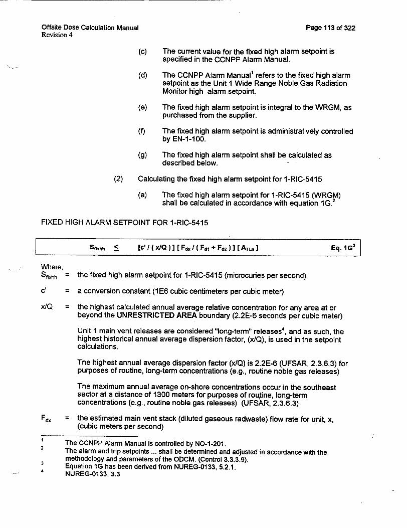
(a) The fixed high alarm setpoint for 1-RIC-5415 (WRGM) shall be calculated in accordance with equation 1G.2
FIXED HIGH ALARM SETPOINT FOR I-RIC-5415
Sfixhh < [c'I (xQ)] [FxI ( Fdl FFd2)] [ATL. ] Eq. IG 3
Where,
Sfrh = the fixed high alarm setpoint for 1-RIC-5415 (microcuries per second)
cl = a conversion constant (1 E6 cubic centimeters per cubic meter)
x/Q = the highest calculated annual average relative concentration for any area at or beyond the UNRESTRICTED AREA boundary (2.2E-6 seconds per cubic meter)
Unit I main vent releases are considered "long-term" releases 4, and as such, the highest historical annual average dispersion factor, (x/Q), is used in the setpoint calculations.
The highest annual average dispersion factor (x/Q) is 2.2E-6 (UFSAR, 2.3.6.3) for purposes of routine, long-term concentrations (e.g., routine noble gas releases)
The maximum annual average on-shore concentrations occur in the southeast sector at a distance of 1300 meters for purposes of routine, long-term concentrations (e.g., routine noble gas releases) (UFSAR, 2.3.6.3)
Fdx = the estimated main vent stack (diluted gaseous radwaste) flow rate for unit, x, (cubic meters per second)
1 The CCNPP Alarm Manual is controlled by NO-1-201. 2 The alarm and trip setpoints ... shall be determined and adjusted in accordance with the
methodology and parameters of the ODCM. (Control 3.3.3.9). 4 Equation 1G has been derived from NUREG-01 33, 5.2.1.
NUREG-0133, 3.3

Offsite Dose Calculation Manual Page 114 of 322 Revision 4
The estimated main vent stack flow rates for Unit 1 and Unit 2 are defined below.
Fdl = the estimated main vent stack flow rate for Unit I (cubic meters per second)
Since the main vent stack flow rate will vary depending on the configuration of air dampers and the input gas streams, nominal main vent stack flow rate is used to calculate the fixed high setpoint.
Use the nominal Unit 1 main vent stack flow rate listed on Attachment 7.
The main vent stack flow rate shall be determined, in accordance with approved procedures, at least once per 6 months L± 25%). The Test and Equipment Unit shall be responsible for performing this test. The results of the main vent flow rate test shall be evaluated to ensure the main vent flow rates used in the ODCM are an accurate reflection of the true main vent flow rates. The Radiological Effluent Technical Specifications (RETS) Program Manager is responsible for modifying the (main vent flow rates used in the) ODCM in the event the main vent flow rate for either Unit 1 or Unit 2 has increased to a value which is greater than the maximum discharge flow rates listed on Attachment 7.
Fd2 = the estimated main vent stack (diluted gaseous radwaste) flow rate for unit 2 (cubic meters per second)
Since the main vent stack flow rate will vary depending on the configuration of air dampers and the input gas streams, nominal main vent stack flow rate is used to calculate the fixed high alarm setpoint.
Use the nominal Unit 2 main vent stack flow rate listed on Attachment 7.
The main vent stack flow rate shall be determined, in accordance with approved procedures, at least once per 6 months L+ 25%). The Test and Equipment Unit shall be responsible for performing this test. The results of the main vent flow rate test shall be evaluated to ensure the main vent flow rates used in the ODCM are an accurate reflection of the true main vent flow rates. The RETS Program Manager is responsible for modifying the (main vent flow rates used in the) ODCM in the event the main vent flow rate for either Unit 1 or Unit 2 has increased to a value which is greater than the maximum discharge flow rates listed on Attachment 7.
ATLn = the sum of the total specific activities of all radionuclides found in TYPICAL GASEOUS RADWASTE RELEASES (microcuries/cm 3)
Calculate ATLn in accordance with equation 2G.

Offsite Dose Calculation Manual Page 115 of 322 Revision 4
SPECIFIC ACTIVITY CORRESPONDING TO THE SITE BOUNDARY LIMIT
S[( f)(ATL)]/ALt < LMpc Eq. 2G1
Where, fi = a fraction which represents the relative activity contribution of noble gas
radionuclide i to the total noble gas activity for TYPICAL GASEOUS EFFLUENTS (unitless)
This value may be obtained using the guidance provided on Attachment 5.
AILt = the specific activity limit for radionuclide, i, as obtained from 10 CFR 20, Appendix B,-Table II, Column 1 (microcudes/cm 3)
For all the DOMINANT RADIONUCLIDEs found in TYPICAL RADWASTE EFFLUENTS, use the value from 10 CFR 20, Appendix B, Table II, Column 1.
For each of the LESS DOMINANT RADIONUCLIDEs found in TYPICAL RADWASTE EFFLUENTS, use 2E-14 microcuries per milliliter as the value for AiLt (per 10 CFR 20, Appendix B, Note 2).
LMpC = the site MPC limit (MPCs) for UNRESTRICTED AREAs
The value chosen for LMpc in this equation is 2. The basis for this limit is 10 CFR 50.72.
It has been shown2 that, for the radionuclides present in TYPICAL GASEOUS EFFLUENTS from CCNPP, the 2 MPC limit is more restrictive than the limits of Control 3.11.2.1 (a).
It should be noted that by using "2" as the MPC limit (10 CFR 50.72), instead of using the limits of Control 3.11.2.1(a), a safety factor has been incorporated into equation 2G.
An alarm setpoint corresponding to 2 MPCs serves to initiate a determination of whether the "4-hour NRC notification" (specified in 10 CFR 50.72) is required.
(3) Documenting the fixed high alarm setpoint
(a) Whenever the fixed high alarm setpoint is calculated, the specific values chosen for eaqh of the variables shall be documented in accordance with EN-I-100.
This equation has been derived from 10 CFR 20, Appendix B, Table II, Note 1. 2 Addendum To Setpoint Calculations For WRGM Monitors 1-RIC-5415 and 2-RIC-5415, R.L.
Conatser, December 10, 1991.

Offsite Dose Calculation Manual Page 116 of 322 Revision 4
(4) Changing the fixed high alarm setpoint for 1-RIC-5415
(a) If the fixed high alarm setpoint calculated in accordance with equation 1G exceeds the maximum range of the monitor, the fixed high setpoint shall be adjusted to a value which falls within the normal operating range of the monitor.
(b) The fixed high alarm setpoint may be established at values lower than the maximum allowable setpoint, if desired.
(c) A setpoint change should be initiated whenever any of the parameters identified in the setpoint calculation equations (identified in this section of the ODCM) have changed.
(d) The fixed high alarm setpoint should not be changed unless one of the following occurs:
i) the relative activity1 of any radionuclide in TYPICAL GASEOUS EFFLUENTS has changed by greater than 10%, and the new radionuclide mixture yields a fixed setpoint which is 10% (or more) lower than the current fixed setpoint,
ii) the historical maximum annual average atmospheric dispersion factor has changed,
iii) the MPC limit at the SITE BOUNDARY, (LMPc) has changed,
iv) the Unit I or Unit 2 main vent stack flow rate has changed by greater than or equal to 10%2,
v) the values listed in 10 CFR 20, Table II, column 1 have changed,
vi) the radiation monitor has been recently calibrated, repaired, or otherwise altered, or
vii) the monitor is not conservative in its function (see "Functions of 1-RE-5416" earlier in this section).
(e) EN-1-100 contains the administrative controls associated with changing and approving fixed high alarm setpoint.
As determined in accordance with Attachment 5. 2 As determined by analysis of the TE-001 and ETP-87-16 test results.

Offsite Dose Calculation Manual Page 117 of 322 Revision 4
i) Fixed alert setpoint for 1-RIC-5415
(1) General information
(a) The fixed alert setpoint is considered to be a fixed setpoint. The fixed alert setpoint is not adjusted for each release.
(b) Whenever the fixed alert setpoint is exceeded, an alarm will be generated.
(c) The CCNPP Alarm Manual does not reference this setpoint.
(d) The fixed alert setpoint is integral to the WRGM, as purchased from the supplier.
(e) The current value for the fixed alert setpoint is specified in the CCNPP Setpoint File.
(f) The fixed alert setpoint is administratively controlled by EN-I-100.
(g) The fixed alert setpoint shall be calculated as described below'.
(2) Calculating the fixed alert setpoint for 1-RIC-5415
(a) The fixed alert setpoint for 1-RIC-5415 shall be calculated as described below:
FIXED ALERT SETPOINT FOR 1-RIC-5415
Sfixh f K[ Sfhh] Eq. 3G
Where,
Sr~xh = the fixed alert setpoint for 1-RIC-5415 (microcuries per second)
Sfrh = the fixed high alarm setpoint for 1-RIC-5415 (microcuries per second)
Ksf = a constant, actually a safety factor, which is the fraction of the fixed high setpoint (unitless).
The safety factor chosen shall be less than or equal to 1.00. This ensures the fixed alert setpoint is always less than or equal to the fixed high alarm setpoint.
A safety factor of 1.00 will yield a fixed alert setpoint which corresponds to the fixed high alarm setpoint.
The alarm and trip setpoints ... shall be determined and adjusted in accordance with the methodology and parameters of the ODCM. (Control 3.3.3.9).

Offsite Dose Calculation Manual Page 118 of 322 Revision 4
A safety factor of 0. 100 will yield a fixed alert setpoint which corresponds to onetenth the fixed high alarm setpoint.
It is recommended that a safety factor of 0.1 be used for calculating the fixed alert setpoint, however, other values-not to exceed 1.00-may be used as directed by the General Supervisor Chemistry.
The particular value selected for the safety factor is somewhat arbitrary, however a value less than 1.00 does provide plant personnel with adequate time to respond to changing plant conditions and to initiate corrective ACTIONs so as to minimize the possibility of violating either the 10 CFR 50.72 limit or the Control 3.3.3.9 limits. The use of the safety factor is consistent with ALARA philosophy that licensees should make every reasonable effort to maintain radiation exposures, and releases of radioactive materials in effluents to UNRESTRICTED AREAS, as low as is reasonably achievable.
The use of a "safety margin" is in accordance with the provisions of NUREG-0133 which states that "... the alarm and trip setpoints ... should correspond to a value(s) which represents a safe margin of assurance that the instantaneous gaseous release limit of Control 3.11.2.1(a) will not be exceeded." (per NUREG-0133, 5.1.1).
This safety margin will prevent minor fluctuations in the nominal plant vent stack flow rates, errors in monitor efficiencies, and other statistical aberrations from adversely impacting the calculated fixed alert setpoint.
(3) Documenting the fixed alert alarm setpoint
(a) Whenever the fixed alert alarm setpoint is calculated, the specific values chosen for each of the variables shall be documented in accordance with EN-1-100.
(4) Changing the fixed alert alarm setpoint for 1-RIC-5415
(a) A setpoint change should be initiated whenever any of the parameters identified in equation 3G have changed.
(b) The fixed alert setpoint should be changed whenever the fixed high setpoint is changed.
(c) The fixed alert setpoint should be changed if the value of the safety factor is changed.
(d) See EN-I-100 for a description of activities associated with setpoint changes and setpoint approvals.

Offsite Dose Calculation Manual Page 119 of 322 Revision 4
j) Adjustable alarm setpoint for 1-RIC-5415
(1) General information
(a) This setpoint is an adjustable setpoint. Whenever this monitor is satisfying the minimum channels operable requirement (per Control 3.3.3.9), the adjustable setpoint is calculated and adjusted prior to each release of a WGDT, each containment vent, and each containment purge discharged via the main vent.
(b) The adjustable setpoint is based on the specific activities of the radionuclides present in either the WGDT or the containment building, whichever is applicable. (The radionuclide concentrations are determined by radiochemical analysis in accordance with applicable CHEMISTRY SECTION procedures as required by Control 4.11.2.1.2).
(c) Whenever the adjustable setpoint is exceeded, the WGDT, PURGE, or vent discharge via the main vent will be manually suspended.
(d) Refer to the Alarm Manual for a full list of operator ACTIONs taken in response to this alarm.
(e) The adjustable setpoint corresponds to the maximum concentration of radionuclides anticipated or expected when discharging a WGDT, a containment vent, or a containment purge via the main vent. For containment purges during outages, system evolutions may cause containment atmosphere activity to increase above what is normally expected for short periods of time.
(f) The value for the adjustable setpoint is recorded on the gaseous release permit in accordance with applicable CHEMISTRY SECTION procedures.
(g) This alarm is not integral to the main vent radiation monitor, as purchased from the supplier.
(h) This alarm is generated by the plant computer which monitors output from 1/2-RIC-5415, and provides an alarm to plant operators wherý the 1/2-RIC-5415 adjustable setpoint has been exceeded.
(i) When this monitor is satisfying the minimum channels operable requirement (per Control 3.3.3.9), a value for the adjustable alarm setpoint shall be calculated prior to each release of a WGDT, each containment vent, and each containment purge as shown below.

Offsite Dose Calculation Manual Page 120 of 322 Revision 4
(2) Calculating the adjustable setpoint for 1/2-RIC-5415
(a) The adjustable alarm setpoint is based on the specific activity of the radionuclides in the undiluted gaseous waste (as determined by radiochemical analysis per Control 4.11.2.1.2), and the alarm setpoint is calculated as shown below.
ADJUSTABLE ALARM SETPOINT FOR 1/2-RIC-5415
Sdj < (Kf) (FdX) (c') {[(Fu I Fd) Y (A.) (el) J + Bkg} Eq. 29G 1
Sadj = the adjustable alarm setpoint for 1/2-RIC-5415 (microcuries per second)
KSf = a constant, actually a safety factor, which allows for fluctuation in radiation monitor response (unitless)
This safety factor helps ensure the release is not unnecessarily terminated due to (1) electronic anomalies which cause spurious monitor responses, (2) statistical fluctuations in disintegration rates, (3) statistical fluctuations in detector efficiencies, (4) errors associated with sample analysis, (5) errors associated with monitor calibrations2, and (6) anticipated short term variations in containment activity (applicable to containment purges only).
It is recommended that a safety factor of 10 for containment purge releases be used for calculating the adjustable setpoint. However, other values for purge releases - not to exceed 10 - may be used as directed by the General Supervisor Chemistry. A safety factor of 1.5 shall be used for all other gaseous releases.
The particular value selected for the safety factor is somewhat arbitrary, however a value less than or equal to 10 does provide plant personnel with adequate time to respond to changing plant conditions and to initiate corrective ACTIONs so as to minimize the possibility of violating either the 10 CFR 50.72 limit or the Control 3.3.3.9 limits.
The use of the safety factor is consistent with ALARA philosophy that licensees should make every reasonable effort to maintain radiation exposures, and releases of radioactive materials in effluents to UNRESTRICTED AREAS, as low as is reasonably achievable.
The use of a "safety margin" is in accordance with the provisions of NUREG-0133 which states that ".. . the alarm and trip setpoints... st~ould correspond to a value(s) which represents a safe margin of assurance that the instantaneous gaseous release limit of Control 3.11.2.1 (a) will not be exceeded." (per NUREG-0133, 5.1.1).
2 Equation 29G has been derived from NUREG-0133, Addendum, page AA-I. 2 The "analysis errors" and "calibration errors" refer to errors which are within established quality assurance and quality control limits.

Offsite Dose Calculation Manual Page 121 of 322 Revision 4
This safety margin will prevent minor fluctuations in the nominal plant vent stack flow rates, errors in monitor efficiencies, and other statistical aberrations from adversely impacting the calculated adjustable setpoint. Additionally for a special case of containment purges during outages, the safety factor allows for short term variations in activity created as a result of system evolutions in containment.
Fu = maximum undiluted radwaste flow rate (cubic meters per second)
Values of maximum undiluted radwaste flow rates for various waste streams are tabulated in Attachment 7.
FdX = the estimated main vent stack (diluted gaseous radwaste) flow rate for unit x (cubic meters per second)
Since the main vent stack flow rate will vary depending on the reactor unit, the configuration of air dampers, and the input gas streams, nominal main vent stack flow rate is used to calculate the adjustable setpoint.
Use the nominal main vent stack flow rate, for the appropriate unit, listed on Attachment 7.
The main vent stack flow rate shall be determined, in accordance with approved procedures, at least once per 6 months (± 25%). The Test and Equipment Unit shall be responsible for performing this test. The results of the main vent flow rate test shall be evaluated to ensure the main vent flow rates used in the ODCM are an accurate reflection of the true main vent flow rates. The RETS Program Manager is responsible for modifying the (main vent flow rates used in the) ODCM in the event the main vent flow rate for either Unit 1 or Unit 2 has increased to a value which is greater than the maximum discharge flow rates listed on Attachment 7.
Aiu = specific activity of radionuclide, i, in the undiluted waste stream, either the WGDT or the containment building (microcuries per cubic centimeter)
ei = absolute detector efficiency for nuclide, i (microcuries Xe-133 equivalent per microcuries nuclide i)
The detector efficiency for each radionuclide may be calculated from data collected during calibration of the radiation monitor.
Bkg = an approximation of the detector background (microcuries per cubic centimeter)
= a conversion constant (1 E6 cubic centimeters per cubic meter)C!

Revision 4
(3) Documenting the adjustable alarm setpoint for 1/2-RIC-5415
(a) Whenever the adjustable setpoint is calculated, the specific values chosen for each of the variables shall be documented in accordance with approved CHEMISTRY SECTION procedures (e.g., CP-604).
(4) Changing the adjustable alarm setpoint for 1/2-RIC-5415
(a) In all cases, the adjustable alarm setpoint shall be set to a value which is less than or equal to the fixed setpoint.
(b) If the adjustable alarm setpoint exceeds the maximum range of the monitor, the setpoint shall be adjusted to a value which falls within the normal operating range of the monitor.
(c) CHEMISTRY SECTION procedures (e.g., CP-604) contain administrative controls associated with calculating and approving an adjustable setpoint.
(d) Whenever this monitor is satisfying the minimum channels operable requirement (per Control 3.3.3.9 ) the calculated value for the adjustable setpoint shall be entered into the plant computer prior to each release of a WGDT, a containment vent, or a containment purge via the main vent.
k) Alert setpoint for 1-RIC-5415
(1) General information
(a) The alert setpoint is applicable to containment purges only.
(b) This setpoint is an alert setpoint. Whenever this monitor is satisfying the minimum channels operable requirement (per Control 3.3.3.9 ), the alert setpoint is calculated and adjusted prior to each containment purge discharged via the main vent.
(c) The alert setpoint is based on the specific activities of the radionuclides present in the containment building. (The radionuclide concentrations a~e determined by radiochemical analysis in accordance with applicable CHEMISTRY SECTION procedures as required by Control 4.11.2.1.2).
(d) Whenever the alert setpoint is exceeded the PURGE via the main vent may continue.
Offsite Dose Calculation Manual Page 122 of 322

Offsite Dose Calculation Manual Page 123 of 322 Revision 4
(e) The alert setpoint corresponds to a level of activity which indicates additional source term(s) may be present, and as a result, additional notifications and/or actions are required to identify the source and to accurately account for the activity discharged.
(f) The value for the alert setpoint is recorded on the gaseous release permit in accordance with applicable CHEMISTRY SECTION procedures.
(g) This alarm is not integral to the main vent radiation monitor, as purchased from the supplier.
(h) This alarm is generated by the plant computer which monitors output from 1/2-RIC-5415, and provides an to plant operators when the 1/2-RIC-5415 alert setpoint has been exceeded.
(i) When this monitor is satisfying the minimum channels operable requirement (per Control 3.3.3.9), a value for the alert setpoint shall be calculated prior to each containment purge via the main vent as shown below.
(2) Calculating the alert setpoint for 1/2-RIC-5415
(a) The alert setpoint is based on the specific activity of the radionuclides in the undiluted gaseous waste (as determined by radiochemical analysis per Control 4.11.2.1.2), and the setpoint is calculated as shown below.
ALERT SETPOINT FOR 1/2-RIC-5415
Sart < (1.50)(FdX)(C'l[lF l/Fdx, A(4 .)lel)]+Bkg} Eq. 29G'
Salert = the alert setpoint for 1/2-RIC-5415 (microcuries per second)
1.50 = a constant, actually a safety factor, which allows for fluctuation in radiation monitor response (unitless)
This safety factor helps ensure the release is not unnecessarily terminated due to (1) electronic anomalies which cause spurious monitor responses, (2) statistical fluctuations in disintegration rates, (3) statistical fluctuations in detector efficiencies, (4) errors associated with sample analysis, and (5) errors associated with monitor calibrations 2.
Equation 29G has been derived from NUREG-0133, Addendum, page AA-1. 2 The "analysis errors" and "calibration errors" refer to errors which are within established quality
assurance and quality control limits.

Offsite Dose Calculation Manual Page 124 of 322 Revision 4
The use of the safety factor is consistent with ALARA philosophy that licensees should make every reasonable effort to maintain radiation exposures, and releases of radioactive materials in effluents to UNRESTRICTED AREAS, as low as is reasonably achievable.
The use of a "safety margin" is in accordance with the provisions of NUREG-0133 which states that "... the alarm and trip setpoints ... should correspond to a value(s) which represents a safe margin of assurance that the instantaneous gaseous release limit of Control 3.11.2.1(a) will not be exceeded." (per NUREG-0133, 5.1.1).
This safety margin will prevent minor fluctuations in the nominal plant vent stack flow rates, errors in monitor efficiencies, and other statistical aberrations from adversely impacting the calculated alert setpoint.
Fu = maximum undiluted radwaste flow rate (cubic meters per second)
Values of maximum undiluted radwaste flow rates for various waste streams are tabulated in Attachment 7.
Fdx = the estimated main vent stack (diluted gaseous radwaste) flow rate for unit x (cubic meters per second)
Since the main vent stack flow rate will vary depending on the reactor unit, the configuration of air dampers, and the input gas streams, nominal main vent stack flow rate is used to calculate the alert setpoint.
Use the nominal main vent stack flow rate, for the appropriate unit, listed on Attachment 7.
The main vent stack flow rate shall be determined, in accordance with approved procedures, at least once per 6 months (+ 25%). The Test and Equipment Unit shall be responsible for performing this test. The results of the main vent flow rate test shall be evaluated to ensure the main vent flow rates used in the ODCM are an accurate reflection of the true main vent flow rates. The RETS Program Manager is responsible for modifying the (main vent flow rates used in the) ODCM in the event the main vent flow rate for either Unit 1 or Unit 2 has increased to a value which is greater than the maximum discharge flow rates listed on Attachment 7.
A.u = specific activity of radionuclide, i, in the containment building (microcuries per cubic centimeter)
e, = absolute detector efficiency for nuclide, i (microcuries Xe-133 equivalent per microcuries nuclide i)
The detector efficiency for each radionuclide may be calculated from data collected during calibration of the radiation monitor.
Bkg = an approximation of the detector background (microcuries per cubic centimeter)
c! = a conversion constant (1 E6 cubic centimeters per cubic meter)

Offsite Dose Calculation Manual Page 125 of 322 Revision 4
(3) Documenting the alert setpoint for 1/2-RIC-5415
(a) Whenever the alert setpoint is calculated, the specific values chosen for each of the variables shall be documented in accordance with approved CHEMISTRY SECTION procedures (e.g., CP-604).
(4) Changing the alert setpoint for 1/2-RIC-5415
(a) In all cases, the alert setpoint shall be set to a value which is less than or equal to the fixed setpoint.
(b) If the alert setpoint exceeds the maximum range of the monitor, the setpoint shall be adjusted to a value which falls within the normal operating range of the monitor.
(c) CHEMISTRY SECTION procedures (e.g., CP-604) contain administrative controls associated with calculating and approving an alert setpoint.
(d) Whenever this monitor is satisfying the minimum channels operable requirement (per Control 3.3.3.9) the calculated value for the alert setpoint shall be entered into the plant computer prior to each containment purge via the main vent.
2. Wide Range Gas Monitor (2-RE-5416)
a) all information related to 1-RE-5416 is applicable to the Unit 2 WRGM with the following exceptions(s)
b) Monitors equivalent to 2-RE-5416
(1) 2-RE-5415 [the "Westinghouse Plant Vent Stack Monitor"] has the capability of providing the measurement and alarm functions of 2-RE-5416 during times when 2-RE-5416 is declared inoperable
(2) 2-RE-5415 provides redundant monitoring [for 2-RE-5416] at the low end of the concentration ranges (UFSAR 11.2.3.2.12)
3. Westinghouse Plant Vent Stack Monitor (1-RE-5415)
a) The Westinghouse Plant Vent Stack Monitor contains 2 radiation elements
(1) 1-RE-5414
(a) particulate detector
(b) off-line scintillation detector
(c) analog output

Offsite Dose Calculation Manual Page 126 of 322 Revision 4
(d) supplies signals to radiation indicator 1/2-RI-5414
(e) values displayed by 1/2-RI-5414 are in units of counts per minute
(f) the detector manufacturer is Westinghouse
(2) 1-RE-5415
(a) noble gas detector
(b) off-line GM Tube
(c) analog output
(d) supplies signals to radiation indicator 1/2-RI-5415
(e) values displayed by 1/2-RI-5415 are in units of counts per minute
(f) the detector manufacturer is Westinghouse
b) Functions of 1-RE-5414
(1) The functions of 1-RE-5414 are mentioned here only as a basis for excluding this radiation element from the setpoint controls of Control 3.3.3.9.
(2) This monitor (the particulate monitor) was retired in place.
c) Functions of 1-RE-5415 1
(1) continuously measure the activity (cpm) of noble gases emanating from the Unit 1 main vent stack (Control 4.11.2.1.2, Table 4.11-2)
(2) continuously indicate (via 1-RI-5415) the activity (cpm) of noble gases emanating from the Unit 1 main vent stack (Control 4.11.2.1.2, Table 4.11-2)
(3) alarm (via 1-RI-5415) prior to exceeding the site-boundary, noblegas, total-body-dose-rate limit of 500 mr/yr (per Control 3.11.2.1.a)
(4) alarm (via 1-RIC-5415) prior to exceeding the site-boundary, noble-gas, skin-dose-rate limit of 3000 mr/yr (per Control 3.11.2.1.a)
This (radiation element) monitors noble gases. Other radiation elements monitor particulates in this waste stream.

Offsite Dose Calculation Manual Page 127 of 322 Revision 4
d) OPERABILITY of 1-RE-5415
(1) This monitor shall be operable (or have OPERABILITY) when it is capable of performing its specified function(s).
(2) The functions of 1-RE-5415 are listed in section (c) above.
e) Monitors equivalent to 1-RE-5415
(1) The Wide Range Gas Monitor (i.e., 1-RE-5416) has the capability of providing the measurement and alarm functions of 1-RE-5415 during times when 1-RE-5415 is declared inoperable.
(2) 1-RE-5415 provides redundant monitoring [for 1-RE-5416] at the low end of the concentration ranges (UFSAR 11.2.3.2.12).
(3) In the event 1-RE-5415 is inoperable or otherwise unavailable, 1-RE-5416 may fulfill the measuring, indicating, and alarming functions normally provided by 1-RE-5415.
(4) The absence of a radiation element dedicated to measuring the particulate activity in the Wide Range Gas Monitor does not preclude the use of 1-RE-5416 as a backup for 1-RE-5415. This is mentioned only as a basis for excluding 1/2-RE-5414 from the setpoint controls of Control 3.3.3.9 (see "Functions of 1-RE-5414" earlier in this section).
f) Radiological effluent controls for 1-RE-5415
(1) Control 3.3.3.9 states that releases via the plant vent stack may continue if any one of the following three conditions are satisfied
(a) 1-RE-5415 is operable AND the alarm and trip setpoint(s) for 1-RI-5415 are set to ensure the annual dose rates due to noble gases at the SITE BOUNDARY are less than 500 mr/yr to the total body and are less than 3000 mr/yr to the skin (per Control 3.11.2.1.a), or
(b) an "equivalent monitor" (see section (e) above) is operable AND the alarm and trip setpoint(s) for the "equivalent monitor" are set to ensure annual dose rates due to noble gases at the SITE BOUNDARY are less than 500 mr/yr to the total body and are less than 3000 mr/yr to the skin (per Control 3.11.2.1\a), or
(c) grab samples are obtained and analyzed for gross activity at least once per 24 hours in accordance with Controls 3.11.2.1.a, 4.11.2.1.1, and 4.11.2.1.2 (per Control 4.3.3.9, Table 3.3-12, ACTION 37).

Offsite Dose Calculation Manual Page 128 of 322 Revision 4
(2) Control 3.11.2.1.b (i.e., dose rates due to iodines and particulates at the SITE BOUNDARY) is not applicable to noble gas detector or to the setpoints related to the noble gas detector 1-RE-5415. As a result, the 1500 my/yr organ dose limit is not included as a radiological effluent control in this section of the ODCM.
g) Surveillances for 1-RE-5415
(1) Control 4.3.3.9 requires demonstrating the OPERABILITY of 1RE-5415 by satisfying the checks, calibrations, and tests listed below:
(a) CHANNEL CHECK within the past 24 hours
(b) SOURCE CHECK within the past 31 days
(c) CHANNEL CALIBRATION within the past 18 months
(d) CHANNEL FUNCTIONAL TEST within the past 6 six months
h) Setpoints for 1-RI-5415
(1) Requirements and commitments
(a) The alarm and trip setpoints ... shall be determined and adjusted in accordance with the methodology and parameters of the ODCM. (Control 3.3.3.9)
(b) The method for calculating fixed or adjustable setpoints shall be provided in the ODCM. (NUREG-0133, 5.1.1)
(2) There are four alarms associated with, or otherwise related to,
1-RE-5415.
(a) 1-RI-5415 fixed high radiation alarm setpoint
(b) 1-RI-5415 adjustable plant computer high radiation alarm setpoint
(c) 1-RI-5415 low radiation alarm setpoint
(d) 1-RI-5415 adjustable plant computer alert setpoint.
(3) In order to simplify the setpoint terminology, eliminate ambiguity, and minimize the possibility of misinterpretation, the ODCM will refer to these setpoints as follows
(a) The 1-RI-5415 fixed high radiation alarm setpoint will be referred to as the fixed setpoint.
(b) The 1-RI-5415 adjustable plant computer high radiation alarm setpoint will be referred to as the adjustable setpoint.

Offsite Dose Calculation Manual Page 129 of 322 Revision 4
(c) The 1-RI-5415 low radiation alarm setpoint will be referred to as the low setpoint.
(d) The 1-RI-5415 adjustable plant computer alert setpoint will
be referred to as the alert setpoint.
(4) Each of these alarm setpoints are described below.
i) The fixed setpoint for 1-RI-5415
(1) General information
(a) This setpoint is considered to be a fixed setpoint. The fixed setpoint is not adjusted for each release.
(b) Whenever the fixed setpoint is exceeded, an alarm will be generated.
(c) The current value for the fixed setpoint is specified in the CCNPP Alarm Manual.
(d) The CCNPP Alarm Manual refers to this setpoint as the 1RI-5415 High Alarm Setpoint.
(e) The fixed setpoint is integral to the Main Vent (Westinghouse) RMS as purchased from the supplier.
(f) The fixed setpoint is administratively controlled by EN-1100.
(g) The fixed setpoint shall be calculated as described below1.
(2) Calculating the fixed setpoint for 1-RI-5415
(a) The fixed high radiation alarm setpoint for 1-RI-5415 (plant vent stack monitor) shall be calculated in accordance with equation 4G.
THE FIXED HIGH ALARM SETPOINT FOR 1-RI-5415
Sx _ Kf [(x/Q) (Fdl+ Fd 2 ) ] (e,)(A)] Eq. 4G2
Sftx = the fixed radiation alarm setpoint for 1-RI-5415 (counts per minute)
Ksf = a constant, actually a safety factor, which is the ratio of the CCNPP activity limit to the MPC limit, LMpc, used in equation 2G (unitless)
The alarm and trip setpoints ... shall be determined and adjusted in accordance with the
2 methodology and parameters of the ODCM. (Control 3.3.3.9). Equation 4G has been derived from NUREG-0133, 5.2.1, (the 500 mr/yr equation).

Offsite Dose Calculation Manual Page 130 of 322 Revision 4
The safety factor chosen shall be less than or equal to 1.00. This ensures the fixed setpoint is always less than or equal to the MPC limit, LMpc, used in equation 2G.
A safety factor of 1.00 will yield a fixed setpoint which corresponds to the MPC limit, LMpc, in equation 2G.
A safety factor of 0.500 will yield a fixed high setpoint which corresponds to onehalf the MPC limit, LMPc, in equation 2G.
It is recommended that a safety factor of 1.0 be used for calculating the fixed setpoint, however, other values--not to exceed 1.00-may be used as directed by the General Supervisor Chemistry.
The particular value selected for the safety factor is somewhat arbitrary, however a safety factor does provide plant personnel with adequate time to respond to changing plant conditions and to initiate corrective ACTIONs so as to minimize the possibility of violating either the 10 CFR 50.72 limit or the Control 3.3.3.9 limits.
The use of a safety factor is consistent with the ALARA philosophy that licensees should make every reasonable effort to maintain radiation exposures, and releases of radioactive materials in effluents to UNRESTRICTED AREAS, as low as is reasonably achievable.
The use of a "safety margin" is in accordance with the provisions of NUREG-0133, section 5.1.1, which states that "... the alarm and trip setpoints ... should correspond to a value(s) which represents a safe margin of assurance that the instantaneous gaseous release limit of Control 3.11.2.1 (a) will not be exceeded."
This safety margin will prevent minor fluctuations in the nominal plant vent stack flow rates, errors in detector efficiencies, and other statistical aberrations from adversely impacting the calculated fixed setpoint.
x/Q = the highest calculated annual average relative concentration for any area at or beyond the UNRESTRICTED AREA boundary (2.2E-6 seconds per cubic meter)
Unit I and Unit 2 main vent releases are considered "long-term" releases1 , and as such, the highest historical annual average dispersion factor, (x/Q), is used in the setpoint calculations.
The highest annual average dispersion factor (x/Q) is 2.2E-6 (UFSAR, 2.3.6.3) for purposes of routine, long-term concentrations (e.g., routine noble gas releases).
The maximum annual average on-shore concentrations occur in the southeast sector at a distance of 1300 meters for purposes of rotLtine, long-term concentrations (e.g., routine noble gas releases) (UFSAR, 2.3.6.3).
Fdl = the estimated main vent stack flow rate for Unit I (cubic meters per second)
Since the main vent stack flow rate will vary depending on the configuration of air dampers and the input gas streams, nominal main vent stack flow rate is used to calculate the fixed high setpoint.
NUREG-01 33, 3.31

Offsite Dose Calculation Manual Page 131 of 322 Revision 4
Use the nominal Unit 1 main vent stack flow rate listed on Attachment 7.
The main vent stack flow rate shall be determined, in accordance with approved procedures, at least once per 6 months (. 25%). The Test and Equipment Unit shall be responsible for performing this test. The results of the main vent flow rate test shall be evaluated to ensure the main vent flow rates used in the ODCM are an accurate reflection of the true main vent flow rates. The RETS Program Manager is responsible for modifying the (main vent flow rates used in the) ODCM in the event the main vent flow rate for either Unit 1 or Unit 2 has increased to a value which is greater than the maximum discharge flow rates listed on Attachment 7.
Fd2 = the estimated main vent stack flow rate for unit 2 (cubic meters per second)
Since the main vent stack flow rate will vary depending on the configuration of air dampers and the input gas streams, nominal main vent stack flow rate is used to calculate the fixed high setpoint.
Use the nominal Unit 2 main vent stack flow rate listed on Attachment 7.
The main vent stack flow rate shall be determined, in accordance with approved procedures, at least once per 6 months (+ 25%). The Test and Equipment Unit shall be responsible for performing this test. The results of the main vent flow rate test shall be evaluated to ensure the main vent flow rates used in the ODCM are an accurate reflection of the true main vent flow rates. The RETS Program Manager is responsible for modifying the (main vent flow rates used in the) ODCM in the event the main vent flow rate for either Unit I or Unit 2 has increased to a value which is greater than the maximum discharge flow rates listed on Attachment 7.
e = absolute detector efficiency for nuclide, i (cpm/microcuries per milliliter)
The detector efficiency for each radionuclide may be calculated from data collected during calibration of the radiation monitor.
AiLn = the specific activities of radionuclide, i, found in TYPICAL GASEOUS RADWASTE RELEASES (calculated in accordance with 10 CFR 20, Appendix B, Table II, Note 1 as described below; microcuries per milliliter)
Calculate AlLn in accordance with equation 5G.
SPECIFIC ACTIVITY LIMIT FOR NUCLIDE I IN A RADIONUCLIDE MIXTURE
AILn - (f)(ATLn) Eq. 5G
= a fraction which represents the relative activity contribution of noble gas radionuclide i to the total noble gas activity for TYPICAL GASEOUS EFFLUENTS (unitless)
This value may be obtained using the guidance provided on Attachment 5.
ATLn = the sum of the total specific activities of all noble gas radionuclides found in TYPICAL GASEOUS RADWASTE RELEASES (microcuries/cm 3)

Offsite Dose Calculation Manual Revision 4
Page 132 of 322
Calculate ATLn in accordance with equation 2G.
SPECIFIC ACTIVITY CORRESPONDING TO THE SITE BOUNDARY LIMIT
Y •"[ ( fl) (ATLn ) ]/AI~t _< Lmpc Eq. 2G1
LMpc = the MPC limit
The value chosen for Lipc in this equation is 2. The basis for this limit is 10 CFR 50.72.
It has been shown2 that, for the radionuclides present in TYPICAL GASEOUS EFFLUENTS from CCNPP, the 2 MPC limit is more restrictive than the limits of Control 3.3.3.9.
It should be noted that by using "2" as the MPC limit (10 CFR 50.72), instead of using the limits of Control 3.11.2.1(a), a safety factor has been incorporated into equation 2G.
The use of 2 MPCs as a safety margin is consistent with the provisions of NUREG0133, section 5.1.1, which states that, "... in all cases, conservative assumptions may be necessary in establishing these setpoints to account for system variables, .. the variability in release flow, ... and the time lag between alarm and final isolation of radioactive effluents."
An alarm setpoint corresponding to 2 MPCs serves to initiate a determination of whether the "4-hour NRC notification" (specified in 10 CFR 50.72) is required.
The use of a limiting specific activity equivalent to 2 MPCs is consistent with the provisions of 10 CFR 20.1302.
AiLt = the specific activity limit for radionuclide, i, as obtained from 10 CFR 20, Appendix B, Table II, Column 1 (microcuries/cm 3)
For all the DOMINANT RADIONUCLIDEs found in TYPICAL RADWASTE EFFLUENTS, use the value from 10 CFR 20, Appendix B, Table II, Column 1.
For each of the LESS DOMINANT RADIONUCLIDEs found in TYPICAL RADWASTE EFFLUENTS, use 2E-14 microcuries per milliliter as the value for AiLt (per 10 CFR 20, Appendix B, Note 2).
1 Equation 2G has been derived from 10 CFR 20, Appendix B, Table II, Note 1. 2 Addendum To Setpoint Calculations For WRGM Monitors 1-RIC-5415 and 2-RIC-5415, R.L.
Conatser, December 10, 1991.

Offsite Dose Calculation Manual Page 133 of 322 Revision 4
(3) The low alarm setpoint for 1-RI-5415
(a) The ODCM does not address the calculations associated with the low alarm setpoint.
(b) The low alarm setpoint is specified in the CCNPP Alarm Manual.
(c) The low alarm setpoint may be used to determine OPERABILITY of this monitor (in accordance with the provisions of Control 4.3.3.9, Table 4.3-11, Note 2).
(4) Adjusting the fixed setpoint for 1-RI-5415
(a) If the fixed setpoint calculated in accordance with equation 4G exceeds the maximum range of the monitor, the fixed setpoint shall be adjusted to a value which falls within the normal operating range of the monitor.
(b) The fixed setpoint may be established at values lower than the maximum allowable setpoint, if desired.
(c) A setpoint change should be initiated whenever any of the parameters identified in equation 4G have changed.
(d) The fixed setpoint should not be changed unless one of the following occurs:
i) the relative activity1 of any radionuclide in TYPICAL GASEOUS EFFLUENTS has changed by greater than 10%, and the new radionuclide mixture yields a fixed setpoint which is 10% (or more) lower than the current fixed setpoint,
ii) the historical maximum annual average atmospheric dispersion factor has changed,
iii) the MPC limit at the SITE BOUNDARY, (presently 2 MPCs) has changed,
iv) the estimated Unit 1 main vent stack flow rate or Unit 2 main vent stack flow rate has changed by greater than or equal to 10%2,
v) the values listed in 10)CFR 20, Table 11, column 1 have changed,
vi) the radiation monitor has been recently calibrated, repaired, or otherwise altered, or
As determined in accordance with Attachment 5. 2 As determined by analysis of the TE-001 and ETP-87-16 test results.

Offsite Dose Calculation Manual Page 134 of 322 Revision 4
vii) the monitor is not conservative in its function (see section "Functions of 1/2-RE-5415" earlier in this section).
(e) EN-1-100 contains the administrative controls associated with changing and approving fixed alarm setpoint.
j) Adjustable alarm setpoint for 1/2-RI-5415
(1) General information
(a) This setpoint is an adjustable setpoint. Whenever this monitor is satisfying the minimum channels operable requirement (per Control 3.3.3.9), the adjustable setpoint is calculated and adjusted prior to each release of a WGDT, each containment vent, and each containment purge discharged via the main vent.
(b) The adjustable setpoint is based on the specific activities of the radionuclides present in either the WGDT or the containment building, whichever is applicable. (The radionuclide concentrations are determined by radiochemical analysis in accordance with applicable CHEMISTRY SECTION procedures as required by Control 4.11.2.1.2).
(c) Whenever the adjustable setpoint is exceeded, the WGDT, PURGE, or vent discharge via the main vent will be manually suspended.
(d) Refer to the Alarm Manual for a full list of operator ACTIONs taken in response to this alarm.
(e) The adjustable setpoint corresponds to the maximum concentration of radionuclides anticipated or expected when discharging a WGDT, a containment vent, or a containment purge via the main vent. For containment purges during outages, system evolutions may cause containment atmosphere activity to increase above what is normally expected for short periods of time.
(f) The value for the adjustable setpoint is recorded on the gaseous release permit in accordance with applicable CHEMISTRY SECTION procedures.
(g) This alarm is not integral to the main vent radiation monitor, as purchased from the supplier.

Offsite Dose Calculation Manual Page 135 of 322 Revision 4
(h) This alarm is generated by the plant computer which monitors output from 1/2-RI-5415, and provides an alarm to plant operators when the 1/2-RI-5415 adjustable setpoint has been exceeded.
(i) When this monitor is satisfying the minimum channels operable requirement (per Control 3.3.3.9), a value for the adjustable alarm setpoint shall be calculated prior to each release of a WGDT, each containment vent, and each containment purge as shown below.
(2) Calculating the adjustable setpoint for 1/2-RI-5415
(a) The adjustable alarm setpoint is based on the specific activity of the radionuclides in the undiluted gaseous waste (as determined by radiochemical analysis per Control 4.11.2.1.2), and the alarm setpoint is calculated as shown below.
ADJUSTABLE ALARM SETPOINT FOR 1/2-RI-5415
Sadj -< (Kf)l(F/Fdx)[Z(AIU)(e1) + Bkg] Eq.27G'
Sadj = the adjustable alarm setpoint for 1/2-RI-5415 (cpm)
Kf = a constant, actually a safety factor, which allows for fluctuation in radiation monitor response (unitless)
This safety factor helps ensure the release is not unnecessarily terminated due to (1) electronic anomalies which cause spurious monitor responses, (2) statistical fluctuations in disintegration rates, (3) statistical fluctuations in detector efficiencies, (4) errors associated with sample analysis, (5) errors associated with monitor calibrations2 , and (6) anticipated short term variations in activity (this applicable to containment purges only).
It is recommended that a safety factor of 10 for containment purge releases be used for calculating the adjustable setpoint. However, other values for purge releases - not to exceed 10 - may be used as directed by the General Supervisor Chemistry. A safety factor of 1.5 shall be used for all other gaseous releases.
The particular value selected for the safety factor is somewhat arbitrary, however a value less than or equal to 10 does provide plant personpnel with adequate time to respond to changing plant conditions and to initiate corrective ACTIONs so as to minimize the possibility of violating either the 10 CFR 50.72 limit or the Control 3.3.3.9 limits.
2 Equation 27G has been derived from NUREG-0133, Addendum, page AA-1. 2 The "analysis errors" and "calibration errors" refer to errors which are within established quality assurance and quality control limits.

Offsite Dose Calculation Manual Page 136 of 322 Revision 4
The use of the safety factor is consistent with ALARA philosophy that licensees should make every reasonable effort to maintain radiation exposures, and releases of radioactive materials in effluents to UNRESTRICTED AREAS, as low as is reasonably achievable.
The use of a "safety margin" is in accordance with the provisions of NUREG-0133 which states that "... the alarm and trip setpoints ... should correspond to a value(s) which represents a safe margin of assurance that the instantaneous gaseous release limit of Control 3.11.2.1(a) will not be exceeded." (per NUREG-0133, 5.1.1).
This safety margin will prevent minor fluctuations in the nominal plant vent stack flow rates, errors in monitor efficiencies, and other statistical aberrations from adversely impacting the calculated adjustable setpoint. Additionally for a special case of containment purges during outages, the safety factor allows for short term variations in activity created as a result of system evolutions in containment.
Fu = maximum undiluted radwaste flow rate (cubic meters per second)
Values of maximum undiluted radwaste flow rates for various waste streams are tabulated in Attachment 7.
Fdx = the estimated main vent stack (diluted gaseous radwaste) flow rate for unit x (cubic meters per second)
Since the main vent stack flow rate will vary depending on the reactor unit, the configuration of air dampers, and the input gas streams, nominal main vent stack flow rate is used to calculate the adjustable setpoint.
Use the nominal main vent stack flow rate, for the appropriate unit, listed on Attachment 7.
The main vent stack flow rate shall be determined, in accordance with approved procedures, at least once per 6 months (L 25%). The Test and Equipment Unit shall be responsible for performing this test. The results of the main vent flow rate test shall be evaluated to ensure the main vent flow rates used in the ODCM are an accurate reflection of the true main vent flow rates. The RETS Program Manager is responsible for modifying the (main vent flow rates used in the) ODCM in the event the main vent flow rate for either Unit 1 or Unit 2 has increased to a value which is greater than the maximum discharge flow rates listed on Attachment 7.
Aiu = specific activity of radionuclide, i, in the undiluted waste stream, either the WGDT or containment building as applicable (microcuries per milliliter)
ei = absolute detector efficiency for nuclide, i (cpm/microcu~es per milliliter)
The detector efficiency for each radionuclide may be calculated from data collected during calibration of the radiation monitor.
= an approximation of the detector background (cpm)Bkg

Offsite Dose Calculation Manual Page 137 of 322 Revision 4
(3) Documenting the adjustable alarm setpoint for 1/2-RI-5415
(a) Whenever the adjustable setpoint is calculated, the specific values chosen for each of the variables shall be documented in accordance with approved CHEMISTRY SECTION procedures (e.g., CP-604).
(4) Changing the adjustable alarm setpoint for 1/2-RI-5415
(a) In all cases, the adjustable alarm setpoint shall be set to a value which is less than or equal to the fixed setpoint.
(b) If the adjustable alarm setpoint exceeds the maximum range of the monitor, the setpoint shall be adjusted to a value which falls within the normal operating range of the monitor.
(c) CHEMISTRY SECTION procedures (e.g., CP-604) contain administrative controls associated with calculating and approving an adjustable setpoint.
(d) Whenever this monitor is satisfying the minimum channels operable requirement (per Control 3.3.3.9 ) the calculated value for the adjustable setpoint shall be entered into the plant computer prior to each release of a WGDT, a containment vent, or a containment purge via the main vent.
k) Alert setpoint for 1/2-RI-5415
(1) General information
(a) The alert setpoint is applicable to containment purges only.
(b) This setpoint is an alert setpoint. Whenever this monitor is satisfying the minimum channels operable requirement (per Control 3.3.3.9), the alert setpoint is calculated and adjusted prior to each containment purge discharged via the main vent.
(c) The alert setpoint is based on the specific activities of the radionuclides present in the containment building. (The radionuclide concentrations aie determined by radiochemical analysis in accordance with applicable CHEMISTRY SECTION procedures as required by Control 4.11.2.1.2).
(e) Whenever the alert setpoint is exceeded, the PURGE via the main vent may continue.

Offsite Dose Calculation Manual Page 138 of 322 Revision 4
(f) The alert setpoint corresponds to a level of activity which indicates additional source term(s) may be present, and as a result, additional notifications and/or actions are required to identify the source and to accurately account for the activity discharged.
(g) The value for the alert setpoint is recorded on the gaseous release permit in accordance with applicable CHEMISTRY SECTION procedures.
(h) This alarm is not integral to the main vent radiation monitor, as purchased from the supplier.
(i) This alarm is generated by the plant computer which monitors output from 1/2-RI-5415, and provides an alarm to plant operators when the 1/2-RI-5415 alert setpoint has been exceeded.
(j) When this monitor is satisfying the minimum channels operable requirement (per Control 3.3.3.9), a value for the alert setpoint shall be calculated prior to each containment purge as shown below.
(2) Calculating the alert setpoint for 1/2-RI-5415
(a) The alert setpoint is based on the specific activity of the radionuclides in the undiluted gaseous waste (as determined by radiochemical analysis per Control 4.11.2.1.2), and the setpoint is calculated as shown below.
ALERT SETPOINT FOR 1/2-RI-5415
SSae.t _< 1.50 ( F, / Fdx) [I (Au ) (ei) + Bkg Eq. 27G'
Salert = the alert setpoint for 1/2-RI-5415 (cpm)
1.50 = a constant, actually a safety factor, which allows for fluctuation in radiation monitor response (unitless).
This safety factor helps ensure the release is not unnecessarily terminated due to (1) electronic anomalies which cause spurious monitor responses, (2) statistical fluctuations in disintegration rates, (3) statistical fluctuations in detector efficiencies, (4) errors associated with sample analysis, and (5) errors associated with monitor calibrations.2
Equation 27G has been derived from NUREG-01 33, Addendum, page AA-1. 2 The "analysis errors" and "calibration errors" refer to errors which are within established quality
assurance and quality control limits.

Offsite Dose Calculation Manual Page 139 of 322 Revision 4
The use of the safety factor is consistent with ALARA philosophy that licensees should make every reasonable effort to maintain radiation exposures, and releases of radioactive materials in effluents to UNRESTRICTED AREAS, as low as is reasonably achievable.
The use of a "safety margin" is in accordance with the provisions of NUREG-0133 which states that "... the alarm and trip setpoints ... should correspond to a value(s) which represents a safe margin of assurance that the instantaneous gaseous release limit of Control 3.11.2.1(a) will not be exceeded." (per NUREG-0133, 5.1.1).
This safety margin will prevent minor fluctuations in the nominal plant vent stack flow rates, errors in monitor efficiencies, and other statistical aberrations from adversely impacting the calculated alert setpoint.
Fu = maximum undiluted radwaste flow rate (cubic meters per second)
Values of maximum undiluted radwaste flow rates for various waste streams are tabulated in Attachment 7.
Fdx = the estimated main vent stack (diluted gaseous radwaste) flow rate for unit x (cubic meters per second)
Since the main vent stack flow rate will vary depending on the reactor unit, the configuration of air dampers, and the input gas streams, nominal main vent stack flow rate is used to calculate the alert setpoint.
Use the nominal main vent stack flow rate, for the appropriate unit, listed on Attachment 7.
The main vent stack flow rate shall be determined, in accordance with approved procedures, at least once per 6 months (+ 25%). The Test and Equipment Unit shall be responsible for performing this test. The results of the main vent flow rate test shall be evaluated to ensure the main vent flow rates used in the ODCM are an accurate reflection of the true main vent flow rates. The RETS Program Manager is responsible for modifying the (main vent flow rates used in the) ODCM in the event the main vent flow rate for either Unit 1 or Unit 2 has increased to a value which is greater than the maximum discharge flow rates listed on Attachment 7.
Aiu = specific activity of radionuclide, i, in the containment building (microcuries per milliliter)
ej = absolute detector efficiency for nuclide, i (cpm/microcuries per milliliter)
The detector efficiency for each radionuclide may be calculated from data collected during calibration of the radiation monitor.
= an approximation of the detector background (cpm)Bkg

Offsite Dose Calculation Manual Page 140 of 322 Revision 4
(3) Documenting the alert setpoint for 1/2-RI-5415
(a) Whenever the alert setpoint is calculated, the specific values chosen for each of the variables shall be documented in accordance with approved CHEMISTRY SECTION procedures (e.g., CP-604).
(4) Changing the alert setpoint for 1/2-RI-5415
(a) In all cases, the alert setpoint shall be set to a value which is less than or equal to the fixed setpoint.
(b) If the alert setpoint exceeds the maximum range of the monitor, the setpoint shall be adjusted to a value which falls within the normal operating range of the monitor.
(c) CHEMISTRY SECTION procedures (e.g., CP-604) contain administrative controls associated with calculating and approving an alert setpoint.
(d) Whenever this monitor is satisfying the minimum channels operable requirement ( per Control 3.3.3.9 ) the calculated value for the alert setpoint shall be entered into the plant computer prior to each containment purge via the main vent.
1) The low alarm setpoint for 1/2-RI-5415
(1) This alarm is integral to the main vent monitor, as purchased from the supplier.
(2) The current value for the low alarm setpoint is specified in the CCNPP Alarm Manual.
(3) The low alarm setpoint may be used to determine the OPERABILITY of this monitor (per Control 4.3.3.9, CHANNEL FUNCTIONAL TEST).
(4) The alarm generated by the low alarm setpoint may be used to terminate a release in the event 1/2-RI-5415 fails (i.e., downscale failure or circuit failure) in accordance with Control 4.3.3.9.
(5) The low alarm setpoint calculations are not described in the ODCM.
(6) Changes to the low alarm setpoint are controlled by EN-1-100.
4. Westinghouse Plant Vent Stack Monitor (2-RE-5415)
a) All information related to 1-RE-5415 is applicable to the Unit 2 plant vent stack monitor with the following exception(s):

Offsite Dose Calculation Manual Revision 4
Page 141 of 322
b) Monitors equivalent to 2-RE-5415
(1) 2-RE-5416 [the "WRNGM'] has the capability of providing the measurement and alarm functions of 2-RE-5415 during times when 2-RE-5415 is declared inoperable.
(2) 2-RE-5415 provides redundant monitoring [for 2-RE-5416] at the low end of the concentration ranges (UFSAR 11.2.3.2.12).
5. Gaseous Radwaste Treatment System Radiation Monitor (0-RE-2191)
a) General description
(1) The GASEOUS RADWASTE TREATMENT SYSTEM Radiation Monitor (Waste Gas Decay Tank Radiation Monitor) contains 1 radiation element.
(2) It is a noble gas detector.
(3) The detector is an in-line GM tube (UFSAR, Table 11-10).
(4) The radiation element is designated O-RE-2191.
(5) The radiation indicators designated 0-RI-2191.
(6) The units for the radiation indicator are counts per minute.
(7) The monitor was manufactured by Westinghouse.
b) Functions of 0-RE-2191
(1) continuously measure the release rate of noble gases emanating from the waste gas decay tank discharge header (Control 4.11.2.1.2, Table 4.11-2)
(2) continuously indicate (via 0-RI-2191) the activity (cpm) of noble gases emanating from the waste gas decay tank discharge header (Control 3.3.3.9 OPERABILITY requirement)
(3) alarm (via 1-RI-2191) prior to exceeding the site-boundary, noblegas, total-body-dose-rate limit of 500 mr/yr (per Control 3.11.2.1.a)
(4) alarm (via 1-RI-2191) prior to exceeding the site-boundary, noblegas, skin-dose-rate limit of 3000 mr/yI (per Control 3.11.2.1 .a)
c) OPERABILITY of 0-RE-2191
(1) This monitor shall be operable (or have OPERABILITY) when it is capable of performing its specified function(s).
(2) For more information on the function(s) of this monitor, see "Functions of O-RE-2191" elsewhere in this section of the ODCM.

Offsite Dose Calculation Manual Page 142 of 322 Revision 4
d) Monitors equivalent to O-RE-2191
(1) There are no equivalent monitors associated with O-RE-2191 since there are no other radiation monitors permanently installed in the waste gas discharge header, however, Control 3.3.3.9 defines the plant vent stack monitor as a "BACKUP MONITOR."
(2) O-RE-2191 is designated the PRIMARY MONITOR for measuring noble gas activity released via the GASEOUS RADWASTE TREATMENT SYSTEM.
(3) 1-RE-5415 (or 1-RE-5416) is designated the BACKUP MONITOR if the WGDT is discharged via the Unit I main vent.
(4) 2-RE-5415 (or 2-RE-5416) is designated the BACKUP MONITOR if the WGDT is discharged via the Unit 2 main vent.
(5) WGDTs may be discharged through either the Unit 1 or Unit 2 main vent stack.
(6) The BACKUP MONITOR has the capability of ensuring the noble gas activity released from the GASEOUS RADWASTE TREATMENT SYSTEM-to the plant vent stack--does not exceed Control 3.11.2.1 (a) at the SITE BOUNDARY (Control 3.3.3.9).
(7) In the event PRIMARY MONITOR (0-RE-2191) is inoperable or otherwise unavailable, the designated BACKUP MONITOR (either 1-RE-5415, 1-RE-5416, 2-RE-5415, or 2-RE-5416) may fulfill the measuring, indicating, and alarming functions normally provided by the PRIMARY MONITOR as long as plant operators record the BACKUP MONITOR readings every 15 minutes (Control 3.3.3.9, Table 3.3-12, ACTION 35a).
e) Radiological effluent controls for 0-RE-2191
(1) Control 3.3.3.9 states that releases via the GASEOUS RADWASTE TREATMENT SYSTEM may continue if ANY ONE of the following three conditions are satisfied:
(a) O-RE-2191 is operable AND the alarm and trip setpoint(s) for O-RI-2191 are set to ensure the annual dose rates due to noble gases at the SITE BOUNDARY are less than 500 mr/yr to the total body and are less than 3000 mr/yr to the skin (per Control 3.11.2.1.a), ýr
(b) One "BACKUP MONITOR" (see section (e) above) is operable; AND the "BACKUP MONITOR" readings are recorded every 15 minutes during the release; AND the alarm and trip setpoint(s) for the "BACKUP MONITOR" are set to ensure the annual dose rates due to noble gases at the SITE BOUNDARY are less than 500 mr/yr to the total body and are less than 3000 mr/yr to the skin (per Control 3.11.2.1.a), or

Offsite Dose Calculation Manual Page 143 of 322 Revision 4
(c) All three activities described below are completed prior to the release:
i) at least two independent samples of the waste gas decay tank's contents are analyzed, and
ii) at least two technically qualified members of the Facility Staff independently verify the release rate calculations, and
iii) two qualified operators verify the discharge valve lineup.
f) Surveillances for O-RE-2191
(1) Control 4.3.3.9 requires demonstrating the OPERABILITY of 0RE-2191 by satisfying the checks, calibrations, and tests listed below
(a) CHANNEL CHECK prior to each release
(b) SOURCE CHECK prior to each release
(c) CHANNEL CALIBRATION within the past 18 months
(d) CHANNEL FUNCTIONAL TEST within the past 6 six months
g) Setpoints for O-RI-2191
(1) Requirements and commitments
(a) The alarm and trip setpoints ... shall be determined and adjusted in accordance with the methodology and parameters of the ODCM. (Control 3.3.3.9)
(b) The method for calculating fixed or adjustable setpoints shall be provided in the ODCM. (NUREG-0133, 5.1.1)
(2) There are three radiation alarm setpoints associated with, or otherwise related to, 0-RE-2191.
(a) O-RE-2191 fixed high radiation alarm and automatic control trip setpoint
(b) 0-RE-2191 adjustable plant computer high radiation alarm
and manual control trip setpoint
(c) O-RE-2191 low radiation alarm setpoint
(3) In order to simplify the setpoint terminology, eliminate ambiguity, and minimize the possibility of misinterpretation, the ODCM will refer to these setpoints as follows

Offsite Dose Calculation Manual Page 144 of 322 Revision 4
(a) The O-RE-2191 fixed high radiation alarm and automatic control trip setpoint will be referred to as the fixed setpoint.
(b) The O-RE-2191 adjustable plant computer high radiation alarm and manual control trip setpoint will be referred to as the adjustable setpoint.
(c) The 0-RE-2191 low radiation alarm setpoint will be referred to as the low setpoint.
(4) Each of these alarm setpoints are described below.
h) Fixed setpoint for 0-RI-2191
(1) General information
(a) This setpoint is considered to be a fixed setpoint. The fixed setpoint is not adjusted for each release.
(b) The fixed setpoint is an alarm and trip setpoint.
(c) Whenever the fixed setpoint is exceeded, an alarm will be generated, and the WGDT release will be automatically suspended.
(d) The fixed setpoint corresponds to the maximum concentration of radionuclides allowed (by equation 6G) in gaseous waste discharged from the gaseous radwaste processing system.
(e) The current value for the fixed setpoint is specified in the CCNPP Alarm Manual.
(f) The CCNPP Alarm Manual refers to this setpoint as the 0RI-2191 High Radiation Alarm Setpoint.
(g) The fixed setpoint is integral to the waste gas discharge monitor, as purchased from the supplier.
(h) The fixed setpoint is administratively controlled by EN-1100.
(i) The fixed setpoint shall be calculated as described below1 .
(2) Calculating the fixed setpoint for O-RI-2191
(a) The fixed alarm and trip setpoint for 0-RI-2191 (waste gas discharge monitor) shall be calculated as described below:
The alarm and trip setpoints ... shall be determined and adjusted in accordance with the methodology and parameters of the ODCM. (Control 3.3.3.9).

Offsite Dose Calculation Manual Page 145 of 322 Revision 4
FIXED ALARM AND TRIP SETPOINT FOR 0-RI-2191
Sfx < Kf ((1 /[(x/Q[()(Fu)]])[(el)(ALn)]+Bkg} Eq.6G 1
Where, Ksf = a constant, actually a safety factor, which is the ratio of the CCNPP activity limit to
the MPC limit, LMPc, used in equation 2G (unitless)
The safety factor chosen shall be less than or equal to 1.00. This ensures the fixed setpoint is always less than or equal to the MPC limit, LMpc, used in equation 2G.
A safety factor of 1.00 is used for calculating the fixed setpoint.
By setting the safety factor to 1, the safety factor is disabled.
Although it may appear that if this safety factor is set to 1.0, no safety margin exists, in actuality, another margin of safety has been incorporated into equation 2G (see definition of LMpc).
A safety factor of 1.00 will yield a fixed setpoint which corresponds to the MPC limit, LMpc, in equation 2G.
A safety factor of 0.500 will yield a fixed high setpoint which corresponds to onehalf the MPC limit, LmPc, in equation 2G.
Other values of safety factors--not to exceed 1.00-may be used for calculating the fixed setpoint as directed by the General Supervisor Chemistry.
The particular value selected for the safety factor is somewhat arbitrary, however a value less than or equal to 1.0 does provide plant personnel with adequate time to respond to changing plant conditions and to initiate corrective ACTIONs so as to minimize the possibility of violating either the 10 CFR 50.72 limit or the Control 3.3.3.9 limits.
The use of a safety factor is consistent with the ALARA philosophy that licensees should make every reasonable effort to maintain radiation exposures, and releases of radioactive materials in effluents to UNRESTRICTED AREAS, as low as is reasonably achievable.
The use of a "safety margin" is in accordance with the provisions of NUREG-0133 which states that "... the alarm and trip setpoints ... should correspond to a value(s) which represents a safe margin of assurance that the instantaneous gaseous release limit of Control 3.11.2.1(a) will not be exceeded." (per NUREG-0133, 5.1.1).
This safety margin will prevent minor fluctuations in the nominal WGDT discharge flow rates, errors in detector efficiencies, and other statistical aberrations from adversely impacting the calculated fixed setpoint.
St= = the fixed radiation alarm setpoint for 0-RI-2191 (cpm)
Equation 6G has been derived from NUREG-0133, 5.2.1, (the 500 mr/yr equation).

Offsite Dose Calculation Manual Page 146 of 322 Revision 4
x/Q = the highest calculated historical annual average relative concentration for any area at or beyond the UNRESTRICTED AREA boundary (2.2E-6 seconds per cubic meter)
A waste gas decay tank release via the Unit I or Unit 2 main vent is considered a "long-term" release1 , and as such, the highest historical annual average dispersion factor, (x/Q), is used in the setpoint calculations.
The highest annual average dispersion factor (x/Q) is 2.2E-6 (UFSAR, 2.3.6.3) for purposes of routine, long-term concentrations (e.g., routine noble gas releases).
The maximum annual average on-shore concentrations occur in the southeast sector at a distance of 1300 meters for purposes of routine, long-term concentrations (e.g., routine noble gas releases) (UFSAR, 2.3.6.3).
Fu = the estimated maximum flow rate of undiluted gases through the waste gas discharge header (cubic meters per second)
Since WGDT pressure is the motive force for discharge of a WGDT, the waste gas flow rate will continually decrease as the release progresses (i.e., as tank pressure is decreased). Use the estimated maximum WGDT discharge flow rate, listed on Attachment 7, to calculate the fixed setpoint.
ei = absolute detector efficiency for nuclide, i (cpm/microcuries per milliliter)
The detector efficiency for each radionuclide may be calculated from data collected during calibration of the radiation monitor.
AiLn = the specific activities of radionuclide, i, found in TYPICAL GASEOUS RADWASTE RELEASES (calculated in accordance with 10 CFR 20, Appendix B, Table II, Note 1 as described below; microcuries per milliliter)
Calculate AiLn in accordance with equation 5G.
SPECIFIC ACTIVITY LIMIT FOR NUCLIDE I IN A RADIONUCLIDE MIXTURE
AILn (- (f)(A.) Eq. 5G1
fi = a fraction which represents the relative activity contribution of noble gas radionuclide i to the total noble gas activity for TYPICAL GASEOUS EFFLUENTS (unitless)
This value may be obtained using the guidance provided on Attachment 5.
ATLn = the sum of the total specific activities of all noble gas radionuclides found in TYPICAL GASEOUS RADWASTE RELEASES (microcuries/cm 3).
NUREG-01 33, 3.3I

Offsite Dose Calculation Manual Page 147 of 322 Revision 4
Calculate ATLn in accordance with equation 2G.
SPECIFIC ACTIVITY OF NOBLE GASES AT THE SITE BOUNDARY
[fI) (ATLn)]IAjLt :< LMpc Eq. 2G'
Where, Lmpc = the MPC limit
The value chosen for Lipc in this equation is 2. The basis for this limit is 10 CFR 50.72.
It has been shown2 that, for the radionuclides present in TYPICAL GASEOUS EFFLUENTS from CCNPP, the 2 MPC limit is more restrictive than the limits of Control 3.3.3.9.
It should be noted that by using "2" as the MPC limit (10 CFR 50.72), instead of using the limits of Control 3.11.2.1(a), a safety factor has been incorporated into equation 2G.
The use of 2 MPCs as a safety margin is consistent with the provisions of NUREG0133, section 5.1.1, which states that, "... in all cases, conservative assumptions may be necessary in establishing these setpoints to account for system variables, ... the variability in release flow, ... and the time lag between alarm and final isolation of radioactive effluents." (NUREG-0133, 5.1.1)
An alarm setpoint corresponding to 2 MPCs serves to initiate a determination of whether the "4-hour NRC notification" (specified in 10 CFR 50.72) is required.
AILt = the specific activity limit for radionuclide, i, as obtained from 10 CFR 20, Appendix B, Table II, Column 1 (microcuries/cm 3)
For all the DOMINANT RADIONUCLIDEs found in TYPICAL RADWASTE EFFLUENTS, use the value from 10 CFR 20, Appendix B, Table II, Column 1.
For each of the LESS DOMINANT RADIONUCLIDEs found in TYPICAL RADWASTE EFFLUENTS, use 2E-14 microcuries per milliliter as the value for AiLt (per 10 CFR 20, Appendix B, Note 2).
Bkg = an approximation of the detector background prior to initiating the gaseous release (cpm)
Instead of using an approximation of the detector background, a value of 0 cpm may be used as the detector background if so desired.
Equation 2G has been derived from 10 CFR 20, Appendix B, Table II, Note 1. 2 Addendum To Setpoint Calculations For WRGM Monitors 1-RIC-5415 and 2-RIC-5415, R.L. Conatser, December 10, 1991.

Offsite Dose Calculation Manual Page 148 of 322 Revision 4
(3) Documenting the fixed setpoint for O-RI-2191
(a) Whenever the fixed setpoint is calculated, the specific values chosen for each of the variables shall be documented in accordance with EN-1-100.
(4) Changing the fixed setpoint for 0-RI-2191
(a) If the fixed setpoint calculated in accordance with equation 6G exceeds the maximum range of the monitor, the fixed setpoint shall be adjusted to a value which falls within the normal operating range of the monitor.
(b) The fixed setpoint may be established at values lower than the maximum allowable setpoint, if desired.
(c) A setpoint change should be initiated whenever any of the parameters identified in equations 2G, 5G, or 6G have changed.
(d) The fixed setpoint should not be changed unless one of the following occurs:
i) the relative activity' of any radionuclide in TYPICAL GASEOUS EFFLUENTS has changed by greater than 10%, and the new radionuclide mixture yields a fixed setpoint which is 10% (or more) lower than the current fixed setpoint,
ii) the historical maximum annual average atmospheric dispersion factor has changed,
iii) the MPC limit at the SITE BOUNDARY, (presently 2 MPCs) has changed,
iv) values listed in 10 CFR 20, Table II, column 1 have changed,
v) the radiation monitor has been recently calibrated, repaired, or otherwise altered, or
vi) the monitor is not conservative in its function (see section "Functions of 0-RE-2191" earlier in this section).
(e) EN-1-100 contains the administrative controls associated with changing and approving fixed alarm setpoint.
As determined in accordance with Attachment 5.

Offsite Dose Calculation Manual Page 149 of 322 Revision 4
i) Adjustable alarm setpoint for O-RI-2191
(1) General information
(a) This setpoint is an adjustable setpoint. Whenever this radiation monitor is operable, the adjustable setpoint is calculated and adjusted prior to each release of a WGDT.
(b) The adjustable setpoint is based on the specific activities of the radionuclides present in the WGDT. (The radionuclide concentrations are determined by radiochemical analysis in accordance with applicable CHEMISTRY SECTION procedures as required by Control 4.11.2.1.2).
(c) Whenever the adjustable setpoint is exceeded, the WGDT discharge will be manually suspended.
(d) Refer to the radwaste Alarm Manual for a full list of operator ACTIONs taken in response to this alarm.
(e) The adjustable setpoint corresponds to the maximum concentration of radionuclides anticipated or expected when discharging a WGDT.
(f) The value for the adjustable setpoint is recorded on the gaseous release permit in accordance with applicable CHEMISTRY SECTION procedures.
(g) This alarm is not integral to the GASEOUS RADWASTE TREATMENT SYSTEM radiation monitor, as purchased from the supplier.
(h) This alarm is generated by the plant computer which monitors output from O-RI-2191, and provides an alarm to plant operators when the O-RI-2191 adjustable setpoint has been exceeded.
(i) When this monitor is operable, a value for the adjustable alarm and trip setpoint shall be calculated prior to each release of a WGDT as shown below.
(2) Calculating the adjustable setpoint for O-RI-2191
(a) The adjustable alarm and trip setpoint is based on the specific activity of the radionuclides in the undiluted gaseous waste (as determined by radiochemical analysis per Control 4.11.2.1.2), and the alarm and trip setpoint is calculated as shown below.

Offsite Dose Calculation Manual Revision 4
Page 150 of 322
ADJUSTABLE ALARM AND TRIP SETPOINT FOR O-RI-2191
I Sadi _ 1.50 [Z(A4u)(e 1 ) + BkgJ] Eq. 2 _ 1 Eq. 28G1
Sadj = the adjustable alarm and trip setpoint for 0-RI-2191 (cpm)
1.50 = a constant, actually a safety factor, which allows for fluctuation in radiation monitor response (unitless)
This safety factor helps ensure the release is not unnecessarily terminated due to (1) electronic anomalies which cause spurious monitor responses, (2) statistical fluctuations in disintegration rates, (3) statistical fluctuations in detector efficiencies, (4) errors associated with sample analysis, and (5) errors associated with monitor calibrations.2
Fu = maximum allowed undiluted radwaste flow rate (cubic meters per second)
The maximum allowed undiluted radwaste flow rate for a WGDT is tabulated in Attachment 7.
A.u = specific activity of radionuclide, i, in the undiluted waste stream (microcuries per milliliter)
ei = absolute detector efficiency for nuclide, i (cpm/microcuries per milliliter)
The detector efficiency for each radionuclide may be calculated from data collected during calibration of the radiation monitor.
Bkg = an approximation of the detector background (cpm)
(3) Documenting the adjustable alarm setpoint for 0-RI-2191
(a) Whenever the adjustable setpoint is calculated, the specific values chosen for each of the variables shall be documented in accordance with approved CHEMISTRY SECTION procedures (e.g., CP-604).
(4) Changing the adjustable alarm setpoint for O-RI-2191
(a) In all cases, the adjustable setpoint shall be set to a value which is less than or equal to the fixed setpoint.
(b) If the adjustable setpoint exceeds the maximum range of the monitor, the setpoint shall be adjusted to a value which falls within the normal operating range of the monitor.
2 Equation 28G has been derived from NUREG-0133, Addendum, page AA-1. 2 The "analysis errors" and "calibration errors" refer to errors which are within established quality assurance and quality control limits.

Offsite Dose Calculation Manual Page 151 of 322 Revision 4
(c) CHEMISTRY SECTION procedures (e.g., CP-604) contain administrative controls associated with calculating and approving an adjustable setpoint.
(d) Whenever this monitor is operable, the calculated value for the adjustable setpoint shall be entered into the plant computer prior to each release of a WGDT via the main vent.
j) The low alarm setpoint for 0-RI-2191
(1) This alarm is integral to the main vent monitor, as purchased from the supplier.
(2) The current value for the low alarm setpoint is specified in the CCNPP Alarm Manual.
(3) The low alarm setpoint may be used to determine the OPERABILITY of this monitor (per Control 4.3.3.9, CHANNEL FUNCTIONAL TEST).
(4) The alarm generated by the low alarm setpoint may be used to terminate a release in the event 0-RI-2191 fails (i.e., downscale failure or circuit failure) in accordance with Control 4.3.3.9.
(5) The low alarm setpoint calculations are not described in the
ODCM.
(6) Changes to the low alarm setpoint are controlled by EN-I-100.
ANNUAL TOTAL BODY DOSE RATE DUE TO NOBLE GASES IN GASEOUS EFFLUENTS
1. Introduction
a) 10 CFR 20.1301 specifies dose rate limits associated with the release of radioactive materials to UNRESTRICTED AREAS.
b) Radiological effluent controls have been established to implement the requirements of 10 CFR 20.1301. The 10 CFR 50 Appendix I, Design Objectives for ALARA Radioactive Effluents, upon which these calculations are based, are more restrictive than the public dose limits of 10 CFR 20.1301.
c) These radiological effluent controls are described below.
2. Radiological Effluent Controls
a) The annual total body dose rate, due to noble gases in gaseous waste discharged to UNRESTRICTED AREAS, shall be less than 500 mr/yr (per Control 3.11.2.1).
b) The routine surveillances which are performed to verify compliance with this radiological effluent control is described below.

Offsite Dose Calculation Manual Page 152 of 322 Revision 4
3. Surveillance Requirement
a) The annual total body dose rate, due to noble gases in all gaseous effluents discharged from the site, shall be determined in accordance with equation 7G (per Control 4.11.2.1.1).
b) The results of the radioactive gaseous waste sampling and analysis program (required by Control 4.11.2.1.2, and implemented-by various CCNPP CHEMISTRY SECTION procedures) are used to calculate the annual total body dose rate due to noble gases in gaseous effluents.
c) The plant group(s) responsible for performing the required surveillances are identified below.
4. Responsible Plant Organization(s)
a) The CHEMISTRY SECTION is responsible for calculating the annual total body dose rate due to noble gases in gaseous effluents.
b) The CCNPP CHEMISTRY SECTION calculates the annual total body dose rate whenever the appropriate initiating conditions are present.
c) These initiating conditions are contained in the following section.
5. Initiating Conditions
a) The annual total body dose rate due to noble gases in gaseous effluents is calculated for each release of a WGDT.
b) The annual total body dose rate due to noble gases in gaseous effluents is calculated for each vent of a containment building.
c) The annual total body dose rate due to noble gases in gaseous effluents is calculated for each PURGE of a containment building.
d) The annual total body dose rate due to noble gases in gaseous effluents is calculated at least weekly1 for CONTINUOUS discharges from plant vent stacks.
e) The annual total body dose rate due to noble gases in gaseous effluents is calculated for each discharge of combustion products resulting from the burning of contaminated oil.
f) The annual total body dose rate due to noble gases in gaseous effluents is calculated for each ABNORMAL ANDIOR UNANTICIPATED RADIOACTIVE GAS RELEASE (as defined in CP-612).
g) Whenever the correct initiating conditions are present, the annual total body dose rates shall be calculated as described below.
The frequency is controlled by the implementing procedure, CP-612, and is based on plant conditions. Under no conditions shall the frequency be less than once per month (Control 4.11.2.1.1 or 4.11.2.1.2, Table 4.11-2).

Offsite Dose Calculation Manual Revision 4
Page 153 of 322
6. Calculation Methodology
a) The annual total body dose rate, at the SITE BOUNDARY, due to noble gases in gaseous effluents released to UNRESTRICTED AREAS shall be calculated in accordance with equation 7G.1
ANNUAL TOTAL BODY DOSE RATE DUE TO NOBLE GASES IN ALL GAS RELEASES
Dto = I Dt Eq. 7G
Dto = the site-boundary annual total body dose rate due to noble gases in all gaseous effluents discharged (simultaneously) from the site (mrem/year)
Dtr = the site-boundary annual total body dose rate due to noble gases in release, r (mrem/year)
Sum for all releases, r, which are discharged simultaneously.
An example of a SIMULTANEOUS RELEASE would include the release of noble gas radionuclides from the Unit I plant vent stack while also discharging noble gases from the Unit 2 plant vent stack.
An example of a SIMULTANEOUS RELEASE would include the release of noble gas radionuclides from the Unit I plant vent stack while also discharging a waste gas decay tank.
Calculate the values of Dtr for each SIMULTANEOUS RELEASE as shown below.
b) At CCNPP, two methods exist for calculating Dtr (i.e., annual total body dose rate at the SITE BOUNDARY due to noble gases contained in a gaseous radwaste release, r, discharged from the site).
(1) The rigorous method shall be used IF a computer system and the appropriate software are available.
(2) The simplified method may be used IF a computer system and the appropriate software are NOT available.
(3) These methods, as well as additional supporting information, are presented in the following sections.
c) Rigorous method
(1) Solution of the following equation may prove too rigorous for routine use unless a computer system and appropriate software are available.
The alarm and trip setpoints ... shall be determined and adjusted in accordance with the methodology and parameters of the ODCM. (Control 3.3.3.9).

Offsite Dose Calculation Manual Page 154 of 322 Revision 4
(2) If a computer system and the appropriate software are available, the annual total body dose rate due to noble gases in gaseous effluents discharged from the site to UNRESTRICTED AREAS shall be calculated in accordance with equation 8G.
ANNUAL TOTAL BODY DOSE RATE DUE TO NOBLE GASES IN GAS RELEASE, r (RIGOROUS METHOD)
Dt (x/0) [Y_(K 1 ) (Qi,) Eq. 8G'
Where, x/Q = the highest calculated annual average relative concentration for any area at or beyond the UNRESTRICTED AREA boundary (2.2E-6 seconds per cubic meter)
All releases are considered "long-term" releases 2, and as such, the highest historical annual average dispersion factor, (x/Q), is used in the dose rate calculations.
The highest annual average dispersion factor (x/Q) is 2.2E-6 (UFSAR, 2.3.6.3) for purposes of routine, long-term concentrations (e.g., routine noble gas releases) (UFSAR, 2.3.6.3)
The maximum annual average on-shore concentrations occur in the southeast sector at a distance of 1300 meters for purposes of routine, long-term concentrations (e.g., routine noble gas releases) (UFSAR, 2.3.6.3)
= the total body dose factor due to gamma emissions for each identified noble gas radionuclide, i (mrem/yr per microcurie/cubic meter)
The total-body dose factors for gamma rays from noble gas radionuclides were obtained from Regulatory Guide 1.109, Appendix B, Table B-I.
The total-body dose factors for various noble gas radionuclides are tabulated in Attachment 10.
Qir = the release rate of noble gas radionuclide, i, in (simultaneous) gaseous release, r (microcuries/second).
Calculate the values of Qir for each SIMULTANEOUS RELEASE as shown below.
I Equations 8G has been derived from NUREG-0133, 5.2.1, and Regulatory Guide 1.109 2 (Appendix B, Equation B-8 and Section C.2.e). NUREG-01 33, 3.3

Revision 4
INSTANTANEOUS RELEASE RATE OF NOBLE GAS NUCLIDE i IN GASEOUS RELEASE r
Qi = (Air)(Fr)() Eq. 9G
Where, Air = the specific activity of noble gas radionuclide, i, in (simultaneous) release, r
(microcuries/cubic centimeter)
Fr = the discharge flow rate for (simultaneous) release, r (cubic meters per second)
If the discharge flow rate is unknown (e.g., the release has not been conducted), the "Maximum Discharge Flow Rate" listed on Attachments 7 or 8 may be used to calculate the annual total body dose rate.
Whenever possible, the actual discharge flow rate determined from actual release conditions (e.g., initial pressure, volume, and temperature of a WGDT along with final pressure and temperature) shall be used in equation 9G.
Additional guidance for calculating discharge flow rates may be contained in approved CHEMISTRY SECTION procedures (e.g., CP-601 and CP-604).
c = a conversion constant (1E6 cubic centimeters per cubic meter)
d) Simplified method
(1) If a computer system and the appropriate software are NOT available, the annual total body dose rate due to noble gases in gaseous effluents discharged from the site to UNRESTRICTED AREAS may be calculated in accordance with equation 10G.
ANNUAL TOTAL BODY DOSE RATE DUE TO NOBLE GASES IN GAS RELEASE, r (SIMPLIFIED METHOD)
Dtr = [(x/Q) (K,v) / (K,) Qjr Eq. I1OG'
Where, x/Q = the highest calculated annual average relative concentration for any area at or
beyond the UNRESTRICTED AREA boundary (2.2E-6 seconds per cubic meter)
All releases are considered "long-term" releases 2, and as such, the highest historical annual average dispersion factor, (x/Q), is used in the dose rate calculations.
Equations 1OG has been derived from NUREG-01 33, 5.2.1, and historical, site-specific data. 2 NUREG-01 33, 3.3
Offsite Dose Calculation Manual PanP. 1 • nf •99

Offsite Dose Calculation Manual Page 156 of 322 Revision 4
The highest annual average dispersion factor (x/Q) is 2.2E-6 (UFSAR, 2.3.6.3) for purposes of routine, long-term concentrations (e.g., routine noble gas releases) (UFSAR, 2.3.6.3)
The maximum annual average on-shore concentrations occur in the southeast sector at a distance of 1300 meters for purposes of routine, long-term concentrations (e.g., routine noble gas releases) (UFSAR, 2.3.6.3)
Kavg = the empirically derived, site specific, average, total body, dose factor due to gamma emissions from TYPICAL GASEOUS EFFLUENTS (mrem/yr per microcurie/cubic meter)
A site-specific, average, gamma total body dose factor for TYPICAL GASEOUS EFFLUENTS has been calculated from historical data.
The calculation of this site-specific, average, gamma air dose factor is presented on Attachment 11 (use section 3.4.5 of the old ODCM.)
Refer to the table on Attachment 11 for the current value for the empirically derived, site specific, average gamma total body dose factor.
Ksf = a constant, actually a safety factor, which is the ratio of the CCNPP annual total body dose rate limit to the annual total body dose rate limit of Control 3.11.2.1, (unitless)
The safety factor chosen shall be less than or equal to 1.00. This ensures the annual total body dose rate is always less than or equal to the annual total body dose rate limit of Control 3.11.2.1.
A safety factor of 1.00 will yield an annual total body dose rate which corresponds to the annual total body dose rate limit of Control 3.11.2.1.
A safety factor of 0.500 will yield an annual total body dose rate which corresponds to one-half the annual total body dose rate limit of Control 3.11.2.1.
It is recommended that a safety factor of 1.0 be used for calculating the annual total body dose rate, however, other values--not to exceed 1.00-may be used as directed by the General Supervisor Chemistry.
The particular value selected for the safety factor is somewhat arbitrary, however a safety factor does provide plant personnel with a degree of administrative control over the use of simplified equations for generating radioactive gaseous release permits. This administrative control is designed to minimize the possibility of violating Control 3.11.2.1 when simplifying assumptions are used.
The use of a safety factor is consistent with the ALARA philosophy that licensees should make every reasonable effort to maintain radiation exposures, and releases of radioactive materials in effluents to UNRESTRICTED AREAS, as low as is reasonably achievable.

Offsite Dose Calculation Manual Page 157 of 322 Revision 4
This safety factor has been included in equation 1 OG to account for any potential nonconservatism associated with applying the empirically derived total body gamma dose factor, Kavg, to all radionuclides identified in the gaseous release. Such nonconservatism could conceivable be present whenever radionuclides having a total body gamma dose factor greater than Kavg are present in a gaseous release.
Qir = the release rate of noble gas radionuclide, i, in (simultaneous) gaseous release, r (microcures/second)
Calculate the values of Qir for each SIMULTANEOUS RELEASE in accordance with equation 9G.
INSTANTANEOUS RELEASE RATE OF NOBLE GAS NUCLIDE i IN GASEOUS RELEASE r
Qir = (Air)(Fr) (c') Eq. 9G
Where, Air = the specific activity of noble gas radionuclide, i, in (simultaneous) release, r
(microcuries/cubic centimeter)
Fr = the discharge flow rate for (simultaneous) release, r (cubic meters per second)
If the discharge flow rate is unknown (e.g., the release has not been conducted), the "Maximum Discharge Flow Rate" listed on Attachments 7 or 8 may be used to calculate the annual total body dose rate.
Whenever possible, the actual discharge flow rate determined from actual release conditions (e.g., initial pressure, volume, and temperature of a WGDT along with final pressure and temperature) shall be used in equation 9G.
Additional guidance for calculating discharge flow rates may be contained in approved CHEMISTRY SECTION procedures (e.g., CP-601 and CP-604).
c = a conversion constant (1 E6 cubic centimeters per cubic meter)
e) Radiation monitoring system algorithms
(1) The plant vent stack radiation monitoring systems display values which are proportional to the annual total body dose rates due to noble gases emanating from the plant vent stacks.
(2) The values displayed by the plant vent stack radiation monitoring systems are not used for the purpose of effluent accountability per se, but the values displayed can provide a gross approximation of annual total body dose rate (see Control 3.3.3.9).
(3) The Westinghouse Main Vent Noble Gas Monitor, 1/2-RE-5415, is an analog system and does not employ instrument algorithm to determine noble gas release rates.

Offsite Dose Calculation Manual Page 158 of 322 Revision 4
(a) It is possible to approximate the noble gas release rates for the Unit I and Unit 2 main vents based on output from 1/2-RI-5415.
(b) These calculations are described elsewhere in the ODCM. (See equation 4G in the section "Calculating the Fixed Setpoint for 1/2-RI-5415.")
(4) The Sorrento WRNGM, 1/2-RE-5416, is a digital radiation monitoring system which employs an instrument algorithm to determine noble release rates (microcuries per second).
(a) It is possible to approximate the noble gas release rates for the Unit I and Unit 2 main vents based on output from 1/2-RIC-5415.
(b) These calculations are described elsewhere in the ODCM. (See equation 1G in the section "Calculating the Fixed High-High Alarm Setpoint for 1/2-RIC-5415.")
(c) The instrument algorithms and the (data base) values accessed by the instrument algorithms are controlled by EN-I-100.
f) Once the calculations above have been completed, the calculation results are compared to the applicable limits and corrective ACTIONs are initiated as described below.
7. Corrective actions
a) CHEMISTRY SECTION surveillance procedures (e.g., CP-213) shall contain/and or reference administrative and/or Control limits for annual total body dose rates for gaseous effluents and shall specify corrective actions to be initiated when these limits are exceeded.
b) Refer to Control 3.11.2.1 for actions to be taken in the event the calculated annual total body dose rate due to noble gases in gaseous effluents exceeds 500 mr/yr.

Offsite Dose Calculation Manual Page 159 of 322 Revision 4
ANNUAL SKIN DOSE RATE DUE TO NOBLE GASES IN GASEOUS EFFLUENTS
1. Introduction
a) 10 CFR 20.1301 specifies dose rate limits associated with the release of radioactive materials to UNRESTRICTED AREAS.
b) Radiological effluent controls have been established to implement the requirements of 10 CFR 20.1301.
c) These radiological effluent controls are described below.
2. Radiological Effluent Controls
a) The annual skin dose rate, due to noble gases in gaseous waste discharged to UNRESTRICTED AREAS, shall be less than 3000 mr/yr (per Control 3.11.2.1).
b) The routine surveillances which are performed to verify compliance with this radiological effluent controls are described below.
3. Surveillance Requirement
a) The annual skin dose rate at the SITE BOUNDARY, due to noble gases in all gaseous effluents discharged from the site, shall be determined in accordance with equation 11G (per Control 4.11.2.1.1).
b) The results of the radioactive gaseous waste sampling and analysis program (required by Control 4.11.2.1.2, and implemented by various CCNPP CHEMISTRY SECTION procedures) are used to calculate the annual skin dose rate due to noble gases in gaseous effluents. c) The plant group(s) responsible for performing the required surveillances
are identified below.
4. Responsible Plant Organization(s)
a) The CHEMISTRY SECTION is responsible for calculating the annual skin dose rate due to noble gases in gaseous effluents.
b) The CCNPP CHEMISTRY SECTION calculates the annual skin dose rate whenever the appropriate initiating conditions are present. c) These initiating conditions are contained in the following section.
5. Initiating Conditions
a) The annual skin dose rate due to noble gases in all gaseous effluents discharged from the site is calculated for each release of a WGDT.
b) The annual skin dose rate due to noble gases in all gaseous effluents discharged from the site is calculated for each vent of a containment building.

Offsite Dose Calculation Manual Page 160 of 322 Revision 4
c) The annual skin dose rate due to noble gases in all gaseous effluents discharged from the site is calculated for each PURGE of a containment building.
d) The annual skin dose rate due to noble gases in all gaseous effluents discharged from the site is calculated at least weekly1 for CONTINUOUS discharges from plant vent stacks.
e) The annual skin dose rate due to noble gases in all gaseous effluents discharged from the site is calculated for each discharge of combustion products resulting from the burning of contaminated oil.
f) The annual skin dose rate due to noble gases in all gaseous effluents discharged from the site is calculated for each ABNORMAL AND/OR UNANTICIPATED RADIOACTIVE GAS RELEASE (as defined in CP612).
g) Whenever the correct initiating conditions are present, the annual skin dose rates shall be calculated as described below.
6. Calculation Methodology
a) The annual skin dose rate, at the SITE BOUNDARY, due to noble gases in all gaseous effluents discharged simultaneously from the site to UNRESTRICTED AREAS shall be calculated in accordance with equation 11G.=
ANNUAL SKIN DOSE RATE DUE TO NOBLE GASES IN ALL SIMULTANEOUS GAS RELEASES, r
Dro = Dsr Eq. 11G Ds0 = the annual skin dose rate at the SITE BOUNDARY due to noble gases in all
simultaneous discharges of gaseous radwaste from the site ("Unit 0")
Dsr = the annual skin dose rate at the SITE BOUNDARY due to noble gases in release, r
Sum for all releases, r, which are discharged simultaneously.
An example of a SIMULTANEOUS RELEASE would include the release of noble gas radionuclides from the Unit I plant vent stack while also discharging noble gases from the Unit 2 plant vent stack.
An example of a SIMULTANEOUS RELEASE would include the release of noble gas radionuclides from the Unit I plant vent stack while also discharging a waste gas decay tank.
The frequency is controlled by the implementing procedure, CP-612, and is based on plant conditions. Under no conditions shall the frequency be less than once per month (Control 4.11.2.1.1 or 4.11.2.1.2, Table 4.11-2). The alarm and trip setpoints ... shall be determined and adjusted in accordance with the methodology and parameters of the ODCM. (Control 3.3.3.9).

Offsite Dose Calculation Manual Page 161 of 322 Revision 4
Calculate the values of Dsr for each SIMULTANEOUS RELEASE as shown below.
b) At CCNPP, two methods exist for calculating Dsr (i.e., annual total skin dose rate at the SITE BOUNDARY due to noble gases contained in a gaseous radwaste release, r, discharged from the site).
(1) The rigorous method shall be used IF a computer system and the appropriate software are available.
(2) The simplified method may be used IF a computer system and the appropriate software are NOT available.
(3) These methods, as well as additional supporting information, are presented in the following sections.
c) Rigorous Method
(1) Solution of the following equation may prove too rigorous for routine use unless a computer system and appropriate software are available.
(2) If a computer system and the appropriate software are available, the annual skin dose rate due to noble gases in gaseous release, r, discharged from the site to UNRESTRICTED AREAS shall be calculated in accordance with equation 12G.
ANNUAL SKIN DOSE RATE DUE TO NOBLE GASES IN GAS RELEASE, r (RIGOROUS METHOD)
Dsr = (X/Q)• [Li + (1.1 ) (M )I (Qir)) Eq. 12G'
Where, x/Q = the highest calculated annual average relative concentration for any area at or beyond the UNRESTRICTED AREA boundary (2.2E-6 seconds per cubic meter)
All releases are considered "long-term" releases 2, and as such, the highest historical annual average dispersion factor, (x/Q), is used in the dose rate calculations.
The highest annual average dispersion factor (x/Q) is 2.2E-6 (UFSAR, 2.3.6.3) for purposes of routine, long-term concentrations (e.g., routine noble gas releases) (UFSAR, 2.3.6.3)
The maximum annual average on-shore concentrations occur in the southeast sector at a distance of 1300 meters for purposes of routine, long-term concentrations (e.g., routine noble gas releases) (UFSAR, 2.3.6.3)
Equation 12G has been derived from NUREG-0133, 5.2.1, and Regulatory Guide 1.109 2 (Appendix B, Equation B-9 and Section C.2.0). NUREG-01 33, 3.3

Offsite Dose Calculation Manual Page 162 of 322 Revision 4
= the skin dose factor due to beta emissions for each identified noble gas radionuclide, i (mrem/yr per microcurie/cubic meter)
The beta skin dose factors have been obtained from Regulatory Guide 1.109, Appendix B, Table B-I.
The beta skin dose factors for various noble gas radionuclides are tabulated in Attachment 10.
Mi = the air dose factor due to gamma emissions for each identified noble gas radionuclide, i (mrad/yr per microcurie/cubic meter)
The gamma air dose factors have been obtained from Regulatory Guide 1.109, Appendix B, Table B-I.
The gamma air dose factors for various noble gas radionuclides are tabulated in Attachment 10.
1.1 = The conversion constant, 1.1 mrem/mrad, represents the skin dose (1.1 mrem) equivalent to air dose (1.0 mrad), and is used to convert air dose to skin dose.
Qir the release rate of noble gas radionuclide, i, in (simultaneous) release, r (microcuries/second).
This value shall be calculated in accordance with equation 9G.
INSTANTANEOUS RELEASE RATE OF NOBLE GAS NUCLIDE i IN GASEOUS RELEASE r
Qir = (A40)(F,) (c') Eq. 9G Air = the specific activity of noble gas radionuclide, i, in (simultaneous) release, r
(microcuries/cubic centimeter)
Fr = the discharge flow rate for (simultaneous) release, r (cubic meters per second)
If the discharge flow rate is unknown (e.g., the release has not been conducted), the "Maximum Discharge Flow Rate" listed on Attachments 7 or 8 may be used to calculate the annual skin dose rate.
Whenever possible, the actual discharge flow rate determined from actual release conditions (e.g., initial pressure, volume, and temperature of a WGDT along with final pressure and temperature) shall be used in equation 9G.
Additional guidance for calculating discharge flow rates may be contained in approved CHEMISTRY SECTION procedures (e.g., CP-601 and CP-604).
c = a conversion constant (1E6 cubic centimeters per cubic meter)

Offsite Dose Calculation Manual Page 163 of 322 Revision 4
d) Simplified method
(1) If a computer system and the appropriate software are NOT available, the annual skin dose rate due to noble gases in gaseous effluents discharged from the site to UNRESTRICTED AREAS may be calculated in accordance with equation 13G.
ANNUAL SKIN DOSE RATE DUE TO NOBLE GASES IN GAS RELEASE, r (SIMPLIFIED METHOD)
Dzr - [(x/Q)I(Ksi)][Lg+( 1.1 )(M.vg)J]Qir Eq.13G'
Where, x/Q = the highest calculated annual average relative concentration for any area at or
beyond the UNRESTRICTED AREA boundary (2.2E-6 seconds per cubic meter)
All releases are considered "long-term" releases 2, and as such, the highest historical annual average dispersion factor, (x/Q), is used in the dose rate calculations.
The highest annual average dispersion factor (x/Q) is 2.2E-6 (UFSAR, 2.3.6.3) for purposes of routine, long-term concentrations (e.g., routine noble gas releases) (UFSAR, 2.3.6.3)
The maximum annual average on-shore concentrations occur in the southeast sector at a distance of 1300 meters for purposes of routine, long-term concentrations (e.g., routine noble gas releases) (UFSAR, 2.3.6.3)
Ksf = a constant, actually a safety factor, which is the ratio of the CCNPP annual skin dose rate limit to the annual skin dose rate limit of Control 3.11.2.1, (unitless)
The safety factor chosen shall be less than or equal to 1.00. This ensures the annual skin dose rate is always less than or equal to the annual skin dose rate limit of Control 3.11.2.1.
A safety factor of 1.00 will yield an annual skin dose rate which corresponds to the annual skin dose rate limit of Control 3.11.2.1.
A safety factor of 0.500 will yield an annual skin dose rate which corresponds to one-half the annual skin dose rate limit of Control 3.11.2.1.
It is recommended that a safety factor of 1.0 be used for calculating the annual skin dose rate, however, other values-not to exceed 1.00-may be used as directed by the General Supervisor Chemistry.
Equation 13G has been derived from NUREG-0133, 5.2.1, and Regulatory Guide 1.109 2 (Appendix B, Equation B-9 and Section C.2.f). NUREG-01 33, 3.3

Offsite Dose Calculation Manual Page 164 of 322 Revision 4
The particular value selected for the safety factor is somewhat arbitrary, however a safety factor does provide plant personnel with a degree of administrative control over the use of simplified equations for generating radioactive gaseous release permits. This administrative control is designed to minimize the possibility of violating Control 3.11.2.1 when simplifying assumptions are used.
The use of a safety factor is consistent with the ALARA philosophy that licensees should make every reasonable effort to maintain radiation exposures, -and releases of radioactive materials in effluents to UNRESTRICTED AREAS, as low as is reasonably achievable.
This safety factor has been included in equation 13G to account for any potential nonconservatism associated with applying the empirically derived skin beta dose factor, Lavg, to all radionuclides identified in the gaseous release. Such nonconservatism could conceivable be present whenever radionuclides having a skin beta dose factor greater than Lavg are present in a gaseous release.
Lavg = the empirically derived, site specific, average, skin dose factor due to beta emissions from TYPICAL GASEOUS EFFLUENTS (mrem/yr per microcurie/cubic meter)
A site-specific, average, beta skin dose factor for TYPICAL GASEOUS EFFLUENTS has been calculated from historical data.
The calculation of this site-specific, average, beta skin dose factor is presented on Attachment 11.
Refer to the table on Attachment 11 for the current value for the empirically derived, site specific, average beta skin dose factor.
Mavg = the empirically derived, site specific, average, air dose factor due to gamma emissions from TYPICAL GASEOUS EFFLUENTS (mrad/yr per microcurie/cubic meter)
A site-specific, average, gamma air dose factor for TYPICAL GASEOUS EFFLUENTS has been calculated from historical data.
The calculation of this site-specific, average, gamma air dose factor is presented on Attachment 11.
Refer to the table on Attachment 11 for the current value for the empirically derived, site specific, average gamma air dose factor.
1.1 = The conversion constant, 1.1 mrem/mrad, represents the skin dose (1.1 mrem) equivalent to air dose (1.0 mrad), and is used to convert air dose to skin dose.
Qir = the release rate of noble gas radionuclide, i, in (simultaneous) release, r (microcuries/second)
This value shall be calculated in accordance with equation 9G.

Offsite Dose Calculation Manual Page 165 of 322 Revision 4
INSTANTANEOUS RELEASE RATE OF NOBLE GAS NUCLIDE i IN GASEOUS RELEASE r
Qir = ( Air) (Fr)(C') Eq9G
Air = the specific activity of noble gas radionuclide, i, in (simultaneous) release, r (microcures/cubic centimeter)
Fr = the discharge flow rate for (simultaneous) release, r (cubic meters per second)
If the discharge flow rate is unknown (e.g., the release has not been conducted), the "Maximum Discharge Flow Rate" listed on Attachments 7 or 8 may be used to calculate the annual skin dose rate.
Whenever possible, the actual discharge flow rate determined from actual release conditions (e.g., initial pressure, volume, and temperature of a WGDT along with final pressure and temperature) shall be used in equation 9G.
Additional guidance for calculating discharge flow rates may be contained in approved CHEMISTRY SECTION procedures (e.g., CP-601 and CP-604).
c = a conversion constant (1E6 cubic centimeters per cubic meter)
e) Radiation monitoring system algorithms
(1) The plant vent stack radiation monitoring systems display values which are proportional to the annual skin dose rate due to noble gases emanating from the plant vent stacks.
(2) The values displayed by the plant vent stack radiation monitoring systems are not used for the purpose of effluent accountability per se, but the values displayed can provide a gross approximation of annual skin dose rate (see Control 3.3.3.9).
(3) The Westinghouse Main Vent Stack Noble Gas Monitor, 1/2-RE5415, is an analog system and does not employ instrument algorithm to determine noble release rates.
(a) It is possible to approximate the noble gas release rates for the Unit 1 and Unit 2 main vents based on output from 1/2-RI-5415.
(b) These calculations are described elsewhere in the ODCM. (See equation 4G in the section "Calculating the Fixed Setpoint for 1/2-RI-5415.")
(4) The Sorrento WRNGM, 1/2-RE-5416, is a digital radiation monitoring system which employs an instrument algorithm to determine noble release rates (microcuries per second).

Offsite Dose Calculation Manual Page 166 of 322 Revision 4
(a) It is possible to approximate the noble gas release rates for the Unit 1 and Unit 2 main vents based on output from 1/2-RIC-5415.
(b) These calculations are described elsewhere in the ODCM. (See equation 1G in the section "Calculating the Fixed High-High Alarm Setpoint for 1/2-RIC-5415.")
(5) The instrument algorithms and the (data base) values accessed by the instrument algorithms are controlled by EN-I-100.
f) Once the calculations above have been completed, the calculation results are compared to the applicable limits and corrective ACTIONs are initiated as described below.
7. Corrective actions
a) CHEMISTRY SECTION surveillance procedures (e.g., CP-213) shall contain/and or reference administrative and/or Control limits for annual skin dose rate for gaseous effluents and shall specify corrective actions to be initiated when these limits are exceeded.
b) Refer to Control 3.11.2.1 for actions to be taken in the event the calculated annual skin dose rate exceeds 3000 mr/yr.
ANNUAL ORGAN DOSE RATES DUE TO IODINES AND PARTICULATES IN GASEOUS EFFLUENTS
1 . Introduction
a) 10 CFR 20.1301 specifies dose rate limits associated with the release of radioactive materials to UNRESTRICTED AREAS.
b) Radiological effluent controls were originally established to implement the requirements of 10 CFR 20.1301. The 10 CFR 50 Appendix I, Design Objectives for ALARA Radioactive Effluents, upon which these calculations are based, are more restrictive than the public dose limits of 10 CFR 20.1301.
c) These radiological effluent controls are described below.
2. Radiological Effluent Controls
a) The annual organ dose rates, due to iodines and particulates in gaseous waste discharged to UNRESTRICTED AREAS, shall be less than 1500 mr/yr (per Control 3.11.2.1).
b) The routine surveillances which are performed to verify compliance with this radiological effluent controls are described below.

Offsite Dose Calculation Manual Page 167 of 322 Revision 4
3. Surveillance Requirements
a) The CHEMISTRY SECTION's sampling and analysis procedure(s) (e.g., CP-504, CP-604) shall describe the CCNPP radioactive gaseous waste sampling and analysis program (required by Control 4.11.2.1.2).
b) The results of the radioactive gaseous waste sampling and analysis program are used to calculate the annual organ dose rates due to iodines and particulates in gaseous effluents.
c) The plant group(s) responsible for performing the required surveillances are identified below.
4. Responsible Plant Organization(s)
a) The CHEMISTRY SECTION is responsible for calculating the annual organ dose rates due to iodines and particulates in gaseous effluents.
b) The CHEMISTRY SECTION calculates the annual organ dose rates whenever the appropriate initiating conditions are present.
c) These initiating conditions are contained in the following section.
5. Initiating Conditions
a) The annual organ dose rate-for each organ and at the SITE BOUNDARY-due to iodines and particulates in gaseous effluents is calculated at least weekly1 for CONTINUOUS discharges from plant vent stacks.
b) The annual organ dose rate-for each organ and at the SITE BOUNDARY-due to iodines and particulates in gaseous effluents is calculated for each discharge of combustion products resulting from the burning of contaminated oil.
c) The annual organ dose rate-for each organ and at the SITE BOUNDARY-due to iodines and particulates in gaseous effluents is calculated for each ABNORMAL AND/OR UNANTICIPATED RADIOACTIVE GAS RELEASE2.
d) Whenever the correct initiating conditions are present, the annual organ dose rates shall be calculated as described below.
The frequency is controlled by the implementing procedure, CP-612, and is based on plant conditions. Under no conditions shall the frequency be less than once per month (Control 4.11.2.1.1 or 4.11.2.1.2, Table 4.11-2). See the definition of ABNORMAL/UNANTICIPATED GAS RELEASE in the DEFINITIONS section of the ODCM.

Offsite Dose Calculation Manual Revision 4
Page 168 of 322
6. Calculation Methodology
a) The annual organ dose rate, at the SITE BOUNDARY, due to iodine and particulate radionuclides in gaseous effluents released to UNRESTRICTED AREAS shall be calculated in accordance with equation 14G.1
ANNUAL ORGAN, o, DOSE RATE DUE TO IODINES AND PARTICULATES IN ALL SIMULTANEOUS GASEOUS RELEASES, r FROM THE SITE, 0
D0 = Dor Eq. 14G
Doo = the site-boundary annual organ dose rate due to iodine and particulate radionuclides in all gaseous effluents discharged simultaneously from the site ("Unit 0")
Dot = the site-boundary annual organ dose rate due to iodine and particulate radionuclides in release, r
Sum for all releases, r, which are discharged simultaneously.
An example of a SIMULTANEOUS RELEASE would include the release of iodines and particulate radionuclides from the Unit I plant vent stack while also discharging iodines and particulate radionuclides from the Unit 2 plant vent stack.
An example of a SIMULTANEOUS RELEASE would include the release of iodine and particulate radionuclides from the Unit I plant vent stack while also discharging a waste gas decay tank.
Calculate the values of Dor for each SIMULTANEOUS RELEASE as shown below.
b) At CCNPP, two methods exist for calculating Dor (i.e., the annual organ dose rates due to iodine and particulate radionuclides in gaseous effluents released to UNRESTRICTED AREAS).
(1) The rigorous method shall be used IF a computer system and the appropriate software are available.
(2) The simplified method may be used IF a computer system and the appropriate software are NOT available.
(3) These methods, as well as additional supporting information, are presented in the following sections.
The alarm and trip setpoints ... shall be determined and adjusted in accordance with the methodology and parameters of the ODCM. (Control 3.3.3.9).
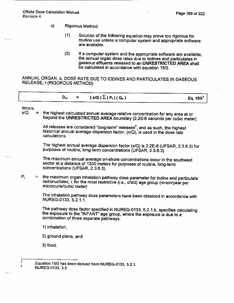
Offsite Dose Calculation Manual Page 169 of 322 Revision 4
c) Rigorous Method
(1) Solution of the following equation may prove too rigorous for routine use unless a computer system and appropriate software are available.
(2) If a computer system and the appropriate software are available, the annual organ dose rates due to iodines and particulates in gaseous effluents released to an UNRESTRICTED AREA shall be calculated in accordance with equation 15G.
ANNUAL ORGAN, o, DOSE RATE DUE TO IODINES AND PARTICULATES IN GASEOUS RELEASE, r (RIGOROUS METHOD)
Dor -- (xQ ) 00(p)(Qr) Eq. 15G'
Where, x/Q = the highest calculated annual average relative concentration for any area at or
beyond the UNRESTRICTED AREA boundary (2.2E-6 seconds per cubic meter)
All releases are considered "long-term" releases 2, and as such, the highest historical annual average dispersion factor, (x/Q), is used in the dose rate calculations.
The highest annual average dispersion factor (x/Q) is 2.2E-6 (UFSAR, 2.3.6.3) for purposes of routine, long-term concentrations (UFSAR, 2.3.6.3).
The maximum annual average on-shore concentrations occur in the southeast sector at a distance of 1300 meters for purposes of routine, long-term concentrations (UFSAR, 2.3.6.3).
Pi = the maximum organ inhalation pathway dose parameter for iodine and particulate radionuclides, i, for the most restrictive (i.e., child) age group (mrem/year per microcurie/cubic meter)
The inhalation pathway dose parameters have been obtained in accordance with NUREG-0133, 5.2.1.1.
The pathway dose factor specified in NUREG-0133, 5.2.1.b, specifies calculating the exposure to the "INFANT" age group, where the exposure is due to a combination of three separate pathways.
1) inhalation,
2) ground plane, and
3) food.
Equation 15G has been derived from NUREG-0133, 5.2.1. 2 NUREG-0133, 3.3

Offsite Dose Calculation Manual Revision 4
Page 170 of 322
The latest NRC guidance has deleted the requirement to include the ground plane and food dose contributions when calculating maximum organ doses, therefore no pathway dose factors are calculated for the ground plane or food pathways.
The latest NRC guidance has changed the critical receptor age group from "infant" to "child."
The child, inhalation pathway dose parameters for various radionuclides, sorted by critical organ, are tabulated in Attachment 12.
It should be noted that the dose parameters, Pi, (listed in Attachment 12) calculated in accordance with NUREG-0133, section 5.2.1.1 and the latest NRC guidance are numerically equal to the "Inhalation Pathway Factors," K1, calculated in accordance with NUREG-0133, section 5.3.1.1. As a result the ODCM does not contain two separate tables for values of Pi and KI.
Qir = the release rate of iodine or particulate radionuclide, i, in (simultaneous) gaseous release, r (microcuries/second).
Calculate the values of Qir for each SIMULTANEOUS RELEASE in accordance with equation 9G.
INSTANTANEOUS RELEASE RATE OF IODINE OR PARTICULATE NUCLIDE i IN GASEOUS RELEASE r
Qir = (Air)w(Fr) (c') Eq. 9G Air = the specific activity of iodine or particulate radionuclide, i, in (simultaneous) release,
r (microcuries/cubic centimeter)
Fr = the discharge flow rate for (simultaneous) release, r (cubic meters per second)
If the discharge flow rate is unknown (e.g., the release has not been conducted), the "Maximum Discharge Flow Rate" listed on Attachments 7 or 8 may be used to calculate the annual organ dose rate.
Additional guidance for calculating discharge flow rates may be contained in approved CHEMISTRY SECTION procedures (e.g., CP-601 and CP-604).
c' = a conversion constant (1 E6 cubic centimeters per cubic meter)
d) simplified method
(1) If a computer system and the appropriate software are NOT available, the annual organ dose rate due to iodines and particulates in gaseous effluents discharged from the site to UNRESTRICTED AREAS may be calculated in accordance with equation 16G.

Offsite Dose Calculation Manual Page 171 of 322 Revision 4
ANNUAL ORGAN, o, DOSE RATE DUE TO IODINES AND PARTICULATES IN GASEOUS RELEASE, r (SIMPLIFIED METHOD)
SDor = (1/Kvt) (x/Q) (Pmax) Y QIr Eq. 16G'
Where, KSf = a constant, actually a safety factor, which is the ratio of the CCNPP organ dose rate
limit to the organ dose rate limit of Control 3.11.2.1, (unitless)
The safety factor chosen shall be less than or equal to 1.00. This ensures the organ dose rate is always less than or equal to the organ dose rate limit of Control 3.11.2.1.
A safety factor of 1.00 will yield an organ dose rate which corresponds to the organ dose rate limit of Control 3.11.2.1.
A safety factor of 0.500 will yield an organ dose which corresponds to one-half the organ dose rate limit of Control 3.11.2.1.
It is recommended that a safety factor of 1.0 be used for calculating the organ dose rate, however, other values-not to exceed 1.00-may be used as directed by the General Supervisor Chemistry.
The particular value selected for the safety factor is somewhat arbitrary, however a safety factor does provide plant personnel with a degree of administrative control over the use of simplified equations for generating radioactive gaseous release permits. This administrative control is designed to minimize the possibility of violating Control 3.11.2.1 when simplifying assumptions are used.
The use of a safety factor is consistent with the ALARA philosophy that licensees should make every reasonable effort to maintain radiation exposures, and releases of radioactive materials in effluents to UNRESTRICTED AREAS, as low as is reasonably achievable.
This safety factor has been included in equation 16G to account for any potential nonconservatism associated with applying the dose parameter, Pmax, to all radionuclides identified in the gaseous release. Such nonconservatism could conceivable be present whenever radionuclides having a dose parameter greater than Pmax are present in a gaseous release.
x/Q = the highest calculated annual average relative concentration for any area at or beyond the UNRESTRICTED AREA boundary (2.2E-6 seconds per cubic meter)
All releases are considered "long-term" releases 2, and as such, the highest historical annual average dispersion factor, (x/Q), is used in the dose rate calculations.
Equation 16G has been derived from NUREG-0133, 5.2.1. 2 NUREG-0133, 3.3

Offsite Dose Calculation Manual Page 172 of 322 Revision 4
The highest annual average dispersion factor (x/Q) is 2.2E-6 (UFSAR, 2.3.6.3) for purposes of routine, long-term concentrations (e.g., routine noble gas releases) (UFSAR, 2.3.6.3).
The maximum annual average on-shore concentrations occur in the southeast sector at a distance of 1300 meters for purposes of routine, long-term concentrations (e.g., routine noble gas releases) (UFSAR, 2.3.6.3).
Pmax = the most restrictive dose parameter which would be reasonably anticipated for the inhalation pathway, child age group, thyroid organ, and 1-131 radionuclide (mrem/year per microcurie/cubic meter)
The inhalation pathway dose parameters have been obtained in accordance with NUREG-0133, 5.2.1.1.
The pathway dose factor specified in NUREG-0133, 5.2.1.b, specifies calculating the exposure to the "INFANT" age group, where the exposure is due to a combination of three separate pathways.
1) inhalation,
2) ground plane, and
3) food.
The latest NRC guidance has deleted the requirement to include the ground plane and food dose contributions when calculating maximum organ doses, therefore no pathway dose factors are calculated for the ground plane or food pathways.
The latest NRC guidance has changed the critical receptor age group from "infant" to "child."
The child, inhalation pathway dose parameters for various radionuclides, sorted by critical organ, are tabulated in Attachment 12.
It should be noted that the dose parameters, Pi, (listed in Attachment 12) calculated in accordance with NUREG-0133, section 5.2.1.1 and the latest NRC guidance are numerically equal to the "Inhalation Pathway Factors," K*, calculated in accordance with NUREG-0133, section 5.3.1.1. As a result the ODCM does not contain two separate tables for values of Pi and K,.
Qir = the release rate of iodine or particulate radionuclide, i, in (simultaneous) gaseous release, r (microcuries/second).
Calculate the values of Qir for each SIMULTANEOUS RELEASE in accordance with equation 9G.

Offsite Dose Calculation Manual Revision 4
Page 173 of 322
INSTANTANEOUS RELEASE RATE OF IODINE OR PARTICULATE NUCLIDE i IN GASEOUS RELEASE r
Qirr = (Air) (Fr) (C') Eq. 9G
Air = the specific activity of iodine or particulate radionuclide, i, in (simultaneous) release,
r (microcuries/cubic centimeter)
Fr = the discharge flow rate for (simultaneous) release, r (cubic meters per second)
If the discharge flow rate is unknown (e.g., the release has not been conducted), the "Maximum Discharge Flow Rate" listed on Attachments 7 or 8 may be used to calculate the annual organ dose rate.
Additional guidance for calculating discharge flow rates may be contained in approved CHEMISTRY SECTION procedures (e.g., CP-601 and CP-604).
c = a conversion constant (1 E6 cubic centimeters per cubic meter)
e) Once the calculations above have been completed, the calculation results are compared to the applicable limits and corrective actions are initiated as described below.
7. Corrective actions
a) CHEMISTRY SECTION surveillance procedures (e.g., CP-213) shall contain/and/or reference administrative and/or Control limits for annual organ dose rates for gaseous effluents and shall specify corrective actions to be initiated when these limits are exceeded.
b) Refer to Control 3.11.2.1 for actions to be taken in the event the calculated annual organ dose rate to any organ exceeds 1500 mr/yr.
CUMULATIVE GAMMA AIR DOSES DUE TO NOBLE GASES IN GASEOUS EFFLUENTS
1. Introduction
a) Appendix I to 10 CFR 50 specifies cumulative gamma air dose limits associated with the release of radioactive materials to UNRESTRICTED AREAS.
b) Radiological effluent controls have been established to implement the requirements of 10 CFR 50, Appendix I.
c) These radiological effluent controls are described below.

Revision 4 -.. . .
2. Radiological Effluent Controls
a) The cumulative gamma air dose, due to noble gases in gaseous effluents released to UNRESTRICTED AREAS, shall be less than 10 mrads in any calendar quarter, and shall be less than 20 mrads in any calendar year (per Control 3.11.2.2)
b) The routine surveillances which are performed to verify compliance with these radiological effluent controls are described below.
3. Surveillance Requirement(s)
a) The cumulative gamma air doses, for the current calendar month, the calendar quarter, and the current calendar year, due to noble gases in gaseous effluents, shall be determined at least once every 60 days (Control 4.11.2.2).
b) The plant group(s) responsible for performing the required surveillance(s) are identified below.
4. Responsible Plant Organizations
a) The CHEMISTRY SECTION is responsible for calculating the cumulative gamma air doses for the current calendar quarter and the current calendar year.
b) The CHEMISTRY SECTION calculates the cumulative gamma air doses whenever the appropriate initiating conditions are present
c) These initiating conditions are contained in the following section.
5. Initiating Conditions
a) The cumulative gamma air doses due to noble gases in gaseous effluents shall be determined at least once per 60 days (Control 4.11.2.2).
b) The cumulative gamma air doses due to noble gases in gaseous effluents shall be calculated for each release of a WGDT (CP-604).
c) The cumulative gamma air doses due to noble gases in gaseous effluents shall be calculated for each vent of a containment building (CP604).
d) The cumulative gamma air doses due to noble gases in gaseous effluents shall be calculated for each PURGE of a containment building (CP-604).
Offsite Dose Calculation Manual Pane_ 17A. nf q1-1

Offsite Dose Calculation Manual Revision 4
Page 175 of 322
e) The cumulative gamma air doses due to noble gases in gaseous effluents shall be calculated at least weekly' for CONTINUOUS discharges from plant vent stacks (CP-612).
f) The cumulative gamma air doses due to noble gases in gaseous effluents shall be calculated for each discharge of combustion products resulting from the burning of contaminated oil.
g) The cumulative gamma air doses due to noble gases in gaseous effluents shall be calculated for each ABNORMAL ANDIOR UNANTICIPATED RADIOACTIVE GAS RELEASE 2 (CP-612).
h) Whenever the correct initiating conditions are present, the cumulative gamma air doses shall be calculated as described below.
6. Calculation Methodology
a) The cumulative gamma air dose at the SITE BOUNDARY (e.g., for the current calendar month, current calendar quarter, current calendar year, or previous 92 days) due to noble gases in gaseous effluents shall be calculated using the following equation3:
The frequency is controlled by the implementing procedure, CP-612, and is based on plant conditions. Under no conditions shall the frequency be less than once per month (Control 4.11.2.1.1 or 4.11.2.1.2, Table 4.11-2). The criteria used to define ABNORMAL AND UNANTICIPATED GAS RELEASES may be found in CP-612 or CP-604. The alarm and trip setpoints ... shall be determined and adjusted in accordance with the methodology and parameters of the ODCM. (Control 3.3.3.9).

Revision 4
CUMULATIVE GAMMA, g, AIR DOSE FOR ALL GASEOUS RELEASES, r, DISCHARGED DURING TIME INTERVAL, t
Dgt = Dgr Eq. 17G
Where, Dgt = the cumulative gamma air dose (mrad) at the SITE BOUNDARY due to noble gas
radionuclides contained in all gaseous radwaste discharged from the site during the time interval, t
Dgr = the cumulative gamma air dose (mrad) at the SITE BOUNDARY due to noble gas radionuclides contained in gaseous radwaste release, r, discharged from the site during the time interval of interest
Calculate the values of Dgr for each gaseous release as described below.
b) At CCNPP, two methods exist for calculating Dgr (i.e., the gamma air dose at the SITE BOUNDARY due to noble gas radionuclides contained in a gaseous radwaste release, r, discharged from the site during a specified time interval).
(1) The rigorous method shall be used IF a computer system and the appropriate software are available.
(2) The simplified method may be used IF a computer system and the appropriate software are NOT available.
(3) These methods, as well as additional supporting information, are
presented in the following sections.
c) rigorous method
(1) Solution of the following equation may prove too rigorous for routine use unless a computer system and appropriate software are available.
(2) If a computer system and the appropriate software are available, the gamma air dose due to noble gases in gaseous effluents released to UNRESTRICTED AREAS shall be calculated in accordance with equation 18G.
Offsite Dose Calculation Manual Page 176 of 322

Offsite Dose Calculation Manual Page 177 of 322 Revision 4
GAMMA AIR DOSE DUE TO NOBLE GASES IN GAS RELEASE, r (RIGOROUS EQUATION)
Dgr = (3.17E-8 )(x/Q )[(Mi) ( Q'ir) Eq. 18G'
Where, 3.17E-8 = The conversion constant, 3.17E-8, represents the inverse of the number of
seconds in a year.
x/Q = the highest calculated annual average relative concentration for any area at or beyond the UNRESTRICTED AREA boundary (2.2E-6 seconds per cubic meter)
All releases are considered "long-term" releases2 , and as such, the highest historical annual average dispersion factor, (xIQ), is used in the dose calculations.
The highest annual average dispersion factor (x/Q) is 2.2E-6 (UFSAR, 2.3.6.3) for purposes of routine, long-term concentrations (e.g., routine noble gas releases) (UFSAR, 2.3.6.3).
The maximum annual average on-shore concentrations occur in the southeast sector at a distance of 1300 meters for purposes of routine, long-term concentrations (e.g., routine noble gas releases) (UFSAR, 2.3.6.3).
Mi = the air dose factor due to gamma emissions for each identified noble gas radionuclide, i (mrad/yr per microcurie/cubic meter)
The gamma air dose factors have been obtained from Regulatory Guide 1.109, Appendix B, Table B-I.
The gamma air dose factors for various noble gas radionuclides are tabulated in Attachment 10.
Q'ir = the total (time averaged) activity of noble gas radionuclide, i, in gaseous release, r
(microcuries).
At CCNPP, all releases are considered long term releases.
Calculate the values of Qir for each release in accordance with equation 19G.
Equation 18G has been derived from NUREG-0133, 5.3.1.. 2 NUREG-01 33, 3.3

Offsite Dose Calculation Manual Revision 4
Page 178 of 322
TOTAL (TIME AVERAGED) ACTIVITY OF NOBLE GAS NUCLIDE i IN GASEOUS RELEASE r
Q'ir = (A )ir) (Fr) (tr) (c') Eq. 19G
Air = the specific activity of noble gas radionuclide, i, in release, r, discharged during the time interval of interest (microcuries/cubic centimeter)
Fr = the discharge flow rate for release, r, discharged during the time interval of interest (cubic meters per second)
If the discharge flow rate is unknown (e.g., the gaseous radwaste has not been released), the "Maximum Discharge Flow Rate" listed on Attachments 7 or 8 may be used to calculate the average activity for nuclide i.
Whenever possible, the actual discharge flow rate determined from actual release conditions (e.g., initial pressure, volume, and temperature of a WGDT along with final pressure and temperature) shall be used in equation 19G.
Additional guidance for calculating discharge flow rates may be contained in approved CHEMISTRY SECTION procedures (e.g., CP-601 and CP-604).
tir = the duration of the gaseous radwaste release (seconds)
c = a conversion constant, 1 E6 cubic centimeters per cubic meter, which represents the number of cubic centimeters per cubic meter.
(3) In the event a computer system is unavailable, a simplified equation may be used to calculate the gamma air dose due to noble gases in gaseous effluents released to UNRESTRICTED AREAS.
(4) The simplified method is presented below.
d) simplified method
(1) If a computer system and appropriate software are NOT available to perform the rigorous gamma air dose calculation described in the previous section, the gamma air dose, due to noble gas radionuclides, in any single release of waste gases discharged to UNRESTRICTED AREAS may be calculated in accordance with equation 20G.

Offsite Dose Calculation Manual Page 179 of 322 Revision 4
GAMMA AIR DOSE DUE TO NOBLE GASES IN GAS RELEASE, r (SIMPLIFIED EQUATION)
Dgr = [ ( 3.17E8 )( x/Q ) ( Mvg ) / Kf ] I Q'ir Eq. 20G'
3.17E-8 = The conversion constant, 3.17E-8, represents the inverse of the number of seconds in a year.
x/Q = the highest calculated annual average relative concentration for any area at or beyond the UNRESTRICTED AREA boundary (2.2E-6 seconds per cubic meter)
All releases are considered "long-term" releases2 , and as such, the highest historical annual average dispersion factor, (x/Q), is used in the dose calculations.
The highest annual average dispersion factor (x/Q) is 2.2E-6 (UFSAR, 2.3.6.3) for purposes of routine, long-term concentrations (e.g., routine noble gas releases) (UFSAR, 2.3.6.3).
The maximum annual average on-shore concentrations occur in the southeast sector at a distance of 1300 meters for purposes of routine, long-term concentrations (e.g., routine noble gas releases) (UFSAR, 2.3.6.3).
Mav = the empirically derived, site specific, average gamma air dose factor for each identified noble gas radionuclide, i (mrad/yr per microcurie/cubic meter)
A site-specific, average, gamma air dose factor has been calculated from historical data.
The calculation of this site-specific, average, gamma air dose factor is presented on Attachment 11 (use section 3.4.5 of the old ODCM.)
K = a constant, actually a safety factor, which is the ratio of the CCNPP gamma air dose limit to the gamma air dose limit of Control 3.11.2.2, (unitless)
The safety factor chosen shall be less than or equal to 1.00. This ensures the gamma air dose is always less than or equal to the gamma air dose limit of Control 3.11.2.2.
A safety factor of 1.00 will yield an gamma air dose which corresponds to the gamma air dose limit of Control 3.11.2.2.
A safety factor of 0.500 will yield an gamma air dose which corresponds to one-half the gamma air dose limit of Control 3.11.2.2.
It is recommended that a safety factor of 1.0 be used for calculating the gamma air dose, however, other values-not to exceed 1.00--may be used as directed by the General Supervisor Chemistry.
Equation 20G has been derived from NUREG-0133, 5.3.1. 2 NUREG-0133, 3.3

Offsite Dose Calculation Manual Page 180 of 322 Revision 4
The particular value selected for the safety factor is somewhat arbitrary, however a safety factor does provide plant personnel with a degree of administrative control over the use of simplified equations for generating radioactive gaseous release permits. This administrative control is designed to minimize the possibility of violating Control 3.11.2.2 when simplifying assumptions are used.
The use of a safety factor is consistent with the ALARA philosophy that licensees should make every reasonable effort to maintain radiation exposures- and releases of radioactive materials in effluents to UNRESTRICTED AREAS, as low as is reasonably achievable.
This safety factor has been included in equation 20G to account for any potential nonconservatism associated with applying the empirically derived gamma air dose factor, Mavg, to all radionuclides identified in the gaseous release. Such nonconservatism could conceivable be present whenever radionuclides having a gamma air dose factor greater than Mavg are present in a gaseous release.
Q'ir = the total (time averaged) activity of noble gas radionuclide, i, in gaseous release, r (microcuries)
At CCNPP, all releases are considered long term releases.
Calculate the values of Qir for each release in accordance with equation 19G.
TOTAL (TIME AVERAGED) ACTIVITY OF NOBLE GAS NUCLIDE i IN GASEOUS RELEASE r
Q1t, = (Air) (Fr) (tr) (C') Eq. 19G
Air = the specific activity of noble gas radionuclide, i, in release, r, discharged during the time interval of interest (microcuries/cubic centimeter).
Fr = the discharge flow rate for release, r, discharged during the time interval of interest (cubic meters per second).
If the discharge flow rate is unknown (e.g., the gaseous radwaste has not been released), the "Maximum Discharge Flow Rate" listed on Attachments 7 or 8 may be used to calculate the average activity for nuclide i.
Additional guidance for calculating discharge flow rates may be contained in approved CHEMISTRY SECTION procedures (e.g., CP-601 and CP-604).
tir = the duration of the gaseous radwaste release (seconds).
c' = a conversion constant, 1 E6 cubic centimeters per cubic meter, which represents the number of cubic centimeters per cubic meter.

Offsite Dose Calculation Manual Page 181 of 322 Revision 4
e) Once the calculations above have been completed, the calculation results are compared to the applicable limits and corrective actions are initiated as described below.
7. Corrective actions
a) CHEMISTRY SECTION surveillance procedures (e.g., CP-213) shall contain/and or reference administrative and/or Control limits for quarterly and yearly gamma air doses for gaseous effluents and shall specify corrective actions to be initiated when these limits are exceeded.
b) Refer to Control 3.11.2.2 for actions to be taken in the event the calculated cumulative gamma air doses exceed 10 mrads per calendar quarter or 20 mrads per calendar year.
CUMULATIVE BETA AIR DOSES DUE TO NOBLE GASES IN GASEOUS EFFLUENTS
1 . Introduction
a) Appendix I to 10 CFR 50 specifies cumulative beta air dose limits associated with the release of radioactive materials to UNRESTRICTED AREAS.
b) Radiological effluent controls have been established to implement the requirements of 10 CFR 50, Appendix I.
c) These radiological effluent controls are described below.
2. Radiological Effluent Controls
a) The cumulative beta air dose, due to noble gases in gaseous effluents released to UNRESTRICTED AREAS, shall be less than 20 mrads in any calendar quarter, and shall be less than 40 mrads in any calendar year (per Control 3.11.2.2)
b) The routine surveillances which are performed to verify compliance with these radiological effluent controls are described below.
3. Surveillance Requirement(s)
a) The cumulative beta air doses, for the current calendar quarter and the current calendar year, due to noble gases in gaseous effluents, shall be determined at least once every 60 days (Control 4.11.2.2).
b) The plant group(s) responsible for performing the required surveillance(s) are identified below.
4. Responsible Plant Organizations
a) The CHEMISTRY SECTION is responsible for calculating the cumulative beta air doses for the current calendar quarter and the current calendar year.

Offsite Dose Calculation Manual Page 182 of 322 Revision 4
b) The CHEMISTRY SECTION calculates the cumulative beta air doses whenever the appropriate initiating conditions are present
c) These initiating conditions are contained in the following section.
5. Initiating Conditions
a) The cumulative beta air doses due to noble gases in gaseous effluents shall be determined at least once per 60 days (Control 4.11.2.2).
b) The cumulative beta air doses due to noble gases in gaseous effluents are calculated for each release of a WGDT (CP-604).
c) The cumulative beta air doses due to noble gases in gaseous effluents are calculated for each vent of a containment building (CP-604).
d) The cumulative beta air doses due to noble gases in gaseous effluents are calculated for each PURGE of a containment building (CP-604).
e) The cumulative beta air doses due to noble gases in gaseous effluents are calculated at least weekly1 for CONTINUOUS discharges from plant vent stacks (CP-612).
f) The cumulative beta air doses due to noble gases in gaseous effluents are calculated for each discharge of combustion products resulting from the burning of contaminated oil.
g) The cumulative beta air doses due to noble gases in gaseous effluents are calculated for each ABNORMAL ANDIOR UNANTICIPATED RADIOACTIVE GAS RELEASE2 (CP-612).
h) Whenever the correct initiating conditions are present, the cumulative
beta air doses shall be calculated as described below.
6. Calculation Methodology
a) The cumulative beta air doses (e.g., for the current calendar month, current calendar quarter, current calendar year, or previous 92 days) due to noble gases in gaseous effluents shall be calculated in accordance with equation 21G.
The frequency is controlled by the implementing procedure, CP-612, and is based on plant conditions. Under no conditions shall the frequency be less than once per month (Controls 4.11.2.1.1 or 4.11.2.1.2, Table 4.11-2). The criteria used to define ABNORMAL AND UNANTICIPATED GAS RELEASES may be found in CP-612 or CP-604.

Offsite Dose Calculation Manual Revision 4
Page 183 of 322
CUMULATIVE BETA AIR DOSE FOR ALL GASEOUS RELEASES, r, DISCHARGED DURING TIME INTERVAL, t
D = Dir Eq. 21G1
Where, Dat = the cumulative beta air dose (mrad) at the SITE BOUNDARY due to noble gas
radionuclides contained in all gaseous radwaste discharged from the site during the time interval, t
Dar = the beta air dose (mrad) due to noble gas radionuclides contained in gaseous radwaste release, r, discharged from the site during the time interval of interest
Calculate the values of Dar for each gaseous release as described below.
b) At CCNPP, two methods exist for calculating Dar (the beta air dose at the SITE BOUNDARY due to noble gas radionuclides contained in a gaseous radwaste release, r, discharged from the site).
(1) The rigorous method shall be used IF a computer system and the appropriate software are available.
(2) The simplified method may be used IF a computer system and the appropriate software are NOT available.
(3) These methods, as well as additional supporting information, are presented in the following sections.
c) Rigorous method
(1) Solution of the following equation may prove too rigorous for routine use unless a computer system and appropriate software are available.
(2) If a computer system and the appropriate software are available, the cumulative beta air dose due to noble gases in gaseous effluents released to UNRESTRICTED AREAS shall be calculated in accordance with equation 22G.

Offsite Dose Calculation Manual Page 184 of 322 Revision 4
BETA AIR DOSE DUE TO NOBLE GASES IN GAS RELEASE, r (RIGOROUS EQUATION)
D(3.17E-)(xIQ) I [(NI)(0,,)] Eq. 22GI
Where, Dar = the beta air dose due to noble gas radionuclides contained in gaseous radwaste
release, r, discharged from the site during the time interval of interest
3.17E-8 = The conversion constant, 3.17E-8, represents the inverse of the number of seconds in a year.
x/Q = the highest calculated annual average relative concentration for any area at or beyond the UNRESTRICTED AREA boundary (2.2E-6 seconds per cubic meter)
All releases are considered "long-term" releases2 , and as such, the highest historical annual average dispersion factor, (x/Q), is used in the dose calculations.
The highest annual average dispersion factor (x/Q) is 2.2E-6 (UFSAR, 2.3.6.3) for purposes of routine, long-term concentrations (e.g., routine noble gas releases) (UFSAR, 2.3.6.3).
The maximum annual average on-shore concentrations occur in the southeast sector at a distance of 1300 meters for purposes of routine, long-term concentrations (e.g., routine noble gas releases) (UFSAR, 2.3.6.3).
Ni = the air dose factor due to beta emissions for each identified noble gas radionuclide, i (mrad/yr per microcurie/cubic meter)
The beta air dose factors have been obtained from Regulatory Guide 1.109, Appendix B, Table B-1.
The beta air dose factors for various noble gas radionuclides are tabulated in Attachment 10 (Attachment I of old ODCM).
Q'ir = the total (time averaged) activity of noble gas radionuclide, i, in gaseous release, r (microcuries).
At CCNPP, all releases are considered long term releases.
Calculate the values of Qir for each release in accordance with equation 19G.
1 Equation 22G has been derived from NUREG-0133, 5.3.1. 2 NUREG-01 33, 3.3

Offsite Dose Calculation Manual Revision 4
Page 185 of 322
TOTAL (TIME AVERAGED) ACTIVITY OF NOBLE GAS NUCLIDE i IN GASEOUS RELEASE r
Qir = (A4r) (F,) (tlr) (c') Eq. 19G
Air = the specific activity of noble gas radionuclide, i, in release, r, discharged during the time interval of interest (microcuries/cubic centimeter).
Fr = the discharge flow rate for release, r, discharged during the time interval of interest (cubic meters per second).
If the discharge flow rate is unknown (e.g., the gaseous radwaste has not been released), the "Maximum Discharge Flow Rate" listed on Attachments 7 or 8 may be used to calculate the average activity for nuclide i.
Additional guidance for calculating discharge flow rates may be contained in approved CHEMISTRY SECTION procedures (e.g., CP-601 and CP-604).
tlr = the duration of the gaseous radwaste release (seconds).
cl = a conversion constant, 1 E6 cubic centimeters per cubic meter.
(3) In the event a computer system is unavailable, a simplified equation may be used to calculate the gamma air dose due to noble gases in gaseous effluents released to UNRESTRICTED AREAS
(4) The simplified method is presented below.
d) Simplified method
(1) If a computer system and the appropriate software are NOT available to perform the rigorous beta air dose calculation described in the previous section, the beta air dose resulting from a single release of waste gases discharged to UNRESTRICTED AREAS may be calculated in accordance with equation 23G.

Offsite Dose Calculation Manual Page 186 of 322 Revision 4
BETA AIR DOSE DUE TO NOBLE GASES IN GAS RELEASE, r (SIMPLIFIED EQUATION)
Dar = [(3.17E-8)(XIQ)(Navg)/Kf] "1'ir Eq. 23G'
3.17E-8 = The conversion constant, 3.17E-8, represents the inverse of the number of seconds in a year.
x/Q = the highest calculated annual average relative concentration for any area at or beyond the UNRESTRICTED AREA boundary (2.2E-6 seconds per cubic meter)
All releases are considered "long-term" releases2 , and as such, the highest historical annual average dispersion factor, (x/Q), is used in the dose calculations.
The highest annual average dispersion factor (x/Q) is 2.2E-6 (UFSAR, 2.3.6.3) for purposes of routine, long-term concentrations (e.g., routine noble gas releases) (UFSAR, 2.3.6.3).
The maximum annual average on-shore concentrations occur in the southeast sector at a distance of 1300 meters for purposes of routine, long-term concentrations (e.g., routine noble gas releases) (UFSAR, 2.3.6.3).
Navg = the empirically derived, site specific, average beta air dose factor for each identified noble gas radionuclide, i (mrad/yr per microcurie/cubic meter)
A site-specific, average, beta air dose factor has been calculated from historical data.
The calculation of this site-specific, average, beta air dose factor is presented on Attachment 11.
Ksf = a constant, actually a safety factor, which is the ratio of the CCNPP beta air dose limit to the beta air dose limit of Control 3.11.2.2, (unitless)
The safety factor chosen shall be less than or equal to 1.00. This ensures the beta air dose is always less than or equal to the beta air dose limit of Control 3.11.2.2.
A safety factor of 1.00 will yield an organ dose which corresponds to the beta air dose limit of Control 3.11.2.2.
A safety factor of 0.500 will yield an beta air dose which corresponds to one-half the beta air dose limit of Control 3.11.2.2.
It is recommended that a safety factor of 1.0 be used for calculating the beta air dose, however, other values-not to exceed 1.00-may be used as directed by the General Supervisor Chemistry.
I Equation 23G has been derived from NUREG-0133, 5.3.1. 2 NUREG-01 33, 3.3

Offsite Dose Calculation Manual Page 187 of 322 Revision 4
The particular value selected for the safety factor is somewhat arbitrary, however a safety factor does provide plant personnel with a degree of administrative control over the use of simplified equations for generating radioactive gaseous release permits. This administrative control is designed to minimize the possibility of violating Control 3.11.2.2 when simplifying assumptions are used.
The use of a safety factor is consistent with the ALARA philosophy that licensees should make every reasonable effort to maintain radiation exposures,-and releases of radioactive materials in effluents to UNRESTRICTED AREAS, as low as is reasonably achievable.
This safety factor has been included in equation 23G to account for any potential nonconservatism associated with applying the empirically derived beta air dose factor, Navg, to all radionuclides identified in the gaseous release. Such nonconservatism could conceivable be present whenever radionuclides having a beta air dose factor greater than Navg are present in a gaseous release.
Q'ir = the total (time averaged) activity of noble gas radionuclide, i, in gaseous release, r (microcuries)
At CCNPP, all releases are considered long term releases.
Calculate the values of Qir for each release in accordance with equation 19G.
TOTAL (TIME AVERAGED) ACTIVITY OF NOBLE GAS NUCLIDE i IN GASEOUS RELEASE r
Qir -- (Air) (Fr)(tir) ( c') Eq. 19G
Air = the specific activity of noble gas radionuclide, i, in release, r, discharged during the time interval of interest (microcuries/cubic centimeter)
Fr = the discharge flow rate for release, r, discharged during the time interval of interest (cubic meters per second)
If the discharge flow rate is unknown (e.g., the gaseous radwaste has not been released), the "Maximum Discharge Flow Rate" listed on Attachments 7 or 8 may be used to calculate the average activity for nuclide i.
Additional guidance for calculating discharge flow rates may be contained in approved CHEMISTRY SECTION procedures (e.g., CP-601 and CP-604).
tlr = the duration of the gaseous radwaste release (seconds).
c' = a conversion constant, 1 E6 cubic centimeters per cubic meter.
e) Once the calculations above have been completed, the calculation results are compared to the applicable limits and corrective actions are initiated as described below.

Offsite Dose Calculation Manual Page 188 of 322 Revision 4
7. Corrective actions
a) CHEMISTRY SECTION surveillance procedures (e.g., CP-213) shall contain/and or reference administrative and/or Control limits for quarterly and yearly beta air doses for gaseous effluents and shall specify corrective actions to be initiated when these limits are exceeded.
b) Refer to Control 3.11.2.2 for actions to be taken in the event the calculated cumulative beta air doses exceed 20 mrads per calendar quarter or 40 mrads per calendar year.
CUMULATIVE ORGAN DOSES DUE TO IODINES AND PARTICULATES IN GASEOUS EFFLUENTS
1. Introduction
a) Appendix I to 10 CFR 50 specifies cumulative organ dose limits associated with the release of radioactive materials to UNRESTRICTED AREAS.
b) Radiological effluent controls have been established to implement the requirements of 10 CFR 50, Appendix I.
c) These radiological effluent controls are described below.
2. Radiological Effluent Controls
a) The cumulative organ dose due to iodines and particulates in gaseous effluents released to UNRESTRICTED AREAS shall be less than 15 mrems per calendar quarter, and shall be less than 30 mrems per calendar year (per Control 3.11.2.3).
b) The cumulative organ dose due to iodines and particulates in gaseous, contaminated oil combustion products released to UNRESTRICTED AREAS shall be less than 0.015 mrems per quarter, and shall be less than 0.030 mrems per year (per Control 3.11.2.3).
c) The routine surveillances which are performed to verify compliance with this radiological effluent controls are described below.
3. Surveillance Requirements
a) The cumulative organ doses (due to iodines and particulates in gaseous waste discharged to UNRESTRICTED AREAS), for the current calendar month, the current calendar quarter, and the current calendar year, shall be determined at least once every 60 days in accordance with the ODCM (per Control 4.11.2.3).
b) The plant group(s) responsible for performing the required surveillances are identified below.

Offsite Dose Calculation Manual Page 189 of 322 Revision 4
4. Responsible Plant Organizations
a) The CHEMISTRY SECTION is responsible for implementing the surveillances required by Control 4.11.2.3.
b) The CCNPP CHEMISTRY SECTION calculates the cumulative organ doses whenever the appropriate initiating conditions are present
c) These initiating conditions are contained in the following section.
5. Initiating Conditions
a) The cumulative organ dose-for each organ-shall be determined at least once per 60 days (Control 4.11.2.2).
b) The cumulative organ dose-for each organ-due to iodines and particulates in gaseous effluents shall be calculated at least weekly1 for CONTINUOUS discharges from plant vent stacks (CP-612).
c) The cumulative organ dose-for each organ-due to iodines and particulates in gaseous effluents shall be calculated for each discharge of combustion products resulting from the burning of contaminated oil.
d) The cumulative organ dose-for each organ-due to iodines and particulates in gaseous effluents shall be calculated for each ABNORMAL ANDIOR UNANTICIPATED RADIOACTIVE GAS RELEASE (CP-612).
e) Whenever the correct initiating conditions are present, the annual cumulative organ doses shall be calculated as described below.
6. Calculation Methodology
a) The cumulative organ doses (for the calendar month, calendar quarter, previous 92 days, and calendar year) due to iodines and particulates in gaseous waste discharged to UNRESTRICTED AREAS shall be calculated in accordance with equation 24G.
The frequency is controlled by the implementing procedure, CP-612, and is based on plant conditions. Under no conditions shall the frequency be less than once per month (Controls 4.11.2.1.1 or 4.11.2.1.2, Table 4.11-2).

Offsite Dose Calculation Manual Revision 4
Page 190 of 322
CUMULATIVE DOSE TO ORGAN, o, FROM ALL GASEOUS RELEASES, r, DISCHARGED DURING TIME INTERVAL, t
Dt = Dor Eq. 24G
Where, Dot = the cumulative dose (mrad) to organ, o, at the SITE BOUNDARY, due to iodine and
particulate radionuclides contained in gaseous waste discharged from the site during the time interval, t
Dor = the dose (mrad) to organ, o, at the SITE BOUNDARY due to iodine and particulate radionuclides in gaseous release, r, discharged from the site during the time interval of interest
Calculate the values of Dor for each gaseous release as described below.
b) At CCNPP, two methods exist for calculating Dor (the organ doses due to iodines and particulates resulting from any single release of radioactive gases to an UNRESTRICTED AREA).
(1) The rigorous method shall be used IF a computer system and the appropriate software are available.
(2) The simplified method may be used IF a computer system and the appropriate software are NOT available.
(3) These methods, as well as additional supporting information, are
presented in the following sections.
c) Rigorous method
(1) Application of the following equation may prove too rigorous for routine use unless a computer system and the appropriate software are available.
(2) If a computer system and the appropriate software are available, the organ doses due to iodines and particulates contained in any single release of radioactive gases to UNRESTRICTED AREAS shall be calculated in accordance with equation 25G.

Offsite Dose Calculation Manual Page 191 of 322 Revision 4
DOSE TO ORGAN, o, DUE TO IODINES AND PARTICULATES IN GAS RELEASE, r (RIGOROUS EQUATION)
Dor - (3.17E-8)( W, )(R a)(Q',,) Eq. 25G'
Where, Dor = the dose (mrem) to organ, o, at the SITE BOUNDARY due to iodine and particulate
radionuclides in gaseous release, r, discharged from the site during the time interval of interest
3.17E-8 = The conversion constant, 3.17E-8, represents the inverse of the number of seconds in a year.
Wv = the dispersion parameter for estimating the dose to an individual at the controlling location for long term releases, and may assume one of two values as described below
W, is x/Q for the inhalation pathway (2.2E-6 sec/cubic meter)
W. is D/Q for the food and ground plane pathways (meters-2)
D/Q = the dispersion parameter at the controlling location for long term releases (meters-2)
The value for D/Q has been determined to be 8.63E-10 M-2.2
The grass-cow-milk pathway is the controlling pathway.3
The controlling sector is the south-southwest sector.
The controlling location is at a distance of 4800 meters.3
Ripao= the dose factor for each identified iodine or particul te radionuclide, i, exposure pathway, p, receptor age group, a, and organ, o (m mrem/year per microcuries/second or mrem/year per microcuries/cubic meter)
dose factors have been derived for the following pathways
1) inhalation - see Attachment 12
2) ground plane - see Attachment 12
3) grass-cow-milk - see Attachment 12
4) grass-cow-meat - see Attachment 12
5) vegetation - see Attachment 12
1 Equation 25G has been derived from NUREG-0133, 5.3.1. 2 See CP-607, Revision 2 section 3.4.3. 3 See the "Land Use Survey", 1990.

Offsite Dose Calculation Manual Page 192 of 322 Revision 4
The inhalation pathway dose factors were obtained using the formula from NUREG0133, 5.3.1.1.
The ground plane dose factors were obtained using the formula from NUREG-0133, 5.3.1.2.
The grass-cow-milk pathway dose factors were obtained using the formula from NUREG-0133, 5.3.1.3.
The grass-cow-meat pathway dose factors were obtained using the formula from NUREG-0133, 5.3.1.4.
The vegetation pathway dose factors were obtained using the formula from NUREG-0133, 5.3.1.5.
Q'ir = the total (time averaged) activity of iodine or particulate radionuclide, i, in gaseous release, r, discharged during the specified time interval (microcuries)
At CCNPP, all releases are considered long term releases.
Calculate the values of Qir for each release in accordance with equation 19G.
TOTAL (TIME AVERAGED) ACTIVITY OF IODINE OR PARTICULATE NUCLIDE i IN GASEOUS RELEASE r
a - ( Air4) ( Fr) ( tir )(C') Eq. 19G
Air = the specific activity of iodine and particulate radionuclide, i, in release, r, discharged during the time interval of interest (microcuries/cubic centimeter)
Fr = the discharge flow rate for release, r, discharged during the time interval of interest (cubic meters per second)
If the discharge flow rate is unknown (e.g., the gaseous radwaste has not been released), the "Maximum Discharge Flow Rate" listed on Attachments 7 or 8 may be used to calculate the average activity for nuclide i.
Additional guidance for calculating discharge flow rates may be contained in approved CHEMISTRY SECTION procedures (e.g., CP-601 and CP-604).
tir = the duration of the gaseous radwaste release (seconds)
c' = a conversion constant, 1 E6 cubic centimeters per cubic meter
(3) In the event a computer system and the appropriate software are unavailable, a simplified equation may be used to calculate the organ doses due to individual gaseous releases.
(4) The simplified method is presented below.

Offsite Dose Calculation Manual Page 193 of 322 Revision 4
d) simplified method
(1) If a computer system and appropriate software are NOT available to perform the rigorous organ dose calculations described in the previous section, the organ doses due to iodines and particulates in a single release of radioactive gases discharged to an UNRESTRICTED AREA may be calculated in accordance with equation 26G.
DOSE TO ORGAN, o, FROM IODINES AND PARTICULATES IN GAS RELEASE, r (SIMPLIFIED EQUATION)
Dmaxor = [(3.17E-8)(W,)(R. 1 31 )/K~ 1]X (Q'ir) Eq.26G1
Dmaxor = the maximum dose to any organ, o, due to iodines and particulates contained in any single release, r, of radioactive gases to an UNRESTRICTED AREA
3.17E-8 = The conversion constant, 3.17E-8, represents the inverse of the number of seconds in a year.
D/Q = the dispersion parameter at the controlling location for long term releases (meters-2)
The value for D/Q has been determined to be 8.63E-10 m-2.2
The grass-cow-milk pathway is the controlling pathway.3
The controlling sector is the south-southwest sector.
The controlling location is at a distance of 4800 meters.3
RI.131 = the infant, thyroid, dose factor for 1-131 via the grass-cow-milk pathway (M2
mrem/year per microcuries/second)
This value is 1.05E12 and it is listed on Attachment 12.
Ksf = a constant, actually a safety factor, which is the ratio of the CCNPP organ dose limit to the organ dose limit of Control 3.11.2.3, (unitless)
The safety factor chosen shall be less than or equal to 1.00. This ensures the organ dose is always less than or equal to the organ dose limit of Control 3.11.2.3.
A safety factor of 1.00 will yield an organ dose which corresponds to the organ dose limit of Control 3.11.2.3.
A safety factor of 0.500 will yield an organ dose which corresponds to one-half the organ dose limit of Control 3.11.2.3.
Equation 26G has been derived from NUREG-0133, 5.3.1. 2 See CP-607, Revision 2 section 3.4.3. 3 See the "Land Use Survey", 1990.

Offsite Dose Calculation Manual Page 194 of 322 Revision 4
It is recommended that a safety factor of 1.0 be used for calculating the organ dose, however, other values-not to exceed 1.00-may be used as directed by the General Supervisor Chemistry.
The particular value selected for the safety factor is somewhat arbitrary, however a safety factor does provide plant personnel with a degree of administrative control over the use of simplified equations for generating radioactive gaseous release permits. This administrative control is designed to minimize the possibility of violating Control 3.11.2.3 when simplifying assumptions are used. The use of a safety factor is consistent with the ALARA philosophy that licensees should make every reasonable effort to maintain radiation exposures, and releases of radioactive materials in effluents to UNRESTRICTED AREAS, as low as is reasonably achievable.
This safety factor has been included in equation 26G to account for any potential nonconservatism associated with applying the infant, thyroid, grass-cow-milk dose factor, R1.131, to all radionuclides identified in the gaseous release. Such nonconservatism could conceivable be present whenever radionuclides having a pathway dose factor greater than R1. 131 are present in a gaseous release.
Q'ir = the total (time averaged) activity of iodine or particulate radionuclide, i, in gaseous release, r (microcuries)
At CCNPP, all releases are considered long term releases.
This value shall be calculated in accordance with equation 19G.
TOTAL (TIME AVERAGED) ACTIVITY OF IODINE OR PARTICULATE NUCLIDE i IN GASEOUS RELEASE r
CiQ'ir = (Air) (Fr) (tir) (C') Eq. 19G
Air = the specific activity of iodine and particulate radionuclide, i, in release, r, discharged during the time interval of interest (microcuries/cubic centimeter)
Fr = the discharge flow rate for release, r, discharged during the time interval of interest (cubic meters per second)
If the discharge flow rate is unknown (e.g., the gaseous radwaste has not been released), the "Maximum Discharge Flow Rate" listed on Attachments 7 or 8 may be used to calculate the average activity for nuclide i. Additional guidance for calculating discharge flow rates may be contained in approved CHEMISTRY SECTION procedures (e.g., CP-601 and CP-604).
tir = the duration of the gaseous radwaste release (seconds)
C! = a conversion constant, 1 E6 cubic centimeters per cubic meter

Offsite Dose Calculation Manual Page 195 of 322 Revision 4
e) Once the calculations above have been completed, the calculation results are compared to the applicable limits and corrective actions are initiated as described below.
7. Corrective actions
a) CHEMISTRY SECTION surveillance procedures (e.g., CP-213) shall contain/and or reference administrative and/or Control limits for cumulative organ dose for gaseous effluents and shall specify corrective actions to be initiated when these limits are exceeded.
b) Refer to Control 3.11.2.3 for actions to be taken in the event the calculated cumulative gamma air doses exceed any of the radiological effluent controls listed above.
LIMITS FOR THE GASEOUS WASTE PROCESSING SYSTEM
1. Introduction
a) 10 CFR 50.36a requires licensees to maintain and use the equipment installed in the gaseous waste processing system for the purpose of controlling effluents to the environment.
b) Radiological effluent controls have been established to implement the requirements of 10 CFR 50.36a.
c) These radiological effluent controls are described below.
2. Radiological effluent controls
a) The GASEOUS RADWASTE TREATMENT SYSTEM and the VENTILATION EXHAUST TREATMENT SYSTEM shall be used to reduce radioactive materials in gaseous waste prior to their discharge when the gaseous effluent air dose, to areas at and beyond the SITE BOUNDARY, exceeds 1.20 mrads gamma radiation in a 92 day period (per Control 3.11.2.4).
b) The GASEOUS RADWASTE TREATMENT SYSTEM and the VENTILATION EXHAUST TREATMENT SYSTEM shall be used to reduce radioactive materials in gaseous waste prior to their discharge when the gaseous effluent air dose, to areas at and beyond the SITE BOUNDARY, exceeds 2.4 mrads beta radiation in a 92 day period (per Control 3.11.2.4).
c) The VENTILATION EXHAUST TREATMENT SYSTEM shall be used to reduce the quantity of radioactive materials in gaseous waste prior to their discharge when the calculated doses due to gaseous effluent releases, to areas at and beyond the SITE BOUNDARY exceeds 1.80 mrem to any organ in a 92 day period (per Control 3.11.2.4).
d) The routine surveillances which are performed to verify compliance with this radiological effluent controls are described below.

Offsite Dose Calculation Manual Page 196 of 322 Revision 4
3. Surveillance Requirement(s)
a) The cumulative gamma air dose, for the previous 92 days, due to noble gases in gaseous effluents, shall be determined at least once every 60 days (Control 4.11.2.2).
b) The plant group(s) responsible for performing the required surveillance(s) are identified below.
4. Responsible Plant Organizations
a) The CHEMISTRY SECTION is responsible for calculating the cumulative gamma air doses for the current calendar month, the previous 92 days, the current calendar quarter, and the current calendar year.
b) The cumulative gamma air dose for the previous 92 days is calculated whenever the appropriate initiating conditions are present
c) These initiating conditions are contained in the following section.
5. Initiating conditions
a) For a listing of initiating conditions associated with calculating gamma air doses, see "Initiating Conditions" in the section of the ODCM titled, "Cumulative Gamma Air Doses Due To Noble Gases In Gaseous Effluents."
b) For a listing of initiating conditions associated with calculating beta air doses, see "Initiating Conditions" in the section of the ODCM titled, "Cumulative Beta Air Doses Due To Noble Gases In Gaseous Effluents."
c) For a listing of initiating conditions associated with calculating cumulative organ doses, see "Initiating Conditions" in the section of the ODCM titled, "Cumulative Organ Doses Due To lodines And Particulates In Gaseous Effluents."
6. Calculation methodology
a) Calculate the previous 92-day cumulative gamma air dose as described in the section "Cumulative Gamma Air Doses Due To Noble Gases In Gaseous Effluents."
b) Calculate the previous 92-day cumulative beta air dose as described in the section "Cumulative Beta Air Doses Due To Noble Gases In Gaseous Effluents."
c) Calculate the previous 92-day cumulative organ dose as described in the section "Cumulative Organ Doses Due To lodines And Particulates In Gaseous Effluents."

Offsite Dose Calculation Manual Page 197 of 322 Revision 4
7. Corrective actions
a) CHEMISTRY SECTION surveillance procedures (e.g., CP-212) shall contain/and or reference administrative and/or Control limits for 92-day cumulative gamma, beta, or organ doses for gaseous effluents and shall specify corrective actions to be initiated when these limits are exceeded.
b) Refer to Control 3.11.2.4 for actions to be taken in the event the calculated 92-day cumulative gamma air, beta air, or organ doses exceed any of the radiological effluent controls listed above.
LIMITS ON TOTAL ANNUAL DOSE - GASES, LIQUIDS, AND URANIUM FUEL CYCLE SOURCES
1 . Introduction
a) 40 CFR 190 specifies annual dose limits for radionuclides released to the environment.
b) Radiological effluent controls have been established to implement the requirements of 40 CFR 190.
c) These radiological effluent controls are described below.
2. Radiological effluent controls
a) The total body dose from exposure to the combination of liquid releases, gas releases, and uranium fuel cycle sources shall be less than 25 mrem for the current calendar year (per Control 3.11.4).
b) The organ dose (for the maximum exposed organ, not including the thyroid) from exposure to the combination of liquid releases, gas releases, and uranium fuel cycle sources shall be less than 25 mrem for the current calendar year (per Control 3.11.4).
c) The thyroid dose from exposure to the combination of liquid releases, gas releases, and uranium fuel cycle sources shall be less than 75 mrem for the current calendar year (per Control 3.11.4).
d) The routine surveillances which are performed to verify compliance with these radiological effluent controls are described below.
3. Surveillance Requirements
a) The cumulative gamma air doses, for current calendar month, the current calendar quarter, and the current calendar year, due to noble gases in gaseous effluents, shall be determined at least once every 60 days (Control 4.11.2.2).
b) The cumulative organ doses (due to iodines and particulates in gaseous waste discharged to UNRESTRICTED AREAS), for the current calendar month, the current calendar quarter, and the current calendar year, shall be determined at least once every 60 days in accordance with the ODCM (per Control 4.11.2.3).

Offsite Dose Calculation Manual Page 198 of 322 Revision 4
C) Cumulative total body dose to MEMBERS OF THE PUBLIC in UNRESTRICTED AREAS-for the current calendar month, the calendar quarter, and the current calendar year-shall be calculated at least once per 60 days (per Control 4.11.1.2).
d) Cumulative organ doses to MEMBERS OF THE PUBLIC in UNRESTRICTED AREAS--for the current calendar month, the current calendar quarter, and the current calendar year-shall be calculated at least once per 60 days (per Control 4.11.1.2).
e) The direct radiation dose to MEMBERS OF THE PUBLIC exposed to uranium fuel cycle sources (i.e., reactor units and outside storage tanks) shall be determined IF THE APPROPRIATE INITIATING CONDITIONS ARE PRESENT.
4. Responsible Plant Organization(s)
a) The CHEMISTRY SECTION is responsible for implementing the effluent surveillances required by Control 4.11.4.1.
b) The CHEMISTRY SECTION is responsible for ensuring implementation of the direct radiation surveillances required by Control 4.11.4.2.
c) IT SHOULD BE NOTED THAT NO SURVEILLANCES NEED BE PERFORMED UNLESS THE APPROPRIATE INITIATING CONDITIONS ARE PRESENT.
d) These initiating conditions are contained in the following section.
5. Initiating conditions
a) The total dose from liquid releases, gas releases, and uranium fuel cycle sources shall be determined whenever the calculated doses from liquid effluents exceed any of the following (per Control 4.11.4.2):
(1) Six (6) mrem per quarter to the total body
(2) Twelve (12) mrem per calendar year to the total body
(3) Twenty (20) mrem per quarter to any organ
(4) Forty (40) mrem per calendar year to any organ
b) The total dose from liquid releases, gas releases, and uranium fuel cycle sources shall be determined whenever the calculated air doses from noble gasses in gaseous effluents exceed any of the following (per Control 4.11.4.2):
(1) Twenty (20) mrad gamma per quarter
(2) Forty (40) mrad gamma per calendar year
(3) Forty (40) mrad beta per quarter

Offsite Dose Calculation Manual Page 199 of 322 Revision 4
(4) Eighty (80) mrad beta per calendar year
C) The total dose from liquid releases, gas releases, and uranium fuel cycle sources shall be determined whenever the calculated organ doses from iodines and particulates in gaseous effluents exceed any of the following (per Control 4.11.4.2):
(1) Thirty (30) mrem per quarter to any organ
(2) Sixty (60) mrem per calendar year to any organ
d) Whenever the correct initiating conditions are present, the total doses from liquid releases, gas releases, and uranium fuel cycle sources (for the calendar year) shall be calculated as shown below.
6. Calculation methodology
a) The total body dose and the organ doses from liquid releases, gas releases, and uranium fuel cycle sources (for the calendar year) shall be calculated in accordance with equation 1T and 2T respectively.
TOTAL, TOTAL BODY DOSE FROM LIQUID RELEASES, GAS RELEASES, AND URANIUM FUEL CYCLE SOURCES
Dtbali = DToL + Dgt + Dtank Eq. 1T
TOTAL ORGAN DOSES FROM LIQUID RELEASES, GAS RELEASES, AND URANIUM FUEL CYCLE SOURCES
Doall = DToL + Dot + Drank Eq. 2T
Dtba, = the dose (mrem) to total body resulting from the combination of all gas releases, all liquid releases, and all uranium fuel cycle sources.
Doall = the dose (mrem) to organ, o, resulting from the combination of all gas releases, all liquid releases, and all uranium fuel cycle sources.
Separate values shall be calculated for each of the organs listed below:
1. bone
2. liver
3. thyroid
4. kidney
5. lung
6. GI tract
Offsite Dose Calculation Manual Page 200 of 322 Revision 4 DToL = the cumulative dose (mrem) to organ, 0, for all liquid releases discharged in a given
time interval
Calculate this value as specified by equation 8L.
Dgt = the site-boundary cumulative gamma air dose (mrad) due to noble gas radionuclides contained in all gaseous radwaste discharged from the site during the time interval, t
Calculate this value as specified by equation 17G, except substitute I• for Mi (see Attachment 10).
Dot = the site-boundary cumulative organ dose (mrem) resulting from the release of iodine and particulate radionuclides in gaseous releases from the site
Calculate this value as specified by equation 24G.
Drank = the calendar-year cumulative dose (mrem) to the maximum exposed MEMBER OF THE PUBLIC due to direct radiation from the reactor units and outside storage tanks
This value shall be based on the results of direct radiation measurements from TLDs or continuous dose rate instruments placed near the SITE BOUNDARY (e.g., from radiological environmental monitoring sites DR1-DR9 described on Attachment 13 and shown on Attachment 18).
The CHEMISTRY SECTION, and the Radiation Safety Section are responsible for determining this value.
b) Compare the calculated values to the radiological effluent controls (listed in this section), and if any of the radiological effluent controls have been exceeded, perform the appropriate corrective actions listed below.
7. Corrective actions
a) CHEMISTRY SECTION surveillance procedures (e.g., CP-212) shall contain/and or reference administrative and/or Control limits for total dose for liquid releases, gaseous releases, and uranium fuel cycle sources and shall specify corrective actions to be initiated when these limits are exceeded.
b) Refer to Control 3.11.4 for actions to be taken in the event the total dose exceeds any of the radiological effluent controls listed above.
c) If any of the radiological effluent controls have been exceeded, refer to 40 CFR 302, Appendix B, and verify the quantities of radioactive materials released are less than the values specified. [375B]

Offsite Dose Calculation Manual Page 201 of 32 Revision 4
SPECIAL EXCEPTIONS AND ASSUMPTIONS FOR CALCULATION OF DOSES AND DOSE RATES
2
1.
2. Visitors Center
a) Location
(1) The Visitor's Center is located within the SITE BOUNDARY.
(2) The Visitor's Center is located in the WNW sector.
(3) The Visitor's Center is approximately 1000 feet from the plant.
b) Occupancy
(1) The Visitor's Center is frequently visited by MEMBERS OF THE PUBLIC.
See CP-607, Revision 2 page 24.
Camp Conoy
a) Location
(1) Camp Conoy is located within the SITE BOUNDARY.
(2) Camp Conoy is located in the SE sector.
(3) Camp Conoy is approximately 3000 feet from the plant.
b) Occupancy
(1) Camp Conoy is frequently visited by MEMBERS OF THE PUBLIC.
(2) Maximum occupancy for MEMBERS OF THE PUBLIC at Camp Conoy is restricted to approximately 3380 hours per year.
c) Meteorology
(1) The highest historical annual average x/Q for Camp Conoy is 2.40E-6 seconds per cubic meter.'
d) Dose calculation assumptions
(1) Based on sections (b) and (c) above, any actual exposure to a MEMBER OF THE PUBLIC at Camp Conoy will be less than the calculated exposure for a MEMBER OF THE PUBLIC at the SITE BOUNDARY.
(2) No special considerations are required for addressing potential exposure at Camp Conoy.
1

Offsite Dose Calculation Manual Page 202 of 322 Revision 4
(2) Maximum occupancy for MEMBERS OF THE PUBLIC at The Visitor's Center is restricted to daylight hours.
c) Meteorology
(1) The highest historical annual average x/Q for the Visitor's Center is 8.68E-6 seconds per cubic meter.1
(2) The wind frequency for the WNW sector, based on 1983 meteorological data, is four percent (4%).1
d) Dose calculation assumptions
(1) "Using a conservative basis of 10% wind frequency, and individual visiting the center for 330 hours/year during the periods of worst case meteorological conditions would be most highly exposed."1
(2) The dose calculated for the controlling SITE BOUNDARY is more conservative by a factor of 7.1
(3) Based on sections (b) and (c) above, any actual exposure to a MEMBER OF THE PUBLIC at The Visitor's Center will be less than the calculated exposure for a MEMBER OF THE PUBLIC at the SITE BOUNDARY.
(4) No special considerations are required for addressing potential exposure at The Visitor's Center.
See CP-607, Revision 2 page 24.

Offsite Dose Calculation Manual Page 203 of 322 Revision 4
RADIOLOGICAL ENVIRONMENTAL MONITORING PROGRAM
RADIOLOGICAL ENVIRONMENTAL MONITORING PROGRAM1
1. Introduction
a) 10 CFR 50, Appendix I, Section IV.B.2 requires licensees to establish an environmental surveillance and monitoring program for the purpose of evaluating the relationship between quantities of radioactive material released in effluents and resultant radiation doses to individuals.
b) Radiological environmental controls have been established to implement
the requirements of 10 CFR 50, Appendix I, Section IV.B.2.
c) These radiological environmental controls are described below.
2. Controls on the Radiological Environmental Monitoring Program (REMP)
a) The REMP shall consist of environmental sample locations, analysis parameters, analysis frequencies, detection limits, and ACTION levels all of which conform to the requirements of Control 3.12.1. (See Attachment 13, 14, 15, 16, and 17).
b) The REMP shall maintain a map showing sample locations near the SITE BOUNDARY in accordance with Control 3.12.1. (See Attachment 18).
c) The REMP shall maintain a map showing sample locations within a 8 km. radius of the plant in accordance with Technical Specification 6.6.2 (Improved Technical Specification 5.6.2). (See Attachment 19). EC-O1
3. Surveillance Requirements
a) Surveillances for direct radiation
(1) Direct radiation dosimetry shall be collected from locations DR1DR23 listed on Attachment 13.
(2) In the event any of the monitoring stations, DR1-DR23, described on Attachment 13 become unavailable, establish new monitoring stations (with new dosimetry) as described below:
(a) In lieu of any location DR1-DR9 described on Attachment 13, establish a new monitoring station in the same meteorological sector in the general area of the SITE BOUNDARY.
This portion of the environmental monitoring program is designed to monitor the environment surrounding the CCNPP. A separate environmental monitoring program designed to monitor the environment surrounding the Independent Spent Fuel Storage Installation is described elsewhere in the ODCM.

Offsite Dose Calculation Manual Page 204 of 322 Revision 4
(b) In lieu of any location DR10-DR18 described on Attachment 13, establish a new monitoring station in the same meteorological sector in the 6-8 km range from the site.
(c) In lieu of any location DR19-DR23 described on Attachment 13, establish a new monitoring station in either a special interest area (e.g., population center, nearby residence, school) or a control station whichever is applicable.
(3) In the event any dosimetry at an existing monitoring location DR1-DR23 becomes unavailable, place new dosimetry at the monitoring station.
(4) Analyze the dosimeters at the frequencies and for the parameters identified on Attachment 14.
(5) The sampling locations(s), excluding the control station location, having the lowest calculated dose or dose commitment(s), via the same exposure pathway, may be deleted from the RADIOLOGICAL ENVIRONMENTAL MONITORING PROGRAM after October 31 of the year in which the land use census was conducted in accordance with Control 3.12.2.b.
b) Surveillances for airborne activity
(1) Radioiodine and particulate samples shall be collected from locations Al-A5 listed on Attachment 13.
(2) In the event any of the monitoring stations, Al-A5, described on Attachment 13 become unavailable, establish new monitoring station(s) (fitted with new radioiodine and particulate samplers) as described below:
(a) In lieu of any location A1-A3 described on Attachment 13, establish a new monitoring station in the general area of the SITE BOUNDARY, such that the three monitoring stations are located in the meteorological sectors with the three highest calculated annual average ground level D/Q.
(b) In lieu location A4 described on Attachment 13, establish a new monitoring station near a community having the highest calculated annual average ground level D/Q.
(c) In lieu of location A5 described on Attachment 13 establish a new "control" location 15 to 30 kilometers from the plant in the least prevalent wind direction.
(3) In the event any radioiodine cartridge or particulate filter becomes unavailable from an existing monitoring location A1-A5 described on Attachment 13, place new radioiodine cartridge or particulate filter in the air sampler at the monitoring station.

Offsite Dose Calculation Manual Page 205 of 322 Revision 4
(4) Analyze the samples at the frequencies and for the parameters identified on Attachment 15.
(5) The sampling locations(s), excluding the control station location, having the lowest calculated dose or dose commitment(s), via the same exposure pathway, may be deleted from the RADIOLOGICAL ENVIRONMENTAL MONITORING PROGRAM after October 31 of the year in which the land use census was conducted in accordance with Control 3.12.2.b.
c) Surveillances of waterbome activity
(1) Water and sediment samples shall be collected from the locations Wal, Wa2, and Wbl listed on Attachment 13.
(2) In the event any of the samples at Wal, Wa2, or Wbl are unavailable, collect substitute samples as described below:
(a) In lieu of a liquid sample at Wal, collect a substitute sample of surface water from the intake area.
(b) In lieu of a liquid sample at Wa2, collect a substitute sample of surface water from the discharge area.
(c) In lieu of sample at Wbl, collect a substitute sample of sediment from a downstream shoreline with existing or potential recreational value.
(3) Analyze the samples at the frequencies and for the parameters identified on Attachment 16.
(4) The sampling locations(s), excluding the control station location, having the lowest calculated dose or dose commitment(s), via the same exposure pathway, may be deleted from the RADIOLOGICAL ENVIRONMENTAL MONITORING PROGRAM after October 31 of the year in which the land use census was conducted in accordance with Control 3.12.2.b.
d) Surveillances for ingestible activity
(1) Fish/invertebrate, milk, and food product samples shall be collected from the locations lal thru la6 and IbI thru Ib9 listed on Attachment 13.
(2) In the event any of the samples at lal thru la6 or Ibl thru Ib9 are unavailable, collect substitute samples as described below:
(a) In lieu of samples at lal thru la3, collect substitute three commercially and/or recreationally important species (two fish species and one invertebrate species) from the vicinity of the plant discharge area.

Offsite Dose Calculation Manual Page 206 of 322 Revision 4
(b) In lieu of samples at la4 thru la6, collect three commercially and/or recreationally important species (two fish species and one invertebrate species) from an area not influenced by plant discharges.
(c) In lieu of samples at Ibl thru Ib6, collect three kinds of broad leaf vegetation grown near the SITE BOUNDARY at two different locations of highest average ground level D/Q'.
(d) In lieu of samples at Ib7 thru Ib9, collect one sample each of the similar broad leaf vegetation grown 15-30 km distant in the least prevalent wind direction.
(3) Analyze the samples at the frequencies and for the parameters identified on Attachment 17.
(4) The sampling locations(s), excluding the control station location, having the lowest calculated dose or dose commitment(s), via the same exposure pathway, may be deleted from the Radiological Environmental Monitoring Program after October 31 of the year in which the land use census was conducted in accordance with Control 3.12.2.b.
4. Responsible Company Organizations
a) The CHEMISTRY SECTION, BGE CCNPPD is responsible for ensuring performance of the surveillances listed above.
5. Initiating conditions
a) Collect samples in accordance with the frequencies specified on Attachments 14, 15, 16, and 17.
b) Analyze samples in accordance with the frequencies specified on Attachments 15, 16, and 17.
c) Calculate the potential annual doses in accordance with the methodology outlined below if any of the following conditions are true:
(1) any of the above surveillance results reveal levels of environmental activity greater than the ACTION Levels specified on Attachments 15, 16, 17 (per Control Table 3.12-2)
(2) any radionuclides other than those in Attachments 15, 16, and 17 are detected, and the radionuclides are the result of plant effluents.
d) The REMP Manager is responsible for notifying the General SupervisorChemistry, CCNPP, if any of the following conditions are true:
With fresh leafy vegetable samples unavailable from one or more of the sample locations listed on Attachment 13, perform corrective actions specified by Control 3.12.1.c.

Offsite Dose Calculation Manual Page 207 of 322 Revision 4
(1) any of the above surveillance results reveal levels of environmental activity greater than the ACTION Levels specified on Attachments 15, 16 17 (per Control Table 3.12-2)
(2) any radionuclides other than those in Attachments 15, 16, and 17 are detected, and the radionuclides are the result of plant effluents, and the potential annual doses due to the radionuclides are greater than the calendar year limits of Controls 3.11.1.2, 3.11.2.2, and 3.11.2.3.
6. Calculation methodology
a) If the correct initiating conditions, as described above, are present, calculate potential annual doses for the pathway of interest in accordance with the methodologies contained in ODCM, or
b) if methodologies other than those listed in the ODCM are used to calculate potential annual doses, such methodologies shall be documented in the AREOR in accordance with Control 3.12.1.b.
7. Corrective ACTIONs
a) If a sample is unobtainable due to sampling equipment malfunction, then attempt to restore equipment to operable status before the end of the next sampling period, and document in the AREOR (per Control 4.12.1, Table 3.12-1, notation "a").
b) If the RADIOLOGICAL ENVIRONMENTAL MONITORING PROGRAM is not being conducted in accordance with Attachments 13, 14, 15, 16, or 17 document deviations in the AREOR (per Control 3.12.1.a).
c) With fresh leafy vegetable samples unavailable from one or more of the sample locations listed on Attachment 13, establish a new monitoring location and document applicable information in the AREOR (per Control 3.12.1. c).
d) When the analysis result for any parameter exceeds the ACTION Level listed on Attachments 15, 16, or 17, submit a Special Report to the NRC (per Control 3.12.1.b).
e) When radionuclides other than those listed on Attachments 15, 16, and 17 are detected; and if those radionuclides are the result of plant effluents; and if the potential annual doses due to the radionuclides are greater than the calendar year limits of Controls 3.11.1.2, 3.11.2.2, and 3.11.2.3; submit a Special Report in accordance with Control 3.12.1.b.

Offsite Dose Calculation Manual Page 208 of 322 Revision 4
LAND USE CENSUS
1. Introduction
a) 10 CFR 50, Appendix I, Section IV.B.3 requires licensees to identify changes in the use of UNRESTRICTED AREAS in order to permit modifications in monitoring programs.
b) Radiological environmental controls have been established to implement the requirements of 10 CFR 50, Appendix I, Section IV.B.3.
c) These radiological environmental controls are described below.
2. Controls on the Land Use Census
a) Identify the location of the nearest milk animal, within a distance of 8 krn of the plant site, in each of the 9 meteorological sectors (per Control 3.12.2).
b) Identify the location of the nearest residence, within a distance of 8 km of the plant site, in each of the 9 meteorological sectors (per Control 3.12.2).
c) Identify the location of the nearest garden, within a distance of 8 km of the plant site, in each of the 9 meteorological sectors; or if the garden census was not conducted, obtain samples of three different kinds of broad leaf vegetation from the SITE BOUNDARY in two different meteorological sectors which have the highest predicted SITE BOUNDARY D/Q (per Control 3.12.2).
3. Surveillance Requirement(s)
a) Perform a land use census that will provide the best results. Example methods may include, but are not limited to, the following:
(1) door-to-door surveys
(2) aerial views
(3) consult local agricultural authorities
b) Document the results of the land use census in the Annual Radiological Environmental Operating Report in accordance with Technical Specification 6.6.2 (Improved Technical Specification 5.6.2). EC-ol
c) Perform an Independent Technical Review of the land use census data.
4. Responsible Company Organizations
a) The Chemistry Section, BGE CCNPPD, is responsible for ensuring the performance of the surveillances listed above.

Offsite Dose Calculation Manual Page 209 of 322 Revision 4
5. Initiating conditions
a) Conduct the land use census during the growing season, and conduct the land use census at least once per 12 months.
6. Calculation methodology
a) Calculate doses for the pathways of interest in accordance with the methodologies contained in Regulatory Guide 1.109, or
b) if methodologies other than those listed in Regulatory Guide 1.109 are used to calculate doses, such methodologies should be documented in the Annual Radiological Environmental Operating Report.
7. Corrective actions
a) The results of the land use census shall be used to determine the RADIOLOGICAL ENVIRONMENTAL MONITORING PROGRAM's sample locations identified on Attachment 13.
b) If the land use census has identified a location(s) that yields a calculated dose or dose commitment greater than the values currently being calculated in Control 4.11.2.3, perform the following activities.
(1) Document the new location(s) in the next Annual Radiological Environmental Operating Report in accordance with Technical Specification 6.6.2 (Improved Technical Specification 5.6.2), and EC-1
(2) revise the figures and tables in the ODCM to reflect the new location(s).
c) If the land use census has identified a location(s) that yields a calculated dose or dose commitment (via the same exposure pathway) which is 20% greater than the equivalent location identified on Attachment 13, perform the following activities.
(1) Add the new location(s) to the RADIOLOGICAL ENVIRONMENTAL MONITORING PROGRAM within 30 days,
(2) document the new location(s) in the next Annual Radiological Environmental Operating Report in accordance with Technical Specification 6.6.2 (Improved Technical Specification 5.6.2), and EC-Ol
(3) revise the figures and tables in the ODCM to reflect the new location(s).
INTERLABORATORY COMPARISON PROGRAM
1 . Introduction
a) 10 CFR 50, Appendix I, Section IV.B.2 requires licensees to establish an environmental surveillance and monitoring program for the purpose of evaluating the relationship between quantities of radioactive material released in effluents and resultant radiation doses to individuals.

Offsite Dose Calculation Manual Page 210 of 322 Revision 4
b) Radiological environmental controls have been established to ensure that independent checks on the precision and accuracy of the measurements of radioactive material in environmental sample matrices are performed as part of the quality assurance program for environmental monitoring.
c) These radiological environmental controls are described below.
2. Controls on the Interlaboratory Comparison Program
a) Analyze INTERLABORATORY COMPARISON PROGRAM samples supplied by either the Commission or a Commission approved laboratory for all parameters listed on Attachments 15, 16, and/or 17, as applicable1
(per Control 3.12.3).
3. Surveillance Requirement(s)
a) A summary of the results obtained as part of the Interlaboratory Comparison Program shall be included in the Annual Radiological Environmental Operating Report pursuant to Technical Specification 6.6.2 (Improved Technical Specification 5.6.2). EC-01
b) This section of the ODCM shall describe the Interlaboratory Comparison Program.
4. Responsible Company Organizations
a) The CHEMISTRY SECTION, BGE CCNPPD, is responsible for ensuring performance of the surveillances listed above.
5. Initiating conditions
a) Analyze INTERLABORATORY COMPARISON PROGRAM samples whenever they are supplied by either the Commission or a Commission approved laboratory.
6. Calculation methodology
a) Analysis methods and calculational methodologies used to satisfy the above surveillances shall be documented in approved procedures.
7. Corrective actions
a) If analyses are not performed as required, document actions taken to prevent reoccurrence in the Annual Radiological Environmental Operating Report (AREOR) pursuant to Technical Specification 6.6.2 (Improved Technical Specification 5.6.2). EC-01
Since no Commission approved laboratory supplies TLDs as part of a comparison program, no TLDs are analyzed as part of the INTERLABORATORY COMPARISON PROGRAM.

Offsite Dose Calculation Manual Page 211 of 322 Revision 4
ANNUAL RADIOLOGICAL ENVIRONMENTAL OPERATING REPORT
1. Introduction
a) 10 CFR 50, Appendix I, Section IV.B.2 requires licensees to provide data on measurable levels of radiation and radioactive materials in the environment.
b) Radiological environmental controls have been established to implement the requirements of 10 CFR 50, Appendix I, Section IV.B.2.
c) These radiological environmental controls are described below.
2. Controls on the Annual Radiological Environmental Operating Report (AREOR)
a) The AREOR shall include a summary description of the radiological environmental monitoring program (REMP).
b) The AREOR shall include a summary description of the Independent Spent Fuel Storage Installation Monitoring Program (ISFSIMP).
c) The AREOR shall include a table similar to Attachment 13 which states the distance and direction from the central point between the two containment buildings to each of the REMP sample points.
d) The AREOR shall include a table similar to Attachment 20 which states the distance and direction from the central point of the ISFSI to each of the ISFSIMP sample points.
e) The AREOR shall include summaries, interpretations, and an analysis of trends of the results of the radiological environmental surveillance activities for the report period.
f) The AREOR shall include a comparison between the annual REMP results and the Radiological Environmental Operating Report preoperational studies.
g) The AREOR shall include a comparison between the annual ISFSIMP results and Radiological Environmental Operating Report pre-fuel-load studies.
h) The AREOR shall include a comparison with operational controls as appropriate.
i) The AREOR shall include a comparison with the previous environmental surveillance reports.
j) The AREOR shall include an assessment of the observed impacts of plant operation on the environment.
k) The AREOR shall include an assessment of the observed impacts of ISFSI operation on the environment.

Offsite Dose Calculation Manual Page 212 of 322 Revision 4
1) The AREOR shall include the results of the land use censuses required by Control 3.12.2.
m) The AREOR shall include the results of analysis of all radiological environmental samples taken during the period pursuant to the locations specified on Attachments 13 and 20.
n) The AREOR shall include the results of all environmental radiation measurements taken during the period pursuant to the locations specified on Attachments 13 and 20.
0) The AREOR shall include summarized and tabulated results-in the format of the table in the Radiological Assessment Branch Technical Position, Revision 1, November 1979-of analysis of all radiological environmental samples taken during the period pursuant to the locations specified on Attachments 13 and 20.
p) The AREOR shall include summarized and tabulated results-in the format of the table in the Radiological Assessment Branch Technical Position, Revision 1, November 1979-of all environmental radiation measurements taken during the period pursuant to the locations specified on Attachments 13 and 20.
q) The AREOR shall include an explanation for missing results, if some individual results (as described in the above paragraph) are not available for inclusion with the report.
r) The AREOR shall include any data which was missing from previous reports.
s) The AREOR shall include at least two legible mapslcovering all REMP sampling locations keyed to a table giving distances and directions from the central point between the two containment buildings.
t) The AREOR shall include at least one legible map covering all ISFSIMP sampling locations keyed to a table giving distances and directions from the central point of the ISFSI.
u) The AREOR shall include results of the licensee participation in the INTERLABORATORY COMPARISON PROGRAM required by Control 3.12.3.
v) The AREOR shall include a discussion of all deviations from the sampling schedules listed on Attachments 14, 15, 16, and 17, and specify the reason(s) for the deviations, and the plan for preventing recurrence.
w) The AREOR shall include a discussion of all analyses in which the LLD listed on Attachments 15, 16, and 17 (and required by Control Table 4.12-1) was not achievable.
A , ... ..
cover stations near the SITE BOUNDARY; a second shall include the moremne map snail distant stations.

Offsite Dose Calculation Manual Page 213 of 322 Revision 4
x) The AREOR shall include the identification of the cause of unavailability of samples (if any), and describe the locations used for replacement samples.
y) The AREOR shall include any permanent changes in the sample locations in the monitoring program.
z) The AREOR shall include revised figure(s) (e.g., like Attachments 18 and 19) and tables (e.g., like Attachment 13) for the ODCM which reflect any new REMP sample location(s).
aa) The AREOR shall include revised figure(s) (e.g., like Attachments 21 and 22) and table(s) (e.g., like Attachment 20) for the ODCM which reflect any new ISFSIMP sample location(s).
bb) The AREOR shall receive an independent review for technical content prior to submittal to the NRC.
cc) The AREOR shall identify the TLD results that represent collocated dosimeters in relation to the NRC TLD program and the exposure period associated with each result.
dd) Material provided in the AREOR shall be consistent with the objectives outlined in the ODCM and 10 CFR 50, Appendix I, Section IV.3.2, IV.3.3 and IV.C.
3. Surveillance Requirement(s)
a) Write the Annual Radiological Environmental Operating Report covering the previous calendar year's operation of the reactor units.
4. Responsible Company Organizations
a) The Chemistry Section, BGE CCNPPD, is responsible for ensuring the performance of the surveillances listed above.
5. Initiating conditions
a) Submit the Routine AREOR (covering operation of the reactor units for the previous calendar year) of each year in accordance with Technical Specifications 6.6.2 (Improved Technical Specification 5.6.2). EC-01
6. Calculation methodology
a) Calculational methodologies used to satisfy the above surveillances should be documented in approved procedures, or should be included in the AREOR.
A separate company may be contracted to complete the Routine AREOR.

Offsite Dose Calculation Manual Page 214 of 322 Revision 4
7. Corrective actions
a) If analyses are not performed as required, document actions taken to prevent reoccurrence in the AREOR pursuant to Technical Specification 6.6.2 (Improved Technical Specification 5.6.2). EC-01
INDEPENDENT SPENT FUEL STORAGE INSTALLATION MONITORING PROGRAM
1. Introduction
a) The Technical Specifications for the Independent Spent Fuel Storage Installation' (ISFSI), licensed under 10 CFR 72, require that monitoring for the ISFSI be added to the existing environmental monitoring program for CCNPP.
2 b) BGE has committed to additional monitoring for the ISFSI.
c) Radiological environmental controls have been established to implement the requirements and commitments described above.
d) These radiological environmental controls are described below.
2. Controls on the ISFSI Monitoring Program
a) Environmental monitoring sites, as described in Attachment 20, shall be established to monitor the air, vegetation, and soil as well as direct radiation in the ISFSI environs.•
b) Analysis parameters, analysis frequencies, detection limits, and ACTION levels shall conform to the applicable requirements of Controls 3.12.1. (See attachment 14, 15, 16, and 17)
c) Map(s) shall be maintained and shall show the locations of the environmental monitoring sites with respect to plant facilities. (See attachment 21 and 22).
3. Surveillance Requirements
a) Surveillances for direct radiation
(1) Direct radiation dosimetry shall be collected from locations SFDR1-SFDR16, DR7, and DR30 listed in Attachment 20.
The Technical Specifications For Calvert Cliffs Independent Spent Fuel Storage Installation is Appendix "A" to Materials License SNM-2505.
2 See the letter titled "Response to NRC's Comments to Environmental Issues Regarding BGE's License Application for Calvert Cliffs Independent Spent Fuel Storage Installation (ISFSI)" from Mr. R. E. Denton (BGE) to Director, Office of Nuclear Material Safety and Safeguards (NRC), dated November 1, 1990. Environmental monitoring sites and monitoring parameters specifically excluded from the ISFSIMP include airborne radioiodines, radioiodines in food products, surface water, and fish and invertebrates. Additionally, soil samples shall be collected in lieu of shoreline sediment. The sampling frequency for vegetation and soil shall be quarterly.

Offsite Dose Calculation Manual Page 215 of 322 Revision 4
(2) In the event any dosimetry at an existing monitoring location SFDR1-SFDR16, DR7, or DR30 becomes unavailable, place new dosimetry at the monitoring station.
(3) Analyze the dosimeters at the frequencies and for the parameters identified on Attachment 14.
b) Surveillances for airborne particulate activity
(1) Air particulate samples shall be collected from locations Al and SFA1-SFA4 listed on Attachment 20.
(2) In the event any particulate filter becomes unavailable from an existing monitoring location Al or SFA1-SFA4 described on Attachment 20, place a new particulate filter in the air sampler at the monitoring station.
(3) Analyze the samples at the frequencies and for the parameters identified under "Particulate Filters" on Attachment 15.
c) Surveillances for deposition on vegetation
(1) The vegetation samples SFbl-SFb5 shall be collected from the locations listed on Attachment 20.
(2) In the event any of the sampling sites SFbl-SFb5 described on Attachment 20 become unavailable, establish new sampling sites as described below:
(a) In lieu of sample SFbl, collect vegetation grown in the NW sector of the ISFSI.
(b) In lieu of sample SFb2, collect vegetation grown in the general vicinity of the CCNPP Visitor's Center.
(c) In lieu of sample SFb3, collect vegetation grown in the North North West sector of the ISFSI.
(d) In lieu of sample SFb4, collect vegetation grown in the South sector of the ISFSI.
(e) In lieu of sample SFb5, collect vegetation grown in the Southeast sector of the ISFSI.
(3) Analyze the samples quarterly for the non-iodine parameters identified under "Food Products" on Attachment 17.
d) Surveillances for soil activity
(1) The soil samples SFS1-SFS5 shall be collected from the locations listed on Attachment 20.

Offsite Dose Calculation Manual Page 216 of 322 Revision 4
(2) In the event any of the sampling sites SFS1-SFS5 described on Attachment 20 become unavailable, establish new sampling sites as described below:
(a) In lieu of sample SFS1, collect soil in the NW sector of the ISFSI.
(b) In lieu of sample SFS2, collect soil in the general vicinity of the CCNPP Visitor's Center.
(c) In lieu of sample SFS3, collect soil in the North North West sector of the ISFSI.
(d) In lieu of sample SFS4, collect soil in the South sector of the ISFSI.
(e) In lieu of sample SFS5, collect soil in the Southeast sector of the ISFSI.
(3) Analyze the samples quarterly for the parameters identified under "Shoreline Sediment Sample" on Attachment 16.
4. Responsible Company Organizations
a) The CHEMISTRY SECTION, BGE CCNPPD, is responsible for ensuring the performance of the surveillances listed above.
5. Initiating conditions
a) Collect samples in accordance with the frequencies specified on Attachments 14, 15, 16, and 17. Soil and vegetation samples shall be collected quarterly.
b) Analyze samples in accordance with the frequencies specified on Attachments 14, 15, 16, and 17. Soil and vegetation samples shall be analyzed quarterly.
c) Calculate the potential annual doses in accordance with the methodology outlined elsewhere in this section if any of the following conditions are true:
(1) any of the above surveillance results reveal levels of environmental activity greater than the ACTION Levels specified on Attachments 14, 15, 16, and 17, as appropriate. (per Control Table 3.12-2), or
(2) any radionuclides other than those listed on Attachments 14, 15, 16, and 17 are detected, and the radionuclides are the result of plant effluents or radionuclide deposition from the ISFSI, and the potential annual doses due to the radionuclides are greater than the limits listed in Control 3.12.1.b.

Offsite Dose Calculation Manual Page 217 of 322 Revision 4
d) The Chemistry Section, BGE CCNPPD, is responsible for notifying the General Supervisor-Chemistry, CCNPP, if any of the following conditions are true:
(1) any of the above surveillance results reveal levels of environmental activity greater than the ACTION Levels specified on Attachments 14, 15, 16, and 17, as appropriate (per Control Table 3.12-2), or
(2) any radionuclides other than those in Attachments 14, 15, 16, and 17 are detected, and the radionuclides are the result of plant effluents or radionuclide deposition from the ISFSI, and the potential annual doses due to the radionuclides are greater than the limits listed in Control 3.12.1.b.
6. Calculation methodology
a) If any (of the above) surveillance results reveal levels of environmental activity greater than the ACTION Levels specified on Attachments 14, 15, 16, or 17 (per Control Table 3.12-2), calculate potential annual doses for the pathway of interest, in accordance with the methodologies contained in Regulatory Guide 1.109.
b) If methodologies other than those listed in Regulatory Guide 1.109 are used to calculate potential annual doses, such methodologies shall be documented in accordance with Control 3.12.1.b.
7. Corrective actions
a) If a sample is unobtainable due to sampling equipment malfunction, then attempt to restore equipment to operable status before the end of the next sampling period, and document in the AREOR.
b) If the ISFSIMP is not being conducted in accordance with the "Surveillance Requirements" listed elsewhere in this section, document deviations in the AREOR.
c) When the analysis result for any parameter exceeds the ACTION Level listed on Attachments 15, 16, or 17, as appropriate, submit a Special Report to the NRC (per Control 3.12.1.b).
d) When radionuclides other than those listed on Attachments 15, 16, and 17 are detected, and when those radionuclides are the result of plant effluents or radionuclide deposition from the ISFSI, submit a Special Report if required by and in accordance with Control 3.12.1.b.
Offsite Dose Calculation Manual Page 218 of 322 Revision 4
RADIOACTIVE EFFLUENT RELEASE REPORT
INTRODUCTION
1 Technical Specification 6.6.3 (Improved Technical Specification 5.6.3) requires EC-O1 submittal of a written report to the NRC every 12 months.
2. The report is described below.
RESPONSIBILITIES
1. The General Supervisor Chemistry is responsible for the timely and accurate completion of the report.
REPORT CONTENTS
1. The Radioactive Effluent Release Report (RERR) covering the operation of the unit shall be submitted every 12 months in accordance with 10 CFR 50.36a.
2. The RERR shall include a summary of the quantities of radioactive liquid and gaseous effluents and solid waste released from the units. The material provided shall be consistent with the objectives outlined in the ODCM and in conformance to 10CFR50.36a and 10CFR50, Appendix I, section IV.B.1. Principle Gamma Emitters from Batch Waste Releases and Turbine Building Sump shall be analyzed and included in this report pursuant to Table Notation c of Control Table 4.11-1, "Radioactive Liquid Waste Sampling and Analysis Program." In addition, Principal Gamma Emitters from the Waste Gas Storage Tank, Containment Purge and Vent, and the Main Vent shall be analyzed and included in this report pursuant to Table Notation b of Controls Table 4.11-2, "Radioactive Gaseous Waste Sampling and Analysis Program." Additional information which may be required in the report is contained in Controls 3.3.3.9.b, 3.3.3.10.b and Technical Specification 6.6.3 (Improved Technical EC-01 Specification 5.6.3).
3. The RERR shall include an annual summary of hourly meteorological data collected over the previous year. This annual summary may be either in the form of an hour-by-hour listing on magnetic tape of wind speed, wind direction, atmospheric stability, and precipitation (if measured), or in the form of joint frequency distributions of wind speed, wind direction, and atmospheric stability., This same report shall include an assessment of the radiation doses due to the radioactive liquid and gaseous effluents released from the unit or station during the previous calendar year. The assessment of radiation doses shall be performed in accordance with the methodology and parameters in the OFFSITE DOSE CALCULATION MANUAL (ODCM).
In lieu of submission with the Radioactive Effluent Release Report, this summary of required meteorological data may be retained on site in a file that shall be provided to the NRC upon request.

Offsite Dose Calculation Manual Page 219 of 322 Revision 4
4. The RERR shall also include an assessment of radiation doses to the likely most exposed MEMBER OF THE PUBLIC from reactor releases and other nearby uranium fuel cycle sources, including doses from primary effluent pathways and direct radiation, for the previous calendar year to show conformance with 40 CFR Part 190, Environmental Radiation Protection Standards for Nuclear Power Operation. Acceptable methods for calculating the dose contribution from liquid and gaseous effluents are given in Regulatory Guide 1.109, Rev. 1, October 1977, and NUREG-0133, "Preparation of Radiological Effluent Technical Specifications for Nuclear Power Plants."
5. The RERR shall include the following information for each class of solid waste (as defined by 10 CFR Part 61) shipped offsite during the report period:
a. Container volume,
b. Total curie quantity (specify whether determined by measurement or estimate),
c. Principal radionuclides (specify whether determined by measurement or estimate),
d. Source of waste and processing employed (e.g., dewatered spent resin, compacted dry waste, evaporator bottoms),
e. Solidification agent or absorbent (e.g., cement).
6. The RERR shall include a list and description of unplanned releases from the site to UNRESTRICTED AREAS of radioactive materials in gaseous and liquid effluents made during the reporting period.
7. The RERR shall include any changes made during the reporting period to the OFFSITE DOSE CALCULATION MANUAL (ODCM) and a listing of new locations for dose calculations identified by the annual land use census pursuant to Control 3.12.2.
8. The RERR shall include any changes made during the reporting period to the PROCESS CONTROL PROGRAM (PCP)1 The report shall contain:
a. A description of the equipment, components and processes involved.
b. Documentation of the fact that the change, including the safety analysis, was reviewed and found acceptable by the POSRC.
REPORT SUBMITTAL
1. Prior to submittal a Independent Technical Review will be performed.
2. The RERR will be submitted every 12 months in accordance with 10 CFR 50.36a and 50.4.
Licensee initiated changes to the PCP shall become effective upon review by the POSRC and approval of the Plant General Manager.

Offsite Dose Calculation Manual Page 220 of 322 Revision 4
ADMINISTRATION OF THE ODCM
INTRODUCTION
1 Procedures covering the ODCM and the implementation of the ODCM shall be implemented.
2. Administrative controls have been established to implement controls on the ODCM.
3. These administrative controls are described below.
CONTROLS ON THE ODCM
1. The format, organization, content, and administration of the ODCM are controlled by CH-1-103.
2. Methodologies identified in the ODCM are implemented by various BGE organizations in accordance with approved procedures. (See the "RESPONSIBILITIES" section of CH-1-103 for a list of those Sections of BGE responsible for approving and maintaining procedures which implement the requirements of the ODCM.)
3. The main vent stack flow rates shall be verified in accordance with the surveillances described in the following section, "Surveillance Requirements".
4. Licensee initiated changes to the ODCM:
a) Shall be documented and records of reviews performed shall be retained. This documentation shall contain
(1) Sufficient information to support the change(s) together with the appropriate analyses or evaluations justifying the change(s);
(2) A determination that the change(s) maintain the levels of radioactive effluent control required by 10 CFR 20.1302, 40 CFR Part 190, 10 CFR 50.36a, and 10 CFR Part 50, Appendix I, and not adversely impact the accuracy or reliability of effluent dose, or setpoint calculations;
b) Shall become effective upon review by the onsite review function and approval of the plant manager; and
c) Shall be submitted to the NRC in the form of a complete, legible copy of the entire ODCM as part of or concurrent with the Radioactive Effluent Release Report for the period of the report in which any change in the ODCM was made. Each change shall be identified by markings in the margin of the affected pages, clearly indicating the area of the page that was changed, and shall indicate the date (i.e., month and year) the change was implemented.

Offsite Dose Calculation Manual Page 221 of 322 Revision 4
SURVEILLANCE REQUIREMENTS
1. Complete audits and PERIODIC REVIEWS of the ODCM in accordance with CH-1-103.
2. Determine main vent stack flow rates for both units as described below.
a) The main vent stack flow rate shall be determined, in accordance with approved procedures, at least once per 6 months (+ 25%).
b) The Test and Equipment Unit shall be responsible for performing this test.
c) The results of the main vent flow rate test shall be evaluated to ensure the main vent flow rates used in the ODCM are an accurate reflection of the true main vent flow rates.
d) IF the main vent stack flow rate for either unit, as determined in accordance with approved Test and Equipment procedure(s), changes ± 10% from the values referenced in Attachment 7 of the ODCM, a technical evaluation shall be initiated to determine if the ODCM should be revised.
RESPONSIBLE COMPANY ORGANIZATIONS
1. CH-1-103 identifies the responsibilities of various personnel and company organizations which administer and implement the ODCM. This section of the ODCM identifies company organizations which are assigned responsibility for implementing the surveillances described above.
2. The Test Equipment Unit is responsible for ensuring the main vent stack flow rate test procedure (e.g., TE-001 or equivalent) is completed in accordance with the surveillances listed above.
3. The Test Equipment Unit is responsible for forwarding main vent stack flow rate test results to the General Supervisor - Chemistry.
4. The RETS Program Manager, CCNPPD CHEMISTRY SECTION, is responsible for evaluating main vent flow rate test results (e.g., TE-001 or equivalent results) and for performing the technical evaluation described in the above surveillances.
INITIATING CONDITIONS
1. Main vent stack flow rates shall be determined at least once per 6 months L+ 25%), or more often if required by Controls.
2. Complete PERIODIC REVIEWS of the ODCM as specified in CH-1-103.

Revision 4
CALCULATION METHODOLOGIES
1. Calculational methodologies used to satisfy the above surveillances should be documented in approved procedures.
2. Documents which serve as a basis for calculation methodologies used in the ODCM should be maintained in an accessible location.
(1) Supporting documents may be incorporated into the ODCM (e.g., as
Attachments).
(2) Supporting documents may be maintained in a "procedure history file".
(3) Supporting documents may be identified in the "references" section of the ODCM.
CORRECTIVE ACTIONS
1. IF main vent stack flow rates, as determined in accordance with appropriate Test Equipment procedure(s), change + 10% from the values referenced in Attachment 7 of the ODCM, a technical evaluation shall be initiated to determine if the ODCM should be revised.
BASES
1. [B527], NRC Inspection Report INSR 91-30/30
Offsite Dose Calculation Manual

Offsite Dose Calculation Manual Revision 4
EXECUTIVE SUMMARY OF CHANGES
REV. CHANGE
4 0 Revised Attachment 7 changed due to plant r
Page 223 of 322
DESCRIPTION
to change the flow rates for containment vent. Flow rates nodification.

Offsite Dose Calculation Manual Revision 4
PART 6.0: ATTACHMENTS
Attachment 1 Attachment 2 Attachment 3 Attachment 4 Attachment 5
Attachment 6 Attachment 7 Attachment 8
Attachment 9 Attachment 10 Attachment 11 Attachment 12 Attachment 13 Attachment 14
Attachment 15
Attachment 16
Attachment 17
Attachment 18 Attachment 19 Attachment 20 Attachment 21 Attachment 22 Attachment 23 Attachment 24
Page 224 of 322
Final Grading And Drainage Plan Outfall 001 - Sources of Liquid Radioactive Waste Outfalls 002, 003, 004 - Potential Sources of Liquid Radioactive Waste Block Diagram of Liquid Radioactive Waste Systems Dominant and Less Dominant Radionuclides in Typical Radwaste Discharges Liquid Effluent Dose Factors General Information Related to Gaseous Releases via the Main Vents General Information Related to Gaseous Releases via Pathways other than the Main Vents Block Diagram of Gaseous Radioactive Waste Systems Noble Gas Dose Factors Empirical Derivation Of Site-Specific Dose Factors Gaseous Effluent Pathway Dose Factors Environmental Monitoring Sites for REMP Radiological Environmental Monitoring Program Surveillances for Direct Radiation Radiological Environmental Monitoring Program Surveillances for Airborne Activity Radiological Environmental Monitoring Program Surveillances for Waterborne Activity Radiological Environmental Monitoring Program Surveillances for Ingestible Activity Map of Environmental Monitoring Sites for REMP (5 Km Radius) Map of Environmental Monitoring Sites for REMP (10 Mile Radius) Environmental Monitoring Sites for ISFSI Map of Environmental Monitoring Sites for ISFSI Map of Environmental Monitoring Sites for ISFSI (ENLARGED) Effluent Radiation Monitors List of Effective Pages