HW 1General Revision HW 2Percentages HW 3Volume HW 4Linear Relationships

. NLIREG-0612
uontrol of, HWNuclear Power
F Loads at1iants
Resolution of Generic Technical Activity A36
h. George, Task Manager
Office of Nuclear Reactor Regulation
U. S. Nuclear RegulatoryCommission
liUM[D BYNATIONAL TECHNICALINFORMATION SERVICE
it DEPARIMIR' vi CONN IRCEWPrI:I1IiiE. VA 23U1
A

A.ai table from
Division ofU.
GF) Sales ProgramTechnical Information and Dccument ControlS. Nuclear Regulatory Commission
Washington, D. C. 20555
Printed copy price:
and
National Technical Informiation ServiceSpringfield, Virginia 22161
A

NRC FORM 335 11. REPORT NUMBER (A.IS'ignedby DDCI(777) U.S. NUICLEAR REGULATORY COMMISSION
(7-77)
BIBLIOGRAPHIC DATA SHEET NUREG-06124 TITLE AND SUBTITLE ;4dd Volume No.. if alpropriate) 2. kLeave blnki
AControl of Heavy Loads at Nuclear Power PlantsResolution of Generic Technical Activity A-36 3. RECIPIENT'S ACCESWION NO.
7. AUTHOR(S) 5. DATE REPORT COMPLETED
Henry J.-George and members of A-36 Task Force 9ON8H YEARJanuary 1980
9. PERFORMING ,RGANIZATION NAME AND MAILING ADDRESS Include Zip Code) DATE REPORT ISSUEDMONTH YEAR
Division of Operating Reactors July 1980-- Office of Nuclear Reactor Regulation 6 (L-ea ankl
U.S. Nuclear Regulatory Commission
Washi .Ito*, DCIS (Leave blank)
12.-SPONSORING ORGANIZATION- NAME AND MAILING ADDRESS (Include Zip C.-*)10. PROJECT/TASK/WORK UNIT NO.
Same as 9, above. 11. CONTRACT NO.
13. TYPE OF REPORT j PERIOD COVERED (Inclusive dates)
Technical Report
15. SUPPLEMENTARY NOTES 14. (Leave blank)
16. ABSTRACT (200 words or lels)
This report summarizes work performed by the NRC staff in the resol'tion ofGeneric Technical Aktivity A-36, "Control of Heavy Loads Near Spent Fuel".Generic Technical Activity A-36 is one of the generic technical subjectsdesignated as "unresolved safety issues" pursuant to Section 210 of the EnergyReorganization Act of 1974.
The report describes the technical studies and. evaluations performed bythe NRC staff, the staff's guidelines based on these studies, and thestaff's plans for implementation of its technical guidelines.
17. KEY WORDS AND DO.UMEIJT ANALYSIS 17a. DESCRIPTORS
Heavy loads, cask handling, cranes, s: .-t fuel pool, spent fuel, gap-activity, accidental criticality, safe shutdown.
17b. IDENTIFIERS/OPEN-ENDEL TERMS
18. AVAILABILITY STATEMENT 19. SECURITY CLASS (Thi report) 21. NO. OF PAGES
UnclassifiedUnlimited 20. SECURITY CLASS (Th,spag) 22. PRCE
UnclassifiedNRC FORM 335 (7.77)
(A

ABSTRACT
In nuclear power plants heavy loads may be handled in several plant areas. Ifthese loads were to drop in certain locations in the plant, they may impactspent fuel, fuel in the core, or equipment that may be required to achievesafe shutdown and continue decay heat removal. If sufficient spent fuel orfuel in the core were damaged and if the fuel is highly radioactive due to itsirradiation history, the potential releases of radioactive material couldresult in offsite doses that exceed 10 CFR Part .100 limits. If the loaddamaged equipment asso-:ated with redundant safe shutdown paths, the capa-bility to achieve safe shutdown may be defeated. Additionally, if fuel is ofsufficient enrichment, the normal boron concentrations that are maintained maynot be. sufficient to prevent a load drop from causing the fuel configurationto be crushed and result in criticality.
Task A-36 was established to systematic'lly examine staff licensing .riteria.and the adequacy of measures in effect at operating plants, and to recommendnecescary changes to assure the safe handling of heavy loads. The taskinvolved review of licensee info-mation, evaluation of historical data,performance of accident analyses and criticality calculations, development ofguidelines for operating plants, and review of licensing criteria. Thisreport provides the results of the NRC staff's review of the handling of heavyloads and includes the NRC staff's recommeniations on actions that should betaken to assure safe handling of heavy loads. These recommendations include:(1) a program should be initiated to review operating plants against theguidelines developed in Task A-36; (2) certain interim measures should betaken for operating plants until completioa of this review program; (3) changesto certain Standard Review Plans and Regul3tory Guides should be made toincorporate the guidelines in this report; (4) changes to te-hnical specifi-cations should be made after completion of the review; and (. a task shouldbe initated to establish guidelines for ttfe control of small loads near spentfuel. The guidelines proposed ir-clude defi.-ition of safe load paths, use ofload handling procedures, training of crane operators, guidelines on slingsand special lifting devices, periodic inspection and maintenance for thecrane, as well as vwrious alternatives that include: use of a single faildreproof handling system, use of mechanical stops or electrical interlocks tokeep heavy loads away from fuel or safe shutdown equipr...nt, or analyzing theconsequences of postulated heavy load drops to show these are withinacceptable limits.
This report completes Task A-36.
iii

CONTENTS
PAGE
ABSTRACT...............................iii
ACKNOWLEDGMENT.............................
1. INTRODUCTION ........................... 1-1
1.1 Background. ........................ 1-11.2 Definitions .......................... 1-11.3 Task A-36 Review Process. ....... .............. 1-21.4 Summa-y of Recommendations. 1................ -4
2. POTENTIAL CONSEQUENCES OF A LOAD DROP.... ........... 2-1
.l Potential Offsite Releases Due to Heavy Load Dropson Spent Fuel ........................... 2-1
2.2 Criticality Considerations. ................ 2-8
2.2.1 Introduction .. 2-82.2.2 Effect of Enrichment, Lattice SpaLing and Boron
Concentration ................. 2-82.2.3 Fuel Rack Design Basis .............. 2-172.2.4 Potential for Criticality of BWR Fuel. ...... 2-302.2.5 Potential for Criticality of PWR Fuel. ....... 2-312.2.6 Synopsis of Potential Criticdlity Situations - 2-33-
2.3 Potential Effects on Safe Shutdown Capability .... ...... 2-34
3. SURVEY OF LICENSEE INFORMATION ................. 3-1
3.1 Heavy Loads . . ...... . .......... ............. 3-13.2 Present Protection ......... .................... 3-7
3.2.1 Technical Specifications .............. 3-83.2.2 Load Handling Procedures .............. 3-83.2.3 Crane Design ...... .................... ... 3-63.2.4 Other Design Features. ............... 3-11
3.3 Load Drop Analyses ...... ............ . ...... ... 3-14
4. REVIEW OF HISTORICAL DATA ON CRANE OPERATIONS. ......... 4-1
4.1 OSHA... ....................... 4-14.-2 Navy........................... 4-3
ý4.3 Licensee Event Reports (LERs). ............... 4-5
v

CONTENTS
PAGE
5. GUIDELINES FOR CONTROL OF HEAVY LOADS... .......... . . . 5-31
5.1 Recommended Guidelines. ............. .... 5-1
5.1.1 Gerneral. ...................... 5-25.1.2 Spent Fuel Pool-Area - PWR ............. 5-45.1.3 Containment Building - PWR .... ............ . . 5-55.1.4 Reactor Building - BWR .... ........... . . . . 5-65.1.5 Other Areas ...... .................. . .* *5-75.1.6 Single-Failure-Proof Handling Systems ........... 5-7
5.2, Bases for Guidelines.. .................. 5-95.3 Safety Evaluation 5-....................517
6. RESOLUTION OF THE ISSUE. .................... 6-1
6.1 Implementation of Guidelines - Operating Plants ..... 6-16.2 Interim Actions ..................... 6-16.3 Charges to SRPs and RGs. ................. 6-16.4 Technical Specification Changes .... ........ ..... ... 6-46.5 Issues Requiring Further Staff Review.. ......... 6-6
APPENDICES
Appendix A - Analyses of Postulated Load Drops ........ A-1Appendix 8 - Estimates of Event Probabilities ............ B-1Appendix C - Modification of Existing Cranes ............ ... C-1Appendix D - Trojan Technical Specification On Crane Travel. . D-1Appendix E - Refereices ....... .................... .. E-1
vi
ACKNOWLEDGMENT
The following NRC staff members contributed to the evaluation and resolutionof Task A-3C.
A.F.r'.
P.L.M.
Cappu;cciClemensonFerrellKapoPorseWohl
JivisionDivisionDivisionDivis;onDivisionDivision
ofofofofofof
Systems SafetyOperating ReactorsSite Safety and Environmental AnalysisOperating ReactorsSite Safety and Environmental AnalysisOperating Reactors
vii

CONTROL OF HEAVY LOADSAT NUCLEAR POWER PLANTS
1. INTRODUCTION
1.1 Backgr-und
In nuclear plant operation, maintenance, and refueling activ:ties, heavy loads
may be handled in several plant areas. If these loads were to drop, theycould impact on stcred spent fuel, fuel in the core, or equipment that may berequired to achieve safe shutdown or permit continued decay heat removal. Ifsufficient stored spent fuel or fuel in the core were damaged and if the fuelis highly radioactiv- due to its irradiation history, the potential releasesof radinactive mat could rpsult in offsite doses that exceed 10 CFRPart 100 limits. It Lt.e load damaged equipment associated with redundant ordual safe shutdown paths, the capability to achieve safe shutdown may bedefeated. Additionally, if fuel is of sufficient enrichment, the nurzal boron-oncentrations that are maintained may not be adequate to prevea, criticalityif a load "rop caused a crushing of the fuel assenblies.
In this task a heavy Inad is defined as a load whose weight is greater than- the combined weight of a single spent fuel assembly and its handling tool.
The handling of a single spent fuel assembly has beer reviewed in the originallicensing review or in ths Generic Issue "Fuel Handling Accident Ins.jeContainment."
In previous. licensing reviews, the eK.ent to which the potential for accidentalload drops has been consioered varies from plant to plant, with current licensing
- reviews being the most thorough and some older plants receiving little attentionin this area. The review criteria for current licensing reviews are containedin various Regulatory Guides (RGs) and Standard Review Plans (SRPs).
Task A-36 was. established to systematically examine staff licensing criteriaand the adequacy of measures in effect at operating plants, and to recommendnecessary changes t. assure the safe handling of heavy loads once a plantbecomes operational.
With the. increased spent fuel storage capacities at many operating plants,largely in the form of increased density of fuel storage within the pool, thepotential for a given load to damage a large ni'mber of fuEl assemblies hasincreased. Additionally, when offsite waste repositories are established,there will be an increased frequency in the handling of spent fuel casks overthe spent fuel pools and near spent fuel. Because of this the need to complete
* Task A-36 expeditiously was identified.
This report provides the results of the review of the handling of heavy loadsand includes the task group's recommendations on actions that should be takern
* to assure safe handling of heavy loads. This report completes Task A-36.
1.2 Definitions
For the purposes of this review, the following definitions were used:
1-1
Handling system - All load bearing components used to lift the load, incl'idingthe crane or hoist, the lifting device, and interfacing load lift points.
Heavy load -Any load, carried in a given area after a ,.lant becomes operational,that weighs norc than the combined weight of a single spent fuel assembly andits associated handling tool for the specific plant in question.
"Hot" fuel - Fuel that was at power stfficiently long such that, if the fuelwere damaged, offsite doses due to release of gap activity could exceed 1/4 of10 CFR Part 100 limits. (Sufficient decay times are calculated in Section 2.1for worst case conditions assuming a., entire core is damaged. Fuel that hasnot decayed for the necessary deczy time is "hot" spent fuel.)
"Load hanri-up" event - The act in which the load block and/or load is f -pedby a fixad objeCt during hoisting, thereby possibly overloading the ho-stiogsystem.
Safe load travel path - A path dc'ined for transport of a heavy load that will.minimize aCverse effects, if the loaa is dropped, in terms of releases ofradioactive material and damage to safety systems. This path should be admini-stratively controlled by procedures and/or clearly outlined by markings on thefloor where the load is to be handled (refer to Section 5.1.1(1)). It mayalso be enforced by mechanical stops and/or electrical interlocks.
Safe shutdqown equipment - Safety related equipment and associated subsystemsthat would be required to bring the plant to cold sf.tdown conditions orprovide continued decay heat removal followi-g the d-opping of heavy load.Safety functions that .nould be preserved are: to maintain reactor coolantpressure boundary; capability to reach and m3intain subcriticality; removal ofdecay heat; and to maintaIn integrity of components whose failure could resultin excessive offsite release,
Special lifting devices - A lifting device' that is designed specifically forhandling a certain load or loads, such as the lifting rigs for the reactorvesse. head or vessel internals, or the lifting device for a spe;it fuel cask.
Spent Fuel - Fuel that has been critical in the core and is considered nolonger sufficiently active to be of use in powering the reactor and thereforeis soon to be, or already has been, removed from the reactor.. It generallyhas an enrichment of less than 0.9 weight percent U-235.
"Two-blockino" event - The act of continued hoisting to the extent that theupper head block and the load block are brought into contact, and: unlessadditional measures are taker to prevent further movement of the load block,excessive loads will be created in the rope reeving system, with the potentialfor rope failure and dropping of the load.
1.3 Task A-36 Review Proczbs
The initial step was to evaluate the adequacy of existing measures at operatingfacilities. To do this the Office of Inspection and Enforcement was requestedto gather and provide information for iix BWR's and six PWR's on the heavyload handling sys,.tems at those facilities. It was fcund that this information
1-2

was insufficier.t for the purposes of Task A-36. Accordingly, a generic letterwas prepared and sent to all licensees, with responses requested from non-SEPfacilities. (SEP facilities are those older operating fa ilitles under reviewin the Systematic Evaluation Program to determine adequacy of thc 3e facilitieswith respect to current criteria.) Responses were received by December 1978.The task group then initiated a survey of this information to determine whatheavy loads are typically hardled, measures employed by licensees to preventor mitigate the consequences 6f a heavy load drop, and analyses performed bylicensees to show that potential consequences are within acceptable limits.The results of this survey are summarized in "Survey of Licensee Information,'"Section 3, of this report.
To determine the potential consequences of dropping certain of these heavyloads, analyses were performed by the task group. These analyses were cimedat identifying potential offsite raliological consequences due to postulatedload drops, and the potential for a load drop to cause criticality in thereactor core or in the spent fuel pool. The results of these analyses aresummarized in "Potential Conspquences of a Loaa Jrop," Section 2, of thisreport.
Concurrent with the above analy. ._, the task group reviewed historical dataavailable on load handling accidents, including load drop events. Data obtainedand reviewed covered various crane applications, including nuclear facilities,naval shore and shipboard installations, as welt :s industrial facilities tothe extent that reports are provided to OSHA. The review of the data wasaimed at identifying the principal causes of load handling accidents, andestimating the probability of a load drop event. The results of this datareview are provided in "Review of Historical Data on Crane Operations,"Section 4, of this report.
Based on the review of the historical data, guidelines were developed by thetask group that were aimed at the principal causes of load Iandling accidents-.to reduce the potential for such events. Additionally, these guidelinesinclude further measures to assure that accidental load drops are extremelyunlikely or that the consequences of such load drops are within acceptablelimits, based o, the analyses of Section 2, "Potential Consequences of a LoadDrop." These guidelines are provided in "Recommended Guidelines," Section 5.1,of this report.
Certain of the alternative approaches suggested by the guidelines of Section 5.1call for analyses of postulated load drops for the specific plant. These mayinclude such things as an analysis of a spent fuel shipping cask dt-op or thedrop of a reactor vessel head. Guidelines for performing such analyses arecontained in "Analyses of Postulated Load Drops," Appendix A, of this report.
Section 5.2, "Bases for Gui'$lines," includes certain faul't trees. Faulttrees were developed for several of the alternatives suggested by the guide-lines. Probabilities were then estimated or calculated for various faults orevents, and used with tha fault trees to determine, the likelihood of obtaininguolacceptable consequences with any of these alternatives.
Section 5.3 of this report is the staff "Safety Evaluation." >
1-3

The existing criteria in Reguiatory, Guides and ttandard Review Pians were thenevaluated to determine the required changes to incorpo-ate the guidelines ofSection 5.1 that are appropriate for'now plants.
Final recommendations of the task group were developed and are included as"Resolution of the Issue," Section 6, of this report. Toe reLImmc,;dationslisted in Section 6 are a summary of the recommendations contained in thevarious sections of this report.
1.4 Summary of P~cowaendations
Guidelines were developed that offer various alternatives to licensees coassure the safe hand.ing of heavy loa"t These "Recommended Guldelines" inSection .5.1 include general guidel ine.. or al facilities to reduce the potential'for the uncontrolled moven.ent of a load or a load drop, such as by .allingfor: definition of safe load paths_; development of load tandlingprucedures,periodic inspection and testing ef the crane; qualifications, training andspecif ied conr uct of the crane operator; and use of guidelines on rigging.Additionally, tne guidelines define variouz acceptable Zternative approachesfor the containment building, refueling building and other safety related
.areas.. These alternatives may include using a single-failure-proof handlingsystem, analyzing the effects of a load drop, or using procedureb and inter~ocksto keep loads away from spent fuel and safe shutdown equipmernt.
-We have recommendetd a program to review operating plants against these guidelines.A draft generic letter has been prepared to obtain the required informationand commitments. We have also recowended that: certain interim measures betakW.-, for operating plants until completion of this program; changes be madeto S-.andard Rc/iew Pl.r~s and Regulatnry Guides; and chaK..s tV technica,specifications be nmde after completion of the review.
1-4

0 2. POTENTIAL CONSEQUENCES OF A LOAD DROP
An accidental load drop could impent nuclear fuel or safety-related equipmentwith the potential for excessive offsite releases, inadvertent criticality,loss of water inventory in the reactor or spent fuel pool, or loss of safeshutdown equipment. The following sections alscuss the potential for theseadverse consequences to occur. Section 5 will provide recommended guidelinesto prevent or mitigate these potential consequences.
.. 1..l Potential Offsite Releases Due To Heavy Load Drops On Spent Fuel
The analysis of the potential consequences of a heavy load drop onto spentfuel assebiies contained in this section is based primarily on the methodsand assumptions used for fuel handling accidents as shown in the StandardReview Plan 15.7.4, "Radiological Consequences of Fuel Handling Accidents,"NUREG-75/087,- and Regulatory Guide 1.25, "Assumptions Used for Evaluating thePotential Consequences of a Fuel Handling Accident in the Fuel Handling andStorage Facility for Boiling and Pressurized Water Reactors."
In a fuel handling accident analysis, we assume that a spent fuel assemblyhaving the minimum decay time permitted (100 hrs or whatever value is used inthe technical specifications) is being moved under water in the spent fuelstorage pool. It is postulated that the fuel assembly drops from-its maximumheight in the pool and impacts upon the floor of the pool. This impact isassumed to rupture the cladding on the equivalent of all of the fuel rods in afuel assembly causing a release of fission product gases which were containedin the space or gap between the fuel pellets and the cladding. The percent ofinventory assumed to be released is based on guidelines in Regulatory Guide 1.25.The fission product gases released are about 10 standard cubic feet (0.3 cubicmeters). The gas bubbles are released to the fuel pool water where they riseto the sur-face of the pool. The water is assumed to scrub cut approximately99% of the iodine fission products (Iodine 131-135) but is not assumed ±eFU•ctivein reducing the quantity of noble gases released to the fuel building atjno-sphere. Once the radioactive gases reach the spent fuel building atmosphere,they are normally exhausted to the environment through a charcoal filtersystem which further reduces the quantity of airborne radioactive iodines.This filter is not effective in removing noble gases such as krypton and xenonwhich contrihute to the whole body dose. A large release of radioactivityfrom the containment building can be prevented by rapid isolation of conte,'nmentupon a high radiation signal; however, the size of the release will depend onthe response time of such a system. The analyses in this section assume thatthe noble gases are not contairsed.
The postulated dose consequences of a heavy load drop on fuel assemblies ineither the spent fuel pool area or in the reactor can be determined as amultiple of a single assembly fuel handling accident, once the total number ofdamaged fuel assemblief has been ascertained. Conversely, one may use theresults of the analysis of damage t&-one assembly and determine the number ofassemblies which must be damaged to reach certain limits on radioactive releases.
The exposure limits of 1C CFR Part 100 have been established for certaindesign basis accidents whose probability is sufficiently low that they "wouldresult in potential hazardi not Exceeded by those from any accident considered
2-1

credible" (10 CFR 100.11, footnote 1). For accidents of higher probability,.the NRC staff has judged that lower dose acceptance criteria are appropriate.
The staff has for several years identified fuel handling and spent fuel caskdrop accidents as two members of the class of limiting faults for which theradiological dose acceptace criteria are stated to be "well within" 10 CFRPart 100 guidelines. Other accidents in this class include control rodejection (PWR)/control rod drop (BWR), waste gas system failures, and somesteam line breaks and steam generator tube ruptures. The staff has, ii. alloperating license and co.truction permit reviews, interpreted this criterionas less than or equal to 25% of 10 CFR Part 10 values. This specific criterion-has also been enunciated in position C.3 of Regulatory Guide 1.17, Rev. I forpurposes of identifying systems requiring tornado protection. The stafftherefore judges that the allowable exposures for a postulated heavy load droponto irradiated fuel should be similar to that used for fuel handling accidents,and has therefore used one-fourth of, the 10 CFR Part 100 values as an upperbound on the allowable exposure for such events.
Table 2.1-1 provides the results of anasyses of postulated fuel handlingaccidents which damage a single assembly. To arrive at the results ofTable 2.1-1, the assumptions used in the heavy load drop analyses aresummarized in Table 2.1-2. Table 2.1-1 also lists the corresponding number offuel assemblies that have to be damaged to yield doses of 75 rem thyroid or6.25 rem whole body which are one-fourth of the 10 CFR Part 100 limits. Dosesare provided for various decay times after going subcritical, when credit istaken for charcoal filters and when credit is not taken for filters. Thelatter calculations were done because certain existing operating plants removewall sections or roof hatches when handling of the cask near spent fuel. FromTable 2.1-1 it can be seen that for short decay times, exposure limits couldbe reached by damaging only a few assemblies.
If tiie results of Table 2.1-1 are plotted as shown in Figure 2.1-1 for PWRsand Figure 2.1-2 for BWR's, time after shutdown can be determined such that ifa given number of fuel assemblies were damaged, it would'not result in excessiveoffsite release-. These Figures may then be used to predict if raaiologicalconsequences would be within required limits if a giver, number of assembliesis damaged in a postulated load drop accident, based on the shutdown time.These Figures may also be used to show minimum required decay times if thepostulated load drop could result in release of gap activity from an entirecore. For a two unit facility, a core off-load of, each mjnit could result intwo cores being located in the same spent fuel pool. For such facilitiesminimum required decay times for worst case conditions should be based onpotential damage to two cores.
As noted in Definitions, Section 1.2, spent fuel which has not decayed as longas the appropriate specified decay time is defined for the purposes of thisreport as "hot" spent fuel. Toe above decay times have been incorporated intoc`ertain alternatives in the guidelines of Section 5.1 of this report throughthe definition of "hot" spent fuel.
2-2

Ap licabi i-ty
The-:assumptions used in these analyses were selected so as to be bounding fornearl3 all plants, and thus lead to generic conclusions. To rely on theseanalyses for a specific plant, the licensee or applicant thould verify thatthe assumptions used adequately scope the specifics of the plant.
If the assumptions are not conservative for the specific plant, or if a moreaccurate 6. alysis is required for a specific plant, the results can be modifiedby a ratio of the plant power level or X/Q values. Similarly, if other than955 filter: efficiency is pravided in the spent fuel pool filters, the resultscan be obtained by a ratio of penetrations (i.e., 1.0 minus the efficiency)for both elemental and organic forms of radioactive iodine.
2-3

TABLE 2.1-1
SUMMARY OF LOAD
DROP ACCIDENT ANALYSES
No. of DaysSubcritical
Exclusion Radius Dosel/
Thyroid Whole BodyLow Population Zone 1
Thyroid Whole Body
Min'imum No. ;•f i.•.•
to Reac; V/ of,P3rt 10O Limits
PWR
4 (no. filters) 173.00
BWR
4 (ulfilters)
40 (no filters)
40 (w/filters)
54 (mo filtes)
54 (v/filters)
90 (no filters)
90 (vil Iters)
120 (no filters)
120 (w/filters)
I (n- filters -
SEGT)
1 (w/filters-SiGT)
40 (ro filters)
40 (,.'filters)
90 (no filters -SBGT)
90 (v/filters -SBGT)
120 (no filters)
120 (w/filters)
8.63
7.74
0.39
2.28
0.11
0.10
0.01
0.21
0.00
92.26
4.Cl
2.67
0.13
0.04
0.00
0.00
0.3GO
0.61
0.5
0.01
0.01
0.00
0.00
0.00
0.00
0.00
0.00
0.70
0.65
0.00
0.00
0.00
0.00
0.00
0.00
17.30-
0.86
0.77
o. n4
0.23
0.01
0.01
0.00
0.00
0.00
9.23
C. 46
0.27
0.0l
0.00
0.00
0.00
0.00
0. OS
0. 06
0.00
0.00
0.00
0.00
0. 000. O0C
0.00
0.00
0.07
0.07
0.00
0.00
0.00
0.000.00
0.00
1
912
1.9 x 10²
33
5.8 x 1027 . 27.5 x 10
7.5 x 10³
7.5 x 10³
7. 5 x 10 3
1
17
28
5.8 x 10²
1.9 x 10,
1.6
1.6
1.6
x
x
x
1 4
10410 4
-/Dose per fuel assembly damaged (reins).
h/Number of assemblies that aust be damaged to approach (1/4 of) Part 100 exposurelihits, or 75 rem thyroid and 6.25 rem whole body (at exclusion area boundary).
2-4

TABLE 2.1-2
HEAVY LOAD DROP ACCIDENT ASSUMPTIONS
Reactor Type PWR and 3WR
0-2 hour
0-? hour
Power Level (FWt)
X/Q (Exclusion area boundary), sec!M3
X/Q LPZ, secfM3
Peaking Factor
No. of Assemblies in Core
Pool Water Decontamination Factor
3,000
1 u~ 3, 1/1.OxlO -3I
1.0x10⁻⁴ 1/
1 21
13(PWR), 760(P!WR)
1003/ (for radioactiveiodines)
95e/
95%
100 or greater
Filter Efficiency %:
Elemental Iodine
Organic Iodine
Cooling Time (hours)
1 /Based on 5% worst meteorological conditions.
-/Value is 1.2 for greater than one damaged fuel assembly. For a single assemblythe values are 1.65 and 1.5 for PWRs aAd BWRs, respectively.
2 /See Reg. Guide 1.25
Z/See Reg. Guide 1.52
2-'

100.0I0x0I I I I I I.
U)tui
. 10,000
C--.C.)
0
U-0v
- 1000ui
Go
D
C.,
0 100
L-
U-
cr
0
cc
Lu
0
co
LU
z
o 10
LIMITED BY WHOLE BODY DOSE
PVVR - :"i'H CREDIT FOP CHARCOAL FILTERS
REALISTIC MAX. NO. OF ASSEMBLIES THATCOULD BE DAMAGED
/
IS I I
/ /i I
I I
I I I
I 1 I
0 20 4042 50 60 74 80 84DAYS AFTER SHUTDOWN
100 120 140
FIGURE 2.1-1 (PWVR) ,-NUIMIBER OF FUEL ASSEMBLIES THAT COULD BE DAMAGEED TO REACH 114 OF 10 CFR PART
100 LIMITS VS TIME AFTER REACTOR SHUTDOWN
2-6

100,00c
1O1O,O0(;
0
I-
0 10,000
n-
u
C-
U,o
_j
W.h
m
o 1,000
uj0
,I-
mw
CD
l-
o 10
z
I a .1 I I II,
BWR - WITH CREDIT FOR CHARCOAL FILTERS
REALISTIC MAX. NO. OF ASSEMBLIES THA/TCOULD BE DAMAGED
,-=1-1520 =2CORES
!'-I
*1IIIIIII-I I 1I I
IIIWT . Ii I
I I/II I I
I
120 1404044 52 60 80 90 100
DAYS AFTER SHUTDOWN
FIGURE 2.1-2 (BWR)NUMBER OF FUEL AS$-: " -s?.IES THAT COULD BE DAMAGED TO REACH 1/4 OF 10 CFR PART
100 LIMITS VS TIME AF t-ER REACTOR SHUTDOWN
2-7

* 2.2 Criticality Considerations
2.2.1 Introduction
In addition to the potential for a dropped load to cause a :-elease of radioactivematerial due to rupture of the fuel clad, the dropped load potentially canchange the spacing of the fuel lattice as well as tle boron concentration.This effect could result in a critical mass of fuel in the reactor core or inthe spent fuel pool. Due to design differences between vendors, most noticeablybetwee6-PWR and BWR vendors, the potential for a load drop to result in fuelbecoming supercritical varies. The following sections discuss this potentialfor BWT and PWR reactor cores and spent fuel pools.
2.2.2 Effect of Enrichment, Lattice Spacing and Boron Concentration
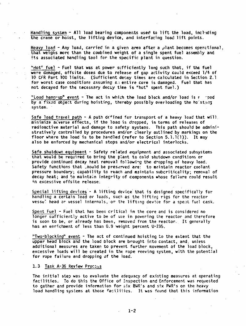
Figures 2.2-1, 2, 3, and 4, based on an infinite lattice study, illustrate theeffect of enrichment, lattice spacing, and boron concentration on k Whilethese figures are computed for Westinghouse 15 x 15 fuel, the trendf 1hownhold for all commercial fuel designs. Typical re.fueling water concentrationsare 2,000 ppm for PWR reactor cavities and storage pools, although this varies(see Seztion 2.2.5.1); and 0 ppm for BWR reactor cavities and storage pools.The following characteristics of commercial fuels are important to the presentdi scussion:
(1) As built lattice spacings in the core for all fuel designs are chosen sothat in pure water k is near the maximum value that can be attained byadjusting lattice spSIng. This can be seen in Figures 2.2-1, 2, 3, and4. where the water/uranium ratio is an indicator -if lattice spacing. PWRfLel is undermoderated in r's-e water (lattice spacing chosen to the leftof the peak) throLghouW -,ycle for both hot and cold conditions. Athigh boron concentrations, PWR fuel is highly overmoderated so thatdecreasing the lattice spacing (i.e. , reducing the water/uranium ratio bycrushing the fuel) increases keff*
(2) B)R fuel is undermoderated at hot corditions throughout the cycle; atccld conitions it is undermoderated at beginning-of-cycle and slightlyo-'ermoderated at end-of-cycle.
Because of this, decreasing the lattice spading fror its as-built value (i.e.,reduciig the water:uranium ratio by crushing the fuel) in pure water at end ofcycle bill slightly increase k (but not above 0.95 due to the low enrichmentat end-of-cycle), and at begin•|g of cycle kill cause a decrease in keff*
Approximate levels of ke~f for fuels under different conditions are shown inTables 2.2-1, 2, 3, and . Acutal numbers may vary somewhat from the numbersin tiiese tables depending on fuel desigr; the numbers in these tables aremeant c-nlv to serve as a guide to determine which fuel configurations have apotential for criticality resulting from a load drop.
The analyses of Figures 2.2-1, 2, 3, and 4 and Tables 2.2-1, 2, 3, and 4 arefor an infinite array of fuel pins with no sclid boral poison or steel oralumin.m structural material, which are also neutron poisons. Because
2-8

5..4, Parameters are as follows. (The dimersions used are t'hose
of Westinghouse 15 x 15tuel)
Fuel Pellet Diameter ................ 0-3659,Zirc Clad Inside Diameter ............. 03734"Zirc Clad Outside Diameter .............. 0A220"As-Built W/U Ratio ................ 1.647Temperature ..................... 20 DEGCFuel Material ...................... 09 w/o U2135
II I _ I I11.0
0-9
01
0.6
0.4
020.5 1.0 1.5 2.0 2.5 3-0 3.5 4.0
Water/U02 Volume Ratio (V"U Ratio) OP
FIGURE 2.2-1NEUTRON MULTIPLICATION FACTOR FOR INFINITE ARRAY OF FUEL RODS IN BORATED WATER
2-9

Parameters are as follows. (The dimensions used are thoseof Westinghouse 15 x 15 fuel)
Fuel Pellet Diameter ................ 0.3659"Zirc C i Inside Dianeter ............. 0.3734"Zirc Ckd Outside Diameter ........... 0A220"As-Bui, W/U Ratio ................ 1.647Temperature ..................... 20 OEGCFuel Material ..................... 2.0 w/o U235
-1:3
1.2
1.1
1
0.9
0.8
0.7
0.6
Vrater/U02 Volume Ratio (W!U Ratio)
FIGURE 2.2-2NEUTRON MULTIPLICATION FACTOR FOR INFINITE ARRAY OF FUEL RODS IN BORATED WATER
L-IO

Parameters are as follows. (The dimensions used are those
of Westinghouse 15 x 15 fuel)
Fuel Pellet Diameter ................ 0a3659"Zirc Clad Inside Diameter ............. 0.3734"Zirc Clad Outside Diameter ........... 0.4220"As-Built W/U Ratio ................ 1.647Temperature ...................... 20 DEGCFuel Material ..................... 3.5 v/o U235
1.4
1.3
1.2
t 1.1
1.0
0.9
0.8
0.5 1.0 1.5 2.0 2.5 3.0 3.5 4.0
Water/U02 Volume Ratio (W/U Ratio)
FIGURE 2.2-3NEUTRON MULTIPLICATION FACTOR FOR INFINITE ARRAY OF FUEL RODS IN BORATED WATER
2-.1
I
Parameters are as follows. (The dimensions used are thoseof Wes.nr•ouse 15 x 15 fuel)
Fuel Pellet Diameter ................ 0.3659"Zirc Clad Inside DiameteT ............. 0.3734"Zirc Clad Outside Diame-..r ....... .. 0.4220"As-Buift W/U Ratio ................ 1.647Temperature .......... 20 DEGCFuel Material ..................... 5.0 w/o U235
- 12
1.1
1.
0.9
Sf028
0.7
0.6
0-5
Water/U02 Volume Ra.o (WiU Ratb) 0.
FIGURE 2.2-4NEUTRON MULTIPLICATION FACTOR FOR INFINITE ARRAY OF FUEL RODS IN BORATED WATER
2-12

TABLE 2.2-1
APPROXIMATE KEFF FOR 0.9 W/O U-235 FUEL UNDER DIFFERENT ACCIDENT CONDITIONS*
Boron Concentration (ppm)Condition of Fuel and Fuel Rack
0 1000 2000 3000 4000 5000
1. Fuel •nd Fuel Rack Intact 0.40 0.36 0.30 0.20
2. Fuel Intact
Rack CrushedSo That FuelBundles Touch
OrAlternativelyCondition ofFuel in Cores
0.19 0.78 0.64 0.50 llm
-• 3. Rack and Fuel Crushedto Maximize keff 0.99 0.80 0.74 0.72
/
*0.9 i/o is typical enrichment for discharged fuel, and thus is representative of normal spent fuelpool conditions, but without boron poison plates.

TABLE 2.2-2
APPROXIMATE KEFF FOR 2.0 W/O U-235 FUEL UNDER DIFFERENT ACCIDENT CONDITIONS*
Boron Concentration (ppm)Condition of Fuel and Fuel Rack
0 1000 2000 3000 4000 5000
1. Fel and Fuel Rack Intact 0.80 0.65 0.50 0.35
2. Fuel Intact
Rack CrushedSo That Fuelnundles Touch
OrAlternativelyCondition ofFuel in Cores
1.26 1.07 0.97 0.83
3c. Rack and Fuel Crushedto Maximize keff 1.28 1.08 0.99 0.93
*2.0 w/o U-235 is a typical core average enrichment for reload cores (after reload).
ii,

TABLE 2.2-3
APPROXIMATE KEFF FOR 3.5 W/O U-235 FUEL UNDER DIFFERENT ACCIDENT CONDITIONS*
Boron Concentration (ppm)Condition of Fuel and Fuel Rack
0 1000 2000 3000 5000 7000
1. Fuel and Fuel Rack Intact 0.95 0.81 0.67 0.53
2. Fuel Intact
Rack CrushedSo That FuelBtjr'lles Touch
OrAlternativelyCondition ofFuel in Cores
1 .40 1.24 1.13 1.02 0.92 0.82
L 3. Rack and Fuel Crushedto MAxfmize k., 1.43 1.24 1.15 1. 09 1.01 0. 96
*In the past 3.5 w/o U-235 has been the fuel rack design basis enrichment. Most fuel rack analyses have beenperformed using 3.5 .w/o U-235. However, recently enrichments greater than 3.5 w/o have been used at someplants. Thus in this report we are considering enrichments up to 5.0 w/o U-235.

TABLE 2.2-4
APPROXIMATE KEF F FOR 5.0 W/O U-235 FUEL UNDER DIFFERENT ACCIDENT CONDITIONS*
Boron Concentration (ppm)Condition of Fuel and Fuel Rack
3000 5000 7000 10,000
1. rtuel and Fuel Rack Intact- -- -
2. Fuel IntactOr
Rack CrushcdSo That FuelBundles Touch
AlternativelyCondition ofFuel in Cores
1.15 1.02
1.11
0.92 0.73
Rack and Fuel Crushedto Maximize k 1.19 1.06 1.01
*5.0 w/o is maximum enrichment for new fuel, and thus is representative of worst case spent fuel
pool conditions for a limited number of assemblies in the pool.

,of this the pin cell calculations and the results in lines 2 and 3 of thesetables are at least slightly conservative for load drop conditions; for racksthat contain a large amount of boral poison, these calculations and resultsare very conservative. Line 1 of these tables is based on the fuel rackdesign basis, and is applicable to all rack designs, whether or not theycontain these neutron poisons.
The critical mass of PWR and BWR fuel in pure water is of interert in criticalityestimates, and will be noted here. For PWRs, tyoically, 2 fresh adjacent fuelassemblies constitute a critical mass. For BWRs, typically, 14 to 20 freshfuel assemblies, which always contain gadolinium poison, constitute a criticalmass. During service, the gadolinium is depleted before the uranium, andhence, the reactivity of VdR assemblies increases during the first part oftheir service life. At maximum reactivity, typically 6 BWR assembliesconstitute a critical mass.
2.2.3 Fuel Rack Design Basis
Currently, all fuel racks are designed to be subcritical under two conservativeassumptions: (1) the rack and fuel are immersed in unborated water, (2) therack is an infinite array in the x-y plane completely filled with fuel of thehighest enrichment expected to be used at the plant. In review of spent fuelpool designs, the staff requires the licensee to demonstrate, by computation,that under these assumptions the k for the spent fuel is equal to or lessthan O.S5. This computation must FAservatively account for all uncertainties.Many, but-not all, licensees have chosen to account for the uncertainties on a95%/95% confidence/probability tolerance limit basis.
In the past the highest fuel enrichments encountered were as follows: (1) PWRfuel enriched to 3.5 w/o U235, and (2) BWR fuel enriched to give a k of1.35 for an array of adjacent fuel assemblies. However, with the introductionof new fuel management schemes, some PWR licensees are using fuel enrichmentsas high as .4.2 w/o U235, and in the future we may see even higher enrichments.For those licensees using the more highly enriched fuel, the fuel rack designbasis should be changed tc reflect the actual enrichments used.
The criticality calculatiens for rack designs are performed using combinationsof diffusion codes, transport codes, and Monte Carlo codes. All calculationalmodels are benchmarked against critical experiments.
2.2.3.1 Standard Rack Designs
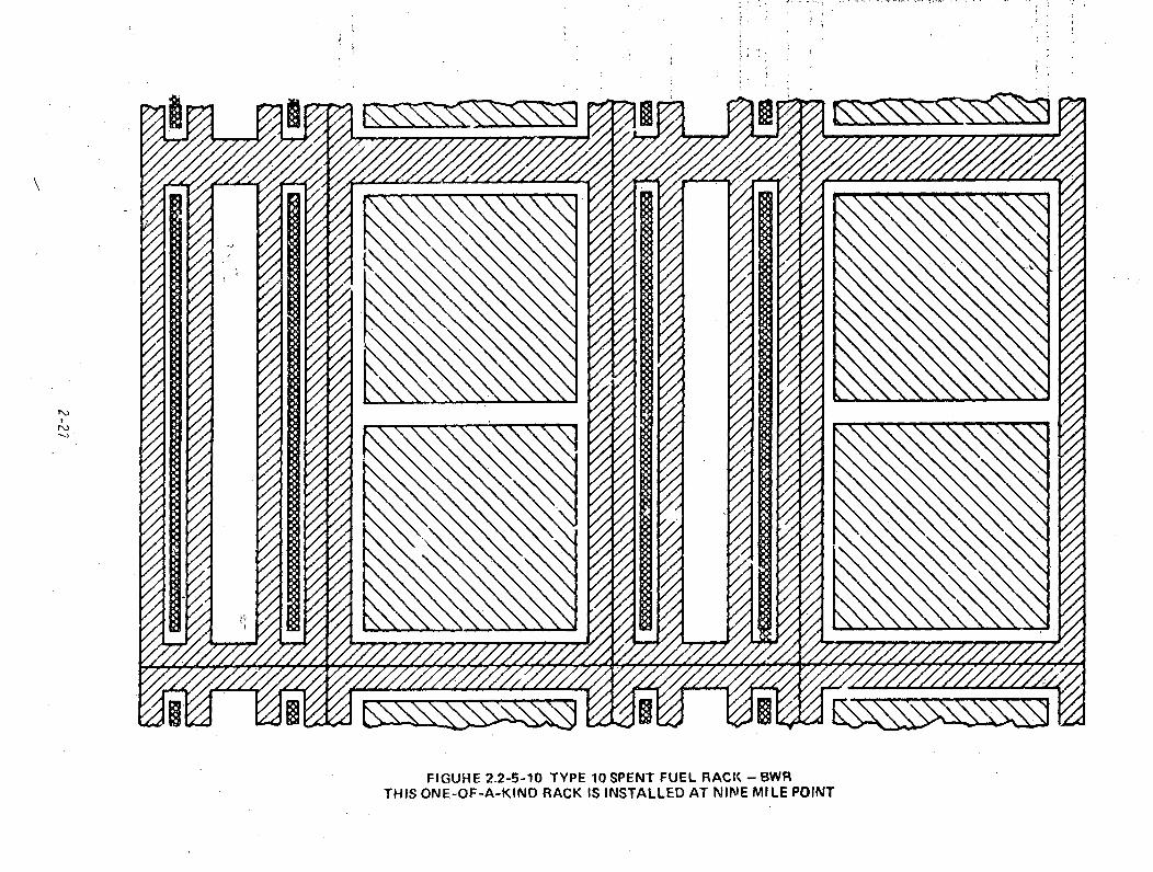
The geometrical details of fuel rack designs in use as of thiE writing areillustrated in Figures 2.2-5-1 through 2.2-5-11. These are arbitrarilylabeled Type 1 through Type 11 for the purposes of this report. The legendfor these figures is giver in Figure 2.2-5-12. Types I through 5 are for PWRfuel and Types 6 through 11 are for BWR fuel. Some rack types are one-of-a-kindor several-of-a-kind, and this is indicated in the figures. These figures arenot drawn to scale, but rather the steel, aluminum, and boral are drawn thickerthan as-built for ease in illustration.
2-17

-J
FIGURE 2.2-5-1 TYPE 1 SPENT FUEL RACK - PWR

Af
r.3I-
I - - - - - - - - - - - - - - -
I,
/0
,J-4
/
FIGURE 2.2-5-2 TYPE 2 SPENT FUEL RACK - PWR

r,,3
#1,
FIGURE 2.2-5-3 TYPE 3 SPENT FUEL RACK,- PWR

.. -1, - l-?-.l--v,--.r-ý-,--,.
/
,0
/'
r'o).0.p
,/~ /
//
)
1Z/1
. ~ ~ --A, - -
FIGURE 2.2-5-4 TYPE 4 SPENT FUEL RACK - PWRTHIS ONE-OF-A-KIND RACK IS INSTALLED AT POINT BEACH

Z-•2X777½7•"
/
/IN
FIGURE 2.2-5-5 TYPE 5 SPENT FUEL RACK - PWRTHIS ONE-OF-A-KIND RACK IS INSTALLED AT GINNA

FIGURE 2 2-5-6 TYPE 6 SPENT FUEL RACK - BWR

V,.
FIGUfE 2.2-5-7 TYPE 7 SPENT FUEL RACK - BWR

I
/0
!2kY "IfY00
/-1i0
"of
/ FIGURE 2.2-5-8 TYPE 8 SPENT FUEL RACK - BWR
THIS TWO-OF -A-KINQ RACK IS INSTALLED AT OYSTER CREEK AND NINE MILE POINT

FIGURE 2.2-5-9 TYPE 9 SPENT FUEL RACK - BWRTHIS TWO-OF-A-KIND RACK IS INSTALLED AT DRESDEN 1 AND QUAD CITIES 1 & 2.
/
//
'o,
x
ýo
oo,-
Is,
N)
N)
ra -- - - - - - - - - - - - - -
V'AYYA -/Z
FIGURE 2.2-5-10 TYPE 10 SPENT FUEL RACK -,BWRTHIS ONE-OF-A-KIND RACK IS INSTALLED AT NINE MILE POINT

i ''
FIGURE 2.2-5-11 TYPE 11 SPENT FUEL RACK BWR
THIS ONE-or-A-KIND RACK IS INSTALLED AT COOPER

Fuel Steel Aluminum Boral
Assembly
FIGURE 2.2-5-12 LEGEND FOR FIGURES 2.2-5-1 THRU 2.2-5-11

2.2.4 Potential for Crit~cality of BWR Fuel
2.2.4.1 BWR Spent Fuel Rack Design
The new high density BWR racks are composed of arrays of cans containing boralneutron poison. The spent fuel pools are filled with unborated water, ratherthan borated water, as is the case with the PWR ipent fuel pool!;. Most BWOlicensees demonstrate for these racks a k of about 0.86 for fuel in theracks which would have a k of 1.35 in fure water in the reactor core lattic.with Ute control rods remo$4.
BWR spent fuel racks of type 8 and 9, both of which are two-of-a-kind rack-,and type 10, which is a one-of-a-kind rvk depend almost entirely on fuelseparation to maintain the fuel subcritical, and contain no boral poison. Forthese racks, however, there is some neutron absorption in the steel or aluminiumof the racks themselves, which aides somewhat in maintaining the fuel subcritical.
2.2.4.2 Potential for Criticality in A 8WR Spent Fuel Pool
First we will discuss the case of racks with boral poison cans. As noted inSection 2.2.2(l), crushing the BWR fuel assemblies would not significantlyincrease the kff of the fuel. For racks with boral poison, it seemsinconceivable Mat any load which might fall on the spent fuel pool wouldseparate the fue- from tho poison cans aid subsequently push the assembliestogether to form a critical mass. Therefore it appears that postulated loaddrop events would not cause a criticality in a BWR spent fuel pool that usesboron plate can type racks.
For those spent fuel pools which depend on fuel separation to preventcriticality, that is type 8, 9, and 10 spent fuel racks, the drop of a heavyload which crushes the fuel rack would substa~ntially raise k If severalhighly enriched fuels were stored in the region of the pool w re the load isdropped, a criticality could result. Adjitionally, these types of fuel rackshave separation in only one direction, aid hence crushing the rack by a heavyload drop is more likely to result in an optimum configuration for increasingk than racks which have separation in two directions, such as certain PWR
2.2.4.3 Potential Criticality of BWR Reactor Core Due to A Heavy Load Drop
At least three heavy loads are carried over the core during refueling, namelythe steam dryer (20-40 tons), the moisture separator (20-75 tons), and thevessel head (45-96 tons). These are carried over the core before and afterrefueling. These "before" and "after" cases will be discussed separately.
BWR Technical Specificaticns typically require that during refueling, with themost reactive control rod out of the core, k shall be no greater than0.997. During refueling, single control rod• lust be withdrawn, so that ak of 0.997 actually may occur. However, before and after refueling, whentgTheavy loads are carried over the core, all control rods are inserted, andk is no greater than about 0.96. The k & of 0.96 would be attained onlyaX r the core is reloaded. Before relo-dih•, keff would be significantlyless than this, probably no greater than 0.90.
2-3-r

After Reload: For this case, k is no greater than abkut.O.96. Since t 'e "core is undermoderated, crushin• the core will decrease k Thus, it appearsthere is no possibility of driving the core critical by cJuFhing it in theafter-reload case.
Before Reload: For this case, k is no greater than about 0.90. The coreis overmoderated, but crushing cdnfonly increase k ft by a fraction of onepercent. Thus it is not possible to drive the corS ritical by crushing itfor the before-reload case.
The reactor is kept subcritical during refueling by the presence of cruciformcontrol rods which are inserted from the bottom of the core. If a heavy loadwere to fall on the core and drive these rods out of the core (either before,
-during, or after reload), the core would immediately become supercritical.The potential for the load to drive the rods out of the core is small due to:the absorption of energy by deformation of fuel and control rods, more likelycontrol rod failure modes than driving rods out of the core, and the catcherassembly below the control rod drives. However, information available to thestaff was not sufficient to rule out this failure mechanism as a credibleevent. Guidelines contained in Section 5.1.4 and Appendix A requireconsideration of this mechanism.
2.2.5 Potential for Criticality of PWR Fuel
2.2.5.1 PWR Fuel Rack Designs
PWR fuel racks are maintainwd subcritical by employing three mechanisms:separation, steel neutron poison, and boron neutron poison plates. While thedesign analysis is performed assuming the spent fuel pool is filled withunborated water, in actuality the spent fuel water is borated to about2000 ppm.
While the spent fuel pool boron concentration is typically not specified by alicensing requirement, the refueling water boron concentrations are delineatedin all PWR Technical Specifications, and in all cases the spent fuel poolboron concentration will be very nearly or exactly the same as that of therefueling water. No credit is taken for the boron in demonstrating thesubcriticality of the spent fuel pool under normal storage conditions.Required refueling water concentrations range from 1700 ppm to 2300 ppm boronconcentraLion, depending on the plant. One notable exception to this is SalOnofre Unit No. 1, for which the required boron concentration is 3750 ppm cn4300 ppm boron concentration.
2.2.5.2 Potential for Criticality in A PWR Spent Fuel Pool
It is apparent from Tables 2.2-2, 3, and 4 that under conditions where anaccidental load drop crushes fuel from an offload core, it may be necessary totake credit for the borated spent fuel pool water to demonstrate subcriticality.
However, it appears from Tables 2.?-2, 3, and 4 that the 1700 ppm to 2300 ppmboron concentrat.on normally maintained in the storage pools may not bc ade;uateto guarantee subcriticality of a large array of fresh or partially burned fueluider load drop accident conditions. Subcriticality could be maintained by
2-31

providing an Increased boron concentration. It should be noted that theresults shown in Tables 2.2-2, 3, and 4 were computed without taking creditfor the neutron absorbing effects of the boral poison in the fuel racks or thestructural aluminum or steel. Some racks rely heavily on' the presence ofthese absorbers to maintain the fuel in a subcritical condition, while otherracks rely principally on fuel separation to maintain the fuel subcritical.For those racks which rely principally on separation. the values in Tables 2.2-2,3, and4 could be reasonably conservative for load dop accident conditions.For racks which contain a large amount of solid neutron absorber, under loaddrýp accident conditions we can expect keff to be significantly lower than isindicated by the tables.
It should be noted that the above conclusions may be somewhat conservativebecause they are based on criticality calculations which assume an infinitearray of highly enriched fuel. Generally, criticality calculations based onmore real-istic amounts of highly enriched fuel predict substantially lowerrequired boron concentrations.
Additionally, it is possible that the drop of a heavy load could puncture thespent fuel pool liner. Normally, for PWR spent fuel pools, the borated refuelingwater can be pumped directly into the spent fuel pool to make up for leakage.If the leakage is so great that the reserve of borated water is exhausted, itwould be necessary to fill the pool with unborated water from whatever sourcemight be available. If such an accident also crushed the fuel rack to bring alarge amount of highly enriched fuel together, then a criticality would ensuedue to boron dilution. The potential for damage to the pool liner due to anaccidental load drop is further discussed in Section 2.3.
2.2.5.3 Potential Criticality of A PWR Reactor Core Due to Heavy Load Drop
There are two load drop mechanisms which could cause a criticality of the coreduring refueling.
(1) The reactor vessel could be damaged and the borated refueling waterbackup exhausted, resulting in criticality due to boron dilution whenmakeup is su-plied from an unborated source.
(2) The fuel could be compacted to a critical configuration in the 2000-ppmrefueling water.
The potential for damage to the reactor vessel due to a load drop is discussedfurther in Section 2.3.
With respect to the potential for fuel to be crushed to a compact configuration,the data from Table 2.2-2 at 2.0 w/o U235 may be used to -epresent effects ora reload core. At 2000 ppm, the worst case analyzed here gives a whole corek of 0.99. The control rods, which are in the core du-ing refueling, anda• 'not considered in Table 2.2-2, have a reactivity worth'of- about 10%. Thiswould bring the k - down to about 0.89. Reload core average enrichnentsrange from about 21 w/o U235 to 2.4 w/o U235. The difference of 0.4 w/o U235has a reactivity worth of, at most, 0.06. This would bring Kff upto approxi-mately 0.95. Thus, assuming about a 5% uncertainty onthe abS3 analysis, themaximum keff of a reactor core under load drop conditions ranges from about
2-32

0.85 to 1.00. These figures do. not rule out the possibility that a PWR corecould-become critical under the worst postulated load drop conditions. FromTable 2.2-2 it seems that for the worst postulated load drop conditions, thecore could be maintained subcritcal if boron concentration is maintained above2500 ppm.
The above discussed the potential for criticality usin- an average cor, enrich-ment value. However, some h-gher enrichment assemblies are located in thecore. At appears unlikely t!hat crushing the more highly enriched assemblieslocated around the perimeter of the core (i.e., 3.5 w/o) could result in alocalized criticality. The cores are always designed to produce a flat powerdistrbution, with the highly enriched assemblies placed in positions where the'.-_•-ron leakag2 is high. In fact, because of this leakage, the highly enriched,.-sh fue, assemblies are normally the lowpower assemblies in the core. InTables 2. :--2 ind 2.2-3, it can be seen that for both the core average assembliesanC q;-hc .. , U--?35 assemblies, optimal cruchiýig increases the reactivity byabout 2%. Ytws, crushing is not expected to drive the local k .f in thehiuhly enrich.d aýsemblies significantly above the keff for th~w~hole core.
2.2.6 ( ncpsis of Potential Criticality Situations
In t.fe r:. *-- "hs we have discussed the potential for criticality inthe eCvr: .d drop in some detail. We will here give a summary of.he.r fic- i J,-
For the_-. - ig cases there appears to be no potential for criticality dueto a heev.> Irop:
(1) BWR s-ent fuel racks made up of a compact array of cans with boron plates;(2) A BWP core, if it is postulated that the drop of a heavy load will not
drive the control rods out of the core.(3) A BWR or PWR spent fuel pool which contains only totally spent fuel.
A low potential for criticality exists in the following cases:
(1) A PWR reactor core if crushed due to a heavy load drop.(2) PWR and BWR spent fuel racks which contain some neutron poison, but still
depend on fuel separation• to maintain the fuel subcritical. These wouldonly be a problem if crushed and if they containea non-spent fuel.(Note: All PWR racks dEpend to some extent on separation, BWR racks mayor may not depend on separation).
A high potential for criticality exists in the following cases:
(1) A BWR core if the heavy load were to drive the control r.ýs out of thecore, although the probability of this failure mode is considered small.
(2) PWR and BWR spent fuel racks -which have no boral poison, but depend onfuel separation to maintain the fuel subcritical. This would only be aproblem if they were crushed and if the, contained non-spent fuel such asan off-load core.
2-33

2.3 Safe Shutdown Equipment
Loads may be carried in the area of safe shutdown equipment when the plant isoperating. If these loads experienced uncontrolled movement or were droppedon safe shutdown equipment, the equipment may be unable to perform its function.The safe shutdown equipment includes items such as cabling, pumps, instrumentracks, the control room, switchgear, and piping required to attain and maintaina safe-shutdown. The loads could include various plant equipment, such asmotors, pumps, valves, heat exchangers, switchgear, turbine equipment, andshielded shipping casks.
An example of the above is the handling of the shielded spent fuel cask in aBWR. The cask may be carried into the reactor building on a rail transporteror truck flatbed, and then unloaded and hoisted from grade elevation vertically90 feet (27 m) to the refueling floor level. If a "two-blocking" event wereto occur during this lift, a load drop in excess of 90 feet (27 m) couldresult. At some BWR's, this cask lift takes place over the suppression poolor a corner room which may contain residual heat removal (RHR), core spray, orreactor core isolation cooling (RCIC) pumps and equipment. It is generallyacknowledged the intervening floor can not withstand a cask drop from such anelevation. The exact equipment that may be damaged in such a postulated eventwill depended on the specific plant layout and the location(s) where the dropis postulated to occur. If equipment from only one sifety division, or safeshutdown path, is damaged, safe shutdown could generally be effected usingequipment from the alternate or redundant shutdown path.
The potential for load drops to damage equipment from both safe shutdown pathswill depend on plant layout and potential load paths. However, for mostplants, redundant or dual equipment is already well separated due to othersafety concerns such as protection against flooding, missiles, pipe whip,electrical f-jlting, and fire protection. Despite measures taken for theseconcerns, areas may still exist, particularly at older facilities, whereredundant safe shutdown equipment are located in the same area or in separateareas but still within the path of a. fallng load.
Pool and Vessel Water Inventory
The reactor vessel head may weigh 55-165 tons (50,000-150,000 kg) and may be-hoisted 20-50 feet (6-15 r) above the vessel flange. During the refuelingoperations, a drop of the reactor vessel head could impact the vessel flange.Since PWR vessels are typically supported by the vessel nozzles and refuelingtakes place when the vessel is cold and possibly below the NDTT (nil-ductilitytransition temperature; i.e. , part of the vessel is in the brittle :racturerange), a load drop having sufficient kinetic energy may potentially result indamage to the vessel nozzles or piping and cause loss of water inventory.Damage to only the nozzles or to piping would not in itself uncover the core;however, the possible lack of makeup water along with the boil-off due todecay heat could lead to uncovering of the-core and subsequent fuel damage andrelease of fission products. Additionally, it appears that a postulated loaddrop of the vessel head could potentially damage the vessel itself in eitnerBWRs or PWRs, and lead to uncovering the fuel if sufficient leakage resultedbeyond water makeup capability.
2-34

Similarly, a load drop of the spcnt fuel cask in the spent fuel storage areacould potentially result in dama(,e to the spent fuel pool liner and structure,causing -leakage of inventory. E.cessive 2akage beyond water makeup capabilitycould lead to uncovering of the fuel with subsequent fuel damage and releaseof fission products.
2-35

3. SURVEY OF LICENSEE INFORMATION
In response to the staff's generic letter of June 12, 1978, licensees submittedvarious details related to load handling operations at their facilities. Thisinformation included:
(]1) Identification of heavy loads and frequency of movement over or nearspent fuel in the storage pool or fuel in the reactor;
(2) Identification of Inad paths normally followed in handling these heavyloads;
(3) Description of procedures developed relative to handling of heavy loads;(4) Identification of certain analyses performed relative to a heavy load
drop, such as cask drop analyses;(5) Identification of certain design features which preclude a heavy load
drop, such as a single-failure-proof crane;(6) Identification of certain safety systems over which heavy loads may be
handled; and(7) Identification of conformance to Regulatory Guide 1.13, namely whether a
single failure proof crane is provided, the spent fuel pool is desicnedto withstand a cask drop, or loads are precluded from being brought overthe spent fuel pool by crane design.
The following sections provide a summary of the information submitted, indicatingthe types of heavy loads that are handled and the measures already in effectwhich prevent, or mitigate the consequences of, accidental load drops.
In general, information in this Section does not includs plants in the SystematicEvaluation Program (SEP) because at the time this generic letter was sent tolicensees, the staff was planning to have the SEP Program resolve this issuefor SEP plants. The staff has since decided that implementation of guidelinescontained in this report will be carried out for all operating plants, includincSEP plants.
3.1 Heavy Loads
Information subnitteA ¶y licensees was reviewed to identify the types oa heavyloads that are handled, and their frequency of movements, over or in proximityto spent fuel or safe shutdown equipment. Table 3.1-1 provides a summary oftypical loads handled, frequency of movement, and range of weight of theloads. The following are significant points to be noted from Table 3.1-1:
(1) PWR - Refueling Building
(a) There are a large number of heavy loads that may be carried inproximity to spent fuel, but for many plants, heavy loads need notbe brought over spent fuel in the pool. This means that measures,such as the installation of mechanical stops or electrical interlocks,can be taken to preclude loads from being brought over spent fuel.
(b) Despite this, some loads such as the spent fuel shipping cask andpool gates may have to be brought over or near the spent fuel pool,although not over spent fuel.
(c) Certain plants may have to bring heavy loads over or in proximity tospent fuel.
3-1

TABLE 3.1-1
SURVEY OF HEAVY LOADS
:A)Ir•
Over (0) or OnlyProximity (P) to Approx. 1 / Fvequency
Area Loads Handled Fuel Weight. - Handled
1. PWR -Refueling 1. Spent Fuel Shipping Cask (P) 15-110 Tons 2/
Building (13-100,000 kg)2. Pool Divider Gates (some plants) (P) 2 Tons 2-4 x's (per
(1800 kg) refueling)
3. Fuel Transfer Canal Door (P) 2 Tons 2-4 x's (per(1800 kg) refueling)
4. Missile Shields (P) 4-20 Tons 2 x's (per(4-19,000 kg) refueling)
5. Irradiated Specimen Shipping (P) 3.5-12 Tons Once per year toCask (3-11,000 kg) once per 10 years
6. Plant Equipment (some plants) (0) 2-4 Tons As required for(o.g,. purmp;, motors, valves, (1800-3600 kg) modification orheat exchangers, etý..) replacement
7. Spent resin, filter, or other (P) 5-37 Tons ~ 5 x's per yearradioactive material shipping (4500-33,000 kg)casks
8. New fuel shipping containers (P) 3-4 Tons V
with fuel (usually 4 assemblies) (2700-3300 kg)
9. Failed Fuel Container (0) 1 Ton Less than once(900 kg) per refueling

TABLE 3.1-1 (Continued)
Over (0) or OnlyProximity (P) to Approx. Frequency
Area Loads Handled Fw'l Weights' Haidled
1. (cont, ) 10. Fuel transfer carriage
11. Crane Load Block
1. Reactor Vetsel Head
(0) or (P) 1.5 Tons(1300 kg)
Only for main-tenance or repair(7 once per 10 years)
1/
2. PWR - ContainmentBuilding
2. Upper Internals
(-3. In-Service Inspection Tool
4. Reactor Coolant Pump
5. Missile Shields
(0)
(0)
(0)
(0)
(P)
(P)
(0)
(P)
(P)
4-10 Tons(4-9,000 kg)
55-165 Tons(50-150,000 kg)
25-65 Tons(23-33,000 kg)
4.5 Tons(4,000 kg)
30-40 Tons(27-36,000 kg)
10-20 Tons(9-18,000 kg)
4-10 Tons(4-9,000 kg)
15-125 Tons(13-112,000 kg)
45-85 Tons(40-77,000 kg)
2 x's (perrefueling)
Used at least onceevery three years
4-10 x's overlife of plant
2 x's (per
refueling)
1/
2 x's (perrefueling)
6. Crane Load Block
3. BWR-- ReactorBtui lding.
1. Missile or Shield Plugs (6-12) 2 x's (perrefueling)
2 x's (perrefueling)
2. Drywell Head

TABLE 3.1-1 (Continued)
Over (0) or OnlyProximity (P) to
FuelApprox.Weights-
FrequencyHandledArea Loads Handled
3. (cont.) 3. Reactor Vessel Head
4. Steam Dryers-
5. Moisture Separators-/
6. Spent Fuel Pool Gates
7. Dryer/Separator Storage PitShield Plugs (some plants)
8. Refueling Slot Plugs
9. Spent Fuel Shipping.Cask
10. Vessel Service Platform
11. Waste and Debris ShippingCasks
(0) (Overreactor)
(0) (OverroRctor)
(0) (Overreactor)
(0) (Overspent fuelpool)
45-96 Ton%(40-86,000 kg)
20-40.Tons(IR-36,000 kg)
20-75 Tons(18-68,000 kg)
2-6 Tons(1800-5,000 kg)
2 xmq (parrefueling)
2 x's (perrofol IIng)
2 x's (perrefueling)
2 x's (perrefueling)
2 x's (perrefueling)
2 x's (perrefueling)
(P) 75 Tons(68,000 kg)
(0) (Overspent fuelpool)
(0) (Overspent fuelpool)
2-6 Tons(1800-5400 kg)
15-110 Tons(14-99,000 kg)
1-5 Tons(900-4500 kg)
4/
(0) 5-10 x's (perrefueli.ng)
1-3 x's, (peryear)
(0) (Overreactor and/or spent fuelpool)
8-30 Tons(7-27,000 kg)

TABLE 3.1-1 (Continued)
Over (0) or OnlyProximity (P) to Approx..i/ Frequency
Area Loads Handled Fuel Weight - Handled
3. (cont. ) 12. Vpssel HPAd Tnsulation
13. Replacement Fuel StorageRacks for Spent Fuel
(P)
(0) (Overspent fuel)
14. Crane Load Block
15. Plant Equipment
(0)
4. Other Plant* Areas
1. Spent Fuel Shipping Casks(some plants)
2. Turbine or other equipmentin turbine huilding (someplants)
3. Other plant equipment (pumps,motor5, valves, heat exchangers,etc.)
(0) (Oversafety equip.)
(0) (Oversafety equip-ment)
(0) (Over)safety equip-ment)
(0) (Oversafety equip-ment)
4-6 Tona(4-5,000 kg)
8 Tons(7,000 kq)
4-10 Tons(4-9,000 kg)
1 Ton(900 kg)
15-110 Tons(14-99,000 kg)
2-150 Tons(2-135,000 kg)
1-30 Tons(1-27,000 kg)
1/
2 x'a (perrefueling)
2/, 4/
On installation
As requiredfor equipmentoverhaul andreplacement
As required forequipment overhauland rep1acement

*TABLE 3.1-1
FOOTNOTES
/ 'Listed weight for loads does not include weight of load block exceptwhere listed separately. The load block may add 4-10 tons (4,000 -9,000 kg) to the weight of the dropped load. Because of this, the loadblock should be coasidered a heavy load even if it is not carrying aload, or is being used with a lighter load.
2/ These are presently not being used at most plants. However, once offsite
waste repositories are established, casks will be used frequently forshipping spent fuel offsite. For a typical 1,000 MWe pressurized waterreactor, spent fuel casks must be shipped offsite fror 7 to 65 times peryear depending on the size cask used. This is based on casks currentlylicensed for use in the United States.
A typical 1,000 MWe power plant would usually require 16 or 17 new fuelcontainers (four fuel assemblies each) per year.
These are presently not being used at most plants. H wever, once offsitewaste repositories are established, casks will be used frequently forshipping spent fuel offsite. For a typical 1,000 MWE boiling water
actor, spent fuel casks must be shipped offs,*.- frori 12 to 125 timesper year depending on the size cask used. Thib is based on casks currentlylicensed for use in the United States.
Due to certain dimensional restrictions, for most BWR's it would not bepossible to drop the dryers or moisture separators onto fuel in thereactor core.
3-6

(2) PWR -Containment Building
(a) All plants have to carry t.e reactor vessel head and vessel internalsover the reactor vessel an! core. Further, periodically otherinspection or maintenance equipment will be handled over the reactorvessel.
(b) Certain other loads would mortrally be carried in proximity to thereactor, and if properly czntrolled, would not be brought over thereactor vessel or core.
(3) BWR - Reactor Building
(a) As in the PWR Containment Building, there are a number of heavyloads such as the vessel head, steam dryers, and moisture separatorsthat would have to be move! over or in close proximity to the reactorvessel and core. Further, other inspection and maintenance equipmentwill be periodically handled over the reactor vessel.
(b) Certain heavy loads at most plants would have to be brougnt over thespent fuel pool but not over spent fuel if properly handled,such asrefueling slot plugs, spen: fuel pool gates, spent fuel shippingcask, and shielded radioactive waste and debris shipping casks.
(c) There are a number of loads that would normally be carried in proximityto the reactor vessel and spent fuel pool. If properly handled,these would not be moved oier or in close proximity to fuel in thecore or in the spent fuel pool.
(d) The reactor building contains equipment for safe shutdown systems.Heavy loads, such as the scent fuel shipping cask or plant equipment,may be carried over safe shiutdown equipment in the reactor building.
(4) Other Plant Areas
There are a number of heavy loe~s which, if not properly controlled,could be brought over safe shutiown equipment.
Additionally, once offsite waste re2.:sitzries are established, there will befrequent handling of spent fuel ship-ing casks. The frequency will depend onthe size of the plant and the size s*iipping cask to be used. Because cf this,the frequency of movement could vary frc,- only five to over 100 shipments peryear. It should be noted that if ore of the larger casks were used by acertain facility, this would mean fewer offsite shipments; however, due to thelarger size of the cask, the destru:tive forces developed by a postulated loaddrop may result in more damage to fLel a3semblies as well as to safe shutdownequipment. The size of cask that ;i be used will also be limited by cranecapacity, rail capacity serving the Facility, and physiLal space available formovement of the cask.
3.2 Present-Protection
The types of measures presently provided at operating plants to prevent ormitigate the consequences of accidertal load drops varies considerably. Thefollowing 'sections describe the resLits Of our survey of licensee informationto identify such measures.
3-7

3.2.1 Technical Specifications
Most plants have technical specification requirements that pertain to thehandling of heavy loads. Additionally, Standard Technical Specificationsinclude a specification that prohibits travel of load5 in excess of the nominalweight of a single fuel assembly over fuel assemblies in the storage pool.Twenty-seven plants (Table 3.2-1) do not have such a specification. However,fourteen of these plants include design features such as interlocks or single-failure-proof crane design to preclude a heavy load froa. dropping on spentfuel. Thur, heavy loads could be carried over fuel assemblies in the storagepools of fourteen of these plants. This table includes plants in the SystematicEvaluation Program (SEP).
Several plants have a technical specification that prohibits movement of thespent fuel cask over the spent fuel pool. However, as noted in Table 3.2-1,such a specification doe.s not prohibit other heavy loads from being carriedover the spent fuel pool such as spent fuel pool ga-tes, refueling slot plugs,waste and debris shipping casks, plant equipment, fuel transfer carriage, orjust the crane load block without a load. Therefore, a specification thatrestricts movement of only the cask is not adequate to restrict other heavyloads from being carried over fuel assemblies in the storage pool.
3.2.2 Load Handling Procedures
Several plants have procedures related to the handling of heavy loads as shownin Table 3.2-2, for activities such as crane operation, refueling, handling ofreactor components, or cask handling. However, a large number of plantsapparently do not have such orocedurcs.
Additionally, very few plants (3 out cf 54) have procedures related to training
of crane operators.
3.2.3 Crane Design
The survey included 54 non-SEP operating reactors comprised of 36 PWRs and 18BWRs. Each of the 36 PWPs had its own individual polar crane to serve thereactor vessel within containment. By sharing the rectilinccr cranes betweentwo reactors at 10 PWR sites, the total number of PWR spent fuel cask handlingrectilinear cranes was 26. Therefore, a total of 62 polar and rectilinearcranes were instelled at the 36 PWR reactors for handling heavy loads over ornear the reactor vessel or storage pool. Due to the difference in plantlayout at the 18 BWR reactors, one rectilinear crane is capable of servicingboth the reactor vessel and associated spent fuel pool. Further, at one BWRsite, one rectilinear crane was able to meet the load handling requirements ofthree reactors and their associated spent fuel pools. At another BWR site thesingle rectilinear crane serves two reactors and associated spent fuel pools.Therefore, the 18 BWR reactors included in the review required a total of only15 rectilinear cranes. At two of the reviewed BWR sites, the rectilinearcrane also served other reactors not included in the survey, i.e., an SEPreactor and a reactor which was not included in the survey because it had notbecome operational at the time the questionnaire was sent out. Consequently,the 15 rectilinear cranes actually served the load handling requirements of20 reactors and associated pools.
3-8

TABLE 3.2-1
TECHNICAL SPECIFICATIONS PROHIBITINGHEAVY LOADS OVER STORAGE POOL
Flants that do not have a Technical Specification prohibiting handling of heavyloads over spent fuel (i.e., greater than a fuel assembly plus handling tool):
NOTES
Big Rock PointBrowns Ferry 1 - 3
Cooper
Dresden 1Dresden 2 and 3Duane ArnoldFt. Calhoun
FitzPatrickH. B. RobinsonHatch 1Haddam NeckIndian Point 2Millstone 1MonticelloNine Mile PointOyster CreekPalisadesPilgrimMaine YankeeQuad Cities I and 2Turkey Point 3 and 4Vermont Yankee
single-failure-proof crane
Limit switches to preventtravel over spent fuel
single-failure-proof crane/
electric interlocks to preventtravel over spent fuel
single-failure-proof cranesingle-failure-proof crane1/
single-failure-proof cranesingle-failure-proof crane
single-failure-proof I/crane-
single-failure-proof cranel/
1/These facilities have technical specifications that prohibit handlingof the spent fuel cask over the spent fuel pool, but do not prohibitheavy loads other than the cask from being brought over spent fuel.
3-9

TABLE 3.2-2
SURVEY OF PROCEDURES IN EFFECTRELATED TO CONTROL OF HEAVY LOADS
1.
2.
3.
4.
5.
Procedures on crane operation
Refueling procedures
Movement of reactor componentsduring or prior to refue",ing
Cask handling operations
Crane operator training
PLANTS WHICHHAVE SUCH 1 ,
PROCEDURES-
34
30
27
22
3
PLANTS WHICHAPPARENTLY
DO NOTHAVE SUCH^2
PROCEDURES-
20
24
27
32
51
'In some cases procedures were not submitted, but were referenced by titleand/or description.
-/Information provided by licensees did not indicate that such procedureswere in use.
3-10
Our review shows, as indicated in Table 3.2-Z, that the intent of NUREG-0554,"Single-Failure-Proof Cranes for Nuclear Power Plants," was:
(1) not met by any of the 36 PWR polar cranes,(2) not met in 24 of the 26 PWR rectilinear cranes (however, two licensees
have committed to upgrade a total of two cranes serving three plants tomeet single-failure-proof criteria),
(3) not met by 5 of the 15 BWR rectilinear cranes. (None of these 5 cranesserved more than one reactor); and
(4) apparently met by the remaining 10 BWR rectilinear cranes. (At one sit4where the rectilinear crane served 3 reactors, the utility made crant.modifications in order to make it single-failure-proof, however the staffhas not evaluated these modifications.) Further there are three othersites where the crane serves more than one reactor and associated spentfuel pool, i.e., one case where two reactors in the survey share onecrane, one case where one of the two reactors was not included in thesurvey because it was not operational when the questionnaire was sentout, and one case where the crane is shared between an SEP plant and areactor included in the survey. Thus, the 10 single-failure-proof BWRcranes serve 13 reactors included in the survey, or 15 reactors countingthe SEP plant and the plant which became operational recently.
3.2.4 Other Design Features
In addition to the use of a single-failure-proof crane, various other designfeatures are used in operating plants as shown in Table 3.2-4. For example,the spent fuel pool areas of 51 of the 54 operating plants included in thesurvey are enclosed, exhausted through charcoal filters, and have ventilationsystems that maintain the area at a lower pressure than the outside area sothat leakage is into the area. Such a feature will reduce the quantity ofairborne radioactive iodines released to the environment, as discussed inSection 2.1. These filters, however, are not effective in removing noblegases such as kryptons and xenons, which contribute to the whole body dose.
Approxinately one-half of the operating plants have spent fuel pools that aredesigned for their assuned cask drop, so that leakage that may result from acask drop is not sufficient to cause uncovering of spent fuel. Some of thespent fuel pools for the remaining operating plants may be able to withstand acask' drop even though they were not originally designed to have this capability.
Fewer than one-half of the operating PWR plants have rapid containment isolationon a high radiation sigrrl (16 of 36 PWRs). Such a feature reduces offsitedose that may result fromn dropping of a heavy load on spent fuel although thesize of the release will depend on the response time of this system. As aresult of the staff's review of the containment purge system; the balance ofthe PWRs will have this capability, although it may not be automatic duringthe refueling mode. (See "Containment Building-PWR" Guidelines, Section 5.1.3.)
According to licensee responses, 39 of 54 operating plants have a spent fuelpool that is apparently designed to comply with Regulatory Guide 1.13. Thismeans that such plants either have a single failure proof crane, a pool designed,to withstand a cask drop without experienceing excessive leakage, electricalinterlocks to prevent heavy loads from being carried over the spent fuel pool,
3-11

TABLE 3.2-3
CRANES SATISFYING INTENT OFNUREG 0554-SlNGLE FAILURE PROOF CRANE-1
Satisfy NUREG-0554# Plants # Cranes
Do Not Satisfy NUREG-0554# Plants # Cranes
PWR: Containment Polar CraneRefueling Building Crane
BWR: Reactor Building Crane
02
13
02
362!34-.-
36224-_
10
Fifty-four_(54) reactors were covered i;, the survey. Not included were eleven (11)
SEP plants, two (2) plants indefinitely out of service, two (2) plants which wererecently licensed, and Ft. St. Vrain which is a Gas-Cooled Reactor and the surveywas limited to water reactors (there were 70 plants licensed to operate as ofSeptember 1979).
-/However, licensees of three (3) of these plants have committed to upgrade thecranes used to handle the cask (affects two (2) cranes), although no date forcompletion of this upgrading has been established.
-/However, one BWR licensee has committed to upgrade the reactor twilding crane.
3-12

TABLE 3.2-4
SURVEY OF DESIGN FEATURES
RELATED TO CONTROL
OF HEAVY LOADS"1
PLANTS THAT
HAVE THI1
DESIGN FEATURE
PLANTS WITHOUT
THIS
DESIGN FEATURE
Containment (Spent Fuel Pool Area)
Charcoal Filters (Spent Fuel Pool Area)
Pool Designed for Their Assuxed Cask D-'-p
Containment Isolation on High
Radiation (PWR)
Compliance with Regulatory
Guide 1.13
51
51
26
3
3
28
20
39
- Exclusive of crane features covered by Table 3.2-3.
-2/PWR plants that have rapid containment isolation on high radiation:
D.C. Cook 1 & 2 Prairie island I & 2
Ft. Calhoun Rancho Seco
Farley Salem 1
Maine Yankee Turkey Point 3 & 4
North Anna 1 - Zion I & 2
Point Beach 1 & 2
3-13

or cranes whose range of travel is such that heavy loads could not be broughtover the spent fuel pool.
3.3 Load Drop Analyses
In addition to the design features described in Section 3.2, for some postulatedload drops analyses have been performed to show that potential consequencesare not unacceptable. All operating plants included in the survey have performedanalyses related to a postulated fuel handling accident. However, few plantshave performed other analyses, as summarized in Table 3.3-1.
Only five (5) plants have analyzed the potential consequences of a cask dropon spent fuel, in terms of offsite releases. Three (3) plants have performedanalyses of the potential for a cask drop to cause criticality. Six (6)plants have analyzed the consequences of a reactor vessel internals or reactorhead drop in terms of potential damage to the reactor vessel or to fuel in thecore. In addition to these analyses tweiity-six (26) plants have spent fuelpools that are designed and analyzed to withstand an assumed cask drop aslisted in Table 3.2-4. In some cases the assumed cask weighs significantlyless than the load rating of the overhead crane handling system.
3-14

TABLE 3.3-1
SURVEY OF LICENSEEANALYSES RELATED TO
CONTROL OF HEAVY LOADS
PLANTS THATHAVE PERFORMEDTHESE ANALYSES
Cask drop davage to fuel
Fuel handling accident.
Potential for drop to cause criticality
Plenum assemaly or reactor head drop
5
54
3!/
PLANTS THAT HAVENOT PERFORMEDTHESE ANALYSES
49?'/
0
51
6
1 /These analyses only considered potential for a drop to cause criticality in
the spent fuel pool, but not in the reactor.
•/However, some of these plants have separate cask loading areas and would notrequire carrying of the cask over the spent fuel pool.
3-15
4. REVIEW OF HISTORICAL DATA ON CRANE OPERATIONS
A variety of industrial type cranes and hoists have been in widespread use formany years to handle loads of greater than one ton (900 kg). They includechain falls, cable hoists (motor and mechanical - ratchet type), gantry cranes,cantilever gantry cranes, boom cranes (fixed and portable), rectilinear oroverhead traveling cranes, cantilever wall cranes and polar cranes. As such,there is a broad base of experience with cranes and hoists, and a continualimprovement in equipment to reduce the frequency of accidents. However,despite this broad base of experience, there is no single data bank availablethat can provide an accurate prediction of'crane reliability against a loaddrop (i.e., probability of crane operation without dropping the load, perlift).
Typically, crane events that result in significant property damage or personnelinjury are reported to insurance comFanies. However, not all events arereported and thus the completeness of such data is uncertain. Additionally,these statistics do not generally identify cause categories. Nonetheless,data is available from other sources that may be used to estimate bounds onthe probability of a load drop, and to identify the principal causes of crane-accidents. Useful data was obtained from the Occupational Safety and HealthAdministration, the Department of the Navy, and the NRC Licensee Event Report(LER) data file.
4.1 OSHA
The Occupational Safety and Health Administration (OSHA) collects some data oncrane events (formerly through the Bureau of Labor Statistics). This datainvolves only those events reported to OSHA or .obtained from insurance companyrecords and therefore is not complete. This data only lists statistics oncause categories and does not include reports or descriptions of the eventsfor further analysis. It does, however, present an interesting picture of themajor causes of significant crane f.ilures based on a large sample of industrialcrane events. Table 4-1 provides a summary of the data collected by OSHA. Areview of this data indicates that:
(1) The greatest contributor to crane accidents are crane operator errors(Categories B, C, and F) which accounted for 42% of all accidents.Improved operator training and qualification and use of operatingprocedures would reduce the frequency of operator errors.
(2) Improper rigging or inappropriate slings was the next greatest cause ofcrane accidents (Category A), with 34% of all accidents. Improved under-standing of guidance on handling loads with slings and periodic inspectionof the lifting devices would reduce the frequency of this type of failure.This would also reduce frequency of Category E events (overloading).
(3) Crane component failures (14% - 10%, if we consider a portion of Category Gevents) also led to many.of the accidents. Improved maintenance andinspection would reduce the occurrence of Category D and G events(equipment failures, inadequate inspection and maintenance, and othervarious causes).
4-1

TABLE 4-1
DATA-ON CRANE ACCIDENTS
FROM OSHA-' RECORDS
The following is a statistical summary of major, crane accident causes basedon an analysis of over 1,000 crane accidents involving damage to equipment:
CAUSE CATEGORY PERCENTAGE
A. Loss of load due to poor riggirg or slings 34
B. Performing minor maintenance, inspection, orunrelated work while load is in motion 22
C. Operating crane without authorization orproper signals 18
0. Failure of defective boom, cable, or sheaves 14
E. Failure due to overloading 4
F. Handling load too near stationary equipment 2
G. Other causes (including failures of controlsystems and inadequate inspection ormaintenance) 6
-/Occupational Safety and Health Administration

4.2 Na_
A large number of-cranes and hoists are used by the U.S. Navy in applicationsranging from large shipyard cranes and on-board cranes used for cargo orweapons handling, to smaller cranes, hoists-, and chainfalls used for miscel-laneous load handling. The number of cranes'and hoists in active use in anyone year is approximately 2500 to 3000. The Navy personnel contacted during,this stidy did not have access to an exact accounting of the nL-ber of cranesor hoists in use; however, based on the experience of these individuals inshipyard crane operations and shipboard cranes and boists, it is'believed thatthese are accurate limits on the r.nber of cranes and hoists in use.
Similarly, an exact accounting of the number of lifts per year made by eachcrane was not available. The frequency of usage varies greatly; where a fewcranes nay be used only 5 or 10 times per year, others may be used almost 4 or5 times per day (or approximately 1,000 to 1,250 times per year, excludingweekends and holidays). It is believed that an average number of lifts percrane is probably between 2 and 10 times per week (or approximately 100 to500 lifts per year).
Using the above, we estimate that there are between 2.5 x l0S and 1.5 x 10³lifts per year by Navy cranes.
The Department of the Navy maintains several reporting systems that recordcrane events that involve material damage or personnel injury involving Navycranes. The data system records causes of events, consequences and sequenceof actions leading up to the event. The task group received computer print-outsummaries of 466 crane events covering a period from February 1974 to October1977. Most of these events involved minor personnel injuries. Of the 466 events,75 events were ones that resulted in equipment damage, and of these 45 eventswere ideitified as load drops or potential load drops. Table 4-2 provides asummary of the principal causes of these 45 events.
The 45 load drop or potential loF. drop events occurred between February 1974 -and Octozer 1977. However, 31 of these events took place from January 1977 toOctober 1977 (10 months). (Only 14 of the 45 events occurred in 1974 through1976. This is due to changes in the number of facilities and vessels coveredin the reporting system.) The 31 events over 10 months is equivalent toapproximately 37 Pvents per year.
If we assume that somewhere between alV and 1/2 of all events are being reported,then load drop or potential load-drop events are occurring at a rate of between37 and 74 events per year. If we then combine this event rate with the estimatednumber of lifts per year, we can obtain a conservative estimate of probabilityof load drop per lift:
P (load drop) - No. of load drops per year =No. of lifts per year L
Where 37 < U < 74, with a midpoint of 55.5; and 2.5 x 10 < L < 1.5 x 10⁶,with a midpoint of 8.75 x 1Os.-
Therefore, 2.5 x 1O0 < P (load drop) < 3 1x0 with a midpoint of 2.7 x IOs.
4-3

TABLE 4-2
CAUSES OF CRANE ACCIDENTS
DEPARTMENT OF THE NAVY
(Februa-y 1974 - October 1977)
NO. OF LOAD TOTAL NUMBER OFCAUSE DROP OR POTENTIAL CRANE EVENTS RESULTING
CATEGORY LOAD DROP EVENTS % OF TOTAL IN EQUIPMENT DAMAGE % OF TOTAL
1. Crane Fail-ure 10 23% 17 23%
(DesignError) (1) (2.3%) (2) (3%)
(Mai ntenancePersonnel) (2) (4.6%) (2) (3%)
(Crane Com-ponentFailure) (7) (16.3%) (13) (17%)
2. Crane Operator 1,Error 70% 54 73%
(Di stracti on/Inattention) (11) (26%) (24) (32%)
(InadequateTraining) (8) (18%) (13) (19%)
(Failed ToFollow ProperPrecautions/Procedures) (11) (26%) (17) (23%)
3. Rigging 3 7% 3 4%(Rigger). (3) (7%) (3) (4%)(Rigging) (0) (0) (0) (0)
Totals: 43 74
- 15 (50%) of these events occurred when the crane or hoist was"raise" mode or inadvertently raised to limit.
left in the
'i
4-4

A review of the Navy data for identification of principal causes of load dropsor potential load drops was performed, and is summarized in Table 4-2. Thissummary shows that:
••1) Operator errors are by far the greatest contributors to load drop events;more thorough operator training and operating procedures-would reduce thefrequency of operator error.
(2) Of all the events directly caused by operator error, 15 of the 30, or 50%were the result of inattention by leaving the hoist or crane in the"raise" mode or inadvertently raising the lower load block up to or nearthe upper load block ("two-blocking" or nearly "two-blocking"). Applicationof single-failure-proof features as well as improved operator trainingand procedures would greatly reduce the frequency of these events.
(3) The next greatest contributor was due to random material failures.Closer adherences to the prescribed inspection frequency and more thorcughinspections as well as application of single-failure-proof features wouldgreatly reduce the frequency of random material failures.
In terms of applicability to iuclear facilities, there are four areas that canbe compared: operator craining and qualificaLion, procee•Yr'1 controls, complexityof equipment operation, and design of equipment. Navy c.:.,e operators'receivesome initial training and are provided manuals on proper crane operation. Itdoes not appear that the training required or the procedures used by the Navyare as detailed as what is called for by the guidelines contained in Section 5.1of this report. Many of the cranes in use by the Navy are similar in methodof operation and design as cranes used at nuclear powpr plants, i.e., overheadgantry or rectilinear cranes. However,. the Navy also uses a large number ofboom type cranes. Boom type cranes are more susceptible to failure due tooperator action in moving the boom, or positioning the boom properly withoutoverextending it. It is therefore expected that actuZl failure rates ofcranes in nuclear facilities would be lower than the estimates arrived atabove using data from the Navy, once the guidelines of Section 5.1 areimplemented.
4.3 Licensee Event Reports (LERs)
During this period a total of 34 crane incidents were reported. Two of theseincidents occurred during the plant construction period and the remainderoccurred during normal plant operating periods, including refueling peiiods.
The incidents can bE broken down as shown in Table 4-3.
These events involved a partial drop of the reactor vessel head without impactingany object (15 inches); a 3 inch drop of the reactor vessel head on thz vesselflange; drop of a core barrel and internals (6 feet); damage to fuel duringrefueling; damage to nearby equipment by crane hook; dropping of a polar cranehook; crane overload- damage to new fuel storage racks; and damage to a controlroom roof deck.
It should be noted that no personnel injuries were reported in connection withor as a result of these incidents. It should also be noted that no release ofradioactivity occurred as a result of any of the incidents, including thoseinvolving damage to fuel elements. In one case two fuel rods were bent withoutbreach of the cladding; other cases involved damage to fuel element couplings.
4-5

TABLE 4-3
SURVEY OF CRANE
LER EVENTS
(July 1969 - July 1979)
Cause Category No. of Events Percentage
A. Failure during plant constructionphase 2 6
B. Failure due to design or fabricationerrors 9 26
C. Failure due to lack of adequateinspection 2 6
D. Failure due to operator error orlack of training 6 24
E. Failure due to random mechanicalcomponent failures 5 15
F. Failure due to random failures ofcontrol system components 3 9
G. Events due to lack of operatingprocedures 4 12
H. Events due to crane overloading
(including load hangup) 1 3
Total 34
4-6

Load drops that resulted in damage to concrete structures occurred only in twoCategory A incidents. Another- heavy load drop occurred when an upper hoisttravel li'mit switch failed on a polar crane resulting in the wire rope rubbingagainst a beam and "two-blocking" with subsequent wire rope failure and droppingof the empty load block and hook to the floor (part of Category F). A testload drop occurred as a result of improper hook selection; no damage incurred.
The gredtest number of incidents were Category B events which included malfunc-tioning of components due to improper selection or installation and improperfabrication procedures such as questionable welding of structural members.
Operator errors, Category D, also occurred quite frequently. Improved trainingmay reduce this frequency; however, influence of the human element in thiscase may continue tt be high because operators for these cranes only operatethis equipment occasionally and, therefore, may not obtain the intimatefamiliarity with the crane operation that in most of the cases could haveprevented the incident from happening.
The, likelihood of the incidents in Categories B, C, E, F and H (19 of 34incidents) may have been reduced if the crane had teen designed, constructedand tested in accordance wi.th the provisions of NUREG-0554. Many operatorerrors,, including overloading (12 of 34 incidents) may be reduced by directingmore attention to administrative controls and operator training.
The Category H (overloading) incident did not result in any adverse condition;an overload sensing device stcpped the hoisting motion before the ultimatestrength of the wire rope had been exceeded.
4-7

5. GUIDELINES FOR CONTROL OF HEAVY LOADS
Our evaluation of the information provided by licensees indicates that existingmeasures at operating plants to control the handling of heavy loads covercertain of the potential problem areas, but do not adequately cover the majorcauses of load handling accidents. These major causes include operator errors,
-rigging failures, lack of adequate inspection and inadequate procedures. Themeasures in effect vary from plant to plant, with some having detailed procedureswhile others do not, some have performed analyses of certain postulated loaddrops, certain plants have single-failure-proof ctanes, some PWR's have rapidcontainment isolation on high radiation, and many plants have technical specifi-cations that prohibit handling of heavy loads or a spent fuel cask over thespent fuel pool. To provide adequate measures that minimize the occurrence ofthe principal causes of load handling accidents and to provide an adequatelevel of defense-in-depth for handling of heavy loads near spent fuel and safeshutdown systems, the measures in eff3ct should be upgraded.
5.1 Recommended Guidelinec
The following sections describe various alternative approaches which provideacceptable measures for the control of heavy loads. The objectives of theseguidelines are to assure that either (1) the potential for a load drop isextremely small, or (2) for each area addressed, the following evaluationcriteria are satisfied:
I. Releases of radioactive material that may result from damage to spentfuel based on calculations involving accidental dropping of a postulatedheavy load produce doses that are well within 10 CFR Part 100 limits of300 rem thyroid, 25 rem.whole body (analyses should show that doses areequal to or less than 1/4 of Part. 100 limits);
II. Damage to fuel and fuel storage racks based on calculations involving.• accidental dropping of a postulated heavy load does not result in a
configuration of the fuel such that keff is larger than 0.95;
I11. Damage to the reactor vessel or the spent fuel pool based on calculationsof damage following accidental dropping of a postulated heavy load is
*• limited so as not to result in water leakage that could uncover the fuel,(makeup water provided to overcome leakage should be from J boratedsource of adequate concentration if the water being lost is borated); and
IV. Damage to equipment in redundant or dual safe shutdown paths, based oncalculations assuming the accidental dropping of a postulated heavy load,will be limited so ,as not to result in loss of required safe shutdownfunctions.
After reviewing the'historical data available on crane operations, identifyingthe principal causes of load drops, and considering the type and frequency ofload handling operations at nuclear power plants, the NRC staff has developedan overall philosophy that provides a defense-in-depth approach for controllingthe handling of heavy loads. This philosophy encompasses an intent to preventas well as mitigate the consequences of postulated accidental load drops. Thefollowing summarizes this defense-in-depth approach:
5-1

(1) Provide sufficient operator training, handling system design, load handlinginstructions, and equipment inspection t9 assure reliable operation ofthe handling system; and
(2) Define safe load travel paths through procedures and operato- training sothat to the extent practical heavy loads avoid being carried over or nearirradiated fuel or safe shutdown equipment; and
(3) Provide mechanical stops or electrical interlocks to prevent movement ofheavy loads over irradiated fuel or in proximity to equipment associateawith redundant shutdown paths.
Certain alternative measures may be taken to compensate for deficiencies in(2) and (3) above, such as the inability to prevent a particular heavy loadfrom being brought over spent fuel (e.g., reactor vessel head). These alterna-tive measures can include: increasing crane reliability by providing dualload paths for certain conmponents, increased safety factors, and increasedinspection as discussed in Section 5.1.6 of this report; restricting crane
.operations in the spent fuel pool area (PWRs) until fuel has decayed so thatoff-site releases would be sufficiently low if fuel were damaged; or analyzing
:the effects of.postulated load drops to show that consequences are withinacceptable limits. Even if one of these alternative measures is selected, (1)and (2) above should still be satisfied to provide maximum practical defense-in-depth.
The following sections provide gt:idelines on how the above defense-in-depthapproach-may be satisfied for various plant areas. Fault trees and associatedprobabilities were developed and used as described in Bases for Guidelines,Section 5.2 of this report, to evaluate the adequacy of these guidelines andto assure a consistent level of protection for the various areas.
•/
5.1.1 General
All plants have overhead handling systec.s that are used to handle heavy loads- in the area of the reactor vessel or spent fuel in the spent fuel pool.
Additionally, loads may be handled in other areas where their accidental dropmay damage safe shutdown systems. Accordingly, all plants should satisfy eachof the following for handling heavy loads that could be brought in proximityto or over safe shutdown equipment or irradiated fuel in the spent fuel poolarea and in containment (PWRs), ir the reactor building (BWRs), and in otherplant areas.
(1) Safe load paths should be defined for the movement of heavy loads tominimize the potential for heavy leads, if dropped, to impact irradiatedfuel in the reactor vessel and in the spent fuel pool, or to impact safeshutdown equipment. The plth should follow, to the extent practical,structural. floor members, teams, etc. , such that if the load is dropped,the structure is more likely to withstand the impact. These load pathsshould be defined in procedures, shown on equipment layout drawings, andclearly marked on the floor in the area where the load is to be handled.Deviations from defined load paths should require written alternativeprocedures approved by the plant safety review committee.
5-2

(2) Procedures should be developed to cover load handling operations forheavy loads that are or could be handled over or in proximity to irradiatedfuel or safe'shutdown equipment. At a ntinimum, procedures should coverhandling of those loads listed in Table 3-1 of this report. Theseprocedures should include: identification of required equipment;inspections and acceptance criteria required before movement of load; thesteps and proper sequence to be followed in handling the load; definingthe safe load path; and other special precautions.
(3) Crane operators should be trained, qualified and conduct themselves inaccordance with Chapter 2-3 of ANSI B30.2-1976, "Overhead and GantryCranes.
(4) Special lifting devices should satisfy the guidelines of ANSI N14.6-1978,- "Standard for Special Lifting Devices for Shipping Containers Weighing
10,000 pounds (4500 kg) or More for Nuclear Materials." This standardshould apply to all special lifting devices which carry heavy loads inareas-as defined above. For operating plants crrtain inspections andload tests may be accepted in lieu.of certain -material requirements inthe standard. In addition, the stress design factor stated inSection 3.2.1.1 of ANSI N14.6 should be based on the combined maximumstatic and dynamic loads that could be imparted on the handling devicebased on characteristics of the crane which will be used.* This is inlieu of the guideline in Section 3.2.1.1 of ANSI N14.6 which bases thestress design factor on only the weight (static load) of the load and ofthe intervening components of the special handling device.
,.(5). Lifting devices that are not specially designed should be installed andused in accordance with the guidelines. of ANSI B30.9-1971, "Slings."However, in selecting the proper sling, the load used should be the sumof the static and maximum dynamic load.* The rating identified on thesling should be in terms of the "static load" which produces the maximý,nstatic and dynamic loaid. Where this restricts slings to use on onlycertain cranes, the s'ings should be clearly marked as to the cranes withwhich they may be used.
(6) The crane should be inspected, tested, and maintained in accordance withChapter 2-2 of ANSI.B30.2-1976, "Overhead and Gantry Cranes," with theexception that tests and inspections should be performed prior to usewhere it is not practical to meet the frequencies of ANSI B30.2 forperiodic inspection and test, or where frequency of crane use is leesthan the specified inspection and test frequency (e.g., the polar craneinside a PWR containment may only be used every 12 to 18 months durirgrefueling oper-ations, and is generally not accessible during poweropzration. ANSI B30.2, howevwr, calls for certain inspections to beperformed daily or monthly. For such cranes having limited usage, theinspections, tests, and maintenance shculd be performed prior to theiruse.) -
For the purpose of selecting the proper sling, loads imposed by the SSE neednot be included in the dynamic loads imposed on the sling or lifting deýice.
5-3

(7) The crane should be designed to meet the applicable criteria and guide-lines of Chapter 2-1 of ANSI B30.2-1976, "Overhead and Gantry Cranes" andof CMAA-70, "Specifications for Electric Overhead Travelling Cranes." Analternative to a specification in ANSI 830.2 or CMAA-70 may be acceptedin lieu of specific compliance if the intent of the specification issati sfi ed.
5.1.2 Spent Fuel Pool Area - PWR
Many PWR's require that the spent fuel shipping cask be placed in the spentfuel pool for loading. Additionally, other heavy loads may be carried over ornear the spent fuel pool using the overhead crane, including plant equipment,rad-waste shipping casks, the damaged fuel container and replacement fuelstorage racks. Additionally, certain crane failures could cause the cranelower load block to be dropped, and therefore this should also be consideredas a heavy load. The fuel handling crane is used for moving fuel and isgenerally not used for handling of heavy loads. To provide assurance that theevaluation criteria of Section 5.1 are met for load handling operations in thespent fuel pool area, in addition to satisfying the general guidelines ofSection 5.1.1, one of the following should be satisfied:
(1) The overhead crane and associated lifting devices used for handling heavyloads in the spent fuel pool area should satisfy the single-failure-proofguidelines of Section 5.1.6 of this report.
OR(2) Each of the following is provided:
(a) Mechanical stops or electrical interlocks should be provided thatprevent movement of the overhead crane load block over or within15 feet horizontal (4.5 meters) of the spent fuel pool. Thesemechanical stops or electrical interlocks should not be bypassedwhen the pool contains "hot" 3pent fuel, and should not be bypassedwithout approval from the shift supervisor (or other designatedplant management personnel). The mechanical stops and electricalinterlocks should be verified to be in place and operational priorto placing "hot" spent fuel in the pool.
(b) The mechanical stops or electrical interlocks of 5.1.2(2)(a) aboveshould also not be bypassed unless an analysis has demonstrated thatdamage due to postulated load drops would not result in criticalityor cause leakage that could uncover the fuel.
(c) To preclude rolling if dropped, the cask should not be carried at aheight higher than necessary and in no case more than six (6) inches(15 cm) above the operating floor level of the refueling building orother components and structures along the path of travel.
(d) Mechanical stops or electrical interlocks should be provided topreclude crane travel from areas where a postulated load drop coulddamage equipment frLl redundant or alternate safe shutdown paths.
(e) Analyses should conform to the guidelines of Appendix A.OR
(3) Each of the following are provided (Note: This alternative is simlar to(a) above, except it allows movement of a heavy load, such as a cask,into the pool while it contains "hot" spent fuel if the pool is largeenough to maintain wide separation between the load and the "hot" spentfuel.):
S-4

(a) "Hot" spent fuel should be concentrated in one location in the spentfuel pool that is separated as much as possible from load paths.
(b) Mechanical stops or electrical interlocks should be provided toprevent movement of the overhead crane load block over or within25 feet horizontal (7.5 m) of the "hot" spent fuel. To the extentpractical, loads should be moved over load paths that avoid thespent fuel pool and kept at least 25 feet (7.5 m) from the "hot"spent fuel unless necessary. When it is necessary to bring loadswithin 25 feet of the restricted region, these mechanical stops orelectrical interlocks should not be bypassed unless the spent fuelhas decayed sufficiently as shown in Table 2.1-1 and 2.1-2, orunless the total inventory of gap activity for fuel within theprotected area would result in offsite doses less than ¼ of 10 CFRPart 100 if released, and such bypassing should require the approvalfrom the shift supervisor (or other designated plant managementindividual). The mechanical stops or electrical interlocks shouldbe verified to be in place and operational prior to placing "hot"spent fuel in the pool.
(c) Mechanical stops or electrical interlocks should be provided torestrict crane travel from areas where a postulated load drop coulddamage equipment from redundant or alternate safe shutdown paths.Analyses have demonstrated that a postulated load drop in anylocation not restricted by electrical interlocks or mechanical stopswould not cause damage that could result in criticality, causeleakage that could uncover the fuel, or cause loss of safe shutdownequipment.
(d) To-preclude rolling, if dropped, the cask should not be carried at aheight higher than necessary and in no case more than six (6) inches(15 cm) above the operating floor level of the refueling building orother components and structures along the path of travel.
(e) Analyses should confori to the guidelines of Appendix A.OR
(4) The effects of drops of heavy loads should be analyzed and shown tosatisfy the evaluation criteria of Section 5.1 of this report. Theseanalyses should conform to the guidelines of Appendix A.
5.1.3 Containment Building - PWR
PWR containment buildings contain a polar crane that is used for removing andreinstalling shield plugs, the reactor vessel head, upper vessel internals,and on occasion, other heavy equipment such as the reactor coolant pump, thereactor vessel inspection platform, and the cask used for damaged fuel.Additionally the crane load block may be moved over fuel in the reactor whenhandling smaller loads or no load at all. Due to the weight of the load blockalone, this should also be considered as a heavy load. To provide assurancethat the criteria of Section 5.1 are met for load handling operations in thecontainment building, in addition to satisfying the general guidelines ofSection 5.1.1, one of the following should be satisfied:
(1) The crane and associated lifting devices used for handling heavy loads inthe containment building should satisfy the single-failure-proof guidelinesof Section 5.1.6 of this report.
OR
5-5
0

(2) Rapid containment isolation is provided with prompt automatic actuationon high radiation so that postulated releases are within limits of evalu.:ionCriterion I of Section 5.1 taking into account delay times in detectionand actuation; and analyses have been performed to show that evaluationcriteria II, III, and IV of Section 5.1 are satisfied for postulated load.drops in this area. These analyses should conform to the guidelines ofAppendix A.
OR(3) The effects of drops of heavy loads should be analyzed and shown to
satisfy the evaluation criteria of Section 5.1- Loads analyzed shouldinclude the following: reactor vessel head; upper vessel internals;vessel inspection platform; cask for damaged fuel; irradiated samplecask; reactor coolant pump; crane load block; and any other heavy loadsbrought over or near the reactor vessel or other equipment required forcontinued decay heat removal and maintaining shutdown. In this analysis,credit may be taken for containment isolation if such is provided; howeveranalyses should establish adequate detection and isolation time. Addi-tionally, the analysis should conform to the guidelines of Appendix A.
5.1.4 Reactor Building - BWR
The reactor building in BWRs typically contains the reactor vessel and spentfuel pool, as -well as various safety-related equipment.
The reactor building overhead crane may be used in many day-to-day operationssuch as moving various shielded shipping casks or handling plant equipmentrelated tc maintenance or modification activities. The crane is also usedduring refueling operations for removal and reinstallation of shield plugs,drywell head, reactor vessel head, steam dryers and separators, and refuelingcanal plugs and gates. The crane would also be used subsequent to refuelingfor handling of the spent fuel shipping cask. This cask may be lifted as highas 100 feet (30 m) above the grade elevation at which the cask is brought intothe reactor building. Additionally the overhead crane's load block may bemoved over fuel in the reactor or ove;. the spent fuel pcol when handlingsmaller lcads or no load at all. Due to the weight of the load block alone,this should also be considered as a heavy load.
To assure that the evaluation criteria of Section 5. 1 ar( satisfied one of thefollowing should be met in addition to satisfying the general guidelines ofSection 5.1.1:
(1) The reactor buildirg crane, and associated liftirn devices used forhandling the above heavy loads, should satisfy th.- single-failure-proofguidelines of Section 5.1.6 of this report.
OR(2) The effects of heavy load drops in the reactor building should be analyzed
to show that the evaluation criteria of Section 5.1 are satisfied. Theloads analyzed should include: shield plugs, drywell head, reactorvessel head; steam dryers and separators; refueling canal plugs andgates; shielded spent fuel shipping casks; vessel inspection platform;and any other heavy loads that may be brought over or near safe shnjtdownequipment as well as fuel in the reactor vessel or the spent fuel pool.Credit may be taken in this analysis for operatioi of the Standby Gas
5-5

Treatment System if facility technical specifications require its operationduring periods when the load being analyzed would be handled. The analysisshould also conform to the guidelines of Appendix A.
5.1.5 Other Areas
.In other plant areas, loads may be handled which, if dropped in a certainlocation, may damage safe shutdown equipment. Although this Is not a concernat all plants, loads that may damage safe shutdown equipment at some plantsinclude the spent fuel shipping cask, turbine generator ;arts in the turbinebuilding, and plant equipment such as pumps, motors, valves, heat exchangers,and switchgear. Some of these loads may be less than the weight of a fuelassembly with its handling tool, but may be sufficient to damage safe shutdownequipment.
(1) If safe shutdown equipment are beneath or directly adjacent to a potentialtravel load path of overhead handling systems, (i.e., a path not restrictedby- limits of crane travel or by mechanical stops or electrical interlocks)
•-- one-of the following should be satisfied in addition to satisfying thegeneral guidelines of Section 5.1.1:
(a) The crane and associated lifting devices should co.-iform to thesingle-failure-proof guidelines of Section 5.1.6 of this report;
OR(b) If the load drop could impair the operation of equipment or cabling
associated with redundant or dual safe shutdown paths, mecianicalstops or electrical -interlocks should be provided to preve.it movementof loads in proximity to these redundant or dual safe shutdownequipment (In this case credit should not be taken ter interveningfloors unless justified by analysis).
OR(c) The effects of load drops have been analyzed and the results indicate
that damage to safe shutdown equipment would not preclude operationof -ufficient equipment to achieve safe shutdown. Analyses shouldconform to the guidelines of Appendix A, as applicable.
(2) Where the safe shutdown equipment has a ceiling separating it from anove.-head handling system, an alternative to Section 5.1.5(1) above wouldbe to show by analysis that the largest postulated load handled by thehandling system would not penetrate the ceiling or cause spalling thatcould cause failure of the safe shutdown equipment.
5.1.6 Single-Failure-Proof Handling Systems
For certain areas, to meet the guidelines of Sections 5.1.2, 5.1.3, 5.1.4, or5.1.5, the alternative of upgrading the crane and lifting devices may bechosen. The purpose of the upgrading is .o improve the reliability of the
'handling- system through increased factors of safety and through redundancy orduality in certain active components. NUREG-0554, "Single-Failure-ProofCranes for Nuclear Power Plants," provides guidance for design, fabrication,installation, and testing of new cranes that are of a high reliability design.For operating plants, Appendix C to this report, "Modification of ExistingCranes," provides guidelines on implementation of NUREG-0554 for operatingplants and plants under construction.
5-7
Section 5.1.1 of this report provides certain guidance on slings and specialhandling devices. Where the alternative is chosen of upgrading-the handlingsystem to be "single-failure-proof", then steps beyond the general guidelinetof Section 5.1.1 should be taken.
Therefore, the following additional guidelioes. should be met where the'alterna-tive of upgrading handling system reliability is chosen:
(1) Lifting Devices:
(a) Special lifting devices that are used for heavy Toads in the areawhere the crane is to be upgraded should meet ANSI N14.6 1978,!tandard For Special Lifting Devices tor Shipping Containers Weighing
10,000 Pounds (4500 kg) or More For Nuclear Materials," as specifiedin Section 5.1.1(4) of this report except that the handling deviceshould also comply with Section 6 of ANSI N14.5-1978. If only a
.. single lifting device is provided instead of dual devices, thespecial lifting device should have twice the design safety factor asrequired to satisfy the guidelines of Section 5.1.1(4). However,loads that have been evaluated and shown to satisfy the evaluationcriteria of Section 5.1 need not have lifting devices that alsocomply with Section 6 of ANSI N14.6.
(b) •Lifting devices that are not specially designed and that are usedfor handling heavy loads in the area where the crane is to be upgradedshould meet ANSI B30.9 - 1971, "Slings" as specified in Section 5.1.1(5)of this report, except that one-of the following should also besatisfied unless the effects of a drop of theparticular load havebeen analyzed and shown to satisfy the evaluation criteria ofSection 5.1:
(i) Provide dual or redundant slings or lifting devices such that asingle component failure or malfunction in the sling will notresult in uncontrolled lowering of the load;
OR
(ii) In selecting the proper sling, the load used should be twicewhat is called for in meeting Section 5.1.1(5) of this report.
(2) New cranes should be designed to meet NUREG-0554, "Single-Failure-ProofCranes For Nuclear Power Plants." For operating plants or plants underconstruction, the crane should be upgraded in accordance with the imple-mentation guidelines of Appendix C of this report.
(3) Interfacing lift points such as lifting lugs or cask trunions should alsomeet one of the following for heavy loads handled in the area where thecrane is to be upgraded unless the effects of a drop of the particularload have been evaluated and shown to satisfy the evaluation criteria ofSection 5.1:
(a) Provide redundancy or duality such. that a single lift poiný failurewill not result in uncontrolled lowering of the load; lift pointsshould have a dfsign safety factor.with respect to ultimate strengthof five (5) times the maximum combined concurrent static and dynamicload after taking the single lift point failure.
OR
5-8

(b) A non-redundant or non-dual lift point ýystem should have a designsafety factor of ten (10) times the maximum combined concurrentstatic and dynamic load.
5.2 Bases for Guidelines
The review of crane historical data in Section 4 of this report indicates theprincipal causes of load drop or equipment damage acr.idents involving cranes.The guidelines in the preceding section are intended to give appropriateattention to these causes so that the potential for accidental load drops thatimpact irradiated fuel or safe shutdown equipment is reduced. These guidelinesare further aimed at assuring that the objectives of Section 5.1 are met.
As noted in Section 5.1, these guidelines were developed to provide a defense-in-depth approach to controlling the handling of heavy loads near spent fueland safe shutdown equipment. Section 5.1.1 providrs general guidelines forsafe load handling that will reduce the potential for load Irops, even thougha single-failure-proof crane is provids-i or evaluations show that the conse-quences of postulated load drops are within established limits. This isconsistent with the defense-in-depth philosophy used for other safety concerns.
General Guidelines
The review of crane historical data indicated the need to give special attentionto operator training, guidance on rigging and lifting devices, crane inspectionand well defined procedures, which were principal causes of load drop orhandling accidents. Additionally, AKSI B30.2 "Overhead and Gantry Cranes,"ANSI B30.9, "Slings," and ANSI B30.10, "Hooks" note the following: "The useof cranes, derricks, hoists, jacks and slings is subject to certain hazardsthat cannot be met by mechanical means, but only by the exercise of intelligence,care and common sense. It is therefore essential to have competent and carefuloperators, physically and mentally fit, thoroughly trained to the safe operationof the Equipment and the handling of the loads. Serious hazards are overloading,dropping or slipping of the load caused by improper nitching or slinging,obstruction to the free passage of the load, or using equipment for a purposefor which it was not intended or designed." Section 5.1.1 guidelines addresseach of these areas. Safe load paths should be defined that keep heavy loads,to the extent practical, away from irradiated fuel and safe shutdown equipment.Procedures should be developed to assure that required actions and precautionsrelated to load handling are well understood by the operator; this will tendto reduce the occurrence of operator crrors. Crane operator training isrequired to assure operator familiarity with equipment and procedures tofurther reduce the occurrence of crane operator errors. Guidelines on liftingdevices and slings assure adequate safety margins on these components, andtheir proper installation and use. Inspection, testing, atid maintenance ofthe crane is called fer to assure that load bearing comporients are in properworking order, that worn or damaged components are identified and replaced,and that design safety margins are maintained. -The reduced inspection frequencyfrom the ANSI B30.2-1976 guidelines is acceptable for cranes not used frequently,because the B30.2 guidelines are based on expected wear when cranes are inmore frequent use. Conformance to the design guidelines of ANSI B30.2 andCMAA-70 is recommended so that cranes whose failure could cause a drop of aheavy load on safe shutdown equipment, fuel in the core, or fuel in the spentfuel pool meet the minimum indiistrial specifications.
5-9

Area Specific ,Guidelines
Sections 5.1.2, 5.1.3, and 5.1.4 provide various alternatives for specificareas that should be met in addition to conformance with the general guide-
'lines of Section 5.1.1. These alternatives assure that either the potentialfor a load drop is further reduced (e.g., single-failure-proof crane andlifting devices) or that the potential consequences of postulated load dropsare within acceptable limits. Certain criteria contained in these alternatives,were based on staff generic evaluations, such as the potential for criticality(Section 2.2), or safe decay times for spent fuel (Section 2.1). However, forcertain postulated load drops, generic evaluations could not be performedsince these would tend to be plant specific, such as vessel head drop or caskdrop analyses. Thus, an alternative may require analyses of these postulatedload drops on a planit specific basis if that alternative is selected.
As noted above, certain alternatives in Sections 5.1.2, 5.1.3 and 5.1.4 require.specific minimum decay times for spent fuel. The task group's evaluation ofoffsite release potential due to load drop accidents shows that adequate decaytimes for spent fuel (i.e. , 42 days for PWRs and 44 days for BWRs that exhaustthrough charcoal filters, and 74 lays for PWRs that do not exhaust throughcharcoal filters) will assure that offsite releases, due to dropping* ofpostulated heavy loads on fuel that has been subcritical for the requireddecay time, will not cause doses that approach 10 CFR Part 100 limits. Limitsused by the task group were 1/4 of Part 100 limits, or 75 rem thyroid and6.25 rem whole body, for postulated load drop accidents. This assures thatdose limits are kept reasonably low for such postulated events that may occurmore frequently than the most severe design basis events.
Additionally, certain alternatives call for a neutronics analysis to determinethe-potential for a postulated load drop to cause criticality. In Section 2.2it was shown that in a number of cases a significant potential for criticalityunder load drop conditions exists, and for those cases a neutronics analysisis necessary. A summary of the likelihood for criticality under various loaddrop conditions is given in Section 2.2.6.
Certain alternatives' call for electrical interlocks to keep loads away fromthe spent fuel pool or away from 'hot" spent fuel. Such interlocks are inaddition to the definition of safe load paths. These interlocks need not besingle-failure-proof, as a failure of these would have to be accompanied byoperator error in failing to follow the prescribed load path and a concurrentfailure of the handling s,,stem when over the -spent fuel and when the poolcontains 'hot" spent fuel. The adequacy of this alternative is evaluated bythe fault-ttee evaluation in this section.
The 15-fOot (4.5 a) separation linit on the mechanical stops or electricalinterlocks called for in guideline 5.1.2(2)(a) is based on the maximumdimensions of a cask to assure that in a cask tip, the cask center of gravitywill not-go-beyond the edge of the spent fuel pool. 7The 25 foot (7.5 m)separation limit on the mechanical stops or electrical interlocks called forin guideline 5.1.2(3)(b) is based on the area containing spent fuel that couldbe impacted if a cask carried over the pool were to tip when dropped.
5-10

Fault Trees
To further evaluate the adequacy of the guidelines of Section 5.1 and toassure a generai equivalency between alternatives, fault trees were developedand probabilities for various faults derived or estimated. These trees representthe situation after the guidelines are met.
Some alternatives rely on analyses to demonstrate that postulated events wouldnot cause unacceptable consequences, and thus do not lend themselves readilyto analysis by fault tree. However, other alternatives in the guidelines relyto a significant degree on probabilities and thus lend themselves to evaluationusing fault tree techniques. These may be generalized as three situations:
(1) Loads handled near spent fuel or "hot" fuel, primarily in the spent fLelpool, where reliance is placed on safe load path procedures, electricalinterlocks, maintaining adequate boron concentration, and handling systemreliability. This is depicted by Figure 5.2-1.
(2) Loads handled over tioe spent fuel pool where reliance is placed onelectrical interlocks, procedures to segregate "hot" spent fuel, handlingsystem reliability, safe load path procedures, and maintaining adequateboron concentration: This is depicted by Figure 5.2-2.
(3) Loads handled by a single-failure-proof crane and lifting devices wherereliance is placed on increased handling system reliability throughincreased safety factors and dual or redundant components, and on safeload paths for loads that are not required to be brought over spent fuel.The single-failure-proof crane may be required to handle loads over fuel(reactor vessel head, vessel internals, etc), but would more frequentlybe used carrying loads near fuel in the reactor or the spent fuel pool.This is depicted by the fault tree in Figure 5.2-3, sheets 1 and 2.
Probabilities were derived or estimated for the various faults in Figures 5.2-1,5.2-2 and 5.2-3 as described in Appendix B to this report. Table 5.2-1 sumsarizesthe results of the evaluation of these fault trees using the probabilities ofAppendix B. This evaluation shows that:
(1) The likelihood for unacceptable consequences in terms of excessive releasesof gap activity or potential for criticality due to accidental droppingof postulated heavy loads after implementation of the guidelines ofSection 5.1 is very low; and
(2) The potential for unacceptable consequences is comparable for any of thealternatives evaluateJ by fault trees, indicating the relative equivalencybetween' alternatives.
Thsse fault trees and the probability estimates received a brief review by theProbabilistic Analysis Staff of RES (NRC). Their coninents were incorporatedinto this report.
5-11

1.1.1 12.3 1.2.4
1.1.2.2 1.1.2.3 1.1-2.41.1.2.1
1 Evaluation Criterion I of Section 5.1
2 Evaluat;on Criteria of Section 5.1
3 Given That Events 1.2.1, 1.22, and 1.2.3 Occur4 Given That Event 1.2.1 Occurs5 Given That Events 1.1.2.1 and 1.1-2.2 Occur6 Given That Events 1.1.1.1,1.1.2.1, 1.1.2.2, ar,- 1.1.2.3 Occur7 Given That Event 1.1.2.1 Occurs8 Given That Event 1.1.1 Occurs
FIGURE5.2-1 FAULT TREE FOR LOADS HANDLED NEAR SPENT FUEL POOL
5-12

2.1.2
22.4
-. 1 -2 -. 1 ' -.2
FIGURE 52-2 FAULT TREE FOR LOADS HANDLED OVER SPEN't FUEL POOL
5-13

323.
OLFa site CriticalityDOuReleases Exceed In Spent P
Guidelines FFel
3..2A e l 3A 3148 3138
Releases Exceed Releases Exceed IPool Contai~nsP Load Falls In Failure ofGuidelines Due Guidelines Due Highly. En'riched , Orientatilon to HandlingTo Loads Handled To Loads Harndled Fuel Cau se Criticality System
Over Spent Fuel Near Spent Fuel
d D Causes Failure of Drop OccurC Failure to Drop OccursReeaseBeyond Handling Over SeF Prescribed Over "Hot"
uiBdel nes I System Fa rea Deied Path Spent Fuel
SePooFllontains f lFailure ofa CHot- Spent Handling
Fuel System
r---- 311-1(A) 3.1.2 (B)
(W ith Load to be Fa i ggingoBrought Over Rgig
Spent Fuel)
3.1.2.1A) 3 1..2 (A)Failu re o rn(With Lodt eFailure of
H arnled Near RiggingShe Spent Fuel)
3.1.2.2, (A)...2.2.2A(8)
One Set of Redundant or
Rigging Alteter Riggin
3.1.2.2,1B (A) ,2.2(B) 7 " _
Y•For Some Loads Safe Load Paths are Defined That; Keep Loads Away Fromn
Spent Fuel Even if a Single Failure Proof Crane is Provided. This is Depictedby Branch 3.1(B), Certain Other Loads Must be Carried Over Spent Fuel;Thisis Depicte by Branch 3.1 (A) of This Fault Tree.
FIGURE 5.2-3 FAULT TREE IF A SINGLE FAILURE PROOF HANDLING SYSTEMS IS USEDI

CF.1.1 CF.112
-.1 -. 2
This Fault Tree Maybe Used for Either Branch (A) or Branch (B),WherqBranch (A) Covers Thos. Loads that Must be Handled Over Spent Fuel,Such as the Reactor Vessel Head, and Branch (B) Covers Loads tha WouldNormally Only be Handled Near Spenv Fuel.
FIGUFE 5.2-3 SHEET 2
5-15

J
TABLE 5.2-1
SUMMARY OrEVENT PROBABILIT,•ES FOR,HANDLING OF HEAV' LOADS-
LOWER UPPERBOLJD MEDIAN BOUND
I. Loads Handled Near Spent Fuel or Reactor(Figure 5.2-1):
P(Consequences Exceed Guidelines)2/ 2 x 10-lO 2 x 1O-8 4 x 10⁻⁶
P(Offsite Releases Exceed Guidelines) 2 x 10¹⁰ 2 x 10⁻⁸ 4 x 10"6
P(Criticality In Spent Fuel) Negligible
2. Loads Handled Over Spent Fuel Pool
(Figure 5.2-2):
P(Consequences Exceed Guidelines)?/ 2 x 10⁻⁸ 7 x 10"7 3 x 10⁻⁵
P(Offsite Releases Exceed Guidelines) 2 x 168 7 x 10- 3 x 10I
P(Criticality in Spent Fuel) Negligible 3 x 10⁶
3. Loads Handled With A Single Failure Proof
Crane (Figure 5.2-3):
P(Consequences Exceed Guidelines)2/ 3 x 10⁹ 2 x10 10-51-7 -
P(Offsite Releases Exceed Guidelines) 3 x 1-C 9 2 x 10⁻⁷ 10-5
P(Criticality in Spent Fuel) Negligible 106
-/These are given in terms of probability of event per reactor year.
-2?Guidelines referred to here are the evaluation criteria of Section 5.1.
5-16
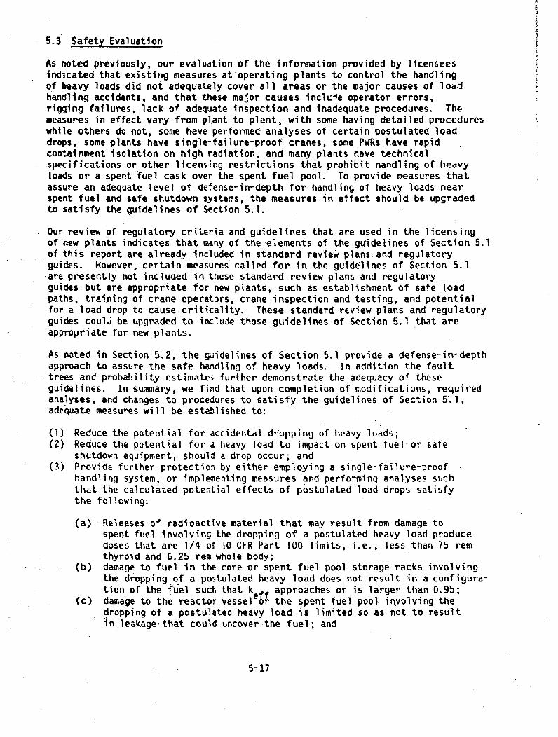
5.3 Safety Evaluation
As noted previously, our evaluation of the information provided by licenseesindicated that existing measures at operating plants to control the handlingof heavy loads did not adequately cover all areas or the major causes of loadhandling accidents, and that these major causes inclke operator errors,rigging failures, lack of adequate inspection and inadequate procedures. Themeasures in effect vary from plant to plant, with some having detailed procedureswhile others do not, some have performed analyses of certain postulated loaddrops, some plants have single-failure-proof cranes, some PWRs have rapidcontainment isolation on high radiation, and many plants have technicalspecifications or other licensing restrictions that prohibit nandling of heavyloads or a spent fuel cask over the spent fuel pool. To provide measures thatassure an adequate level of defense-in-depth for handling of heavy loads nearspent fuel and safe shutdown systems, the measures in effect should be upgradedto satisfy the guidelines of Section 5.1.
Our review of regulatory criteria and guidelines- that are used in the licensingof new plants indicates that many of the elements of the guidelines of Section 5.1of this report are already included in standard review plans and regulatoryguides. However, certain measures called for in the guidelines of Section 5.1
-are presently not included in these standard review plans and regulatoryguides but are appropriate for new plants, such as establishment of safe loadpaths, training of crane operators, crane inspection and testing, and potentialfor a load drop to cause criticality. These standard review plans and regulatoryguides coulJ be upgraded to include those guidelines of Section 5.1 that areappropriate for new plants.
As noted in Section 5.2, the guidelines of Section 5.1 provide a defense-in-depthapproach to assure the safe handling of heavy loads. In addition the faulttrees and probability estimates further demonstrate the adequacy of theseguidelines. In summary, we find that upon completion of modifications, requiredanalyses, and changes to procedures to satisfy the guidelines of Section 5.1,-adequate measures will be established to:
(1) Reduce the potential for accidental dropping of heavy loads;(2) Reduce the potential for a heavy load to impact on spent fuel or safe
shutdown equipment, should a drop occur; and(3) Provide further protection by either employing a single-failure-proof
handling system, or implementing measures and performing analyses suchthat the calculated potential effects of postulated load drops satisfythe following:
(a) Releases of radioactive material that may result from damage tospent fuel involving the dropping of a postulated heavy load producedoses that are 1/4 of 10 CFR Part 100 limits, i.e., less than 75 remthyroid and 6.25 rem whole body;
(b) damage to fuel in the core or spent fuel pool storage racks involvingthe dropping of a postulated heavy load does not result in a configura-tion of the fUel sucIt that ke~f approaches or is larger than 0.95;
(c) damage to the reactor vessel r the spent fuel pool involving thedropping of a postulated heavy load is limited so as not to resultin leakage-that could uncover the fuel; and
5-17

(d) damage to equipment from redundant safe shutdown paths involving thedropping of a postulated heavy load will be limited so as not toresult in loss of required safe shutdown fwctions.
.-For those guidelines that rely on probabilities of events being small,the fault trees discussed in Section 5.2 demonstrate that the probabilityof unacceptable consequences is very low.
Interim Protection
At present there is little handling of spent fuel shipping casks. Once offsitewaste repositories are established, the frequency of cask handling will increasesignificantly. To provide reasonable assurance that mo casks or other heavyloads are handled over the spent fuel pool until final implementation of theguidelines of Section 5.1, technical specifications should be upgraded toprohibit handling of heavy loads over the spent fuel pool. -As noted previously,many plants already have such a specification.
Definition of. safe load paths, development of load handling procedures, trainingof crane operators, and inspection of cranes are procedural or administrativemeasures that can be accomplished in a relatively short time period and neednot be delayed for completion of evaluations and modifications to satisfy theguidelines of Section 5.1. Implementation of these measures will furtherreduce the potential for accidental load drops to impact on fuel in-the coreor spent fuel pool. Additionally a special review of procedures, equipment,and personnel for handling loads over the core provides greater assurance ofthe safe handling of such loads.
We therefore find that to assure safe handling of heayy loads in the interimperiod until measures at operating plants are upgraded to satisfy the guidelinesof Section 5.1, implementation of the following measures should be initiated:
(1) Licenses for all operating reactors not having a single-failure-proofoverhead crane in the fuel storage pool area should be revised to includea specification comparable to-Standard Technical Specification 3.9.7,"Crane Travel - Spent Fuel Storage Pool Building' for PWR's and StandardTechnical Specification 3.9.6.2, "Crane Travel," for BWR's, to prohibithandling of heavy loads over fuel in the storage pool until implementationof measures which satisfy the guidelines of Section 5.1 (see Table 3.2-1).
(2) Safe load paths should be defined per the guidelines of Section 5.1.1(1);•(3) Procedures should be developed and implemented per the guidelines of
Section 5.1.1(2);(4) Crane operators should be trained, qualified and conduct themselves per
the guidelines of Section 5.1.1(3); and(5) Cranes should be inspected, tested, and maintained in accordance with the
guidelines of Section 5.1.1(6).(6). In addition to the above, special attention should be given to orocedures,
equipment, and personnel for the handling of heavy loads over the core,such as vessel internals or vessel inspection tools. This special reviewshould include the following for these loads: (II) review of proceduresfl installation of rigging or lifting devices ard movement of the loadtLn assure that sufficient detail is provided and that instructions areclear and concise; (2) visual inspections of load bearing components of
5-18
cranes, slings, and special lifting devices to identify flaws or deficienciesthat could lead to failure of the component; (3) appropriate repair andrcplacement of defective components; and (4) verify that the crane operatorshave been properly traineo and are familiar with specific proceGures usedin handling these loads, e.g., hand signals, conduct of operations, andcontent of procedures.
Implementation of the above measures will provide reasonable assurance thathandling of heavy loads will be performed in a safe manner, until final imple-mentation of the guidelines of Section 5.1. Additional)y, operating experiencehas shown that no heavy load drop accidents damaging irradiated fuel haveoccurred in over 400 reactor years of operating experience. The above recom-mended interim actions will further reduce the potential for accidental loaddrops to damage irradiated fuel. On the basis of previous operating experienceand the additional interim measures, we find that continued power operationand refueling operations until final implementation of the guidelines ofSection 5.1 does not present undue risk to the health and safety of the public.
5-19

6. RESOLUTION OF THE ISSUE
The following is a summary of those recommended actions that should be takento resolve the concern over the handling of heavy loads near irradiated fuel,or safety related equipment.
6.1 Implementation of Guidelines - Operating Plants
It is recommended that a program be initiated to assure that the guidelines ofSection 5.1 of this report are implemented at operating facilities. Thisprogram should include the following:
(1) Transmittal of a generic letter to licensees requesting details describinghow the guidelines of Section 5.1 will be met, including required modifica-tions Lnd results of analyses;
(2) Availability of NRC staff personnel or outside technical assistance toevaluate information submitted by licensees in response to the abovegeneric letter. Such outside technical assistance would require expertisein various areas, including crane design and operation, structural'andmechanical analyses, accident analysis (radiological doses), criticalitycalculations, and plant refueling operations and administrative controls.The issistance required on specific plants may vary, depending on thealternatives selected; however, expertise in each of the above areas willbe required for the program.
As noted in Section 3 many operating plants already meet certain of theguidelines, such as single-failure-proof cranes at 15 plants, and thusthe impact of satisfying the guidelines will be reduced.
(3) A safety evaluation should be prepared on each facility providing thebasis for the conclusion that load handling will be carried out in a safemanner at that facility.
6.2 Interim Actions
To provide adequate assurance that handling of heavy loads will be performedsafely in the interim period until final implementation of changes required tosatisfy the guidelines of Section 5.1, it is recommended that the interimmeasures described in Section 5.3 be implemented.
6.3 Changes to SRPs and RGs
At n%?w facilities certain of the problems that are present in older operatingfacilities do not exist. For example, many operating plants require placementof the shipping cask in the spent fuel pool for loading with spent fuel. Suchan operation makes fuel in the storage pool and storage pool integrity moresusceptible to damage due to an accidental load drop. However, new facilitiesprovide a separate cask loading pit that is well separated from the spent fuelpool, and spent fuel assemblies are individually transported through a canalfrom the spent fuel pool for loading 'in the cask. Because many of the potentialload handling problems that exist at present operating facilities are not
6-1
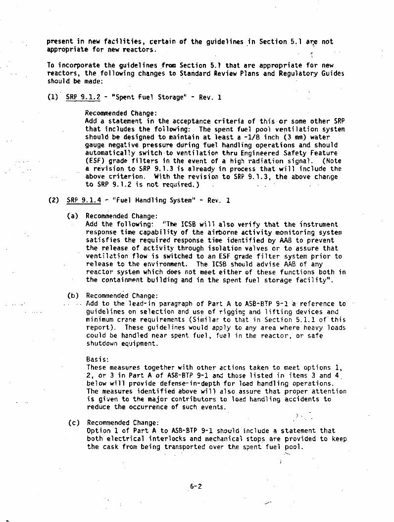
present in new facilities, certain of the guidelines in Section 5.1 are notappropriate for new reactors.
To incorporate the guidelines from Section 5.1 that are appropriate for newreactors, the following changes to Standard Review Plans and Regulatory Guidesshould be made:
(1) SRP 9.1.2 - "Spent Fuel Storage" - Rev. 1
Recommended Change:Add a statement in the acceptance criteria of this or some other SRPthat includes the following: The spent fuel pool ventilation systemshould be designed to maintain at least a -1/8 inch (3 mm) watergauge negative pressure during fuel handling operations and shouldautomatically switch-to ventilation thru Engineered Safety Feature(ESF) grade filters in the event of a high radiation signal. (Notea revision to SRP 9.1.3 is already in process that will include theabove criterion. With the revision to SRP 9.1.3, the above changeto SRP 9.1.2 is not required.)
(2) SRP 9.1.4 - "Fuel Handling System" - Rev. 1
(a) Recommended Change:Add the following: "The ICSB will also verify that the instrumentresponse time capability of the airborne activity monitoring systemsatisfies the required response tine identified by AAB to preventthe release of activity through isolation valves or to assure thatventilation flow is switched to an ESF grade filter system prior torelease to the environment. The ICSB should advise AAB of anyreactor system which does not meet either of these functions both inthe containment building and in the spent fuel storage facility".
(b) Recommended Change:Add to the lead-in paragraph of Part A to ASB-BTP 9-1 a-reference toguidelines on selection and use of rigging and lifting devices andminimum crane requirements (Similar to that in Section 5.1.1 ofthisreport). These guidelines would apply to any area where heavy loadscould be handled near spent fuel, fuel in the reactor, or safeshutdown equipment.
Basis:These measures together with other actions taken to meet options 1,2, or 3 in Part A of ASB-BTP 9-1 and those listed in items 3 and 4below will provide defense-in-depth for load handling operations.The measures identified above will also assure that proper attentionis given to the major contributors to load handling accidents toreduce the occurrence of such events.
(c) Recommended Change:Option 1 of Part A to ASB-BTP 9-1 should include a statement thatboth electrical interlocks and mechanical stops are provided to keepthe cask from being transported over the spent fuel pool.
6-2

Basis:This option presently relies op electrical interlocks and mechanicalstops to i(eep the cask away from the spent fuel pool, however theSRP does not include this detail. The above change only documentsthe criteria that are presently being used.
(d) Recommended Change:Add to the statement on the evaluation criteria of option 3 ofPart A to ASB BTP9-I that the consequences of a postulated load dropshould also not result in criticality or excessive leakage thatcould uncover the fuel.
Basis.These are potential consequences that should be considered in theanalyses.
(e) Recommended Change:Guidelines should be added on rigging, special lifting devices, andinterfacing lift points to be used with a single-failure-proofcrane. These guidelinesshould be similar to Section 5.1.6 of thisreport.
Basis:Guidelines in ANSI standards on slings and special lifting devicesare available and should be used to assure the reliability of thesecomponents. Additionally, guidance should be provided on interfacinglift points since failure of these could potentially result in aload drop.
(3) SRP 13.1.3 "Qualifications of Nuclear Plant Personnel"
Recommended Change:Add to the acceptance criteria a statevent that crane operators that mayhandle heavy loads over or near fuel in the reactor, fuel in the storagepool, or safe Shutdown equipment are qualified and conduct themseves inaccordance with the guidelines of ANSI B30.2-1976 (Chapter 2-3) "Overheadand Gantry Cranes."
(4) R.G. 1.33 - "Quality Assurance Prgram Requirements (Operation)," Rev. 2
(a) Recommended Change: Add to section 2 of Appendix A to this guidethat general plant operating procedures should also be developed forthe following: (1) handling of heavy loads near fuel in the reactor,fuel in the storage pool, or safe shutdown equipment; and (2) identi-fication of safe load paths;
(b) Recommended Change: Add to Section I of Appendix A to this guidethat administrative procedures should also be developed for qualifica7>tion, training, and conduct-of crane operators.
6-3

(5) Regulatory Guide 1.13, Revision 1 - "Spent Fuel. Storage Facility DesignBasis'
Recouomended Change:Regulatory Guide 1.13, Regulatory Position C.5 should be changed todelete the three options listed and to list option 1 of ASB 9-1, withrecomended changes (see changes to SRP 9.1.4).
Basis:ASB 9-1 offers only the option of keeping the cask away from the spentfuel pool using e~ectrical interlocks and mechanical. stops. This makesthe regulatory guidance consistent with the remiew criteria.
(6) Regulatory Guide 1.XX -
Recommended Change:A regulatory guide should be developed endorsing ANSI N14.6, 1978 "StandardFor Snpcial Lifting Devices for Shipping Containers Weighing 10,000
-Pounds (4500 kg) or More For Nuclear Materials'. ANSI N14.6 providesguidelines that are not peculiar to lifting deiices for shipping containers;-these guidelines would be applicable to any special lifting-device.Therefore, the sgulatory guide that is develmed to endorse ANSI N14.6should endorse this standard for use in designing and using speciallifting devices that handle heavy loads over or near spent fuel, fuel inthe core, or safe shutdown equipment.
Basis:Such a regulatory guide will facilitate use of industry guidelines inevaluating the adequacy to special lifting devices in the licensingreview process, and will provide guidance to applicants, licensees, andvendors in designing special lifting devices.
6.4 Technical Specification Changes
Following implementation of modifications and changes to satisfy the guidelinesof Section 5.1, changes to facility technical specifications should be made.Items which should be covered by technical specifications will vary dependingon the alternatives selected by the particular plant. The following summarizesthe types of specifications T'equired for each of the guidelines of Section 5.1.
Guideline Related Technical Specification (see code below)
5.1.1(1)-(6) (No T.S. Change required)5.1.1(7) A5.1.2(l) (Same as 5.1.6)5.1.2(2) A, B, C, E5.1.2(3) A, B, C, E5.1.2(4.) A - E (as appropriate, based on analysis)5.1.3(l) (Same as 5.1.6)
E L3(2) A, E, F5.1.73(3) A, E5.1.4(l) (Same as 5.1.6)5.1.4(2) A, C, (and B or Q ifapprcpriate)5.1.5(0)(a) (Same as 5.1,6)
6-4
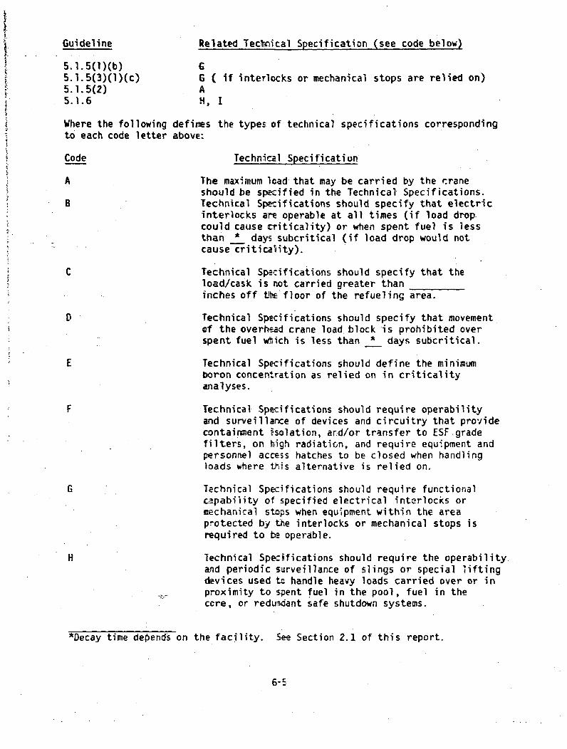
Guideline Related Tectrical Specification (see code below)
5.l.5(l)(b) G5.1.5(3)(1)(c) G ( if interlocks or mechanical stops are relied on)5.1.5(2) A5.1.6 H, I
Where the following defines the types of technical specifications correspondingto each code letter above:
Code Technical Specification
A The maximum load that may be carried by the craneshould be specified in the Technical Specifications.
B Technical Specifications should specify that electricinterlocks are operable at all times (if load drop-could cause criticality) or when spent fuel is lessthan * days subcritical (if load drop would notcause criticality).
C Technical Specifications should specify that theload/cask is not carried greater thaninches off the floor of the refueling area.
D Technical Specifications should specify that movementof the overhead crane load block is prohibited overspent fuel w•ich is less than * days subcritical.
E Technical Specifications should define the minimumboron concentration as relied on in criticalityanalyses.
F Technical Specifications should require operabilityand surveillarce of devices and circuitry that providecontainment ,solation, ard/or transfer to ESF.gradefilters, on high radiatirn, and require equipment andpersonnel access hatches to be closed when handlingloads where this alternative is relied on.
G Technical Specifications should require functionalc.-pabiiity of specified electrical interlocks oraechanical stops when equipment within the areaprotected by the interlocks or mechanical stops isrequired to be operable.
H Technical Spe:ifications should require the operability.and periodic surveillance of slings or special liftingdevices used to handle heavy loads carried over or inproximity to spent fuel in the pool, fuel in theccre, or redundant safe shutdown systems.
*Decay time depends on the facility. See Section 2.1 of this report.
6-5

Code Technical Specification
I Technical Specifications should require operabilityof both load paths in the single-failure-proof crane,where dual load paths are provided.
6.5 Issues Requiring Further Staff Review
In the course of completing Task A-36, certain areas of potentially adversesafety consequences were identified that wre beycnd the original scope ofTask A-36, such as the potential for heavy loads to damage fuel in the coreand the potential for heavy loads, if dropped, to damage safe shutdown systems.To resolve these areas of concern, the scope of Task A-36 was expanded toinclude these concerns because the loads handled, the equipment used to handlethe loads, and the guidelines for safe handling wculd be-the same as thatwhich was already under review in Task A-36.
/
Task A-36 did not consider loads that weighed less than a "heavy" load, wherea "heavy" load is defined as any load greater than- the weight of a spent fuelassembly and its handling tool. The handling, anc accidental dropping,of aspent fuel assembly is already reviewed as a fuel handling accident, andtherefore was not within the scope of Task A-36. In the hearing before theAtomic Safety and Licensing Board in the iatter of increased spent fuel storagecapacity for Trojan Nuclear Plant, the board raised concerns over the' potentialfor loads which weighed less than a fuel assembly to be carried at greaterheights and thus be able to cause more dazage mhar a dropped fuel assembly.The board accepted a technical specification which required that loads shouldnot 5e handled over the sp-ent fuel pool at heights such that the kineticenergy of the load, if dropped, would be greater than the kinetic energy of afuel assembly if dropped from its maximum carryinc height.
It was determined that an evaluation of tUe handlirg of lighter loads, thepotential for dropping, measures to preclude dropping, potential consequences,and required staff guidelines were beyond the scope of Task A-36. Additionallythe generic letter sent to licensees in Juie of 1S78 did not requ.:t anyinformation on lighter loads, such as type- and size of loads, frequency ofmovement, or measures in effect to preclude dropping.
It is therefore recommended that a separate task te established to review thehandling of loads weighing less than a sp-ent fuel assembly and to establishnecessary guidelines for their safe handling. This task should identify typesof small loads handled and frequency of movement cver spent fuel, pctentialFor a load drop to occur, potential consequences cf a small load drop, a-idrequired guidelines that are consistent with the ýhilosophy used for thecontrol of heavy loads. To the extent practical, guidelines for the controlof small loads should be similar to those used fo- heavy loads.
In the interim period until completion of this neo task, it is recommendedthat a technical specification change be nade to the licenses uf all operatingfacilities to include a limit on kinetic energy oý loads carried over thespent fuel pool similar to technical spec'ficatior 3.9.7 for Trojan (SeeAppendix D). We do not have information zvaiiabl= or precedents to rely oifor establishing interim aeasures for the control of small loads handled overthe reactor core. The above recommended task wou-d have to establish; suchrequired measures.

APPENDIX A
ANALYSES OF POSTULATED LOAD DROPS
Certain of the alternatives in Sections 5.1.2 through 5.1.5 of this reportcall for an analysis of postulated load drops and ev.luation of potentialconsequences to assure that the evaluation criteria of Section 5.1 are met fcrsuch an event. Section A-1 of this appendix identifies certain considerationsthat should be included in such evaluatiuns. Sections A-2 and A-3 identifycertain additional considerations and assumptions that should be used inanalyzing the potential ccnsequences of a drop of the reactor vessel headassembly or the spent fuel shipping cask; other load drops that are analyzedshould use similar considerations and assumptions that are appropriate forthese other loads. Section A-4 provides guidance in performing criticalitycalculations.
1. GENERAL CONSIDERATIONS
Analyses of postulated load drops should as a minimum include the considera-tions listed below. Other considerations may be appropriate for the particularload drop being analyzed; for example, for a reactor vessel head assembly or aspent fuel cask drop analysis, the additional considerations listed inSections A-2 or A-3 should be used. In eialuating the potential for a loaddrop to result in criticality, the considerations of A-4 should also befollowed. The following snould be consi.ered for any load drop analysis. asappropriate:
(1) That the load is dropped in an orient..ation that causes the most severeconsequences;
(2) That fuel impacted is 100 hours subcritical (or whatever the minimum thatis allowed in facility technical spe:ifications prior to fuel handling);
(3) That the load may be dropped at any location in the crane travel areawhere -icvement is not restricted by nechanical stops or electricalinterlocks;
(4) That credit may not be taken for sppnt fuel pool area charcoal filters ;fhitches, wall, or roof sections are removed during the handling of th-heavy load being analyzed, or whenever the building negative pressurerises above (--)1/8 inch (-3 m) water gauge;
(5) Analyses that rely on results of Table 2.1-1ior Figures 2.1-1 or 2.1-2for potential offsits doses 6r safe decay times should verify that theassumptions of Table 2.1-2 are conservative for the facility under review.X/Q values should be derived fron analysis of on-site metenrologicalmeasurements based on 5T worst meteorological conditions.
(6) Analyses shoulo be basid on an elastic-plastic curve that represents atrue stress-strain relationship.
A-1

(7) The analysis should postulate the "maximum damage" that could result,i.e., the analysis should consider that all energy is absorbed by thestructure and/or equipment that is impacted
(8) Loads need not be analyzed if their load paths and consequences arescoped by the analysis of some other load.
(9) To overcome water leakage due to damage from a load drop, cred!it may betaken for borated water makeup of adequate concentration that is requiredto be availablE by the technical specifications.
(10) Credit may not be taken for equipment to operate that may mitigate theeffects of the load drop if the equipment is not required to be operableby the technicel specifications when the load.could be dropped.
2. REACTOR VESSEL HEAD DROP ANALYSIS*
Where a reactor vessel head drop analysis is to be performed to satisfy thePWR Containment or BWR Reactor Building guidelines (Sections 5.1.3 or 5.1.4)of this report, the analysis should consider the following to assure that theevaluation criteria of Sectic-i 5.1 are satisfied.
(1) Impact loads should include the weight of the reactor vessel (RV) headassemblly (including all appurtances), the crane load block, and otherlifting apparatus (i.e., the strongback for a BWR).
(2) All potential accident cases during the refueling operation-. Areas ofconsideration as a minimum should be:
(a) Fall of the RV head from it's maximum height while still on theguide studs followed by impact with the RV flange;
(b) Fall of the RV head from its maximum height considering possibleobjects of impact such as the guide studs, the RV flange, the steamdryer (BWR) or structures beneath the path of travel; and
(c) Impact with the fueling cavity wall due to load swing with thesubsequent drop of the RV head due to lifting device or wire ropefailure.
(3) All cases which are to be considered should be analyzed in the actualmedium present during the postulated accident, e.g., for a PWR prior toreassembly of the reactor, the fueling cavity is drained after the headengages the guide studs to allow for visual inspection of the reactorcore control drive rods insertion into the head. During this phase itshould be considered that the head will only fall through air, withoutany drag forces~produced by a water environment.
*These guidelines only consider the dropping nf the RV head assembly doringrefueling and do not apply directly to dropping of the reacter internals suchas the steam dryer (BWR), moisture- separator (BWR) or the upper core internals(PWR); however, similar assumptions and considerations would apply to analysesof dropping of reactor internals.
A-2
(4). In those Nuclear Steam Supply Systems where portions of the reactorinternals extend above the RV flange, the internals should be analyzedfor buckling and resultant adverse effects due to the impact loading ofthe RV head. It should be demonstrated that the energy absorptioncharacteristics (causing buckling failure) of these internals should bz?such that resultant damjage to the core assembly does not cause a conditionbeyond the acceptance criteria for this analysis.
(5) Reactor vessel supports should be evaluated for the effects of thetransmitted impact loads of the RV head. In the case of PWRs where theRV is supported at its nozzles, the effects of bending; shear andcircumferential stresses on the nozzles should be examined. For BWRs theeffects of thcse impact loads on the RV support skirt should be examined.
(6) The RV head assembly should be considered rigid and not experiencedeformation during inpact with other componEr .s ar structures.
3. SPENT FUEL CAK DROP ANALYSIS
Where a cask drop analysis is to be performed to satisfy the guidelines inSections 5.1.2, 5.1.4, or 5.1.5 of this report, it should consider the followingin addition to the general considerations of Section A-l to assure that theevaluatio.a criteria of Section 5.1 are satisfied:
(1) Applying a single-failure to the lifting assembly, consider that the caskis dropped in an orientation that will result in the most severe consequences.
(2) Impact loads should include a fully loaded cask (with water, where applicable)and all equipment required for lifting and set down such as baseplates,lifting yokes, wire ropes and crane blocks.
(3) Restricted patt travel of the spent fuel cask (defiied by electricalinterlocks, mechanical stops, and crtne travel capability) should beevaluated to determine the locations and probable accident cases alongthe path where damage could occur to:
(a) the floor and walls of the Spent Fuel Pool (SFP);(b) racks within the SFP which suppcrt the spent fuel;(c) the spent fuel itself;(d) the refueling channel gate; or(e) safety related systems, components and structures beneath or adjacent
to the travel path of the cask.
(4) In the analysis consideration may be given to drag forces caused by theenvironment of the postulated accident case, e.g., when the spent fuelcask is postulated to drop into the SFP, credit may be takfn -for dragforces caused by the water in the SFP. Water level assumec- for suchanalyses should be the minimum level allowed by technical specifications.
(5) Credit may be tak-n for energy absorbing devices integral to the cask ifattached during the handling operations in determining thE amount ofenergy imparted to the spent fuel or safety related systems, componentsor structures.
A-3

I.
(6) For the purpose of the analysis the cask should be considered rigid(except for devices and appurtences specificilly designed for energyabsorption and in place) and not to experience deformation during impact.
(7) In the calculating the center of gravity, consideration should be givento modifications made to the cask after purchase, e.g., addition of aperforated metal basket within the cask.
4. CRITICALITY CONSIDERATIONS
4.1 Spent Fuel Pool Neutronics Analysis
In Sections 5.1.2, "Spent Fuel Pool Area - PWR," and 5.1.4, "Reactor Building -BWR," a number of alternatives are presented for the contro; of heavy loads inspent fuel pool ar!-,s. Some of these alternatives ;,iclude neutronics calcula-tions to demonstrate tit crushing the fuel and fuel rack will not result incriticality. This section is included here to give the licensees guidance inperforming their neutronics calculation.
A discussion of the potential for criticality under load drop conditions isdiscussed in Section 2.2, and summarized in Section 2.2.6. The results ofthis section should be used as a guide to determine which neutronics or otheranalyses are required to evaluate the potential for criticality for a specificplant area. A licensee may choose to use the results of section 2.2, ratherthan performing an independent neutror'ics analysis for his plant. If a licenseeuses the re:ults of Section 2.2 rather than performing an independent neut-onicsanalysis, he should verify that the assumptions and model fuel assembly ofSection 2.2 are valid for his plant.
For PWR spent fuel pools, credit may be taken under the accident conditions ofa Icid drop for the boron in the spent fuel pool water to maintain subcriticality.In this case the required boron concentration should be specified in thefacility Technical Specification, and regular monitoring of the boronconcentration in the spent fuel pool should also be specified. Likewise, ifthe neutronics analysis postulates a bounding distribution of non-spent fuelwithin the spent fuel pool, then the Technical Specifications must be modifiedto require that the actual distribution of fuel is no more deleterious thanthat assumed in the analysis-. In postulating a limiting distribution ofnon-spent fuel, the licensee may either assume an infinite array or a finitearray. The largest finite array of non-spent fuel a licensee should have toconsider would be that of an off-load core.
In thi's neutronics analysis the licensee must demonstrate that the fuel remainssubcritical in the optimum crushed configuration. It is adequate to assumethat the optimum configuration is with the rack crushed to uniformly reducethe separation between assemblies and the spacing between fuei pins uniformlyreduced to maximize k All' Tboral and structural material may be assumed toremain in its originalftonfiguration relative to the fuel, and not forced outof the fuel array.
The neutronics analysis for the spent fuel pool should consider the case whereit has become necessary to 'ff-load an entire cort into the spent fuel pooland a heavy load is dropped on fuel in the pool.
A-4

As noted in Section 5.1.4 it is not necessary to analyze the effects nf crushingon-k for BWR spent fuel pools that use boron nlate cans and do not rely onspacA to maintain subcriticality.
4.2 Reactor Core Neutronics Analyses
4.2.1 Neutronics Analyses for a BWR Core
For a BWR core, the potential for a. load drop to drive control rods out of thecore should be analyzed using the appropriate considerations of Sections A-land A-2. If this analysis shows that postulated load drops could drive controlrods out of the core, the number of rods that could be affected should bedetermined, and a neutronics analysis performed to determine the potential forcriticality to result. If in the analysis it is assumed that all rods are inthe core just prior to the load drop, then the facitity technical specificationsshould require that all rods are in when handling a heavy load over the core.
4.2.2 Neutronics Analyses for a PWR Core
In Taole 2.2-2, we see that crushing the model PWR core in 2000 ppm bororrefueling water increases k by about 0.02. Since only one model fuelgeometry was considered herffother fuel geometries could have a slightlyhigher reactivity inserti'on due to crushing. A value of 0.05 may be used as abounding worst case reactivity insertion value due to crushing of a PWR core.In performing a neutronics evaluation of a postulated load d.'op on a PWR core,a licensee may use this estimated reactivity insertion limit in lieu of performinga plant specific calculation. If a licensee can demonstrate that for his fuela value less than 0.05 is bounding, then he may use this lower value instead.
The current Technical Specifications require that during refueling k ef shouldbe maintained at 0.95 or less. This is based on an uncrushed core.e¶ performa neutronics analysis to demonstrate that crushing the core will not drive itcritical at *east two alternatives for demonstrating this are acceptable.
(1) The licensee can perform a neutronics analysis on his core uniformlycrushed in the x-y direction to maximize k If the licensee choosesthis option he must demonstrate that the msxTmum keff is no greater than0.95, with all uncertainties taken into account.
OR(2) Using his core refueling neutronics analysis (uncrushed), the licensee
can demonstrate that k for the uncrushed core is no greater than 0.90.Then, using the estimatA 0.05 maximum reactivity insertion due to crushing,the maximum achievable keff is still less than 0.95.
5. ACCEPTANCE CRITERIA
In perform.ing the above analyses, the acceptance criteria for resultant damageshould be that it does not cause a condition that may exceed evaluationcriteria I-IV stated in Section 5.1 of this report.
A-5

APPENDIX B
ESTIMATES OF EVENT PROBABILITIES
Fault trees (Figures 5.2-1, 5.2-2, and 5.2-3) for various load handling scenarios
are contained in Section 5.2 of this report. This appendix develops probability
estimates for the various events contained in these fault trees.
The numbers in "he left hand margin correspond with the event numbers shown in
Figures 5.2-1, 5.2-2, and 5.2-3. Figures B-1 through B-3 correspond to the
fault trees in Ssction 5.2, but show the probabilities aeuveloped in this appendix.
Probabilities used are best estimatec of upper and lower bounds with conservative
margins to allow for uncertainties. Where little data is available, estimates
are based on engineering judgment as to a conservative value. For the purposes
of determining a median within the ra"-e between the upper and lower bounds, it
was assumed that the variabi;ity of failure rates was distributed log normally
between the bounds.
A. Figure 5.2-1 - Loads Handled Near Spent Fuel Pool:
Offsite Releases
1.1.1 The probability that the spent fuel pool contains "hot" spent fuel dependson the de.ay time of the spent fuel. From Figures 2.1-1 and 2.1-2, between
42 and 74 days is a safe decay time if a full core were damaged. If we
e.sume that heavy loads are handled uniformly through the year and that
any heavy load could cause excessive releases, then the P(l.l.l) is between
0.1 and 0.2 per reactor year (i.e., 38/365 to 72/365).
1.1.2.1 For the purposes of this review, it is estimated that the probability offailure to follow a given procedure is between 5 x i0-2 and 1-2 per
event, or 2 to 10 failures per year assuming 200 lifts per year. This
presumes that the guidelines of Section 5.1.1 are met, whereby craneoperators are trained in proper conduct of operation and procedures tc be
followed. The 200 lifts per year is based on the number of cask and other
load handling events that may occur per year as shown in Table 3.1-1. The
B-i

aboveestimate of failure to follow a given procedure is also consistent
- with human reliability estimated failure rate of 10-2 obtained in the
Reactor Safety Study WASH-1400 based on data from the United Kingdom
Atomic Energy Agency and the U.S. military.
1.1.2.2- Electrical interlock reliability was estimated to be between 102 and 10"3
per demand. These interlocks are not challenged unless there is a failure
to follow prescribed load paths (i.e., event 1.1.2.1). This estimate is
more conservative than the electrical interlock failure rate assessment
used in WASH-1400 of 10 to 10 per demand. The higher failure rate was
used to account for the potential that there may be some interaction with
the event of failure to foi.ow the prescribed load path, whereby an
inexperienced operator violates the load path procedure and also fails to
verify that interlocks are operable or intentionally bypasses the interlock.
..1.2.3 Based-on the data collected from the Navy, it is expected taat the probability
of handling system failure for nuclear plant cranes will be on the order
of between 10"5 and 1.5 x 10⁻⁴ per lift. This presumes an improvement by
a factor of 0.5 over the Navy cranes based on improved procedures at
nuclear plants, and conformance to guidelines in Section 5.1.1 of this
report concerning operator training and crane inspection (i.e., the failure
rate will be cut in half due to these measures).
However, the probability of handling system failure, given that the prescribed
load path has not been followed and tViat electrical interlocks have failed,
would be greater than the above estimate. This would be due to common
mode effects such as a poorly trained or unqualified operator that fails
to follow the prescribed load path, fails to check the operability of the
interlocks, and then proceeds to improperly operate the handling system
leading to a ]cad drop. This then is a connecti-,e link between events
1.1.2.1, 1.1.2.2, and 1.1.2.3. If we presume that this reduces the handling
system reliability by a factor of ten, this gives a result of prrbability
of handling system fcilure given that ;iterlocks have failed and 'he-4operator has failed to follow the prescribed load path of betweey 10 and
1.5 x 10"3 per lift.
B-2
1.2..4 Even though interlocks fail and procedures are violated, the load may not
be-brought over spent fuel or the load may be dropped at some point prior
to or after being brought over spent fuel. Even if the drop occurs over
spent fuel it may not impact "hot" spent fuel. Based on the length of the
load paths that could be followed for such loads as contaminated waste
casks, transfer canal gate, spent fuel cask, shield olugs and uther loads
normally handled near spent fuel, spent fuel usually occupies less than
10% of any potential path length and many possible paths do not even go
over spent fuel. Based on this, it is estimated that the probability that
te. thedrp could occur over "hot" spent fue&, given th't the prescibed loadI--path has not been followed, is between 10i and 102, given that events
1.1.2.1, 1.1.2.2, and 1.1.2.3 occur.
1.1.2 Combining probabilities, it is estimated that P(1.1.2) is between 2 x 10"*5
and 2 x 10⁻⁹ with a median of approximately 10-7 per reactor year.
1.1 Combining 1.1.1 and 1.1.2, we obtain an estimate of the probability of
offsite releases that exceed guidelines due to a load drop for loads
handled near spent fuel of between 4 x 10 and 2 x 10¹⁰ with a median of
2 x 1-8 per reactor year.
1.2.1 Potential For Criticality
This event can occur if a core OfT load were to occur, whereby the fuel in
the core has been subcritical for a short period of time such that it
still contains some enriched fuel. It is estimated that a core off-load
event may occur once every 50 to 200 reactor years, giving a probability-2 -3
of core off-load of tzeteen 2 x 10 and 5 x 10 per reactor year.
1.2.2 This requires failure of an operator to follow prescribed refueling
procedure•. As in other similar operator actions, the probability of
failure is estimated to be between 5 x 10⁻² and 10- 2 per event, if
independent from other 1.2 events. However, given that the prescribed
load path has not been followed, that the electrical interlocks have
failed, and that the handling system has failed (i.e., given that 1.2.3
occurs), the probability that boron concentration is inadequate could be
B-3

greater than the above estimate. This would be due to common mode
effects, s.ch as a poorly trained or unqualified crane operator which
increases the probability of each of these events occurriig simultane-
ously. If we pressume that such an effect increases by a factor of 10 the
pronability of having inadequate boron concentration, this gives a
probability of 5 x 10⁻¹ to 10"1 per event.
1.2.3 This is similar to event 1.1.2, except that the area of concern is highly
enriched fuel that could be brought critical rather than "hot" spent fuel
in terms of potential for an excessive release. The probability that the
load strikes, this fuel, given that highly enriched fuel is i-i the pool is
the same as the probahility of event 1.1.2.
1.2.4 This is also largely unknown; however, if we consider all the possible
configurations that spent fuel could be in after impact by a heavy load,
only very few of these are such that the spent fuel is brcught uniformly
close together with the potential for -riticality. It is estimated that
this probability is between 101 and 1-3.
1.2 Combining probabilities we find that the probability of criticality in
spent fuel to result from a load drop for loads handled near spent fuel is
negligible.
1. Combining 1.1 and 1.2 gives, for loads handled near spent fuel: an
estimate that consequences exceed .iuidelines of between 2 x 10 10 and
4 x 10⁻⁶ with a median of approximately 2 x 10"8 per reactcryear.
B. Figure 5.2-2 - Loads Htndled Over Spent Fuel Pool:
Offsite Releases
2.1.1.1 This is the same as the probability of event 1.1.2.3.
2.1.2 This is the same as the probability of event 1.1.1.
2.1.1.2.1.1 This is the same as the probability of event 1.1.2.1.
B-4

2.1.1.2.1.2
2.1.1.2.2.1
2.1.1.2.2.2
2.1
TLie requirement to segregate "hot" spent fuel would ba specified in
facility refueling procedures, as well as facility te-hnical specifi-
cations. Failure to segregate "hot" spent futi would be a failure to
follow prescribed procedure. For other operator actions, the
probability of failure to follow a procedure is estimated to be
between 5 x 10⁻² and 10-2 per event. However, in this case,
refueling operations call for a check on fuel position in the pool
following refueling. This will tend to reduce the probability of
failing to segregate the "hot" spernt fuel away fron the cask area.
It is estimated that this probability is between 102 and 10- per
event.
This is the same as the probability of event 1.1.2.1.
This is the same as thee probability of e,.nt. 1.1.2.2.
Combining probabilities, we obtain an estimate of the probability of
offsite releases that exceed guidelines due to a load drop for loads
handled over the spent fuel pool of between 3 x l0-5 and 2 x 10⁻⁸
2.2.1
2.2.2
2.2.3
2.2.4
2.2.5
with a median of approximately
Potential For Criticality
This is the same as the probability
This is the same as the probability
protected is enriched rather than a
activity.
7 x 10-77 x 10per reactor year.
of event 1.2.1.
of event 2.1.1.2, except the fuel
concern for the release of gap
This is the same as the probability of event 1.1.2.3.
This is the same as the probability of event 1.2.4.
This is the same as the probability of event 1.2.2.
B-5

2.2' .. Coubining probabilitieg we obtain an estimate cf the probability of
criticality in the spent fuel pool due to a load drop for loads handled
over the spent fuel pool of less than 3 x 10⁻⁶ per rexctor year.
2. -Combining 2.1 and 2.2 gives, for loads hbndled over the spent fuel pool, a
prcbabii .y estimate that consequences exceed guidelines of between
2 x 10⁻³ and 3 x 10⁻⁵, with a median of approximately 7 x 10- per
reactor year.
C. Figure 5.2-? - Single Failure Proof Handling Systee:
Offsite Rei• ..s
3. 1.,(A) Lods covered by branch (A) of this fault tree. are large enough to cause
excessive releases if dropped from a sufficient height. The fuel impacted
would in most cases be fuel in the core, and, therefore, would be "hot"
fuel unless the drop occurs before initial criticality. Hiowever, the drop
may occur at low heights where little c.- no fuel damage occurs. , In fact,
most drops due to mechanical failures occur at low lift heights wher: weak
components fail shortly after a load is applied. Additionally, the load
may be deflected by impact with the ,,essel flange or internal suirfaces,
reducing the energy that may be imparted on spent fuel. To account for
this potential for loads carried over spent fuel, it is estimated that
between 10% and 25% of ioad drops directly over "hot" spent fuel result in
releases that ap~roach10 CFR Part 100 limits for loads such as the
reactor vessel head, vessel internals, inspection platform, etc.
Therefore, an estimate of 10-1 and 2.5 x 10- per load drop was used for
the probability that a load dropped on spent fuel results in excessive
offsite releases.
3.1.1(B) This is the same as the probability of event 1.1.1.
3.1.3 Event 3.1.3(B) )is the same as the probability of event 1.1.244. Event
3.1.3(A) covers loads carried over spent fuel. For these loads, between
5 and 25% of the path length is over spent fuel, and, therefore, an
estimate of the probability that the load drop occurs over spent fuel is
B-6
Al
J,

3. 1. 2. l(CF)
between 5 x 10⁻² 3nd 2.5 x.10 1 per each event where the prescribed load
path is not followed.
Section 4 of this report estimates the probability of handling system
failure of between 10-5 and 1.5 x 10⁻⁴ per reactor year for a crane that
does not have sinc'e failure proof features. With the "single-failure-
proof" crane guidelines (NUREG-0554), certain load-bearing components are
provided with dual or counterpart components such that if one were to
fail, its couiterpart could hanale the load and preclude dropping. Events
CF.2.1 and CF.2.2 (shet 2 of Figure 5.2-3) pertair. to these compone'.s
and their counterparts. Certain other cnmponents are allowed to h .%
increased design safety factors per the guidelines of NUREG-0554, in lieu
of having backup or counterpart components. Event CF.4 pertains to thesecomponents which do not have redundant counterparts.
Additionally, the guidelines of NUREG-0554 call for protection against
p3ssible "two-blocking" anu ";oad-hangup" events. This may be done by
limit switches and overload pr,,tection devices respectively, as shown by
the fault trees for events CF.l and CF.3. NUREG-0.34 allcws use of the
limit switches to terminate hoisting as an alternate to designing the
crane to withstand a "two-blocking" event. If designed to withstand
"two-blocking", a test w-uld be performed to demonstrate this ability. It
was deemed that the use of limit switches was the iess reliable of the two
options, and therefore the fault trees modeled use of limit switches.
The fault tree on sheet 2 of Figure 5.2-3 may be -issd both for branches
(A) and (B), (i.e., for events 3.1.2.1(A) and 3.1.2.1(B) with appropriate
probabilities used for the loads covered by each branch).
?
For branch (A) which covers loads carried over spenrt
Table 3.1-1, we see that there are typically betwee.•
year over spert fuel, mostly over thi reactor vessel
internals, vessel inspection equipment, etc). Thus,
branch (A) are estimated on -.he basis. of loads bein
frequency of 4 to 10 times per year•. However, loads
fuel, from
4 and 10 lifts per
(vessel head, vessel
probabilities for
handled at a
covered by branch (B)
B-7

are handled on the order of up to 200 times per year near spent fuel
.(spent fuel shipping cask, was.e/debris/ spent resin casks, refueling
plugs and gates, shield plugs). Similarly, branch (B) probabilities are
estimated usirg these larger frequencies.
In estimating the probability of handling system failure for event
1.1.2.3, it was estimated that there could be some common cause connection
with procedural events, and therefore the estimate of the failure
probability of the hanaling systes was increased. A similar connectionmay exist .or events 3.1.2(B) and 3.1.4(B). However, for event 3.1.2(A)failure of handling system, (if single-failure-proof), no such common
causes could be identified. The probability estimates used in arriving at
the failure probability of the handling system are sufficiently conser-
vative to encompass minor interactions between events 3.1.2(A) and3.1I.1(A) or 3 1.3(A.
CF.l.l Of the 43 events reported in the Navy data report (Section 4 of this
report), 2 "load-hangup" events occurred due to operator error. This
.give.- us an estl.:ate of probability of "m'had-hangup" of between ( x3) x
(0- 5) and (d x(1.5 x 10⁻⁴) or between 4.7 x lO-7 and 7 x l0-6 per lift.
For CF.1.i(A), this gives a result of between 2 x 10⁻⁶ and 7 x 10⁻⁵ per
reactor year (4 to 10 lifts per year). -
For CF.I.I(B), this gives a result of between 10- and 1.4 x 10- per
reactor year (200 lifts per year); however, due to potential common cause
effects with event 3.1.3(B) (failure to follow prescribed load path due to
a poorly trained operator, for exanple) a more -asonable e.timate would
be between 10 and 1.4 x 10 per reactor year.
CF...2 Limit switches are similar to the interlock switches discussed for
event 1.1.2.2, and thus the same probability estimates for event 1.1.2.2
may be used for the limit switches. The complexity of the overload
protection devices is similar to these limit switches, and thus the
probability estimate for limit switches and interlock switches was also
applied to the overload protection devices. The same probability estimate
may be used for CF.l.2(A) and for CF.l.2(B).
B-8

CF.3. 1 "Two-blocking" due to operator error occurred in 15 of the 43 events
reported in the Navy data. This giids ar, estimate for CF.3.1 of between5 5 -4 -6
(•) x (10-5) and (L) x (1.5 x 10-), or between 3.5 x 10 and
5.2 x 10- per lift. For CF.3.1(A), this gives a probability e•timate of- 5--A
between 1.4 x 10 and 5.2 x 10 "' per reactor year (4 - 10 lifts per
year). For CF.3.1(B), this gives an estimate of between 7 x 10⁻⁴ and 10-2
per reactor year (200 lifts per year); however, due to potential common
cause effectý; with event 3.1.4(B) (failure to follow prescribed load path
due to a ýoorly trained opcra-or, for example) a more reasonable estiaate
would be betwee- 7 x 10⁻³ and P1-
CF.3.2 Failire of the limit switch is the same as the probability of :vent CF.1.2
(see di.-ussion of CF.1.2 above).
CF.3.3 Due to common mode failures, the probability of failure of the upper l 4mit
switch given that the lower has failed is greater than the probability of
failure of the lower limit s-tch due to common mode effects. Hcwever,
the NUREG-0554 guidelines call for these two limit switches to be
independent, of different designs. and activated by separate mecharica.
means. This will tend to make common mode failure for these limit
switches much less likely.
If we assume that one out u, every 10 to 100 failures of the first limit
switch cautes Z failure of the second limit switch or that the mechanism
that caused failure of the first limit switch also causes failure of the
second component, then ,'ne second limit switch has a fail~ure probability
of between 10- and l0-2 due to common mode effects, and thus has a
probability of failure, given that the first switch has failed, of between
(10-2 + 10 -) and (l0-3 + 10-2) or between 10- and 10-2 per demand.
CF.2.1 Of the 43. load drop events reported in the Navy data (Section 4.2 of this
report", 23 events were due to crene• component failures. S e of these
are random material failures, while others may.be due to personnel errors
such as design deficiencies, improper maintenance or inadequate inspec-
tion. From event 1. i.2.3 an estimate of the probability of failý,re of a
6-9

singlc crane component would be between (4•)x(lO- ) and (43)x(I.5 x 10-4)
per lift, or between 5.3 x 10 and 8 x l10 per lift. For CF.2.I(A),
this gives an estimate of component failure of between 2 x 10⁻⁵ and
8 x l0-4 per reactor year (4 - 10 lifts per year). For CF.2.1(B) this
gives an estimate of component failure of between 10i3 and 2 x lO"2 per
reactor year. We were not able to identify any comon cause link between
event 3.1.4(B) (failure to follow prescribed load path) and event
CF.2.1(0). The above estimate is slifficiently consei-vative to account for
mlno- interactions or common cause links.
U_ 2.2 Again if we assime that one out of every 10 to 100 failures of a crane
cocponent causes a failure of the backup component, or that the mechanism
that caused failure of the first czmponent also causes failure of the
second component, then the second or backup component has a failure proba-
bility of between 101 and 102 due to common mode effects. This gives an
overall probability of Tailure for the backup component for CF.2.2(A)
given that the first component has failed, of between (8 x 10⁻⁴ + 10- )and (2.1 x l0-5 + 10-2) or between 10-1 and 10-2
Fcr-CF.2.2(B), this gives an overall probability of failure for the backup
component due to random causes and common mode effects, given that the
first component has failed, of between (10-3 + 102) and (2 x 10⁻² + 10-
or between lO2 and 1.2 x 101
CF.4 None of the load drop events in the Navy data (43 events - :ee Section
4.2) occurred due to failures in components where ftJREG-0554 does not
require a dual or redundant component. If we assume that the 44th load
drop event could have been due to a faiiure in one of these components,
then an estimate of failure for such conponents is: ( I )x(lO -5) to1 -4 -7(T)x(l.5 x 10 ) per lift, or 2.3 x 10 to 3.4 x 10 per lift.
Conformance to NUREG-0554 requires increased design safety factors for
these components, usually increased by a factor of about 2 (e.g. , for
certain components, from a safety factor of 5:1 to a factor of 10:1).
-This will tend to reduce the probability of failure of these components.
B-10

Wewill' conservatively assume that this reduces the failure probability
only by a factor of 10 1, although we would expect that such a large
change in the safety factor would have a much greater effect on reducing
the failure probability. Using an improvement of 10- in failure proba-
bility gives an estimate of the failure of components which do not have a
dual or redundant counterpart after compliance with NUREG-0554 of between
2.3 x 1i0.8 and 3.4 x 10"7 per lift.
For CF.4(A) this gives a failure probability of between 9 x 0-8 and
3 x 10⁶ per reactor year (4 - 10 lifts per year).
-6For CF.4(B) this gives a failure probability of between 5 x 10 and
7 x 10⁻⁵ per reactor year (200 lifts per year). We were not able toidentify any common cause effects between CF.4(B) and 3. 1.4(8). The above
estimate for CF.4(B) is sufficiently conservative to account for minor
interactions or common cause links.
3.1.2.1(A)
(or CF(A))
Combining probabilities, we obtain the following:2 x 10⁻⁹ <_ P(CF.I(A)) < 7 x 10 -7 per reactor year.2 x lO < _ P(CF.2(A)) < 8 x 10 per reactor year.
10-10 < P(CF.3(A)) < 5 x 10⁻⁷ per reactor year.
9 x 10⁸ < P(CF.4(A)) < 3 x 10⁻⁶ per reactor year.
3.1.2.1(B)
(or CF(B))
We can combine the above probabilities through an "or" gate to obtair the
following estimate of probability of failure of:
3 x 10⁻⁷ < P(CF(A)) < 8 x 10⁻⁵-16
with a median of 5 x 10 per reactor year.
Combining probabilities, we obtain the following:
10-6 < P(CF.l(B)) < 10-410- 5 < P(CF.2(B)) < 2 x 10- 3
7 x 10⁻⁹ < P(CF.3(B)) < 10-6
4.5 x 10⁻⁶ < P(CF.4(B)) < 6.8 x 10⁻⁵
Similarly, combining these through an "or" gate gives:-5 -34
2 X 10 < P(CF(B)) < 2 x 10 , with a median of 2 x IC 4 per reactor
year.
B-11

3.1.2.2 -
3.1.2.2.1
3.1.2.2.2
(Failure of Rigging): #
From the data on Navy cranes contained in Section 4.2 of this report, we
can obtain an estimate of rigging failure of between 7 x 10. and 10" per
lift, since rigging accounted far 7% of all failures. This presumes an
improvement on the order of .5 per lift based on improved procedures at
nuclear power plznts, and confrm.ance to guidelines in Section 5.1. 1 of-6 -4
this report concerning rigging. These limits become 2.8 x 10 to 10
per reactor year for branch (A) loads (4-10 lifts per year). Similarly,
these limits become 10.4 and 2 x 10.3 per reactor year for branch (B)
loads (200 lifts per year). Because a poorly trained crane operator could
select improper rigging (event 3.1.2.2(B)) and could fail to follow the
proper load path (event 3.1.4(E)), there is a common cause link between
these two events. If we presuce that this increases the failure proba-
bility of the rigging by a factor of 10, this gives a probability of-3event 3. .2-2..1(B), given that 3.1.4(B) has occurred, of between 10 and
2 x 10- 2 per reactor year.
Use of dual or redundant riggirn may compensate for random material
failures in the rigging or pe,-sonnel errors that occur on only one set of
rigging. However, an individual may select or install both sets of
rigging in the same, although incorrect, manner thus leading to failure of
both sets of rigging due to a single common cause. Therefore, the
probability of failure of the second sct of rigging, giveti that the first
has failed will be somewhat greater than the probability for event
3.1.2.2.1.
If we estimate that between 5% and 25% .f rigging failures are such tihat
they are likely to occur in the counterpart rigging due to common mode
effects, then an estimate for probability of failure of the redundant or
counterpart rigging given that the first set of rigging has failed is
between 5 x 10² and 2.5 x 101. This holds for branch (A) and branch (B)
loads. -
3.1.2.2 The above estimates result irn a probability of failure of the rigging of-7 -5between 10 -and 3 x 10 per reactor year for branch (A), and bGtween
5 x 10⁻⁵ and 5 x l0-3 per reactor year for branch (B).
B-17

•*3.k.2 (Failure of Handling System):
-Combining probabilitieb, we obtain an estimate of failure of the handling
system that satisfies single-failure-proof guidelines of &,etween
4;6 x 10- and 1.2 x 10- per reactor year for loads carried over spent
fuel (3.1.2(A)), and between 6.5 x 10- and 3.2 x 10- for loads carried
near spent fuel (3.1.2(B)).
3.1(A) Combining 3.1.1(A), 3.1.2(A), and 3.1.3(A), we obtain an estimate of
p,obabil'ity of excessive offsite releases, if a single-failure-proof crane
is relied on, of between 2.3 x 10⁻⁹ and 7.5 x 10⁻⁶ per reactor year, with
a median of 1.3 x 10- 7, for loads carried over spent fuel.
3.1(8) Similarly, an estimate of probability of excessive offsite releases, if a
single-failure-proof crane is relied on, is between 2 x 10⁻⁹ and
2.7 x-10 6 per reactor year with a median of 7.3 x 10⁸, for loads handled
near spent fuel.
3.1 Combining 3.1(A) and 3.1(8) through an "or" gate gives a Lrobability of a
load drop resulting in offsite releases that exceed guidelines if a
single-failure-proof crane is provided of between 3 x 10- and 10-, with
a median of 2 x 10- per reactor year.
3.2.1 Criticality
This is the same as the probability of event 1.2.1.
3.2.2 This is the same as the probability of event 1.2.4.
3.2.3 As shown on Figure 5.2-3, sheet 2, this event can occur either as a result
of a failure of the handling system carrying a load normally handled over
spent fuel, or as a result of a breakdown in following a prescribed load
path and a failure of the hand'i-g system for loads normally handled near
spent fuel. Event 3.2.3.1 is the same as the probability of event
3.1.2(A); event 3.2.3.2.1 is the same as the probability of event
3.1.2(8); and event 3.2.3.2.2 is the same as the probability of
.. event 1.1.2.1. The potential for coimon cause effects for events
B-13

-3.2.3.2.1 and 3.2.3.2.2 is already taken into account inr the estimate for
event 3.1.2(8).
3.2 Combining probabilities, we obtain an estimate of the protabiltty of
a load drop causing criticality, where a single-fallure-proof crane is-6
provided, of less than 10 per reactor year.
3. Combining 3.1 and 3.2 gives the following where a single-failure-proof
crane is provided:
3x 10 < P(Consequences that Exceed Guidelines) _< 10-5 with a median of
2x 10⁻⁷ per reactor year.
B-14

2X 10710-,4 X 104 /Reactor Year
2 X 10"I0--4 X 10⁻⁶/Reactor Year
(Negligible)
2X 10-2 X 10-5/Reactor Year
1.2.3 1.2.410-1 --
10-4 1.5 X 10⁻⁷/Event
2 X 10⁻⁹--2 X 10- 5 /Reactor
Year
10- 3 ..
10-1 Event
Failure to Failure of HandlingFollow Electrical System
Prescribed Interlock7 Failure5Load Path
1. 2 11.:-2.2 I04 .11,.
10-2-o 5 X 1-2;Event 0 - 3 - 10-2/Demand 1.5 X 10- 3 /Liftior 2 10 X's/Reactor
Year)
2.3 1.1.2.4
10-2a107' /Event
1 Evaluation Criterion I of Section 5.12 Evaluation Criteria of Section 5.1
3 Given That Events 1.2.1.1.2.2. and 1.2.3 Occur4 Given That Event 1.2.1 Occurs
5 Given That Events 1.1.2.1 and 1.1.2.2 Occur6 Given That Events 1.1.1.1,1.1.2.1 1.1.2.2, and 1.1.2.3Occur7 Given That Event 1.1..1 Occurs
8 Given That Event 1.1.1 Occurs
FIGURE B-1 FAULT TREE FOR LOADS HANDLED NEAR SPENT FUEL POOL
B-15

-.1 -210 )A'sJReactor Year 1()-3
1() 2 /Reactor Year
-. 1 -.2
2 - 10 X'slReactor Year 10- 3 -. 10- 2 /Reawr Year
FIGURE B-2 FAULT TREE FOR LOADS HANDLED OVER SENT FUEL POOL
B-16

2X6x
10-Reactor Year
1O- 2 /Event
eactor Year
5 x 10⁻⁵'5 X 10- 3 /Reactor Year
iiure ofindant-orate Rigging
!/For Some Loads Safe Load Paths are Defined That Keep Loads Away FromSpent Fu&e Even if a Single Faiiure Proof Crane is Provided. This is Depicted
by Branch 3.11B). Certain Other Loads Must be Carried Over Spent Fuel; This
is Depicted by Branch 3.1(AI of This Fault Tree.
5 X 10⁻² -2.5 X 10-'
.... . FIGURE B-3 FAULT TREE IF A SINGLE-FAI LURE-PROOF HANDLING SYSTEM IS USED 1
B-17
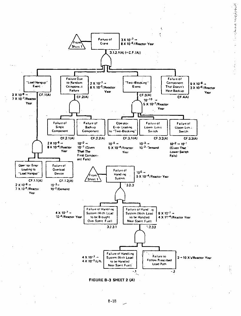
9 X 10"8 -3 X 10⁻⁶/Reactor
Year
2 X 10⁻⁶ - 7-37 X !O4 IReacor 10-2 /Dernand
Yea.
4 X 10( -7.0-4/Reacxor Year
8 X 10⁻⁷ _4 X 1l" 4 /Reactor Year
2 - 10 X's!Reactor Year
FIGURE B-3 SHEET 2 (A)
P-18
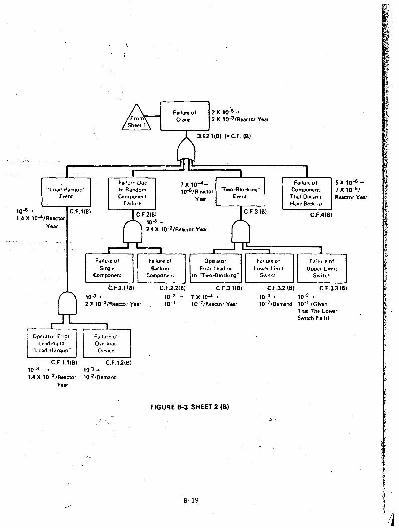
Far,,.rf Due 7 X 10- 1 Failure of 5 X 10⁻⁶ -"Load Hanqup" to Random 10-6/Re *-or "Two-Blocking" Component 7 X 10"5/Event Component Yew Event • That Doesn't Reactor Year
Failure Have Bac-k.o106.C.F.1(E) F.2B C..(B) CF4
1.4 X 10⁻⁴/Reacwr 1D4 CFF1..(
Year 2.4X O3IReactor' YeW
Failue of Failure of Operator Fziluieof Failuu'e 01Sirnle Backu p E-ror Leadinq Low, er Limit Upper Limit
Componerr / Componen, to /l wo-"lockng" Switch Switch
C.F1. .1(3) C.F.2.2(B) c.r.3.1(B) C.F.32 (B) C.F.3.3 (B)S10"- 10-2 7-X10-- 10-22102 /Reaco" Year 10-1 O-Reactor Year 10-2 /Dernand 10-1 (Given
That The Lower
Switch Fails)
Gperator Error Failure ofLeading to Overload
"Load Harnup" De ice
C.F.I.I(B) C.F.12(B)10-31
1.4 X 10- 2 /Reactor r0-2/DemandYear
FIGURE B-3 SHEET 2 (B)
B/ t
B- 19
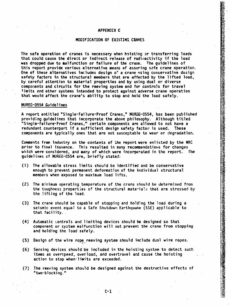
APPENDIX C
MODIFICATION OF EXISTING. CRANES
The safe operation of cranes is necessary when hoisting 3r transferring loadsthat could cause the dire:t or indirect release of radioactivity if the loadwas dropped due to malfunction or failure of the crane. The guidelines ofthis report provide various alternative means of assuring safe crane operation.One of these alternatives includes design o" a crane ,ising conservative designsafety factors in the structural members that are affected by the lifted load,by careful attention to material properties and by using dual or diversecomponents and circuits for the reeving system and for controls for travellimits end other systems intended to protect against adverse crane operationthat would affect the crane's ability to stop and hold the load safely.
NUREG-0554 Guidelines
A report entitled "Single-Failure-Proof Cranes," NUREG-0554, has been publishedproviding guidelines that incorporate the above philosophy. Although titled"Single-Failure-Proof Cranes," certain components are allowed to not have aredundant counterpart if a sufficient design safety factor is used. Thesecomponents are typically ones that are not susceptable to wear or degradation.
Comments from industry on the contents of the report were enlisted by the NRCprior to final issuance. This resulted in many recoamendatioiis for changeswhich were considered, and many of which were incorporated in the report. Theguidelines cf NUREG-0554 are, briefly stated:
(1) The allowable stress limits should be identified and be conservativeenough to prevent permanent deformation of the individual structuralmembers when exposed to maximum load lifts.
(2) The minimum operatirg temperature of the crane should be determined fromthe toughness properties of the structural materian that are stressed bythe lifting of the load.
(3) The crane should be capable of stopping and holding the load during aseismic event equal to a Safe Shutdown Earthquake (SSE) applicable tothat facility.
(4) Automatic :.ontrols and limiting devices should be designed so thatcomponent or system malfunction will not prevent the crane from stoppingand holding the load safely.
(5) Design of the wire rope reeving system should include du3l wire ropes.
(6) Sensing devices should be included in the hoisting system to detect suchitems as overspeed,.overload, and overtravel ard cause the hoistingaction to stop when limits are exceeded.
(7) The reeving system should be designed against the destructive effects of"two-blocking."
C-1

(8) The hoisting drum(s) should be protected against dropping should its Ashafts or bearings fail.
(9) Safety devices such as limit switches provided to reduce the likelihoodof a malfunction should be in addition to those normally provided forcontrol of maloperation or operator error.
(10) The crane system should be given a cold proof test if material toughnessproperties are not known.
As a result of public comments, the recommendations in the NUREG-0554 reportinclude some alternate solutions where a direct compliance with some of therecommendations would be difficult or impractical to follow. Furthermore, for N,some power plant layouts it may be acceptable to relax some safety feature ifan equivalent degree of safety can be obtained by adding other featurcs suchas a higher design safety factor for a load-bearing component.
Implementation of NUREG-0554 For Operating Plants
In the case of a new crane, all the recommendations contained in NUREG-0554should be followed; ;,owever, in the case of an existing crane that is to beupgraded to the guidelines of Section 5.1.6, space economies for the crane maynot allow ready application of all the safety features to the crane. Addi-tionally, application of certain other features may not be practical sincethey would require replacement of certain components whose adequacy can beverified by alternative measures. Thus, certain adjustments may be necessaryto compensate for those features that will not be included. The followingidentify alternatives that may be used for certain applications when upgradingan existing crane in lieu ef complying with certain recommendations of theNUREG-0554. .
(1) Paragraph 2.2 of NUREG-0554 recommends that the crane be designed to theMCL (Maximum Critical Load, defined in NUREG-0554) but that those componentparts that are subject to wear or degradation be designed to a greaterload to prevent the load-handling safety factor to drop below the MCLrating due to wear between maintenance periods. However,-a specificapplication was accepted in which the wear susceptible com.ponents weredesigned to the MCL rating and not to a greater load rating to allow forwear.
Although the recommendation to dedign certain components to a greaterload rating was not met, an equivalent margiii of safety was achievedbecause the drive gear contained a torque limiting device that with theproper setting effectively limits the load which the wire rope and otherwear susceptible components will experience. (NOTE: an overload sensingdevice that has been energized in order to stop the electric drive motorwould not have adequately accomplished this due to the time delay inherentin such a device).
(2) Paragraph 2.4 of NUREG-0554 recommends a coldproof test as an alternatemethod of assuring absence of brittle-fracture tendency in lieu of material Itesting for cranes that are already built and operating. For a modifiedcrane in an operating plant, the coldproof test was omitted because the
C-2

minimum ambient temperature was 70*F (21*C), which exceeded the NDTT +60*F requirehment (of paragraphs NC-Z300 and ND-2300 of Section III of theASKC Cz-de) foi most structural steels of comparable dimensicns (NDTT isthe "nil-duc+ility transition temperature"). :3
(3). Paragraph 2.8 of NUREG-0554 recommends that preheat and postweld heat--treatment temperatures be specified in thte weld procedure. For a modifiedcrane in an operating plant, the weldments may not have been hee." treatedin accordance with Subarticle 3.9 of AWS D1.i, "Structural Welding Code."As a substitute for weld heat treatment of crane structures already builtor-in-operation, the welds whose failure could result in the drop of acritical load should be nondestructively examined to ascertain that theweldments a-e acceptable.
(4) -Paragraph 4.1 of NUREG-0554 recommends that fleet angles in the wire ropereeving system be limited to' prevent excessive wear on the wire rope.Larger than recommended fleet angles have been accepted for an applicationwhere space limitation prevented the use of larger sheaves. However, a
- more -frequent. inspection program was included to assure the continuedintegrity of the wire rope.
(5) Paragraph 4.3 recommends that the load blocks have two attachment pointsor hooks. Because of an existing building height limitation and difficultyin getting sufficient lift height at one installation being upgraded tosingle-failure-proof criteria, a single attachaent sister hook was accepted.However, the safety factor was increased to 10:1 to compensate for lessof the- single-failure-proof feature and to equal the total safety factorfor the wire rope.
(,') Paragraph 4.9 of NUREG-0554 recommends that the hoist holding brakesystem be single-failure-proof. Normally the holding brakes are locatednear the motor drive in order to reduce the size of the brake unit, andconsequently the gears or transmissions interposed between the mrtor andthe hoist-drum must be of dual design to be single-failure-proof. Omissionof a second gear train has been accepted for cranes where two emergencybrakes were applied directly to the hoisting drum, thus eliminating ýheneed of the dual gear trains to provide assurance that the load will besafely held in case of a single failure.
(7) Paragraph 4.5 of NUREG-0554 recommends load hangup protection. However,a system of interlock circuitry preventiag movement of the trolley andthe bridge) while hoisting the load has been accepted in lieu of loadhangup prutlectior..
(8) Paragraph 8.3 of NUREG-0554 recommends that if the design includes ansnergy- controlling device between the load and head blocks a test be madeto verify the hoisting machinery's ability to withstand a "two-blocking"event.
As an alternative to designing to withstand a "two-blocking" event,Paragraph 4.5 of NUREG-0554 allows the crane to be furnished with twoindependent travel limit switchL-. If ttis alternative is selected, the'two-blocking" test should be verification of the proper functioning of
C-3
I

these switches. In addition, some cranes are furnished with a load-limitingdevice (e.g., strain gage, etc.) that will automatically protect thereeving system. If such a load limiting device is used, a substitute forthe "two-blocking" test may be made that demonstrates the proper functioningof the load limiter.
(9) Paragraph 8.3 of NUREG-0554 also recommends a load hangup test. Whereinterlock circuitry is provided in lieu of load hangup protection, testingshould be performed to verif:, the operability of the ir,..rlocks.
Impact
Non-single-failure-proof cranes already in use at operating plants typicallymeet several of the above guidelines or alternatives. Modification of exist-ing cranes to satisfy HUREG-0554 will vary from plant to plant but generallywill not require complete replacement of the crane. Modifications W~uldinvolve use of techniques and components that are readily available. Forcertain cranes to meet the guidelines or alternatives to NUREG-0554, modifi-cations may be limited to additior of a double reeving system to the existingtrolley. However, for other cranes, the entire trolley may need to be replaced.Such trulleys are commercially available as a retrofit unit, and at least onemanufacturer's unit may be disassembled so as to permit it being transferredinto areas with limited entrance sizes, such as a containment building equipmenthatch.
The cask handling cranes at several operating power plants have already beenupgraded orare planned to be upgraded to meet single-failure-proof criteriaas shown in Table 3.2-3 of Section 3.2.
Implementation of the guidelines of Section 5.1 will require that loads handledby PWR polar cranes and, at certain plants, loads handled by turbine buildingcranes be evaluated for potential consequences if dropped. If evaluationcriteria of 5.1 are not met, it may require that these cranes be upgraded atcertain plants to single-failure-proof criteria.
C-4

APPENDIX D
REFUELING OPERATIONS
CRANE TRAVEL - FUEL BUILDING
LIMITING CONDITION FOR OPERATION
3.9.7 Loads carried over the spent fuel pool and the heights at which theymay bE carried over racks containing fuel shall be limited in such a way as topreclude impact energies over 240,000 in.-IbF., if the loads are dropped.
APPLICABILITY: With fuel assemblies and water in the storage pool.
ACTION:
With the requirements of the above specification not satisfied, place thecrane load in a safe condition. The provisions of Specification 3.0.3 are notapplicable.
........SURVEILLANCE REQUIREMENTS
4.9.7 The potential impact energy due to dropping the crane's load shall bedeterzined to be less than or equal to 240,000 in.-lbs. prior to moving eachload over racks containing fuel.
TROJAN-UNIT I 3/4 9-7 Amendment No. 34
A

APPENDIX E
REFERENCES
A:. ANSI B30.2-1976, "Overhead and Gantry Cranes," The American Society ofMechanical Engineers, New York, NY.
2. ANSI 830.9-1971, "Slings," The American Society of Mechanical Engineers,New York, NY.
*3. ANSI N14.6-1978, "Standard for Special Lifting Devices for ShippingContainers Weighing 10,000 Pounds (4500 kg) or More for Nuclear Materials,"American National Standards Institute, New York, NY.
4. "Spec.fications for Electric Overhead Tr~velling Cranes," O4AA - 70 - 1975,(supersedes EOCI - Specification 61). .• .ilable from Crane ManufacturersAssociation of America, Pittsburgh, PA, copyrighted.
5. U.S. Nuclear Regulatory Commission, "Single-Failure-Proof Cranes forNuclear Piwer Plants," USNRC Report NUREG-0554, May 1979.*
6. U.S. Nuclear Regulatory Commission, "Standard Review Plan for the Reviewof Safety Analysis Reports for Nuclear Power Plants - LWR Edition," USNRCNUREG-75/087, Section 9.1.2, "Spent Fuel Storage."
7. U.S. Nuclear Regulatory Commission, "Standard Review Plan for the Reviewof Safety Analysis Reports for Nuclear Power Plants - LWR Edition," USNRCNUREG-75/087, Section 9.1.4, "Fuel Handling System."*
8. U.S. Nuclear Regulatory Commission, "Standard Review Plan for the Reviewof Safety Analysis Reports for Nuclear Power Plants - LWR Edition," USNRCNUREG-75/087, Section 13.1.3, "Qualifications of Nuclear Plant Personnel."*.
9. U.S. Nuclear Regulatory Commission, "Standard Review Plan for the Reviewof Safety Analysis Reports fcr Nuclear Power Plants - LWR Edition," USNRCNUREG-75/087, Section 15.7.4, "Radiological Consequences of Fuel HandlingAccidents.
10. U.S. Nuclear Regulatory Commission, Regulatory Guide 1.13, Revision 1,"Spent Fuel Storage Facility Design Basis.'**
11. U.S- Nuclear Regulatory Commission, Regulatory Guide 1.25, "AssumptionsUsed for Evaluating the Potential Consequences of a Fuel Handling Accidentin the Fuel Handling and Storage Facility for Boiling and PressurizedWater Reactors.""
12. U.S. Nuclear)Regulatory Commission, Regulatory Guide 1.33, "QualityAssurance Program Requirements (Operation)."*1
* Available for purchase from GPO Sales Program, U.S. Nuclear.'RegulatoryComission, Washington, D.C. 20555 and/or National Technical InformationService, Spifingfield, Virginia 22161.
• Available for purchase from GPO Sales Program, U.S. Nuclear Regulatory Commission,Washington, D.C. 20555. A
E-i