of a Full-Coverage-Film-Cooled Vane or Blade
93
NASA AVRADCOM Technical Paper 1259 Technical Report 78-19(PL) FORTRAN Program for Calculating Coolant Flow and Metal Temperatures of a Full-Coverage-Film-Cooled Vane or Blade Opy Peter L. Meitner JULY 1978 NASA
Transcript of of a Full-Coverage-Film-Cooled Vane or Blade

NASA AVRADCOMTechnical Paper 1259 Technical Report 78-19(PL)
FORTRAN Program for CalculatingCoolant Flow and Metal Temperaturesof a Full-Coverage-Film-Cooled
Vane or Blade
OpyPeter L. Meitner
JULY 1978
NASA

NASA AVRADCOMTechnical Paper 1259 Technical Report 78-19(PL)
FORTRAN Program for CalculatingCoolant Flow and Metal Temperaturesof a Full-Coverage-Film-CooledVane or Blade
Peter L. MeitnerPropulsion Laboratory, AVRADCOM Research and Technology LaboratoriesLewis Research CenterCleveland, Ohio
NASANational Aeronauticsand Space Administration
Scientific and TechnicalInformation Office
1978

CONTENTSPage
SUMMARY 1
INTRODUCTION 2
METHOD OF ANALYSIS 3Geometry and Terminology 3Assumptions 3Flow Analysis 4
Vane 4Blade 5
Heat-Transfer Analysis 6
PROGRAM INPUT 7Title Card 8Tabular Input Cards 8Chamber Input Cards 9
PROGRAM OUTPUT 10Units and Option Messages 11Impingement Hole Input Data 12Film-Cooling Hole Input Data 12Impingement Flow Results 13Film -Cooling Flow Results 13Heat-Transfer Results 14Error Messages 16
Main program 16Subroutine TMETO 17Subroutine MNEW 17Subroutine SPLINE 17
EXAMPLE PROBLEMS 17Example 1 18Example 2 18
APPENDICESA - SYMBOLS 19B - EQUATIONS 22C - DERIVATION OF EQUATIONS FOR METAL TEMPERATURE DISTRIBU-
TION AND COOLANT TEMPERATURE RISE IN A TWO-LAYERPOROUS WALL 29
iiiPreceding Page Blank

D - PROGRAM STRUCTURE AND FUNCTION 35E - PROGRAM VARIABLES DICTIONARY 37F - PROGRAM LISTING 50
REFERENCES 74
iv

FORTRAN PROGRAM FOR CALCULATING COOLANT FLOW AND
METAL TEMPERATURES OF A FULL-COVERAGE-
FILM-COOLED VANE OR BLADE
by Peter L Meitner
Propulsion LaboratoryU. S. Army R&T Laboratories (AVRADCOM)
SUMMARY
A FORTRAN computer program called FCFC has been developed that calculates thecoolant flow and the wall temperatures of a full-coverage-film-cooled vane or blade.Coolant flow is treated as one-dimensional and compressible. Heat transfer to the cool-ant due to impingement on the shell inner surface and convection in the film-cooling holesis calculated. Coolant supply pressures and main-stream gas static pressures can varyfrom hole row to row, and centrifugal effects can be included for blade calculations.Heat-transfer calculations can be excluded so that the program can be used as a flowprogram only.
The vane or blade metal temperatures are calculated for the shell inner and outersurfaces. All these temperatures are average values for a shell outer-surf ace area as-sociated with each film-cooling hole row. The heat-transfer calculations are one-dimensional through the wall and neglect conduction from adjacent areas. A thermal-barrier coating may be specified on the shell outer surface. With this option, the pro-gram also calculates the interface temperature between the metal and the ceramiccoating.
The program input is the chamber geometry (hole sizes, hole spacings, etc.); cool-ant supply temperature and pressures; and main-stream gas heat-transfer coefficients,pressure, and velocity and temperature distributions. The physical properties of thecoolant and the thermal conductivities of the metal and the ceramic coating are input asfunctions of temperature. The coolant flow coefficients for the impingement and film -cooling holes are input as functions of Mach number. The program output is a summaryof the geometric data and the calculated coolant-flow and heat-transfer results.
This report presents the analytical procedure and identifies the necessary assump-tions. It describes program input and output, explains error messages, illustrates twoexamples, and provides a program listing.

INTRODUCTION
Full-coverage film cooling is a very effective scheme for protecting turbine com-ponents from the hostile operating environment of high main-stream gas temperature andpressure. Full-coverage film cooling permits higher operating temperatures and pres-sures than convection cooling for greater overall cycle efficiency (lower specific fuelconsumption) at acceptable coolant flow rates (ref. 1). For maximum effectiveness,compressor discharge air is first impinged on the inner surface of the vane or bladeshell to remove heat by convection (ref. 2). The cooling air is then bled out through alarge number of evenly distributed holes in the shell. The coolant forms a continuous,relatively cool, insulating layer between the shell outer surface and the hot main-streamgas.
Numerous experiments and analyses of various aspects of full-coverage film coolinghave appeared in the open literature, and the analysis of this report is based in part onthe results of references 3 to 6. Reference 3 approximates full-coverage film cooling asa form of transpiration cooling and derives the equations for metal and coolant temper-ature distribution for specified coolant flow, specified shell outer-surf ace temperature,and specified back-side-impingement and internal-wall heat-transfer coefficients. Ref-erence 4 describes a computer program that calculates the heat-transfer coefficients fora turbulent boundary layer on a porous wall and reference 5 describes a discrete-holeblowing model for full-coverage film cooling. Reference 6 establishes flow coefficientsfor a typical full-coverage-film-cooled geometry.
Although these reports describe many aspects of full-coverage film cooling, theseaspects have not been combined into an overall analytical procedure. Such a procedurehas been developed and is reported herein. The coolant flow and the wall and coolanttemperature distributions are calculated for a given vane or blade geometry; given cool-ant supply temperature and pressure; and given main-stream gas heat-transfer, tem-perature, pressure, and velocity conditions. Heat and flow balances are performed foreach specified row of film-cooling holes and its associated portion of the shell outer sur-face. The flow and heat-transfer equations are solved simultaneously on the basis ofcompressible, one-dimensional fluid flow and one-dimensional heat transfer. For theheat-transfer calculations the equations of reference 3 are expanded and modified for atwo-layer model to allow the inclusion of a thermal-barrier coating. Centrifugal pump-ing effects are included for blade calculations.
The computer program is in FORTRAN IV and is operational on a UNTVAC 1100/42computer. The program consists of 1650 cards and occupies 22 500 36-bit words ofmemory. Its execution time is typically less than 15 seconds.
This report explains the analytical procedure used to develop a computer programcalled FCFC (full-coverage film cooling), which performs the described calculations.

The report lists the formulas used, identifies the necessary assumptions, describes therequired program input, illustrates two examples, discusses the program output, ex-plains the program error messages, and provides a program listing.
METHOD OF ANALYSIS
Geometry and Terminology
Figure 1 shows a section of atypical full-coverage-film-cooled blade. Internalribs, together with an insert, divide the blade cross section into individual chambers.The large variations in main-stream gas pressure and velocity around the airfoil periph-ery make chambers necessary to control and meter the coolant flow at the most advan-tageous local mass flux ratio, m = (pVL/(pV) . (All symbols are defined in appendix A.)The analysis described herein is for a single chamber in a vane or blade. The entirevane or blade is analyzed by performing the calculations for every chamber in that vaneor blade.
Figure 2 shows a cross section of a chamber and identifies the coolant flow stations.Station 1 is the supply plenum, station 2 is the impingement orifice plane, station 3 isthe impingement plenum, and stations 4 and 5 are the inlet and outlet of the film-coolingholes, respectively. Station 6 is the main-stream gas flow immediately adjacent to theshell outer surface. For subsonic flow through the film-cooling holes, the static pres-sures at stations 5 and 6 will be equal. For sonic flow, however, the static pressurewill be greater at station 5 than at station 6.
The film-cooling holes in the shell are oriented by the angles a and /3, as shownin figure 3. The angle a is formed by the hole centerline and its projection in the tan-gent plane. The angle |3 lies in the tangent plane and is measured from a chordwiseline through the hole centerline and its projection in the tangent plane. An angle of/3 = 0° implies in-line holes (alined in the main-stream gas flow direction), whilej3 = 90° implies radially oriented (spanwise) holes.
Assumptions
The flow and heat-transfer calculations of this analysis are performed with the fol-lowing assumptions:
(1) Coolant flow is one-dimensional from the supply plenum into the main-streamgas.
(2) For a rotating blade, the radial pressure variation in the impingement plenumis that of a stationary column of air under the influence of a rotating field.

(3) For a rotating blade with compound -angle holes (/3 > 0 and hole entrances andexits at different radial locations), the pressure changes in the film-cooling holes due tocentrifugal pumping are much less than the normal pressure drop across the holes.
(4) Each film-cooling hole row cools only its associated area of shell outer surface.(5) Heat transfer is one-dimensional through the vane or blade shell (stations 4 to 5).
Calculations are performed for each specified row of film-cooling holes (including back-side impingement and convective heat transfer in the holes), but conduction between ad-jacent rows is neglected.
(6) The calculated back-side impingement heat-transfer coefficients are averagedover the entire inner surface (back side), of the shell. Specific impingement rows arenot associated with specific film-cooling rows, or conversely.
Flow Analysis
Overall balanced coolant flow can exist through a full-cover age-film-cooled chambereven if one or more holes have reverse flow, that is, for example, if main-stream gasflow travels from station 5 to station 4 in the film -cooling holes or coolant flow travelsfrom station 3 to station 1 in the impingement holes. However, such a situation is un-acceptable from a design standpoint since any inflow of hot main-stream gas will renderthe design useless. Therefore, the flow analysis does not allow reverse flow. The de-tailed flow equations are presented in appendix B.
For a given vane or blade chamber, the main-stream static pressures (station 6)can vary in the chordwise, as well as in the spanwise, direction. For a vane the coolantpressure in the impingement plenum (station 3) will be constant, but for a rotating bladethis pressure will vary in the radial direction. For proper flow balancing, therefore,each chamber in a vane or blade must be subdivided into either spanwise or chordwiserows of impingement and film-cooling holes, as shown in the following sections.
Vane. - Figure 4 shows the outline of a typical full-coverage-film-cooled vane andone of its pressure-side chambers, which has been divided into rows of impingementholes and film-cooling holes with associated shell outer-surface areas. Each shell areais assumed to be cooled solely by the coolant flow through the holes within that area. Avane impingement row consists of one or more equal-size impingement holes that have acommon supply pressure. A vane film-cooling row consists of one or more equal-sizefilm-cooling holes and the associated shell outer-surface area, which has constant main-stream gas temperature, pressure, and heat-transfer coefficients acting over its sur-face. A vane chamber can be divided into either spanwise or chordwise rows of holes,as illustrated in figure 4.

Before the coolant impingement inflow and film-cooling outflow can be calculated,the pressure in the impingement plenum (station 3) must be known. However, in any de-sign, only the supply pressures (station 1) and the main-stream gas static pressures(station 6) are known. The impingement plenum pressure for balanced coolant inflow andoutflow must be obtained in an iterative manner as follows: Avoiding reverse flow at theimpingement and film-cooling holes requires that the impingement plenum pressure beless than the lowest specified impingement supply pressure and more than the highestspecified main-stream gas static pressure. Initially, the plenum pressure is taken to bethe average of these pressures, and the coolant inflow and outflow are calculated. If theresulting outflow is greater or less than the inflow, the plenum pressure is decreased orincreased, respectively, in the next flow iteration. The procedure is continued until theinflow and outflow are within a relative tolerance of 0.1 percent.
Blade. - Figure 5 shows the outline of a typical full-coverage-film-cooled blade andone of its pressure-side chambers, which has been divided into chordwise rows of im-pingement holes and film-cooling holes with associated shell outer-surface areas. Asfor the vane, each shell area is assumed to be cooled solely by the coolant flow throughthe holes within that area. A blade impingement row consists of one or more equal-sizeimpingement holes that have a common supply pressure as well as a common radial lo-cation (distance from shaft centerline). A blade film -cooling row consists of one or
, more equal-size film-cooling holes at a common radial location and the associated shellouter-surface area, which has constant main-stream gas temperature, pressure, andheat-transfer coefficients acting over its surface. A blade may be divided only intochordwise impingement and film-cooling rows of holes, as shown in figure 5.
In a rotating blade, the pressures in the supply and impingement plenums (stations 1and 3, respectively) will vary from hub to tip. The radial supply pressure distributionmust be specified and the resulting impingement plenum pressure distribution determinedto calculate the coolant flow through the blade. Since there will be many rows of im-pingement and film-cooling holes along the span, the coolant flow from station 1 to sta-tion 6 will be essentially one-dimensional, with little distance traveled in the radial di-rection. The radial pressure variation in the impingement plenum can thus be assumedto be that of a stationary column of coolant under the influence of a rotating field. For agiven pressure at a specific radial station (pQ at station TQ), the pressure at any otherradius r is given by
p(r) = pQ exp2RTgc
An allowable range of base pressure is established at the minimum specified radius suchthat no reverse flow can occur at any impingement or film -cooling row. The total coolant
inflow and outflow are then balanced by the iterative procedure described previously fora vane, with the impingement plenum pressure at each impingement and film-cooling rowcalculated by the preceding equation.
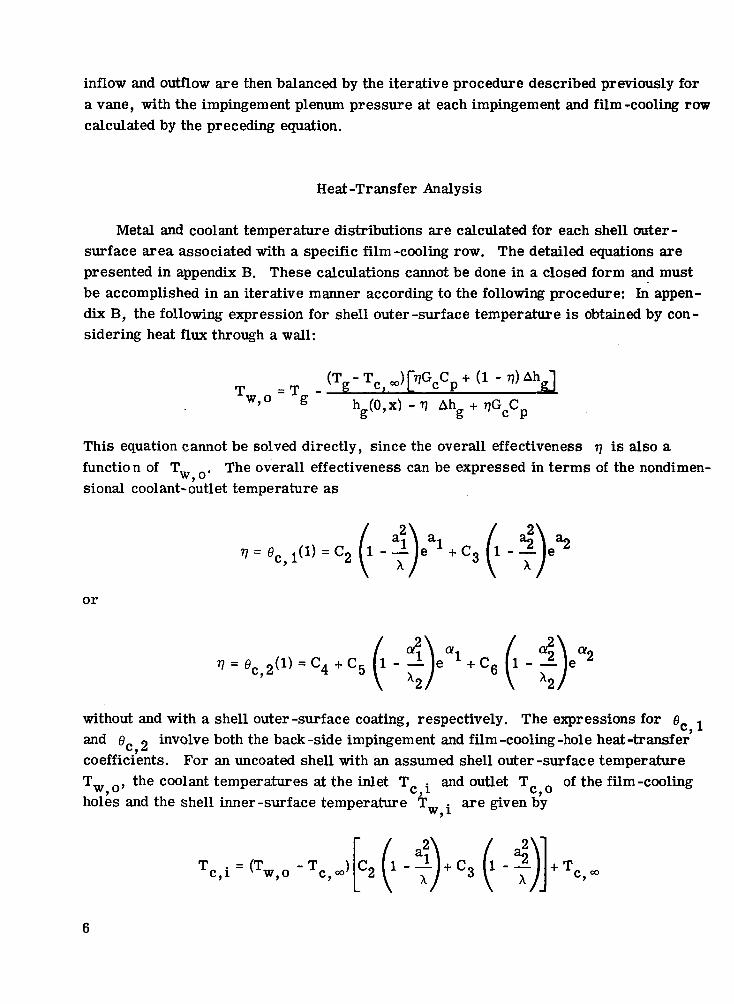
Heat -Transfer Analysis
Metal and coolant temperature distributions are calculated for each shell outer -surface area associated with a specific film -cooling row. The detailed equations arepresented in appendix B. These calculations cannot be done in a closed form and mustbe accomplished in an iterative manner according to the following procedure: In appen-dix B, the following expression for shell outer -surf ace temperature is obtained by con-sidering heat flux through a wall:
= T(T -T JfVjG C +(1 - T j ) A h-- 2 _ LL — L — c V -
h g (0 ,x ) -Tj
This equation cannot be solved directly, since the overall effectiveness TJ is also afunction of T . The overall effectiveness can be expressed in terms of the nondimen-sional coolant-outlet temperature as
17 = flc> !(« = C2 1-
or
without and with a shell outer-surf ace coating, respectively. The expressions for fl 1c, iand 0 9 involve both the back-side impingement and film-cooling-hole heat-transferi/,^coefficients. For an uncoated shell with an assumed shell outer-surface temperatureTiir r» the coolant temperatures at the inlet T. = and outlet T. n of the film-coolingw,u c, i c,oholes and the shell inner-surf ace temperature T . are given by
T . = (T - T )c,i v w,o c,°°' + T.

T = TJ (T -T ) + Tr> n ' V iw n ± n oo' Tc,o W,O C,°o'
For a coated shell, the coolant temperature at the film-cooling hole inlet T ., at theinterface between the metal and the coating T if, and at the film-cooling hofe outletc, iiT • the shell inner-surf ace temperature T .; and the interface temperature T .,
^ j " iV • A W * LA
are given by
T = (T Tc,if v w,o ~ + T,
w,if ~ T
The overall iterative solution scheme is illustrated by the flow diagram of figure 6.Equation numbers for cases with a thermal-barrier coating are marked with an asterisk.The impingement and film -cooling hole heat -transfer coefficients are functions of thecalculated wall temperatures or coolant temperatures (through the physical properties)as indicated. The procedure of figure 6 is performed for every row of film -cooling holesat every flow -balancing iteration. The generated value of coolant -outlet temperatureT- affects the density and thus the calculated weight flow in the next flow iteration.
\s • \J
PROGRAM INPUT
The input to FCFC consists of a title card, a series of tabular input cards, and aseries of cards describing each chamber to be analyzed. The tabular inputs are the onlyformatted data input. The data for each specific chamber are input in NAMELIST form.

An input data form is shown in table I. The required input cards are the title card, thetabular input cards, and the chamber input cards.
Title Card
The title card must always be present and is used to identify the particular set ofruns. All 80 columns can be used.
Tabular Input Cards
The tabular input cards describe the required coolant and material physical prop-erties, as well as the coolant flow coefficients. Each set consists of three or morecards as follows:
Card 1: NP in 12 format, where NP is the number of points in the tableCards 2 a, 2b, 2c: the NP x -values describing the table in ascending order and in
8F10.0 format (a maximum of 24 points)Cards 3a, 3b, 3c: the corresponding NP y -values in 8F10. 0 format
The tables to be input, along with the required SI or U. S. customary units, are shown intable H.
Tables 1 to 6 must always be supplied. Tables 7 and 8 can be deleted if there is nomain -stream flow; tables 9 and 10, if no heat -transfer calculations are to take place(FCFC used for flow analysis only); and table 10, if there is no ceramic coating. Todelete a table, input zero in card column 2 of the NP card. The tables of impingement-hole discharge coefficient (CD)., film- cooling hole total- pressure loss coefficient(KT) , and film-cooling hole flow reduction due to main-stream gas flow RT (tables5, 6, and 7, respectively) are given in reference 6. The program flow calculations arebased on flow coefficients as defined in reference 6. The impingement -hole dischargecoefficient (CD) is defined as the ratio of actual to ideal flow, the film- cooling hole total -pressure loss coefficient is defined as
and the film -cooling hole flow reduction due to main -stream gas flow is defined as
Actual coolant flow with main-stream gas flowCalculated coolant flow with no main-stream gas flow

The RT values of reference 6 are for a compound film-cooling hole angle ft of 0°.Table 8 is used to correct RT for other values of /3 (from 0° to 90°).
The program FCFC generates a spline curve fit from each inputted set of tabulardata. The curve-fitting procedure requires the slopes at the end points. These slopesare calculated from the first two and last two data points. For this reason, these pointsshould be chosen such that fairing a straight line between them gives a good approxima-tion to the slope of the curve at the end points. For all tables, at least three input pointsare needed. If the program calls for a value at an x-location outside the range of the in-put table, the value at the nearest end point is used and an appropriate warning messageis printed out.
The input coordinates for table 8 are rotated through an angle of 45°, arid the splinefitting takes place in the rotated coordinate system. This gives a better curve fit fordata with rapid changes in slope such as occur in input table 8.
Chamber Input Cards
The data for each chamber are preceded by $DATT, which is punched starting incard column 2. The variable names (starting in card column 2 or beyond) are followedby an equal sign and the value or values of the variable, separated by commas. Foreach chamber, the number of impingement hole rows NIR and the number of film-coolinghole rows NFCR are specified; the maximum allowable rows are 25 and 50, respectively.Subscripted variables are associated with specific rows; that is, the N subscriptedvalue is associated with the N row of holes. When fewer than the maximum number ofrows are specified, subscripted variables need only have as many input values as thespecified number of rows. Integer values must be input without decimal points. Thelast data value for each chamber is followed by a $ instead of a comma. The input dataare retained for multiple chamber inputs. Thus, if a variable is common to successivechambers, it has to be input just once for the initial chamber. The chamber geometryinput variables are defined by figure 7. All chamber input variables, along with the re-quired SI or U. S. customary units, are shown in table in.
The variables IUNTS to OMG in table m specify the types of calculations desired.These variables have been assigned default values as shown. The variables NIR to RGASare associated with the impingement hole rows: NIR is the number of specified impinge-ment hole rows, and NIHPR to PIT are subscripted variables associated with the im-pingement rows. As such, each variable must have at least NIR input values. The var-iable HSP1, the hole spacing for each impingement row, is used in determining the back-side impingement heat-transfer coefficient (eq. (Bll)). This correlation is based on asquare impingement array, with equal spacings in the spanwise and chordwise directions,as shown in figure 7. In practice, however, these spacings may differ and the average

of the two spacings should then be specified. The variables TT and EGAS define thecoolant gas; they are not subscripted and are thus constant for all rows of impingementholes.
The variables NFCR to ROV2G of table m are associated with the film-cooling holerows. The variable NFCR is the number of specified film-cooling hole rows, andNFCHPR to ROV2G are subscripted variables that must have at least NFCR values. Thevariable HSP5 is the hole spacing for each film-cooling hole row (fig. 7), and,' as forHSP1, an unequal array spacing should be reduced to an equivalent square spacing. Thevariable HFC4 (h factor at station 4; fig. 2) is a modification factor for the calculatedimpingement heat-transfer coefficient at each film-cooling hole row. For the film-cooling heat-transfer calculations, the calculated impingement heat-transfer coefficientsare averaged over the shell back side (inner surface), since the program does not asso-ciate specific impingement rows with certain film-cooling-hole rows, or conversely.When back-side heat-transfer coefficients vary (from centrifugal effects or from im-pinging at less than perpendicular to the surface), HFC4 is a multiplier used to modifythe back-side heat-transfer coefficient at the specified film-cooling-hole rows. (Thisvariable has a default value of 1.0.) The variable HFC45 (h factor for stations 4 to 5;fig. 2) is a multiplier used to modify the calculated film-cooling hole heat-transfer co-efficients for each row (eq. (B13)). Equation (B13) is valid for hole length-diameterratios L/D between 1.0 and 8.0. For L/D less than 1.0, reference 7 measured heat-transfer coefficients that were as much as 50 percent greater than predicted by equa-tion (B13) (entrance effects). The correction factor HFC45, which has a default value of1.0, is used to account for this. The variable TMSG is the main-stream gas temper-ature, which must be the same as the temperature used to evaluate the main-stream gasheat-transfer coefficients.
PROGRAM OUTPUT
The FCFC output is a printout of the title card, the input data for all specified tables,and the calculated results for each chamber. The chamber output consists of the follow-ing messages and blocks of tabulated data:
OUTPUT FOR CHAMBER XX
Units and Option Messages
XX ROWS OF IMPINGEMENT HOLES
Impingement Hole Input Data
10

XX ROWS OF FILM COOLING HOLES
Film-Cooling Hole Input Data
IMPINGEMENT AND FILM COOLING FLOWS HAVE CONVERGED IN
XX OVERALL ITERATIONS
INFLOW EQUALS XXXXX.XXX KG/HR (LBM/HR)
Impingement Flow Results
OUTFLOW EQUALS XXXXX.XXX KG/HR (LBM/HR)
Film-Cooling Flow Results
HEAT TRANSFER RESULTS
Heat-Transfer Results
Each of these blocks is described in the following subsections.
Units and Option Messages
One or more of the following messages about the system of units and the particularoptions used are printed out:
SI (ENGLISH) SYSTEM OF UNITS
COOLANT GAS CONSTANT - XXXXXX.XX J/(KG-K) ((FT-LBF)/(LBM-R))
THIS CASE IS FLOW ANALYSIS ONLY AND INCLUDES NO METAL TEMPERATURECALCULATIONS
THIS CASE INCLUDES A THERMAL BARRIER COATING
THIS CASE INCLUDES CENTRIFUGAL EFFECTS. ROTATIONAL SPEED ECUALSXXXXX.XX RPM
11

Impingement Hole Input Data
This block of output tabulates the following for each row of impingement holes:
ROW impingement row number
HOLES number of holes per row
DIAMETER hole diameter, mm; in.
impingement wall thickness, mm; in.THICKNESS
L/D hole length-diameter ratio
HOLE SPACING hole spacing, mm; in.
IMPINGEMENT impingement distance) mm; in.DISTANCE
Rl distance from shaft centerline, mm; in.o
PIT supply total pressure, N/cm ; psia
For noncentrifugal calculations, Rl is printed as zero.
Film -Cooling Hole Input Data
This block of output tabulates the following for each row of film-cooling holes:
ROW row number
HOLES number of holes per row
DIAMETER hole diameter, mm; in.
THICKNESSWALL wall metal thickness, mm; in.COATING coating thickness, mm; in.
L/D hole length-diameter ratio
HOLE SPACING hole spacing, mm; in.
ALPHA hole chordwise inclination angle
BETA hole compound inclination angle2 2RHOVG main-stream gas value of pV, kg/m -hr; Ibm/ft -hr
9 2 2RHOV2G main-stream gas value of pV , kg/m-hr ; Ibm/ft-hr
12

R4 distance from shaft center-line, mm; in.2
P6 main-stream gas static back pressure, N/cm ; psia
The L/D is that value associated with the combined thickness of the wall and any speci-
fied coating. When no main-stream flow is specified (MSBL=0), main-stream gas
RHOVG and RHOV2G are printed as zero. The variable R4 is the location of the film-
cooling hole centerline on the shell inner surface. For noncentrifugal calculations, R4
is printed as zero.
Impingement Flow Results
This block of output tabulates the following for each row of impingement holes:
IMP ROW row number2
PSPLYT coolant supply total pressure, N/cm ; psia2
P2 static pressure, N/cm ; psia
M2 Mach number
T2T total temperature, K; °F
T2 static temperature, K; °F
WIMP coolant inflow, kg/hr; Ibm/hr
CDIMP impingement discharge coefficient
The coolant supply total pressure, shown as PIT in the section Impingement Hole Input
Data, is repeated here as PSPLYT.
Film -Cooling Flow Results
This block of output tabulates the following for each row of film-cooling holes:
FC ROW row number2
P3T impingement plenum pressure, N/cm ; psia2
P4 static pressure at inlet, N/cm ; psia
M4 Mach number at inlet
T4T total temperature at inlet, K; °F
T4 static temperature at inlet, K; °F2
P5T total pressure at exit, N/cm ; psia
13

P5
M5
T5T
T5
TCTIF
WOUT
KT
RT
RTCORR
RHOVRATIO
RHOVSQRATIO
ITRS
static pressure at exit, N/cm ; psia
Mach number at exit
total temperature at exit, K; °F
static temperature at exit, K; °F
total coolant temperature at metal-coating interface, K; °F
coolant outflow, kg/hr; Ibm/hr
total-pressure loss coefficient
reduction in coolant flow due to main-stream flow
correction factor for RT
ratio of coolant-to-main-stream density times velocity
ratio of coolant-to-main-stream density times velocity squared
number of iterations needed to achieve film-cooling flow convergencein last overall flow iteration
When no coating is specified (KCLC=0), the coolant interface total temperature printszeros. When no main-stream flow is specified (MSBL=0), the pV and pV ratios printzeros and RT and RT CORR print 1. 0. The main-stream pressure, shown as P6 in thesection Film-Cooling Hole Input Data, is repeated here as P5. If the flow through thefilm-cooling holes is subsonic, P5 and P6 will be equal. However, for choked flow, P5will be that pressure determined from the compressible-flow relations at Mach 1. 0 andwill be greater than the specified main-stream pressure P6.
Heat -Transfer Results
This block of output tabulates the following for each row of film -cooling holes:
FC ROW row number
HEAT TRANSFERCOEFFICIENTS:
HGO main -stream gas heat -transfer coefficient for coolant temperature2 9equal to main-stream gas temperature, J/m -sec • K; Btu/ft •
hr-°R
14

HG1
FC-HOLE
IMPG
H MODIFICATION
FACTORS:
FC -HOLE
IMPG
COOLED AREA
GAS TEMP
WALL TEMP-
ERATURE:
OUTSIDE
INT FACE
INSIDE
AVG. THERM.
COND.:
METAL
COATING
ETA
ITR
main-stream gas heat-transfer coefficient for coolant temperatureo e\
equal to shell outer-surface temperature, J/m -sec • K; Btu/ft
h r - ° R
heat-transfer coefficient in film-cooling hole, J/m • sec-K;Btu/ft2 • hr • °R
2back-side impingement heat-transfer coefficient, J/m • sec-K;
Btu/ft2 • hr • °R
modification factor for film-cooling hole heat-transfer coefficient
(inputted HFC45)
modification factor for back-side impingement heat-transfer coeffi-
cient (inputted HFC4)
2 2cooled area associated with each film-cooling row, cm ; in.
main-stream gas temperature, K; °F
shell outer-surface temperature, K; F
shell interface temperature, K; F
shell inner-surface temperature, K; °F
metal average thermal conductivity, J / 'cm-sec-K: Btu/ft-hr- R
coating average thermal conductivity. J 'cm- sec- K: Btu/ft- hr- °R
overall effectiveness
number of iterations required to achieve metal temperature con-
vergence in last flow iteration
The tabulated values of film-cooling hole and impingement heat-transfer coefficients
include their corresponding modification factors. When no coating is specified (KCLC=0).
the interface temperatures and coating thermal conductivities are set to zero. The aver-
age thermal conductivities for the metal and coating are evaluated at the average temper-
atures through the metal and coating, respectively.
15

Error Messages
Error messages have been incorporated in the calculation procedure. The messagesfor the main program and the various subroutines, along with possible causes and cor-rective actions, are as follows (where error messages that do not stop program execu-tion are preceded by the word "WARNING"):
Main program. - The error messages for the main program are
CASE ABORTED - A REQUIRED CURVE WAS NOT INPUT OR WAS SPECIFIEDBY LESS THAN 3 POINTS
Check the required input tables and add the missing data or specify at least three points.
CASE ABORTED - COATING WAS SPECIFIED BUT NO COATING THICKNESS
Specify coating thickness.
CASE ABORTED - THE SPECIFIED PRESSURES WILL RESULT IN REVERSEFLOW
Check the specified supply and back pressures or alter hole sizes.
WARNING - T2 HAS NOT CONVERGED IN 15 ITERATIONS FOR IMPINGEMENTROW XX
This message could be caused by specifying significantly erroneous physical properties.
WARNING - T5 HAS NOT CONVERGED IN 15 ITERATIONS FOR FILM COOLINGROW XX
WARNING - T5T HAS NOT CONVERGED IN 15 ITERATIONS IN OVERALLFLOW ITERATION XX
These messages could be caused by specifying significantly erroneous physical prop-erties or the heat-transfer-coefficient modification factor HFC45.
WARNING - THE AVERAGE PRESSURE BETWEEN STATIONS 4 AND 5 HAS
NOT CONVERGED IN 15 ITERATIONS FOR FILM COOLING ROWXX
WARNING - P5T HAS NOT CONVERGED IN 15 ITERATIONS FOR FILMCOOLING ROW XX
These messages could be caused by specifying significantly erroneous physical prop-erties or the total-pressure loss coefficient curve (KT) .
IMPINGEMENT AND FILM COOLING FLOWS HAVE NOT CONVERGED IN
25 ITERATIONS
Change hole sizes and/or supply and back pressures.
16

Subroutine TMETO. - The error message for subroutine TMETO is
WARNING - OUTER WALL TEMPERATURE HAS NOT CONVERGED IN 15ITERATIONS IN OVERALL FLOW ITERATION XX
This error message can be caused by specifying erroneous values of the main-streamgas heat-transfer coefficients HGO and HG1. The message can also be caused by theinitial values assumed in the iterative process. If the message appears for values ofoverall flow iteration that are less than the actual number of flow iterations required(given by the message "IMPINGEMENT AND FILM COOLING FLOWS HAVE CON-VERGED IN XX OVERALL ITERATIONS"), the solution is valid.
Subroutine MNEW. - The error message for subroutine MNEW is
WARNING - M HAS NOT CONVERGED IN 25 ITERATIONS
Check the inputted table of total-pressure loss coefficient (KT)nm(T-
Subroutine SPLINE. - The error messages for subroutine SPLINE are
WARNING - A SPECIFIED X-VALUE (XXXXX.XXX) IS BELOW THE RANGEOF INPUT TABLE XX
WARNING - A SPECIFIED X-VALUE (XXXXX.XXX) IS ABOVE THE RANGEOF INPUT TABLE XX
Check the inputted tables and extend their range as required.
EXAMPLE PROBLEMS
The use of FCFC is illustrated by analyzing a chamber on both the vane and blade ofa high -temperature, high-pressure core turbine. Example 1 demonstrates flow and heat-transfer calculations for a vane chamber with a thermal -barrier coating. Example 2demonstrates centrifugal flow calculations without heat transfer and thus shows howFCFC can be used as a flow program only.
The inputted tables of impingement discharge coefficient (CD)., film -cooling holetotal-pressure loss coefficient (KDjun and film -cooling hole flow reduction due tomain-stream gas flow RT were obtained from reference 6. The main-stream gas heat-transfer coefficients HGO and HG1 were evaluated by using the Stanford UniversitySTAN5 computer program of reference 4 which was modified to include the discrete-holeblowing model of reference 5.
17

Example 1
A section of the vane and chamber that were analyzed is shown in figure 8. Alsoshown are the impingement hole diameters; the film-cooling hole diameters; the main-stream gas pressures P6; and the associated main-stream gas values of pV, pV , HGO,and HG1. The vane material is MAR-M509 and the coating is yttria-stabilized zirconia(YnOo-ZrOg). The vane span is 3. 81 centimeters (1. 50 in.), and the impingement andfilm-cooling hole spacings are 0. 381 and 0. 254 centimeter (0. 15 and 0. 10 in.), respec-tively. The shell and thermal-barrier coating thicknesses are 0. 127 and 0. 0127 centi-meter (0. 050 and 0. 005 in.), respectively, with an impingement distance of 0. 0889 centi-
f\meter (0. 035 in.). Coolant supply pressure is 404 N/cm (586 psia) and coolant tem-perature is 811 K (1000° F). Main-stream gas hot-spot temperature is 2550 K(4130° F).
Example 2
A section of the blade and chamber that were analyzed is shown in figure 9. Theblade span and the impingement and film-cooling hole spacings are the same as for thevane of example 1. Impingement and film-cooling hole sizes are constant at 0.4318 and0. 4572 millimeter (0. 017 and 0. 018 in.), respectively. For this example, which in-volves no heat-transfer calculations, the wall thickness and the impingement distanceswere taken to be constant at 1. 016 and 0. 762 millimeter (0. 040 and 0. 030 in.), respec-tively. In the actual blade, both vary from hub to tip. Coolant supply temperature was811 K (1000° F). The analysis was further simplified by assuming an impingement andfilm-cooling row at each of 15 specified radial locations. (In general, impingement andfilm-cooling rows are staggered.) Also, each film-cooling row was taken to consist oftwo adjacent holes (one from each chordwise station) and was assumed to have a radialposition equal to the average radial position of the two holes (fig. 9). The radial varia-tions of coolant supply pressure PIT and main-stream gas values of static pressure P6,
opV, and pV for the 15 rows are tabulated in figure 9.
Table IV lists the input data for the two example problems. The title card, the tab-ular inputs, and the chamber inputs are identified. Tables V to VII show the programoutput for the two examples. Table V shows the title card and all tabular data. TablesVI and VTI are the outputs for the vane and blade chambers, respectively.
Lewis Research Center,National Aeronautics and Space Administration,
Cleveland, Ohio, March 22, 1978,505-04.
18

APPENDIX A
SYMBOLS
2 2A area, m ; ft
a1,a« parameters defined by eqs. (C5) and (C6)
CD discharge coefficient
-°C specific heat at constant pressure, J/(g-K); Btu/(lbm-R)
C. - Cfi constants of integration defined by eq. (C45)
D diameter, m; ft
F function values at specified input points
G now rate per unit area, kg/(m -hr); lbm/(ft -hr)
g force-mass conversion constant, 1; 32. 174 (lbm)(ft)/(lbf)(sec )C
H porous -wall -matrix, internal, volumetric, heat -transfer coefficient definedm r ' o o nbyeq. (CIO), J/(mJ.hr.K); Btu/(fT. hr- °R)
h heat -transfer coefficient, J/(m2-hr-K); Btu/(ft2-hr-°R)rt 2 O
li porous -wall -matrix, heat -transfer coefficient, J/(m -hr-K); Btu/(ft -hr- R)
KT total- pressure loss coefficient for flow into still air
k thermal conductivity, J/(nvhr-K); Btu/(ft-hr-oR).
L thickness, m; ft
I length, m; ft
M Mach number
m blowing ratio, (pV)c/(pV)g
N dimensionless heat -transfer -coefficient parameter defined by eq. (C17)
Nu Nusselt number
Pr Prandtl number
p pressure, N/m ; Ibf/ft
q heat flux, J/(m2.hr); Btu/(ft2-hr)
R gas constant, J/(kg-K); ft-lbf/(lbm.°R)
Re Reynolds number
19

RT ratio of coolant flow with main-stream gas flow to coolant flow without main-stream gas flow
r radius, m; ft
T temperature, K; °R
V velocity, m/sec; ft/sec
W flow rate, kg/hr; Ibm/hr
x distance, m; ft
y function value at any arbitrary ordinate location
Z porous-wall-matrix, internal surface area per unit volume, 1/m; I/ft
a film -cooling hole inclination angle, deg
ffp Og coefficients defined by eqs. (C30) and (C31)
P film-cooling hole compound angle; or parameter defined by eq. (C9)
y ratio of specific heats
77 overall effectiveness, defined by eq. (B16)
Q dimensionless temperature parameter defined by eq. (B18)
X parameter defined by eq. (C8)
/i kinematic viscosity, kg/(m-sec); lbm/(ft-sec)
£ dimensionless distance parameter defined by eq. (C7)3 3p density, kg/m ; Ibm/ft
<p dimensionless temperature parameter defined by eq. (B17)
fi parameter defined by eq. (C44)
w rotational speed, I/sec
Subscripts:
a based on impingement-jet arrival velocity
av average
b bulk
c coolant
ct coating
fc film cooling
g main-stream gas
20

i inner surface
if interface
imp impingement
loc local
m metal
n based on impingement hole centers
nmg no main-stream gas
o outer surface
w wall
0 base
1 station at supply plenum
2 station at impingement orifice
3 station at impingement plenum
4 station at film -cooling hole inlet
5 station at film -cooling hole exit
6 station at shell outer surface in main-stream gas flow
°° free stream; or supply
Superscript:
total
21

APPENDIX B
EQUATIONS
Flow Equations
Impingement flow. - The coolant flow rate through the impingement holes (treated asorifice flow) is given by
Wimp (Bl)
where
_£2_
RTiVP2.
v(y-D/y(B2)
y - 1.0i.o - -1 (B3)
Film cooling flow. - The coolant flow rate through the film-cooling holes (treated aspipe flow with friction) is given by
where
Wfc = (B4)
PS RT(B5)
V5=' 1.0 - (B6)
22

(B7)
Mach number change across a film -cooling hole. - Consider a constant film -coolinghole area. When the hole exit Mach number and the total temperature and pressure, aswell as the change in total temperature and pressure across the hole are known, the holeentrance Mach number can be obtained as follows: If the inlet station is designated bysubscript 4 and the outlet station by subscript 5, the continuity equation gives
P4V4A4 = p5V5A5 (B8)
Equation (B8) can be expressed as
(r4+i)/2(y4-i) . x(y5+D/2(y5-i)2\ t / ^ ~ ^ 9 »'" I TDrp It O ~\ir&
5
Solving for M gives
(BIO)
This equation is solved iteratively by Newton's method.
Heat-Transfer Equations
Back-side impingement. - The heat-transfer coefficient on the shell inner surface iscalculated from the Gardon-Cobonpue impingement correlation (ref. 8)
0.286k(Re)°'625
hav = S (Bll)xn
23

Convection in film-cooling holes. - The heat-transfer coefficient in the film-coolingholes is calculated from the Davey correlation (ref. 7), from which the local Nusseltnumber varies along the length of the hole as
-0 2/T \°-18
(Nu) loc=0.036(Re)°-8(Pr)°-4/*) ' I J*.\ (B12)\ ' \ w/
From the definition of Nusselt number, the average heat-transfer coefficient over theentire length of the hole I is obtained by integrating
rl/ ioc
/ T ,0.18 0 2
n - " -n nAK k mo\°-8/r>^°-4/ b\ /D\ ' (B13)
-av z D — *"' ^TJ v
The average heat-transfer coefficient in the portion of the hole between stations I.. and12 is evaluated from
r l < y /T X0.18 _/ / k \ 0 8 0 4 / b \ 0 2 0 8 0 8 1/ ni ax 0.0451 — )(Re) ' (Pr) ' I —— 1 D U0) - (11)
Jl loc V D/ \ T / L J
" " ' i - i 1 1L2. Ll 12 t"i(B14)
Shell outer-surf ace temperature. - Heat flux through a wall can be expressed as
The overall effectiveness 17 is defined by
T? =-£±2 ^ (B16)T - Tw,o Ac,°°
After we introduce the parameters
T -T(p = _S w^ ^B17
24

and
T -T0 = _i 9a°_ (B18)
T -Tg TIT QJ
equation (B17) can be reduced to
<p = c P77 (B19)g c p
By assuming constant properties and using superposition (ref. 9),
hg(0,x) = hg(0,x) - e[hg(0,x) - hg(l,x)] (B20)
or
h (0,x) = h (0,x) - 6 Ah (B21)
where h (0,x) and h (l,x) are the heat-transfer coefficients for the coolant temperatureequal to the gas temperature and the shell outer-surf ace temperature, respectively.These heat-transfer coefficients are obtained from a suitable boundary-layer computerprogram and are based on an initially assumed shell outer-surf ace temperature.
The dimensionless temperature groupings can be combined to give
1^1 (B22)<P
Combining equations (B19), (B21), and (B22) then gives
hg(0,x)- ??
This equation can be solved for T_. _ to givew,u
CT - T < > o ) G C + (1 - 7j)Ah
(B23)
hg(0,x)-77(B24)
25

Full-cover age film cooling. - Consider the cross section of a coated, full-cover age-film-cooled wall as shown in sketch (a).
Coating
Metal
(a)
The coolant temperatures are designated by Tn at the supply, T . at the film-c, c, icooling hole inlet, T ,f at the interface between the metal and the coating, and T
C, II C, Oat the film-cooling hole outlet. The metal temperatures are designated by T • at the
w,lshell inner surface, T -f at the interface between the wall and the coating, and
Vf • II
T at the shell outer surface. The main-stream gas temperature T_ is thattemper-w, o gature in terms of which the main-stream gas heat-transfer coefficients are evaluated.
Reference 3 develops an analytical model to predict the coolant temperature rise andthe metal temperature distribution through a porous wall. The results hold for fixedvalues of shell outer-surf ace temperature TW Q, coolant temperature TC ^ and im-pingement and film-cooling hole heat-transfer coefficients. For a single metal layer,the coefficients resulting from the specified boundary conditions can be solved for ex-plicitly. The solution takes the form
+ C3e (B25)
a^ / aS\ a^-i e 1 +cJ l --lie *
A / 6 \ \(B26)
where
wvT - Tw
T - Tw,o c,'
(B27)
and
26
T - Tc c,°°
r - Tw,o c,c
(B28)

are the nondimensionalized temperature distributions in the wall and coolant, respec-tively. All symbols are defined in appendix C where the analytical model for a two-layerwall is also developed. The equations for each layer take the same form, but the six re-sulting constants cannot be solved for explicitly and must be evaluated numerically. Thesolution is
+C3e (B29)
c,(B30)
+C6e (B31)
(B32)
The subscripts 1 and 2 on fl and Q refer to the metal and coating, respectively. TheVr C/
constants C.., Cn, and Co for the two-layer wall are different from the correspondingconstants for the one-layer wall.
The overall effectiveness r\ is given by
(B33)
and
(B34)
for an uncoated and a coated shell, respectively. For an uncoated shell, T -, T ,C,1 C,U
and T are given byw,o
T - = (T - T )c,i v w,o c,°°' + T, (B35)
27

(B36)
(B37)
For a shell with a thermal-barrier coating, T ,, T .f, T T ., and T .f areL> • 1 Lr.ll. C-. tJ nr _ J. vv • il
evaluated from
28
T . = (T - T )c,i v w,o c,00' C2 1 -— +C~ 1 --£.21 V H xiy+ T, (B38)
Tc,if ~ (Tw,o "Tc,a2\ a
C a l 1 — ! ' 12 \ xj
2 Xa?
1 --lie + T. (B39)
(B40)
(B41)
(B42)

APPENDK C
DERIVATION OF EQUATIONS FOR METAL TEMPERATURE DISTRIBUTION AND
COOLANT TEMPERATURE RISE IN A TWO-LAYER POROUS WALL
Reference 3 develops the equations for metal temperature distribution and coolanttemperature rise through a single-layer porous wall with a fixed shell outer-surf ace tem-perature. The results are
0 w (£ )=C 1 + C 2 e l +C3e^ (CD
and
a f I £1 l «*-f C. I o*\C l 1 1 I „ 1 ./l I 1 a I _ ^ " //~<O\M e +C, 1 je (C2)
where
yc^> -^! T^2 V1 T/ 3
A
TTO - T^ _a - w c>^ rrs^9w - ̂ 7^— (CJ)
w,o c,°°
T« -T- •= _9 2*J±_ (C4)
v rp rriw,o c,°°
ij = - i f/3 + y/32 -h 4X j (C5)
~2 V "a2 = - i ( / 3 - V ^ + 4 ^ J (C6)
- (C7)L
(C8)
29

HmL
°cCP
Hm = hmZ
The boundary conditions are shown to be
N0W(0) = 0W(0)
ec(o) = 0
(C9)
(CIO)
(Cll)
(C12)
(CIS)
and the constants of integration are
= 0
N -
a1(N -a2)e * - (N
a. - N
where
(N - ae - (N -
h.LN =
(C14)
(CIS)
(C16)
(C17)
Now consider a two-layer porous wall as shown in sketch (b).
j-i- xl Boundary 3Boundary 2
Boundary 1
30

Let the shell outer -surf ace temperature be T and let the subscripts 1 and 2 desig-nate the inner and outer layer, respectively, l/sing the equations
«!=^ (CIS)Ll
- (C19)L2
mX = mt (C20)
1 kKl
H L2, =Jtnz2_2^
^/3, = "f (C22)
GcCp
a, = m?2 2 (C23)GcCp
results in the following wall temperature and coolant temperature expressions for eachlayer:
C2e + C3e (C24)
= ci + C - e + C l - (C25)
and
0 w > 2 (5 2 )=C 4 + C 5 e +C6e (C26)
31

- — e +C6 1-— e (C27)
X2
where
(C28)
- ^ - + 4x (C29)&
The six constants are evaluated from the boundary conditions as follows: As in ref-erence 3, an energy balance at boundary 1 leads to
Nl0w,l(°) = 0w,l(0) (C32)
and
ec jto) = -± e jCO) (C33)c,i x^ w, i
At the interface between the two layers (boundary 2) there must be continuity in metal andcoolant temperatures, as well as continuity in heat flux. This is expressed by
Vi(1) = V2(0) (C34)
e < 1 ) = 0 « » <C35)
and
k l , , *20W 2(°) <C36)
2 '
32

Finally, at boundary 3, the specified wall temperature gives
Substituting equations (C24) to (C27) into equations (C32) to (C37) then gives
= 0 (C38)
r 4. P f 1 - 1 - _LA 1 j. r 11 _ ̂ _ a 1 \ - n fp<?c^v * . j - r V x « j | | . i . ~ — - ——— i + v^o I A — "o "~~~ 1 ~ u \^oy ^xi xi/ \ xi }
ai aoC2e
J + C3e 2 = C4 + C5 + C6 (C40)
ai aiC + C2 1 ! - — e + C3 - — e = C4 + C5 - — + C6 \l - —* » < J * t > ' x / D \ >X2/ V X2
a1 a«C2 + Oa2e C3 - OjCg - a2Cg = 0 (C42)
C4+C5ea ? 1 + C6ea!2 = 1 (C43)
where
k1L2n = -L-i (C44)k2Ll
From equation (C39) it can be shown that C.. = 0. Other than that, no further simplifi-cation is possible and the remaining constants (C« to Cg) are best solved by a matrixsolution from
33

34
0 0
-1 -1 -1
ai\ ai / ai1 ._! e 1 1 --£ -1 - > = -< (C45)
1 e

APPENDIX D
PROGRAM STRUCTURE AND FUNCTION
The computer program FCFC consists of the main program MAINP and the sub-routines TMETO, MNEW, AIRPRP, PRBMTX, SPLINE, and XMTXSL. The callingrelations between MAINP and the subroutines are shown in figure 10. The functions ofMAINP and each of the subroutines are described in this appendix.
Main Program MAINP
The main program MAINP is the control program that directs the flow of the solutionfrom input to output and calculates and balances the coolant flow. Program MAINP readsthe input, makes the necessary conversions to working units, establishes the initialplenum pressure or pressure profile (for centrifugal calculations), balances the coolantoutflow and inflow by an iterative procedure, prints the output, and returns the variablesto the input units. Flow and heat transfer are solved simultaneously, with all heat-transfer results being obtained from the TMETO subroutine.
Subroutine TMETO
Subroutine TMETO performs all heat-transfer calculations including back-side im-pingement, convection in the film-cooling holes, and full-coverage film cooling. It cal-culates the heat picked up by the coolant at all flow stations and the inner and outer tern -peratures of the metal and the thermal-barrier coating.
Subroutine MNEW
Subroutine MNEW establishes the Mach number at the inlet of a constant-area film-cooling hole, for a given total temperature and pressure at the hole exit, and for a givenchange in total temperature and pressure across the hole (eq. (BIO)).
Subroutine AIRPRP
Subroutine AIRPRP calculates the physical properties of the coolant at any specifiedtemperature. The properties are evaluated from input tables 1 to 4 by calling subroutine
35

SPLINE. Subroutine AIRPRP performs any necessary unit conversions (from SI intoU. S. customary units) and calculates values of different combinations of gamma: y - 1,(r - D/y, y + 1, (y + D/2, y/(y - 1), and (y - l)/2. The Prandtl number is evaluatedfrom its definition Pr = C n/k.
Subroutine PRBMTX
Subroutine PRBMTX evaluates the function second derivatives at the specified x-locations for all input tables. The slopes at the end points are evaluated from the firsttwo and last two data points. The calculation of the second derivatives was separatedfrom the spline-fitting procedure of subroutine SPLINE, since the second derivativeshave to be calculated only once but the spline-fitting procedure is performed many times.
Subroutine SPLINE
Subroutine SPLINE generates an interpolated (spline fitted) value of y at'any x fora curve described by a finite number of points (ref. 10).
Subroutine XMTXSL
Subroutine XMTXSL is a general matrix-solution technique based on the Gauss-Jordan elimination method (ref. 11).
36

APPENDIX E
PROGRAM VARIABLES DICTIONARY
The variables used in the main program and in the subroutines are described here.Subscripted variables pertaining to the impingement and film-cooling rows are shownwith the indexes I and J, respectively. Variables that are input arguments in a sub-routine are defined in the listing of the calling program.
Main Program MAINP
A5(J) shell outer-surface area associated with the film-cooling row
AIMP(I) impingement-row hole area
ALPHA(J) film-cooling-row inclination angle
ANEW hole area at entrance of film-cooling hole (dummy variable for constant-area hole)
ANGR1,..., rotatjon angle for coordinate system of input tables 1 to 10ANGR10
AO5 input argument for AOUT(J) in subroutine TMETO
AOLD hole area at exit of film-cooling hole (dummy variable for constant-areahole)
AOUT(J) film-cooling-row hole area
BETA(J) film-cooling-row compound angle
CDI(I) impingement-hole discharge coefficient
CDD output argument for curve 5 in SPLINE subroutine
CDFC(J) film-cooling flow reduction due to main-stream blowing
CDIFC temporary storage for CDI(I)
CDOD output argument for CDFC(J) in subroutine SPLINE
CFFLOW relative tolerance for total inflow and outflow
CFMCH relative tolerance for Mach number iteration between stations 4 and 5
CFP45 relative tolerance for P45
CFP5T relative tolerance for P5T
37

CFT2 relative tolerance for T2
CFT5 relative tolerance for T5
CFT5T relative tolerance for T5T
CFTWO relative tolerance for shell outer -surface temperature
CP specific heat at constant pressure
DAU input argument for TAU(J) in subroutine TMETO
DAU2 input argument for TAUC(J) in subroutine TMETO
DFC(J) film-cooling-row hole diameter
DI(I) impingement-row hole diameter
FCBLR film-cooling blowing rate (input argument in subroutine TMETO)
FCHD input argument for DFC(J) in subroutine TMETO
FCHSP input argument for HSP5(J) in subroutine TMETO
FLOFC relative change between total coolant inflow and outflow
G specific-heat ratio, y
GAM y evaluated at next-to-last value of TN
GCVG relative change between GTST and GAM
GDGM1 y/(y - 1)
GM1 y - 1
GM1D2 (y - l)/2
GM1DG (y - l)/y
GP1 y+ 1
GP1D2 (y + l)/2
GTST y evaluated at last value of TN
HO input argument for HGO(J) in subroutine TMETO
HI input argument for HG1(J) in subroutine TMETO
HFC4(J) modification factor for impingement h
HFC45(J) modification factor for film-cooling hole convective h
HFCTR input argument for HFC4(J) in subroutine TMETO
HGO(J) main-stream gas h for coolant temperature equal to main-streamgas temperature
38
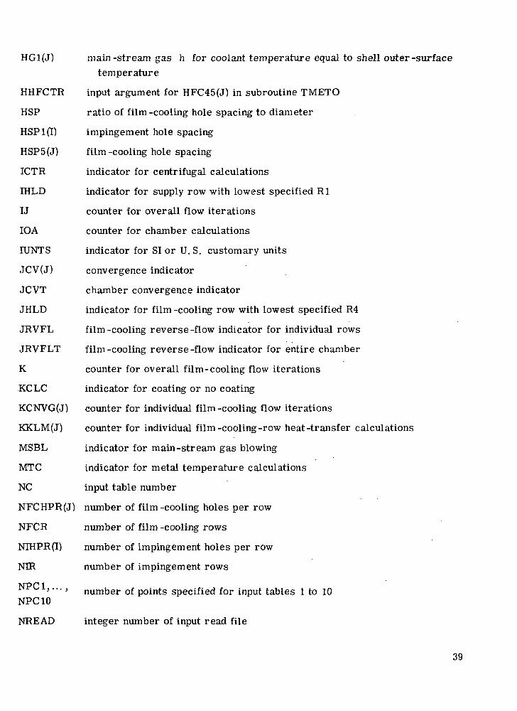
HG1(J) main-stream gas h for coolant temperature equal to shell outer-surfacetemperature
HHFCTR input argument for HFC45(J) in subroutine TMETO
HSP ratio of film-cooling hole spacing to diameter
HSPlfO impingement hole spacing
HSP5(J) film-cooling hole spacing
ICTR indicator for centrifugal calculations
IHLD indicator for supply row with lowest specified Rl
IJ counter for overall flow iterations
IOA counter for chamber calculations
IUNTS indicator for SI or U. S. customary units
JCV(J) convergence indicator
JCVT chamber convergence indicator
JHLD indicator for film -cooling row with lowest specified R4
JRVFL film-cooling reverse-flow indicator for individual rows
JRVFLT film-cooling reverse-flow indicator for entire chamber
K counter for overall film-cooling flow iterations
KCLC indicator for coating or no coating
KCNVG(J) counter for individual film -cooling flow iterations
KKLM(J) counter for individual film-cooling-row heat-transfer calculations
MSBL indicator for main-stream gas blowing
MTC indicator for metal temperature calculations
NC input table number
NFCHPR(J) number of film-cooling holes per row
NFCR number of film -cooling rows
NIHPR(I) number of impingement holes per row
NIR number of impingement rows
NPC1 '"•' number of points specified for input tables 1 to 10NPC 10
NREAD integer number of input read file
39

NWRITE integer number of output write file
OMG rotative speed
PIT (I) total pressure at station 1
P1THLD temporary storage location for PIT
P1TMIN minimum specified supply pressure
P2(I) static pressure at station 2
P2T(I) total pressure at station 2
P3T total pressure at station 3 (vane calculations)
P3TFK temporary storage for P3T
P3TFCR(J) total pressure in impingement plenum at each film-cooling row
(blade calculations)
P3TIR(I) total pressure in impingement plenum at each impingement row
(blade calculations)
P3TMNN lowest allowable pressure in impingement plenum
P3TMNR total pressure in impingement plenum at minimum specified radius
P3TMXX highest allowable pressure in impingement plenum
P4(J) static pressure at station 4
P4T(J) total pressure at station 4
P45 average static pressure in film-cooling hole
P45CNV relative change in P45
P45HLD next-to-last iterated value of P45
P45N last iterated value of P45
P45T average total pressure in film-cooling hole
P5(J) static pressure at station 5
P5HOLD temporary storage for P5
P5MAX highest specified back pressure for vane calculations
P5T(J) total pressure at station 5
P5TCV(J) relative change in P5T
P5TNEW last iterated value of P5T
P5TOLD next-to-last iterated value of P5T
40

P6(J)
PFCR
PHOLD
PN45(J)
PRN
PTN
PTO
R1(I)
R4(J)
REJ2(I)
REJ5(J)
REYN45
RGAS
R1HLD
R4HLD
RHO2(I)
RHO4(J)
RHO45
RHO5(J)
RMN
R1MN
R4MN
ROV2C(J)
ROVG(J)
ROV2G(J)
ROV2R
ROVRAT(J)
ROV2RT(J)
RTCOR
RTCR(J)
static pressure at station 6
temporary storage location for P3TFCR(J)
temporary storage location for P3TMXX or P3TMNN
static pressure at midpoint of film -cooling hole
Prandtl number
input argument for P4T(J) in subroutine MNEW
input argument for P5T(J) in subroutine MNEW
radial distance at station 1
radial distance at station 4
Reynolds number at station 2
Reynolds number at station 5
Reynolds number at midpoint of film -cooling hole
gas constant
temporary storage location for R1(I)
temporary storage location for R4(J)
density at station 2
density at station 4
density at midpoint of film -cooling hole
density at station 5
lowest specified R1(I) or R4(J)
lowest specified R1(I)
lowest specified R4(J)
pV2 of coolant at station 5
pV of main -stream gas
pV2 of main -stream gas
input argument for ROV2RT(J) in subroutine SPLINE
(pV) /(pVL«* &
(pV2) /(pV2LL &output argument for RTCR(J) in subroutine SPLINE
correction factor for CDFC(J)
41

T2(I) static temperature at station 2
T4(J) static temperature at station 4
T45 average static temperature between stations 4 and 5
T5(J) static temperature at station 5
TAU(J) shell metal thickness
T AUC (J) shell coating thickness
TAUI(I) impingement insert thickness
TC input argument for TT in subroutine TMETO
TC2(I) coolant interface temperature (boundary 2)
T2CNVG relative change for T2(I)
T5CNVG relative change for T5(J)
TD temporary storage for T4(J) or T4T(J)
T2D input argument for T2(I) in subroutine AIRPRP
T5D input argument for T5(J) in subroutine AIRPRP
TERM f l . O - [P2(I)]/P2T(I)}(y~1)/y or |l. 0 - [P5(I)]/P5T(I)}(y"1)/y
TG input argument for TMSG(J) in subroutine TMETO
T2HLD temporary storage location for T2(I)
T5HLD temporary storage for T5(J)
TITLE title of calculations
TMI(J) inner -wall temperature
TMO(J) outer -wall temperature
TMSG(J) main -stream gas temperature
TN output argument for T4(J) in subroutine MNEW
TO input argument for T4(J) in subroutine MNEW
TT coolant total supply temperature
T2T(I) total temperature at station 2
T4T(J) total temperature at station 4
T5T(J) total temperature at station 5
T3TAV average coolant total temperature at station 3
T4TAV average coolant total temperature at station 4
42

TTN input argument for T4T(J) in subroutine MNEW
TTO input argument for T5T(J) in subroutine MNEW
T5TFTR relative change in T5T(J)
T5TOLD(J) next-to-last iterated value of T5T(J)
TW2(J) wall interface temperature
V2(I) velocity at station 2
V4(J) velocity at station 4
V45 average velocity in film-cooling row
V5(J) velocity at station 5
WFCR input argument for WOUT(J) in subroutine TMETO
WIMP (I) coolant inflow
WIMPT total coolant inflow
WOUT(J) coolant outflow
WOUTT total coolant outflow
XBETA input argument for BETA(J) in subroutine SPLINE
XCDI average impingement discharge coefficient
XDI average impingement hole diameter
XETA(J) overall effectiveness
XHD(J) impingement heat-transfer coefficient
XHH(J) heat-transfer coefficient in film-cooling holes
XHSP1 average impingement hole spacing
XILOD ratio of impingement distance to impingement hole diameter
XIMP(I) impingement distance
XKA coolant thermal conductivity
XKT film-cooling total-pressure loss coefficient
XKTD output argument for curve 6 in SPLINE subroutine
XLC input argument for XLFCC(J) in subroutine TMETO
XLFC(J) length of film-cooling hole (metal only)
XLFCC(J) length of film-cooling hole (coating only)
XLFCPC(J) length of film -cooling hole (metal plus coating)
43

XLM
XLODFC(J)
XLODIOO
XLODXX(J)
XM2(I)
XM4(J)
XM5(J)
XMD
XMK1(24),...XMK10(24)
XMNEW
XMOLD
XMU
XRHO2
XT4TAV
XV2
XXI,...,XX10
XXAKCT(J)
XXAKM(J)
XXIMP
XXKT(J)
YY1,...,YY10
ZFC
input argument for XLFC(J) in subroutine TMETO
film-cooling hole length-diameter ratio (metal only)
impingement hole length-diameter ratio
film-cooling hole length-diameter ratio (metal plus coating)
Mach number at station 2
Mach number at station 4
Mach number at station 5
temporary storage location for XM2(I) or XM5(J)
calculated values of curve slopes M, for tables 1 to 10
output argument for subroutine MNEW
input argument for XM5(J) in subroutine MNEW
coolant viscosity
average density at station 2
average total temperature at station 4
average velocity at station 2
x-coordinates for input tables 1 to 10
coating thermal conductivity
metal thermal conductivity
average impingement distance
total-pressure loss coefficient
y-coordinates for input tables 1 to 10
input argument for XLODFC(J) in subroutine TMETO
Al
A2
AKCT
Subroutine TMETO
parameter defined by eq. (C5)
parameter defined by eq. (C6)
coating thermal conductivity
44

AKM
AL1
AL2
AREAR
BETA
BETA2
C2,...,C6
CMAT(24,25)
CN(24)
COEF
DA
DA2
DELHG
DEN
ETA
FACVA
HC
HD
HH
HH2
HM
HM2
KLM
REH
RENA
ROOT
ROOT2
metal thermal conductivity
parameter defined by eq. (C30)
parameter defined by eq. (C31)
area reduction ratio
parameter defined by eq. (C22)
parameter defined by eq. (C23)
constants obtained by solving eq. (C45)
general problem matrix to be solved by subroutine XMTSOL
solution vector obtained from subroutine XMTSOL
coefficient (temporary storage location)
parameter defined by eq. (C20)
parameter defined by eq. (C21)
HO - HI
denominator of eqs. (CIS) and (C16)
overall effectiveness, defined by eqs. (B33) or (B34)
arrival velocity factor
HD corrected for presence of film -cooling holes
coolant impingement-heat-transfer coefficient obtained from Gardon-Cobonpue correlation (eq. (Bll), ref. 8)
average convective-heat-transfer coefficient in film-cooling hole(metal only, eq. (B13))
average convective-heat-transfer coefficient in film-cooling hole(coating only, eq. (B14))
internal volumetric-heat-transfer coefficient (metal only)
internal volumetric-heat-transfer coefficient (coating only)
counter for number of wall temperature calculation iterations
Reynolds number in film -cooling hole
impingement Reynolds number based on "arrival" velocity
45

TCA average coolant temperature in film-cooling hole (metal only)
TCAO overall average coolant temperature
TCCAV average coolant temperature in film-cooling hole (coating only)
TCIF coolant temperature at interface plane
TCIN coolant temperature at inlet of film-cooling hole
TCO coolant temperature at outlet of film-cooling hole
TCTAV coating average temperature
TDIF temperature difference, TG - TC/
TFILM film temperature, (TWI + TC)/2
TNEW last iterated value of TWO
TOLD next-to-last iterated value of TWO
TR temperature ratio
TWAV average wall temperature (metal only)
TWI wall inner temperature
TWIF wall interface temperature
TWO wall outer temperature
TWOCVG relative change in TWO
U parameter defined by eq. (C17)
XLTOT total length of film-cooling hole (metal and coating)
Subroutine MNEW
CNVCR relative tolerance for Mach number iteration
DNM denominator in expression for iterated Mach number
I counter for Mach number convergence iteration
POWN
POWO
XMFCN
XMFCO
(y + l)/[2(y - 1)] evaluated at last value of y
(y + l)/[2(y - 1)] evaluated at next -to -last value of y
1. 0 + [(y - 1)/2]M2 evaluated at last value of M
1. 0 + [(y - 1)/2]M2 evaluated at next -to-last value of M
46

XMHLD temporary storage location for XMN
XMN Mach number
XMNEW final iterated value of XMN
XNUM numerator in expression for iterated Mach number
Subroutine PRBMTX
ANGROT coordinate system rotation angle
CAN cos (ANGROT)
F(24) specified points that describe curve in unrotated coordinate system
FR(24) generated points that describe curve in rotated coordinate system
L(24) lengths of intervals between inputted F(24) in unrotated coordinate system
LR(24) lengths of intervals between generated FR(24) in rotated coordinate system
MAT(24,25) matrix of function second derivatives at specified XK locations
N number of intervals generated by XK values of FR (NP1 - 1)
NP1 number of points that describe a curve, N + 1
NP2 N + 2
OPT indicator for rotated coordinate system
SAN sin (ANGROT)
SOL(24) solution vector of problem matrix MAT (24,25)
XK(24) inputted x-values corresponding to inputted points F(24) in unrotatedcoordinate system
XKR(24) generated x-values for a rotated coordinate system
XPFST slope of first interval in unrotated coordinate system
YPFSTR slope of first interval in rotated coordinate system
YPLST slope of last interval in unrotated coordinate system
YPLSTR slope of last interval in rotated coordinate system
47

Subroutine SPLINE
ANGENV
ANGROT
CAN
CANT
GRIT
DELXR
FK
FKM1
FR(24)
IND
LK
MK
MKM1
N
NC
NM1
OPT
SAN
SANI
TERM4
X
XKR(24)
XR
XX
XXM
Y
inverse of coordinate system rotation angle (-ANGROT)
coordinate system rotation angle
cos (ANGROT)
cos (ANGINV)
relative accuracy of iterated y -value for rotated coordinate system
(XX - XXM)/10
value of specified function at first point to right of desired x-location
value of specified function at first point to left of desired x-location
specified y -values of table in rotated coordinate system
indicator for determining whether desired x-value is outside inputtedrange of x
length of interval
value of function second derivative on right side of interval
value of function second derivative on left side of interval
number of intervals that describe a curve
input table number
N - 1
indicator for rotated or unrotated coordinate system
sin (ANGROT)
sin (ANGINV)
terms whose sum rsiequal to spline -fitted value of y
x-location in unrotated coordinate system
specified table x-locations in rotated coordinate system
x-location in rotated coordinate system
specified x-value on right side of interval
specified x-value on left side of interval
spline -fitted value at specified x in unrotated coordinate system
48

Subroutine XMTXSL
DET matrix determinant
DIV value of row pivot element
FCT(24) factor used to reduce elements in pivot column to zero
ISNGL factor for indicating singular matrix
MAT(24,49) overall matrix obtained by adding problem matrix and identity matrix
NC number of columns
NLST NC + NR
NM NR - 1
NN NC + 1
NR number of rows (order of matrix)
NSW number of switches needed to make pivot element the largest element
SOL (24) solution vector
49

APPENDIX F
PROGRAM LISTING
MAIN PR06RAM
DIMENSION TITLE(16IDIMENSION NIHPRI25),R1(25I ,DII25».T»UI<25J,HSP1<25),XIMP(25»,PIT<?*5>DIMENSION NFCHPRI50l,Rtt50),DFC(SO»,»S«SOI,T«Ut5D»,HSP5f SiJI.HFUMfS
*tn,HFC<»5t50»,at.PHM50J ,BET»I50> ,H60t50> ,HG1 t50> ,T*S6t50t ,»b< 50 J ,RO«V6(50>,BO¥26<50»,T»UCI50I.TU2I50I,TC2I50»DIMENSION AIMPf25I,XLODIt25»,P3TIRf25l,XM2l25>,V2f2Sl,T2C?5»,T2T(2
• 5 J.P2C25I ,P?T»25I,COI C25 I ,RH02« 25 J ,»E J2 J25I ,UIHP( ?5IDIMENSION AOUTI50I .XLFC {50 I .XUODFC f 50 I ,P 3TFCR (53 > , JCtf e 531 .KCNVGC50
*) ,XM5«50».WS«50) .T5(50l,I5TI50»,P5f50l,P5TlSO»,T5TOLO<50l,COFCf5D)*.XX»(TC50»,RH05(50> ,ROVR«Tf SO) ,ROIf 2C f 501 ,RO»?PT ( 53 I ,RCJ5 1 51 1 , XL FCC t*SOI ,XLFCPC(SO>,XLOOXX(50I,RTCR(50)DIMENSION T«(50),TUT«5DI ,Ptf53) ,P«T(50I,V4(50I,RNI|5(50),IHII50>,TH
*0<50J,XET*»5D>,XM»150I,HOUTI 50 1 1 »5TCV 150 I ,RHO«K 50 »DIMENSION XHD(SO»,XHH(SO>,XXAKM(50t,KKLMC50) ,XX»KCT(50>DIMENSION X X ] f 2 « > . X X 2 ( 2 * l , X X 3 « 2 ' « > » X X M (2» I .XX5 C24 > ,XX6 (24 I , XX 7 (20 I,
» X X 8 f 2 i 4 > , X X 9 ( 2 4 > f X X 1 0 i ? < »DIMENSION t Y U 2 1 ) , Y Y 2 f 2 1 » . Y Y 3 ( 2 1 l , Y Y m 2 1 l , Y Y 5 t 2 1 > . Y Y 6 ( 2 i ) » , » Y 7 ( ? 1 ) ,
* Y Y 8 ( ? 1 ) , Y Y 9 f 2 « ( ) . Y Y 1 0 ( ? ' l lDIMENSION X H K l ( 2 < l > , X M K 2 C 2 < ) > , X « K 3 C 2 < » . X M > « i r 2 I l > , X * K 5 ( 2 ' t > . X 4 ' < S < 2 ' l l , X «
* K 7 ( 2 < D , X M K 8 ( 2 i | > t X H K 9 ( 2 < l ) , X M K I 3 ( 2 M )
CCMMON NPC1 ,NPC2 ,MPC3 tNPCM , SNSR 1 , «N6R2, « NGR3 , ANSH 1 ,XX1,XX?,XX3,XXM*,YYl,YY2,YY3,YYt,XMXl,XMK2,XMK3,XMKt,NRE:ADtNWRITE
NAMELIST/OATT/1UNTS,ICTR,MTC,MSBL,KCLC,OMG,RG«S,*NIR,NIHPR.Rl,OI,T»UI,HSPlr,XIHP,PlT,TTt
*NFCP,NFCHPR,Rl»,OFC,A5,TAU,T»UC,HSP5,HFC'4 ,HFC15, AL PHA ,3 E T » ,HGO ,HG 1 ,*TMS6,Pb,RO¥G,ROV2G
NRE»D=5
^READ{NREAD,5010) ITITLEtI)»I=liI6lWRITE(NURITE,6010) (TITLEII! ,1=1,1
ANGR1-0.READ(NREAO,SO?0)N»CIIFCNPC1 .LT. 3IGOTO 130RFAD(NRE A 0,5033) {XXIII J ,Irl,NPCI>READ(NREAO,5030)fYYHI),I-l ,NPCI)
DO 10 I-1.NPC113 UPI1E<NURITt, 6030 > <XX1 (U.YY1UU
CALL PR8HTX<NPC1,XX»,YY1,ANGR1,X1K1
RE«DCKRE»D,«iD20)NPC2IFCNPC2 .LT. 3I50TO 1
50
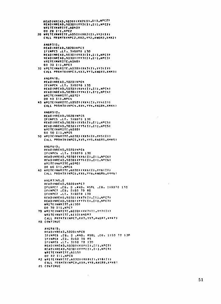
READ < NRE AO, 5030 1 t Y Y 2 < l 1.1=1, NPC?>UR1TECNURITC, 60401DO 20 I=l.NPCZ
?0 URITEfNURITE.60SOI<XX?( I> ,YY2( IMCALL P R B N T X I N P C Z , X X Z , Y Y 2 . A N G R ? , X « K 2 I
AN6R3=0.Rr*0(NREAD,502D)NPC3IFINPC3 .LT. 3I60TO 130READ ( NREA0.5030 M XX3( 1 ». 1=1, NPC3»READCNREAO, 50301 (YY3C I >,!=!, NPC3)WRITECNURITE, 6060100 30 1 = 1 ,NPC3
30 UPITEINWRITE,6030I ( XX 3 ( 1 1 , YY3( 1 1 1CALL PRBHTXINPC3,XX3,YY3.AN6R3,X*K3I
ANGR<)=0.REAOINREAD,502D)NPC4IFINPCH .LT. 3IBOTO 130RE*D(NRE»D,SD3a» 1XX1« I),I-1,NPC<»IRFAO(NRE«D,S030l(YYi|( I>,I-ltNPC4>URITE(NURITE,6070>00 40 1=1 ,NPCM
40 yPITE(NURITE.60SOICALL
*NGR5-0.REAO(NREAD,SO?0)NPCSIFtNPCS .LT. 3>50TO 130REAO(NREAO,S030) (XXS(I),I=1,N<>C5IREADfHRE* 0,50301 (Tr5«ll,I-l,NPC5)URITE(N«91TE,6080)DO 50 1=1 ,NPC5
50 UPITF(NURITE,6030(I (XXS(I),VY5(I)tCALL PR3HTXCNPC5,XX5tYr5,«N6R5,XMK5)
ANGR6-0.R F A O ( N R E A D . 5 0 2 0 ) N P C 6IF(NPC6 .LT. 3 I S O T O 130READ INREAD, 50301 ( X X 6 ( II .I=1.NPC6I
URlTEINUftITE.6090)00 60 1=1 .NPC6
60 yRITF(NURITE:,6030) IXX6(II ,YY6( II »CALL PR3MTX(NPC6,«X6tVY6,ANSR6.X1K6)
RFAO(NREAO,50?0)NCC7iriNPCT .EO. 0 .AND. MSPL .EO. I1G O T OIF(NPC7 .EO. 0)50 TO 80IF<NPC7 .LT. 3 ) B O T O 130REAOINRE A 0,5030) IXX7«I I , I = 1,NPC7)READ (NRE A 0,5030) (YY7( I ) , I = 1,NPC7)WRITE ( N W R I T F , 6100)00 70 I=1,NPC7
70 M R l T E ( N H R I T E , 6 0 3 0 ) ( X X 7 ( T ) , Y Y 7 t n )UR1TEINU!« ITE,6110)ANGR7CALL P R ? H T X ( N P C 7 , X X 7 , Y Y 7 , A N S R 7 , X ^ K 7 )
80 CONTINUE
REAO(NREAD,5020)NPC8IF(NPC8 .EQ. 0 .AND. KSBL .EO. 1)50 TO 1 3PIF(NPCB .EQ. 0>GO TO 65IFINPTB .LT. 3)50 TO 130READ(NREAD,S030I(XXP(I> ,1=1 ,NPCS)RFAO(NREAO,5030) CYY»IU,I = 1,NPC?»URI1E<NURITF,61I5)OC 8? I=1,NPC8
R2 WPlTE(NWRITE,fc030»(XX8tI),YY8(D)CALL PR9MTX(NPC8,XXS,YY8,»NGRB,X1K81
85 CONTINUE
51

AN6R9-0.READCNREAD.5020INPC9IFINPC9 .EQ. 0 .*NO. HTC -EO. 1ISOTO 130IFINPC9 .EQ. 0)60 TO 100IFINPC9 .LT. 3IGOTO 130RCADINREAD,S03DMXX9II>.Irl,NPC9>RCAO(NREAD,5030MVV9II) t I = l,NPC9>WRITE(NWRITE, 6120100 90 1-1.NPC9
90 HRIIE«NWmTE.6030HXX9fII,YY9(IMGILL PRBMTXCNPC9,XX9,YY9,AN6R9,X*K9>
100 CONTINUE
AM6R10=0.READ«NREAD,50?0)NPC10IFINPC10 .EO. 0 ;«NO. HTC .EO. 1 .AND. KCLC .EQ. IIEOTO 130IFCNPC10 .EO. 0)60 TO 120IFINPC10 .LT. 3I60TO 130READ I NRE A 0,5030) (XX10 (I) ,Ir] ,NPC1 0)R E A D I N R E AD, 5030 > t V Y 1 0 t l ) , l r l . N P C 1 0 >W R l T E t N W R I T E , 61301DC 110 I=1,NPC10
110 U R I T E ( N U R I T E , 6 0 3 0 t C X X I O ( I > , Y V i a ( l »CALL PRBMTX(NPC10,XX10,YY10,AN6Ria , i rMKlD)
120 CONTINUEGO TO 140
130 URITEtNMRITE,6mO)GO TO 2000
1X0 CONTINUE
tcc
ccccccccc
1 HI fKUBKHn 1 I LK« ! HI"H «Kt LUKHltJ OU 1 IU HLLBIlVt » \,\. UK » I. 1 I i irtUiritU
BY flBHT CONVERGENCE FACTORS (DENOTED BY CFXXXI. EXCEPT FOR CFFLOW,THESE FACTORS ARE DEFINED AS ABSHOIO VALUE-NEW VALUE)/«NEM VALUE! 1.
CFT2 -CFT5 -CFT5T -CFP5T -CFP45 -CFMCH -CFFLOW-
CFTWO -
CONVERGENCECONVERGENCECONVERGENCECONVERGENCECONVERGENCECONVERGENCECONVERGENCE(DEFINED ASCONVERGENCE
FACTORFACTORFACTORFACTORFACTORFACTORFACTOR
FORFORFORFORFORFORFOR
STATIC TEMP.STATIC TEMP.TOTAL TEMP.T3TAL PRESS.STATIC PRESS>UCH NUMBERTOTAL INFLOW
AT STATION 2AT STATION 5AT STATION 5
AT STATION 5. BETWEEN STATIONS « AND 5BETWEEN STATIONS 4 AND SAND OUTFLOW
ABS(«INFLOW-OUTFLOW)/(SMALLER OF THE TWO FLOWS))FACTOR FOR 1ETAL OUTER WALL TEMP.
CFTSr.ODlCFT5T:.D3IC F P S T r . O O l
CFMCH:. 031CFFLOW:. aoiCFTWO:. 331
cC ----- SCT DEFAULT VALUESC
IUNTS-0I C T R r nM T C 3 DMS3LrOK fLC-eRGAS:53.35I OA :.0DO It? 1=1,50H F C 1 ( I ) : i . O
115 H F C M 5 U > - 1 . C I150 C O N T I N U E
I O A T I O A « 1READ(NREAD,DATT,ENDT2000>WRITE (NWRITE,6)SOriOAIFCIUNTS .EO. 0»GO TO ItO
GO TO 170
52

160 U R ] T E ( N U R 1 T E , 6 1 7 0 )170 C O N T I N U E
iFduim .EO. o isoro leaWRITEINWRITE,61BOJRG»S60 TO 190
180 WRITEIN«RITE,6190IRG»S190 CONTINUt
IFIICTR .CO. OIOHSrO.0IFIICTR .EO. 1160 TO 20060 TO 210
200 «R1TEINWRITE,6200)OM6210 CONTINUE
IFIMTC .EO. 1 .»ND. KCIC .£0. 1160 TO 2?060 TO 230
2 2 0 U P I T E I N U R I T E . 6 2 I O I230 C O N T I N U E
I F C H T C .EO. O I S O T O 2 4 060 TO 2SO
240 HRITEINWRITE, 62201250 CONTINUE
IFIMSBL .EO. 0160 TO 26060 TO 270
260 HPITEfNURITE, 62301270 CONTINUE
IFdUNTS .EO. 1)60 TO 2SOURITEINURITE.6210INIR60 TO 290
2*0 URITECNURITf ,6250>NIR290 CONTINUE
Cc ----- CONVERT INPUT UNITS I EN6LISH OR SI) TO WORKING EN6LISH UNITSC
IFdUNTS .EO. O I T T r T T « D60.I F d U N T S .EO. 1 )TT = TT»9. /5 .I F I I U N T S .EO. 0 ) R 6 « S = R 6 A S * 3 ? . 1 7 «I F I I U N T S .EO. 11BS»S:RG*S«5.9BO
DO 310 I r l . N I RX L O C K I I - T A U I ( I ) / O I ( I 1« R I T E « N W R I T E , 6 2 6 0 I I , M I H P R < I ) , O H I I i T » U I ( I I . X L O O I (I I ,HSPI 111 , 'XIHPd
* l , R l d ) , P I T ( I )I F C I C T R .EO. 0 ) R 1 ( I > : 0 .IFdUNTS .EO. 0160 TO 300R 1 I I ) = R I ID/25. 1OKI l -DIdI /25.1
H S P l l I l = H S P i ' d > / 2 S . «X i n P I I l r X I M P d l / 2 5 . HPlTdl = PlTdKl ."»50377
300 C O N T I N U E
I ) *3. 1* 1 6 » < O T II » /2 . 0 )*»2/l »» .01d)-DId)/12.T « U I d l r T K U I d ) / I 2 .
HSP1 ( I l rHSPId) / ! ? .I F C I C T R .EO. l l R l d ) - R l d l / I 2 .
310 C O N T I N U EIFI IUNTS .EO. 1160 TO 320U R I T E I N V R I T F . 6 2 7 0 I N F C RGO TO 330
320 V R I T E ( N U I } I T E , 6 2 8 0 I N F C R330 C O N T I N U E
00 370 i r l . N F C RIFIKCLC .EO. 0 > T A U C ( I ) = D .IFIKCLC .EO. I .•MO. TOUCH! .EO. 0.0)60 TO 340GO TO 350
340 URITEINyRITE.6290)60 TO 1000
J50 CONTINUE1/57. 29578)
53

II ) /57. 29578 )X L F C C m r C T A U C I I I » /SI N ( ALPHA 1 1 IV57.29578 »X L O D F C I I I = X L F C C I » / D F C < I IX L O D X X t n r X L F C P C < n / D F C U >IF(HSBL .TO. 0 )ROVSCI> :0 .I F C M S S L .EO. 0 )ROV2Gd i rO .WRITE(NWRITE ,630DI I .NFCHPRt I I ,DFCf I ) ,TAUd) ,TAUCd » . X L O D X X d ) ,HSP5
*( I> .ALPHA (I) .8E.TAII) , ROVG < I > , UOV? G ( I > ,R4ll) ,P6II>IF( ICTR ,E3. O IR4 I I 1 = 0.TTdUNTS .EO. D 1 S O TO 360RMC I t -H<t i II/ifB.'JDFC (I > - D F C C D/25.S1» 5 C I ) - A 5 ( I ) / <T«U( I ) rT»U( I I /25 . t
X lFC( I ) r xLFC«IJ /25 . i )XLFCPCdl^XLFCPCU l /25.<<X L F C C ( I I : X L F C C C I > / 2 5 . MHSP5( I ) rHSP5( I ) /25 .1HGO(I ) :KSO(I ) *0 .17fc228HP1 f I>rHSKI)*D. 176228
ROVG(I>rROVG(I)/«l.8821276ROV2G(I>:ROV2B(I)Vl.<te81639
360 CONTINUEP t ( I ) r P 6 ( I ) * l M « l .P ? ( I I = P & ( I IAOUT( I l rFLO»T(NFCHPRtHJ*3 .1 'H6* tOFC( I I /2 .Qt * *2 /11<( .
DFC(1»=DFC(1> /12 .T«U t T ) = T A U I T I / 1 ? .T « U C ( I > r T A U C ( I ) / 1 2 .X I F C ( T > - X L F C ( I I / I 7 .X L F C P C « n = X L F C P C ( I )XLFCC(IlrXLFCC(TI/12.HfP5m=HSP5U»/12.IFdCTR ,EO. ]IR
370 CONTINUEIFdCTR ,EQ. 1150 TO «20
CC ----- (THf FOLLOKING CALCULATIONS ARE FOR NO CENTRIFUGAL EFFECTSIC ----- FIND P1TNIN AND P5MAX (NINIHUX SUPPLY PRESSURE AND MAXINU1 FILM COOLINSC BACK PRESSUPE)-6ET INITIAL 6UESS FOR PLENUM TOTAL PRESSURE CP3TJC
DP 380 I-I.NIRPITHLOrPlTdlIFd .EO. JIPtTMI»(rPlTHLDIF(P1THLO .LT. P1THIN I PlTIINrPl THLD
380 CONTINUE
00 390 Irl,NFCHPfHOLD=P5«I>IFd .ED. »>P5NAXrP5HOLOIFIP5HOLD .6T. P5f AX» P5KAX-P5HOLD
390 CONTINUECC CHECK THAT P1TMIN IS GREATER THAN P5MAXC
IFCP1TNIN ,LE. PSHAXIGO TO «03GO TO 410
400 WRITECNyRITE.6310160 TO 1000
410 CONTINUEP3TMXX=rPlTH7N
P3TTCP3TNXX « PJT1NN1/2.60 TO 500
420 CONTINUECC ----- (THE FOLLOWING CALCULATIONS ARE FOR CENTRIFUGAL EFFECTS!C ----- FIND R1HN AND R4«M ILOHEST RADIUS FOR SUPPLY HOLES »NO FC HOLES! AS MELL
54

C AS THEIR CORRESPONDING INDEXES IIHLO AND JHLOI, DESIGNATES THE LOWESTC RADIUS Bt RUN. CALCULATE THE HI6HEST AND LOUEST ALLOWABLE PRESSURES INC THE PLENUM AT RNN WHICH PRECLUDE REVERSE FLOW IP3THXX AND P3THNNI. GET ANC INITIAL PLENUM PRESSURE PROFILE IASSUNE T EQUALS TT1.C
DO 430 1=1, NIRR1HLO=RICII1FII .EO. 1»RINN=<»IHLOIFfI .EO. 1»IHLD=IIFCRIHLD .LT. H1NNIR1 HN=R1 HLOIFIR1HLO .LT. RMNIIHLO = I
030 CONTINUE
DO 119 J-1,NFCRR<tHLOrR»( JlIFIJ ,EO. 1 »R*NN=R»HLDIFIJ .EO. 1IJHLD-JIF{R«lHLD .LT. R»NN IR1MNrR»HLDIFCR4HLD .LT. R4HWIJHLD=J
DUO CONTINUEIFCR4HN .LT. RUN I «HN = R«IMNP3THXX=P1T<IHLD>
DO ISO Irl, NIRPHOLO-PJ Til l»?.7IS3**»OMS*OM6»f R*N*RNN-RlfI»*RHI I J/(2.«R5»S*TT)IFCPHOLD .LT. P3Tf XX» P3TNXX=PHOLO
*50 CONTINUE
00 160 JM.NFCRPHOLDrP6IJ I *2 .7185** (OMB*OMS*(R1« l *RHN-R i4«J I *Ra(JH/C? . *RB«S*TT) )IFCPHOL3 .ST. P3T>«NNIP3TNNN = PHOLD
460 CONTINUEIF IPJTMXX .LT. P 3 T H N N J G O TO <>90P?TMNR:»P3TMXX*P3THNN) /2 .
00 170 1=1, NIRP3TIRCH =P3TMNR*2.7183»*«ONB»3HS*(R1CI I«R1( I ) -R1N»RHN J / (2 . *R6«S*TT
*) )<»70
DO M80 J-l.NFCRPKTFCR(J):P3TMNR*?.7183»*ro>«G*!)1S*»R'»<JI *R"» f J I -»NN*RHN >/ < ? ,*R6ftS*T
*T)»M8D CONTINUE
60 TO 530H90 WRITE(NH!»ITE.63ia>
60 TO 1000500 CONTINUE
CC ----- THE FLOd IS SOLI/ED »S FOLLOWS - • PRESSURE OR PRESSURE DISTRIBUTIONC (P3T OR P3TIRUI t P3TFCRIJJ FOR NO CENTRIFUGAL AND CENTRIFUGAL EFFECTS,C RESPECTIVELY) IS «SSUHED IN THE >LENUN AND THE INFLOW AND OUTFLOW AREC CALCULATED FOR TH«T PRESSURE OR PRESSURE DISTRIBUTION. THE ASSUMEDC PRESSURE OR PRESSURE DISTRIBUTION IS THEN ADJUSTED TO EOUSLIZE' THEC INFLOW «MD OUTFLOWCC ----- IJ IS THE COUNTER FOR THE OVERALL FLOW ITERATIONSC
IJ=0510 CONTINUE
IJ=IJ*1CC ----- ASSUME ORIFICE TOTAL PRESSURE EOJALS SU°PLr TOT«L PRESSURE (PC1U)»C AND THE ORIFICE STATIC PRESSURE i3UALS THE »LENUH TOTAL PRESSUREC <P3T OR P3TIRI1I)C
DO 560 1=1, NIRT F C J C T R .FO. 0 ) P 3 T I P ( I »rpJTP ? T t I I : P I T ( I IT 2 T ( 1 ) : T T
55

DO 550 Ilrl.15P? t l ) = P 3 T I R f I JIF11I .TO. l ) T 2 f I ) r 0 . 9 5 r ) * T 2 T ( I I
CALL AIRPRPCT2D.IUNTS,*G.GM1,GM1DG,GP1,S1>ID2,GDG*1.6M1DZ,XHU,PRN.XKA,CP)
T F R M ; C I . 3 - : « P 2 I I » / t > 2 T » I I > * * 6 M I D B »I F 1 T C R * .LT. O.t» T E R M =0.0V2< I > - S O U K f 2 . 3 * 6 * R 6 « S * T 2 T ( I ) / 6 M l » * T E R M >X K 2 ( I I = V 2 I I > / S 9 R T C G » R 6 A S « T 2 T ( I ) * ( P 2 t I ) / P 2 T ( I M * * S M 1 D G II F f X M ? C I ) .GE. 1.1JGO TO 523T ? t I i r T 2 T i n / « 1 . 0 * 6 M 1 0 2 » X » 1 2 f I )60 TO 533
5?D X M 2 I H - 1 . D
V 2 ( I ) r s O P T ( G * R 6 « S * T ? ( 1 1 )P 2 ( I ) r o ? T f I ) / G P 1 D ? * * 6 D 6 M 1
530 C O N T I N U EX H D T X M 2 C I I
CALL Sf>LIME(NC,NPC5,XX5,tY5.XHD,»N5I?5.XHK5,CDD)
COI (I)=CDORN02CT>rP2ITI/(RG»S*T?(I>>T?CNVG:»BS«T2HLD-T2(IH/T?CI»IFfT2CNtf6 .LE. CFT2>SO TO 5SOIFCII .EQ. 15)50 TO 540GO TO 550
510 WRITECNWRITE, 632DJI550 CONTINUE560 Rrj2(I»-RHO?(n»»?<I)*OICI»»CDI<ri/XHU
CC ----- GET «VE3«GE VALUES FOR IMPINGEMENT H C»LCUL« TIOMSC
xxiMp=o.aXDI=0.0XHSP1-0.0XRH02-0.0XCDI=0.0XV2r0.3
00 570 1=1, NIRXXIHP= XXIMP • XI*PU»/rLO*TCNIR)XDI= XDI • DItll/FLOATCNIRIXHSP1-XHSP1 « HSP1 tIJ/FLO*TINlH»XRH02- XRH02 « RH02 H >/FLO»T( HIR >XCDI-XCDI « CDiell/FLOATINIR>
570 XV2= XW2 « V2(II/FLOAT(NIR>CC ----- CALCULATE INFLOW CLBM/HRIC
yiMPT-0.0
00 580 I=I,NIRCOIFC^COICIfUIHP(II-CDIFC*AIMPCII*RH02II1*V?(T»*32.17<*3600.yiMPTrylMPt < UINPCII
580 CONTINUEC
CC ----- CALCULATE VELOCITT OUT THE FILH COOLINB HOLE. ITEBATE FOB P5T.CC ----- K IS THE COUNTER FOR THE OVERALL FILM COOLING FLOW ITEMIIQNSC
DO 760 KM, 15
00 590 I=I,NFCR
56

XM5<1>:3.590 CONTINUE
DO 670 I-l.NFCRIFdCTR .EO. 0 » P 3 T F C R d ) = P 3 TIF(JCVd) .EO. 1ISO TO 670IFIK .EO. 1IT5TI I>=TT«CTHS6d>» '»60 . -TT l *O .SOIFCHTC .EO. OIT5TI I I2TTT5TOLOdl=T5T( I )
DO 650 11=1,15IFIII .EO. l lT5d»=0.95»T5Td>
CALL AIRPRPITSD.IUNTS,«6,SM1,G'11DG,GP1,6P1D2,GDGMI,6MI02,XMU,PRN,XKA,CP>
TSHLD^TSIIIT F ( P 5 T d > .LE. P5f II )P5T( I >rPSdl*I .00100 620 KK-1 ,15
CC KCNWG IS THE COUNTER FOR THE IN3IVI9UAL FILM COOLING ROW FLOW ITERATIONSC
KCNV6U ) :KK
IFIKK .EO. lIPSTd l=P3TFCRdlPSTOLDrPSTdJTrRM:(1.0-(P5(I»/»5T«III**6MlDGJIFJTERH .LT. 0.0)TERH=0.0
(2.D*G*R6AS*T5Tdl/G1I »*TERMII ) / S O R T ( G » i J G A S * T 5 T « I ) « ( P 5 d I /P5T( I» * *SM]3GI
IF IXM5CI ) .6E. 1.31 GO TO 600T M I K T S T 111 / II .0» BM1 D2*XM5 d ) »X15( I 1 IGO TO 610
600 XP5 d jrl.0T 5 ( I > - T 5 T d l / < 1 . 0 » G M l D 2 )
P5II I=P5Td I /GP1D2**60GH1610 CONTINUE
X K O - X ^ S d )
C A L L SPLINE (NC,NPt :& ,xx6 . rY6 .x i3 , IMS R 6 , x n K 6 , X K t D )
X K T r X K T OPST d » : ( P 3 T F C R ( I) « PS d ! * X K T I / ( 1.0 » X K T )P S T N E W r P S T d )
I F ( P 5 T C V ( I ) .LE. C F t > 5 T 1 6 0 TO 6306?0 CONTINUE
W R I T E ( N « R I T F , 6 3 3 0 H630 CONTINUE
R H 0 5 d l r P 5 ( I I / ( R S » S * T 5 d ) lT ^ C N V J : « 3 S « T 5 « L O - T 5 d I l /TS I t II F C T 5 C N 1 / 3 .LE. C F T 5 J S O TO 660IF( II .Id. 151GO TO 610GO TO 650
610 W P I T C < N r f R I T ? : f 6 3 ' » 0 > I&so CONTINUE:663 CONTINUE
X X K T ( I » r X K TP O « ? C n > - " ? H 0 5 ( I ) * l / 5 { I > * V 5 ( I IIFCMS^L .E3. niROV26CI 1=1.0' O V ? R T d ) : ? 1 V ? C d ) * 3 ? . 1714*3603. * 3 6 3 3 . / R O V ? G ( I >IFIMSPL .EO. - 1 ) R O W 2 » T ( I >:0.0
I F C H S 9 L .EO. 0 ) G O TO 665
57

CALL S P L I N E » N C , N » C 7 , X X 7 , Y Y 7 , R O V 2 * , A < I G R 7 , X M i < 7 , r D O : nNC=8CALL S P L I N E « N C , N P : 8 , X X 8 , Y Y 8 , X B E T » , A M G 1 » 8 , X H K < l t ' ? T C 3 ' M
665 CONTINUEI F C M 5 B L .EO. O J C O O O - 1 . 0IFrHSBL .EQ. DlRTCOP=l.nR T C R « H = R T C O RCCFCII|rCDOD*RTCO!»IMflSBL .EO. Q»ROVG(I1=1.0ROVRAT<I)rRH05lII«V5(I)*32.17i|*3SOa./!?OVG(I)TFIKSBL .EQ. 0»ROKR*T(Il:a.O»EJ5«I)rRHO^tI)*W5ri)*DFC«I)»CDtC» I J/.X'IU
670 CONTINUECC CALCULATE TOTAL AMD STATIC PRESSJ?E AMD TEMPERATURE AT THT ENTRANCEC OF THE FILM COOLI16 HOLE.C
oo 7jo T : I , N F C RI F C J C V C O .EO. 1»SO TO 73?I F ( K ,E3. 1 » T " » T H > = T TI F ( M T C .EO. 0 > T H T ( I » r T T
00 7JO IZ=1,15IFIII .TO.IFIII .EQ.IFtll .TO.IFiTI .E3.
)PMT(T )=PST(I 1*1.075
)¥t( II r«5(I 1*9.90IT<I( I ) rT5 (I 1*0.99* P 5 T ( I 1 1 / 2 ,
P U 5 - I P 1 t I 1 * » 5 U 1 > / 2 . 0V P S r C V M I 1 * V 5 ( I I 1 /2 .0T " 4 5 - l T i 4 ( l I « T 5 ( I I 1 /2 .3PtSHLO-PIS
C A L L A I " ? P R P < T 1 5 , I ' J N T S ,
f> H 0 <( 5 - P H S / ( I? & A S * T <4 5 )
.LT. 2530.1I F ( R E Y N ! 4 5 .GE. 2530 . ) F(?FC = 1.122SE -b*!?r Y\ 1 ?»* 1 .D7 s T9I F ( R E Y N 1 5 .GE. M 0 3 0 . > F ^ F C r 0 .395 3/ RE Y « j u b* *0 . ?617D F L P T T F R F C * X L F C P C ^ I > * P H 0 ^ 5 * » ' l 5 * * ^ / C 1 5 F C ^ I ) * ? . ^ ^P 1 T I I I r P S T I I ) + O T L P T
I IA OLD -1.3A ME U - 1 . 0T O r T 5 f I »T T O r T S T t l lT T N - T " | T ( I 1X M O L O r x M S ( I )
C A L L M M E ^ ( C F M C H , P T 3 , 3 T N , * O L ? , » M E r f , T T , T T S . T T M , * l 3 L l , I U M T ! i ,* X « M E W , T N )
.LT. 1 . 3 I G O TO 69 n
.SE. 1 . 3 1 X » « ^ E k i r l .0T O r T M T ( I >
C A L L A 1 ? ? R P ( T
or eon j = i , i aT f . T T H T l I J / C l . O « 3 M I 3 7 1
C A L L A I R ' R P C T
GCWG:A9S(6TST-3AHk/5TSTIFIPCVS .LE. P.0.01)^C TO 69TGAiriTST
fcRO CONTJMJ-
58

X"M ( I lr « 1 N f . WI M < I H I MT!?;T*f I )
C * L L «I»P»P( TO, IUNTS,PJ ,G :M52,GOG'<1,SM102,X«U , P » N , X K A , C B »
P M 5 N : f > < i C J » * P 5 ( l l l / ? . 3
J V . L E . C F 3 < ( S > G O T O 7 2 0IF t I I '-.3. 15 )50 TO 700G C T O 7 1 D
700 W R I T E C J W S I T E ,6 3501 I7 1 0 C O N T I N U E7?D CONTI»JUr
Ir("TC .̂ 3. 0130 TO 730TC-TT-ISD.FCHSPTHSPSC I IFCHOrOFC( I )H5P:FCHSP/FCHDZFC=XLOOFC«IIHnrHGfillHirHGll I >XlLODrxxlMP/XDIH F C T R - N F C M ( T I
XLMrXLFCI I)XLCrXLFCC(I)»05-AOUT(I 1IF(K ,E3. 1 IWOJT (I |r«IMPT/(FLO*TtMFCR» 'WFCO-WOUT ( I »
TC-T«»SS(I »
CALL TMETO«IJ,TC,FCHSP,FCHO,HO,H1 ,X I LCD .XPH02 ,XV2 ,XLM. ,XLC ,*XWSP1,HFCTR,HHFCT^,XC01,D8U,ZFC,WFC'»,»05 ,FCBLR,TG,HSP, IUNTS,«tT»,TCO,TCIM,THI,TaO,KL»,*K!1,HO,HH,CFTyO,KCLC,ftKCT,0»U2,TWIF,TCIF1
T f O U > = T iJOX F T » I T l r E T AXHDIIIIHOXHHI I IXHHX X A K M C I l;»KK
T W 2 ( I ) i T W I FT C 2 « I ) : T C I F
7 3 0 C O N T I N U ECC - - - - - C A L C U L U S O U T F L O W ( L 3 H / H R >C
U OU T T 3 3 .
00 7<IO m .NFCRU O U T t T | r C O F C t I > * A O U T « H * R H 0 5 ( I I » K 5 « I ) * 3 ? . 1 7 1 * 3 6 3 0 .«OUTT-«OUT1 « «OUT (I)
7"»0 CONTINUECc ----- CHECK THAT TST H*$ CONVERSEDc
00 750 I r l . M F C R
59

= » 3 S ( T 5 T t M - T 5 T O L O C I M / T 5 T mI F t T S T F T R .LE. CFT 5T ) JCV ( I I - 1
7<O J C V T r J C V T « JCVU)I F < J C V T .EO. N F C R I G O TO 7°0
760 CONTINUEW R I T E t N U R I T E i & 3 6 i j ) I J
Cc ----- COMPARE HEIGHT FL3US AND ADJUST P>3T TD B A L A N C E THEMC
1 F ( W O ' J T T .ST. WIM^MFLOFCr l W O U T T - W I « * P T ) / W J * ° TIFIWIMPT .ST. yOUTT)FLOFC:(yiMPT-«OUTT) /MOUTTIF<FLOFC .LE. CFFLOW1GO 10 863IF(IJ ,SE. ?5)60 TO 850IFtlCTR .EO. 1)50 TO 790
CC ----- (THESE CALCULATIOMS APE FOP NO CENTPIFUGAl EFFECTS)C
IF(HOUTT .GT. WIM»T J P 3TMXK=P JTIFIWIMPT .GT. »OU1T)PJTMN»i:P3TP3Tr(P3TMXX * P3T1NN1/2.GO TO 51 D
790 CONTINUECC ----- (THESr CALCULATIONS ARE FOR CENTRIFUGAL EFFECTStC
IFtWOUTT .GT. KIMPT >P 3TMXX =P3T MM*IFIUIMPT .GT. MOUTTIP^TKNP 3 T M N P : ( P 3 T H X X + P 3 T M N N J / ? .T M T A V - D .
00 800 JrTUTAVrTHMV + T1T«J)
800 CONTINUET*T«V=T1T*V/FLOAT«NFCR»XTi|TAV:T»TAV-it60.T 3 T » V r l T 4 T A V + T T ) / ? .IF(MTC .£0. OIT3T9V-TT
CC ----- ESTABLISH P3T AT THE IMPINGEMENT AND FILM COOLING ROW R«OI1 ANO CHECKC THAT THE NEtf PRESSURE DISTRIBUTION DOES NOT CAUSE INFLOWC
DO 810 1=1, NIRP 3 T I R ( I > = P 3 T M N R * 2 . 7 1 B 3 * * t O M G * O M S * ( R l (II*R1 (I I -RIM *R«1N ) /( 2 . * R 6 A S * T T
* T » V ) >810 CONTINUE
DO 830 KNT1,10JPVFLTT3P3TFKro .DO 820 J^I.NFCRJRWFL-0P3TFCRJ J I=PJTMNR*? .7183»*<OM5*OM3* (9M(J»*p iH J » - 3 M M * R H M ) / ( ? . * R 6 A S * T
« 3 T A V ) »IF iP3TFCa(J t .LI. PB tJMJRVFL^ lJR«FLTrj»VFLT«JRtfFLIF(JRWFL .EO. 1 »P3THLD = P3TMNR*M.» IPS I J > -P3TFCRJ J> »/P5( J»>IF(JRVFL .EO. 1 .AND. P3THLD .GT. PJTFK I P3TFK TP3THLO
820 CONTINUEIFIJRVFLT .EO. OJSO TO 810IFtJRVFLT .6T. 0 »<>3TNNR=P3TFK1FJP3T«1NR .GT. P3TMXX >P3T1NR:P3T"IXX
830 CONTINUEURITEfNilRITE,63IO>60 TO 1000 ^
840 CONTINUE60 TO 519
850 URITFfNURITE. 6370160 TO 1300
860 CONTINUECC ----- o»T» OUTPUT ----- D*T» OUTPUT ----- 0»T« OUTPUT ----- DATA OUTPUTC
60

WRITE (NURITE, 63801 IJ
IFdUNTS .EO. 1ISO TO 870MRI TEfNVRITE, 63901 UIHPTURITE<NURITE.640ai60 TO 880
870 «IHPT=1IINPT*0. 45359URITE(NUftITE.6410>UIHPTURITE(NVRITE,6«20)
880 CONTINUE
DO 910 1=1. NIRIFIIUNTS .EO. 0160 TO 890PlTIIHPlTCII*1.7BB33E-3P2TIII = PZTm*4.78803E-3P2III=P?eiI*4.78833E-3
T2III=T?III*5./9.«IHPCU:«INPC 11*0.15359GO TO 930
890 CONTINUEPlTfII-PlTIM/l«4.P2TCIl=PZTm/114.
T2TII)=T2T{I1-460.
900 CONTINUEWRIT t ( ^WRITF ,6 i»JOU,F> lT«H . P? ( 1 1 ,XHZJ I > ,T2T { 1 1 , T ? 1 1 1 ,W1 N»( I I ,COII
*II910 CONTINUE
IFIIUNTS .EO. 1150 TO 920WPITE(NURITE,64<)OIUOUTT
60 TO 930920 U O U T T r y O U T T * 0 . » 5 3 5 9
URITE(NKRITE.6«70I930 CONTINUE
00 960 Irl.NFCRIFCMTC .EO. OITCZCII-TT-IJ&O.IFIIUNTS .EO. 0160 TO 910
TX(I )rTHIP5T JIlrP5T(Il*i».7i8a3E-3
P6(II=PSCIl*«1.7B803E-3T5T ( I I=TST( I I *S. /9 .T5.( Il = T5t II*5./9.TC2 r i ) r « T C 2 < I I • 16d.>*5./9.IFIKCLC .EO. 01TC?t I ) rO.PFCR = P3TFC"? f Il*i».78803E-3UOUT(TI:UOUT(I1*0. 1535960 TO 950
9<tD CONTINUEP M T C 1 ) = P « » T ( I > / l " » q .P f l ( I i rPK I 1/1114.T 1 T J I > : T 1 T ( I 1 - 1 S O .T l d l r T I (1 1-160.P 5 T C 1 | rP5T(II /111.P 5 I I | r P S I I I / t m .
T5T U l rTST f 11-460.T5( I I=T5l l ) -463.IFIKCLC .EO. Q I T C ? ( I I = 0 .PFCRrP3TFCRtI l /111.
9SO CONTINUEUPITe»NH3ITE,6190>I.PFC'»,P1CII,X'1HI I ,T «t I (1) , It (I » , PST (1 ) , °5 ( 1 ) ,
* X M 5 U I , T 5 T I I I , T 5 ( I l , T C 2 ( I l f « O U T C I » , X X K T 111 ,COFC( I I t ' T C R « 11 , R O V R A T «* 1 ) , P O V ? S T ( I ) , K C N V 5 ( I )
61

960 CONTINUEIFIHTC .EO. 0»&0 TO 1 PCDWR1TE(NW»ITE, 61951IFdUNTS .EO. 1)50 TO 970
GO TO 930970 CONTINUE
«RITE(NW»ITE,6500)980 CONTINUE
DO 995 Irl.IFdUNTS .EO. 1>SO TO 9B5
GO TO 9909S5 CONTINUE
HFOd) = HSOdI*S.67«l<l&HE] (I
XHDUI-XHOd J*5.67"»«6*5H )r»5(I>*9?9.0J01T»>SG(I) : (THSS«I>»i»60.)»5. /9.T)*0(I )- ( T H O ( I ) « 160. 1*5. /9.TV2( I I= f TU2( I ) • «60.)*S./9.IFIKCLC .E8. OITW?I I I=D.TCI fIl:(TNI(II * 160.X5./9.X X A K H t I ) r X X « K M I I 1*0.0 17296X X « K C T « I » r X X A K C T « I )«O.OI7?96
9°0 WRITE (Ny (? ITF ,65 IO t I.H60(II .HG1 ( I) ,XHH fl ) ,XHD ( 1 1 ,HF COSt 1 1 , HFC« ( I ) ,* A 5 C I > , T M S 6 ( I ! . T N O ( I > t T V 2 f I ! ,TNIU>,XXAKHt I ) , X X A K CT ( I > ,XET« ( I I ,KKLM*<I)
995 CONTINUE1000 CONTINUE
-RETURN VARIABLES TO ORIGINAL TY°UT UNITS
'3.11159IFdUNTS .EO. O I T T = TT-i»60.IFdUNTS .EO. HTT=TT*5. /9 .IFdUNTS .EO. O I R S A S Z R 6 A S / 3 2 . I 7 1IFdUNTS .EO. 1 J R S A S ^ R G A S / 5 . 9 9 0
DO 1023 1=1,NIRIFdUNTS .EO. 1 > G O TO 1010OTd)-OId)*12.T « U I ( I > - T « U I d > * 1 2 .HSPUI»rHSPHI»*12.
GO TO 13201010 CONTINUE
RId)=RIdI*304.8Did )-DI (1 >*3D1.8
HSP1 «IJ:HSPId»*331.8XIHP< I» rX
1D20 CONTINUE
DCIFdUNTS .EO. 1 I G O TO 1030
HSP5CIirHSP5(I>«12.T A U C I ) = T A U f 11*12.T«UCIII=TAUC(II*I2.R1CI>rR1d)*12.IFIHTC .EO. DrA5(II=ASIII*I44.GO TO 1040
1030 CONTINUE
OFCIIlrDFCdl*30».B
HSP5(I)rHSPS(II*30«.8
62

ROVG<I )=ROVE( I I *<>.882<«276ROV2GII I=ROV26II l« l ,»8816391FIMTC .EO. 0»»5U»= :AS f IM929.030*
1040 CONTINUE
-FORMAT S T A T E M E N T S
5010 FORM«TClb«5l5020 FORKAT(I2I5030 FORM«T<3F10.0I6010 FORMAT! 1H1 ,// ,16A5,// >6020 FORMAT!/, IX, S7H ---------------------------------------------------
* ----- ,/,SX,H3HIN!>UT POINTS FOR COOLANT GA«t*A VERSUS T «*?,/, 12X.1*HX,9X,IHY ,/>
6030 FORHATC5X.2F10.ill6010 FORM ATI /,1X,57H ---------------------------------------------------
» ------ ,/,5X.H7HINPUT POINTS FOR C03LANT VISCOSITY VERSUS T ARE./.1*2X,lHX,9X,lH»,/»
6050 FORMAT«5X,FIO.»,2X, E12.il6060 FORMATf/,lX,5TH ---------------------------------------------------
* ------ ,/,5X,51HIN»UT POINTS FOR COOLANT SPECIFIC HEAT VERSUS T ARE*,/,12X,lHX,9X.lHY,/ »
6070 FORMAT( /,1X ,57H ---------------------------------------------------» ------ ,/,5X,58HIN?UT POINTS FOR COOLANT THERMAL CONDUCTIVITY VERSU*S T APE./,12X,1HX,9X,1HY,/1
60*3 FOR HUT (/.I X.57H ---------------------------------------------------, ------ ,/,5X,<i9HINPUT POINTS FOR IMP. DISCH. COEFF. VERSUS M2 ARE,/*, 12X,1HX,9X,JHY,/)
6 090 FORMAT(/,IX,57H ---------------------------------------------------* ------ ,/,5X,67HlNPUT POINTS FOR FILM COOLING TOT. PRESS. LOSS COEF*F. VERSUS MS ARE,/,12X,1HX,9X,1HY,/)
61 00 F O R M A T ! / , J X , 5 7 H ---------------------------------------------------* ------ ,/,5X,U9HINBUT POINTS FOR FILM COOLING °T VERSUS 30V33 ARE,/*,12X,1HX,9X,1HY,/I
6113 FORMAT«/,5X,16HROTATION ANBLE - , F 1 0 . 3 ,2X ,7HDEERE • S , / >6115 FCRM»T(/,1X,57H ---------------------------------------------------
* ------ ,/,5X.3f>HIN"UT POINTS FOR »TCOR VERSUS BETA ARE , /, 1 ?X , 1HX ,9X*,!HY,/»
61?0 FOR MAT!/, IX ,57H ---------------------------------------------------* ------ ,/,5X,MSHlN»UT POINTS FOR 1ETAL CONDUCTIVITY VERSUS T ARE,/,•IPX ,1HX,9X,1HY,/ I
61 73 F O R M A T (/, I X,57H ---------------------------------------------------* ------ ,/,SX,50HlN<>UT POINTS FOR C O A T I N G CONDUCTIVITY VERSUS T APE,*/,12X,lHX,9X,lHY,/»
blKD FORWATI/.SX.StHCASE A909TED - » RfOUIRED CURVE WAS NOT IVfJT OR WA»S SPECIFIED 3Y LESS THAN 3 POINTS,/)
6150 FORM»TMH1,)OX,28H ---------- OUTP'JT TOR C HAM9 EP, I 5 , 1 3H ---------- ,/l6160 FORMAT(/,5X,18HSI SYSTEM OF USITSI6170 FCRMAT(/,5X,27HENSLISH SYSTEM OF UNITS)61»0 FORMAT</,5X.21HCODLA.NT 6AS CONST A NT - , 1 X , F 1 0. 3,2X , 8 H J/ ( KS -< ) )6193 FnRMATt/,5X,21HCOOLANT GAS CONST • NTr , JX , F 1 0. 3 ,2X , 1 6H ( F T-L ? F ) / e L RM-
*R) It2"0 FORMAT( /,5X,63HTHIS CASE INCLUDES CENTRIFUGAL EFFECTS. R O T A T I O N A L
•SPEED E3UALS,F1D.?,?X ,4HPPH.)6213 FORHAT(/,5X,Hi|HTHIS CASE INCLUDES A THERMAL B A R R I E R COATIMSI6223 FORH«T( /,5X .7BHTHIS CASE TS FLOW MALYSIS ONLY AMO INCLUDES NO "ET
*AL TEMPERATURE CALCULATIONS)6233 Ffi(?«4T( /,5i(, 36HTHIS CASE H«S 13 1*rv STREAM BLOVINGIf?M3 FORMAT!///, 1 X , I 5 , 2 X , 25HROU S OF IMPINGEMENT HOLES,//, 5X,1HPOW,2X,
*5MHOLFS,2X,13HDI»ME"TE'P fIN),ilX,i4HtfALL,8X,3HL/0, 9<,*HHOLE,5«,11HIMP•I V&E"ENT,6X,2HS1 ,9X,3HPJT./,33X.?HTH1CKNE«>S.16X,7HSPACIN5,1X,PHPI.S*IA\CE,bX,l|H(INI ,6X,6HIPSIA),//>
62SD FOR«AT<///, 1 X , I 5 , 2X , ? 5MROUS OF IMPINGEMENT HOLES,//, SX,3HROU,?X.
•IN'GFMENI . 6 X . 2 H R 1 , 9X , 3H PI T , / . 33.X , '^TH 1 CKNEJ.S , 1 6 X , 7 H S P A C I N » , i 4 « , S H P I S» T A N C E , b X , M H ( M M I , 5 < , 9 H ( N / C M * « ? ) , / / l
6263 FOR PAH 5 X , I 3 , l « X , t 3 , < » X , F 7 . i 4 , 6 X , F 7 . 3 , 5 X t F 7 . 3 , S X , ? ' 7 . 3 . 5 X , F 7 . 3 , 5 X t F 7 .•3,5X,FB.3 )
f-273 FORKATl /// , 1 X,I5,2X,2bHROUS OF - I L M COOLING HOLES,//, IX (3HROU,2X*,5HHOLES,2X,13HDIAMriER (INI,7X,9HT4ICKNESS,7X,3HL/0,9X,i»4HOLE,5X,•5HALPM4 ,
63

* COMING,2X,TH I TOT AL1.6X,*7HSPACIKG,3X ,5HCDtGI .5X ,5H«DES)»2X ,1 <»H<IBH/FT*»2*HRI ,3X,1«HfLBM/FT**HR**2),lX,'»HIIN>,3X,6mPSIH .//)
6280 FORMAT! / / / , 1X,IS.21,26HROWS OF FILM COOLING HOLES, / / . 1 X . 3 H R O W . 2 X*,5HHOLES,2X.13HD1»MEIER «MH» ,7X .9HTH1CKNESS ,7X ,3HL/a,9X,l|HHOLE ,5X ,*5H*LPHA,* ,SX .1HBETA,7X .5<RHOV6 ,7X ,6HRHOV26 ,9X ,2HR1 .6X ,2HP6 , / , 3 ! 3X ,15HWALL-* COAT ING,2X ,7H(TOTAL I . 6X ,*7HSPACINS,3X ,5H(DE6 f ,5X ,5H(DES>,?X ,12H(KG/M**2*>m , 2 X , l ? H f K 3 / M * H R *»*2) ,< !X ,<»HCMMJ, IX ,9H«N/CM**2» , / />
6290 F O R H A T C / . 5 X . 6 2 H C A S E A B O R T E D - C O « T I N G WAS SPECIF IED BUT MOT C 3 A T I N*G THICKNESS)
6300 F O R M A T C 1X,I3,<U,I3,1X,F7.1,5X,F7.3,3X,F7.3,?X,F7.3.5X,F6.3,1X,F6.*3,3X,F6.3,2X,E12.5,E12.5,1X,F7.3,2X,F8.3)
6310 F O R M A T « / / , 5 X , 6 6 H C A S E A B O R T E D - THE SPECIFIED PRESSURES HILL R E S U L T* IN REVERSE FLOW,//)
6320 FORMAT!/,SX,67HWARMING - T2 HAS MOT CONVERGED IN 15 ITERATIONS FOR* IMPINGEMENT ROW,IS?
633Q FORMAT(/,3X,S9HUARNING-P5T HAS MOT CONVERGED IN 15 ITERATIONS FOR*F.C. ROW,15) •
6310 FORHAT(/,5X,6BHtfARNIN6 - T5 HAS MOT CONVERGED IN 15 ITERATIONS FOR* FILH COOLING ROM,151
6350 FORMATJ/,5X,1IIHW«RNING - THE A V E R A G E PRESSURE BET W E E N STATIONS M*AND 5 HAS NOT CONVERGED IN 15 ITERATIONS FOR FILM COOLING SOW ,I5>
6360 FORHAT«/,5X,73HWARNING - T5T HAS NOT CONVERGED IN 15 ITERATIONS IN*OVERALL FLOW ITERAT ION,15)
6370 FORMAT(/,5X,70HIM?INGEMENT AND FILM COOLING FLOWS H A V E NOT CONVERG*ED IN 25 ITERATIONS!
63«0 FORMAT(//,5X,52HIMPINGEMENT AND FILM COOLING FLOWS HA V E CONVERGED*IN,I5,2X,18HOVERALL ITERATIONS,////)
6390 FORMATUOX,13HINFLOW EQUALS,F9.3,2X,6HLBM/HR,///)6*00 FORMATC3X,3HIMP,2X,6HPSPLYT,6X, 2HP2,5X,2HM2,6X,J4T2T,5X,
*2HT2,7X,«4HWIMP,3X,5HCDIMP,/,3X,3HROW,2X,6HtPSIA),2IX,* 3H(F),12X,8H(LSM/HR),/J
6110 FORMATt13X,13HINFLOU EQUALS,F9.3,2X.5HKG/HR,///I6170 FORMAT(3X,3HIMP,2X,6HPSPLrT,6X, 2HP2,5X,THH2,6X,3HT?T,5X,
*2HT2,7X,1HWlHP,3X,5HCDIKP,/,3X,3UROW,lX,9HfN/CM**2>,19X,* 3HtK»,13X,7H(KG/HR>,/»
hi 70 FORMATt?X,I3,2X,F7.7,3X, F7.3,1X,F5.3,1X,F5.3,2X,F5.T,3X,F7*.3,2X,F5.3I
6110 FORMATt///,1 OX,11HOUTFLOW EOU«LS,F9.3,2X ,6HLBM/HR,///>615D FORMAT<JX,2HFC,1Xt3HP3T,7X,2HP1,SX,2HM1,3X,3HT!!T,1X,2HT1,lX,lH/,3X
*,3HP5T,6X,2HP5,6X,2HM5,3X,3HT5T,i|X,2HT5,ll',lH/, SHTCTIF.tX.IHWOU*T,3X,?HKT,1X,7HRT,5X,2HRT,1X,* 1HRHOV,1X,6HRHOVSa,lX,1HIT?S,/,lX,JHROH.2X.*6H(PSIA),17X,3H(F),7X,1H/,1X,6H(?SI«),18X,3H(F),7X,1H/,1X,3H(F),3X»,RH(LRM/HR),13X t4HCORR f3X,5HR«TIO,3X f5HRATIO,/)
616D FORMATt///,1DX,11HOUTFLOW EQUALS,F9.3,2X .5HKG/HR,///I6170 FORMAT! 1 X ,2HFC, IX , 3HP 3T ,7X , ?HPil , 5X ,2HM1 ,3X,3HT1T,1X,2HTI»,1X,1H/,3X
*,3HP5T,6Xf2HP5,6X,2Hf15,3X,3HT5T,itX,2HT5,lX,lH/t 5HTCTIF,UX,1HWOU»T,3X,?HKT,1X,2HRT,5X,2HRT,1X,* « H R H O V , i t X , S H R H O V S O , l X ,1411 9S,/, 1 X , 3 H ? O W , 1 X,* 9 H ( N / C M * * 2 ) , 1 5 X , 3 H ( K I , 7 X , 1 H / , 9 H ( N / C H * * 7 > , 1 6 X , 3 H ( K > , 7 X , 1 H / , 1 X , S* H ( K ) , 3 X , 7 H ( K G / H R I , 1 1 X , 1 H C O R R , 3 X , 5 H R A T I O , 3 X , 5 H P A T I O , / I
6180 F O R H A T ( I X , I 2 , 1 X , F 1 . 3 , I X . F 8 . 3 , 1 X , F S . 3 , 1 X , F 5 . 0 , I X , F 5 . 0 . 1H/, F«.*3, lX,rB.3,lX,F5.3,lX,F5.0,lx,F5.3, 1H/, FS.O,1X,F7.3 ,1X,F5.3 ,* lX ,F5 .3 , lX ,F6 .3 , lK ,F7 .3 , lX ,F7 .3 .3X t I 2 )
(-M9D F C R M A T ( / / / , 2 X , 2 H F C , 2 < , 26HHE* T - T R A N S F E R-C OFFF ICU NT S , 2X , 1 3^H-MOD-F &* C T O R S , 1 X , 6 H C O O L E O , 1 X , 3 H G A S , S X , 1 6 H W A L L - T E M P E R A T U S - , 7 X , 1 7 H A V S . - T H F R M* . -CONP. ,5X ,3HETA,7X,3HITR,* / . I X . J H R O W . Z X . J H H G T . ^ X . S H H ^ l , 2 X , 7 H F C - H D L E , 1 X , 1 H I M ? G , 5 X , 7 H»FC-HOLE ,2X ,1H IMPG,5X ,1H«REA, f X , i 4 H T F M P , 1 X , 7 H O U T S I D E , 2 X , 7 H T M T F A C E , ?* X , 6 H I N S I D E , 3 X , 5 H M E T A L , 3 X , 7 H C O A T I N G , 3 X , 9 H ( T C O - T C ) / ,* / , 1 3 X , 1 6 H ( B T U / F T * * 2 * H P * F > , 2 2 X , 7 H ( I N * * 2 ) , 1 X , 3 h ( F ) , 6 X ,* 3 H ( F ) , 5 X , 3 H ( F ) , 5 X , 3 H ( F ) , 7 X , 1 3 H ( R T U / F T * H R * F ) , 1 X , 8 M ( T W O - T C ) , / )
6195 FORMAT{//,1CX.21HHEAT TRANSFER PESULIS)6530 FORMAT(///,?X,2HFr,2X,26HHEAT-T9«MSFER-COEFFICirMTS,2X,13HH-MOO-FA
*CTORS.1X,6HCOOLE0,IX,3H6»S,?X,15HWALL-TEMPERATURE,7X,17^AV3.-THrR«*.-COND.,5X,3HETA,7X,3HITR,* /,1X,3HROW,2X,3HMGO,3X,3HH51 ,2X ,7HFC-HDLE,1X,HIMP3,5X,7H*FC-HOLE.2X,1HIMPG,5X,1H*»EA, 5X , 1 HU 1<> ,1 X .740UTSIDE , 2.X , 7HTNTF 4 C T ,2
64

» X , 6 H I N S I D E , I X , 5 H M E T A L , 3 X , 7 H C O A T T N G , 3 X , 9 H < T C O - T C ) / ,* / , 1 3 X , 1 6 H ( J / ( » ' » « Z * S E C * K M , 2 2 X , 7 H < C H * « 2 ) , < ( X , 3 H ( K ) , 6 X ,« 3 H ( K ) , 5 X , 3 H C K ) , 5 X , 3 H ( K ) , 6 X , 1 1 H I J / ( C » * S L C * K ) ) , 1 X , 8 H ( T W O - T C ) / I
ft 5 10 FORMA Tt | X , I ? t r x , r & . 0 . 1 X , F 6 . r « t l X , ^ 6 . a , l X , F b . a t ? X , F S . S i 3 X , r S . ; t 3 X > F 7* .3 ,5X ,F5 .0 ,MX,F5 .T ,^X ,F ! ; .3 ,?X ,F5 .0 ,« IX ,F6 .7 ,< lX ,F&.3 ,3X .F7 . i | , bX , l? l
GP TO 153S'OPEND
SU3POUTINT T H E T C I
SUBROUTINE THE TO I IJ , TC ,FCHSP ,F CUD ,HO ,H 1 ,X I LOD , XRH02 . X V2 , XL M , XLC ,* X H S » l , H F C T R , m F C T P . X C O T , O f t U , 7 F C , W F C R , A 0 5 , F C 9 L R , T G , H S P . IUNT* S , E T « , T C 3 , T r i M , T W I . , T H O , K L f . « K ' » , H 3 , H M , C F T H O , ' C C L C , » K C T , 0 » U Z . T « I F , T C I*F,«NPC9,NPCia ,»NGR9,ANS'nO.XX9,XX13,YY9,YYIO,XMK9 1 X>mO)
DIMENSION C « ^ A T ( ? 1 , 2 ^ ) , C N ( ? « )DIIENSID^ X M K K 2 ' » ) , X M K ? < 2 t ) , X 1 K 3 ( ? i » » , X H I « 4 ( ? 1 ) , X 1 i < 9 ( ? m , X 1 ' < i a ( 2 1 lDIMENSION X X l C 2 m , X X 2 l ? i t l . X X 3 C ? m t X X M ( ? i | ) , X X 9 ( 2 l | | t X X 1 0 ( 2 i l lDIMENSION r Y l ( 2 » l , Y V 2 ( 2 1 I , Y Y 3 t 2 0 ) , r Y < i r 2 m , r Y 9 ( 2 i » ) t t Y 1 3 « 2 1 )COMMON ^PCl ,NPC?,>(PC3,NPC1,»N5RI ,»MSR?, f tNGR3,»NS!J< l , X X 1 , X X ? , X X 3 , X X H
* , Y Y 1 , Y Y ? , Y Y 7 , Y Y H , X H K J , XM< ? , XMX 3 , X «U I , VRE *D , NW RI T E
T P 1 F - T 3 - T CT C I N r T C « T D I F * . Z DT W 1 = T C » T D I F * . 2 5TCIF=TC«TDIF* .3D
T C O = T C » T 3 I F * . M 3T W O = T C * T 3 I F » . M 5
DO 7C K L M - 1 .15T O L D r T U OTr iLMr0 .5* tTUI«TCt« i lbO.
C«LL
Cc - ---- «PRIV«L V E L O C I T YC
IF (X ILOD .LT. 3 . 7 B O I F A C W A : l . DIF (XHOD .GT. 3 .78D)FACV« : - . a39193*X ILOD»XILOD « .05 1 "»95*X ILOD
** .93715IFCXILOO .GT. 7.b90>FACVAr0.302597*XILOO*XIL03 - .1 37D»?*X I LOD
*« I.1bD519IFtXILOO .GT. l"».31»FACtflr0.301390*XILOD*XILOO - .ObDS 2S«X ILOD
•« 1.1P585HRENA:rACVA*XRH02*XV?»XHSPt/XMU
Cc ----- GARDON AND COBONPJE IMPINGEHEYT CORRELATIONC
HDr < 0 . 2 S b * X K A / X H S 9 I I «REN»»»3 . b25HO:HD*HFCTRAPEARr l .D-J . im59/ ( ( | .C«HSP*HSPI
TrAr0.5*« TCO«TCIN)«< lbO.IF(KCIC .EO. t l T C A :
CALL AHPRPdCA.I 'JNTS,*G,GM1 .GH10G.GP1 .GP1D2,GDGNI,GHID2,X>1U,PRN,XKA,CPI
T«l J/2.0)«<tbO.IHXCLC .EO. 1>TR:« ITMIF»T«I > /2 .D»«ObD.T W A V r T R
65

.EO. 1NC-9
T A L L S P L I N E I N C , N P C 9 , X X 9 , Y Y 9 , T W A v ( , A N S i ? 9 , X M K 9 t A ! < 1 )
I T I I U N T S .EO. 1 ) » K M r » K M * 5 7 . B 1 7 6T M K C I C .E3. II T C T A V = ( T U I F * T u O ) / 2 . « ltd.I F C K C L C .EO. 1 . A M D . 1UNTS .E3. 1 1 T CT « V : T CT « V*5 . /9 .IMKCLC .E3. O I A K C T - 3 .IF(KCLC .CO. 0>GO TO 10NT -1C
CALL <;9LI«ir{NC,MPC13,XX10,Y»13,TCT»V,liN5R10,X".K10,«<CT)
IFCIUNTS .EC. 1 )»!<CTr«KCT*57.817b10 CONTIMUE
U=HC*OAU/AKMIP- ( TCA/T!?)**0.18
CC ----- H If.' THE FILM COOLING HOLE C A L C U L A T E D F90M T.?. 34KEY CC
CPEFi(3.0M5*XKA*T7/FCHO»*C1.0^cC)**0.2PrH-(WFCR*FCHn)/<«05*XMU*32.1739»^60n.)HH-COFF*«REH**3.8)*(PRN**0.'4)HM=HH*3.miS9*FCHO»FCHO*ZFC/(FCHSP*FCHSP*nAU)H",:HH*HHFCT1'
TFtKCLC .EO. 1)XLTOT:XLM«XLCIFIKCLC .EO. 1 )T»t(((TCO«TCTF I /7.*i|6a.)/(»TUO«TyiF)/2.»Mb5. ))*«.)'=IF(KCLC -EO. ])GO TO ?0GC TO JO
?0 TCCAV-(TCIF«TCO) /?.
C«LL*G,6M1,GM1DS,SP1 ,GP1D2,GOGH1,3M1D2,XMU,PPN,XKA,C0)
. 17 39* 3 f > 0 0 . 130 CONTINUE
IF IKCLC .EQ. 1 ) H H ? - O . O M 5 * X K A * ( R E H * * 0 . 8 > * I P R N * * 3 . 1 4 J * T ^ * ( F C H O * « 0 . ? ) ** { X L T O T * * 0 . 8 - X L M * * D . 8 ) / ( F C H D » ( X L T O T - X L H ) )IFCKCLC .EO. 1 )H«l?rHH2*3.mi59*FCHO«XLC/ (FCHSP*FCHSP*DAU2)IFCKCLC .EO. 1 )HM?=HH2*HHFCTRIF<KCLC .EQ. l)DA?rHM2*DAU2*OAU2/»KCTTCAP:n.5*ITCO«TC»»'46a.
CALL AIRPRP«TCAO,IUNTS,*G,GH1.GM1DG,GP1,GP102,GOGM1,GH10?,X««U,PPN,XK A,CP>
BFTA-DAU*HM/(FC8LI»*CP JTFIKCI.C .EO. l)BrTA2:DAU2*HM/(FC3LR*CP)ROOTr(BETA*RETA«M.O*DAI**0.5IFCKCLC .EO. II ROOT?: ( BET A 2*BET A2«1 .0*0* 2 ) + *0 .5Al:-0.5*tBETA«ROOT JA2=-0.5*tBETA-ROOT)IFIKCLC .EO. l)»Ll:-0.5*<BETA?«!»DOT7)IFIKCLC .EO. 1 >AL2:-0.5»«BETA2-i?aOT2)IFIKCLC .EO. 1)60 TO 10DFNr IU-A?)«EXP<A1)-(U-A1 )*EXP( A2)C2^ (U-A2)/DFNC3r (AI-U1/OENETArC2»M.O-Al*Al/DA»*EXPIAlJ«C3*II.O-A2*«?/D»>*EXPfA2>IFIETA .St. 1.0»ETAr0.9999DELHG-HD-H1TWOrTG-HT6-TC»*(ETA*FCBLR»CP«<>.0-FTAI*OELHGIMtHO-ETA*DELHG«ETA*
*FCBLR*CP»TNEWrTWOTCO-ET»*f TWO-TC t»TCTCIN = (C?*(l.D-»l*Al/DAI«C3*(l.a-A2*»2/DA ) ) * I TWO-TC I +TCTUI=«C?»C3»*»T«0-TC)«TCGO TO 5D
10 CONTINUECH«T(l,II=U-ftI
66

CKAT«l ,2 l rU-A2C K A T I I . J i r O .CHAT«1,«J=0.
CKAT(I ,6»=0.C«ATC2,M = « A K H / A K C T ) « < O A U 2 / O A U » * » 1 « E X P < A 1 )CNAT(2 ,2> = ( A K M / A K C T I * ( O A U 2 / O A U ) « A 2 * F . X P ( A 2 >CHATC2,J I=0.C H A T C 2 , * » r - A L ICHATI?,5|r-«L2CWATI2 ,6 )=0 .C * A T « 3 , 1 > = E X P 1 A 1 >C M A T I 3 , 2 ) = E X P ( A ? >CHATC3,J| r - l .CM«T«3,»|r-l.
> r C 1 . 0 - « I « A I / D A > * E X P ( A l lCHAT <a,2l r ( 1.0-12* A ? / D A ) * E X P ( » 2 JC K A T < < l t 3 J T - l .CHAT«n ,mr -«1 .0 -AL l *AL l /OA2JC H A T ( n , 5 » r - » 1 . 0 - A L 2 « A L 2 / O A 2 »CMAT«i ,b | rO.C M A T C 5 . 1 1=0.C M A T ( 5 , 2 ) = 0 .C » - A T ( S , 3 ) = 1 .C H A T ( 5 , 1 | r E X P ( A L l »C K A T ( 5 , 5 » T E » P < A L 2 )C HAT (S.il -1.
C«LL
C ? : C N ( 1 IC J = C N C 2 1
C f c : C N ( 5 (E T A = C H * C 5 * < 1 . 0 - « L 1 * A L 1 / P A ? » * E X P C A L U « C b * f l . 3 - A L 2 « A L 2 / O A 2 » » E X P ( A L 2 >I F < E T » .BE. 1 .0)ETArD.999<»
T W O r T G - t ( T G - l C ) * ( ? T A * F C B L ' » « C P » ( 1 . 0 - E T » l * D F L H G I ) / ( H O - t T » * a F L H G « E T A *
*FCBL(»*CP)
T C O r E T A * < T W O - T C ) « T CT W I F ; i C ? * E X P ( A l l * C 3 * E X P ( A 2 ) > * f l « 0 - T C I « T CT f I F r ( C 2 * C 1 . 0 - A l * « l / D » ) * E X P r A U « : j * l l . O - A ? * A ? / D A ) » E X P t « ? M * ( T M O - T C
* 1 * T CT C I N = . ( C 2 * t l . O - A l * U / D A M C 3 * C l . ! ) - » 2 * « 2 / D A I )« ( TWO -T C ) » I C
T U l r < c 2 « C 3 ) * C T « 0 - T C ) « T CC 0 C O N T I N U E
T U O C V E r » B S ( T N E « - T 3 L O I / T N E t fT F I K L M ,EO. 1IEO TO 70I F f T W n c i / G .LE. C F T H O ) G O TO BOTF<ia«1 .EO. 1 5 ) G O TO 60GO TO 73
6L WRI TE <NURI TE ,6uC) I J7t CONTINUE80 CONTINUE
IF1KCLC .EO. OITUIFrO.IFCKCLC .EO. OTCIFrO.
Cu FORMAT«/,5X,93HWARNING - OUTER W«LL TEHPE"«TU = t H'S NOt CfNVLpSf'.-*IN IS ITERATIONS IN OVERALL FLOW I TE" * T ION , I i IRETURNEND
S U B R O U T I N E
SUBROUTINE • • N E r f < C r M C H , P T O , P T N . « O L Q , » < < E * . T O , ' M C ' , n v l t > r * C ' L r ' , i ! . ' V l S ,
67

DIMENSION XXI C21I , X X 2 C 2 1 ) , X X 3 f 2»»,XX<K2I» IDIMENSION Y Y H 2 M , Y Y 2 < 2 * > , Y Y 3 » 2 » ) ,YY1(2» >DIMENSION X * K l C 2 t > , X M K 2 < ? « ) , X H K 3 f 2»),XKK«2<llCOMMON NPC1,NPC2,NPC3,NPC«,«N6R1,ANGR2,AN6R3,AN6R<I,XX1,XX?,XX3,XX«
*,YYl ,YY2,YY3,Yf »,XHKI.X«K?,XHK3,XBK<»,NRE»D,NIIR1TE
CALL AlRPRPtTO.IUNTS,*60,GM1,6H1D6,6P1,BP1D2,6D6MI,6H1D2,XMU,PRN,XKA.CPI
CC ----- FOR THE FIRST ITERATION EVALUATE 6A1HA AT THE 6IVEN TOTAL TEMP.C AND LET THE FIRST GUESS AT XHNEU BE XNOIOC
CALL AIRPRPITTN.IUNTS,*6N,6M1,EN1D6,6PI ,SP1 02 ,606H1 ,6M1 0?,XMU,PRN,XKA.CP I
XKN^XMOLQDO 10 131 ,25PATG=(PTO/PTN>*(AOLD/ANEU!*SQRTITTN/TTO>*SORTtSO/6NIXMFCN=1.D + ( I6N-1.0I/2.0>*XNN*XKNXMFCO-1.0 * f ISO-I .0>/2.0>*XHOLD»X)1QLDPOWNreGN*I.O)/l2.3*<&N-l.D»lPOUO=(SO«l.n)/t2.0*(BO-I.O»»XNUH:XMN-PATG*XMOLD*(XHFCN>**POUN/((XMFCO>**POUOIDHMZl.a-P«TG»fGN*I.O) *XMOLD*XNN*XMFCN**f f -6N*3.3 I / 12.0*»B«I-1 .Dili/
*(?.0*XMFCO*»POi<0)XMHLD-XMN
CALL « IUPRP«TN, IUMTS,* G N , G M J , S M 1 0 G , G P r , 5 P t O ? t G D B M 1,5110?, XHU,PRN,XKB,CPI
I F t C N t f C R .LE. C F M C H I S O TO 2010 CONTINUE
MPITE (NURITF. ,600)?D CONTINUE: x
FORMAT «/,5X,16HWARNING - f HAS NOT CONVERGED IN 2? ITERATIONS)R E T U R NEND
SUBROUTINE AIRPRP
SUBROUTINE KIRPRPC TO, IUNTS,SC.GtM.S-MOG.GPl ,G = 102,GDGM1 ,G-11 D? ,X«U ,PRN ,XK A ,0° )
DIMENSION XXl(2m,rYl(21l,XMKl(2i4)DIMENSION XX?(2m,Yr2(?4),XHK2(?4)DIMENSION XX3t2M),YY3f2M>,XMK3(?i4)DIMENSION XXK(2M),YYi»t2M),XMKIl(?i|)COMMON MPC1,NPC2,VPC3,NPC«»,ANG7I,»NGR2,AN6R3,ANS:?«,XX1,X«2,XX3,XX14
*,YYl.YY?,YY3,YYit,XMKl,XMK2,XMK3,XMK1,NREAD,NWRIT£:
IFdUMTS .EQ. UTD:TD*5./9.
C»LL SPLINE(NC,NPCl,*Xl,YYl,TD,««ISSlfX!1Kl,5)NC-2CfLL <?LINE(NC,NP:2,XX2.YY2,TO,>VG^?,XMK2,X«U>hC-2C»LL SPLINE (NC,NPr3,XX3,YY3,TD,*MGR3,XMK3,CP)Nrru
C«LL SPLINE CNC,«JP:M,XV),fYi!,TD,»<IG?t,X<1K1,X'<»)
,EO. 1 )X1IFIIUKTS .EC. 1 >CE>-C?*C.229flJ
68

IFIIUNTS .EO. 1 ) X<A:x*»«57.8176IFdUNTS .EO. 1 )TO:TO*<>./5.
l rG-1 .0
& P 1 - G « 1 .0GPID2-6°1/2.0GQGM-1 .O/G^lDoG»MD2-& I «1/2 .0
CC ----- THE FOLLOWING HU 4AS DIHENSI01 OF SLUG/ « FT*SEC1
CXMU-XMU/32.1739
RFTURNEND
SUBROUTINE DR3KTX
SUBROUTINE PRBMTX(NP1,XK.F,ANGR.SOL)Cc TH1S SUBROUTINE 6 rNERaTES THE PROBLEM M4TRIX (H»TII,JI) F»OH THE
C INPUTED X AND Y V « L U E S «NO CALLS XHTSOL TO SOLVE ITC
OlMf NSIOU XM2m,F(2i»> ,XKR(24I.F»(2i|) ,SOL(?t »DIMENSION X X 1 ( 2 « U Y T 1 t 2U 1 , XMK I ( 2« )DIMENSION X X2 ( 24 >,Y rZ (?<)>, XMK ? f?mDTMENSIONDIMENMONR E A L L ( ? « ) , L R ( 2 D > . M A T ( 2 i ) , ? S )INTEGER OPTCOMMON NPCt ,NPC?,NPC3 ,NPC» . » NGR I * « N5R?. A NGR 3 , «NB»<» ,X X 1 , X X ? , X X 3 , X X i |
* , Y Y l f Y Y ^ t Y Y 3 , Y Y ^ , X M K l , X M K ? » Y M K 3 . X IK 1,NREAD,NURITE
NrNPl-1NP2=N«2OPT = ]I F C A N G R .EO. O .O IOPT :0IFIOPT .EO. O I G O TO 20« N G R O T r B N G R * 3 . 1 mS93/180.C f l N ^ C O S I 4 N G P O T )S t N T S I N ( A N S R O T )
DO 10 1=1,NPJX K R ( I I - K K ( I ) « C A N * F( I |»S«NF R « I » = F ( I J * C A N - X K ( I I * S A N
10 CONTINUE?D CONTINUE
DO 30 1=1,NIF tOPT .EO. O I G O TO 30LP( I I -XKR( I«1» -XK9( I»
30 L<I l^XKI I» l I -XKI I )CC GET SLOPES AT THE ENQ POINTSC
YPFSTrfF(2I-F(1>J/(XK(21-XK(11 IYPLST=IF(NP1I-F(NI)/(XK(NPl>-XK(N»IFtOPT .EO. 1 J Y P F S T R r ( F R « 2 l - F R ( l I » / « X K R f 2 1 - X K R J l l IIFIOPT .EO. 1 )YPLSTR= IFR«NPI I -FRKIJ I / (XKRCNP1 I -XRR(N l1
CC INITIALIZE THE ENTIRE M A T R I X TO ZEROC
00 <IO I-1.NP100 40 J=1,NP2
40 M«T(I,J»=0.M A T t l . l i r L C 1 1 / 3 .
69

M A T I 1 . N P 2 » = I F ( 2 » - F C 1 I I / L { M - Y P F S Tr » T t N P l , N ) r L f N > / 6 .M A T I N P 1 . N P 1 ) = L f N J / 3 .
.EO.
.£0.
.EO.
.EC.
.EO.
.EO.
1F(OPTI F f O P TIMOPTIF tOPTI F t O P TI F t C P T
M M A T f 1,1 I-L»U )/J.1 I M A T ( 1 , 2 t = L R f 1 > / 6 .l ) M A T f l , N P 2 ) = ( F R I 2 1 - F U t l > » / L R t I ) - Y P F S T R1 I M A T t N P l , N ) r L R ( N ) / 6 .1 > M A T I N P 1 , N P 1 > = L R ( N > M .1 I N A T I N P 1 , N P 2 1 = Y P L S T * - | F R f N P l ) - F R I N > ) / L R ( N )
DO 50 l-ZI Ml = 1-1If 2-1-2
11/6.M A T { I , I I = f L C I M I l * L I I J 1 / 3 .
M«TfI.IP1)=LtIl /6.MATt1 ,NP2l = tF(IP11-Ft I11/LII1 - f F ( I 1-F f IM1 I I/H I «1 J
IFtOPT .EO. l>HAT(I,IMUrLRtlKII/6.
IFtOPT .EO. 1IMATf1,1 I = CLRIIHII*LR11 I>/3.IFtOPT .EO. MHAT(I,IPM=LRf It/6.IFIOPT .EO. 11MAT(1,NP21=(FRIIPll-FRtI)1/LRII)-tFRITI-FRI ]
1
CULL X M T X S L I N P 1 , M « T , S O t >
RFTUP.NFK'O
1 ) / L P (
SUBROUTINE SPLI1E
SUBROUTINE SPLINEtNC,NP1,XK.F,X,»M6»,XMKN,Y1
THIS SUBROUTINE GIVES A CURtfE FIT VALUE OF Y FOS t SPECIFIED XXRKNI2HI IS THE SOLUTION VECTOR OBTAINED FROM .THE INPUTEO X AND Y
VALUES IN SUBROUTINE PRBMTX
REAL MK11.MK.LKDIHENSION F C 2 1 I , X K ( ? m . X M K N C 2 H 1DIMENSION XKRC21I .FR121)DIMENSION XX1(21|1 ,YY1(?1>,XNKI I?1IDIMENSION X X 2 ( 2 H » , Y Y 2 ( 2 1 ) . X M K Z t 2 H »DIMENSION X X 3 ( 2 1 ) , Y Y 3 ( 2 a ) , X M K J ( 2 » >DIMENSION X X 4 ( 2 4 l t Y Y 4 ( 2 < l > . X M K i » ( 2 « lCOMMON NPCl ,NPC2,MPC3,NPC<l t»NSRl ,»N6R2,»NeH3,ANSR<»,XX l ,XX? t XX3,XXU
* , Y Y l , Y Y 2 , Y Y 3 , Y Y i | t X M K l ,XMK2 ,XMK 3, X NK« tNRE AD .NWRITEINTEGER OPT
N rN P1 -1NMlrN-1OPTrlIFIAN6R .EO. O.OIOPT=0IFIOPT .CO. 0)60 TO 15ANGROT=AN6R*3.1«1593/ I8D.CAN=COSCAN6ROTISAN=SINIANSROT)
DO 10 1=1,NP1X K R ( I ) = X K t I I * C A N • F t I ) * S A NFRII>=F«II«C»N - XMI)*SAN
10 CONTINUEIS CONTINUE
-FOR A 6IVEN X, FIND THE XK THAT BRACKET IT AND CALCULATE BENERATEO F
70

?0
IND=0IFCX .EQ. XKClMINDr- l
.LT. XKCMIINO--2.LT. o iy rFc i t
IFdNO .LT. 0160 TO 80IFIX .EO. X K C N P I MINO-lIFCX .ST. XKCNP1»IND = 2IFtIND .ST. OIY=FCNP1>IFIINO .61. OIEO TO BO
00 30 1=2, NPIIND-0IFIX .EQ. X K ( I I ) Y r F d )IFIX .EO. X K C I M S O TO noIF<XMI - ]> .LT. X .AND. XMII60 TO JOCONTINUE
.61. X ) 60 TO 20
MKrXMKNd IX X M r X K t I - 1 >X X r X K f I >F K : F « I JFKHlrFd-I )
IFCOPT .EO. 1IXX«:XKR(I-I )IFIOPT .EO. 1)XX=XKP(IIIFCOPT .EO. UFKTFRCJIIFCOPT .EO. 1IFKN1=FRCI-1IIFCOPT .EO. l)LK = XKRin-XKR(I-l)6C TO >40
30 CONTINUE40 CONTINUE
IFCOPT .EO. 0»60 TO 70YJL=«*KHl«CXX-XXMI**3>/C6.*lK>»Cf KM 1 /LK -LK*MKM /b . » * C X X-X XM IY?L=CI.O/T*N«»N6ROTI)*XXM-X/SIN««ME'»OTIIFCY1L .6T. V?L)IMDC:lIFCV2L .6T. YlLJINDC^-lINOCP-INQCINDCPI--INDCP
X R = X X M
00 50 1-1 ,3PX»rXR«DELXRT r R M l r . C M K M l * ( X X - X S ) * * 3 l / C 6 . * L K >T E R M 2 r C H K * C X R - X X M > » » 3 ) / C 6 . * L K )T r R M 3 r C F K / L K - M K « L K / 6 . l » I X R - X X M »T F R K t r c F K M J / L K - L K * M K M l / 6 . l * C X X - X » lYl = TERMl»TERM2»TE '?M3»TERMi tY?r ( l . a / T * N t A N 6 R O T » » X R - X / S I N C A N S R O T IIFIY1 .ST. Y2) INOC=1IFIY2 .ST. Vl I INOC=-tC P l T : « B S C Y l - Y 2 > / * 3 S f r i >I F C C R I T .LE. 0 .0002J60 TO 60IFCINOC .EQ. INDCPIJOELXR- -DELXR/10 .IFCINDC .EO. INDCPIHNDCP^INDCPIIFCINOC .EQ. INOCP1 MNDCPH-INOCP
50 CONTINUE60 CONTINUE
AN6INV:-AN5POTS A N I r S I N I A N 6 I N V )C A N I r C O S ( A N 6 I N V )Y r y i * C A N I - XR»SA»I I60 TO 110
70 CONTINUE
T F R H ? = C H K » C X - X X M > » » 3 ) / C 6 . * L K >T F . R t « 3 - C F K / L K - M K » L « / 6 . > * t X - X X M )T E R H < i : | F K H l / L K - L K * H K M V / 6 . > * < X K - X I
71

60 TO 11080 CONTINUE
IFIIND .BE. -1 .AND. IND .LE. 1160 TO 110IFIINO .CO. -2160 TO 90IFIIND .EO. 2160 TO 10060 TO 110
90 UR1TECNURITE,60DIX,NC60 TO 110
100 URITEINWRITE,61DIX,NC110 CONTINUE600 FORHATI/,5X,3IHWARNING - A SPECIFIED X-VALUE (,FI0.3,35HI IS BELOW
* THE RANGE OF INPUT TABLE.131610 FORHAT(/.5X,3IHWARNING - I SPECIFIED X-VALUE (,F10.3,35H» IS ABOVE
* THE RANGE OF INPUT TABLE,131RETURNEND
SUBROUTINE XMTXSL
SUBROUTINE XMTXSL«NR,XNAT,SOL1Cc ----- THIS SUBROUTINE TAKES THE PROBLEM MATRIX AND SOLVES IT BT THE GAUSS-C JORDAN ELIMINATION METHODCC ----- NR IS THE NUMBER OF ROWS IN THE MATRIX IORDER OF MATRIX)C ----- XHATfl.JI IS THE PROBLEM MATRIX TO 9E SOLVED CINCLUDINS THE FORCING FlC ----- XPAT(T.J) IS READ IN CONTINUOUSLY BY ROWS CINCLUDINS THE rORCING FUNCTIONlCC ----- M*T(I,JI IS THE OVERALL MATRIX OBTAINED BT ADDING THE IDENTITY MATRIXC TO THE PROBLEM MATRIXCC ----- SOLCII IS THE SOLUTION VECTORC
DIMENSION SOL (21) ,FCT <?K ),XMAT t?1,25>DIMENSION XXK21 ) ,YY1 (2H),XHKU?t >DIMENSION XX2(2<»,YV2(?i|>,X*K?(2'l)DIMENSION XX3(2<»>,YY3<?«l,XMK3f2'l>DIMENSION XX* t24)-,YYi|(2i».XMK4(24)COMMON N»Cl,NPC?,«IPC3,NPC<ltAN6Rl,»NSR2,ANGR3,ANSR<) ,XXI,XX?,XX3,XX<I
*,YYltYY2,YY?,YY<4,XMKl,XMK?,XMK3,XHK<l,NREAD,NWRITEREAL MAT(24,t9l
NLST3NC«NR
00 10 J-l.NCDO 10 1 = 1 ,NR
10 HAT(I.J>=XHAT(I,JICC ----- ADD THE IDENTITY HATRIX TO SET OVER«LL MATRIXC
00 30 JrNN.NLST00 30 1=1, NRMAT) 1,J);0.IFCCJ-II .EC. (NR»1)IGO TO ?QGO TO 3D
?0 MAT(I,JI=1.3D CONTINUE
CC ----- HJKE THE PIVOT ELEMENT THE LARGEST ELEMENTC
NSWrQ00 50 J=1,NRIF(J .ED. NPIGO TO 63
72

00 50 l-J.NHIP=I«1IF< ABS<*ATIIP,J) J .IT. A B S J M A T C J, J> » ISO TO 50NSUrNSH*!00 00 JS=I,NLSTSTOR=WAT« J.JSIMATCJ.JSIrnATCIP.JS)M»TC1P,JSI=STOR
40 CONTINUE50 CONTINUE60 CONTINUE
CC ----- REDUCE ELEMENTS IN PIVOT COLUMN TO ?ERO, EXCEPT PIVOTC
00 80 J-I ,NPDO 70 IRri.NR
70 FCT I1P>= :»1ATC1R,J I /MAT < J.JIFCTCJKO.00 60 IZERrl.NR00 80 JZERrj.NLSTM»T(1ZER,JZERI=HAT ( IZ ER , J7EP I-FCT ( I ZER J *M*T t J, JZE R )
80 CONTINUECC ----- GET THE DETERMINANTC
OETrl.DDO 90 K-I,NR
90 OET=DCT*M«T(K,K»OFT=DET*( (-l.)**NS«»
CC ----- TRAP SINGULARITYC
IFIA6S(MAT(NR,NRI I .LT. l.E-7 .AND. ABSIOFTI .LT. 1.E-7I60 TO 100GO TO 110
100 CONTINUEISN6L-1yRITE(NURTTEt600)
110 CONTINUECC ----- DIVIDE EACH ROM B» IT'S PIVOT TO GET SOLUTION VECTOR AND INVERSE MATRIXC
DO 120 IPIVT1,NROTVrHATflPIV.IPIVJ00 120 JPIVrl.NLST
1?0 CONTINUE00 130 10 = 1 ,NR
130 SOLIIOI=MATIIO,NCI600 FORMAT</,10Xt3bHSTN6ULAR MATRIX IN SUBROUTINE XMTXSL)
RETURNEND
73

REFERENCES
1. Esgar, Jack B.; Colladay, Raymonds.; and Kaufman, Albert: An Analysis of theCapabilities and Limitations of Turbine Air Cooling Methods. NASA TN D-5992,1970.
2. Colladay, R. S.: Importance of Combining Convection with Film Cooling. AIAAPaper 72-8, Jan. 1972.
3. Colladay, Raymond S.; and Stepka, Francis S.: Examination of Boundary Conditionsfor Heat Transfer Through a Porous Wall. NASA TN D-6405, 1971.
4. Crawford, M. E.; and Kays, W. M.: STAN5 - A Program for Numerical Computa-tion of Two -Dimensional Internal and External Boundary Layer Flows. NASACR-2742, 1976.
5. Crawford, M. E.; etal . : Heat Transfer to a Full-Coverage Film-Cooled Surfacewith 30° Slant-Hole Injection. NASA CR-2786, 1976.
6. Meitner, Peter L.; and Hippensteele, Steven A.: Experimental Flow Coefficientsof a Full-Coverage Film-Cooled-Vane Chamber. NASA TP-1036, 1977.
7. Davey, T. B.: Entrance Region Heat Transfer Coefficient. Chem. Eng. Prog.Symp. Ser. , vol. 59, no. 41, 1963, pp. 47-51.
8. Gardon, Robert; and Cobonpue, John: Heat Transfer Between a Flat Plate and Jetsof Air Impinging on It. International Developments in Heat Transfer, ASME, 1963,pp. 454-460.
9. Choe, H.; Kays, William; and Moffat, R. J.: The Superposition Approach to FilmCooling. ASME Paper 74-WA/HT-27, Nov. 1974.
10. Walsh, J. L.; Ahlberg, J. H.; and Nilson, E. N.: Best Approximation Propertiesof the Spline Fit. J. Math. Mech. , vol. 11, no. 2, 1962, pp. 225-234.
11. Conte, Samuel D.: Elementary Numerical Analysis. McGraw-Hill Book Co. , Inc.,1965.
74

TABLE I. - INPUT DATA FORM
Repeatedfor eachinputtable
Repeatedfor each <chamber
NASA-C-836 (REV. 9-lt-59(
TABLE n. - TABLE INPUTS FOR FCFC PROGRAM
Table
1
2
3
4
5
6
7
8
9
10
Table variable,
y
Coolant specific -heatratio, yc
Coolant viscosity, /ic,g/cm-sec (lbm/ft-sec)
Coolant specific -heat atconstant pressure, C ,J/g-K (BtuAbm-°R) '
Coolant thermal conductivity,kc, J/cm-sec-K (Btu/ft- hr- °R)
Impingement -hole dischargecoefficient, (CD)j
Film -cooling -hole total -pressureloss coefficient, (KTJ^jj
Film -cooling -hole flow reductiondue to main -stream -gas flow at0 = 0°, RT
HT correction factor,(RTJ^/fRTlg^o
Metal thermal conductivity, km,J/cm-sec-K (Btu/ft- hr-°R)
Ceramic coating thermal conduc-tivity, k^, J/cm-sec-K (Btu/ft-hr-°R)
Correlatingparameter,
X
.Coolant temperature,Tc> K
Impinge
X ")
nent-holeMach number, M,
Film -cooling -holeMach number, Mg
(pvVfov^g
Compound angle, 0,deg
Metal temperature,•P V /^TJ\Tm> K ~R)
Coating temperature,Tct' K <°W
75

TABLE m. - CHAMBER INPUT VARIABLES
(a) Variables associated with typesof calculations desired
Variable
IUNTS
ICTR
MTC
KCLC
MSBL
OMG
Description
Input units - 0 for U. S. customaryunits; 1 for SI units (default = 0)
Centrifugal effects - 0 to exclude;1 to include (default = 0)
Metal temperature calculations - 0to exclude (flow analysis only);1 to include (default = 0)
Coating - 0 for no coating; 1 forcoating (default = 0)
Main -stream blowing - 1 for blowing;0 for no blowing (default = 0)
Blade rotative speed (default = 0. ), rpm
Typea
T
R
(b) Impingement-hole-row variables
NIRNIHPRRl
DI
TAUI
HSP1
XIMP
PIT
TT
RGAS
Number of impingement-hole rowsNumber of impingement holes per rowRadial location of each impingement row
from shaft centerline, mm; in.(Input only if ICTR=1)
Hole diameter of each impingement row,mm; in.
Impingement-insert thickness at eachrow, mm; in.
Impingement-hole spacing at each row,mm; in.
Impingement distance between insert andshell inner surface at each row, mm;in.
Supply total pressure at each impinge-n
ment row, N/cm ; psiaCoolant supply total temperature,
K; °FCoolant gas constant (default = 53.35),
J/kg-K; ft-lbf/lbm-°R
IIR(NIR)
aWhere I denotes integer; R denotes real; NIR denotesnumber of impingement rows; and NFCR denotesnumber of film-cooling rows.
76

TABLE m. - Concluded.
(c) Film-cooling-hole-row variables
Variable
NFCRNFCHPRR4
DFC
A5
TAU
TAUC
HSP5HFC4
HFC45
ALPHA
BETA
HGO
HG1
TMSG
P6
ROVG
ROV2G
Description
Number of film -cooling rows (s50)Number of film -cooling holes per rowRadial location of each film -cooling row
from shaft centerline, mm; in.(Input only if ICTR=1)
Hole diameter of each film -cooling row,mm; in.
Shell outer -surf ace area associated with2 2each film -cooling row, cm ; in.
Shell metal thickness at each film -coolingrow, mm; in.
Coating thickness at each film -cooling row,mm; in. (Input only if KCLC=1)
Film -cooling -hole spacing, mm; in.Local back -side impingement -heat -transfer
correction factor. (Default=l. 0. )Film -cooling -hole heat -transfer correction
factor. (Default=l. 0. )Film -cooling -hole inclination angle at each
row (fig. 3), degFilm -cooling -hole compound angle at each
row (fig. 3), degMain-stream heat -transfer coefficient at
coolant outlet temperature equal to main-<\
stream -gas temperature, J / (m- sec-K);Btu/(ft2-hr-°R)
Main-stream heat -transfer coefficient atcoolant outlet temperature equal to shell
nouter -surface temperature, J/(m • sec-K);Btu/(ft2-hr.°R)
Main -stream -gas temperature at each film -cooling row, K; °F
Main-stream-gas static pressure at eachn
film -cooling row, N/cm ; psiaMain-stream-gas density times velocity,
kg/(m2- hr); lbm/(ft2- hr). (Input only ifMSBL=1)
Main -stream -gas density times velocitysquared, kg/(m-hr2); lbm/(ft- hr2).(Input only if MSBL=1)
Typea
II(NFCR)R(NFCR)
aWhere I denotes integer; R denotes real; NIR denotesnumber of impingement rows; and NFCR denotesnumber of film-cooling rows.
77

Card
column
TABLE IV. - INPUT LISTING FOR EXAMPLE PROBLEM
JL J.IJ.C I* <U U
Tabular
inputs
yc vs" Tc
Hcvs- Tc
Cp c vs" Tctrt ** **
kc vs- Tc
(CD)jVS. M
(KT)nmgvs. M
(pV2),,RT VS. —
(pV2)(RT)fi
P «« 0
(RTJ /j_nO
rio300.
< 2100.1.40
^ 1.270
| 300.*• 1.800E-4
1 300.*• 1.004
{ 300.*• 2.510E-4fio
0.0
1 •".80k. .9225rio
0.0
1 -95.85
V .50CID
0.0< 1.0
0.0L .«t5f 3
{ °'*• 1.0
500.2503.1.3861.238
500.2.650E-4
500.1.025
500.3.849E-4
.051.0.8025.9225
.051.0.8475.4665
.013.2.201.0
45.1.0
n.l-1. K K U b K f l n
700.
1.365
700.3.350E-4
700.1.067
700.S.062E-4
.20
.8175
.20
.84
.03
.55
90.1.9
900.
1.345
1000.4.200E-4
1000.1.138
1000.6.862E-4
.30
.840
.30
.8275
.06
.68
1100.
1.329
1500.5.400E-4
1500.1.234
1500.9.414E-4
.40
.875
.40
.805
.10
.76
1300.
1.316
1900.6.300E-4
1900.1.305
1900.1.172E-3
.55
.8975
.55
.750
.20
• 86
1500.
1.304
2500.7.600E-4
2500.1.548
2500.1.736E-3
.70
.91
.70
.665
.40
.91
1800.
1.288
Chamber
inputs
VS. T_
kctvs' Tct
Example 1
Example 2
.85
.85
.5675
.60
.93
9700. 811. 92?. 1031. 11*4. 1256. 1367. 1472.1700..2525 .2BD2 .3113 .3*25 .3762 .4116 .1*62 .4635.57831033. 1811. 2367..0131 .0149 , .0163S D A T TIUN1S=1, ICTR-0, MTC=1 , K C t C r l , MSBL=1, RGAS=287.05 ,N I R = 3 , NIHPR=10*15, 01:10*0.3048, TAUIMO*0 .6 35,HSP1=10*3.81, XIMP-10*1.27, P lTr lO*404. , TT^Sl l . ,N F C R = 4 , NFCHPR=25*15, DFCr3*0.2794, 0.254Q, 21*0., AS^2S*0.96774, TAU=25*1 .27 ,TAUC=25»0.127,HSP5=25*2.54, HFC4T25*! . , HFC45:25*1., A L P H A T 4 0 . , 38., 35., 33.. 21*0.,BETA:25*0. , P6=373.4, 370.8, 368.5, 364.7, 21*0., TMS6:25*2S50.,HGO=S277 . , 5816., 6384., 6951., 21*0., HS1T3972., 4256., 4483., 4767. , 21*0.,R O V G = 4.364E6, 4 . 78 1E6 , .5 .1 07E6, S.59E6, 21*0.,
L R O V 2 G = 3 . 2 0 4 E 1 2 , 3.872E12, 4.439E12, 5.362E12, 21*0.*t D A T TI C T R r l , nTC=0 , K C L C = 0 , OHG=1682S. ,N I R = 1 5 , NIHPR=15*2,B1T217.2 , 219.7, 222.3, 224.8, 227.3, 229.9, 232.4, 235.0, 237.5, 240.0, 242.6,
245.1, 247.7. 250.2, 252.7,01=15*0.4318, 1AUI=1S*0.381, HSP1=15*3.81, XIMP=15*0 .762 , 11:811.,P1T=284 .3 . 286.4, 288.5, 290.7, 293.0, 295.2, 297.6, 299.9, 302.3, 304.8,
307.3, 309.8, 312.4, 315.1, 317.8,NFCR=15, NFCHPR:15*2,R 4 = 2 1 7 . 2 , 219.7, 222.3, 224.8, 227.3, 229.9, 232.4, 235.0, 237.5, 240.0, 242.6,
245.1, 247.7, 250.2, 252.7,DFC=15*0.4572, !Au=15*l.016, HSP5:15*2.54, A L P H A = 1 5 * 3 0 . , BElA=15*0. ,P6=264.5, 265.2, 266.0, 266.8, 267.6, 268.4, 269.2, 269.9, 270.7, 271.5, 272.3,
273.1, 273.8, 274.6, 275.4,R O V G = 5 .089E6, 5.108E6, S.127E6, 5.14SE6, 5.163E6, 5.182E6, 5.200E6, 5.219E6,
5.237E6, S.256E6, 5.275E6, 5.293E6. S.311E6, 5.330E6, 5.348E6,ROy26:5.873El2, 5-902E12, 5.930E12, S.958E12, 5.987E12, 6.015E12, 6.044E12,
6.072E12, 6.101E12, 6.129E12, 6.I58E12. 6.186E12. 6.215E12, 6.243E12,6.272E12S
78

TABLE V. - TITLE CARD AND TABULAR DATA
OUTPUT FOR EXAMPLE PROBLEMS
2 EXAMPLES FOR FCFC PROGRAM
INPUT POINTS FOR COOLANT G A M M A VERSUS T AREX Y
300.0330500.0300713.0000900.00001100.00001333.33331500.00001800.030021DD. 00002500.0000
.4003
.3860
.3650
.3450
.3290
.3163
.3040
.2880
.2700
.2380
INPUT POINTS FOR C O O L A N T V ISCOSITY VERSUS T AREX Y
333.0333500.0000700.00001333.00001500.00001900.00002533.3000
.1800-03
.2650-03
.3350-03
.4200-03
.5400-03
.6300-03
.7600-03
INPUT POINTS FOR COOLANT SPECIFIC HEAT VERSUS T AREX Y
300.0000500.0000733.03331000.00001500.00001933.00002500.0000
.0040
.0250
.0673
.1 380
.2340
.3050
.5480
INPUT POINTS FOR COOLANT THERMAL CONDUCTIVITY VERSUS T AREX Y
333.0000500.0000700.0000
1333.03331500.00001900.03002533.3000
.2510-03
.3849-03
.5062-03
.6862-03
.9414-03
.1172-02
.1736-02
INPUT POINTS FOR IMP. DISCH. COEFF. VERSUS M2 AREX Y
.3333
.0500
.2300
.3000
.4000
.5500
.7000
.8500
.95001.0000
.8000
.8025
.8175
.8400
.8750
.8975
.9100
.9200
.9225
.9225
79
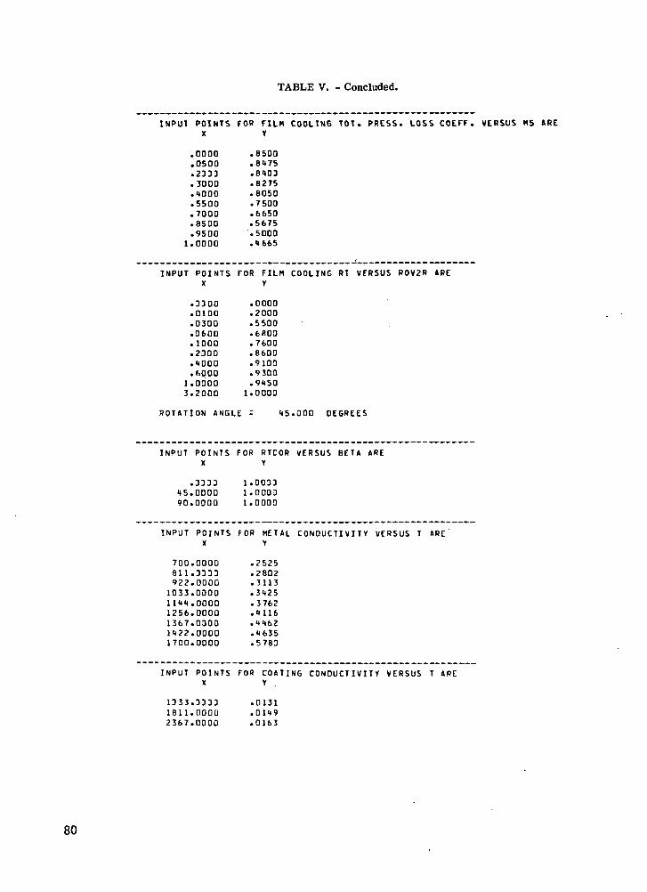
TABLE V. - Concluded.
INPUT POINTSX
.0000
.0500
.2333
.3000
.0000
.5500
.7000
.8500
.95001.0000
INPUT POINTSX
.3300
.0100
.0300
.0600
.1000
.2000
."4000
.60001.03003.2000
FOR FILM COOLTNG TOT. PRESS. LOSS COEFF.V
.8500
.8475
.8403
.8275
.8050
.7500
.6650
.5675
.5000
.4665
FOR FILM COOLING RT VERSUS ROV2R AREY
.0000
.2000
.5500
.6600
.7600
.8600
.9100
.9300
.94501.0000
ROTATION ANGLE : 45.000 DEGREES
INPUT POINTSX
.333345.000090.0000
INPUT POINTSX
700.0000811.3333922.0000
1033. ODOO1144.00001256.00001367.03001422.00001700.0000
INPUT POINTSX
1333.33331811.00002367.0000
FOR RTCOR VERSUS BETA AREY
1.00331.00031.0000
FOR METAL CONDUCTIVITY VERSUS T AREY
.2525
.2802
.3113
.3425
.3762
.4116
.446Z
.4635
.5783
FOR COATING CONDUCTIVITY VERSUS T AREY
.0131
.0149
.0163
80

TABLE VI. - EXAMPLE 1 (VANE) CHAMBER OUTPUT
-OUTPUT FO« CHIflBCR 1-
SI SIS UP OF UNITS
COOHNI GAS CONSTANT; 297.050 J/IK6-KI
THIS CASE INCLUDES * THERMAL BARRIER COATING
3 BOUS OF InPINGEMENI HOLES
Ron HOLES DIAhETER (NHI HOLESPACING
IHPINSEIIENTDISTANCE
RIIHHI
.3018• 3048.3048
.635
.635
.635
2.0832.0832.083
3.BIO
3.8103.810
1.2701.2701.270
.000
.000
.000
101.UUU101.oou001.000
0 BOWS OF FILH COOLING HOLES
HOH HOLES D I A M E T E R 1MB I THICKNESS L/DUALL COATIN6 ( T O T A L I
HOLESPACIN6
ALPHAIOEGI
BETAIOE6I
RHOV?G<K6/H*HR**Z )
t>« PiINNI IN/Ctl«»2)
1 IS .2790 1.270 .127 7.779 2.SHU 10.00U .DUO .13610*07 .3201U*1J2 15 .2790 1.270 .127 8.121 2.500 38.000 .300 .07810*07 .38720*133 15 .2791 1.270 .127 8.717 2.500 35.1100 . D U O .51070-0' .11390*131 15 .2510 1.270 .127 10.098 2.510 33.000 .000 .55900*07 .53620*13
.OOU 3 7 3 . O U U
.000 370 .BOO
.000 368. illO
.OOU 361.70U
IRPINGtHENf AND FILM COOLING FLOWS H A V E CONVERGED IN 8 OVERALL ITERATIONS
INFI0« EOUALS 20.263 K6/HR
IHP PSPLtTHOV <N/C»<«*2>
1 101. UOO2 101. OUO3 4C4.UUO
P2
390.971390.971390.971
B?
.221
.221
.221
T2TIK>
811.611.811.
T2
801801801
UIHP COI«PtKG/HRI
6.751 .8216.751 .8216.751 .821
OUTFLOW EOUALS 20.259 KG/HR
FCHUM
1234
P3TIN/
39039039039U
CK..2
.971
.971
.971
.971
'371371369366
PI
.327
.911
.816
.122
HI
. 191
.205
.217
.235
TITIKI
991 .
982.971.
1001.
T1 / P5T P5/<S/CM««2I
987. /975. /963. /991. /
382.381.380.379.
918766726010
373.370.368.361.
100800503703
IKI / IKI iKs/HRi coRR
.195 1029. 1022./1023. 1.833 .810 .939 1.000
.210 1020. 1012./1011. 5.176 .839 .937 l . O O U
.222 1012. 1003./1005. 5.167 .838 .936 1.000
.212 1U11. 1033./1037. 1.783 .836 .935 1.000
RHOVSO IT9SR A T I O R A T I O
1 .2831 .2561.2131 .200
.768
.730
.709
.687
HEAT TRANSFER RESULTS
FC HE •I-IRANSFER-COEFFKIENTSHOW HGO HG1 FC-HOLE IriPG
<J/<«»»2«SEC«K1>
1 5277. 3972.2 5816. 1256.3 6381. 1183*1 6961. 1761*
9133.10110.
10i97.10915.
6890.«B92.
8882.8908.
H-HOD-FACTORSFC-HOLE IHPG
1.000l.OUO1.000i.aoo
1.0001.000i.aoo1.000
COOLED GAS UALL- IEKPERATUREAREA UUP OUTSIDE I4IFACE INSIOE
<CF1««ZI IKI IKI IKI IKI
.968 2550. 1531. 1232. 1132.
.968 2550. 1513. 1231. 1133.
.96B 2550. 1512. I22«. 1129.
.963 2550. 1562. 1211. Mil .
AVG.-IHERH.-COND.M E T A L C O A T I N GIJ/ICn«SEC*KII
.388
.389
.387
.391
.011
.011
.011
.011
E T AI T C O - T C I /IIUO-TCI
.3011
.2856
.2713
.3101
81

TABLE VII. - EXAMPLE 2 (BLADE) CHAMBER OUTPUT
T H l i C f l S F
i 22 33 24 25 2b 21 2n 2v 2
IU 211 212 2n 2
15 2
-- — — uu i rui r UK ( . H M ^ B t H £
N C L U D E S C E N T R I F U G A L E F F E C T S . R O T A T I O N A L
."1318
.1)318
.4318.4318.4310.4316.4316.4318.4318.4318.4318.4318.4318
.4316
F
T H I C K N E S S
.361 . 82
.361 . 82
.381 . 82
.361 . 62
.381 . 82
.381 . 82
.381 . 82
.381 . 82
. 8 1 . 8 2
. 8 1 . 8 2
. 8 1 . 8 2
. 8 1 . 8 2
. 8 1 . 8 2
. 8 1 . 8 2
.381 . 82
S P E E D t O U A L S 16825.00 R P n .
HOLE H t P I N E E n E H T R l
3.81U .762 217.2003.8103.8103.8103.8103.8103.8103.8103.8103.8103.8103.8103.810
62 217.70062 222.30062 221). 80062 227.30062 229.90062 232.100
62 235.00062 Z 3 7 . S D O62 210. UUO62 212.60062 2*5.10062 207 .700
3.810 .762 252.700
P I T
281.300286.100288.500290.700293. 000295. 200297.600299. *>OQ302. 30U301 .SOU307.300
309. BOO312. 10U
317.800
1
£5*bb7
V
u1'£34
5
2 .45722 .45722 .45722 .4572
2 .45722 .45722 .45722 .45722 .45722 .45722 .45722 .45722 .4572
2 .4572
.01,01.01
.01
.01
.Ul
.01
.Ul
.01
.01
.Ul
.01
.01
.DUO
.300
.000
.000
.000
.000
.000
.000
.300
.000
.3UO
L / D
4 .44 .44.4
4 .44 .44 .44 .44 .44 .4
4 . 4 4
4 .44
HOLE
1 S P A C I N G
2.540
2.54C2. 5402.5 U2.5 02.5 02.5 U
4 2 .54Q
A L P H A( O E S t
30.000
30 .0UU30.UOU
30.0003 U . O O O3D.ODO
30.DOU
B E T A
I D E 6 I
.QUO
.000
.000
.000
.000
.000
.ouo
R K Q V 5
.51620*07
.52000*07
.52190*07
R H O V 2 G
.60150*13
.60440*13
.60720*13
R4
217.200
222 -300224. BOO
229.900232.400235. GOD
Ph
264.500
266.U3J2SE..SUJ
268.400269. 2LJO269. V U U
IHPINb'tMENI
INFLOW
IMP PSPLTTwow |N/C"«*2>
3 266.*tJO1 290.700
6 295. 20C7 297. 6UD
10 3U1.8UO
12 309.80013 312. 1UO11 315>luD15 317. 000
IND FILM COOL1N6 F L O W S H A V E CONVERGED lit
EQUALS 23.152
P2
276.
278.
282.
281.
291 .
296.
298.
301.
303.
P3I PIy IN/cn«*2t
271 .933 261
273.921 265276. 02» 266278.092 266
282.126 268
206 .926 27U
291 .5U5 271293.951 272
298. 896 271301. 367 271
3 3U3.921 275
.612
.360
.178
.993
.621
.151
.771
.592
.111
.916
. /21
028 .092 .
126610 .
926 .
505 .
351 .896 .387 .921 .
til
.150
.162
.173
. 181
.201
.221
.212
.252
.27U
.27V
.2BI
112
256257
256257256
257
257256257258
111IKI
• 11.811.
811 .Bll.
ell.
<m .
en .Ell.
all .?ll .Rll .
KG/HR
721(K l
811.
811.
811.
811.
811.
811.
811.
811.
811.
12 „INP
9 OVERALL I T E R A T I O N S
CDIHP(K6/HRI
802.
802.
802.
802.
802 .
8U2 .
802.
802.
802.
802.
11 / P57/(1/CH**2I
R08./
807. /607. /
606. /
805. /
801. /
P03./802. /
801. /600. /799. /
26S.533269.93327] .111
J72.933
276. U21
279.161
287.3972B1. 103
287.198289.231290.991
:f
t
•i.i.i.i.
198512
533553558
590
612622612658
P5
26126S
266266
268
269
271272
273271275
.500
.200
.003
.BOU
.1110
.900
.501)
.30J
- S O U
.600
.100
.828
.828
.828
.828
.828
.828
.828
.828
.828
.828
.828
B5 75TIKI
.150 811.
.162 811.
.173 811.
.lai an.
.201 811.
.221 811.
.213 nil.
.252 811.
.271 811.
.279 811.
.286 all.
15 / F C T I F/ III
BOB./ 0.807. / 0.3U7./ 0.806. / H.
805. / 0.
8U1./ 0.
803. / 0.802. / 0.
BUI./ 3.800. / 0.799. / u.
82

•B—S 5 3—3 V
0 O O O O O0 O 0 O 0 O 00 0 0 0 0 O
0 0 0 0 0 00 0 0 0 0
0 0 0 0 0 0
0 0 0 0 0 0
0 0 0 0 0 0
0 0 0 0 0 0
0 0 0 0 0 0
0 0 0 0 0 0
83

Tip C-
Chordwise film-cooling row
Figure 4. - Vane chamber division.
Impingementrows
Tip f_
•- Impingementrows
Chordwise film-cooling rows
Figure 5. - Blade chamber division.
84
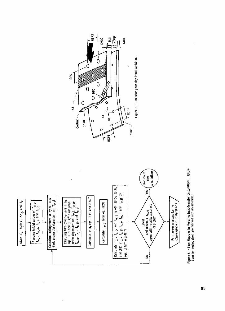
(Jl̂
•g«7
CT*
S"xS
01£
0°
1CJ
6
•-*"0.<_J
^_ »—Om "oCD C13 ro
5 •-«H."
|J-3 ™tn
^K? 3 -O
3 =O t
3 ~.£ &
34)
3
6 S=o-
s s: s?-2 S s
8-
IIS's=§"8te-e±; <o£ »
E ro
IsS s
Sf c= .2
85

Impingement /"rows:
Chamber
Film-cooling rows: 4 3 2 1
Impinge-mentrow123
Number ofholes per
row151515
Holediameter,
cm0.0508.0508.0508
Film-cooling
row
1234
Number ofholes per
row
15
Hole diameter,cm
0.04064.04064.04064.0381
Main-streamstatic
pressure,
N/cm2
373.4370.8368.5364.7
Main-streamdensitytimes
velocity,pv,
kg/(m2- hr)
4. 364X106
4.7815.1075.590
Ma in -streamdensitytimes
velocitysquared,
pv2,kg/(m • hr2)
3. 204xl013
3.8724.4395. 362xl012
Main-streamHGO,a
J/(m2 • sec • K)
5277581663846951
Main-streamHGl.b
J/(m2 • sec • K)
3972425644834767
aMain-stream-gas heat-transfer coefficient for coolant temperature equal to main-stream gas temperature.''Main-stream-gas heat-transfer coefficient for coolant temperature equal to shell outer temperature.
Figure 8. - Vane chamber of example 1.
86

I1-g
is
Is
3,iT
? i3 E
o /o
0 00 O O O Of Q O O O'/—7 0— 0 — 0 — 0— 0— Of iO/—jO— 0—0 —Qi-'O*-JQ o o o o to'-jo £=jb~~'5'~p—«J
0 0 0 0 0 0 0 0 0 0 00 0 0 0 0 0 0 0 0 0 00 0 0 0 . 0 0 0 0 . 0 0 0
0 0 0 0 0 0 0 0 0 0 00 0 0 0 0 0 0 0 0 0 0
0 0 0 0 0 0 0 0 0 0 00 0 0 0 0 0 0 0 0 0 0 I
O O O O O O O Q O O O
O Q O Q Q Q O o o o o o0 0 0 0 0 0 0 0 0 0 0 00 0 0 0 0 0 0 0 0 0 0 0 0
O O O O Q O O 0 0 0 0 0
f .&„,.£• ̂
•- s ̂
Cxi
87

1. Report No. NASA TP-1259 2. Government Accession No.
AVRADCOM TR 78-19(PL)4. Title and Subtitle
FORTRAN PROGRAM FOR CALCULATING COOLANT FLOWAND METAL TEMPERATURES OF A FULL -COVERAGE -FILM-COOLED VANE OR BLADE
7. Author(s)
Peter L. Meitner
9. Performing Organization Name and Address
NASA Lewis Research Center andAVRADCOM Research and Technology LaboratoriesCleveland, Ohio 44135
12. Sponsoring Agency Name and Address
National Aeronautics and Space AdministrationWashington, D.C. 20546 and U.S. Army Aviation Research andDevelopment Command, St. Louis, Mo. '63166
3. Recipient's Catalog No.
5. Report DateJuly 1978
6. Performing Organization Code
8. Performing Organization Report No.
E-9491
10. Work Unit No.
505-0411. Contract or Grant No.
13. Type of Report and Period Covered
Technical Paper
14. Sponsoring Agency Code
15. Supplementary Notes
16. AbstractA computer program that calculates the coolant flow and the metal temperatures of a full-cover age-film-cooled vane or blade has been developed. The analysis is based on com-pressible, one-dimensional fluid flow and on one-dimensional heat transfer and treats the vaneor blade shell as a porous wall. The calculated temperatures are average values for theshell outer-surf ace area associated with each film-cooling hole row. A thermal-barrier coatingmay be specified on the shell outer surface, and centrifugal effects can be included for bladecalculations. The program is written in FORTRAN IV and is operational on a UNTVAC 1100/42computer. This report describes the method of analysis, the program input, the program out-put, and two example problems and provides a program listing.
17. Key Words (Suggested by Author(sl)
Heat transferTurbine coolingFilm coolingFull -coverage film cooling
19. Security dassif. (of this report)Unclassified
18. Distribution StatementUnclassified - unlimitedSTAR Category 07
20. Security Classif. (of this page) 21 . No. oUnclassified 9
f Pages 22. Price'0 A05
* For sale by the National Technical Information Service, Springfield, Virginia 22161NASA-Langley, 1978

National Aeronautics andSpace Administration
Washington, D.C.20546
Official BusinessPenalty for Private Use, $300
THIRD-CLASS BULK RATE Postage and Fees PaidNational Aeronautics andSpace AdministrationNASA-451
US. MAIL
NASA POSTMASTER: If Undeliverable (Section 158Postal Manual) Do Not Return