A Three-Dimensional Coupled Internal/External Simulation ... · A THREE-DIMENSIONAL COUPLED...
22
James D. Heidmann Glenn Research Center, Cleveland, Ohio David L. Rigby Dynacs Engineering Co., Inc., Brook Park, Ohio Ali A. Ameri AYT Corporation, Cleveland, Ohio A Three-Dimensional Coupled Internal/External Simulation of a Film-Cooled Turbine Vane NASA/TM—1999-209078 April 1999 https://ntrs.nasa.gov/search.jsp?R=19990052582 2018-09-07T23:07:12+00:00Z
Transcript of A Three-Dimensional Coupled Internal/External Simulation ... · A THREE-DIMENSIONAL COUPLED...
James D. HeidmannGlenn Research Center, Cleveland, Ohio
David L. RigbyDynacs Engineering Co., Inc., Brook Park, Ohio
Ali A. AmeriAYT Corporation, Cleveland, Ohio
A Three-Dimensional CoupledInternal/External Simulationof a Film-Cooled Turbine Vane
NASA/TM—1999-209078
April 1999
https://ntrs.nasa.gov/search.jsp?R=19990052582 2018-09-07T23:07:12+00:00Z

The NASA STI Program Office . . . in Profile
Since its founding, NASA has been dedicated tothe advancement of aeronautics and spacescience. The NASA Scientific and TechnicalInformation (STI) Program Office plays a key partin helping NASA maintain this important role.
The NASA STI Program Office is operated byLangley Research Center, the Lead Center forNASA’s scientific and technical information. TheNASA STI Program Office provides access to theNASA STI Database, the largest collection ofaeronautical and space science STI in the world.The Program Office is also NASA’s institutionalmechanism for disseminating the results of itsresearch and development activities. These resultsare published by NASA in the NASA STI ReportSeries, which includes the following report types:
• TECHNICAL PUBLICATION. Reports ofcompleted research or a major significantphase of research that present the results ofNASA programs and include extensive dataor theoretical analysis. Includes compilationsof significant scientific and technical data andinformation deemed to be of continuingreference value. NASA’s counterpart of peer-reviewed formal professional papers buthas less stringent limitations on manuscriptlength and extent of graphic presentations.
• TECHNICAL MEMORANDUM. Scientificand technical findings that are preliminary orof specialized interest, e.g., quick releasereports, working papers, and bibliographiesthat contain minimal annotation. Does notcontain extensive analysis.
• CONTRACTOR REPORT. Scientific andtechnical findings by NASA-sponsoredcontractors and grantees.
• CONFERENCE PUBLICATION. Collectedpapers from scientific and technicalconferences, symposia, seminars, or othermeetings sponsored or cosponsored byNASA.
• SPECIAL PUBLICATION. Scientific,technical, or historical information fromNASA programs, projects, and missions,often concerned with subjects havingsubstantial public interest.
• TECHNICAL TRANSLATION. English-language translations of foreign scientificand technical material pertinent to NASA’smission.
Specialized services that complement the STIProgram Office’s diverse offerings includecreating custom thesauri, building customizeddata bases, organizing and publishing researchresults . . . even providing videos.
For more information about the NASA STIProgram Office, see the following:
• Access the NASA STI Program Home Pageat http://www.sti.nasa.gov
• E-mail your question via the Internet [email protected]
• Fax your question to the NASA AccessHelp Desk at (301) 621-0134
• Telephone the NASA Access Help Desk at(301) 621-0390
• Write to: NASA Access Help Desk NASA Center for AeroSpace Information 7121 Standard Drive Hanover, MD 21076
James D. HeidmannGlenn Research Center, Cleveland, Ohio
David L. RigbyDynacs Engineering Co., Inc., Brook Park, Ohio
Ali A. AmeriAYT Corporation, Cleveland, Ohio
A Three-Dimensional CoupledInternal/External Simulationof a Film-Cooled Turbine Vane
NASA/TM—1999-209078
April 1999
National Aeronautics andSpace Administration
Glenn Research Center
Prepared for the44th Gas Turbine and Aeroengine Congress, Exposition, and Users' Symposiumsponsored by the International Gas Turbine Institute ofthe American Society of Mechanical EngineersIndianapolis, Indiana, June 7–10, 1999

Available from
NASA Center for Aerospace Information7121 Standard DriveHanover, MD 21076Price Code: A03
National Technical Information Service5285 Port Royal RoadSpringfield, VA 22100
Price Code: A03
A THREE-DIMENSIONAL COUPLED INTERNAL/EXTERNAL SIMULATION OF AFILM-COOLED TURBINE VANE
James D. HeidmannNASA Glenn Research Center
Cleveland, OH 44135
David L. RigbyDynacs Engineering Co., Inc.
Brook Park, OH 44142
Ali A. AmeriAYT Corporation
NASA Glenn Research GroupCleveland, OH 44135
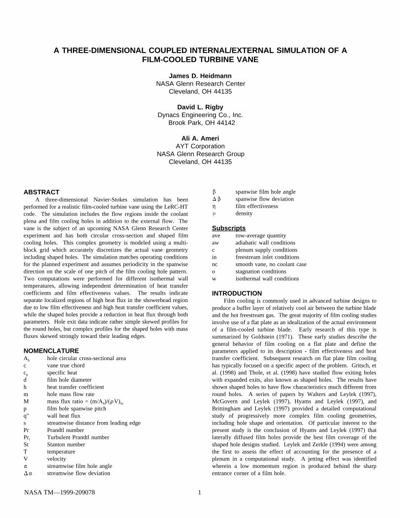
ABSTRACTA three-dimensional Navier-Stokes simulation has been
performed for a realistic film-cooled turbine vane using the LeRC-HTcode. The simulation includes the flow regions inside the coolantplena and film cooling holes in addition to the external flow. Thevane is the subject of an upcoming NASA Glenn Research Centerexperiment and has both circular cross-section and shaped filmcooling holes. This complex geometry is modeled using a multi-block grid which accurately discretizes the actual vane geometryincluding shaped holes. The simulation matches operating conditionsfor the planned experiment and assumes periodicity in the spanwisedirection on the scale of one pitch of the film cooling hole pattern.Two computations were performed for different isothermal walltemperatures, allowing independent determination of heat transfercoefficients and film effectiveness values. The results indicateseparate localized regions of high heat flux in the showerhead regiondue to low film effectiveness and high heat transfer coefficient values,while the shaped holes provide a reduction in heat flux through bothparameters. Hole exit data indicate rather simple skewed profiles forthe round holes, but complex profiles for the shaped holes with massfluxes skewed strongly toward their leading edges.
NOMENCLATUREA hole circular cross-sectional areah
c vane true chordc specific heatp
d film hole diameterh heat transfer coefficientm hole mass flow rateM mass flux ratio = (m/A )/( V)h in
p film hole spanwise pitchq" wall heat fluxs streamwise distance from leading edgePr Prandtl numberPr Turbulent Prandtl numbert
St Stanton numberT temperatureV velocity
streamwise film hole anglestreamwise flow deviation
spanwise film hole anglespanwise flow deviationfilm effectivenessdensity
Subscriptsave row-average quantityaw adiabatic wall conditionsc plenum supply conditionsin freestream inlet conditionsnc smooth vane, no coolant caseo stagnation conditionsw isothermal wall conditions
INTRODUCTIONFilm cooling is commonly used in advanced turbine designs to
produce a buffer layer of relatively cool air between the turbine bladeand the hot freestream gas. The great majority of film cooling studiesinvolve use of a flat plate as an idealization of the actual environmentof a film-cooled turbine blade. Early research of this type issummarized by Goldstein (1971). These early studies describe thegeneral behavior of film cooling on a flat plate and define theparameters applied to its description - film effectiveness and heattransfer coefficient. Subsequent research on flat plate film coolinghas typically focused on a specific aspect of the problem. Gritsch, etal. (1998) and Thole, et al. (1998) have studied flow exiting holeswith expanded exits, also known as shaped holes. The results haveshown shaped holes to have flow characteristics much different fromround holes. A series of papers by Walters and Leylek (1997),McGovern and Leylek (1997), Hyams and Leylek (1997), andBrittingham and Leylek (1997) provided a detailed computationalstudy of progressively more complex film cooling geometries,including hole shape and orientation. Of particular interest to thepresent study is the conclusion of Hyams and Leylek (1997) thatlaterally diffused film holes provide the best film coverage of theshaped hole designs studied. Leylek and Zerkle (1994) were amongthe first to assess the effect of accounting for the presence of aplenum in a computational study. A jetting effect was identifiedwherein a low momentum region is produced behind the sharpentrance corner of a film hole.
NASA TM—1999-209078 1
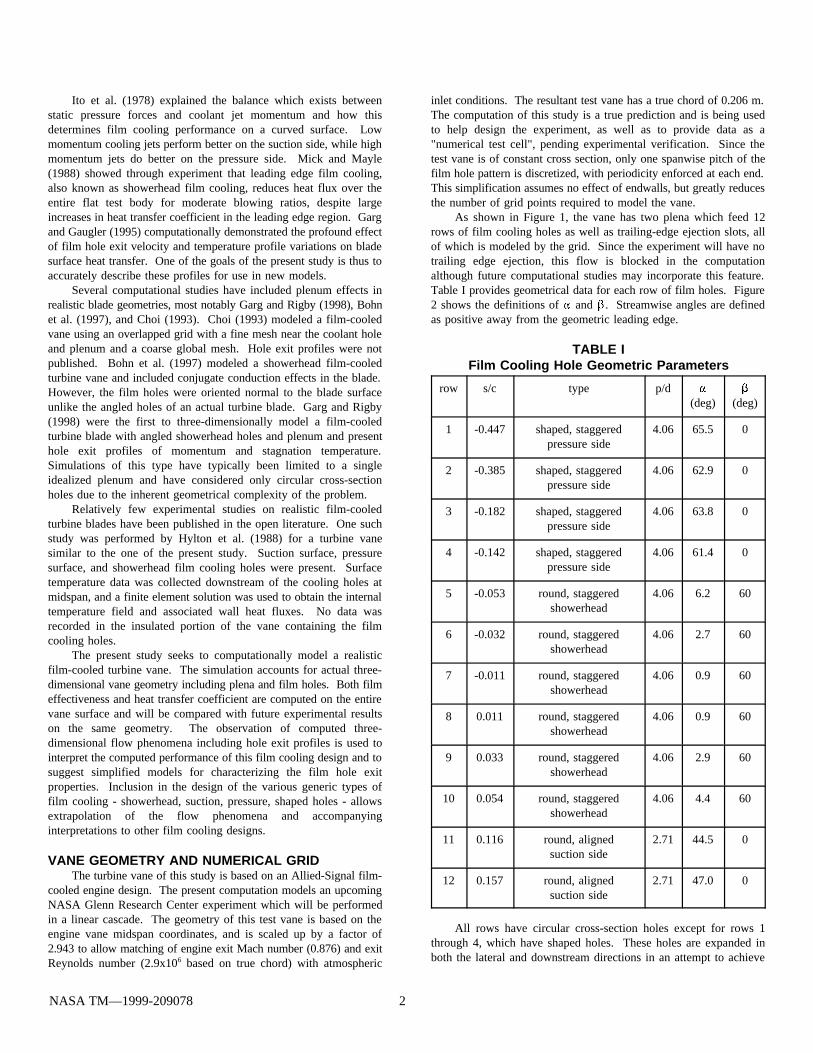
Ito et al. (1978) explained the balance which exists betweenstatic pressure forces and coolant jet momentum and how thisdetermines film cooling performance on a curved surface. Lowmomentum cooling jets perform better on the suction side, while highmomentum jets do better on the pressure side. Mick and Mayle(1988) showed through experiment that leading edge film cooling,also known as showerhead film cooling, reduces heat flux over theentire flat test body for moderate blowing ratios, despite largeincreases in heat transfer coefficient in the leading edge region. Gargand Gaugler (1995) computationally demonstrated the profound effectof film hole exit velocity and temperature profile variations on bladesurface heat transfer. One of the goals of the present study is thus toaccurately describe these profiles for use in new models.
Several computational studies have included plenum effects inrealistic blade geometries, most notably Garg and Rigby (1998), Bohnet al. (1997), and Choi (1993). Choi (1993) modeled a film-cooledvane using an overlapped grid with a fine mesh near the coolant holeand plenum and a coarse global mesh. Hole exit profiles were notpublished. Bohn et al. (1997) modeled a showerhead film-cooledturbine vane and included conjugate conduction effects in the blade.However, the film holes were oriented normal to the blade surfaceunlike the angled holes of an actual turbine blade. Garg and Rigby(1998) were the first to three-dimensionally model a film-cooledturbine blade with angled showerhead holes and plenum and presenthole exit profiles of momentum and stagnation temperature.Simulations of this type have typically been limited to a singleidealized plenum and have considered only circular cross-sectionholes due to the inherent geometrical complexity of the problem.
Relatively few experimental studies on realistic film-cooledturbine blades have been published in the open literature. One suchstudy was performed by Hylton et al. (1988) for a turbine vanesimilar to the one of the present study. Suction surface, pressuresurface, and showerhead film cooling holes were present. Surfacetemperature data was collected downstream of the cooling holes atmidspan, and a finite element solution was used to obtain the internaltemperature field and associated wall heat fluxes. No data wasrecorded in the insulated portion of the vane containing the filmcooling holes.
The present study seeks to computationally model a realisticfilm-cooled turbine vane. The simulation accounts for actual three-dimensional vane geometry including plena and film holes. Both filmeffectiveness and heat transfer coefficient are computed on the entirevane surface and will be compared with future experimental resultson the same geometry. The observation of computed three-dimensional flow phenomena including hole exit profiles is used tointerpret the computed performance of this film cooling design and tosuggest simplified models for characterizing the film hole exitproperties. Inclusion in the design of the various generic types offilm cooling - showerhead, suction, pressure, shaped holes - allowsextrapolation of the flow phenomena and accompanyinginterpretations to other film cooling designs.
VANE GEOMETRY AND NUMERICAL GRIDThe turbine vane of this study is based on an Allied-Signal film-
cooled engine design. The present computation models an upcomingNASA Glenn Research Center experiment which will be performedin a linear cascade. The geometry of this test vane is based on theengine vane midspan coordinates, and is scaled up by a factor of2.943 to allow matching of engine exit Mach number (0.876) and exitReynolds number (2.9x10 based on true chord) with atmospheric6
inlet conditions. The resultant test vane has a true chord of 0.206 m.The computation of this study is a true prediction and is being usedto help design the experiment, as well as to provide data as a"numerical test cell", pending experimental verification. Since thetest vane is of constant cross section, only one spanwise pitch of thefilm hole pattern is discretized, with periodicity enforced at each end.This simplification assumes no effect of endwalls, but greatly reducesthe number of grid points required to model the vane.
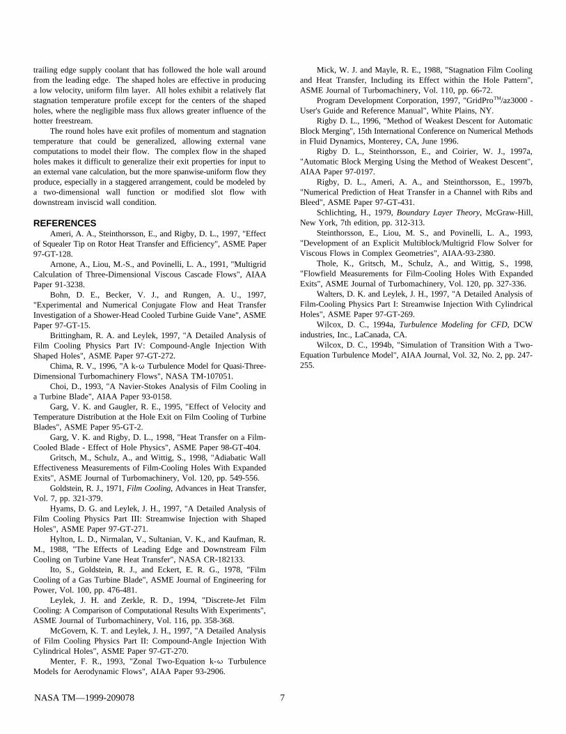
As shown in Figure 1, the vane has two plena which feed 12rows of film cooling holes as well as trailing-edge ejection slots, allof which is modeled by the grid. Since the experiment will have notrailing edge ejection, this flow is blocked in the computationalthough future computational studies may incorporate this feature.Table I provides geometrical data for each row of film holes. Figure2 shows the definitions of and . Streamwise angles are definedas positive away from the geometric leading edge.
TABLE IFilm Cooling Hole Geometric Parameters
row s/c type p/d(deg) (deg)
1 -0.447 shaped, staggeredpressure side
4.06 65.5 0
2 -0.385 shaped, staggeredpressure side
4.06 62.9 0
3 -0.182 shaped, staggeredpressure side
4.06 63.8 0
4 -0.142 shaped, staggeredpressure side
4.06 61.4 0
5 -0.053 round, staggeredshowerhead
4.06 6.2 60
6 -0.032 round, staggeredshowerhead
4.06 2.7 60
7 -0.011 round, staggeredshowerhead
4.06 0.9 60
8 0.011 round, staggeredshowerhead
4.06 0.9 60
9 0.033 round, staggeredshowerhead
4.06 2.9 60
10 0.054 round, staggeredshowerhead
4.06 4.4 60
11 0.116 round, alignedsuction side
2.71 44.5 0
12 0.157 round, alignedsuction side
2.71 47.0 0
All rows have circular cross-section holes except for rows 1through 4, which have shaped holes. These holes are expanded inboth the lateral and downstream directions in an attempt to achieve
NASA TM—1999-209078 2
better film coverage. The expansion angle on each side of the holesand on the downstream edge is 10 deg. Rows 5 through 10 consistof compound-angle holes in the showerhead region which have aninclination of 60 deg. in the spanwise direction. Rows 11 and 12have a spanwise pitch equal to two-thirds of the spanwise pitch ofrows 1 through 10, so the overall vane spanwise pitch covers 3 holeseach in rows 11 and 12, and 2 holes each in rows 1 through 10. Inrows 1 through 10, the holes are in a staggered arrangement, so it wasnecessary to split some holes on the spanwise periodic boundary.
A multi-block grid approach is adopted to model this complexgeometry, in which a system of locally structured grid blocks isgenerated in a globally unstructured assembly. This multi-blocksystem is generated in the present study by the grid generationprogram GridPro (Program Development Corporation, 1997). ThisTM
program produces a body-fitted multi-block grid with hexahedral cellsand full face-matching blocks. The present grid was initiallycomposed of 2298 blocks, which were merged to produce a gridconsisting of 140 blocks using the Method of Weakest Descent asdescribed in Rigby (1996) and Rigby et al. (1997a). The grid iscomposed of 1.2x10 computational cells. Algebraic clustering6
produces a y value of less than 1.0 at the first grid point away from+
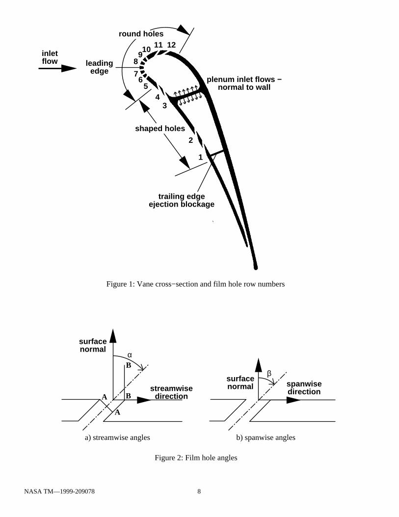
the wall at all locations. Several calculations were performed forvarying wall spacings, and it was found that further reductionsproduced little change in the solution. The grid consists of 20 cellsacross both the inlet and outlet boundaries, 60 cells on the periodicboundary, over 200 cells around the vane, and 44 cells from the vaneto the periodic boundary. These values are consistent with goodcomputational practice. A blade-to-blade view of the computationalgrid is shown in Figure 3.
Figure 4 shows the grid in the leading edge region of the vane.The faithful discretization of the shaped holes should be noted, aswell as the ability of the multi-block grid to transition from a veryfine structure near locations of complex geometry such as film holesto a coarser structure far from the holes. In addition, the clusteredviscous grids abut all wall boundaries without extending into the flowfield. These features would be impossible for a single-block grid oneven modestly complex geometries, and serve to greatly reduce thenumber of grid points necessary to adequately resolve the geometry.
COMPUTATIONAL METHODThe simulations in this study were performed using a multiblock
computer code called LeRC-HT, previously known as TRAF3D.MB(Steinthorsson et al., 1993) which is based on a single block codedesigned by Arnone et al. (1991). This code is a general purposeflow solver designed for simulations of flows in complicatedgeometries. The code solves the full compressible Reynolds-averagedNavier-Stokes equations using a multi-stage Runge-Kutta-basedmultigrid method. It uses the finite volume method to discretize theequations. The code uses central differencing together with artificialdissipation to discretize the convective terms. The overall accuracyof the code is second order. The present version of the code (Rigby,1996, Rigby et al., 1997b and Ameri et al. 1997) employs the k-turbulence model developed by Wilcox (1994a, 1994b), withsubsequent modifications by Menter (1993) as implemented by Chima(1996). The k- turbulence model is desirable because it does notrequire specification of distance to the wall. Such a specification isdifficult for complex geometries requiring multi-block grids, such asis considered in the present study. Accurate heat transfer predictionsare possible with the code because the model integrates to the wallsand no wall functions are used. Rather, the computational grid is
generated to be sufficiently fine near walls to produce a y value of+
less than 1.0 at the first grid point away from the wall. For heattransfer a constant value of 0.9 for turbulent Prandtl number, Pr , ist
used. A constant value of Pr=0.72 is used. Laminar viscosity is afunction of temperature through a 0.7 power law (Schlichting, 1979)and c is taken to be a constant.p
The freestream inlet flow to the vane is at an angle of 0 deg. tothe axial direction, with all temperatures and pressures normalized bythe inlet stagnation values of 294 K and 101 kPa, respectively. Theinlet turbulence intensity is 8.0% and the turbulence scale is 15.0%of vane true chord. These values were based on preliminaryexperimental turbulence grid designs. Other inflow quantities are setby means of the upstream-running Riemann invariant. The vanedownstream exit flow is defined by imposing a constant normalizedstatic pressure of 0.576, which was empirically determined to yieldthe design exit Mach number of 0.876. Periodicity was enforced inboth the blade-to-blade and spanwise directions based on vane andfilm hole pitches, respectively.
To maintain a true periodic solution, inflow to the plena wasprovided by defining a region of each plenum wall as an inlet andintroducing uniform flow normal to the wall. These regions lie oneither side of the internal wall which separates the two plena asshown in Figure 1. The experiment will have spanwise flow in theplenum, but bleed of the plenum flow into the film holes results in aspanwise-varying mass flow rate and static pressure, which wouldviolate spanwise periodicity. Modeling this spanwise plenum flowwas attempted computationally, but was abandoned when numericalinstabilities prevented convergence. The inflow stagnationtemperature to the plena was 0.5, the velocity was fixed to theconstant value required to provide the design mass flow rate to eachplenum, and static pressure was extrapolated from the interior. Theinflow patch for each plenum was defined to be sufficiently large toyield very low inlet velocities (Mach number < 0.05), allowing eachplenum to approximate an ideal plenum.
All solid walls were given a no-slip boundary condition inaddition to a fixed temperature. The isothermal wall boundarycondition extended to all wall surfaces, including the film holesurfaces and plenum surfaces, so heat transfer in the plena and filmholes occurs and provides a stagnation temperature profile in the jetexiting each hole. Two solutions were generated with walltemperatures (T ) of 0.7 and 0.8, respectively. The predicted wallw
heat flux distributions (q ") from these solutions were used to solvew
simultaneously for adiabatic wall temperature (T ) and Stantonaw
number based on adiabatic wall temperature (St ) using equation (1),aw
under the assumption that T and St are independent of T . Havingaw aw w
solved for T , film effectiveness () was found by equation (2) andaw
Stanton number based on inlet stagnation temperature (St ) was foundin
using equation (3) for the 0.7 wall temperature case:
NASA TM—1999-209078 3
T is the inlet stagnation temperature, T is the coolant temperature,in c
and , V, and c are the density, velocity, and specific heat of thep
freestream inlet. St is a dimensionless heat transfer coefficient andaw
may be thought of as the heat transfer coefficient which would resultfor a coolant flow at the same temperature as the freestream. St isin
the dimensionless overall heat transfer coefficient, and is simplyproportional to local wall heat flux for the T =0.7 case. The wallw
temperature of 0.7 is considered the baseline case because it mostclosely matches the temperature of an isothermal cooled turbine vane.Volumetric flow data and wall heat fluxes are given for this case. Athird calculation was performed for a smooth vane with no film holesor plenum at a wall temperature of 0.7. The results of this calculationwere used to normalize the film-cooling predictions.
Computations were performed in parallel fashion on the NASAAmes Research Center CRAY J90 cluster using 8 processors.Approximately 80 J90 hours (20 equivalent C90 hours) were requiredto reach convergence for each calculation. The computations wereconsidered converged when changes to the heat flux after anadditional 300 iterations were no longer noticeable either in contourplots or in graphs of span-averaged data versus surface distance. Thistypically occurred after density residuals had been reduced by morethan three orders of magnitude.
COMPUTATIONAL RESULTSIn lieu of experimental data, the computational results will
initially focus on flow physics and detailed phenomena whichexperiments have difficulty resolving. These results will then bereduced to averaged quantities more amenable to comparison withfuture data. Computational results are organized into four types ofdata: volumetric flow quantities, integrated flow quantities, surfacequantities, and span-averaged surface quantities.
Figure 5 shows the stagnation temperature on a fixed-span planethrough the centerline of the central suction side film holes. It isimmediately evident that the stagnation line intersects this planebetween rows 6 and 7 (the second and third showerhead rows fromthe pressure side) since the high temperature isotherms approach thevane. The freestream impinges at this point, diverting the coolingflow from these rows to opposite sides of the vane. A thinning of thethermal boundary layer is also evident on the pressure side, justupstream of the shaped holes. This will manifest itself as an increasein heat flux at this location. A thermal boundary layer is presentinside the plenum and film holes due to the isothermal boundarycondition there. The resultant stagnation temperature profile in the
film jets is of great interest, as is the velocity profile. Both will beshowcased later in this report.
Figure 6 illustrates the differing behavior of the suction sideround holes and the pressure side shaped holes. In Figures 6(a) and6(b), the stagnation temperature is shown on normal planes justdownstream of rows 3 and 12, respectively. As expected, the shapedholes exhibit improved spreading of the coolant flow in the spanwisedirection. It is also evident that the thermal mixing region issomewhat thicker on the pressure side as expected due to lowerfreestream velocities. On an uncooled blade, this lowers heat transferbecause of smaller temperature gradients and associated heat transfercoefficients. However, on a film-cooled blade, the film effectivenessmay suffer on the pressure side due to enhanced coolant diffusion.In fact, the design of this vane reflects this, as the improvedperformance of the shaped holes is needed on the pressure side tooffset a more rapid decay of film effectiveness. Also worth noting isthe spanwise skewing of the outer thermal boundary layer on thesuction side due to its larger share of spanwise flow from theshowerhead holes.
Figure 7 shows projected velocity vectors on planes near a holein row 12. The planes are defined in Figure 2(a). A pair ofcounterrotating vortices inside the film hole can be seen in Figure7(a). These are caused by a jetting effect as described by Leylek andZerkle (1994). The plenum flow makes a sharp turn around thedownstream edge of the hole inlet, causing a jet to form whichimpinges on the upstream side of the hole. This impingement resultsin a counterrotating pair of vortices which distribute the mass fluxalong the sides of the hole. Figure 7(b) shows a different pair ofcounterrotating vortices outside the film hole which are produced bythe viscous action of the exiting film jet on the surrounding fluid.These vortices encourage entrainment of hot freestream gas andseparation of the cooling jet from the wall. The jetting action whichproduces the vortices inside the film holes is illustrated in Figure 8for a hole in row 2. This behavior is present in some form for allholes, but the shape, angle, length, blowing rate, and location of thehole all have an effect on the flow profiles exiting the hole. Anunderstanding of the jetting effect is required to adequately describehole exit profiles.
To best define the characteristics of flow exiting each row ofholes, it is necessary to present those flow properties which have themost fundamental impact on the external flow and are usable insimplified models. The stagnation temperature is directly related tothe external heat transfer and is thus presented. The flow isrepresented by the momentum magnitude and two flow angles.Streamwise and spanwise flow angle deviation from the holecenterline are chosen to represent the flow direction since film holeexit flow is often assumed to be at the hole geometric angle in theabsence of detailed data. While other quantities such as pressure andturbulence values are also important, they are not presented ininterests of brevity. Figures 9 through 12 present these profiles. Inthese figures, the hole exit plane at the blade surface is shown for onehole in each row, rotated to be viewed along the hole axis. Whilesmall variations exist from hole to hole in a given row, they are smallcompared to the row to row differences. The shaped holes are scaledto appear approximately the same size as the round holes.
Figure 9 shows contours of momentum magnitude. These plotsare normalized by the vane inlet momentum. For the shaped holes,a sharp maximum in momentum occurs along the upstream edge ofthe hole, with elevated levels also near the sides and downstreamedge of the hole. The center of the shaped holes is a very low
NASA TM—1999-209078 4

momentum region. This behavior results from the aforementionedjetting effect. The spanwise and downstream expansion of the shapedholes greatly increase the flow area and correspondingly decrease themomentum in the downstream portion of the holes. The circularholes, on the other hand, have a much more uniform momentumdistribution. The maximum value for these holes depends on theexternal pressure variation as well as the hole orientation. The jettingeffect and counterrotating vortices occur as for the shaped holes, butthe momentum distribution is more uniform because of the lack ofspanwise and downstream expansion. The holes in the stagnationregion (rows 5 through 7) have a maximum momentum near theirtrailing edge, while the suction side showerhead holes (rows 8through 10) have a maximum momentum skewed toward thedownstream direction because of the decreasing external staticpressure. The suction side holes (rows 11 and 12) are quite skewedtoward the downstream direction, although high momentum remnantscan be seen near their leading edge due to the high momentumassociated with these holes. The combined effect produces aninverted momentum profile, where the maximum values lie in a ringaround the lower momentum region in the center of the hole.
Figure 10 shows the stagnation temperature profiles for each rowof holes. These plots are normalized by the plenum inlet and walltemperatures. Temperatures closer to the plenum inlet temperaturetend to occur at locations of high momentum because this fluid hasbeen influenced less by the warmer plenum and hole walls. Becauseof this phenomenon, it should be possible to correlate the stagnationtemperature with momentum, much as it is for a fully developedchannel flow with heat transfer. It would then only be necessary tomodel the hole exit momentum to obtain both parameters. The highertemperatures near the center of the shaped holes result from the lowmomentum, which allows the warmer external flow to approach thehole exit plane as seen also in Figure 5.
Figure 11 presents profiles of streamwise flow angle relative tothe hole geometric streamwise angle. Positive values representdeflections away from the vane leading edge. The low momentumregions of the shaped holes show large streamwise deflections in thestreamwise direction due to the downstream diffusion of the hole. Infact, the flow in this region is nearly parallel to the vane surface.This observation is corroborated by Figure 8. The shaped holes alsoexhibit a thin region of flow nearly aligned with the hole angle at theupstream edge. This coincides with the high momentum region ofFigure 9, and indicates that a large fraction of the mass flux in theshaped holes occurs in this region. It may thus be possible to modelthe flow from these shaped holes as if it were issuing from a thin slotwith an inviscid boundary condition immediately downstreamrepresenting the low flux region near the hole center.
The behavior of the showerhead holes (rows 5-10) in Figure 11is easily explainable in terms of the counterrotating vorticesassociated with the jetting effect. For all these holes, clockwise andcounterclockwise vortices exist on the left and right sides of the hole,respectively, as viewed in Figure 11. Thus the flow at the bottom ofeach hole is away from the centerline, while the opposite is true at thetop. As the holes get farther from the stagnation line such as at rows9 and 10, the flow from the entire hole is deflected downstream, butthe vortex effect is still present and is superimposed on the overalldeflection angle. Rows 11 and 12 exhibit very little gradient instreamwise deflection angle, and generally have a small deflectiontoward the leading edge due to the large jetting effect associated withtheir high momentum.
Figure 12 presents contours of spanwise deflection angle, defined
as flow spanwise angle relative to the hole geometric spanwise angle.Here deflection angles in the showerhead injection direction arepositive. The shaped holes have a simple behavior, with flow movingaway from the centerline due to spanwise diffusion, although row 4exhibits a skewed profile due to deflection from the showerheadholes. The showerhead holes again are subject to the vortex behavior,with flow tending to move away from the showerhead injectiondirection along the centerline and toward it on the edges. A similareffect can be inferred in the suction side holes of rows 11 and 12,with a deflection toward the showerhead direction caused by theshowerhead flow, especially in row 11.
Table II presents row-average mass flux and stagnationtemperature ratios for each row of holes. The mass flux ratios aregiven in relation to the upstream mass flux. For shaped holes, themass flux is based on their circular inlet cross-section. It can be seenthat the suction side holes have the highest mass flow rate because oftheir low exit static pressure. Although the mass flux ratio seemshigh for the suction side holes, their mass flux ratio based on localrather than inlet freestream mass flux is actually about 1.1. Thelowest mass flux ratios occur near the stagnation region (rows 5-7)due to the high exit static pressure. The stagnation temperatures areslightly above the plenum inlet temperature of 0.5 due to heat transferin the plenum and hole pipes. The deviation from 0.5 correlatesgenerally with the amount of plenum wall heat transfer areasurrounding each row.
TABLE IIFilm Cooling Hole Row-Average Flow Parameters
row M=(m/A )/( V)h in T /To,ave o,in
1 2.36 0.536
2 2.08 0.525
3 2.79 0.525
4 2.47 0.526
5 2.02 0.525
6 1.99 0.519
7 2.16 0.519
8 2.25 0.518
9 2.69 0.516
10 2.75 0.514
11 3.41 0.513
12 3.66 0.527
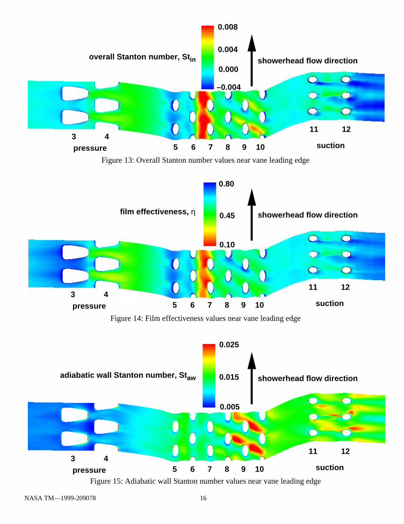
Figures 13 through 15 present local wall heat transfer data forthe leading edge region of the vane. The spanwise variations aregreatest on this portion of the vane. Span-averaged results will bepresented for the entire vane. Figure 13 presents the wall heat fluxnondimensionalized as overall Stanton number for a wall temperatureof 0.7. It should be noted that overall Stanton number may be eitherpositive (heat flux into the vane) or negative (heat flux from vane to
NASA TM—1999-209078 5
flow) because the wall temperature is between the freestream andcoolant temperatures. The largest heat flux occurs along the stagnationline, between rows 6 and 7, where coolant is not present. Heat fluxis also high in streaks between jets on the suction side portion of theshowerhead region, and between the holes in the first row of shapedholes on the pressure side. While knowledge of heat flux isimportant, it is more illuminating to know the relative contributionsto heat flux of film effectiveness (adiabatic wall temperature) and heattransfer coefficient. The second solution for wall temperature of 0.8allows determination of St and T through equation 1 by assumingaw aw
St to be the same for both solutions at all locations. Filmaw
effectiveness is then simply found by equation 2.Film effectiveness is the primary determinant of heat flux, and
is shown on the vane surface in Figure 14. The stagnation line andthe region near row 4 exhibit a low film effectiveness, which simplymeans the driving temperature for heat transfer is near the freestreamtemperature. This is consistent with the behavior shown in Figure 13.However, the high heat flux region near rows 9 and 10 in Figure 13is not accompanied by a low film effectiveness. For an explanationof this behavior, the heat transfer coefficient data must be examined,shown in Figure 15 nondimensionalized as adiabatic wall Stantonnumber. A pronounced maximum in St is apparent in the veryaw
location of the high heat flux, which explains its existence. Here thedriving temperature for heat transfer is not much above the walltemperature, but the intense mixing associated with the showerheadjets interacting with the accelerating freestream causes the heat fluxto increase. An interesting phenomenon occurs downstream of thesuction side film holes. Although the heat transfer coefficient is highin the regions of high vorticity shown in Figure 7(b), the drivingtemperature for heat transfer is below the wall temperature as shownin Figure 14, resulting in large negative heat flux (Figure 13). Thisillustrates the dependence of wall heat flux on wall temperature. Filmeffectiveness and heat transfer coefficient are independent of walltemperature by this model.
Figures 16 through 18 present the span-averaged filmeffectiveness, Stanton numbers, and Stanton number ratios,respectively. Span-averages near film holes exclude the hole exitplanes. The locations of film hole centerlines are shown by verticaldashed lines. The high Stanton numbers on the pressure side trailingedge result from both low film effectiveness and high heat transfercoefficient. The vane is designed for trailing edge coolant ejectionwhich was not considered in this simulation. This highlights thenecessity of using this method of cooling. However, the primaryfocus of this study is the film cooling performance of the twelveexisting film cooling rows.
In Figure 17, a high overall Stanton number at the stagnation lineis apparent, but this occurs over a very short streamwise distance, andits effects would likely be mitigated in a conducting metal vane. Aregion which seems to be of more concern is that between theshowerhead holes and the first row of holes on the pressure side.This represents the largest integrated heat flux in the forward portionof the vane. It results from the fact that most of the showerheadcoolant goes to the suction side. The adiabatic wall Stanton numberis not tremendously high in this region, but the film effectiveness isquite low, indicating a lack of coolant coverage, as shown in Figures14 and 16. This phenomenon is exhibited to a lesser extent justupstream of the last two rows on the pressure side. A region of veryhigh overall Stanton number is predicted on the aft portion of thesuction side. Unlike the pressure side, this behavior would not beaffected by inclusion of trailing edge coolant ejection in this constant
wall temperature prediction. However, in a conducting vane, the highvelocity internal coolant flow associated with trailing edge ejectionshould keep temperatures low in the thin aft portion of the vane.
As noted previously, the suction side film holes provide a regionof large negative heat flux. The film effectiveness actually peakssome distance downstream of the last row of holes, indicating a smalljet separation and reattachment. This is unlike the pressure side rows,where a sharp maximum in film effectiveness is reached at the holeexit followed by a rapid decrease. This rapid decrease accounts forthe small region of positive heat flux between the two sets of pressureside holes, but the effect is mitigated by the very low heat transfercoefficient provided by the shaped holes.
Figure 18 shows both the overall and adiabatic wall Stantonnumbers normalized by the Stanton number for the smooth vanecalculation with no coolant. The adiabatic wall Stanton number isgreater than 1.0 at nearly all locations, indicating that the presence offilm cooling increases heat transfer coefficient over the entire vane.The ratio dips below 1.0 downstream of the last pressure side row dueto the low velocity flow exiting the diffusing holes. The overallStanton number ratio is less than 1.0 at nearly all locations, indicatingthat the film-cooled vane heat flux is everywhere less than for theuncooled vane, as expected. The only small exception occurs rightat the stagnation point, where the ratio barely exceeds 1.0 due to thevery low film effectiveness and enhanced heat transfer coefficient inthis region.
SUMMARY AND CONCLUSIONSA computational study has been performed on a realistic film-
cooled turbine vane in anticipation of an upcoming experimentalstudy of the same geometry. Much detailed information has beenextracted from the simulations. The two solutions at differentisothermal wall temperatures have allowed independent determinationof film effectiveness and heat transfer coefficient on the vane surface.Film effectiveness values are shown to be the primary determinant ofwall heat flux for a particular wall temperature, although variationsin heat transfer coefficient also play a role. Low film effectivenessvalues are predicted along the stagnation line and just upstream of thefirst row of pressure side holes due to the absence of coolant flow andflow mixing, respectively. High heat transfer coefficient values onthe downstream portions of the showerhead region augment heat fluxvalues and are due to the intense mixing associated with theinteraction of accelerating freestream flow and showerhead injection.High heat transfer coefficients near the suction side holes are againdue to the intense mixing in this region, but here cooling is enhancedfor the baseline wall temperature because of the high filmeffectiveness. Comparison with a smooth vane, no coolant caseindicates that the presence of film cooling almost universally lowersheat flux despite increasing heat transfer coefficient over virtually theentire vane.
Detailed information from the film hole flows is shown in theform of hole exit profiles. All holes exhibit the expected jettingbehavior reported by Leylek and Zerkle (1994). The peak mass fluxis influenced by both external static pressure variations and the holeorientation. For the circular cross section holes, this peak tends to beskewed both toward the downstream direction as well as toward theinjection angle of the hole. The suction side holes exhibit the greatestskewing because these two effects are in the same direction. Theshaped holes exhibit a complex behavior with an intense localmaximum in mass flux near the leading edge of the hole. The centerof the hole contributes very little mass flux, while the sides and
NASA TM—1999-209078 6
trailing edge supply coolant that has followed the hole wall aroundfrom the leading edge. The shaped holes are effective in producinga low velocity, uniform film layer. All holes exhibit a relatively flatstagnation temperature profile except for the centers of the shapedholes, where the negligible mass flux allows greater influence of thehotter freestream.
The round holes have exit profiles of momentum and stagnationtemperature that could be generalized, allowing external vanecomputations to model their flow. The complex flow in the shapedholes makes it difficult to generalize their exit properties for input toan external vane calculation, but the more spanwise-uniform flow theyproduce, especially in a staggered arrangement, could be modeled bya two-dimensional wall function or modified slot flow withdownstream inviscid wall condition.
REFERENCESAmeri, A. A., Steinthorsson, E., and Rigby, D. L., 1997, "Effect
of Squealer Tip on Rotor Heat Transfer and Efficiency", ASME Paper97-GT-128.
Arnone, A., Liou, M.-S., and Povinelli, L. A., 1991, "MultigridCalculation of Three-Dimensional Viscous Cascade Flows", AIAAPaper 91-3238.
Bohn, D. E., Becker, V. J., and Rungen, A. U., 1997,"Experimental and Numerical Conjugate Flow and Heat TransferInvestigation of a Shower-Head Cooled Turbine Guide Vane", ASMEPaper 97-GT-15.
Brittingham, R. A. and Leylek, 1997, "A Detailed Analysis ofFilm Cooling Physics Part IV: Compound-Angle Injection WithShaped Holes", ASME Paper 97-GT-272.
Chima, R. V., 1996, "A k- Turbulence Model for Quasi-Three-Dimensional Turbomachinery Flows", NASA TM-107051.
Choi, D., 1993, "A Navier-Stokes Analysis of Film Cooling ina Turbine Blade", AIAA Paper 93-0158.
Garg, V. K. and Gaugler, R. E., 1995, "Effect of Velocity andTemperature Distribution at the Hole Exit on Film Cooling of TurbineBlades", ASME Paper 95-GT-2.
Garg, V. K. and Rigby, D. L., 1998, "Heat Transfer on a Film-Cooled Blade - Effect of Hole Physics", ASME Paper 98-GT-404.
Gritsch, M., Schulz, A., and Wittig, S., 1998, "Adiabatic WallEffectiveness Measurements of Film-Cooling Holes With ExpandedExits", ASME Journal of Turbomachinery, Vol. 120, pp. 549-556.
Goldstein, R. J., 1971, Film Cooling, Advances in Heat Transfer,Vol. 7, pp. 321-379.
Hyams, D. G. and Leylek, J. H., 1997, "A Detailed Analysis ofFilm Cooling Physics Part III: Streamwise Injection with ShapedHoles", ASME Paper 97-GT-271.
Hylton, L. D., Nirmalan, V., Sultanian, V. K., and Kaufman, R.M., 1988, "The Effects of Leading Edge and Downstream FilmCooling on Turbine Vane Heat Transfer", NASA CR-182133.
Ito, S., Goldstein, R. J., and Eckert, E. R. G., 1978, "FilmCooling of a Gas Turbine Blade", ASME Journal of Engineering forPower, Vol. 100, pp. 476-481.
Leylek, J. H. and Zerkle, R. D., 1994, "Discrete-Jet FilmCooling: A Comparison of Computational Results With Experiments",ASME Journal of Turbomachinery, Vol. 116, pp. 358-368.
McGovern, K. T. and Leylek, J. H., 1997, "A Detailed Analysisof Film Cooling Physics Part II: Compound-Angle Injection WithCylindrical Holes", ASME Paper 97-GT-270.
Menter, F. R., 1993, "Zonal Two-Equation k- TurbulenceModels for Aerodynamic Flows", AIAA Paper 93-2906.
Mick, W. J. and Mayle, R. E., 1988, "Stagnation Film Coolingand Heat Transfer, Including its Effect within the Hole Pattern",ASME Journal of Turbomachinery, Vol. 110, pp. 66-72.
Program Development Corporation, 1997, "GridPro /az3000 -TM
User's Guide and Reference Manual", White Plains, NY.Rigby D. L., 1996, "Method of Weakest Descent for Automatic
Block Merging", 15th International Conference on Numerical Methodsin Fluid Dynamics, Monterey, CA, June 1996.
Rigby D. L., Steinthorsson, E., and Coirier, W. J., 1997a,"Automatic Block Merging Using the Method of Weakest Descent",AIAA Paper 97-0197.
Rigby, D. L., Ameri, A. A., and Steinthorsson, E., 1997b,"Numerical Prediction of Heat Transfer in a Channel with Ribs andBleed", ASME Paper 97-GT-431.
Schlichting, H., 1979, Boundary Layer Theory, McGraw-Hill,New York, 7th edition, pp. 312-313.
Steinthorsson, E., Liou, M. S., and Povinelli, L. A., 1993,"Development of an Explicit Multiblock/Multigrid Flow Solver forViscous Flows in Complex Geometries", AIAA-93-2380.
Thole, K., Gritsch, M., Schulz, A., and Wittig, S., 1998,"Flowfield Measurements for Film-Cooling Holes With ExpandedExits", ASME Journal of Turbomachinery, Vol. 120, pp. 327-336.
Walters, D. K. and Leylek, J. H., 1997, "A Detailed Analysis ofFilm-Cooling Physics Part I: Streamwise Injection With CylindricalHoles", ASME Paper 97-GT-269.
Wilcox, D. C., 1994a, Turbulence Modeling for CFD, DCWindustries, Inc., LaCanada, CA.
Wilcox, D. C., 1994b, "Simulation of Transition With a Two-Equation Turbulence Model", AIAA Journal, Vol. 32, No. 2, pp. 247-255.
NASA TM—1999-209078 7
1
2
34
56
7
8910 11 12
Figure 1: Vane cross−section and film hole row numbers
a) streamwise angles b) spanwise angles
Figure 2: Film hole angles
leadingedge
inletflow
trailing edgeejection blockage
α
surfacenormal
streamwisedirection
βsurfacenormal spanwise
direction
plenum inlet flows −normal to wall
A
A
B
B
shaped holes
round holes
NASA TM—1999-209078 8
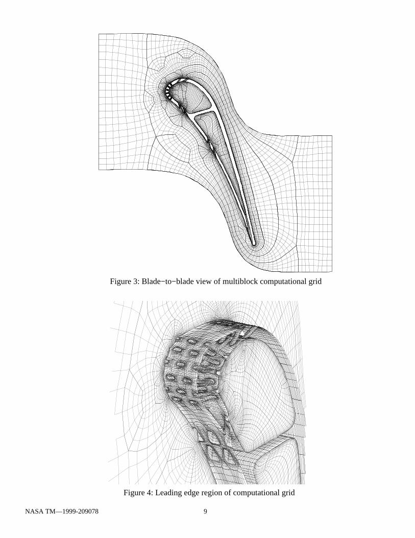
Figure 3: Blade−to−blade view of multiblock computational grid
Figure 4: Leading edge region of computational grid
NASA TM—1999-209078 9
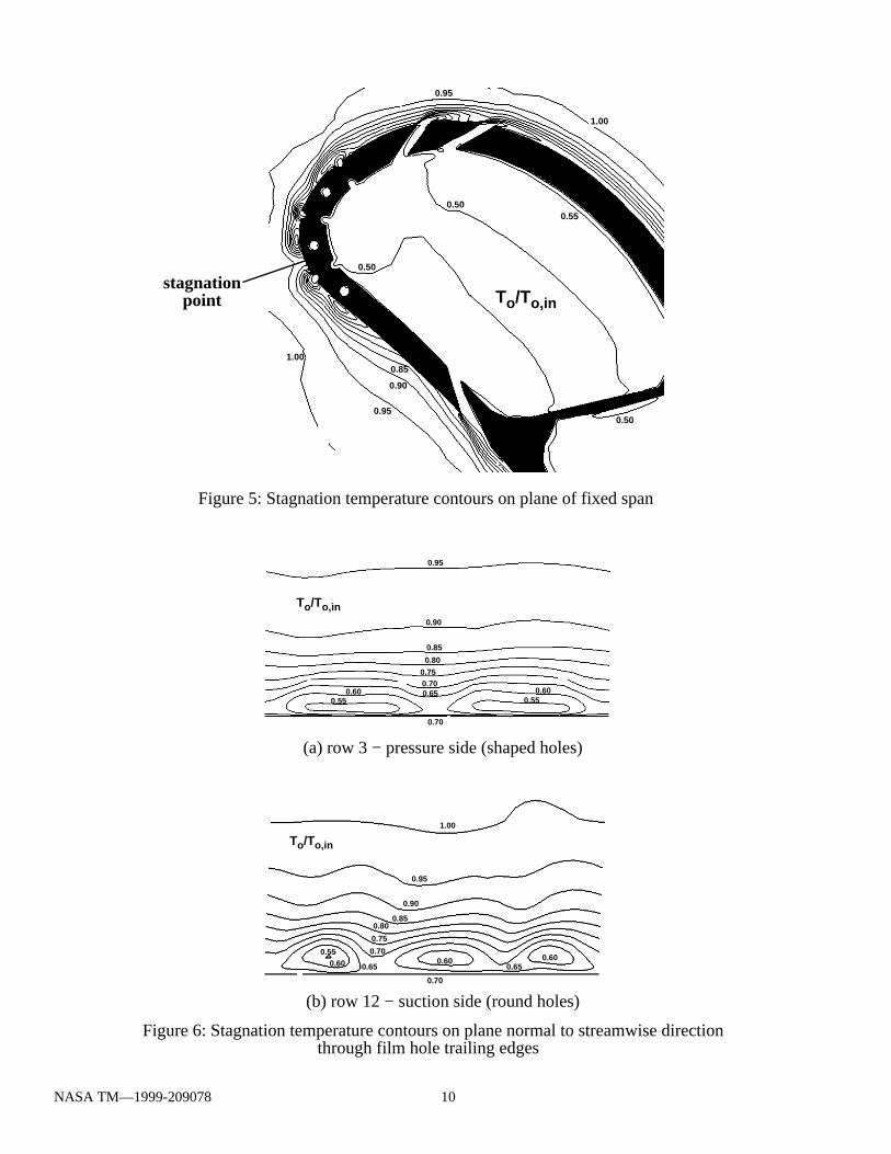
Figure 6: Stagnation temperature contours on plane normal to streamwise direction through film hole trailing edges
(a) row 3 − pressure side (shaped holes)
(b) row 12 − suction side (round holes)
0.95
0.90
0.85
0.80
0.750.700.650.60
0.55 0.55
0.70
0.60
To/To,in
1.00
0.95
0.90
0.850.80
0.75
0.70
0.650.60 0.60
0.70
0.550.60 0.65
To/To,in
0.50
0.50
1.00
1.00
0.95
0.90
0.95
0.50
0.55
0.85
Figure 5: Stagnation temperature contours on plane of fixed span
To/To,instagnation
point
NASA TM—1999-209078 10
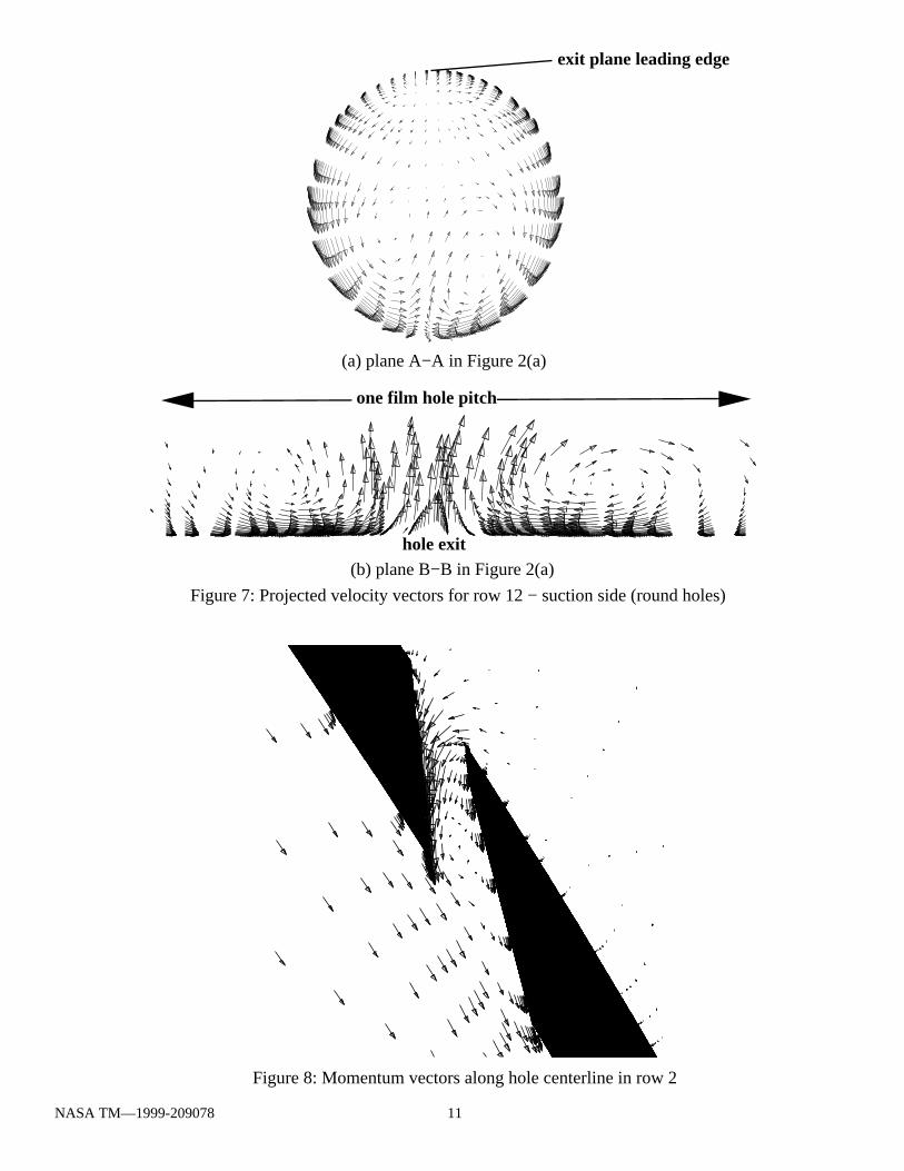
Figure 8: Momentum vectors along hole centerline in row 2
Figure 7: Projected velocity vectors for row 12 − suction side (round holes)
(b) plane B−B in Figure 2(a)
(a) plane A−A in Figure 2(a)
hole exit
exit plane leading edge
one film hole pitch
NASA TM—1999-209078 11
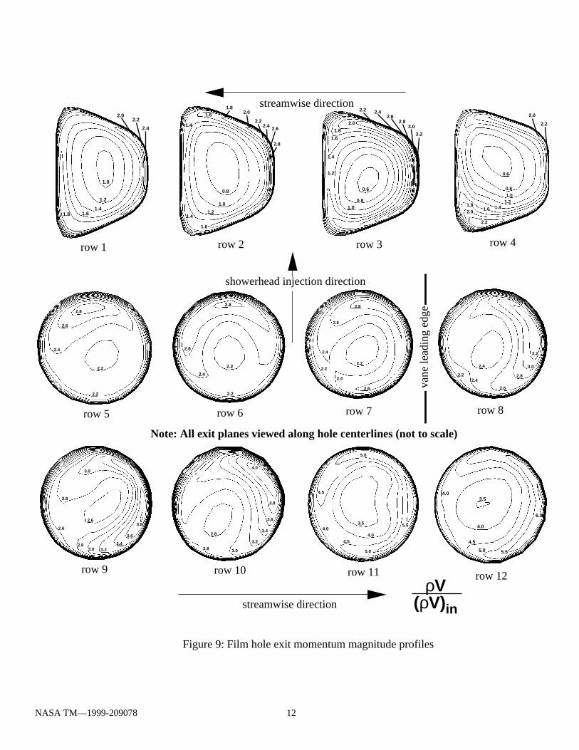
Figure 9: Film hole exit momentum magnitude profiles
row 1 row 2 row 3 row 4
row 5 row 6 row 7 row 8
row 9 row 10 row 11 row 12
streamwise direction
vane
lead
ing
edge
showerhead injection direction
Note: All exit planes viewed along hole centerlines (not to scale)
4.0
3.8
3.6
3.4
3.2
3.0
2.8
2.8
3.8
3.6
3.43.23.0
2.8
2.6
2.6
2.8
3.0
3.2
3.0
2.8
2.6
2.4
2.42.2
2.8
2.6
2.4
2.2
2.2
0.8
1.0
1.21.4
1.4
1.6
1.6
1.82.0
2.22.4 2.6
2.8
streamwise direction
0.6
0.81.0
1.2
1.4
1.6
1.8
2.0
2.2 2.42.6
2.83.0
3.2
2.2
0.6
0.81.0
1.2
1.6 1.42.01.8
2.0
2.2
ρV(ρV)in
1.0
1.2
1.41.61.8
2.02.2
2.4
2.8
2.6
2.6
2.4
2.4
2.22.2
2.8
2.6
2.4
2.2
2.2
5.5
5.0
5.0
4.5
4.54.0
3.54.0
6.0
5.55.0
4.5
4.0
3.54.0
NASA TM—1999-209078 12

Figure 10: Film hole exit stagnation temperature profiles
row 1 row 2 row 3 row 4
row 5 row 6 row 7 row 8
row 9 row 10 row 11 row 12
streamwise direction
streamwise direction
vane
lead
ing
edge
showerhead injection direction
Note: All exit planes viewed along hole centerlines (not to scale)
0.95
0.90
0.90
0.850.80
1.00
0.95
1.00
0.95
1.00
0.950.90
0.85
0.80
0.75
0.70
0.950.90
0.85
0.80
1.00
0.95
0.90
0.85
0.95
0.90
0.90
0.85
0.90
0.85 0.80
0.90
0.85
0.80
0.80
0.80
0.70
0.60
0.50
0.40
0.70
0.60
0.80
0.80
0.800.70
0.70
0.60
0.60
0.80
0.70
0.60
0.50
0.70
0.600.90
0.90
0.80
0.70
Tw − To
Tw − Tc
NASA TM—1999-209078 13
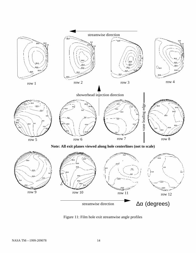
Figure 11: Film hole exit streamwise angle profiles
row 1 row 2 row 3 row 4
row 5 row 6 row 7 row 8
row 9 row 10 row 11 row 12
streamwise direction
vane
lead
ing
edge
showerhead injection direction
Note: All exit planes viewed along hole centerlines (not to scale)
5.0
10.0
10.015.0
20.0
25.0
15.0
5.0
5.010.0
15.0
15.0
10.0
20.0
20.0
25.0
0.0
0.0
−5.0
−5.0
−10.0
−10.0
−15.0
−20.0
5.0 0.0
−5.0
−10.0
10.015.0
20.0
0.0−5.0
5.0
10.0
15.0
10.0 5.0
0.0
0.0
−5.0
−5.0−10.0
−10.0
−15.0−20.0
15.0
20.0
25.0
30.0
25.0
20.0
15.0
15.0
10.0
15.0
5.0
0.0
0.0
−5.0
−5.0
−10.0
−15.0
−10.0
0.0
−5.0
−10.0
−15.0
0.0
5.0
−5.0
25.0
20.0
15.015.0
10.05.0
20.0
30.0
25.0
20.0
15.0
15.0
15.0
10.0
5.0
0.0
streamwise direction
30.0
25.0
20.0
15.0
15.010.0
10.0
5.0
10.05.0
0.0
10.0
15.0
15.0
20.0
20.0
25.0
30.035.0
∆α (degrees)
NASA TM—1999-209078 14
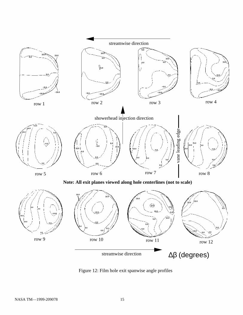
Figure 12: Film hole exit spanwise angle profiles
row 1 row 2 row 3 row 4
row 5 row 6 row 7 row 8
row 9 row 10 row 11 row 12
streamwise direction
streamwise direction
vane
lead
ing
edge
showerhead injection direction
Note: All exit planes viewed along hole centerlines (not to scale)
−10.0
−5.0
0.05.0
10.0
15.0
0.0
−5.0
0.05.0
10.0
15.0
0.0
5.0
−5.0
0.0
0.0
5.0
10.0
5.0
10.0
5.0
0.0
−5.05.0
10.0
0.0
0.0
15.0
10.0
5.0
0.0
−5.0
5.0
15.0
10.0
5.0
0.0
−5.0 −10.0
0.0
5.0
10.0
−5.0
−10.0
5.0
0.0
0.0
5.0
5.0
10.0
−5.0 −10.0
5.0
10.0
0.0−5.0
0.0
15.0
−10.0
15.0
10.0
5.0
0.0
−5.0
10.0
5.0
0.0
10.0
0.0
5.010.0
−5.0
−10.0
15.0
−15.0
−10.0
−5.0
0.05.0
0.05.0
10.010.0
∆β (degrees)
NASA TM—1999-209078 15
–0.004
0.008
0.004
0.000
Figure 13: Overall Stanton number values near vane leading edge
overall Stanton number, St in
0.80
0.10
0.45
Figure 14: Film effectiveness values near vane leading edge
film effectiveness, η
0.005
0.025
0.015
Figure 15: Adiabatic wall Stanton number values near vane leading edge
adiabatic wall Stanton number, St aw
showerhead flow direction
showerhead flow direction
showerhead flow direction
3 45 6 7 8 9 10
11 12
pressure suction
3 45 6 7 8 9 10
11 12
pressure suction
3 45 6 7 8 9 10
11 12
pressure suction
NASA TM—1999-209078 16
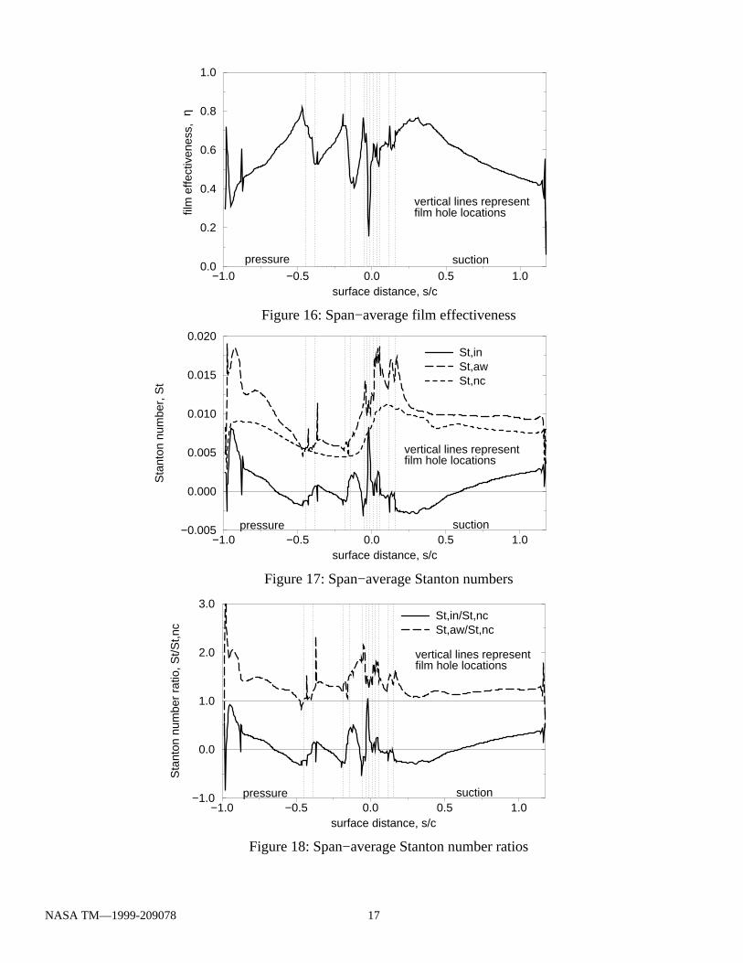
Figure 16: Span−average film effectiveness
Figure 18: Span−average Stanton number ratios
−1.0 −0.5 0.0 0.5 1.0surface distance, s/c
0.0
0.2
0.4
0.6
0.8
1.0
film
effe
ctiv
enes
s,
pressure suction
vertical lines representfilm hole locations
η
Figure 17: Span−average Stanton numbers
−1.0 −0.5 0.0 0.5 1.0surface distance, s/c
−0.005
0.000
0.005
0.010
0.015
0.020
Sta
nton
num
ber,
St
St,inSt,awSt,nc
pressure suction
vertical lines representfilm hole locations
−1.0 −0.5 0.0 0.5 1.0surface distance, s/c
−1.0
0.0
1.0
2.0
3.0
Sta
nton
num
ber
ratio
, St/S
t,nc
St,in/St,ncSt,aw/St,nc
pressure suction
vertical lines representfilm hole locations
NASA TM—1999-209078 17

This publication is available from the NASA Center for AeroSpace Information, (301) 621–0390.
REPORT DOCUMENTATION PAGE
2. REPORT DATE
19. SECURITY CLASSIFICATION OF ABSTRACT
18. SECURITY CLASSIFICATION OF THIS PAGE
Public reporting burden for this collection of information is estimated to average 1 hour per response, including the time for reviewing instructions, searching existing data sources,gathering and maintaining the data needed, and completing and reviewing the collection of information. Send comments regarding this burden estimate or any other aspect of thiscollection of information, including suggestions for reducing this burden, to Washington Headquarters Services, Directorate for Information Operations and Reports, 1215 JeffersonDavis Highway, Suite 1204, Arlington, VA 22202-4302, and to the Office of Management and Budget, Paperwork Reduction Project (0704-0188), Washington, DC 20503.
NSN 7540-01-280-5500 Standard Form 298 (Rev. 2-89)Prescribed by ANSI Std. Z39-18298-102
Form Approved
OMB No. 0704-0188
12b. DISTRIBUTION CODE
8. PERFORMING ORGANIZATION REPORT NUMBER
5. FUNDING NUMBERS
3. REPORT TYPE AND DATES COVERED
4. TITLE AND SUBTITLE
6. AUTHOR(S)
7. PERFORMING ORGANIZATION NAME(S) AND ADDRESS(ES)
11. SUPPLEMENTARY NOTES
12a. DISTRIBUTION/AVAILABILITY STATEMENT
13. ABSTRACT (Maximum 200 words)
14. SUBJECT TERMS
17. SECURITY CLASSIFICATION OF REPORT
16. PRICE CODE
15. NUMBER OF PAGES
20. LIMITATION OF ABSTRACT
Unclassified Unclassified
Technical Memorandum
Unclassified
National Aeronautics and Space AdministrationJohn H. Glenn Research Center at Lewis FieldCleveland, Ohio 44135–3191
1. AGENCY USE ONLY (Leave blank)
10. SPONSORING/MONITORING AGENCY REPORT NUMBER
9. SPONSORING/MONITORING AGENCY NAME(S) AND ADDRESS(ES)
National Aeronautics and Space AdministrationWashington, DC 20546–0001
April 1999
NASA TM—1999-209078
E–11638
WU–523–26–13–00
23
A03
A Three-Dimensional Coupled Internal/External Simulation of a Film-CooledTurbine Vane
James D. Heidmann, David L. Rigby, and Ali A. Ameri
Turbines; Heat transfer; Film cooling
Unclassified -UnlimitedSubject Categories: 34, 07, and 02 Distribution: Nonstandard
Prepared for the 44th Gas Turbine and Aeroengine Congress, Exposition, and Users' Symposium sponsored by the International GasTurbine Institute of the American Society of Mechanical Engineers, Indianapolis, Indiana, June 7–10, 1999. James D. Heidmann, NASAGlenn Research Center; David L. Rigby, Dynacs Engineering Co., Inc., 2001 Aerospace Parkway, Brook Park, Ohio 44142 (work fundedby NASA Contract NAS3–98008); and Ali A. Ameri, AYT Corporation, 2001 Aerospace Parkway, Brook Park, Ohio 44142 (workfunded by NASA Contract NAS3–27571). Responsible person, James D. Heidmann, organization code 5820, (216) 433–3604.
A three-dimensional Navier-Stoker simulation has been performed for a realistic film-cooled turbine vane using the LeRC-HT code. The simulation includes the flow regions inside the coolant plena and film cooling holes in addition to theexternal flow. The vane is the subject of an upcoming NASA Glenn Research Center experiment and has both circularcross-section and shaped film cooling holes. This complex geometry is modeled using a multi-block grid which accuratelydiscretizes the actual vane geometry including shaped holes. The simulation matches operating conditions for the plannedexperiment and assumes periodicity in the spanwise direction on the scale of one pitch of the film cooling hole pattern.Two computations were performed for different isothermal wall temperatures, allowing independent determination of heattransfer coefficients and film effectiveness values. The results indicate separate localized regions of high heat transfercoefficient values, while the shaped holes provide a reduction in heat flux through both parameters. Hole exit data indicaterather simple skewed profiles for the round holes, but complex profiles for the shaped holes with mass fluxes skewedstrongly toward their leading edges.